


![Additive Manufacturing Technologies: 3D printing in Organic … · 1986, [13] the most common being Fused Deposition Modeling (FDM), StereoLithogrAphy (SLA), Selective Laser Sintering](https://static.fdocuments.net/doc/165x107/5f604f5ede94763e98239c03/additive-manufacturing-technologies-3d-printing-in-organic-1986-13-the-most.jpg)
Languages
Pages
Legal


20
Rapid Manufacturing, Rapid Tooling, additive manufacturing technologies, elastic models
Radosław WICHNIAREK*, Filip GÓRSKI**, Wiesław KUCZKO***
APPLICATION OF ADDITIVE TECHNOLOGY
OF FUSED DEPOSITION MODELING
FOR MANUFACTURING SMALL SERIES
OF ELASTIC MODELS
Abstract
The paper presents an application of additive method of Fused Depo-sition Modeling for manufacturing of small series of elastic models. Additive FDM technology is used to produce a casting mould for multiple use. Process of manufacturing of small series of products consists in casting a two-component silicone rubber degassed using vacuum chamber into a multiple use mould. The paper shows the course of the process and related problems on the example of industrial product – a cylindrical seal. The casting mould was produced out of ABS material using BST 1200 machine, whereas casted elastic models were made out of XTX 45 silicone rubber.
1. INTRODUCTION
1.1 . Basic information
Additive Manufacturing Technologies (AMTs, also known as 3D printing
techniques) allow to manufacture physical, three-dimensional models, prototypes
and also some products or parts directly from their digital representation [8].
There are three main groups of applications of these technologies – Rapid Prototy-
ping, Rapid Manufacturing and Rapid Tooling [2,10].
* Poznań University of Technology, Chair of Management and Production Engineering,
Piotrowo 3 Str, PL-60-965 Poznan, [email protected] **
Poznan University of Technology, Chair of Management and Production Engineering,
Piotrowo 3 Str, PL-60-965 Poznan, [email protected] ***
Poznan University of Technology, Chair of Management and Production Engineering,
Piotrowo 3 Str, PL-60-965 Poznan, [email protected]

21
Rapid manufacturing of small series of finished products is often based upon
the Vacuum Casting technology – a process complementary to additive
technologies [9]. This technology allows to effectively create copies of elements
manufactured by additive technologies, using chemically hardened resins as
a build material, usually for thorough testing and evaluation of prototyped
elements [3]. Molds for this method are manufactured using two component
silicone rubbers vulcanizing in the room temperature and the casting material –
two component resin – is usually composed in a way to mimic properties
of various plastics. Both mold manufacturing and subsequent casting (the mold
can be used many times depending on the geometry and conditions, but never
more than for approx. 100 castings) requires degassing of the liquid material
using a vacuum chamber [7].
The Vacuum Casting method is efficient and popular, but it has certain
limitations – there is no possibility of manufacturing elements with elastic
properties [12]. This paper presents a new process (designed and tested
by the authors) of manufacturing short series of elastic products. The process
is based on principles of the VC method, using the silicone rubber (similar in
properties to some widely used elastomers) as a build material. A casting mold
for this process is manufactured using one of the additive technologies – namely
Fused Deposition Modeling.
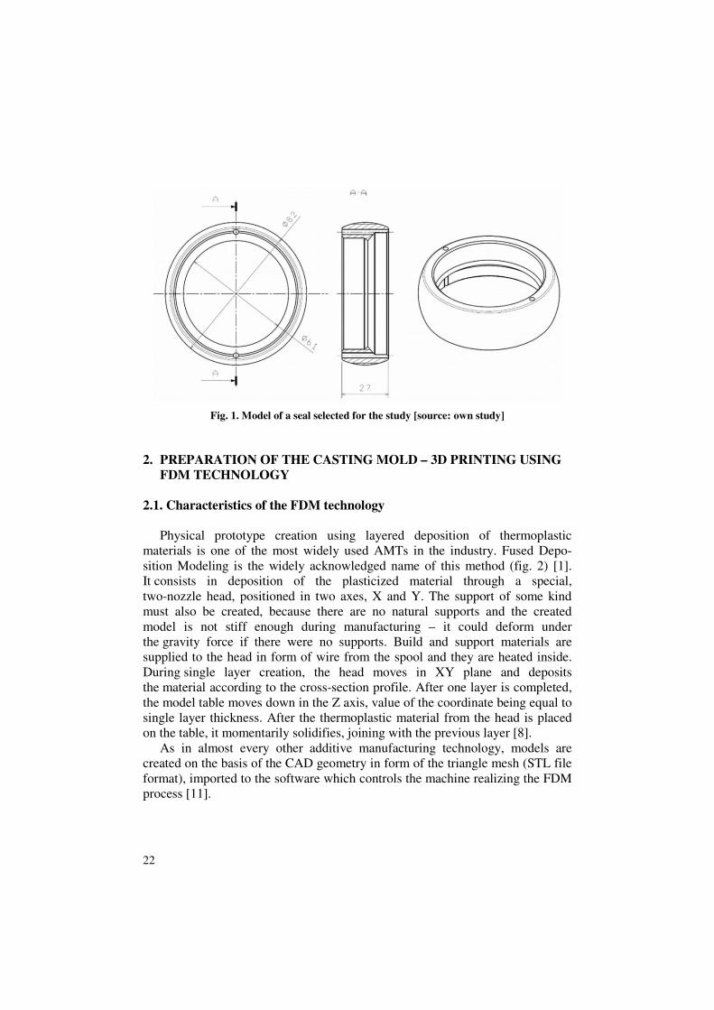
1.2. Place and subject of the practical studies
Research of the process of manufacturing short series of elastic products
using FDM method was conducted in the Laboratory of Rapid Manufacturing,
localized in the Chair of Production Engineering and Management of Faculty
of Mechanical Engineering at Poznań University of Technology. As a base
model for process development and tests, a seal of cylindrical shape was selected
(Figure 1).
Process of manufacturing of short series of products out of elastic material
using the described process consists of the following stages:
- design and manufacturing of the reusable casting mold out of the ABS
material, using additive technology – Fused Deposition Modeling,
- casting in the manufactured mold using additive silicone vulcanizing
in the room temperature as a build material,
- finishing and evaluation of the obtained castings.
As the additive FDM technology is in this case used to manufacture tooling
for the casting process, this application of AMTs should be considered as
the Rapid Tooling.
22
Fig. 1. Model of a seal selected for the study [source: own study]
2. PREPARATION OF THE CASTING MOLD – 3D PRINTING USING
FDM TECHNOLOGY
2.1. Characteristics of the FDM technology
Physical prototype creation using layered deposition of thermoplastic
materials is one of the most widely used AMTs in the industry. Fused Depo-
sition Modeling is the widely acknowledged name of this method (fig. 2) [1].
It consists in deposition of the plasticized material through a special,
two-nozzle head, positioned in two axes, X and Y. The support of some kind
must also be created, because there are no natural supports and the created
model is not stiff enough during manufacturing – it could deform under
the gravity force if there were no supports. Build and support materials are
supplied to the head in form of wire from the spool and they are heated inside.
During single layer creation, the head moves in XY plane and deposits
the material according to the cross-section profile. After one layer is completed,
the model table moves down in the Z axis, value of the coordinate being equal to
single layer thickness. After the thermoplastic material from the head is placed
on the table, it momentarily solidifies, joining with the previous layer [8].
As in almost every other additive manufacturing technology, models are
created on the basis of the CAD geometry in form of the triangle mesh (STL file
format), imported to the software which controls the machine realizing the FDM
process [11].

23
Fig. 2. Scheme of the FDM method [source: own study]
As a build material, usually the ABS material is used (ABS stands
for acrylonitrile butadiene styrene), other thermoplastics can be used too.
Support material type depends on method of the support removal (mechanically –
by force or chemically – by dissolving the support in the liquid solution).
The Laboratory of the Rapid Manufacturing is equipped with the Dimension
BST 1200 machine, manufactured by the company Stratasys. ABS material is
used for both model and support, the support is removed mechanically.
The machine allows to build models with maximum base size of 254 mm x
254 mm and maximum height of 305 mm. Models of larger size can be built
by joining the smaller models, e.g. by gluing them together.
Models manufactured using the FDM method are ready for use immediately
after the support is removed. They have good mechanical properties, but their
visual quality is mostly poor due to so-called staircase effect (which occurs in each
layered manufacturing technology) [4]. To obtain models with high visual quality,
post-processing is required – processes like sanding, grinding, drilling or painting
can be applied to the FDM model to improve its quality and functionality.

24
Prototypes manufactured using FDM technology are used mostly as visual
and functional prototypes. Apart from the prototyping, the ABS models
manufactured additively can be also used as patterns for the Vacuum Casting
process [6]. The process of elastic model manufacturing presented in the next part
of this paper can be treated as an inversion of the classic Vacuum Casting method
– ABS model is used as a mold, while the silicone is used as a build material.
2.2. Manufacturing of the casting mold using the FDM process
Casting mold for manufacturing of the seal models was created directly from
the CAD model. The first stage of preparation of the mold was therefore
a creation of such model. It was made in the CATIA v5 CAD system, basing on
the CAD model of the manufactured element – the seal. Shape of the mold cavity
was created using Boolean operations (subtraction of solids representing the outer
frame of the mold and shape of the model – fig. 3). Additionally, holes were
added for fixing elements and a simple gating system was designed (consisting
of pouring cup and gas vents). The whole mold was divided into two halves.
Fig. 3. CAD model of one half of the casting mould [source: own study]
On the basis of the solid model of two halves of the mold, triangle meshes
were created and saved to STL files. These files were then imported to
the control software of the BST 1200 machine. Then, NC programs containing
information about paths of the head in subsequent layers were automatically
generated and sent to the machine. After manufacturing of both mold halves,
the post processing was performed. It consisted in removal of the support
material, insertion of some fixing elements (namely, steel pins) and drilling

25
of small gas vents (it is not possible to plan these holes in the CAD model,
as their diameter is very small – the same as the width of the single thread
of material, so they would not be manufactured during the additive process).
Finished mold parts are shown in the fig. 4.
Fig. 4. Halves of the casting mold produced using
FDM technology [source: own study]
3. CASTING OF THE ELASTIC MODELS
3.1. Material characterization of the XTX 45 silicone
XTX 45 silicone belongs to a group of silicone rubbers vulcanizing
in the room temperature (no necessity of heating). It is a two component material
– the basis is a liquid material of very high viscosity. To obtain a solid
elastomer, the base needs to be mixed with the catalyst in 10:1 proportion.
Working time of the mixture in room temperature is 90 minutes since the mixing
is complete (in higher ambient temperatures this time is shortened and in lower –
lengthened) and hardening time is about 15 hours (it is also dependent on
the ambient temperature). Properties of the silicone are presented in the table 1.
After hardening, a material from the elastomer group is obtained. Mechanical
properties of the XTX 45 silicone in the solid form (after hardening) are good
enough to use it for the planned task.

26
Tab. 1. Properties of XTX 45 silicone used during the study
Property name Value
Mixture proportion 10 : 1
Part A color (base) Translucent
Part B color (catalyst) Translucent
Part A viscosity 70000 cPs
Part B viscosity 90 cPs
Mixture viscosity 35000 cPs
Density 1,12 kg / dm3
Working time at 23°C 90 min.
Hardening time at 23°C 15 h
Shore A hardness after 24 h 43 ± 2 Shore A
Tensile strength 6,5 ± 0,5 N/mm2
Elongation at break 400 ± 20%
Shear resistance > 20 N/mm
3.2. Course of the casting process
The actual process of casting of elastic models using XTX 45 silicone
consists of several basic stages.
The first stage is preparation of the mold for casting (fig. 5). The following
actions need to be performed:
- cleaning of the mold cavity,
- insertion of the fixing elements (pins),
- tight connection of two mold halves in a temporary way (to ensure
the possibility of getting the model out of the mold without damaging it),
- insertion of the external gating system elements,
- placement of the mold in a way to ensure difference of height levels
of gating system entry point and exit (entry point should be placed on
a lower level than the exit point).
The second stage of the process is material preparation. Applied silicone
consists of two components – the base and the catalyst. Preparation of the mate-
rial requires performing of the following actions:
- calculation of material quantity necessary for the task,
- weighing the proper amounts of the base and the catalyst,
- mixing the base with the catalyst and optionally with some dyes,
if a certain color of the finished element is required,
- degassing of the silicone by placing it in the vacuum for about one minute.

27
Fig. 5. ABS casting mould ready for casting [source: own study]
The last stage was performed using the MCP 4/01 HEK vacuum chamber
(fig. 6). It is noteworthy that it is not entirely necessary to degas the silicone
(especially when manufacturing very small elements), but models manufactured
without degassing are characterized with presence of the air bubbles in large
portion of the casting volume, which decreases the level of product mechanical
properties in a significant way. During degassing the silicone should be placed in
a vessel of volume at least twice as large as the base volume of the raw, liquid
material – air bubbles running out of the material cause a significant, yet
temporary increase in volume of the material.
Fig. 6. Vacuum chamber MCP 4/01 used for silicone degassing [source: own study]

28
The next stage is pouring the material into the mold. Filling the previously
prepared casting mold with degassed silicone can be carried out gravitationally
(in case of larger molds), but for more rapid and accurate filling of the mold
cavity, pressure casting was used. The pressure was exerted by manual pressing
of the material feeder (fig. 7). Value of the pressure and character of its
variations during the mold cavity filling have no observable effects on quality
and properties of obtained models.
The mold is entirely filled when the liquid material appears in the exit point
of the gating system, assuming that there is a visible height difference between
the pouring cup and the exit point.
Fig. 7. Pouring the silicone into the mould [source: own study]
After the silicone is hardened (solidification is usually complete after 12-15
hours), the mold can be opened and the model can be taken out (fig. 8).
During mold disassembly it is important to remember that the silicone precisely
fills the mold cavity, including all sub-cavities, even of a very small size. In case
of the mold created using FDM technology, where the staircase effect is very
distinct and mold surface is not smooth, the silicone model will require
considerably high strength to divide it from the mold surface. It is therefore
important to perform this process carefully, especially when using metal tools,
to leave both the model and the mold intact (with no damage).

29
Fig. 8. Hardened model ready to be taken out of the mould [source: own study]
Directly after removal of the elastic model from the mold, it should be evaluated,
especially concerning occurrence of the casting defects. The most frequently
occurring defect in this type of models is presence of air bubbles and pockets
(similar as shrink cavities in metal castings), appearing as a result of insufficient
degassing of the raw material (fig. 9). Air pockets – if they are present – are usually
located deep inside the model volume (as opposed to these appearing in resin
models manufactured using classic approach to Vacuum Casting technology) and
they have no impact on its shape and dimensional accuracy. Still, these flaws usually
disqualify the product, especially when they have considerably large volume, as they
impair the mechanical properties of the product.
Applied additive silicone does not present any visible shrinkage, which
means that there are no possibilities of its compensation, neither on the design
stage, nor during the manufacturing process.
Fig. 9. Flaws occurring in silicone models – air pockets [source: own study]
The model removed from the mold is not a finished product yet – all
the casting technologies make use of some type of post processing (the fini-
shing). In this case it consists mostly in cleaning the model and removing the
rest of the gating system and traces of mold division line. It is usually done using
cutting tools or machining (fig. 10).

30
Fig. 10. Model taken out of the mould (on the left) and after post processing
(on the right) [source: own study]
4. CONCLUSIONS, SUMMARY
Basing on the course and results of the casting of short series of elastic
products in ABS molds, the following conclusions can be drawn:
- Applied silicone precisely fills the mold cavity, accurately representing all
the surfaces (despite low castability in liquid form), so in case of surfaces
that are irregular, uneven or with pockets, holes etc., there are problems
with disassembling two mold halves and removing the product.
These problems can be avoided by applying appropriate finishing
treatment of the mold cavity (e.g. grinding).
- Silicone adheres to the mold surface strongly, so apart from appro-
priate surface finishing, the mold cavity should also be covered with
a dedicated separator. It is well advised especially for models with more
complex shapes.
- During the casting process, the ABS mold is subjected to mechanical wear
(especially as a result of applying certain forces during model removal),
so number of models obtained from one mold is limited – it would be
advisable to further study the influence of the model geometry complexity
and casting process course on the level of the mechanical wear
of the mold, to be able to estimate the maximum number of pieces
obtained from the given mold.
- Unlike during the regular Vacuum Casting process, the mold is not
translucent, so it is not possible to determine the locations of air pockets
before the model is removed from the mold – this is a clear disadvantage
of using the FDM-produced molds.
- Thanks to using model material of elastic properties, the mold does not need
to have any drafts or other special features to facilitate the model removal.

31
- Silicone does not present any visible shrinkage, so there is no need
to compensate it.
- Defects in form of air bubbles and pockets can be easily avoided
by thorough degassing of the base material.
To sum up, it can be stated that manufacturing products out of elastic
materials using casting process in ABS molds prepared using additive FDM
technology is quite possible, as long as proper process conditions are
maintained. Appearing problems (defects, troubles with mold disassembly) can
be solved by taking appropriate actions – modification of the mold, more
thorough degassing or application of separators. It can also be said that amount
of work needed to achieve satisfying results for this method is not high.
A disadvantage of this process which may increase the cost of its possible
implementation is necessity of applying the vacuum chamber to degas the base
material. Still, described process remains one of the fastest and cheapest ways
of producing short series of fully functional elastic products.
REFERENCES
[1] BELLINI A., GUCERI S.: Mechanical characterization of parts fabricated using fused deposition modeling. Rapid Prototyping Journal, vol. 9, 2003.
[2] HULL C., et al.: Rapid prototyping: current technology and future potential. Rapid Prototyping
Journal, vol. 1 no. 1, pp. 11-19, 1995.
[3] KAI C. C., HOWE C. T., HOE E. K.: Integrating Rapid Prototyping and Tooling with Vacuum Casting for Connectors. International Journal of Advanced Manufacturing
Technology. Springer, vol. 14, 617-623, 1998.
[4] KONIECZNY R.: Projektowanie z wykorzystaniem narzędzi Rapid Prototyping,
Mechanik, t.76, nr 12, 2003.
[5] KUCZKO E., et al.: Choosing optimal rapid manufacturing process for thin-walled products using expert algorithm. Journal of Industrial Engineering and Management, vol. 3, no. 2, 2010.
[6] LEE C.W., et al.: Rapid investment casting: direct and indirect approaches via fused deposition modeling. International Journal of Advanced Manufacturing Technology.
Springer, vol. 23, 2003, pp. 93-101.
[7] MAIS G., DUCHSCHERER F.: Vacuum casting - development stage of a special-purpose method. Kunststoffe, German plastics, vol. 81, 1999, pp. 14-16.
[8] PAJĄK E., et al.: Techniki przyrostowe i wirtualna rzeczywistość w procesach przygotowania produkcji. Agencja Reklamowo-Promocyjna „Promocja 21”, Poznań 2011.
[9] PHAM D. T., DIMOV S., LACAN F.: Selective laser sintering: applications and technological capabilities. Proc Instn Mech Engrs, vol. 213 Part B, 1999, pp. 435.
[10] ROSOCHOWSKI A., MATUSZAK A.: Rapid tooling: the state of the art. Journal
of Materials Processing Technology, 106 (1-3), pp. 191-198, 2000.
[11] WEISS E., et al.: Accuracy of parts manufactured by rapid prototyping technology.
7th International Conference of DAAAM Baltic Industrial Engineering, Tallinn, Estonia, 2010.
[12] WEISS E., WARACZYŃSKI B.: Zastosowanie Technologii Vacuum Casting do wytwarzania prototypów funkcjonalnych. Zeszyty Naukowe Politechniki Poznańskiej, no. 5, 2007.
Top Related