


Languages
Pages
Legal


© Alcatel 1
All rights reserved © 2006, AlcatelAlcatel 9110-E Micro-BTS Description
Alcatel 9110-E Micro-BTS DescriptionTRAINING MANUAL
3FL 11947 ABAA–AUB ed 3October 2006
Copyright © 2005 by Alcatel - All rights reservedPassing on and copying of this document, use and communication of its contents
not permitted without written authorization from Alcatel

© Alcatel 2
Safety WarningBoth lethal and dangerous voltages are present within the equipment. Do not wear conductive jewelrywhile working on the equipment. Always observe all safety precautions and do not work on the equipment alone.CautionThe equipment used during this course is electrostatic sensitive. Please observe correct anti-static precautions.Trade MarksAlcatel and MainStreet are trademarks of Alcatel.All other trademarks, service marks and logos (“Marks”) are the property of their respective holders including Alcatel. Users are not permitted to use these Marks without the prior consent of Alcatel or such third party owning the Mark. The absence of a Mark identifier is not a representation that a particular product or service name is not a Mark.CopyrightThis document contains information that is proprietary to Alcatel and may be used for training purposes only. No other use or transmission of all or any part of this document is permitted without Alcatel’s written permission, and must include all copyright and other proprietary notices. No other use or transmission of all or any part of its contents may be used, copied, disclosed or conveyed to any party in any manner whatsoever without prior written permission from Alcatel.Use or transmission of all or any part of this document in violation of any applicable Canadian or other legislation is hereby expressly prohibited.User obtains no rights in the information or in any product, process, technology or trademark which it includes or describes, and is expressly prohibited from modifying the information or creating derivative works without the express written consent of Alcatel.Alcatel, The Alcatel logo, MainStreet and Newbridge are registered trademarks of Alcatel. All other trademarks are the property of their respective owners. Alcatel assumes no responsibility for the accuracy of the information presented, which is subject to change without notice. © 2004 Alcatel. All rights reserved.DisclaimerIn no event will Alcatel be liable for any direct, indirect, special, incidental or consequential damages, including lost profits, lost business or lost data, resulting from the use of or reliance upon the information, whether or not Alcatel has been advised of the possibility of such damages.Mention of non-Alcatel products or services is for information purposes only and constitutes neither an endorsement nor a recommendation.Please refer to technical practices supplied by Alcatel for current information concerning Alcatel equipment and its operation.

© Alcatel 3
Alcatel 9110-E Micro-BTS Description
All rights reserved © 2006, AlcatelAlcatel 9110-E Micro-BTS Description
3
Contents
1 Introduction 1.1 Situation of the Alcatel 9110-E µ-BTS 1.2 Functions of the Alcatel 9110-E µ-BTS 1.3 Main characteristics of the Alcatel 9110-E µ-BTS 1.4 Main features of the Alcatel 9110-E µ-BTS
2 Functional architecture2.1 General functional view of A9110-E µ-BTS2.2 Antenna Network2.3 Telecommunication2.4 Operation and maintenance2.5 Transmission2.6 Clock and power supply2.7 Remote Inventory and BSII interface
3 Hardware Architecture3.1 General architecture view of A9110-E µ-BTS3.2 Basic Unit3.3 Connection Box3.4 Options
Contents
1 Introduction 61.1 Situation of the Alcatel 9110-E µ-BTS 81.2 Functions of the Alcatel 9110-E µ-BTS 101.3 Main characteristics of the Alcatel 9110-E µ-BTS 121.4 Main features of the Alcatel 9110-E µ-BTS 16
2 Functional architecture 202.1 General functional view of A9110-E µ-BTS 222.2 Antenna Network 242.3 Telecommunication 282.4 Operation and maintenance 312.5 Transmission 362.6 Clock and power supply 402.7 Remote Inventory and BSII interface 42
3 Hardware Architecture 453.1 General architecture view of A9110-E µ-BTS 473.2 Basic Unit 493.3 Connection Box 513.4 Options 53
4 Configurations 604.1 Site configuration 624.2 Basic configuration 644.3 Single antenna configuration 664.4 Low loss configuration 684.5 Multiband configuration 70
5 Appendix and Glossary 73

© Alcatel 4
Course title: Alcatel 9100 BTS Description
Reference: 3FL 10477 ACAA - AUP Teaching languages: English - French - German - Arabic - Romanian - Chinese - Portuguese
Standard duration Training methods
or
6
Introduction of theoretical knowledge, based on the presentation of hardware.
Total duration (hrs) 6 Sequence:
Maximum number of participants: 12 (Only applicable to c-learning and v-learning)
Audience:
Personnel in charge of operating the Alcatel Base Transceiver Stations.
Objectives: By the end of the course, participants will be able to identify the: - Role and situation of the BTS; - Functional subsets of the BTS; - Hardware modules of the BTS; - Possible hardware configurations. Prerequisites:
- Training module “Introduction to the Alcatel GSM Network - 3FL 10471 ADAA. - Training module “Alcatel Base Station Subsystem Description Web-based Training - 3FL 10473 ACAB” or “Alcatel
Base Station Subsystem Description - 3FL 10473 ACAA”. Course contents:
Introduction Functional Architecture Hardware Architecture Configurations

© Alcatel 5
Objectives
Instructional objectives Yes (or
Globally yes)
No (or globally
no) Comments
1 Identify the role and situation of the A9110-E µ-BTS
2 Identify the functional subsets of the A9110-E µ-BTS
3 Identify the hardware modules of the A9110-E µ-BTS
4 Identify the possible hardware configurations
Contract number :
Course title : Alcatel 9110-E Micro-BTS Description
Client (Company, centre) :
Language : dates from : to :
Number of trainees : Location :
Surname, First name :
Did you meet the following objectives ?Tick the corresponding box
Please, return this sheet to the trainer at the end of the training

© Alcatel 6
Page intentionally left blank
© Alcatel 7
Alcatel 9110-E Micro-BTS Description
All rights reserved © 2006, AlcatelAlcatel 9110-E Micro-BTS Description
7
1 Introduction

© Alcatel 8
Alcatel 9110-E Micro-BTS Description
All rights reserved © 2006, AlcatelAlcatel 9110-E Micro-BTS Description
8
Introduction
Session presentation
Objective : to be able to identify the role and situation of theA9110-E µ-BTS and to give the main characteristics and features of the A9110-E µ-BTS
Program : page number1.1 Situation of the Alcatel 9110-E µ-BTS 91.2 Functions of the Alcatel 9110-E µ-BTS 11 1.3 Main characteristics of the Alcatel 9110-E µ-BTS 131.4 Main features of the Alcatel 9110-E µ-BTS 17
© Alcatel 9
Alcatel 9110-E Micro-BTS Description
All rights reserved © 2006, AlcatelAlcatel 9110-E Micro-BTS Description
9
1 Introduction
1.1 Situation of the Alcatel 9110-E µ-BTS
© Alcatel 10
Alcatel 9110-E Micro-BTS Description
All rights reserved © 2006, AlcatelAlcatel 9110-E Micro-BTS Description
10
1.1 Situation of the Alcatel 9110-E µ-BTS
Situation of the Alcatel A9110-E µ-BTS
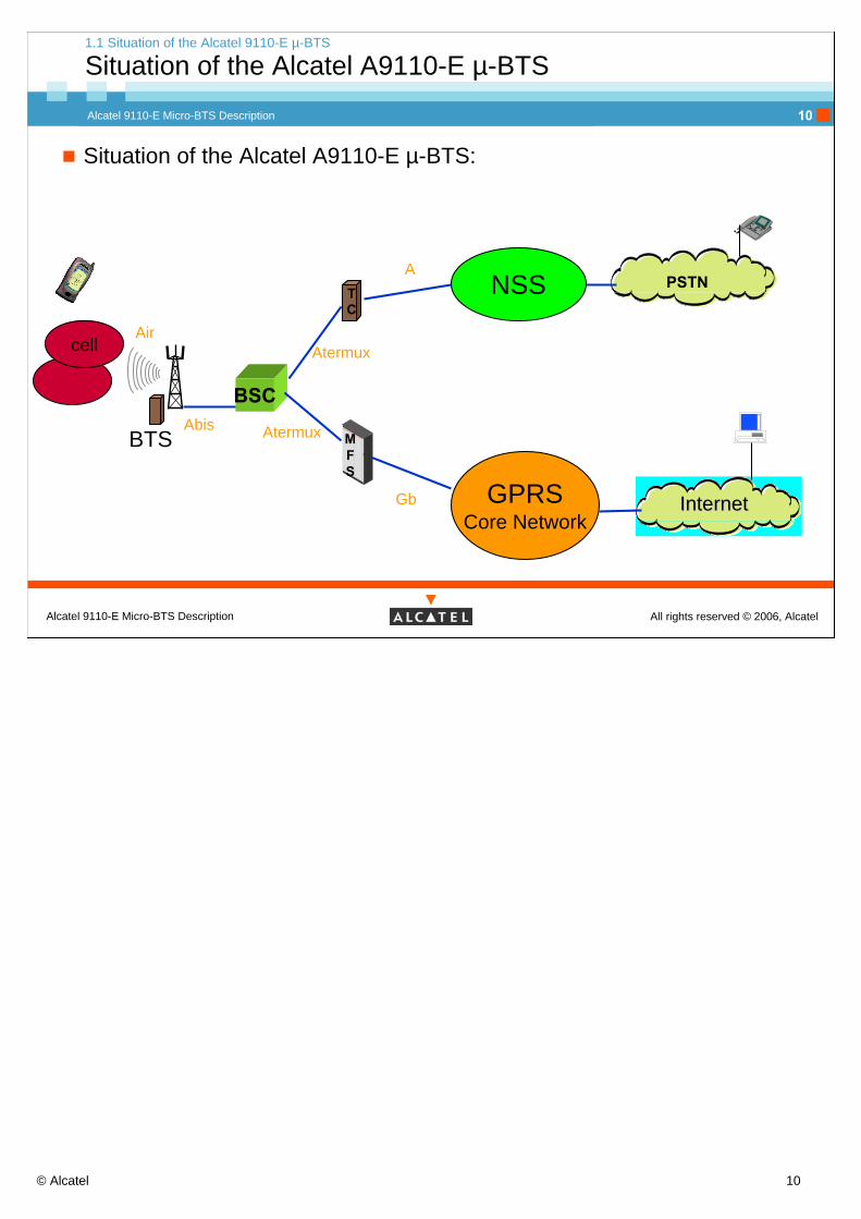
Situation of the Alcatel A9110-E µ-BTS:
TC
BSC
BTS
InternetInternetGb GPRSCore Network
NSS PSTN
MFS
Abis Atermux
A
Aircell Atermux

© Alcatel 11
Alcatel 9110-E Micro-BTS Description
All rights reserved © 2006, AlcatelAlcatel 9110-E Micro-BTS Description
11
1 Introduction
1.2 Functions of the Alcatel 9110-E µ-BTS

© Alcatel 12
Alcatel 9110-E Micro-BTS Description
All rights reserved © 2006, AlcatelAlcatel 9110-E Micro-BTS Description
12
Role of the Alcatel A9110-E µ-BTS:
The Alcatel 9110-E BTS provides two-way radio communication between the PSTN or the Internet world and mobile Stations located in a single GSM cell.
It provides the air interface with the mobile staions (MS) and the Abis interface with the Base Station Controller (BSC).
1.2 Functions of the Alcatel 9110-E µ-BTS
Role of the Alcatel 9110-E µ-BTS
The Alcatel 9110-E BTS can be considered as a radio relays between the subscriber’s mobile station and the network.

© Alcatel 13
Alcatel 9110-E Micro-BTS Description
All rights reserved © 2006, AlcatelAlcatel 9110-E Micro-BTS Description
13
1 Introduction
1.3 Main characteristics of the Alcatel 9110-E µ-BTS

© Alcatel 14
Alcatel 9110-E Micro-BTS Description
All rights reserved © 2006, AlcatelAlcatel 9110-E Micro-BTS Description
14
1.3 Main characteristics of the Alcatel 9110-E µ-BTS
Main benefits
Main benefits of the Alcatel 9110-E µ-BTS
Adaptability :Wall/pool and indoor/outdoor installationDifferent TX power versionsintegrated or remote antennas, ...
Flexibility:One-module concept (“Plug&Play”)Online extension of modules (up to 12 TRE), ...
Evolium BTS Architecture :BTS auto identificationRF cabling detectionRemote inventory,...
BTS auto identification:Auto identification is the capability of the BTS to recognise by it self:
For each managed module, both RIT type and RIT location,The sector to which each ANC belongs to,The mapping TRE/ANCAll the BTS HW and SW capabilities.
RF cabling detectionThis feature allows the BTS to know how the modules in the BTS are interconnected.
The RF cabling detection applies only to the RX cabling.The principle consists in sending, at OMU order, a low voltage DC signal to an ANx reception line, by means of the BCB (internal bus). The TRE(s) receiving this signal will then inform the OMU, specifying if the signal has been received on RXO or RX1. This detection needs to be performed at least at BTS start-up.
The TX cabling is considered correct if the corresponding normal RX cabling is correct. This assumption is based on the usage of either bound cables (1 TX + 2 RX) and bound connectors.
Remote inventory:Most of the information, mainly capabilities and module type versions are retrieved by the Remote Inventory function.Each RIT (replaceable item) stores inventory information (serial number, manufacturing and repair history, hardware capability...) in a flash EEPROM.These information are accessible from BTS terminal or from the OMC-R.
© Alcatel 15
Alcatel 9110-E Micro-BTS Description
All rights reserved © 2006, AlcatelAlcatel 9110-E Micro-BTS Description
15
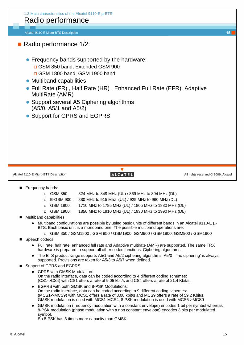
Radio performance 1/2:
Frequency bands supported by the hardware:GSM 850 band, Extended GSM 900GSM 1800 band, GSM 1900 band
Multiband capabilities Full Rate (FR) , Half Rate (HR) , Enhanced Full Rate (EFR), Adaptive MultiRate (AMR)Support several A5 Ciphering algorithms(A5/0, A5/1 and A5/2)Support for GPRS and EGPRS
1.3 Main characteristics of the Alcatel 9110-E µ-BTS
Radio performance
Frequency bands:GSM 850: 824 MHz to 849 MHz (UL) / 869 MHz to 894 MHz (DL)E-GSM 900 : 880 MHz to 915 Mhz (UL) / 925 MHz to 960 MHz (DL)GSM 1800: 1710 MHz to 1785 MHz (UL) / 1805 MHz to 1880 MHz (DL)GSM 1900: 1850 MHz to 1910 MHz (UL) / 1930 MHz to 1990 MHz (DL)
Multiband capabilitiesMultiband configurations are possible by using basic units of different bands in an Alcatel 9110-E µ-BTS. Each basic unit is a monoband one. The possible multiband operations are:
GSM 850 / GSM1800 , GSM 850 / GSM1900, GSM900 / GSM1800, GSM900 / GSM1900Speech codecs
Full rate, half rate, enhanced full rate and Adaptive multirate (AMR) are supported. The same TRX hardware is prepared to support all other codec functions. Ciphering algorithmsThe BTS product range supports A5/1 and A5/2 ciphering algorithms; A5/0 = ‘no ciphering’ is always supported. Provisions are taken for A5/3 to A5/7 when defined.
Support of GPRS and EGPRS.GPRS with GMSK Modulation: On the radio interface, data can be coded according to 4 different coding schemes: (CS1->CS4) with CS1 offers a rate of 9.05 kbit/s and CS4 offers a rate of 21.4 Kbit/s.EGPRS with both GMSK and 8-PSK Modulations: On the radio interface, data can be coded according to 9 different coding schemes:(MCS1->MCS9) with MCS1 offers a rate of 8.08 kbit/s and MCS9 offers a rate of 59.2 Kbit/s.GMSK modulation is used with MCS1-MCS4, 8-PSK modulation is used with MCS5->MCS9GMSK modulation (frequency modulation with a constant envelope) encodes 1 bit per symbol whereas 8-PSK modulation (phase modulation with a non constant envelope) encodes 3 bits per modulated symbol.So 8-PSK has 3 times more capacity than GMSK.

© Alcatel 16
Alcatel 9110-E Micro-BTS Description
All rights reserved © 2006, AlcatelAlcatel 9110-E Micro-BTS Description
16
Radio performance 2/2:
Radio frequency performance:Reference sensitivity higher than GSM requirement (-104 dBm)TX output power:
3 W < GMSK<7 W (single antenna)2 W < 8-PSK < 5 W (2 antennas)
Radio frequency hoppingAntenna diversityLow loss configuration:
1 sector with 2 TREs, with antenna diversity2 sectors with 1 TRE in each sector, without antenna diversity
1.3 Main characteristics of the Alcatel 9110-E µ-BTS
Radio performance
RF performances:The TX output power depends on the frequency band, the modulation used and the type of antenna network (1 or 2 antennas)Radio (synthesized) frequency hopping:The goal is to avoid “gap” in frequency reception for the mobile.The principle is to switch on frequencies predefined in a list during radio transmission.
Two frequency hopping are available:Standard RF hopping mode: A cell with N TRXs can have N-1 TRXs hopping (except the TRX carrying the BCCH), on M frequencies (M usually > N).Pseudo base band RF hopping mode: A cell with N TRXs can have all its N TRXs hopping on N
frequencies.Antenna diversity:The goal is to avoid fading in the frequency reception for the BTS.The same signal with different multi-paths is received in the Base Station where it is processed within 2 independent chains : a Discriminator then identifies the best signal.Low loss configuration:
The goal is to avoid the 3dB loss by passing a combiner.

© Alcatel 17
Alcatel 9110-E Micro-BTS Description
All rights reserved © 2006, AlcatelAlcatel 9110-E Micro-BTS Description
17
1 Introduction
1.4 Main features of the Alcatel 9110-E µ-BTS
© Alcatel 18
Alcatel 9110-E Micro-BTS Description
All rights reserved © 2006, AlcatelAlcatel 9110-E Micro-BTS Description
18
Main features of the Evolium µ-BTS
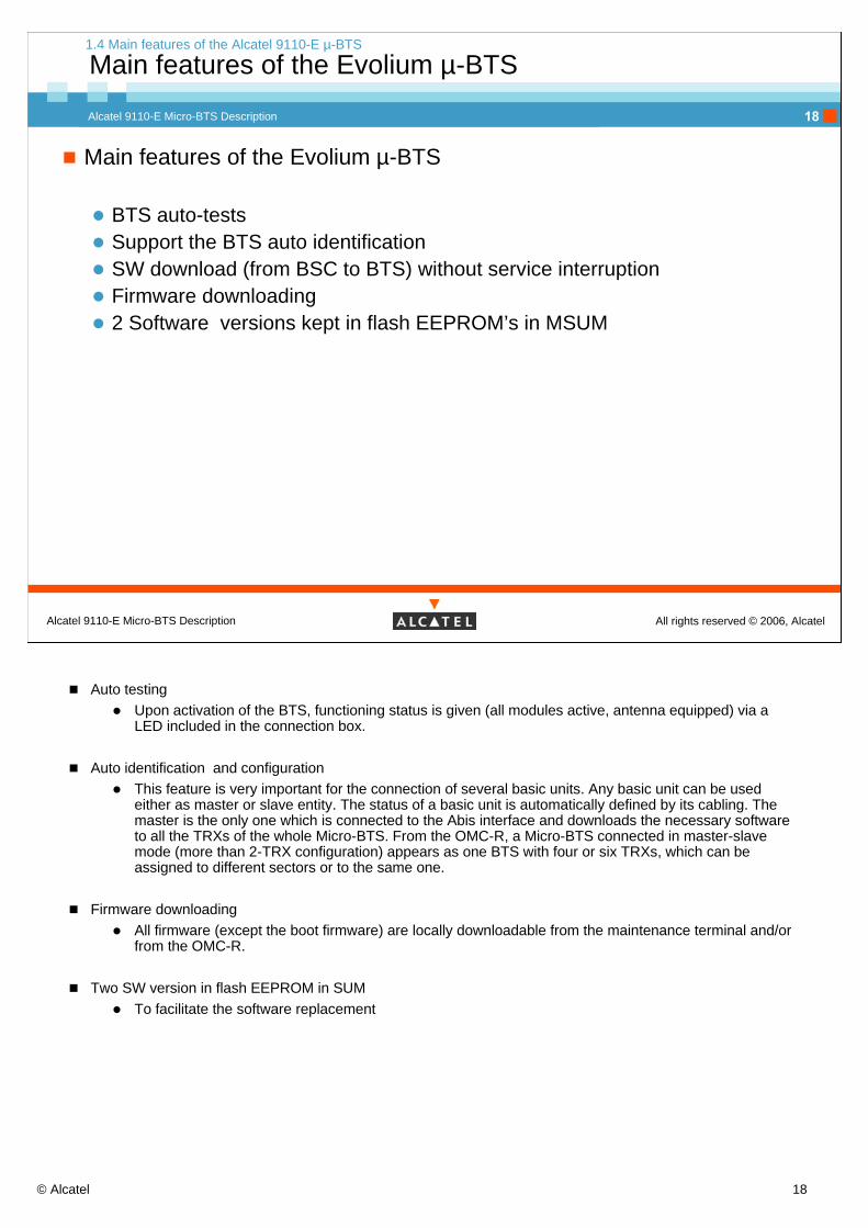
BTS auto-tests Support the BTS auto identificationSW download (from BSC to BTS) without service interruptionFirmware downloading 2 Software versions kept in flash EEPROM’s in MSUM
1.4 Main features of the Alcatel 9110-E µ-BTS
Main features of the Evolium µ-BTS
Auto testingUpon activation of the BTS, functioning status is given (all modules active, antenna equipped) via a LED included in the connection box.
Auto identification and configurationThis feature is very important for the connection of several basic units. Any basic unit can be used either as master or slave entity. The status of a basic unit is automatically defined by its cabling. The master is the only one which is connected to the Abis interface and downloads the necessary software to all the TRXs of the whole Micro-BTS. From the OMC-R, a Micro-BTS connected in master-slave mode (more than 2-TRX configuration) appears as one BTS with four or six TRXs, which can be assigned to different sectors or to the same one.
Firmware downloadingAll firmware (except the boot firmware) are locally downloadable from the maintenance terminal and/or from the OMC-R.
Two SW version in flash EEPROM in SUMTo facilitate the software replacement
© Alcatel 19
Alcatel 9110-E Micro-BTS Description
All rights reserved © 2006, AlcatelAlcatel 9110-E Micro-BTS Description
19
Main features of the Evolium µ-BTS
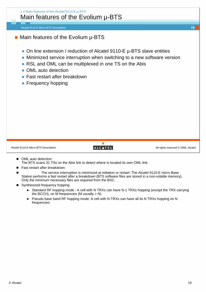
On line extension / reduction of Alcatel 9110-E µ-BTS slave entitiesMinimized service interruption when switching to a new software versionRSL and OML can be multiplexed in one TS on the AbisOML auto detectionFast restart after breakdownFrequency hopping
1.4 Main features of the Alcatel 9110-E µ-BTS
Main features of the Evolium µ-BTS
OML auto detection:The BTS scans 31 TSs on the Abis link to detect where is located its own OML link.Fast restart after breakdown:
The service interruption is minimized at initiation or restart: The Alcatel 9110-E micro Base Station performs a fast restart after a breakdown (BTS software files are stored in a non-volatile memory). Only the minimum necessary files are required from the BSC.Synthesized frequency hopping
Standard RF hopping mode : A cell with N TRXs can have N-1 TRXs hopping (except the TRX carrying the BCCH), on M frequencies (M usually > N).Pseudo base band RF hopping mode: A cell with N TRXs can have all its N TRXs hopping on N frequencies

© Alcatel 20
Alcatel 9110-E Micro-BTS Description
All rights reserved © 2006, AlcatelAlcatel 9110-E Micro-BTS Description
20
1. Introduction
Self-Assessment on the Objectives
Please be reminded to fill in the formSelf-Assessment on the Objectivesfor this moduleThe form can be found in the first partof this course documentation
Objective: to be able to identify the situation and the main characteristics of the Evolium µ-BTS

© Alcatel 21
Alcatel 9110-E Micro-BTS Description
All rights reserved © 2006, AlcatelAlcatel 9110-E Micro-BTS Description
21
2. Functional Architecture

© Alcatel 22
Alcatel 9110-E Micro-BTS Description
All rights reserved © 2006, AlcatelAlcatel 9110-E Micro-BTS Description
22
2. Functional architecture
Session presentation
Objective : to be able to identify the functional subsets of the A9110-E µ-BTS
Program : page number2.1 General functional view of A9110-E µ-BTS 232.2 Antenna Network 252.3 Telecommunication 292.4 Operation and maintenance 322.5 Transmission 372.6 Clock and power supply 412.7 Remote Inventory and BSII interface 43

© Alcatel 23
Alcatel 9110-E Micro-BTS Description
All rights reserved © 2006, AlcatelAlcatel 9110-E Micro-BTS Description
23
2. Functional Architecture
2.1 General functional view of A9110-E µ-BTS
© Alcatel 24
Alcatel 9110-E Micro-BTS Description
All rights reserved © 2006, AlcatelAlcatel 9110-E Micro-BTS Description
24
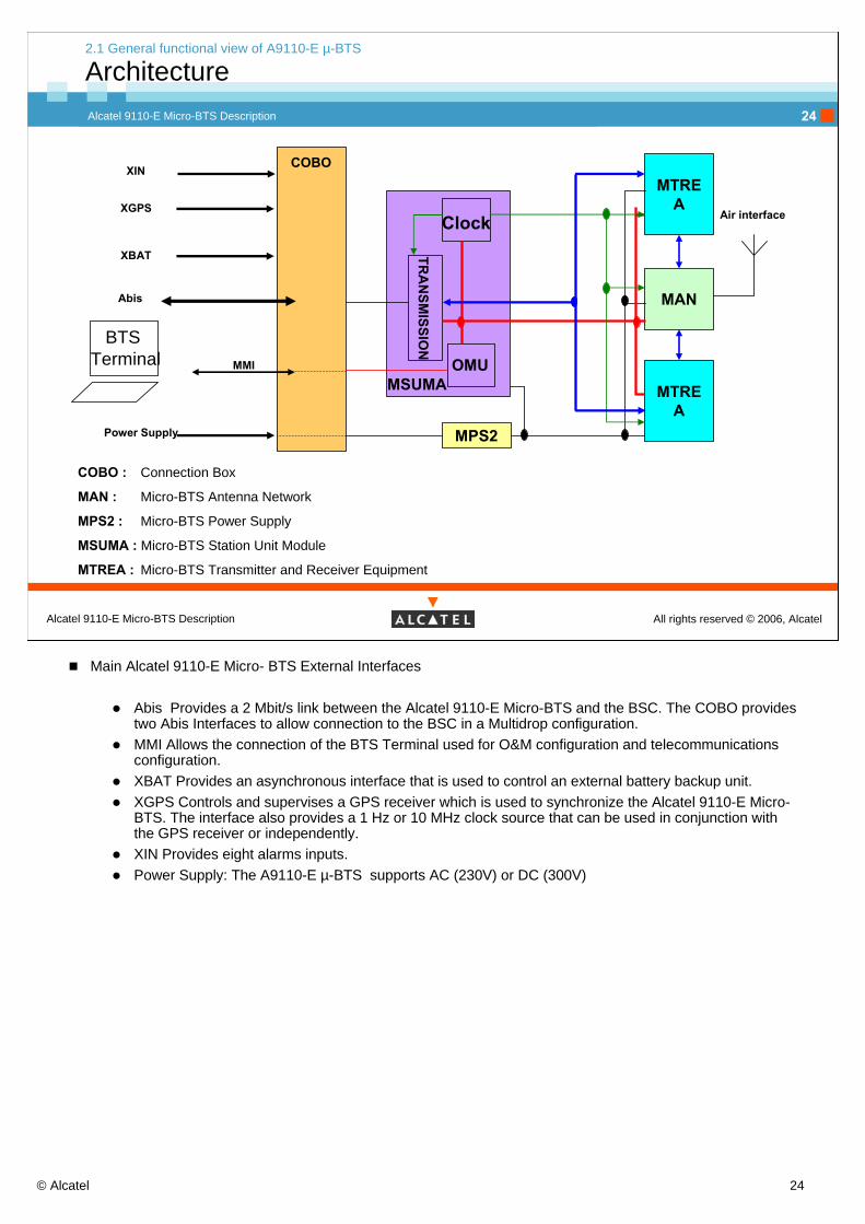
COBO : Connection Box
MAN : Micro-BTS Antenna Network
MPS2 : Micro-BTS Power Supply
MSUMA : Micro-BTS Station Unit Module
MTREA : Micro-BTS Transmitter and Receiver Equipment
MAN
MTREA
MPS2
MTREA
MMI
Abis
Air interface
BTS Terminal
Clock
TRA
NSM
ISSION
OMUMSUMA
Power Supply
XIN COBO
2.1 General functional view of A9110-E µ-BTS
Architecture
XGPS
XBAT
Main Alcatel 9110-E Micro- BTS External Interfaces
Abis Provides a 2 Mbit/s link between the Alcatel 9110-E Micro-BTS and the BSC. The COBO provides two Abis Interfaces to allow connection to the BSC in a Multidrop configuration.MMI Allows the connection of the BTS Terminal used for O&M configuration and telecommunications configuration.XBAT Provides an asynchronous interface that is used to control an external battery backup unit.XGPS Controls and supervises a GPS receiver which is used to synchronize the Alcatel 9110-E Micro-BTS. The interface also provides a 1 Hz or 10 MHz clock source that can be used in conjunction with the GPS receiver or independently.XIN Provides eight alarms inputs.Power Supply: The A9110-E µ-BTS supports AC (230V) or DC (300V)

© Alcatel 25
Alcatel 9110-E Micro-BTS Description
All rights reserved © 2006, AlcatelAlcatel 9110-E Micro-BTS Description
25
2. Functional Architecture
2.2 Antenna Network

© Alcatel 26
Alcatel 9110-E Micro-BTS Description
All rights reserved © 2006, AlcatelAlcatel 9110-E Micro-BTS Description
26
2.2 Antenna network (MAN)
Main functions
The main functions of the MAN are:in Downlink direction:
Isolation of the transmitters from the receiversCombining the output of 2 transmitters to allow them to share a single antennaDuplexing to allow transmitters and receivers to share the same antenna
in Uplink direction:Pre-amplification to amplify the received signals and control the overall gain of the antenna networkSplitting to distribute the received signals to a pair of receivers.

© Alcatel 27
Alcatel 9110-E Micro-BTS Description
All rights reserved © 2006, AlcatelAlcatel 9110-E Micro-BTS Description
27
There are two types of MAN module for the BTS Alcatel 9110-E µ-BTS.Single-antenna (MAN1)
LNA
Duplexer
Com
bine
r
Antenna(TX1, TX2, RX1, RX2)
TX1 TX2 RX1 RX2Sp
litte
r
MAN1
2.2 Antenna network (MAN)
MAN 1
CombinerThe Combiner concentrates two MTRE transmitter outputs into a single RF output, thus reducing the number of antennas required.The Combiners in the MAN1 allow the outputs from two TRXs to be fed to a single antenna.
Divider The Dividers split and distribute the received RF signals from the antenna.The MAN1 provides two outputs.
Duplexer The Duplexers provide the coupling function for the transmitted and received RF signals. Each duplexer provides a bi-directional signal path, allowing a single antenna to be used for the transmission and reception of uplink and downlink signals.The Duplexer includes a filter unit to suppress spurious emissions and transmitter noise that could interfere with the receive frequency bandwidth.
LNAThe LNA amplifies the received signals. It has a fixed nominal gain value. The LNA has an extremely low Noise Factor and good values for VSWR , compression and reliability.

© Alcatel 28
Alcatel 9110-E Micro-BTS Description
All rights reserved © 2006, AlcatelAlcatel 9110-E Micro-BTS Description
28
Low-loss architecture (MAN2)
Duplexer Duplexer
LNA
Split
ter
LNA
MAN2
TX1 RX1n RX1d
Split
ter
RX2d RX2n TX2
Antenna 1TX1,RX1n, RX2d
Antenna 2TX2,RX2n, RX1d
1 sector with antenna diversity
Duplexer Duplexer
LNA
Split
ter
LNA
MAN2
TX1 RX1n
Split
ter
RX2n TX2
Antenna 1TX1,RX1n
Antenna 2TX2,RX2n
2 sectors without antenna diversity
Sector 1 Sector 2Sector 1
2.2 Antenna network (MAN)
MAN 2
Splitter The Dividers split and distribute the received RF signals from the antenna.The MAN2 provides four outputs.Rx1n for normal, Rx1d for diversity.
Duplexer The Duplexers provide the coupling function for the transmitted and received RF signals. Each duplexer provides a bi-directional signal path, allowing a single antenna to be used for the transmission and reception of uplink and downlink signals.The Duplexer includes a filter unit to suppress spurious emissions and transmitter noise that could interfere with the receive frequency bandwidth.
LNAThe LNA amplifies the received signals. It has a fixed nominal gain value. The LNA has an extremely low Noise Factor and good values for VSWR , compression and reliability.

© Alcatel 29
Alcatel 9110-E Micro-BTS Description
All rights reserved © 2006, AlcatelAlcatel 9110-E Micro-BTS Description
29
2. Functional Architecture
2.3 Telecommunication

© Alcatel 30
Alcatel 9110-E Micro-BTS Description
All rights reserved © 2006, AlcatelAlcatel 9110-E Micro-BTS Description
30
2.3 Telecommunication
Functions
The functions of telecommunication are divided in 2 parts :
Digital and analog part (MTREDA composed of MTRE_D and MTRE_A):channel coding/decodinginterleaving/de-interleavingencryption/de-encryptionGMSK/8-PSK modulationradio frequency hopping
Amplification part (MTEPA)
Digital and analog part:Channel Encoding & Decoding
Produces a string of encoded TDMA bursts for transmission over the Air InterfaceInterleaving / De-interleaving
Applied to improve the error detection rateExcept the burst which carries the BCCH
Encryption / DecryptionUsed to protect the confidentiality of the messages on the Air InterfaceThree options are possible in accordance with the GSM Rec. 03.20 :
Two algorithms A5/1or A5/2 for encryptionA5/0 no encryption
GMSK / 8-PSK modulation adapts the infomation on the air interface.GMSK modulation (frequency modulation with a constant envelope) encodes 1 bit per symbol.8-PSK modulation (phase modulation with a non constant envelope) encodes 3 bits per modulated symbol.So 8-PSK has 3 times more capacity than GMSK.
Radio frequency hopping :this function is supported by 2 couples of synthesiser in RX and in TX.The goal is to avoid “gap” in frequency reception for the mobile.The principle is to switch on frequencies predefined in a list during radio transmission.
Two frequency hopping are available:Standard RF hopping mode: A cell with N TRXs can have N-1 TRXs hopping (except the TRX carrying the BCCH), on M frequencies (M usually > N).Pseudo base band RF hopping mode: A cell with N TRXs can have all its N TRXs hopping on N
frequencies.Amplification part:
It is in charge of the power amplification of the RF from Analog part.

© Alcatel 31
Alcatel 9110-E Micro-BTS Description
All rights reserved © 2006, AlcatelAlcatel 9110-E Micro-BTS Description
31
Speech Processing
MTEPAMTRE_A
SpeechTranscoding
RateAdaptation
Transmission&
TranscoderFonctions
Transmission
SpeechTranscoding
RateAdaptation
ChannelDecoding
De-modulatio
n
Reception
* Some uplink fonctions are duplicate for AntenaDiversity.
DuplexingModulationCiphering
De-ciphering
BurstFormating
BurstUnformating
ChannelEncoding
De-
Interleaving
Interleaving
MTREA
MAN
μBTS
MTRE_D
normal
Diversity
2.3 Telecommunication
Functional architecture
MTREDA
Speech TranscodingThe TC performs speech transcoding on the TCH in both directions.It realizes the coding of the TCH by TCH/F or TCH/H
Rate adaptationAdapts the TC data rate to the speech frame format used on the Air Interface64 kbps to 16kbps (vice-versa).

© Alcatel 32
Alcatel 9110-E Micro-BTS Description
All rights reserved © 2006, AlcatelAlcatel 9110-E Micro-BTS Description
32
2. Functional Architecture
2.4 Operation and maintenance

© Alcatel 33
Alcatel 9110-E Micro-BTS Description
All rights reserved © 2006, AlcatelAlcatel 9110-E Micro-BTS Description
33
2.4 Operation and Maintenance
Functional architecture
The O&M functions monitor and control the operation of the BTS.
The O&M functions can be split in 3 parts:Configuration ManagementFault ManagementExternal Alarm Handling.
A terminal connected via an MMI is used for local operator control of the BTS.
The O&M functions exchange information and command messages with different parts of the BTS, and with the BSC. This allows the O&M functions to monitor and control the operation of the BTS.

© Alcatel 34
Alcatel 9110-E Micro-BTS Description
All rights reserved © 2006, AlcatelAlcatel 9110-E Micro-BTS Description
34
The Configuration Management Function handles the following tasks:
Central command ControlConfiguration / InitialisationFile Handling Data baseRemote Inventory and RF Cabling DetectionLive Insertion and Removal of modulesHardware extension / Reduction
2.4 Operation and Maintenance
Configuration Management
Central Command ControlGSM function-level configuration commands from the BSC or operator are translated to low-level commands for the relevant BTS modules.
Configuration/InitialisationSoftware initially downloaded from the BSC to the O&M functions is subsequently downloaded to the other BTS modules. The O&M functions configure each BTS modules, and report start-up test result to the BSC.
File HandlingUp to two versions of the downloaded software can be stored in memory at any one time. This allows the software to be downloaded without service interruption.
Remote Inventory & RF Cabling DetectionThe O&M functions can interrogate the hardware to determine which modules are installed and how they are connected.
Live Insertion and Removal of ModulesAll modules can be inserted or removed from the BTS while power is connected.
Hardware Extension/ReductionAdditional modules can be added to the existing configuration and then the BTS is reconfigured under BSC control.
© Alcatel 35
Alcatel 9110-E Micro-BTS Description
All rights reserved © 2006, AlcatelAlcatel 9110-E Micro-BTS Description
35
The Fault Management Function handles the following tasks:
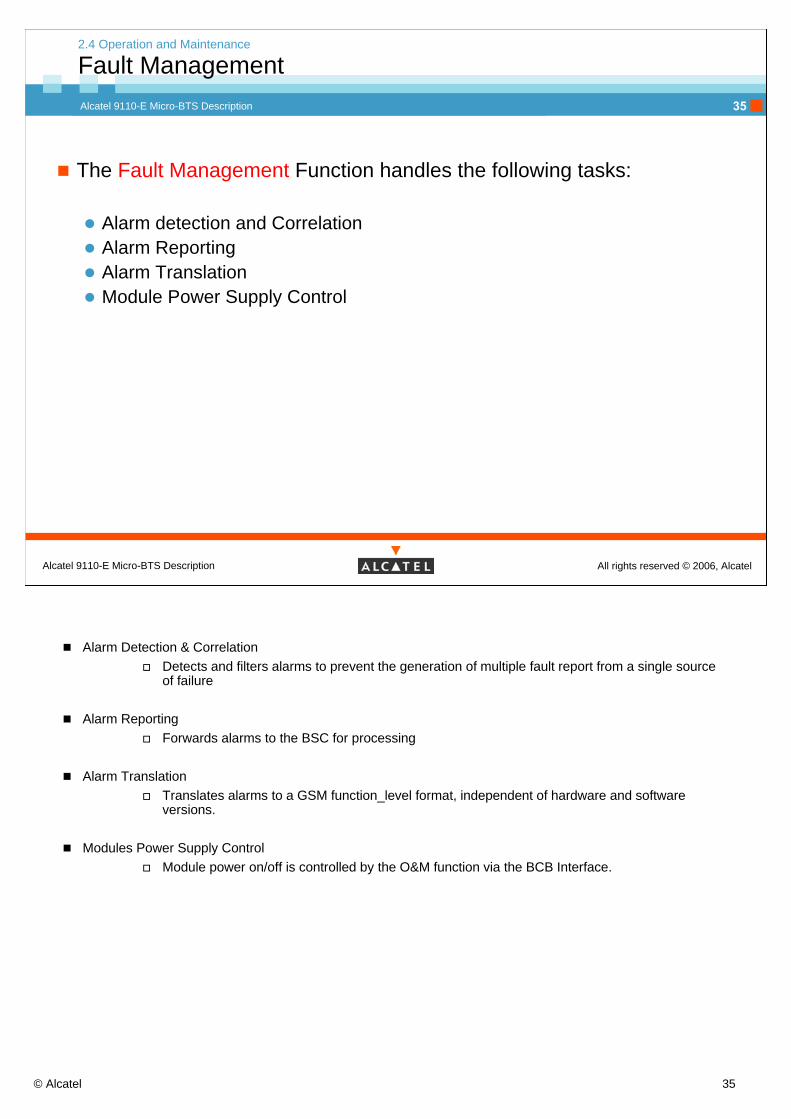
Alarm detection and CorrelationAlarm Reporting Alarm TranslationModule Power Supply Control
2.4 Operation and Maintenance
Fault Management
Alarm Detection & CorrelationDetects and filters alarms to prevent the generation of multiple fault report from a single source of failure
Alarm ReportingForwards alarms to the BSC for processing
Alarm TranslationTranslates alarms to a GSM function_level format, independent of hardware and software versions.
Modules Power Supply ControlModule power on/off is controlled by the O&M function via the BCB Interface.

© Alcatel 36
Alcatel 9110-E Micro-BTS Description
All rights reserved © 2006, AlcatelAlcatel 9110-E Micro-BTS Description
36
External Alarm Handling
External Alarm Connections provide a mechanical/electrical interface between the Dedicated Alarm and Control Handling function.
2.4 Operation and Maintenance
External alarm handling
External alarms:Each basic unit provides eight external alarm inputs. The connectors are located on the connection box.In a site configuration where several basic units are interconnected, it is possible to use the externalalarms of the master and of the slave basic units. Then the number of external alrms inputs regardingthe whole micro BTS site configuration can grow up to 48, depending on the number of basic units.

© Alcatel 37
Alcatel 9110-E Micro-BTS Description
All rights reserved © 2006, AlcatelAlcatel 9110-E Micro-BTS Description
37
2. Functional Architecture
2.5 Transmission
© Alcatel 38
Alcatel 9110-E Micro-BTS Description
All rights reserved © 2006, AlcatelAlcatel 9110-E Micro-BTS Description
38
2.5 Transmission
Functional architecture
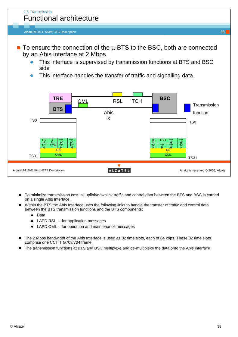
To ensure the connection of the µ-BTS to the BSC, both are connected by an Abis interface at 2 Mbps.
This interface is supervised by transmission functions at BTS and BSC sideThis interface handles the transfer of traffic and signalling data
TS0
OMLRSL
TCH TC
HTCHTCH
TCH
TCHTCH
TCH
TS31
TS0
OMLRSL
TCH TCH
TCHTCH
TCH
TCH
TCH
TCH
TS31
BTS
BSCOML RSL TCHTransmission
function
TRE
AbisX
To minimize transmission cost, all uplink/downlink traffic and control data between the BTS and BSC is carried on a single Abis Interface. Within the BTS the Abis Interface uses the following links to handle the transfer of traffic and control data between the BTS transmission functions and the BTS components:
DataLAPD RSL - for application messagesLAPD OML - for operation and maintenance messages
The 2 Mbps bandwidth of the Abis Interface is used as 32 time slots, each of 64 kbps. These 32 time slots comprise one CCITT G703/704 frame.The transmission functions at BTS and BSC multiplexe and de-multiplexe the data onto the Abis interface

© Alcatel 39
Alcatel 9110-E Micro-BTS Description
All rights reserved © 2006, AlcatelAlcatel 9110-E Micro-BTS Description
39
BTS
BTS
BTS
BTS
BTS
BTSBTS
BSC
Multipoint Configuration (Multidrop)
Chain Configuration
Star Configuration
Abis
Um
AbisPrimary
Abis
BTS
Satellite
2.5 Transmission
Topology
SecondaryAbis
Topology possible with the A9110-E µ-BTS
In case of BTS failure or power shutdown, the Abis link is not interruptedfor the following BTSs.
STAR topology: One PCM link connects only One BTS to BSC. Open Multi-drop topology “CHAIN”: One PCM link connects up to 15 BTS (only 1 TRE for each BTS and using the 16 Kbps Statistic multiplexing) in serial order and the PCM is not looped back to BSC by the last BTS.
In chain topology, the BSC is connected with Abis link to a BTS. This one is connected to a second BTS with a second Abis link, the second BTS is at its turn connected to a third one and so on.
Closed Multi-drop topology “RING”: One PCM link connects up to 7 BTS in serial order and the PCM is looped back to BSC by the last BTS.
In ring or loop topology, the last BTS of a chain is connected back to the BSC. This topology offers some security since traffic between any BTS and BSC is broadcast on the two paths, selection is based on dedicated Service bits / bytes.
Abis via satellite : BTS on satellite Abis links have the increased timers.(from B7)To increase the data throughputs (GPRS and EGPRS) over radio interface some Extra TS are needed. They can be present on the primary Abis which carries the Basic Time slots, but in case of full abis, another abiscalled Secondary abis can be added on the BTS. (The secondary Abis carries only Extra TS).

© Alcatel 40
Alcatel 9110-E Micro-BTS Description
All rights reserved © 2006, AlcatelAlcatel 9110-E Micro-BTS Description
40
2.5 Transmission
Signalling & traffic
SignallingSignalling frames are sent
via the RSL between the BSC and the baseband functionsOne RSL is required for each BTS carrier
Via the OML between the BSC and the O&M functionsOnly one OML is used by BTS
TrafficTime slots not used for signalling information are available to carry traffic. For this purpose, each 64 kbps slot is divided into four 16 kbps nibbles.
For TCH/F each time slot is shared between four full rate TCHsFor TCH/H each time slot is shared between eight half-rate TCHs
To optimise the number of time slots on the Abis link, it ’s possible to multiplex the signalling on a 64 Kbit/s.
No abis signalling multiplexing: each RSL has one 64 Kbits/s PCM channel.The Abis static signalling multiplexing: the RSLs of 4 TRXs are submultiplexed on one 64-kbits/s PCM channel.The Abis statistical signalling multiplexing on 64 Kbit/s channel: it enables the use of one to four RSLsand the OML on the same 64-kbits/s PCM channel.The Abis statistical signalling multiplexing on 16 Kbits/s channel: it enables the use of one RSL and the OML on the same 16-kbits/s PCM channel.
© Alcatel 41
Alcatel 9110-E Micro-BTS Description
All rights reserved © 2006, AlcatelAlcatel 9110-E Micro-BTS Description
41
2. Functional Architecture
2.6 Clock and power supply

© Alcatel 42
Alcatel 9110-E Micro-BTS Description
All rights reserved © 2006, AlcatelAlcatel 9110-E Micro-BTS Description
42
2.6 Clock and power supply
Functional architecture
The functions of the clock are:
Master clock generationfrom an external clock
Abis link (PCM synchronised)satellite
from an internal clock (free running)Timing signal generationClock distribution
The functions of the power supply are:
rectifyingpower distribution
Functions of the clock:Reference clock Generation
The A9110-E BTS clock is derived from a 13 MHz master reference frequency. The master frequency is generated by the master frequency generator. This is a high stability oscillator.The internal 13 MHz master frequency can be either free-running, or synchronized to the PCM clock on the Abis Interface. If the free-running mode is used, the BTS internal clock requires yearly calibration.Additionally, an external clock synchronization signal for the BTS can be provided by the XGPS option. This signal can be used to replace the PCM synchronization from the Abis Interface.
Timing Signal GenerationFrom the 13 MHz reference signal, the following slower synchronization clocks are derived by a process of frequency division:
2.167 MHz OBCLK216.7 Hz FCLK with Frame Number multiplexed.
Clock Distribution The Clock Distribution function distributes the synchronization clocks in the BTS.
Functions of the power supply:The A9110-E µ-BTS supports:
AC : 230 V (range from 170 V to 270 V)DC : 300 V (range from 240 V to 357 V)
The function is to rectify the voltage and distribute the power in the BTS.

© Alcatel 43
Alcatel 9110-E Micro-BTS Description
All rights reserved © 2006, AlcatelAlcatel 9110-E Micro-BTS Description
43
2. Functional Architecture
2.7 Remote Inventory and BSII interface

© Alcatel 44
Alcatel 9110-E Micro-BTS Description
All rights reserved © 2006, AlcatelAlcatel 9110-E Micro-BTS Description
44
2.7 Remote inventory and BSII interface
Functional architecture
SLAVE
SLAVE
MAN1or
MAN2Trans & ClockµP
Abis InterfaceTrans Switch
OMU
ISLPilot
ISL
ISL
ISL MTRE
MASTERMSUMBCB
BSIIOML/IOM/IOMConf
OMLTCHRSL IOM
IOM Conf
LNA Alarm
External Alarms
External Alarms
External Alarms
Abis
BTS-Term
Inter Entity Bus (IEB)
Remote inventory and BSII interfaceThe remote inventory system allows to store information as :
Serial number, Identification, Manufacturing, commissioning and repair dates, Site and customer names, configuration ... in EEPROM placed in the different modules of the equipment.These information are accessible from BTS terminal or from the OMC-R.
These EEPROM are managed by specific components (ISL) themselves controlled trough a BCB Bus.
Some alarms as External or Power supply alarms are also controlled by ISL and BCB.
All other useful information as traffic, signalling or control (TCH, RSL, OML, ...) use only one BSII bus.
In case of Master Slave configurations, Bsii and BCB are multiplexed in a specific Inter Entity Bus

© Alcatel 45
Alcatel 9110-E Micro-BTS Description
All rights reserved © 2006, AlcatelAlcatel 9110-E Micro-BTS Description
45
2. Functional architecture
Self-Assessment on the Objectives
Please be reminded to fill in the formSelf-Assessment on the Objectivesfor this moduleThe form can be found in the first partof this course documentation
Objective: to be able to identify the functional subsetsof the µ-BTS
© Alcatel 46
Alcatel 9110-E Micro-BTS Description
All rights reserved © 2006, AlcatelAlcatel 9110-E Micro-BTS Description
46
3. Hardware Architecture

© Alcatel 47
Alcatel 9110-E Micro-BTS Description
All rights reserved © 2006, AlcatelAlcatel 9110-E Micro-BTS Description
47
Hardware Architecture
Session presentation
Objective : to be able to identify the hardware modules of the A9110-E µ-BTS
Program : page number3.1 General architecture view of A9110-E µ-BTS 483.2 Basic unit 503.3 Connexion box (COBO) 523.4 Options 54
© Alcatel 48
Alcatel 9110-E Micro-BTS Description
All rights reserved © 2006, AlcatelAlcatel 9110-E Micro-BTS Description
48
3. Hardware Architecture
3.1 General architecture view of A9110-E µ-BTS

© Alcatel 49
Alcatel 9110-E Micro-BTS Description
All rights reserved © 2006, AlcatelAlcatel 9110-E Micro-BTS Description
49
3.1 General architecture view of A9110-E µ-BTS
Hardware Architecture
The Alcatel A9110-E µ-BTS is composed of :1 Basic unit (MB5x or DB5x)1 Connection box (COBO)1 Mounting frame (MOFRA) pole
A9110-E Micro BTS
installed on a pole
Mounting frameBASIC UNIT
COBO
MOCO=MOFRA+COBO

© Alcatel 50
Alcatel 9110-E Micro-BTS Description
All rights reserved © 2006, AlcatelAlcatel 9110-E Micro-BTS Description
50
3. Hardware Architecture
3.2 Basic unit

© Alcatel 51
Alcatel 9110-E Micro-BTS Description
All rights reserved © 2006, AlcatelAlcatel 9110-E Micro-BTS Description
51
The Basic unit is composed of:1 MSUMA2 (MTREDA and MTEPA)1 MAN1E or 1 MAN2E1 MPS2
According the frequency band and the type of MAN, the basic unit has a specific name:
EGSM 900, No Diversity
GSM 1800, No Diversity
GSM 1900, No Diversity
GSM 850, No Diversity
DescriptionBasic unit
MB5EMB5DMB5PMB5L
EGSM 900, with Diversity
GSM 1800, with Diversity
GSM 1900, with Diversity
GSM 850, with Diversity
DescriptionBasic unit
DB5EDB5DDB5PDB5L
The Basic unit is considered as a RIT:
If one element of the board is faulty
the basic unit has to be replaced
3.2 Basic Unit
Hardware Architecture
RIT: Replaceable ItemThe name of the RIT is written on the side of the basic unit.Diversity meaning:
No diversity: one antennaWith diversity: two antennas

© Alcatel 52
Alcatel 9110-E Micro-BTS Description
All rights reserved © 2006, AlcatelAlcatel 9110-E Micro-BTS Description
52
3. Hardware Architecture
3.3 Connexion box (COBO)

© Alcatel 53
Alcatel 9110-E Micro-BTS Description
All rights reserved © 2006, AlcatelAlcatel 9110-E Micro-BTS Description
53
LPEN
Abis 1 and 2
AC Input
AC OutputSlave 1
AC OutputSlave 2
IEB S1 IEB S2 Ext. Al
BASIC UNIT
ABISCO2 ACCO
Abis trace
Abis relays
Lightningprotection
BTSMM I
2 Abisinterface
3.3 Connection Box
Hardware Architecture
Connexion box (COBO) :The connection box is made of one waterproof area.It is divided into two separate chambers.
One contains the ABISCO2 board which interconnect the Alcatel 9110-E to the Abis link and provides the external alarms and the test interfaces.The second chamber provides the interconnection to mains (or site support cabinet for power) and distributes the power to the slave BTSs and to the external top fan. The ACCO board provides all external I/O within this chamber.
The COBO provides a set of clamp strips and connectors for the connexions to the outside and is linked to the MSUMA and the power supply MPS. This area can be divided into 3 subsets of connectors:
Power Supply AC clamp strips including protection and connector for top fan unit.Access to Abis 1 and 2 and overvoltage protection.Remote interfaces to provide external access to the MSUMA (external alarms, inter-entity bus, MMI, ...).
Power supplyThe Alcatel 9110-E Micro-BTS supports:
AC: 230 V (range from 170 V to 270 V).DC : 300 V (range from 240 V to 357 V)
The basic units are protected against short power failure of less than 200 ms.The slave units can be remotely fed from the master unit.
Descriptions of main interfaces:Abis trace: This interface is used to trace messages over the abis interface in operating modeBTS MMI: This serial interface is used for O&M and transmission purposes.External alarms:Eight lines are available to connect external alarms input.IEB: Inter Entity Bus is used for connecting master and slaves units only.External power supply: The external power supply is applied to the master unit only. Distribution to any slave unit is achieved using additional cables.
© Alcatel 54
Alcatel 9110-E Micro-BTS Description
All rights reserved © 2006, AlcatelAlcatel 9110-E Micro-BTS Description
54
3. Hardware Architecture
3.4 Options

© Alcatel 55
Alcatel 9110-E Micro-BTS Description
All rights reserved © 2006, AlcatelAlcatel 9110-E Micro-BTS Description
55
3.4 Options
Protection Cover
Protection cover
For each basic unit, Alcatel provides as an option, an appropriate protection cover. It will protect the BTS equipment against environmental impact (dirt, wind, sun radiation, etc.) and unauthorised access.
The use of the cover is recommended for Outdoor environments, or in case of aesthetics constraints in Indoor environments (public rooms).
The cover is made up of four parts:the back part, fixed with the mounting frame during the installation process,the front part,the top part,the bottom part, which gives the access to the connection box.
It is available in two variants:the “standard cover”,the “integrated-antenna cover” where the front part is modified.
The second variant is mandatory in case of choosing integrated antenna option.
If the fan option is chosen, the top part of the cover is replaced by another one in which fans are integrated.

© Alcatel 56
Alcatel 9110-E Micro-BTS Description
All rights reserved © 2006, AlcatelAlcatel 9110-E Micro-BTS Description
56
3.4 Options
Integrated FANS
Ext. Alarm in COBO
ACFAN in COBO
Integrated fans
The standard product is designed to support temperature up to +45°C. Fans are added for temperature up to +55°C.This option is a special top cover including:
a fan cassette (with 2 fans)a fan control boardAC and alarms cables
The speed of the fans is controlled depending on the temperature. In case of failure, an external alarm is sent to OMC-R. The replacement from the standard top cover to the special one (including the fans) is done on field during the installation process. The protection cover is mandatory when using fans.

© Alcatel 57
Alcatel 9110-E Micro-BTS Description
All rights reserved © 2006, AlcatelAlcatel 9110-E Micro-BTS Description
57
3.4 Options
Integrated antenna
Hole inthe cover
Fixed on the
unit itself
Connected on antenna outputs
Integrated antenna
The integrated antenna is possible only in low-loss configuration.If a basic unit of micro BTS uses integrated antenna, then all other basics units must use integrated antenna.Integrated antennas use the same connector as external antennas.It’s mounted on the front face of the basic unit.A special cover is required for this option.

© Alcatel 58
Alcatel 9110-E Micro-BTS Description
All rights reserved © 2006, AlcatelAlcatel 9110-E Micro-BTS Description
58
3.4 Options
VSWR Detectors
BASIC UNIT
5 v output(on GPS point)
External alarmsinputs
Jumpers
VSWR(Voltage Standing Wave Ratio) Detectors
The return loss of the transmitted signal can be measured at the antenna connector thanks to the VSWR meter option.It’s a separated device which is introduced between Antenna connector and the antenna feeder therefore located inside the protection cover.
These detectors must be powered (GPS 5V on ABISCO) and connected to external alarms following installation procedure.This option is possible and available in EGSM900. It’s not possible to use it together with the integrated antenna option.
© Alcatel 59
Alcatel 9110-E Micro-BTS Description
All rights reserved © 2006, AlcatelAlcatel 9110-E Micro-BTS Description
59
3.4 Options
HDSL Equipment
A9110
SSC
A9110
SSC
A9110
SSC
A9110
SSC
A9110
SSC
A9110
SSC
ExternalHDSL equipment
HDSLequipmentinside Site Support Cabinet
1 pair, 0.6 mmd < 3.2 Km
1 pair, 0.8 mmd < 4.9 Km1 pair, 0.4 mm
d < 1.9 Km
HDSL
OMC-R
BSC
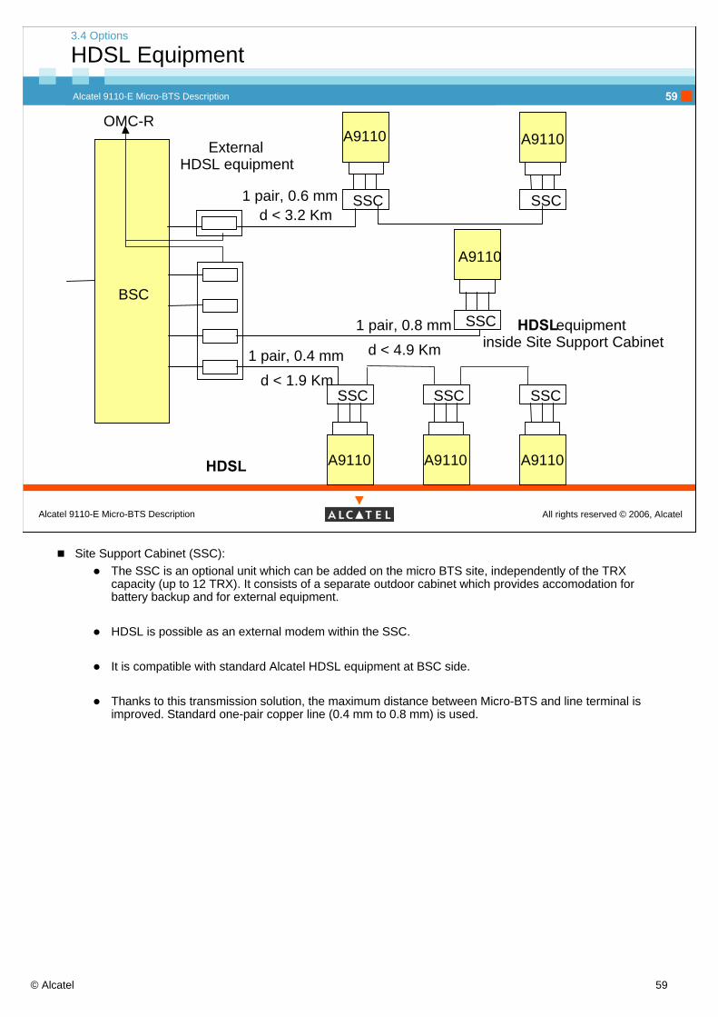
Site Support Cabinet (SSC):The SSC is an optional unit which can be added on the micro BTS site, independently of the TRX capacity (up to 12 TRX). It consists of a separate outdoor cabinet which provides accomodation for battery backup and for external equipment.
HDSL is possible as an external modem within the SSC.
It is compatible with standard Alcatel HDSL equipment at BSC side.
Thanks to this transmission solution, the maximum distance between Micro-BTS and line terminal is improved. Standard one-pair copper line (0.4 mm to 0.8 mm) is used.

© Alcatel 60
Alcatel 9110-E Micro-BTS Description
All rights reserved © 2006, AlcatelAlcatel 9110-E Micro-BTS Description
60
3. Hardware Architecture
Self-Assessment on the Objectives
Please be reminded to fill in the formSelf-Assessment on the Objectivesfor this module
The form can be found in the first partof this course documentation
Objective: to be able to identify the hardware modules of the µ-BTS
© Alcatel 61
Alcatel 9110-E Micro-BTS Description
All rights reserved © 2006, AlcatelAlcatel 9110-E Micro-BTS Description
61
4. Configurations
© Alcatel 62
Alcatel 9110-E Micro-BTS Description
All rights reserved © 2006, AlcatelAlcatel 9110-E Micro-BTS Description
62
4. Configurations
Session presentation
Objective : to be able to identify the possible hardware configurations
Program : page number4.1 Site configuration 634.2 Basic configuration 654.3 Single antenna configuration 674.4 Low loss configuration 694.5 Multiband configuration 71

© Alcatel 63
Alcatel 9110-E Micro-BTS Description
All rights reserved © 2006, AlcatelAlcatel 9110-E Micro-BTS Description
63
4. Configurations
4.1 Site configuration

© Alcatel 64
Alcatel 9110-E Micro-BTS Description
All rights reserved © 2006, AlcatelAlcatel 9110-E Micro-BTS Description
64
4.1 Site configuration
Configurations
M5M
M5M
M5M
M5M
M5MM5M
UpperSlavelevel
Lower Slavelevel
M5M
Master
Slave 2Slave 1
Slave 11 Slave 12 Slave 21 Slave 22
External AlarmsPowerAbis
External Alarms External Alarms
ExternalAlarms
ExternalAlarms
ExternalAlarms
ExternalAlarms
Power supplyInter-entity bus
The maximum capacity is 6 basic units for one 12 TRX
Slave or master basic units are identical from a hardware point of view but, all base station control functions are activated in the master unit only.4 configurations are defined for pure M5M and M4M/M5M mixed configurations:
Maximum 3 hierarchy levels (Master, Upper and lower slave) allowedM5M must be taken as Master in M4M/M5M mixed configurationM4M not possible in lower slave positionEach M4M as upper Slave terminates the Master-Slave-Link (inter Entity Bus - IEB)

© Alcatel 65
Alcatel 9110-E Micro-BTS Description
All rights reserved © 2006, AlcatelAlcatel 9110-E Micro-BTS Description
65
4. Configurations
4.2 Basic configuration

© Alcatel 66
Alcatel 9110-E Micro-BTS Description
All rights reserved © 2006, AlcatelAlcatel 9110-E Micro-BTS Description
66
4.2 Basic configuration
Possible configurations of the Evolium A9110-E Micro BTS
GSM 850 2TRX
GSM 850 2TRX
GSM 900 (EGSM band) 2TRX
GSM 900 (EGSM band) 2TRX
Description Antenna network architecture
GSM 1800 2TRX
GSM 1800 2TRX
GSM 1900 2TRX
GSM 1900 2TRX
Single Antenna
Low loss
Single Antenna
Low loss
Single Antenna
Low loss
Single Antenna
Low loss
No. of Antennas
1
2
1
2
1
2
1
2
Possible configurations of the Evolium A9110-E Micro BTS
© Alcatel 67
Alcatel 9110-E Micro-BTS Description
All rights reserved © 2006, AlcatelAlcatel 9110-E Micro-BTS Description
67
4. Configurations
4.3 Single antenna configuration

© Alcatel 68
Alcatel 9110-E Micro-BTS Description
All rights reserved © 2006, AlcatelAlcatel 9110-E Micro-BTS Description
68
4.3 Single antenna configuration
Single antenna configuration
1sector 2 sectors 3 sectors
No. of TRX
No. of basic unitsper sector
No. of antennas
TX output power
Up to 12
Up to 6
1/ basic unit
Deduced frombasic unit choice
Up to 6 TREsper sector
Up to 3
1/ basic unit
Deduced frombasic unit choice
Up to 4 TREsper sector
Up to 2
1/ basic unit
Deduced frombasic unit choice
A 9110-E single antennaconfigurations
Single antenna configuration
© Alcatel 69
Alcatel 9110-E Micro-BTS Description
All rights reserved © 2006, AlcatelAlcatel 9110-E Micro-BTS Description
69
4. Configurations
4.4 Low loss configuration

© Alcatel 70
Alcatel 9110-E Micro-BTS Description
All rights reserved © 2006, AlcatelAlcatel 9110-E Micro-BTS Description
70
4.4 Low loss configuration
Low loss configuration with antenna diversity
1sector 2 sectors 3 sectors
No. of TRX
No. of basic unitsper sector
No. of antennas
TX output power
Up to 12
Up to 6
2/ basic unit
Deduced frombasic unit choice
Up to 6 TREsper sector
Up to 3
2/ basic unit
Deduced frombasic unit choice
Up to 4 TREsper sector
Up to 2
2/ basic unit
Deduced frombasic unit choice
A 9110-E low lossconfigurations withantenna diversity
Low loss configuration with antenna diversity
The exact number of antennas depends on the use of panel/ cross-polarized/integrated antennas.

© Alcatel 71
Alcatel 9110-E Micro-BTS Description
All rights reserved © 2006, AlcatelAlcatel 9110-E Micro-BTS Description
71
4. Configurations
4.5 Multiband configuration

© Alcatel 72
Alcatel 9110-E Micro-BTS Description
All rights reserved © 2006, AlcatelAlcatel 9110-E Micro-BTS Description
72
4.5 Multiband configuration
Multiband BTS without multiband cell configurations
No. of TRX
No. of basic units
per sector
No. of antennas
TX output power
Deduced from basic unit choice
3 sectors x 2 TRX in Band 1
3 sectors x 2 TRX in Band 2
Band 1: 6 TRX (3x2)
Band 2: 6 TRX (3x2)
Band 1: 3 basic units
Band 2: 3 basic units
Deduced from basic unit choice
A 9110-E multibandBTS configuration
Multiband BTS without multiband cell configurations-Dual BCCH sectors may be either GSM 850, GSM 900, GSM 1800 or GSM 1900
Example: up to maximum 6 sectors configurable
A micro-BTS can be composed of basic units of each band. Both bands are assigned in different sectors (one BCCH for each band-dual BCCH) or in the same sector (one BCCH for both bands-single BCCH).
Both antenna network types (low loss and single antenna) are possible in multiband configurations.A mix of low-loss and single antenna networks in the same configuration (same sector) is not allowed.Multiband Configurations:
Multiband BTS without multiband cell configurations-Dual BCCH:The sectors may be either GSM 850, GSM 900, GSM1800 or GSM 1900.
Multiband BTS with multiband cell configurations-single BCCH:The possible multiband BTS with multiband cell configurations will be defined in further step.

© Alcatel 73
Alcatel 9110-E Micro-BTS Description
All rights reserved © 2006, AlcatelAlcatel 9110-E Micro-BTS Description
73
4. Configurations
Self-Assessment on the Objectives
Please be reminded to fill in the formSelf-Assessment on the Objectivesfor this module
The form can be found in the first partof this course documentation
Objective: to be able to identify the possible hardware configurations of the µ-BTS

© Alcatel 74
Alcatel 9110-E Micro-BTS Description
All rights reserved © 2006, AlcatelAlcatel 9110-E Micro-BTS Description
74
5. Appendix and Glossary

© Alcatel 75
Alcatel 9110-E Micro-BTS Description
All rights reserved © 2006, AlcatelAlcatel 9110-E Micro-BTS Description
75
5. Appendix
LEDs meaning and connector details
Mechanical assembly of ABISCO2

© Alcatel 76
Alcatel 9110-E Micro-BTS Description
All rights reserved © 2006, AlcatelAlcatel 9110-E Micro-BTS Description
76
5. Appendix
LEDs meaning and connector details

© Alcatel 77
Alcatel 9110-E Micro-BTS Description
All rights reserved © 2006, AlcatelAlcatel 9110-E Micro-BTS Description
77
5. Appendix
LEDs meaning and connector details

© Alcatel 78
Alcatel 9110-E Micro-BTS Description
All rights reserved © 2006, AlcatelAlcatel 9110-E Micro-BTS Description
78
Glossary
A Interface between TC and NSS ABIS Interface between the BTS and The BSCAC Alternating CurrentAN Antenna NetworkAtermux Interface between BSC and TC or MFSBSC Base Station ControllerBTS Base Transceiver StationCCITT International consultative committee on telecommunications and TelegraphyCOBO Connection BoxDC Direct CurrentDCS Digital Cellular SystemDR Dual RateEEPROM Electrically Erasable Programmable Read Only MemoryEFR Enhanced Full Rate codecE-PGSM Extended-band GSMFR Full RateGb Interface between the equipment supporting the PCU function and the GPRS Core NetworkGMSK Gaussian Minimum Shift Keying modulationGPRS General Packet Radio ServicesGSM Global System for Mobile CommunicationHDSL High speed Digital Subscriber LoopHR Half RateIEB Inter Entity BUSISL Internal Serial LinkLNA Low Noise AmplifierMAN Micro-BTS Antenna NetworkMMI Man Machine InterfaceMFS Multi-BSS Fast Packet ServerMPS2 Micro-BTS Power SupplyMSUMA Micro-BTS Station Unit ModuleMTRE Micro-BTS TRansceiver Equipment
© Alcatel 79
Alcatel 9110-E Micro-BTS Description
All rights reserved © 2006, AlcatelAlcatel 9110-E Micro-BTS Description
79
Glossary
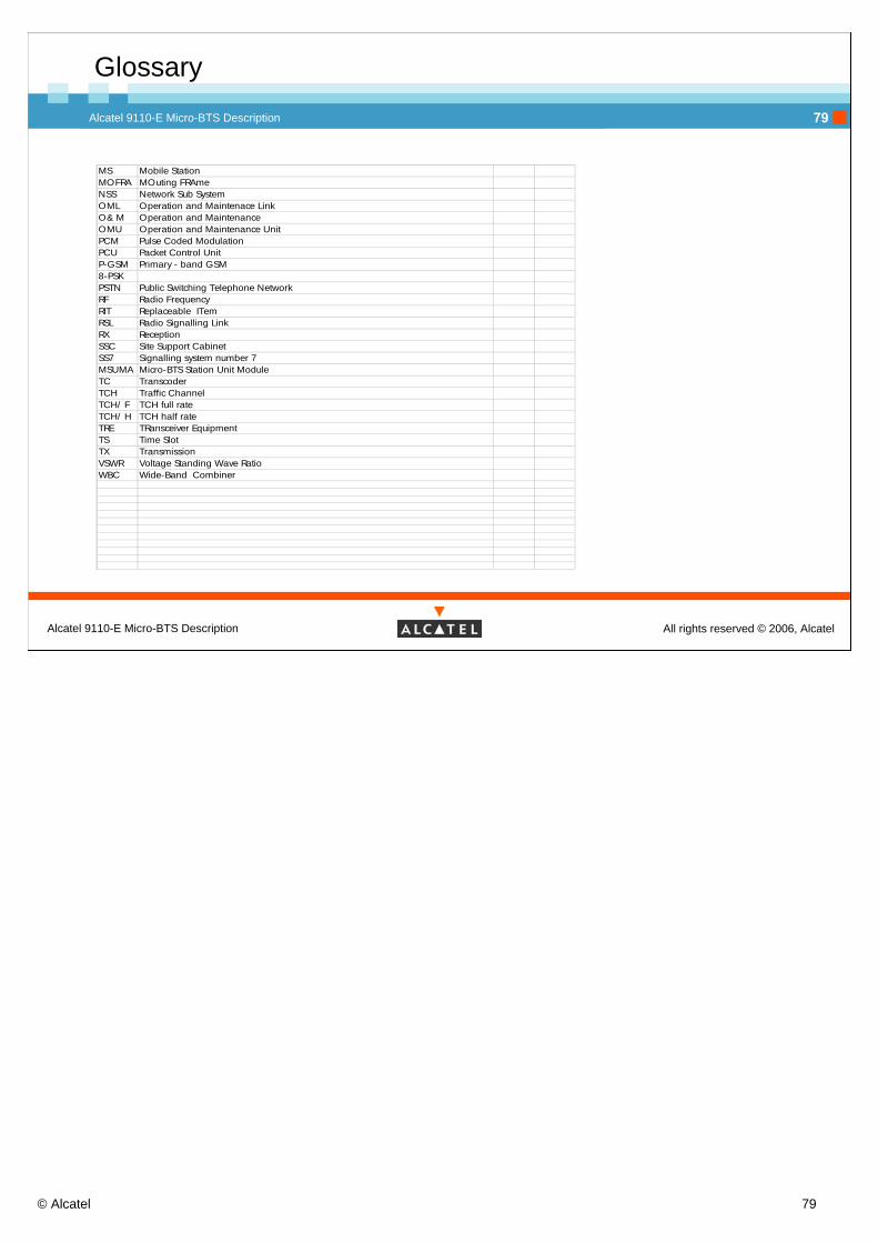
MS Mobile StationMOFRA MOuting FRAme NSS Network Sub SystemOML Operation and Maintenace LinkO& M Operation and MaintenanceOMU Operation and Maintenance UnitPCM Pulse Coded ModulationPCU Packet Control UnitP-GSM Primary - band GSM8-PSKPSTN Public Switching Telephone NetworkRF Radio FrequencyRIT Replaceable ITemRSL Radio Signalling LinkRX ReceptionSSC Site Support CabinetSS7 Signalling system number 7MSUMA Micro-BTS Station Unit ModuleTC TranscoderTCH Traffic ChannelTCH/ F TCH full rateTCH/ H TCH half rateTRE TRansceiver EquipmentTS Time SlotTX TransmissionVSWR Voltage Standing Wave RatioWBC Wide-Band Combiner

© Alcatel 80
Alcatel 9110-E Micro-BTS Description
All rights reserved © 2006, AlcatelAlcatel 9110-E Micro-BTS Description
80
Top Related