


Languages
Pages
Legal

https://edocs.imo.org/Final Documents/English/MEPC 68-INF-30 (E).docx
E
MARINE ENVIRONMENT PROTECTION COMMITTEE 68th session Agenda item 3
MEPC 68/INF.30
6 March 2015 ENGLISH ONLY
AIR POLLUTION AND ENERGY EFFICIENCY
2015 industry guidelines on calculation and verification of the
Energy Efficiency Design Index (EEDI)
Submitted by IACS, INTERTANKO, ITTC and OCIMF
SUMMARY
Executive summary: This document provides at the annex a copy of the 2015 industry guidelines for calculation and verification of the Energy Efficiency Design Index (EEDI) requirements and the role of the verifier in conducting the verification of EEDI
Strategic direction: 7.3
High-level action: 7.3.2
Planned output: 7.3.2.1
Action to be taken: Paragraph 2
Related documents: MEPC 62/5/21; MEPC 64/4/32, MEPC 64/INF.22 and MEPC 68/3/14
Introduction 1 As discussed in document MEPC 68/3/14, the annex to this document provides the 2015 version of the industry guidelines for calculation and verification of the Energy Efficiency Design Index (EEDI), covering all ship and propulsion types as well as innovative saving devices and major conversions that are within the scope of the MARPOL Annex VI amendments on energy efficiency adopted by resolution MEPC.251(66). Action requested of the Committee
2 The Committee is invited to note the 2015 version of the industry guidelines for calculation and verification of the Energy Efficiency Design Index (EEDI), as set out in the annex.
***
MEPC 68/INF.30 Annex, page 1
https://edocs.imo.org/Final Documents/English/MEPC 68-INF-30 (E).docx
ANNEX
2015 INDUSTRY GUIDELINES FOR CALCULATION AND VERIFICATION OF THE ENERGY
EFFICIENCY DESIGN INDEX (EEDI)
TABLE OF CONTENTS
PART I – SCOPE OF THE INDUSTRY GUIDELINES
1 Scope of the Guidelines ................................................................................................. 2
PART II – EXPLANATORY NOTES ON CALCULATION OF EEDI
2 Introduction .................................................................................................................... 4
3 EEDI formula for CO2 emission ...................................................................................... 4
4 Fuel consumption and fuel conversion factor .................................................................. 4
5 Capacity, power and speed ............................................................................................ 5
6 Shaft generator and shaft motor ..................................................................................... 6
7 Weather factor fw ...........................................................................................................12
8 Correction factor for ship specific design elements fj .....................................................12
9 Capacity factor fi ............................................................................................................13
10 Cubic capacity correction factor fc AND cargo gears FACTOR fl .................................13
11 Innovative energy efficient technologies .......................................................................13
12 Example of calculation ..................................................................................................13
PART III – VERIFICATION OF EEDI
13 Verification process ......................................................................................................16
14 Documents to be submitted ..........................................................................................16
15 Preliminary verification at the design stage ...................................................................18
16 Final verification at sea trial ..........................................................................................22
17 Verification of the EEDI in case of major conversion .....................................................24
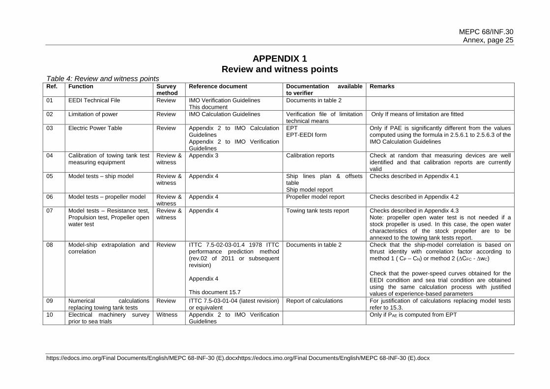
1 Appendix 1. Review and witness points .........................................................................26
2 Appendix 2. Sample of document to be submitted to the verifier ...................................28
3 Appendix 3. Verifying the calibration of model test equipement .....................................42
4 Appendix 4. Review and witnessing of model test procedures ......................................48
5 Appendix 5. Sample report "preliminary verification of EEDI" ........................................56
6 Appendix 6. Sample calculations of EEDI ......................................................................57
MEPC 68/INF.30 Annex, page 2
https://edocs.imo.org/Final Documents/English/MEPC 68-INF-30 (E).docx
Part I – Scope of the Industry Guidelines
1 Scope of the Guidelines
1.1 Objective The objective of these Industry Guidelines for calculation and verification of the Energy Efficiency Design Index (EEDI), hereafter designated as "the Industry Guidelines", is to provide details and examples of calculation of attained EEDI and to support the method and role of the verifier in charge of conducting the survey and certification of EEDI in compliance with the following IMO Resolutions:
2014 Guidelines on the method of calculation of EEDI for new ships, Res. MEPC.245(66) adopted on 4 April 2014, referred to as the "IMO Calculation Guidelines" in the present document
2014 Guidelines on survey and certification of EEDI, Res. MEPC.254(67) adopted on 17 October 2014, referred to as the "IMO Verification Guidelines" in the present document
2013 interim Guidelines for determining minimum propulsion power to maintain the manoeuvrability of ships in adverse conditions, Res. MEPC.232(65) as amended by Res. MEPC.255(67) on 17 October 2014
2013 Guidance on treatment of innovative energy efficiency technologies for calculation and verification of the attained EEDI, MEPC.1/Circ.815
In the event that the IMO Guidelines are amended, then pending amendment of these Industry Guidelines, calculation and verification of EEDI are to be implemented in compliance with the amended IMO Guidelines. 1.2 Application These Guidelines apply to new ships as defined in regulation 2.23 of MARPOL Annex VI of 400 gross tonnage and above of the types defined in regulations 2.25 to 2.31, 2.33 to 2.35, 2.38 and 2.39, as follows:
Bulk carrier
Gas carrier
LNG carrier (contracted on or after 1 September 2015)
Cruise passenger ship having non-conventional propulsion (contracted on or after 1 September 2015)
Tanker
Container ship
General cargo ship
Ro-ro cargo ship (vehicle carrier) (contracted on or after 1 September 2015)
Ro-ro cargo ship (contracted on or after 1 September 2015)
Ro-ro passenger ship (contracted on or after 1 September 2015)
Refrigerated cargo carrier
Combination carrier The calculation and verification of EEDI shall be performed for each:
1. new ship before ship delivery 2. new ship in service which has undergone a major conversion 3. new or existing ship which has undergone a major conversion that is so extensive
that the ship is regarded by the Administration as a newly constructed ship The Industry Guidelines shall not apply to ships which have non-conventional propulsion, such as diesel-electric propulsion, turbine propulsion or hybrid propulsion systems, with the

MEPC 68/INF.30 Annex, page 3
https://edocs.imo.org/Final Documents/English/MEPC 68-INF-30 (E).docxhttps://edocs.imo.org/Final Documents/English/MEPC 68-INF-30 (E).docx
exception of cruise passenger ships with diesel-electric propulsion and LNG carriers having diesel-electric or steam turbine propulsion systems. The Industry Guidelines shall not apply to cargo ships having ice-breaking capability as defined in regulation 2.42 of MARPOL Annex VI. As a consequence, the Industry Guidelines apply to cargo vessels with ice class up to and including Finnish-Swedish ice class 1A Super or equivalent unless they qualify as a ship with ice-breaking capability in which case they are exempt. The intermediate Polar Classes, namely PC4 and PC5, need to demonstrate ice-breaking capability through ice trials to qualify. In the initial stages, ice-breaking capability can be demonstrated based on ice tank tests.
***
MEPC 68/INF.30 Annex, page 4
https://edocs.imo.org/Final Documents/English/MEPC 68-INF-30 (E).docx
Part II – Explanatory notes on calculation of EEDI
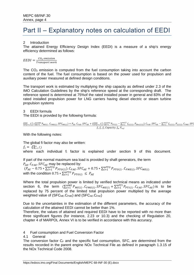
2 Introduction The attained Energy Efficiency Design Index (EEDI) is a measure of a ship's energy efficiency determined as follows:
𝐸𝐸𝐷𝐼 =𝐶𝑂2 𝑒𝑚𝑖𝑠𝑠𝑖𝑜𝑛
𝑇𝑟𝑎𝑛𝑠𝑝𝑜𝑟𝑡 𝑤𝑜𝑟𝑘
The CO2 emission is computed from the fuel consumption taking into account the carbon content of the fuel. The fuel consumption is based on the power used for propulsion and auxiliary power measured at defined design conditions. The transport work is estimated by multiplying the ship capacity as defined under 2.3 of the IMO Calculation Guidelines by the ship's reference speed at the corresponding draft. The reference speed is determined at 75%of the rated installed power in general and 83% of the rated installed propulsion power for LNG carriers having diesel electric or steam turbine propulsion systems 3 EEDI formula The EEDI is provided by the following formula: (∏ 𝑓𝑗
𝑛𝑗=1 ). (∑ 𝑃𝑀𝐸(𝑖)
𝑛𝑀𝐸𝑖=1 . 𝐶𝐹𝑀𝐸(𝑖). 𝑆𝐹𝐶𝑀𝐸(𝑖)) + 𝑃𝐴𝐸 . 𝐶𝐹𝐴𝐸 . 𝑆𝐹𝐶𝐴𝐸 + {(∏ 𝑓𝑗
𝑛𝑗=1 ). ∑ 𝑃𝑃𝑇𝐼(𝑖) − ∑ 𝑓𝑒𝑓𝑓(𝑖). 𝑃𝐴𝐸𝑒𝑓𝑓(𝑖)}. 𝐶𝐹𝐴𝐸 . 𝑆𝐹𝐶𝐴𝐸 − ∑ 𝑓𝑒𝑓𝑓(𝑖). 𝑃𝑒𝑓𝑓(𝑖). 𝐶𝐹𝑀𝐸 . 𝑆𝐹𝐶𝑀𝐸)
𝑛𝑒𝑓𝑓𝑖=1
𝑛𝑒𝑓𝑓𝑖=1
𝑛𝑃𝑇𝐼𝑖=1
𝑓𝑖. 𝑓𝑐. 𝑓𝑙 . 𝐶𝑎𝑝𝑎𝑐𝑖𝑡𝑦. 𝑓𝑤 . 𝑉𝑟𝑒𝑓
With the following notes: The global fi factor may also be written: 𝑓𝑖 = (∏ 𝑓
𝑖
𝑚𝑖=1 )
where each individual fi factor is explained under section 9 of this document. If part of the normal maximum sea load is provided by shaft generators, the term 𝑃𝐴𝐸 . 𝐶𝐹𝐴𝐸 . 𝑆𝐹𝐶𝐴𝐸 may be replaced by:
(𝑃𝐴𝐸 − 0.75 ∗ ∑ 𝑃𝑃𝑇𝑂(𝑖)𝑛𝑃𝑇𝑂𝑖=1 ). 𝐶𝐹𝐴𝐸 . 𝑆𝐹𝐶𝐴𝐸 + 0.75 ∗ ∑ 𝑃𝑃𝑇𝑂(𝑖)
𝑛𝑃𝑇𝑂𝑖=1 . 𝐶𝐹𝑀𝐸(𝑖). 𝑆𝐹𝐶𝑀𝐸(𝑖)
with the condition 0.75 ∗ ∑ 𝑃𝑃𝑇𝑂(𝑖)𝑛𝑃𝑇𝑂𝑖=1 ≤ 𝑃𝐴𝐸
Where the total propulsion power is limited by verified technical means as indicated under
section 6, the term (∑ 𝑃𝑀𝐸(𝑖)𝑛𝑀𝐸𝑖=1 . 𝐶𝐹𝑀𝐸(𝑖). 𝑆𝐹𝐶𝑀𝐸(𝑖) + ∑ 𝑃𝑃𝑇𝐼(𝑖)
𝑛𝑃𝑇𝐼𝑖=1 . 𝐶𝐹𝐴𝐸 . 𝑆𝐹𝐶𝐴𝐸) is to be
replaced by 75 percent of the limited total propulsion power multiplied by the average weighted value of (SFCME.CFME) and (SFCAE.CFAE) Due to the uncertainties in the estimation of the different parameters, the accuracy of the calculation of the attained EEDI cannot be better than 1%. Therefore, the values of attained and required EEDI have to be reported with no more than three significant figures (for instance, 2.23 or 10.3) and the checking of Regulation 20, chapter 4 of MARPOL Annex VI is to be verified in accordance with this accuracy. 4 Fuel consumption and Fuel Conversion Factor 4.1 General The conversion factor CF and the specific fuel consumption, SFC, are determined from the results recorded in the parent engine NOx Technical File as defined in paragraph 1.3.15 of the NOx Technical Code 2008.

MEPC 68/INF.30 Annex, page 5
https://edocs.imo.org/Final Documents/English/MEPC 68-INF-30 (E).docxhttps://edocs.imo.org/Final Documents/English/MEPC 68-INF-30 (E).docx
The fuel grade used during the test of the engine in the test bed measurement of SFC determines the value of the CF conversion factor according to the table under 2.1of the IMO Calculation Guidelines. SFC is the corrected specific fuel consumption, measured in g/kWh, of the engines. The subscripts ME(i) and AE(i) refer to the main and auxiliary engine(s), respectively. SFCAE is the power-weighted average among SFCAE(i) of the respective engines i. For main engines certified to the E2 or E3 test cycles of the NOx Technical Code 2008, the engine Specific Fuel Consumption (SFCME(i)) is that recorded in the test report included in a NOx Technical File for the parent engine(s) at 75% of MCR power. For engines certified to the D2 or C1 test cycles of the NOx Technical Code 2008, the engine Specific Fuel Consumption (SFCAE(i)) is that recorded in the test report included in a NOx Technical File for the parent engine(s) at 50% of MCR power or torque rating. The SFC is to be corrected to the value corresponding to the ISO standard reference conditions using the standard lower calorific value of the fuel oil (42,700kJ/kg), referring to ISO 15550:2002 and ISO 3046-1:2002. For LNG driven engines for which SFC is measured in kJ/kWh, the SFC value is to be converted to g/kWh using the standard lower calorific value of the LNG (48,000 kJ/kg), referring to the 2006 IPCC Guidelines. For those engines which do not have a test report included in a NOx Technical File because its power is below 130 kW, the SFC specified by the manufacturer is to be used. At the design stage, in case of unavailability of test reports in the NOx Technical File, the SFC value given by the manufacturer with the addition of the guarantee tolerance is to be used. 4.2 Dual-fuel engines Gas fuel may be used as primary fuel for one or more of the main and auxiliary engine(s) in accordance with paragraph 4.2.3 of the IMO Verification Guidelines. For these dual-fuel engines, the CF factor and the Specific Fuel Consumption for gas (LNG) and for pilot fuel should be combined at the relevant EEDI load point as described in 2.5.1 and Appendix 4 of the IMO Calculation Guidelines. 4.3 LNG carriers with steam turbine propulsion The Specific Fuel Consumption of the steam turbine should be determined during the running tests of the main boilers and steam turbines on board under load during the sea trials. For preliminary estimate of EEDI, manufacturer's certificate is to be used. 5 Capacity, power and speed 5.1 Capacity The capacity of the ship is computed as a function of the gross tonnage for cruise passenger ships and of the deadweight for other types of ships as indicated under 2.3 of the IMO Calculation Guidelines. For the computation of the deadweight according to 2.4 of the IMO Calculation Guidelines, the lightweight of the ship and the displacement at the summer load draught are to be based on the results of the inclining test or lightweight check provided in the final stability booklet. At the design stage, the deadweight may be taken in the provisional documentation.
MEPC 68/INF.30 Annex, page 6
https://edocs.imo.org/Final Documents/English/MEPC 68-INF-30 (E).docx
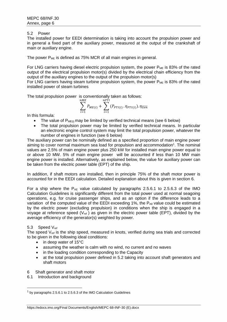
5.2 Power The installed power for EEDI determination is taking into account the propulsion power and in general a fixed part of the auxiliary power, measured at the output of the crankshaft of main or auxiliary engine. The power PME is defined as 75% MCR of all main engines in general. For LNG carriers having diesel electric propulsion system, the power PME is 83% of the rated output of the electrical propulsion motor(s) divided by the electrical chain efficiency from the output of the auxiliary engines to the output of the propulsion motor(s) For LNG carriers having steam turbine propulsion system, the power PME is 83% of the rated installed power of steam turbines The total propulsion power is conventionally taken as follows:
∑ 𝑃𝑀𝐸(𝑖)
𝑛𝑀𝐸
𝑖=1
+ ∑ (𝑃𝑃𝑇𝐼(𝑖)
𝑛𝑃𝑇𝐼
𝑖=1
. 𝜂𝑃𝑇𝐼(𝑖)). 𝜂𝐺𝑒𝑛̅̅ ̅̅ ̅̅
In this formula:
The value of PME(i) may be limited by verified technical means (see 6 below)
The total propulsion power may be limited by verified technical means. In particular an electronic engine control system may limit the total propulsion power, whatever the number of engines in function (see 6 below)
The auxiliary power can be nominally defined as a specified proportion of main engine power aiming to cover normal maximum sea load for propulsion and accommodation1. The nominal values are 2.5% of main engine power plus 250 kW for installed main engine power equal to or above 10 MW. 5% of main engine power will be accounted if less than 10 MW main engine power is installed. Alternatively, as explained below, the value for auxiliary power can be taken from the electric power table (EPT) of the ship. In addition, if shaft motors are installed, then in principle 75% of the shaft motor power is accounted for in the EEDI calculation. Detailed explanation about this is given in section 6. For a ship where the PAE value calculated by paragraphs 2.5.6.1 to 2.5.6.3 of the IMO Calculation Guidelines is significantly different from the total power used at normal seagoing operations, e.g. for cruise passenger ships, and as an option if the difference leads to a variation of the computed value of the EEDI exceeding 1%, the PAE value could be estimated by the electric power (excluding propulsion) in conditions when the ship is engaged in a voyage at reference speed (Vref ) as given in the electric power table (EPT), divided by the average efficiency of the generator(s) weighted by power. 5.3 Speed Vref The speed Vref is the ship speed, measured in knots, verified during sea trials and corrected to be given in the following ideal conditions:
in deep water of 15°C
assuming the weather is calm with no wind, no current and no waves
in the loading condition corresponding to the Capacity
at the total propulsion power defined in 5.2 taking into account shaft generators and shaft motors
6 Shaft generator and shaft motor 6.1 Introduction and background
1 by paragraphs 2.5.6.1 to 2.5.6.3 of the IMO Calculation Guidelines

MEPC 68/INF.30 Annex, page 7
https://edocs.imo.org/Final Documents/English/MEPC 68-INF-30 (E).docxhttps://edocs.imo.org/Final Documents/English/MEPC 68-INF-30 (E).docx
As for 2.5.2 and 2.5.3 of IMO Calculation Guidelines, content of this section applies to ships other than LNG carriers having diesel-electric propulsion system. For LNG carriers with diesel-electric propulsion, the factor 0.75 between the propulsion power and the rated power is to be replaced by 0.83 Ships need electrical power for the operation of engine auxiliary systems, other systems, crew accommodation and for any cargo purposes. This electrical power can be generated by diesel-generator sets (gen-sets), shaft generators, waste heat recovery systems driving a generator and possibly by new innovative technologies, e.g. solar panels. Diesel-generator sets and shaft generators are the most common systems. While diesel-generator sets use a diesel engine powering a generator, a shaft generator is driven by the main engine. It is considered that due to the better efficiency of the main engine and efficiency of the shaft generator less CO2 is emitted compared to gen-set operation. The EEDI formula expresses the propulsion power of a vessel as 75% of the main engine power PME. It is also termed shaft power PS, which corresponds to the ship's speed Vref in the EEDI formula. PAE - the auxiliary power - is also included in the EEDI formula. However, this power demand is largely dependent on loading and trading patterns and it must also incorporate safety aspects, for example, the provision of a spare generator set. As noted in section 5, the auxiliary power can generally be taken into account as a fixed proportion of the main engine power (i.e. nominally 2.5% plus 250kW)2. The use of shaft generators is a well proven and often applied technology, particularly for high electrical power demands related to the payload e.g. reefer containers. Usually a ship design implements a main engine to reach the envisaged speed with some provision of sea margin. For the use of a shaft generator past practice and understanding was to install a bigger main engine to reach the same speed compared to the design without a shaft generator and to then have the excess power available from the main engine at any time for generation of electrical power. As a rule of thumb, one more cylinder was added to the main engine to cover this additional power demand. The difficulty with this issue for calculation of the EEDI is that the excess power could be used to move the ship faster in the case where the shaft generator is not in use which would produce a distortion between ship designs which are otherwise the same. The IMO Calculation Guidelines take these circumstances into account and offer options for the use of shaft generators. These options are described in detail, below. Further, electric shaft motors operate similarly to shaft generators; sometimes a shaft generator can act as a shaft motor. The possible influence of shaft motors has also been taken into account in the IMO Calculation Guidelines and is also illustrated, below. 6.2 Main engine power without shaft generators The main engines are solely used for the ship's propulsion. For the purpose of the EEDI, the main engine power is 75 % of the rated installed power MCRME for each main engine:
)()( 75.0 iMEiME MCRP
6.3 Main engine power with shaft generators Shaft generators produce electric power using power from the prime mover (main engine). Therefore the power used for the shaft generator is not available for the propulsion. Hence MCRME is the sum of the power needed for propulsion and the power needed for the shaft
2 c.f.: precise instruction in IMO Calculation Guidelines
MEPC 68/INF.30 Annex, page 8
https://edocs.imo.org/Final Documents/English/MEPC 68-INF-30 (E).docx
generator. Thus at least a part of the shaft generator's power should be deductible from the main engine power (PME). The power driving the shaft generator is not only deducted in the calculation. As this power is not available for propulsion this yields a reduced reference speed. The speed is to be determined from the power curve obtained at the sea trial as explained in the schematic figure provided in paragraph 2.5 of the IMO Calculation Guidelines. It has been defined that 75% of the main engine power is entered in the EEDI calculation. To induce no confusion in the calculation framework, it has therefore also been defined to take into account 75% of the shaft power take off. For the calculation of the effect of shaft generators, two options are available.
6.3.1 Option 1 For this option, PPTO(i) is defined as 75% of the rated electrical output power MCRPTO of each shaft generator. The maximum allowable deduction is limited by the auxiliary power PAE as described in Paragraph 2.6 in the IMO Calculation Guidelines. Then the main engine power PME is:
AEiPTOiPTOiMEiME
iPTOiPTO
PPwithPMCRP
MCRP
75.0 75.0
75.0
)()()(
This means, that only the maximum amount of shaft generator power that is equal to PAE is deductible from the main engine power. In doing so, 75% of the shaft generator power must be greater than the auxiliary power calculated in accordance to Para. 2.5.6 of the IMO Calculation Guidelines. Higher shaft generators output than PAE will not be accounted for under option 1. 6.3.2 Option 2 The main engine power PME to be considered for the calculation of the EEDI is defined as 75% of the power to which the propulsion system is limited. This can be achieved by any verified technical means, e.g. by electronic engine controls.
tShaft,limiiME PP 75.0)(
This option is to cover designs with the need for very high power requirements (e.g., pertaining to the cargo). With this option it is ensured that the higher main engine power cannot be used for a higher ship speed. This can be safeguarded by the use of verified technical devices limiting the power to the propulsor. For example, consider a ship having a 15 MW main engine with a 3 MW shaft generator. The shaft limit is verified to 12 MW. The EEDI is then calculated with only 75% of 12 MW as main engine power as, in any case of operation, no more power than 12 MW can be delivered to the propulsor, irrespective of whether a shaft generator is in use or not. It is to be noted that the guidelines do not stipulate any limits as to the value of the shaft limit in relation to main engine power or shaft generator power.
6.3.3 The use of specific fuel oil consumption and CF-factor Shaft generators are driven by the main engine, therefore the specific fuel oil consumption of the main engine is allowed to be used to the full extent if 75% of the shaft generator power is equal to PAE.
MEPC 68/INF.30 Annex, page 9
https://edocs.imo.org/Final Documents/English/MEPC 68-INF-30 (E).docxhttps://edocs.imo.org/Final Documents/English/MEPC 68-INF-30 (E).docx
In the case shaft generator power is less than PAE then 75% of the shaft generator power is calculated with the main engine's specific fuel oil consumption and the remaining part of the total PAE power is calculated with SFC of the auxiliaries (SFCAE). The same applies to the conversion factor CF, if different fuels are used in the EEDI calculation.
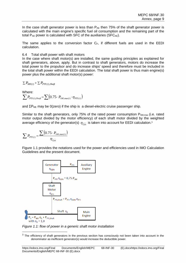
6.4 Total shaft power with shaft motors In the case where shaft motor(s) are installed, the same guiding principles as explained for shaft generators, above, apply. But in contrast to shaft generators, motors do increase the total power to the propulsor and do increase ships' speed and therefore must be included in the total shaft power within the EEDI calculation. The total shaft power is thus main engine(s) power plus the additional shaft motor(s) power:
ShaftiPTIiME PP ),()(
Where:
)()max(,),( 75.0 iPTIiSMShaftiPTI PP
and ΣPME may be 0(zero) if the ship is a diesel-electric cruise passenger ship. Similar to the shaft generators, only 75% of the rated power consumption PSM,max (i.e. rated motor output divided by the motor efficiency) of each shaft motor divided by the weighted
average efficiency of the generator(s) Gen
is taken into account for EEDI calculation.3
Gen
iSM
iPTI
PP
)max(,
)(
75.0
Figure 1.1 provides the notations used for the power and efficiencies used in IMO Calculation Guidelines and the present document.
Figure 1.1: flow of power in a generic shaft motor installation
3 The efficiency of shaft generators in the previous section has consciously not been taken into account in the
denominator as inefficient generator(s) would increase the deductible power.
MEPC 68/INF.30 Annex, page 10
https://edocs.imo.org/Final Documents/English/MEPC 68-INF-30 (E).docx
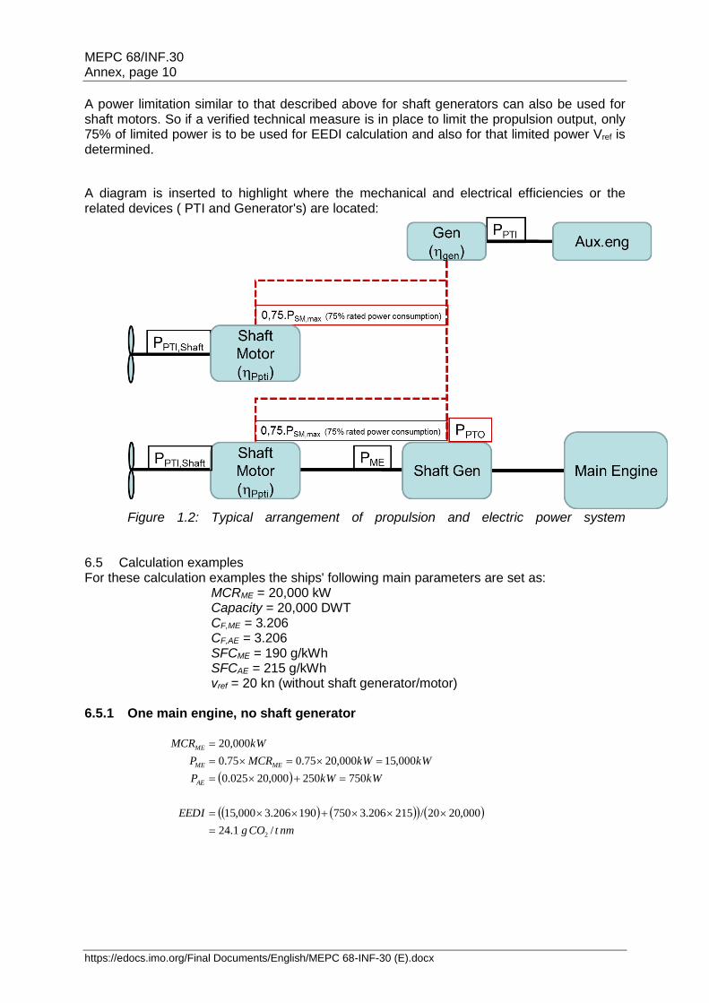
A power limitation similar to that described above for shaft generators can also be used for shaft motors. So if a verified technical measure is in place to limit the propulsion output, only 75% of limited power is to be used for EEDI calculation and also for that limited power Vref is determined.
A diagram is inserted to highlight where the mechanical and electrical efficiencies or the related devices ( PTI and Generator's) are located:
Figure 1.2: Typical arrangement of propulsion and electric power system
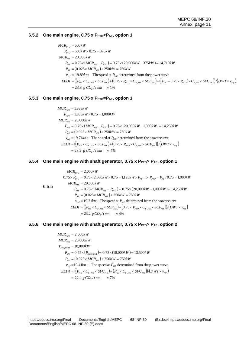
6.5 Calculation examples For these calculation examples the ships' following main parameters are set as:
MCRME = 20,000 kW Capacity = 20,000 DWT CF,ME = 3.206 CF,AE = 3.206 SFCME = 190 g/kWh SFCAE = 215 g/kWh vref = 20 kn (without shaft generator/motor)
6.5.1 One main engine, no shaft generator
nmtCOg
EEDI
kWkWP
kWkWMCRP
kWMCR
AE
MEME
ME
/1.24
000,2020/215206.3750190206.3000,15
750250000,20025.0
000,15000,2075.075.0
000,20
2
MEPC 68/INF.30 Annex, page 11
https://edocs.imo.org/Final Documents/English/MEPC 68-INF-30 (E).docxhttps://edocs.imo.org/Final Documents/English/MEPC 68-INF-30 (E).docx
6.5.2 One main engine, 0.75 x PPTO<PAE, option 1
%1/8.23
/75.075.0
curvepower thefrom determined at speed The:89.19
750250025.0
719,14375000,2075.075.0
000,20
37575.0500
500
2
,,,
nmtCOg
vDWTSFCCPPSCFCPSCFCPEEDI
Pknv
kWkWMCRP
kWkWkWPMCRP
kWMCR
kWkWP
kWMCR
refAEAEFPTOAEMEMEFPTOMEMEFME
MEref
MEAE
PTOMEME
ME
PTO
PTO
6.5.3 One main engine, 0.75 x PPTO=PAE, option 1
%4/2.23
/75.0
curvepower thefrom determined at speed The:71.19
750250025.0
250,14000,1000,2075.075.0
000,20
000,175.0333,1
333,1
2
,,
nmtCOg
vDWTSCFCPSCFCPEEDI
Pknv
kWkWMCRP
kWkWkWPMCRP
kWMCR
kWkWP
kWMCR
refMEMEFPTOMEMEFME
MEref
MEAE
PTOMEME
ME
PTO
PTO
6.5.4 One main engine with shaft generator, 0.75 x PPTO> PAE, option 1
6.5.5
%4/2.23
/75.0
curvepower thefrom determined at speed The :71.19
750250025.0
250,14000,1000,2075.075.0
000,20
000,175.0/125,175.0000,275.075.0
000,2
2
,,
nmtCOg
vDWTSCFCPSCFCPEEDI
Pknv
kWkWMCRP
kWkWkWPMCRP
kWMCR
kWPPPkWkWP
kWMCR
refMEMEFPTOMEMEFME
MEref
MEAE
PTOMEME
ME
AEPTOAEPTO
PTO
6.5.6 One main engine with shaft generator, 0.75 x PPTO> PAE, option 2
%7/4.22
/
curvepower thefrom determined at speed The :41.19
750250025.0
500,13000,1875.075.0
000,18
000,20
000,2
2
,,
nmtCOg
vDWTSFCCPSFCCPEEDI
Pknv
kWkWMCRP
kWkWPP
kWP
kWMCR
kWMCR
refMEMEFAEMEMEFME
MEref
MEAE
tShaft,limiME
tShaft,limi
ME
PTO
MEPC 68/INF.30 Annex, page 12
https://edocs.imo.org/Final Documents/English/MEPC 68-INF-30 (E).docx
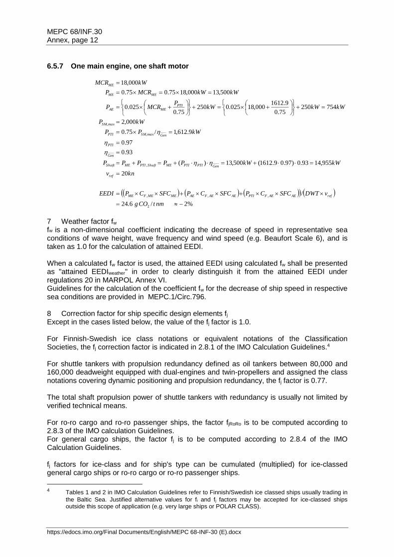
6.5.7 One main engine, one shaft motor
%2/6.24
/
20
955,1493.0)97.09.1612(500,13)(
93.0
97.0
9.612,1/75.0
000,2
75425075.0
9.1612000,18025.0250
75.0025.0
500,13000,1875.075.0
000,18
2
,,,
,
nmtCOg
vDWTSFCCPSFCCPSFCCPEEDI
knv
kWkWPPPPP
kWPP
kWP
kWkWkWP
MCRP
kWkWMCRP
kWMCR
refAEAEFPTIAEAEFAEMEMEFME
ref
GenPTIPTIMEShaftPTIMEShaft
Gen
PTI
GenSM,maxPTI
SM,max
PTIMEAE
MEME
ME
7 Weather factor fw fw is a non-dimensional coefficient indicating the decrease of speed in representative sea conditions of wave height, wave frequency and wind speed (e.g. Beaufort Scale 6), and is taken as 1.0 for the calculation of attained EEDI. When a calculated fw factor is used, the attained EEDI using calculated fw shall be presented as "attained EEDIweather" in order to clearly distinguish it from the attained EEDI under regulations 20 in MARPOL Annex VI. Guidelines for the calculation of the coefficient fw for the decrease of ship speed in respective sea conditions are provided in MEPC.1/Circ.796. 8 Correction factor for ship specific design elements fj Except in the cases listed below, the value of the fj factor is 1.0. For Finnish-Swedish ice class notations or equivalent notations of the Classification Societies, the fj correction factor is indicated in 2.8.1 of the IMO Calculation Guidelines.4 For shuttle tankers with propulsion redundancy defined as oil tankers between 80,000 and 160,000 deadweight equipped with dual-engines and twin-propellers and assigned the class notations covering dynamic positioning and propulsion redundancy, the fj factor is 0.77. The total shaft propulsion power of shuttle tankers with redundancy is usually not limited by verified technical means. For ro-ro cargo and ro-ro passenger ships, the factor fjRoRo is to be computed according to 2.8.3 of the IMO calculation Guidelines. For general cargo ships, the factor fj is to be computed according to 2.8.4 of the IMO Calculation Guidelines. fj factors for ice-class and for ship's type can be cumulated (multiplied) for ice-classed general cargo ships or ro-ro cargo or ro-ro passenger ships.
4 Tables 1 and 2 in IMO Calculation Guidelines refer to Finnish/Swedish ice classed ships usually trading in
the Baltic Sea. Justified alternative values for fi and fj factors may be accepted for ice-classed ships outside this scope of application (e.g. very large ships or POLAR CLASS).
MEPC 68/INF.30 Annex, page 13
https://edocs.imo.org/Final Documents/English/MEPC 68-INF-30 (E).docxhttps://edocs.imo.org/Final Documents/English/MEPC 68-INF-30 (E).docx
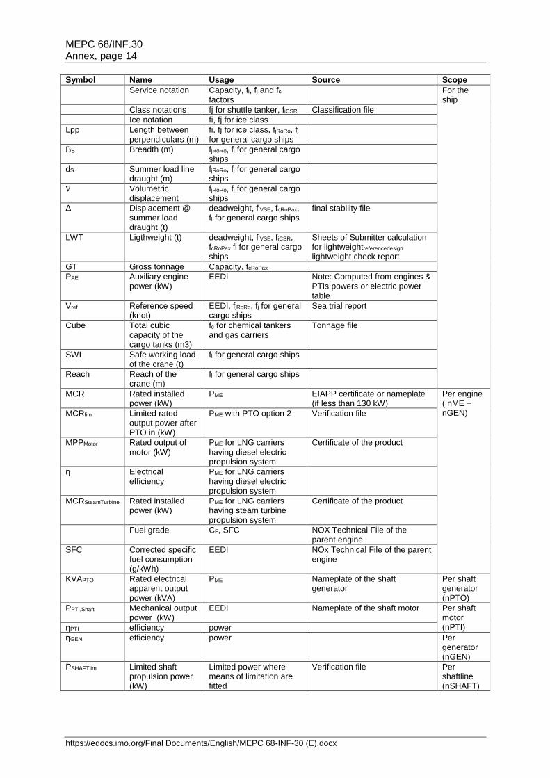
9 Capacity factor fi Except in the cases listed below, the value of the fi factor is 1.0. For Finnish-Swedish ice class notations or equivalent notations of the Classification Societies, the fi correction factor is indicated in 2.11.1 of the IMO Calculation Guidelines.4 For a ship with voluntary structural enhancement, the fiVSE factor is to be computed according to 2.11.2 of the IMO Calculation Guidelines. For bulk carriers and oil tankers built in accordance with the Common Structural Rules and assigned the class notation CSR, the fiCSR factor is to be computed according to 2.11.3 of the IMO Calculation Guidelines. fi capacity factors can be cumulated (multiplied), but the reference design for calculation of fiVSE is to comply with the ice notation and/or Common Structural Rules as the case may be. 10 Cubic capacity correction factor fc AND cargo gears FACTOR fl Except in the cases listed below, the value of the fc and fl factors is 1.0. For chemical tankers as defined in regulation 1.16.1 of MARPOL Annex II, the fc factor is to be computed according to 2.12.1 of the IMO Calculation Guidelines. For gas carriers having direct diesel driven propulsion constructed or adapted and used for the carriage in bulk of liquefied natural gas, the fc factor is to be computed according to 2.12.2 of the IMO Calculation Guidelines. This factor is not to be applied to LNG carriers defined in regulation 2.38 of MARPOL Annex VI. For ro-ro passenger ships having a DWT/GT-ratio of less than 0.25, the cubic capacity correction factor fcRoPax is to be computed according to 2.12.3 of the IMO Calculation Guidelines. For general cargo ships only equipped with cranes, side loaders or ror-ro ramps, the fl correction factor is to be computed according to 2.14 of the IMO Calculation Guidelines. 11 Innovative energy efficient technologies Innovative energy efficient technologies are to be taken into account according to the 2013 Guidance on treatment of innovative energy efficiency technologies for calculation and verification of the attained EEDI, MEPC.1/Circ.815 12 Example of calculation 12.1 List of input parameters for calculation of EEDI The input parameters used in the calculation of the EEDI are provided in Table 1. The values of all these parameters are to be indicated in the EEDI Technical File and the documents listed in the "source" column are to be submitted to the verifier. For electrical generator, the rated electrical output in kW is related to the rated apparent power output in kVA by the following relation: MCRPTO (kW) = KVAPTO * 0.8 where 0.8 is the conventional power factor. Table 1: input parameters for calculation of EEDI
MEPC 68/INF.30 Annex, page 14
https://edocs.imo.org/Final Documents/English/MEPC 68-INF-30 (E).docx
Symbol Name Usage Source Scope
Service notation Capacity, fi, fj and fc factors
For the ship
Class notations fj for shuttle tanker, fiCSR Classification file
Ice notation fi, fj for ice class
Lpp Length between perpendiculars (m)
fi, fj for ice class, fjRoRo, fj for general cargo ships
BS Breadth (m) fjRoRo, fj for general cargo ships
dS Summer load line draught (m)
fjRoRo, fj for general cargo ships
∇ Volumetric displacement
fjRoRo, fj for general cargo ships
Δ Displacement @ summer load draught (t)
deadweight, fiVSE, fcRoPax, fl for general cargo ships
final stability file
LWT Ligthweight (t) deadweight, fiVSE, fiCSR, fcRoPax fl for general cargo ships
Sheets of Submitter calculation for lightweightreferencedesign lightweight check report
GT Gross tonnage Capacity, fcRoPax
PAE Auxiliary engine power (kW)
EEDI Note: Computed from engines & PTIs powers or electric power table
Vref Reference speed (knot)
EEDI, fjRoRo, fj for general cargo ships
Sea trial report
Cube Total cubic capacity of the cargo tanks (m3)
fc for chemical tankers and gas carriers
Tonnage file
SWL Safe working load of the crane (t)
fl for general cargo ships
Reach Reach of the crane (m)
fl for general cargo ships
MCR Rated installed power (kW)
PME EIAPP certificate or nameplate (if less than 130 kW)
Per engine ( nME + nGEN) MCRlim Limited rated
output power after PTO in (kW)
PME with PTO option 2 Verification file
MPPMotor Rated output of motor (kW)
PME for LNG carriers having diesel electric propulsion system
Certificate of the product
η Electrical efficiency
PME for LNG carriers having diesel electric propulsion system
MCRSteamTurbine Rated installed power (kW)
PME for LNG carriers having steam turbine propulsion system
Certificate of the product
Fuel grade CF, SFC NOX Technical File of the parent engine
SFC Corrected specific fuel consumption (g/kWh)
EEDI NOx Technical File of the parent engine
KVAPTO Rated electrical apparent output power (kVA)
PME Nameplate of the shaft generator
Per shaft generator (nPTO)
PPTI,Shaft Mechanical output power (kW)
EEDI Nameplate of the shaft motor Per shaft motor (nPTI) ηPTI efficiency power
ηGEN efficiency power Per generator (nGEN)
PSHAFTlim Limited shaft propulsion power (kW)
Limited power where means of limitation are fitted
Verification file Per shaftline (nSHAFT)

MEPC 68/INF.30 Annex, page 15
https://edocs.imo.org/Final Documents/English/MEPC 68-INF-30 (E).docxhttps://edocs.imo.org/Final Documents/English/MEPC 68-INF-30 (E).docx
12.2 Sample calculation of EEDI A sample of document to be submitted to the verifier is provided in Appendix 2. In addition, Appendix 6 contains a list of sample calculations of EEDI, as follows:
Appendix 6.1: Cruise passenger ship with diesel-electric propulsion
Appendix 6.2: LNG carrier with diesel-electric propulsion
Appendix 6.3: Diesel-driven LNG carrier with re-liquefaction system
Appendix 6.4: LNG carrier with steam turbine propulsion
MEPC 68/INF.30 Annex, page 16
https://edocs.imo.org/Final Documents/English/MEPC 68-INF-30 (E).docx
Part III – Verification of EEDI
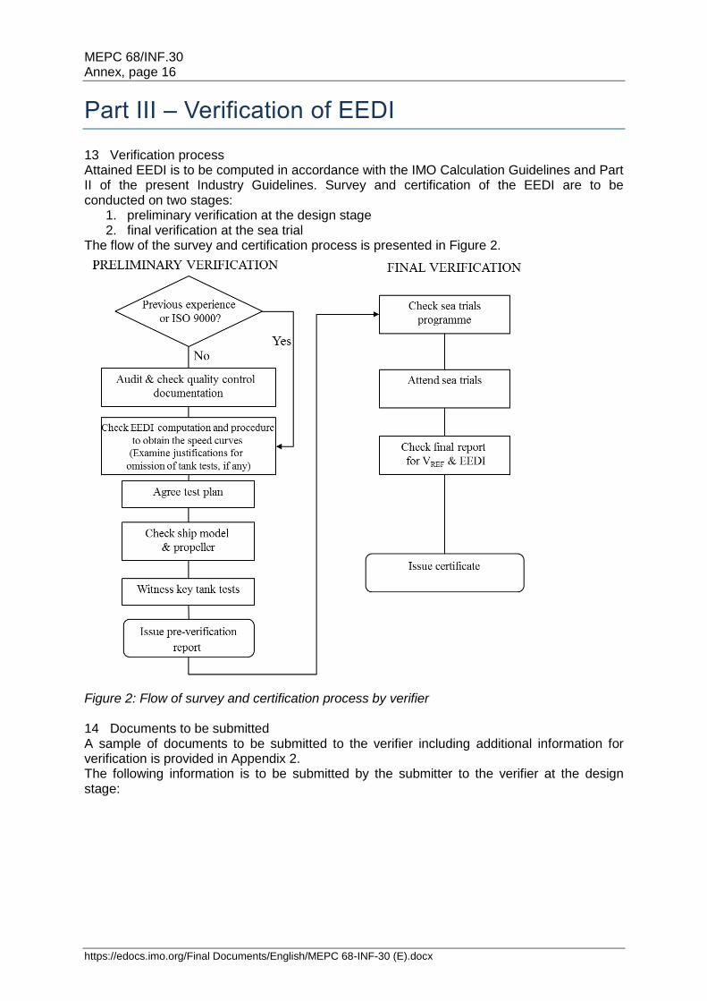
13 Verification process Attained EEDI is to be computed in accordance with the IMO Calculation Guidelines and Part II of the present Industry Guidelines. Survey and certification of the EEDI are to be conducted on two stages:
1. preliminary verification at the design stage 2. final verification at the sea trial
The flow of the survey and certification process is presented in Figure 2.
Figure 2: Flow of survey and certification process by verifier 14 Documents to be submitted A sample of documents to be submitted to the verifier including additional information for verification is provided in Appendix 2. The following information is to be submitted by the submitter to the verifier at the design stage:

MEPC 68/INF.30 Annex, page 17
https://edocs.imo.org/Final Documents/English/MEPC 68-INF-30 (E).docxhttps://edocs.imo.org/Final Documents/English/MEPC 68-INF-30 (E).docx
EEDI Technical File EEDI Technical File as defined in the IMO Verification Guidelines. See example of the EEDI Technical File in Appendix 1 of IMO Verification Guidelines.
NOx Technical File Copy of the NOx Technical File and documented summary of the SFC correction for each type of main and auxiliary engine with copy of EIAPP certificate. Note: if the NOx Technical File has not been approved at the time of the preliminary verification, the SFC value with the addition of the guarantee tolerance is to be provided by Manufacturer. In this case, the NOx Technical File is to be submitted at the final verification stage.
Electric Power Table If PAE is significantly different from the values computed using the formula in 2.5.6.1 or 2.5.6.2 of the IMO Calculation Guidelines
Ship lines and model particulars - Lines of ship - Report including the particulars of the ship model and propeller model
Verification file of power limitation technical arrangement
If the propulsion power is voluntarily limited by verified technical means
Power curves Power-speed curves predicted at full scale in sea trial condition and EEDI condition
Description of the towing tank test facility and towing tank test organization quality manual
If the verifier has no recent experience with the towing tank test facility and the towing tank test organization quality system is not ISO 9001 certified. - Quality management system of the towing tank test including process control, justifications concerning repeatability and quality management processes - Records of measuring equipment calibration as described in Appendix 3 - Standard model-ship extrapolation and correlation method (applied method and tests description)
Gas fuel oil general arrangement plan
If gas fuel is used as the primary fuel of the ship fitted with dual fuel engines. Gas fuel storage tanks (with capacities) and bunkering facilities are to be described.
Towing Tank Tests Plan Plan explaining the different steps of the towing tank tests and the scheduled inspections allowing the verifier to check compliance with the items listed in Appendix 1 concerning tank tests
Towing Tank Tests Report - Report of the results of the towing tank tests at sea trial and EEDI condition as required in Appendix 4 - Values of the experience-based parameters defined in the standard model-ship correlation method used by the towing tank test organization/shipyard - Reasons for exempting a towing tank test, only if applicable - Numerical calculations report and validation file of these calculations, only if calculations are used to derive power curves
Ship reference speed Vref Detailed calculation process of the ship speed, which is to include the estimation basis of experience-based parameters such as roughness coefficient, wake scaling coefficient
Table 2: documents to be submitted at the design stage The following information is to be submitted by the submitter to the verifier at the final verification stage (and before the sea trials for the programme of sea trials): Programme of sea trials Description of the test procedure to be used for the speed trial, with number
of speed points to be measured and indication of PTO/PTI to be in operation, if any.
Sea trials report Report of sea trials with detailed computation of the corrections allowing determination of the reference speed Vref
Final stability file Final stability file including lightweight of the ship and displacement table based on the results of the inclining test or the lightweight check
Final power curves Final power curve in the EEDI condition showing the speed adjustment methodology
Revised EEDI Technical File Including identification of the parameters differing from the calculation performed at the initial verification stage
Ship lines Lines of actual ship
Table 3: documents to be submitted at the final verification stage
MEPC 68/INF.30 Annex, page 18
https://edocs.imo.org/Final Documents/English/MEPC 68-INF-30 (E).docx
In line with the IMO Verification Guidelines (4.1.2), it is recognized that the documents listed above may contain confidential information of submitters, which requires Intellectual Property Rights (IPR) protection. In the case where the submitter wants a non-disclosure agreement with the verifier, the additional information is to be provided to the verifier upon mutually agreed terms and conditions. 15 Preliminary verification at the design stage 15.1 Scope of the verifier work For the preliminary verification of the EEDI at the design stage, the verifier:
Review the EEDI Technical File, check that all the input parameters (see 12.1 above) are documented and justified and check that the possible omission of a towing tank test has been properly justified
Check that the ITTC procedures and quality system are implemented by the organization conducting the towing tank tests. The verifier should possibly audit the quality management system of the towing tank if previous experience is insufficiently demonstrated
Witness the towing tank tests according to a test plan initially agreed between the submitter and the verifier
Check that the work done by the towing tank test organization is consistent with the present Guidelines. In particular, the verifier will check that the power curves at full scale are determined in a consistent way between sea trials and EEDI loading conditions, applying the same calculation process of the power curves and considering justifiable differences of experience based parameters between the two conditions
Issue a pre-verification report
15.2 Definitions Experience-based parameters means parameters used in the determination of the scale effects coefficients of correlation between the towing tank model scale results and the full scale predictions of power curves. This may include:
1. Hull roughness correction 2. Wake correction factor 3. Air resistance correction factor (due to superstructures and deck load) 4. Appendages correction factor (for appendages not present at model scale) 5. Propeller cavitation correction factor 6. Propeller open-water characteristics correction 7. CP and CN (see below) 8. ∆CFC and ∆wC (see below)
Ship of the same type means a ship of which hull form (expressed in the lines such as sheer plan and body plan) excluding additional hull features such as fins and of which principal particulars are identical to that of the base ship. Definition of survey methods directly involving the verifier: Review and Witness. Review means the act of examining documents in order to determine identification and traceability and to confirm that requested information are present and that EEDI calculation process conforms to relevant requirements. Witness means the attendance at scheduled key steps of the towing tank tests in accordance with the agreed Test Plan to the extent necessary to check compliance with the survey and certification requirements.

MEPC 68/INF.30 Annex, page 19
https://edocs.imo.org/Final Documents/English/MEPC 68-INF-30 (E).docxhttps://edocs.imo.org/Final Documents/English/MEPC 68-INF-30 (E).docx
15.3 Towing tank tests and numerical calculations There are two loading conditions to be taken into account for EEDI: EEDI loading condition and sea trial condition. The speed power curves for these two loading conditions are to be based on towing tank test measurements. Towing tank test means model towing tests, model self-propulsion tests and model propeller open water tests. Numerical calculations may be accepted as equivalent to model propeller open water tests. A towing tank test for an individual ship may be omitted based on technical justifications such as availability of the results of towing tank tests for ships of the same type according to 4.2.5 of the IMO Verification Guidelines. Numerical calculations may be submitted to justify derivation of speed power curves, where only one parent hull form have been verified with towing tank tests, in order to evaluate the effect of additional hull features such as fore bulb variations, fins and hydrodynamic energy saving devices. These numerical tests may include CFD calculation of propulsive efficiency at reference speed Vref as well as hull resistance variations and propeller open water efficiency. In order to be accepted, these numerical tests are to be carried out in accordance with defined quality and technical standards (ITTC 7.5-03-01-04 at its latest revision or equivalent). The comparison of the CFD-computed values of the unmodified parent hull form with the results of the towing tank tests must be submitted for review. 15.4 Qualification of verifier personnel Surveyors of the verifier are to confirm through review and witness as defined in 15.2 that the calculation of EEDI is performed according to the relevant requirements listed in 1.1. The surveyors are to be qualified to be able to carry out these tasks and procedures are to be in place to ensure that their activities are monitored. 15.5 Review of the towing tank test organization quality system The verifier is to familiarize with the towing tank test organization test facilities, measuring equipment, standard model-ship extrapolation and correlation method (applied method and tests description) and quality system for consideration of complying with the requirements of 15.6 prior to the test attendance when the verifier has no recent experience of the towing tank test facilities. When in addition the towing tank test organization quality control system is not certified according to a recognized scheme (ISO 9001 or equivalent) the following additional information relative to the towing tank test organization is to be submitted to the verifier:
1. descriptions of the towing tank test facility; this includes the name of the facility, the particulars of towing tanks and towing equipment, and the records of calibration of each monitoring equipment as described in Appendix 3
2. quality manual containing at least the information listed in the ITTC Sample quality manual (2002 issue) Records of measuring equipment calibration as described in Appendix 3
15.6 Review and Witness The verifier is to review the EEDI Technical File, using also the other documents listed in table 2 and submitted for information in order to verify the calculation of EEDI at design stage. This review activity is described in Appendix 1. Since detailed process of the towing tank tests depends on the practice of each submitter, sufficient information is to be included in the document submitted to the verifier to show that the principal scheme of the towing tank test process meets the requirements of the reference documents listed in Appendix 1 and Appendix 4.
MEPC 68/INF.30 Annex, page 20
https://edocs.imo.org/Final Documents/English/MEPC 68-INF-30 (E).docx
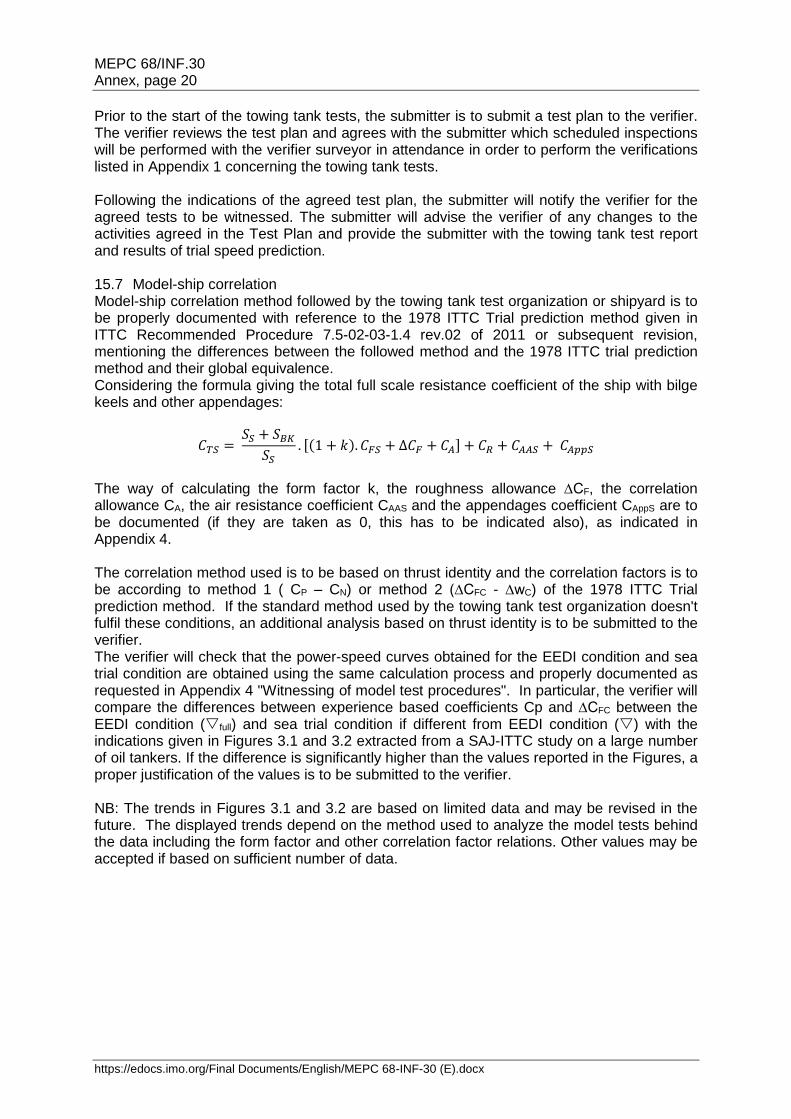
Prior to the start of the towing tank tests, the submitter is to submit a test plan to the verifier. The verifier reviews the test plan and agrees with the submitter which scheduled inspections will be performed with the verifier surveyor in attendance in order to perform the verifications listed in Appendix 1 concerning the towing tank tests. Following the indications of the agreed test plan, the submitter will notify the verifier for the agreed tests to be witnessed. The submitter will advise the verifier of any changes to the activities agreed in the Test Plan and provide the submitter with the towing tank test report and results of trial speed prediction. 15.7 Model-ship correlation Model-ship correlation method followed by the towing tank test organization or shipyard is to be properly documented with reference to the 1978 ITTC Trial prediction method given in ITTC Recommended Procedure 7.5-02-03-1.4 rev.02 of 2011 or subsequent revision, mentioning the differences between the followed method and the 1978 ITTC trial prediction method and their global equivalence. Considering the formula giving the total full scale resistance coefficient of the ship with bilge keels and other appendages:
𝐶𝑇𝑆 = 𝑆𝑆 + 𝑆𝐵𝐾
𝑆𝑆. [(1 + 𝑘). 𝐶𝐹𝑆 + ∆𝐶𝐹 + 𝐶𝐴] + 𝐶𝑅 + 𝐶𝐴𝐴𝑆 + 𝐶𝐴𝑝𝑝𝑆
The way of calculating the form factor k, the roughness allowance ∆CF, the correlation allowance CA, the air resistance coefficient CAAS and the appendages coefficient CAppS are to be documented (if they are taken as 0, this has to be indicated also), as indicated in Appendix 4. The correlation method used is to be based on thrust identity and the correlation factors is to be according to method 1 ( CP – CN) or method 2 (∆CFC - ∆wC) of the 1978 ITTC Trial prediction method. If the standard method used by the towing tank test organization doesn't fulfil these conditions, an additional analysis based on thrust identity is to be submitted to the verifier. The verifier will check that the power-speed curves obtained for the EEDI condition and sea trial condition are obtained using the same calculation process and properly documented as requested in Appendix 4 "Witnessing of model test procedures". In particular, the verifier will compare the differences between experience based coefficients Cp and ∆CFC between the EEDI condition (full) and sea trial condition if different from EEDI condition () with the indications given in Figures 3.1 and 3.2 extracted from a SAJ-ITTC study on a large number of oil tankers. If the difference is significantly higher than the values reported in the Figures, a proper justification of the values is to be submitted to the verifier. NB: The trends in Figures 3.1 and 3.2 are based on limited data and may be revised in the future. The displayed trends depend on the method used to analyze the model tests behind the data including the form factor and other correlation factor relations. Other values may be accepted if based on sufficient number of data.
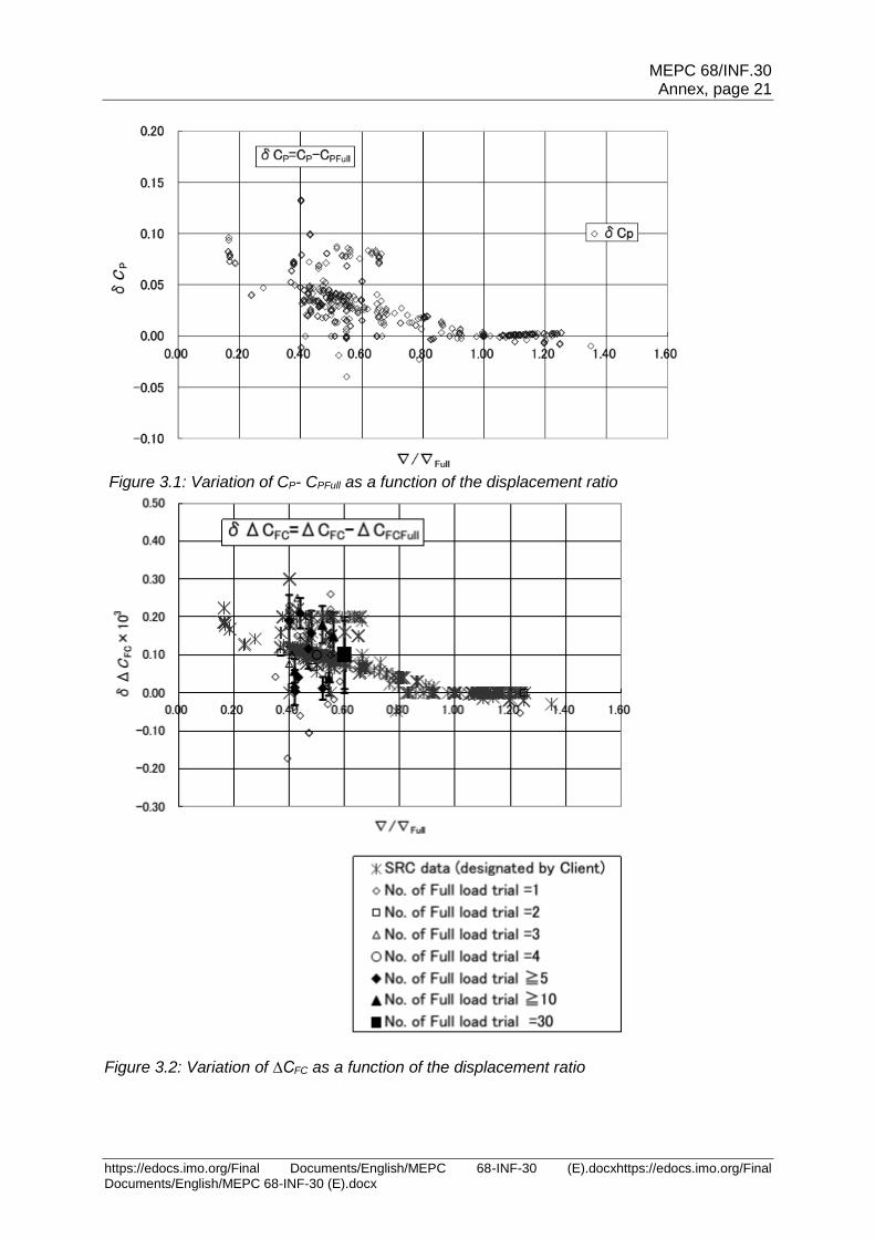
MEPC 68/INF.30 Annex, page 21
https://edocs.imo.org/Final Documents/English/MEPC 68-INF-30 (E).docxhttps://edocs.imo.org/Final Documents/English/MEPC 68-INF-30 (E).docx
Figure 3.1: Variation of CP- CPFull as a function of the displacement ratio
Figure 3.2: Variation of ∆CFC as a function of the displacement ratio
MEPC 68/INF.30 Annex, page 22
https://edocs.imo.org/Final Documents/English/MEPC 68-INF-30 (E).docx
15.8 Pre-verification report The verifier issues the report on the "Preliminary Verification of EEDI" after it has verified the attained EEDI at the design stage in accordance with paragraphs 4.1 and 4.2 of the IMO Verification Guidelines. A sample of the report on the "Preliminary Verification of EEDI" is provided in Appendix 5. 16 Final verification at sea trial 16.1 Sea trial procedure For the verification of the EEDI at sea trial stage, the verifier shall:
Examine the programme of the sea trial to check that the test procedure and in particular that the number of speed measurement points comply with the requirements of the IMO Verification Guidelines (see note below).
Perform a survey to ascertain the machinery characteristics of some important electric load consumers and producers included in the EPT, if the power PAE is directly computed from the EPT data's.
Attend the sea trial and notes the main parameters to be used for the final calculation of the EEDI, as given under 4.3.3 of the IMO Verification Guidelines
Review the sea trial report provided by the submitter and check that the measured power and speed have been corrected accordingly (see note below)
Check that the power curve estimated for EEDI condition further to sea trial is obtained by power adjustment.
Review the revised EEDI Technical File.
Issue or endorse the International Energy Efficiency Certificate
Note: For application of the present Guidelines, Sea conditions and ship speed should be measured in accordance with ITTC Recommended Procedure 7.5-04-01-01.1 Speed and Power Trials Part 1; 2014 or ISO 15016:2015
Table 5 lists the data which are to be measured and recorded during sea trials: Symbol Name Measurement Remark
Time and duration of sea trial
Draft marks readings
Air and sea temperature
Main engine setting Machinery log
Ψ0 Course direction (rad) Compass
VG Speed over ground (m/s) GPS
n Propeller rpm (rpm) Tachometer
PS Power measured (kW) Torsion meter or strain gauges (for torque measurement) or any alternative method that offer an equivalent level of precision and accuracy of power measurement
VWR Relative wind velocity (m/s) Wind indicator
ΨWR Relative wind direction (rad) See above
Tm Mean wave period (seas and swell) (s)
Visual observation by multiple observers supplemented by hindcast data or wave measuring devices (wave buoy, wave radar, etc.)
H1/3 Significant wave height (seas and swell) (m)
See above
χ Incident angle of waves ( seas and swell) (rad)
See above
δR Rudder angle (rad) Rudder
β Drift angle (rad) GPS
Table 5: Measured data during sea trials Prior to the sea trial, the programme of the sea trials and , if available, additional documents listed in table 3 are to be submitted to the verifier in order for the verifier to check the
MEPC 68/INF.30 Annex, page 23
https://edocs.imo.org/Final Documents/English/MEPC 68-INF-30 (E).docxhttps://edocs.imo.org/Final Documents/English/MEPC 68-INF-30 (E).docx
procedure and to attend the sea trial and perform the verifications included in Appendix 1 concerning the sea trial. The ship speed is to be measured at sea trial for at least three power settings of which range includes the total propulsion power defined in 5.2 according to the requirements of the IMO Verification Guidelines 4.3.6. This requirement applies individually to each ship, even if the ship is a sistership of a parent vessel. If it is physically impossible to meet the conditions in the ISO15016:2015 or ITTC Recommended Procedure 7.5-04-01-01, a practical treatment shall be allowed based on the documented mutual agreement among the owner, the verifier and the shipbuilder. 16.2 Estimation of the EEDI reference speed VRef The adjustment procedure is applicable to the most complex case where sea trials cannot be conducted in EEDI loading condition. It is expected that this will be usually the case for cargo ships like bulk carriers for instance. Ship speed should be measured in accordance with ISO 15016:2015 or ITTC Recommended Procedure 7.5-04-01-01.1, including the accuracy objectives under paragraph 1 of ITTC Recommended Procedure 7.5-04-01-01.2. In particular, if the shaft torque measurement device cannot be installed near the output flange of main engine, then the efficiency from the measured shaft power to brake horse power should be taken into account. Using the speed-power curve obtained from the sea trials in the trial condition, the conversion of ship's speed from the trial condition to the EEDI condition shall be carried out by power adjustment as defined in Annex I of ISO 15016:2015. The reference speed Vref should be determined based on sea trials which have been carried out and evaluated in accordance with ISO 15016:2015 or equivalent (see note in 16.1) Reference is made to paragraph 3 of Appendix 2 (Figure 3.1) where an example is provided.
16.3 Revision of EEDI Technical File The EEDI Technical File is to be revised, as necessary, by taking into account the results of sea trials. Such revision is to include, as applicable, the adjusted power curve based on the results of sea trial (namely, modified ship speed under the condition as specified in paragraph 2.2 of the IMO Calculation Guidelines), the finally determined deadweight/gross tonnage and the recalculated attained EEDI and required EEDI based on these modifications. The revised EEDI Technical File is to be submitted to the verifier for the confirmation that the revised attained EEDI is calculated in accordance with regulation 20 of MARPOL Annex VI and the IMO Calculation Guidelines
MEPC 68/INF.30 Annex, page 24
https://edocs.imo.org/Final Documents/English/MEPC 68-INF-30 (E).docx
17 Verification of the EEDI in case of major conversion In this section, a major conversion is defined as in MARPOL Annex VI regulation 2.24 and interpretations in MEPC.1/Circ.795/Rev2, subject to the approval of the Administration. For verification of the attained EEDI after a major conversion, no speed trials are necessary if the conversion or modifications don't involve a variation in reference speed. In case of conversion, the verifier will review the modified EEDI Technical File. If the review leads to the conclusion that the modifications couldn't cause the ship to exceed the applicable required EEDI, the verifier will not request speed trials. If such conclusion cannot be reached, like in the case of a lengthening of the ship, or increase of propulsion power of 10% or more, speed trials will be required. If an Owner voluntarily requests re-certification of EEDI with IEE Certificate reissuance on the basis of an improvement to the ship efficiency, the verifier may request speed trials in order to validate the attained EEDI value improvement. If speed trials are performed after conversion or modifications changing the attained EEDI value, tank tests verification is to be requested if the speed trials conditions differ from the EEDI condition. In this case, numerical calculations performed in accordance with defined quality and technical standards (ITTC 7.5-03-01-04 at its latest revision or equivalent) replacing tank tests may be accepted by the verifier to quantify influence of the hull modifications. In case of major conversion of a ship without prior EEDI, EEDI computation is not required, except if the Administration considers that due to the extensive character of the conversion, the ship is to be considered as a new one.
MEPC 68/INF.30 Annex, page 25
https://edocs.imo.org/Final Documents/English/MEPC 68-INF-30 (E).docxhttps://edocs.imo.org/Final Documents/English/MEPC 68-INF-30 (E).docx
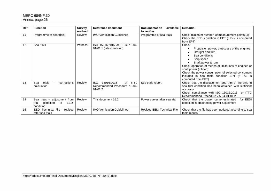
APPENDIX 1 Review and witness points
Table 4: Review and witness points Ref. Function Survey
method Reference document Documentation available
to verifier Remarks
01 EEDI Technical File Review IMO Verification Guidelines This document
Documents in table 2
02 Limitation of power Review IMO Calculation Guidelines Verification file of limitation technical means
Only If means of limitation are fitted
03 Electric Power Table Review Appendix 2 to IMO Calculation Guidelines Appendix 2 to IMO Verification Guidelines
EPT EPT-EEDI form
Only if PAE is significantly different from the values computed using the formula in 2.5.6.1 to 2.5.6.3 of the IMO Calculation Guidelines
04 Calibration of towing tank test measuring equipment
Review & witness
Appendix 3 Calibration reports Check at random that measuring devices are well identified and that calibration reports are currently valid
05 Model tests – ship model Review & witness
Appendix 4 Ship lines plan & offsets table Ship model report
Checks described in Appendix 4.1
06 Model tests – propeller model Review & witness
Appendix 4 Propeller model report Checks described in Appendix 4.2
07 Model tests – Resistance test, Propulsion test, Propeller open water test
Review & witness
Appendix 4 Towing tank tests report Checks described in Appendix 4.3 Note: propeller open water test is not needed if a stock propeller is used. In this case, the open water characteristics of the stock propeller are to be annexed to the towing tank tests report.
08 Model-ship extrapolation and correlation
Review ITTC 7.5-02-03-01.4 1978 ITTC performance prediction method (rev.02 of 2011 or subsequent revision) Appendix 4 This document 15.7
Documents in table 2 Check that the ship-model correlation is based on thrust identity with correlation factor according to method 1 ( CP – CN) or method 2 (∆CFC - ∆wC) Check that the power-speed curves obtained for the EEDI condition and sea trial condition are obtained using the same calculation process with justified values of experience-based parameters
09 Numerical calculations replacing towing tank tests
Review ITTC 7.5-03-01-04 (latest revision) or equivalent
Report of calculations For justification of calculations replacing model tests refer to 15.3.
10 Electrical machinery survey prior to sea trials
Witness Appendix 2 to IMO Verification Guidelines
Only if PAE is computed from EPT
MEPC 68/INF.30 Annex, page 26
https://edocs.imo.org/Final Documents/English/MEPC 68-INF-30 (E).docx
Ref. Function Survey method
Reference document Documentation available to verifier
Remarks
11 Programme of sea trials Review IMO Verification Guidelines
Programme of sea trials Check minimum number of measurement points (3) Check the EEDI condition in EPT (if PAE is computed from EPT)
12 Sea trials Witness ISO 15016:2015 or ITTC 7.5-04-01-01.1 (latest revision)
Check:
Propulsion power, particulars of the engines
Draught and trim
Sea conditions
Ship speed
Shaft power & rpm Check operation of means of limitations of engines or shaft power (if fitted) Check the power consumption of selected consumers included in sea trials condition EPT (if PAE is computed from EPT)
13 Sea trials – corrections calculation
Review ISO 15016:2015 or ITTC Recommended Procedure 7.5-04-01-01.2
Sea trials report Check that the displacement and trim of the ship in sea trial condition has been obtained with sufficient accuracy Check compliance with ISO 15016:2015 or ITTC Recommended Procedure 7.5-04-01-01.2
14 Sea trials – adjustment from trial condition to EEDI condition
Review This document 16.2 Power curves after sea trial Check that the power curve estimated for EEDI condition is obtained by power adjustment
15 EEDI Technical File – revised after sea trials
Review IMO Verification Guidelines Revised EEDI Technical File Check that the file has been updated according to sea trials results
MEPC 68/INF.30 Annex, page 27
https://edocs.imo.org/Final Documents/English/MEPC 68-INF-30 (E).docx
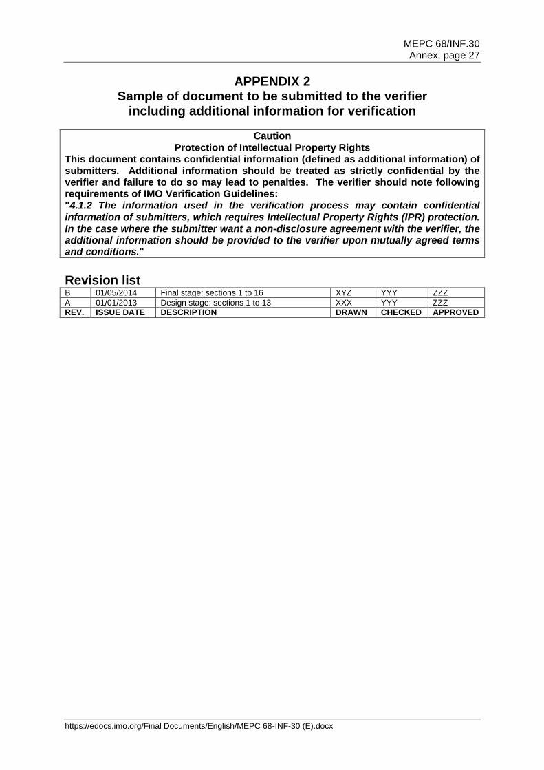
APPENDIX 2 Sample of document to be submitted to the verifier
including additional information for verification
Caution Protection of Intellectual Property Rights
This document contains confidential information (defined as additional information) of submitters. Additional information should be treated as strictly confidential by the verifier and failure to do so may lead to penalties. The verifier should note following requirements of IMO Verification Guidelines: "4.1.2 The information used in the verification process may contain confidential information of submitters, which requires Intellectual Property Rights (IPR) protection. In the case where the submitter want a non-disclosure agreement with the verifier, the additional information should be provided to the verifier upon mutually agreed terms and conditions." Revision list B 01/05/2014 Final stage: sections 1 to 16 XYZ YYY ZZZ
A 01/01/2013 Design stage: sections 1 to 13 XXX YYY ZZZ
REV. ISSUE DATE DESCRIPTION DRAWN CHECKED APPROVED
MEPC 68/INF.30 Annex, page 28
https://edocs.imo.org/Final Documents/English/MEPC 68-INF-30 (E).docx
1 General This calculation of the Energy Efficiency Design Index (EEDI) is based on:
Resolution MEPC.203(62) and MEPC.251(66) amendments to include regulations on energy efficiency in MARPOL Annex VI
Resolution MEPC.245(66) 2014 Guidelines on the method of calculation of the attained Energy Efficiency Design Index (EEDI) for new ships
Calculations are being dealt with according to the Industry Guidelines on calculation and verification of EEDI, 2015 issue.
2 Data
2.1 Main parameters Parameter Value Reference
Owner OWNER
Builder YARD
Hull No. 12346
IMO No. 94111XX
Ship's type Bulk carrier
Ship classification notations I HULL, MACH, Bulk Carrier CSR BC-A (holds 2 and 4 may be empty) ESP GRAB[20] Unrestricted Navigation AUT-UMS, GREEN PASSPORT, INWATERSURVEY, MON-SHAFT
HULL PARTICULARS
Length overall 191.0 m
Length between perpendiculars 185.0 m
Breadth, moulded 32.25 m
Depth, moulded 17.9 m
Summer load line draught, moulded 12.70 m
Deadweight at summer load line draught 55 000 DWT
Lightweight 11 590 tons
Owner's voluntary structural enhancements No
MAIN ENGINE
Type & manufacturer BUILDER 6SRT60ME
Specified Maximum Continuous Rating (SMCR) 9 200 kW x 105 rpm
SFC at 75% SMCR 171 g/kWh See paragraph 10.1
Number of set 1
Fuel type Diesel/Gas oil
AUXILIARY ENGINES
Type & manufacturer BUILDER 5X28
Specified Maximum Continuous Rating (SMCR) 650 kW x 700 rpm
SFC at 50% SMCR 205 g/kWh See paragraph 10.2
Number of set 3
Fuel type Diesel/Gas oil
OVERVIEW OF PROPULSION SYSTEM AND ELECTRICITY SUPPLY SYSTEM
See section 4
SHAFT GENERATORS
Type & manufacturer None
Rated electrical output power
MEPC 68/INF.30 Annex, page 29
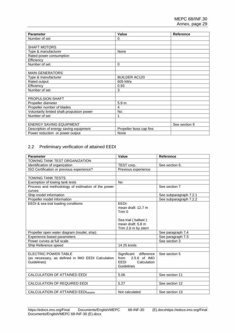
https://edocs.imo.org/Final Documents/English/MEPC 68-INF-30 (E).docxhttps://edocs.imo.org/Final Documents/English/MEPC 68-INF-30 (E).docx
Parameter Value Reference
Number of set 0
SHAFT MOTORS
Type & manufacturer None
Rated power consumption
Efficiency
Number of set 0
MAIN GENERATORS
Type & manufacturer BUILDER AC120
Rated output 605 kWe
Efficiency 0.93
Number of set 3
PROPULSION SHAFT
Propeller diameter 5.9 m
Propeller number of blades 4
Voluntarily limited shaft propulsion power No
Number of set 1
ENERGY SAVING EQUIPMENT See section 9
Description of energy saving equipment Propeller boss cap fins
Power reduction or power output None
2.2 Preliminary verification of attained EEDI Parameter Value Reference
TOWING TANK TEST ORGANIZATION
Identification of organization TEST corp. See section 6.
ISO Certification or previous experience? Previous experience
TOWING TANK TESTS
Exemption of towing tank tests No
Process and methodology of estimation of the power curves
See section 7
Ship model information See subparagraph 7.2.1
Propeller model information See subparagraph 7.2.2
EEDI & sea trial loading conditions EEDI: mean draft: 12.7 m Trim 0 Sea trial ( ballast ): mean draft: 5.8 m Trim 2.6 m by stern
Propeller open water diagram (model, ship) See paragraph 7.4
Experience based parameters See paragraph 7.3
Power curves at full scale See section 3
Ship Reference speed 14.25 knots
ELECTRIC POWER TABLE (as necessary, as defined in IMO EEDI Calculation Guidelines)
Significant difference from 2.5.6 of IMO EEDI Calculation Guidelines
See section 5
CALCULATION OF ATTAINED EEDI 5.06 See section 11
CALCULATION OF REQUIRED EEDI 5.27 See section 12
CALCULATION OF ATTAINED EEDIweather Not calculated See section 13
MEPC 68/INF.30 Annex, page 30
https://edocs.imo.org/Final Documents/English/MEPC 68-INF-30 (E).docx
2.3 Final verification of attained EEDI Parameter Value Reference
SEA TRIAL LOADING CONDITION
POWER CURVES See section 3
Sea trial report with corrections See section 15
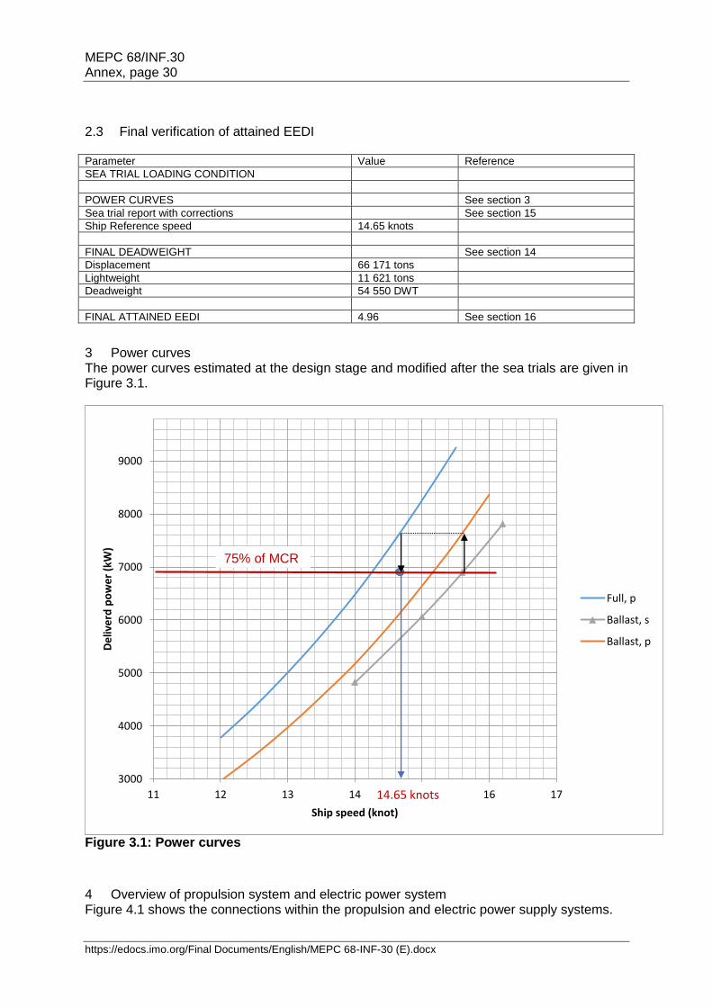
Ship Reference speed 14.65 knots
FINAL DEADWEIGHT See section 14
Displacement 66 171 tons
Lightweight 11 621 tons
Deadweight 54 550 DWT
FINAL ATTAINED EEDI 4.96 See section 16
3 Power curves The power curves estimated at the design stage and modified after the sea trials are given in Figure 3.1.
Figure 3.1: Power curves
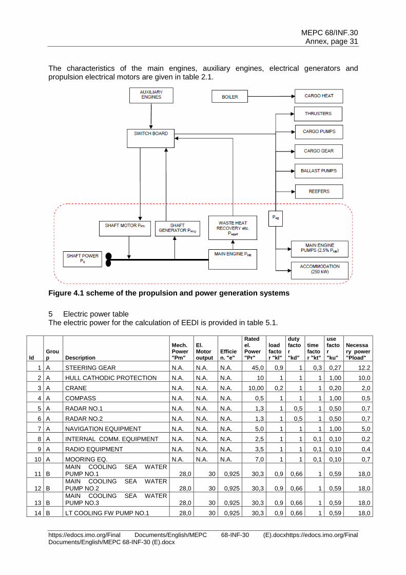
4 Overview of propulsion system and electric power system Figure 4.1 shows the connections within the propulsion and electric power supply systems.
3000
4000
5000
6000
7000
8000
9000
11 12 13 14 15 16 17
De
live
rd p
ow
er
(kW
)
Ship speed (knot)
Full, p
Ballast, s
Ballast, p
14.65 knots
75% of MCR
MEPC 68/INF.30 Annex, page 31
https://edocs.imo.org/Final Documents/English/MEPC 68-INF-30 (E).docxhttps://edocs.imo.org/Final Documents/English/MEPC 68-INF-30 (E).docx
The characteristics of the main engines, auxiliary engines, electrical generators and propulsion electrical motors are given in table 2.1.
Figure 4.1 scheme of the propulsion and power generation systems
5 Electric power table The electric power for the calculation of EEDI is provided in table 5.1.
Id Group Description
Mech. Power "Pm"
El. Motor output
Efficien. "e"
Rated el. Power "Pr"
load factor "kl"
duty factor "kd"
time factor "kt"
use factor "ku"
Necessary power "Pload"
1 A STEERING GEAR N.A. N.A. N.A. 45,0 0,9 1 0,3 0,27 12.2
2 A HULL CATHODIC PROTECTION N.A. N.A. N.A. 10 1 1 1 1,00 10,0
3 A CRANE N.A. N.A. N.A. 10,00 0,2 1 1 0,20 2,0
4 A COMPASS N.A. N.A. N.A. 0,5 1 1 1 1,00 0,5
5 A RADAR NO.1 N.A. N.A. N.A. 1,3 1 0,5 1 0,50 0,7
6 A RADAR NO.2 N.A. N.A. N.A. 1,3 1 0,5 1 0,50 0,7
7 A NAVIGATION EQUIPMENT N.A. N.A. N.A. 5,0 1 1 1 1,00 5,0
8 A INTERNAL COMM. EQUIPMENT N.A. N.A. N.A. 2,5 1 1 0,1 0,10 0,2
9 A RADIO EQUIPMENT N.A. N.A. N.A. 3,5 1 1 0,1 0,10 0,4
10 A MOORING EQ. N.A. N.A. N.A. 7,0 1 1 0,1 0,10 0,7
11 B MAIN COOLING SEA WATER PUMP NO.1 28,0 30 0,925 30,3 0,9 0,66 1 0,59 18,0
12 B MAIN COOLING SEA WATER PUMP NO.2 28,0 30 0,925 30,3 0,9 0,66 1 0,59 18,0
13 B MAIN COOLING SEA WATER PUMP NO.3 28,0 30 0,925 30,3 0,9 0,66 1 0,59 18,0
14 B LT COOLING FW PUMP NO.1 28,0 30 0,925 30,3 0,9 0,66 1 0,59 18,0
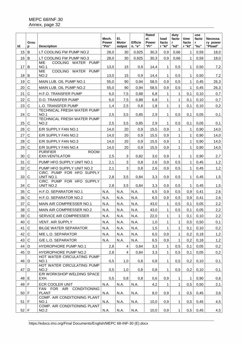
MEPC 68/INF.30 Annex, page 32
https://edocs.imo.org/Final Documents/English/MEPC 68-INF-30 (E).docx
Id Group Description
Mech. Power "Pm"
El. Motor output
Efficien. "e"
Rated el. Power "Pr"
load factor "kl"
duty factor "kd"
time factor "kt"
use factor "ku"
Necessary power "Pload"
15 B LT COOLING FW PUMP NO.2 28,0 30 0,925 30,3 0,9 0,66 1 0,59 18,0
16 B LT COOLING FW PUMP NO.3 28,0 30 0,925 30,3 0,9 0,66 1 0,59 18,0
17 B M/E COOLING WATER PUMP NO.1 13,0 15 0,9 14,4 1 0,5 1 0,50 7,2
18 B M/E COOLING WATER PUMP NO.2 13,0 15 0,9 14,4 1 0,5 1 0,50 7,2
19 C MAIN LUB. OIL PUMP NO.1 55,0 90 0,94 58,5 0,9 0,5 1 0,45 26,3
20 C MAIN LUB. OIL PUMP NO.2 55,0 90 0,94 58,5 0,9 0,5 1 0,45 26,3
21 C H.F.O. TRANSFER PUMP 6,0 7,5 0,88 6,8 1 1 0,1 0,10 0,7
22 C D.O. TRANSFER PUMP 6,0 7,5 0,88 6,8 1 1 0,1 0,10 0,7
23 C L.O. TRANSFER PUMP 1,4 2,5 0,8 1,8 1 1 0,1 0,10 0,2
24 C TECHNICAL FRESH WATER PUMP NO.1 2,5 3,5 0,85 2,9 1 0,5 0,1 0,05 0,1
25 C TECHNICAL FRESH WATER PUMP NO.2 2,5 3,5 0,85 2,9 1 0,5 0,1 0,05 0,1
26 C E/R SUPPLY FAN NO.1 14,0 20 0,9 15,5 0,9 1 1 0,90 14,0
27 C E/R SUPPLY FAN NO.2 14,0 20 0,9 15,5 0,9 1 1 0,90 14,0
28 C E/R SUPPLY FAN NO.3 14,0 20 0,9 15,5 0,9 1 1 0,90 14,0
29 C E/R SUPPLY FAN NO.4 14,0 20 0,9 15,5 0,9 1 1 0,90 14,0
30 C PURIFIER ROOM EXH.VENTILATOR 2,5 3 0,82 3,0 0,9 1 1 0,90 2,7
31 C PUMP HFO SUPPLY UNIT NO.1 2,1 3 0,8 2,6 0,9 0,5 1 0,45 1,2
32 C PUMP HFO SUPPLY UNIT NO.2 2,1 3 0,8 2,6 0,9 0,5 1 0,45 1,2
33 C CIRC. PUMP FOR HFO SUPPLY UNIT NO.1 2,8 3,5 0,84 3,3 0,9 0,5 1 0,45 1,5
34 C CIRC. PUMP FOR HFO SUPPLY UNIT NO.2 2,8 3,5 0,84 3,3 0,9 0,5 1 0,45 1,5
35 C H.F.O. SEPARATOR NO.1 N.A. N.A. N.A. 6,5 0,9 0,5 0,9 0,41 2,6
36 C H.F.O. SEPARATOR NO.2 N.A. N.A. N.A. 6,5 0,9 0,5 0,9 0,41 2,6
37 C MAIN AIR COMPRESSER NO.1 N.A. N.A. N.A. 43,0 1 0,5 0,1 0,05 2,2
38 C MAIN AIR COMPRESSER NO.2 N.A. N.A. N.A. 43,0 1 0,5 0,1 0,05 2,2
39 C SERVICE AIR COMPRESSER N.A. N.A. N.A. 22,0 1 1 0,1 0,10 2,2
40 C VENT. AIR SUPPLY N.A. N.A. N.A. 1,0 1 1 0,5 0,50 0,1
41 C BILGE WATER SEPARATOR N.A. N.A. N.A. 1,5 1 1 0,1 0,10 0,2
42 C M/E L.O. SEPARATOR N.A. N.A. N.A. 6,5 0,9 1 0,2 0,18 1,2
43 C G/E L.O. SEPARATOR N.A. N.A. N.A. 6,5 0,9 1 0,2 0,18 1,2
44 D HYDROPHORE PUMP NO.1 2,8 4 0,84 3,3 1 0,5 0,1 0,05 0,2
45 D HYDROPHORE PUMP NO.2 2,8 4 0,84 3,3 1 0,5 0,1 0,05 0,2
46 D HOT WATER CIRCULATING PUMP NO.1 0,5 1,0 0,8 0,8 1 0,5 0,2 0,10 0,1
47 D HOT WATER CIRCULATING PUMP NO.2 0,5 1,0 0,8 0,8 1 0,5 0,2 0,10 0,1
48 E E/R WORKSHOP WELDING SPACE EXH. 0,5 0,8 0,8 0,6 0,9 1 1 0,90 0,6
49 F ECR COOLER UNIT N.A. N.A. N.A. 4,2 1 1 0,5 0,50 2,1
50 F FAN FOR AIR CONDITIONING PLANT N.A. N.A. N.A. 8,0 0,9 1 0,5 0,45 3,6
51 F COMP. AIR CONDITIONING PLANT NO.1 N.A. N.A. N.A. 10,0 0,9 1 0,5 0,45 4,5
52 F COMP. AIR CONDITIONING PLANT NO.2 N.A. N.A. N.A. 10,0 0,9 1 0,5 0,45 4,5
MEPC 68/INF.30 Annex, page 33
https://edocs.imo.org/Final Documents/English/MEPC 68-INF-30 (E).docxhttps://edocs.imo.org/Final Documents/English/MEPC 68-INF-30 (E).docx
Id Group Description
Mech. Power "Pm"
El. Motor output
Efficien. "e"
Rated el. Power "Pr"
load factor "kl"
duty factor "kd"
time factor "kt"
use factor "ku"
Necessary power "Pload"
53 F COMP. AIR CONDITIONING PLANT NO.3 N.A. N.A. N.A. 10,0 0,9 1 0,5 0,45 4,5
54 F COMP. AIR CONDITIONING PLANT NO.4 N.A. N.A. N.A. 10,0 0,9 1 0,5 0,45 4,5
55 G FAN FOR GALLEY AIR COND. PLANT N.A. N.A. N.A. 1,5 0,9 1 0,5 0,45 0,7
56 G COMP. FOR GALLEY AIR COND. PLANT N.A. N.A. N.A. 3,5 0,9 1 0,5 0,45 1,6
57 G REF. COMPRESSOR NO.1 N.A. N.A. N.A. 4,0 1 0,5 0,1 0,05 0,2
58 G REF. COMPRESSOR NO.2 N.A. N.A. N.A. 4,0 1 0,5 0,1 0,05 0,2
59 G GALLEY EQUIPMENT N.A. N.A. N.A. 80,0 0,5 1 0,1 0,05 4,0
60 H VAC. COLLECTION SYSTEM 2,4 3,0 0,8 3,0 1 1 1 1,00 3,0
61 H GALLEY EXH. 1,2 1,5 0,8 1,5 1 1 1 1,00 1,5
62 H LAUNDRY EXH. 0,1 0,15 0,8 0,1 1 1 1 1,00 0,1
63 H SEWAGE TREATMENT N.A. N.A. N.A. 4,5 1 1 0,1 0,10 0,5
64 H SEWAGE DISCHARGE 3 7,5 0,88 3,4 0,9 1 0,1 0,09 0,3
65 I ACCOMMODATION LIGHTING N.A. N.A. N.A. 16,0 1 1 0,5 0,5 8,0
66 I E/R LIGHTING N.A. N.A. N.A. 18,0 1 1 1 1,00 18,0
67 I NAVIGATION LIGHTING N.A. N.A. N.A. 0,9 1 0,5 1 0,50 0,4
68 I BACK. NAV. LIGHTING N.A. N.A. N.A. 0,9 1 0,5 1 0,50 0,4
TOTAL POWER 354,0
PAE = Total Power / (average efficiency of generators) = 354/0.93 = 381 kW
Table 5.1: Electric power table for calculation of PAE
6 TOWING Tank test organization quality system Towing tank tests will be performed in TEST corp. The quality control system of the towing tank test organization TEST corp. has been documented previously (see report 100 for the ship hull No. 12345) and the quality manual and calibration records are available to the verifier. The measuring equipment has not been modified since the issue of report 100 and is listed in table 6.1.
Manufacturer Model Series Lab. Id. status
Propeller dynamometer
B&N 6001 300 125-2 Calibrated 01/01/2011
…
Table 6.1: List of measuring equipment
7 Estimation process of power curves at design stage
7.1 Test procedure The tests and their analysis are conducted by TEST corp. applying their standard correlation method (document is given in annex 1). The method is based on thrust identity and references ITTC Recommended Procedure 7.5 - 02 - 03 -1.4 ITTC 1978 Trial Prediction Method (in its latest reviewed version of 2011), with prediction of the full scale rpm and delivered power by use of the CP – CN correction factors.
MEPC 68/INF.30 Annex, page 34
https://edocs.imo.org/Final Documents/English/MEPC 68-INF-30 (E).docx
The results are based on a Resistance Test, a Propulsion Test and use the Open Water Characteristics of the model propeller used during the tests and the Propeller Open Water Characteristics of the final propeller given in 7.4. Results of the resistance tests and propulsion tests of the ship model are given in the report of TEST corp. given in annex 2.
7.2 Speed prediction The ship delivered power PD and rate of revolutions nS are determined from the following equations:
𝑃𝐷 = 𝐶𝑃 . 𝑃𝐷𝑆
𝑛𝑇 = 𝐶𝑁. 𝑛𝑆 Where CN and CP are experience-based factors and PDS (resp. nS) are the delivered power (resp. rpm) obtained from the analysis of the towing tank tests. The ship total resistance coefficient CTS is given by:
𝐶𝑇𝑆 = 𝑆𝑆 + 𝑆𝐵𝐾
𝑆𝑆. [(1 + 𝑘). 𝐶𝐹𝑆 + ∆𝐶𝐹] + 𝐶𝑅 + 𝐶𝐴𝐴𝑆 + 𝐶𝐴𝑝𝑝𝑆
Where: SS: ship hull wetted surface, here 9886 m2 SBK: wetted surface of bilge keels k: form factor. Here 1+k = 1.38 over the speed range, determined according to ITTC
standard procedure 7.5-02-02-01 CFS: ship frictional resistance coefficient (computed according to ITTC 1957 formula) ∆CF: roughness allowance, computed according to Bowden-Davison formula. Here ∆CF
= 0.000339 CR: residual resistance coefficient CAAS: air resistance coefficient CAppS: ship appendages (propeller boss cap fins) resistance coefficient, computed as
provided in annex 2. The air resistance coefficient is computed according to the following formula:
𝐶𝐴𝐴𝑆 = 𝐶𝐷𝐴.𝜌𝐴. 𝐴𝑉𝑆
𝜌𝑆. 𝑆𝑆
Where: CDA is the air drag coefficient, here 0.8 ρA and ρS are the air density and water density, respectively AVS is the projected wind area, here 820 m2 CAAS = 7.9.10-5 The delivered power PD results of the towing tank tests are summarized in table 7.1 for the EEDI condition (scantling draft) and in table 7.2 for the sea trial condition (light ballast draft). Model reference: SX100 - model scale: 40
Loading condition: EEDI loading condition (12.70 m draft)
Resistance test: R001
Propulsion test: P001 Model propeller: Prop01
Ship speed V (knot)
Wake factor wTM-wTS
Propeller thrust TS (kN)
Propeller torque QS (kNm)
rpm on ship nS
Delivered Power PD (kW)
12 0.098 522 467 78 3781
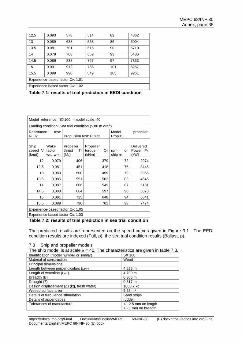
MEPC 68/INF.30 Annex, page 35
https://edocs.imo.org/Final Documents/English/MEPC 68-INF-30 (E).docxhttps://edocs.imo.org/Final Documents/English/MEPC 68-INF-30 (E).docx
12.5 0.093 578 514 82 4362
13 0.089 638 563 86 5004
13.5 0.081 701 615 90 5710
14 0.079 768 669 93 6486
14.5 0.086 838 727 97 7333
15 0.091 912 786 101 8257
15.5 0.099 990 849 105 9261
Experience-based factor CP: 1.01
Experience based factor CN: 1.02
Table 7.1: results of trial prediction in EEDI condition
Model reference: SX100 - model scale: 40
Loading condition: Sea trial condition (5.80 m draft)
Resistance test: R002 Propulsion test: POO2
Model propeller: Prop01
Ship speed V (knot)
Wake factor wTM-wTS
Propeller thrust TS (kN)
Propeller torque QS (kNm)
rpm on ship nS
Delivered Power PD (kW)
12 0,079 406 379 72 2974
12,5 0,081 451 418 76 3445
13 0,083 500 459 79 3968
13,5 0,085 551 503 83 4545
14 0,087 606 549 87 5181
14,5 0,088 664 597 90 5878
15 0,091 725 648 94 6641
15,5 0,089 790 701 98 7474
Experience-based factor CP: 1.05
Experience based factor CN: 1.03
Table 7.2: results of trial prediction in sea trial condition The predicted results are represented on the speed curves given in Figure 3.1. The EEDI condition results are indexed (Full, p), the sea trial condition results (Ballast, p).
7.3 Ship and propeller models The ship model is at scale λ = 40. The characteristics are given in table 7.3. Identification (model number or similar) SX 100
Material of construction Wood
Principal dimensions
Length between perpendiculars (LPP) 4.625 m
Length of waterline (LWL) 4.700 m
Breadth (B) 0.806 m
Draught (T) 0.317 m
Design displacement (Δ) (kg, fresh water) 1008.7 kg
Wetted surface area 6.25 m2
Details of turbulence stimulation Sand strips
Details of appendages rudder
Tolerances of manufacture +/- 2.5 mm on length +/- 1 mm on breadth
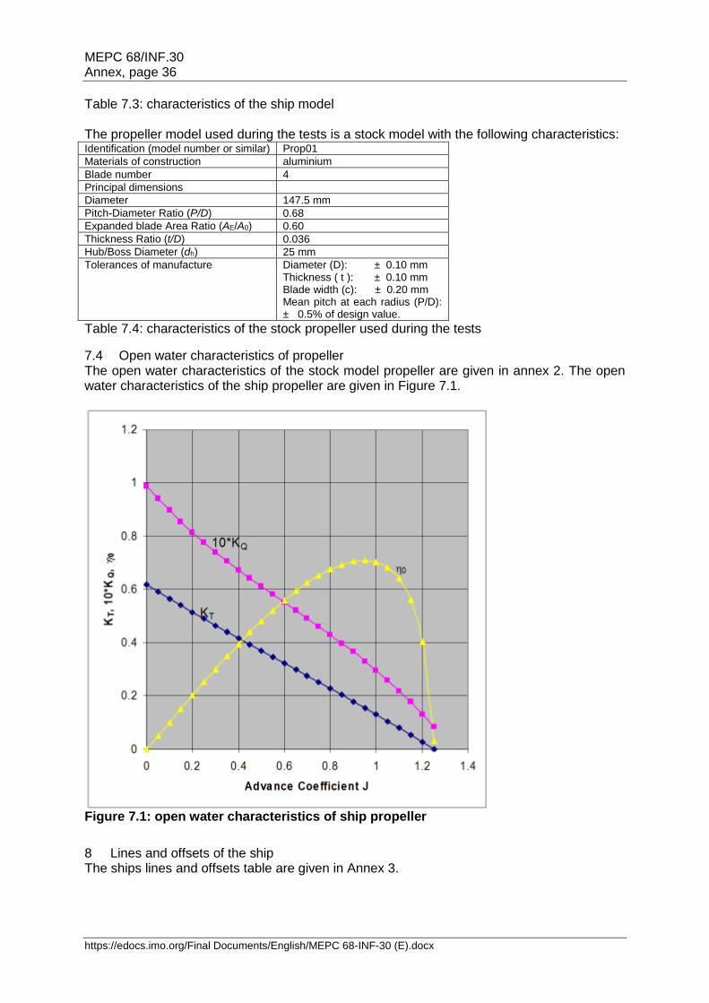
MEPC 68/INF.30 Annex, page 36
https://edocs.imo.org/Final Documents/English/MEPC 68-INF-30 (E).docx
Table 7.3: characteristics of the ship model The propeller model used during the tests is a stock model with the following characteristics: Identification (model number or similar) Prop01
Materials of construction aluminium
Blade number 4
Principal dimensions
Diameter 147.5 mm
Pitch-Diameter Ratio (P/D) 0.68
Expanded blade Area Ratio (AE/A0) 0.60
Thickness Ratio (t/D) 0.036
Hub/Boss Diameter (dh) 25 mm
Tolerances of manufacture Diameter (D): ± 0.10 mm Thickness ( t ): ± 0.10 mm Blade width (c): ± 0.20 mm Mean pitch at each radius (P/D): ± 0.5% of design value.
Table 7.4: characteristics of the stock propeller used during the tests
7.4 Open water characteristics of propeller The open water characteristics of the stock model propeller are given in annex 2. The open water characteristics of the ship propeller are given in Figure 7.1.
Figure 7.1: open water characteristics of ship propeller
8 Lines and offsets of the ship The ships lines and offsets table are given in Annex 3.
MEPC 68/INF.30 Annex, page 37
https://edocs.imo.org/Final Documents/English/MEPC 68-INF-30 (E).docxhttps://edocs.imo.org/Final Documents/English/MEPC 68-INF-30 (E).docx
9 Description of energy saving equipment
9.1 Energy saving equipment of which effects are expressed as PAEeff(i) and/or Peff(i) in the EEDI calculation formula
None here.
9.2 Other energy saving equipment The propeller boss cap fins are described in annex 4.
10 Justification of SFC (documents attached to NOx technical file of the parent engine)
10.1 Main engine The shop test report for the parent main engine is provided in annex 5.1. The SFOC has been corrected to ISO conditions.
10.2 Auxiliary engine The technical file of the EIAPP certificate of the auxiliary engines is provided in annex 5.2. The SFOC has been corrected to ISO conditions.
11 Calculation of attained EEDI at design stage
11.1 Input parameters and definitions The EEDI quantities and intermediate calculations are listed in table 11.1: EEDI quantity
Value Remarks
CFME 3.206 Marine Diesel oil is used for shop test of the main engine
PME 6 900 kW No shaft generator installed ( PPTO = 0) MCR is 9200 kW PME = 0.75x9200 = 6 900 kW
SFCME 171 g/kWh According to parent engine shop test report in ISO conditions (see 10.1)
CFAE 3.206 Marine diesel oil is used for shop test of the auxiliary engine
PPTI 0 No shaft motor installed
PAE 381 kW MCR of the engine is 9200 kW, less than 10000kW
𝑃𝐴𝐸 = 0.05. (∑ 𝑀𝐶𝑅𝑀𝐸𝑖
𝑛𝑀𝐸
𝑖=1
+∑ 𝑃𝑃𝑇𝐼(𝑖)
𝑛𝑃𝑇𝐼𝑖=1
0.75)
PAE = 0.05*9200 = 460 kW According to electric power table included in table 5.1, ∑Pload(i) = 354 kW The weighted average efficiency of generators = 0.93 (KWelec/kWmech) PAE = ∑Pload(i) / 0.93 = 381 kW The difference (460 – 381) KW is expected to vary EEDI by slightly more than 1%, so 381 kW is considered.
SFCAE 205 g/kWh According to technical file of EIAPP certificate in ISO conditions (see 10.2)
Peff 0 No mechanical energy efficient devices The propeller boss cap fins act by reducing ship resistance
PAEeff 0 No auxiliary power reduction
feff Not relevant here (see above)
fj 1.0 The ship is a bulk carrier without ice notations. fj = 1.0
fi 1.017 No ice notation fiICE = 1.0 No voluntary structural enhancement for this ship fiVSE = 1.0 The ship has the notation Bulk carrier CSR: fiCSR = 1 + 0.08*LWTCSR / DWTCSR = 1+0.08*11590/55000 = 1.017 fi = fiICE x fiVSE x fiCSR = 1.017
fw 1.0 For attained EEDI calculation under regulation 20 and 21 of MARPOL Annex VI, fw is 1.0
fc 1.0 The ship is a bulk carrier fc = 1.0
Capacity 55000 For a bulk carrier, Capacity is deadweight = 55 000 tons
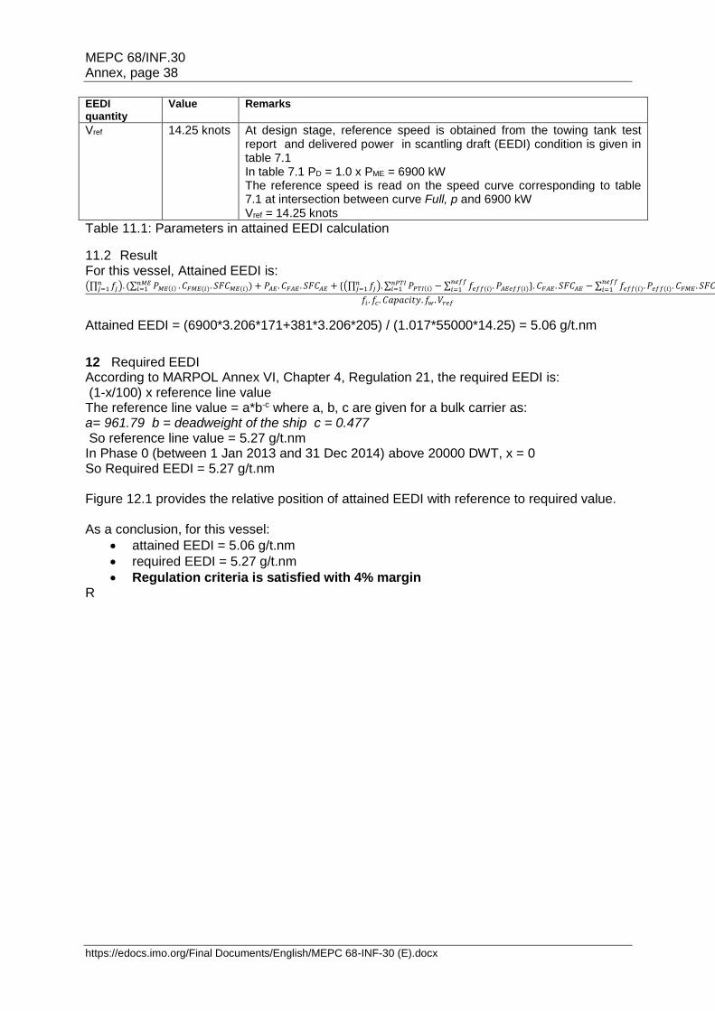
MEPC 68/INF.30 Annex, page 38
https://edocs.imo.org/Final Documents/English/MEPC 68-INF-30 (E).docx
EEDI quantity
Value Remarks
Vref 14.25 knots At design stage, reference speed is obtained from the towing tank test report and delivered power in scantling draft (EEDI) condition is given in table 7.1 In table 7.1 PD = 1.0 x PME = 6900 kW The reference speed is read on the speed curve corresponding to table 7.1 at intersection between curve Full, p and 6900 kW Vref = 14.25 knots
Table 11.1: Parameters in attained EEDI calculation
11.2 Result For this vessel, Attained EEDI is: (∏ 𝑓𝑗
𝑛𝑗=1 ). (∑ 𝑃𝑀𝐸(𝑖)
𝑛𝑀𝐸𝑖=1 . 𝐶𝐹𝑀𝐸(𝑖). 𝑆𝐹𝐶𝑀𝐸(𝑖)) + 𝑃𝐴𝐸 . 𝐶𝐹𝐴𝐸 . 𝑆𝐹𝐶𝐴𝐸 + {(∏ 𝑓𝑗
𝑛𝑗=1 ). ∑ 𝑃𝑃𝑇𝐼(𝑖) − ∑ 𝑓𝑒𝑓𝑓(𝑖). 𝑃𝐴𝐸𝑒𝑓𝑓(𝑖)}. 𝐶𝐹𝐴𝐸 . 𝑆𝐹𝐶𝐴𝐸 − ∑ 𝑓𝑒𝑓𝑓(𝑖). 𝑃𝑒𝑓𝑓(𝑖). 𝐶𝐹𝑀𝐸 . 𝑆𝐹𝐶𝑀𝐸)
𝑛𝑒𝑓𝑓𝑖=1
𝑛𝑒𝑓𝑓𝑖=1
𝑛𝑃𝑇𝐼𝑖=1
𝑓𝑖. 𝑓𝑐. 𝐶𝑎𝑝𝑎𝑐𝑖𝑡𝑦. 𝑓𝑤 . 𝑉𝑟𝑒𝑓
Attained EEDI = (6900*3.206*171+381*3.206*205) / (1.017*55000*14.25) = 5.06 g/t.nm
12 Required EEDI According to MARPOL Annex VI, Chapter 4, Regulation 21, the required EEDI is: (1-x/100) x reference line value The reference line value = a*b-c where a, b, c are given for a bulk carrier as: a= 961.79 b = deadweight of the ship c = 0.477 So reference line value = 5.27 g/t.nm In Phase 0 (between 1 Jan 2013 and 31 Dec 2014) above 20000 DWT, x = 0 So Required EEDI = 5.27 g/t.nm Figure 12.1 provides the relative position of attained EEDI with reference to required value. As a conclusion, for this vessel:
attained EEDI = 5.06 g/t.nm
required EEDI = 5.27 g/t.nm
Regulation criteria is satisfied with 4% margin R
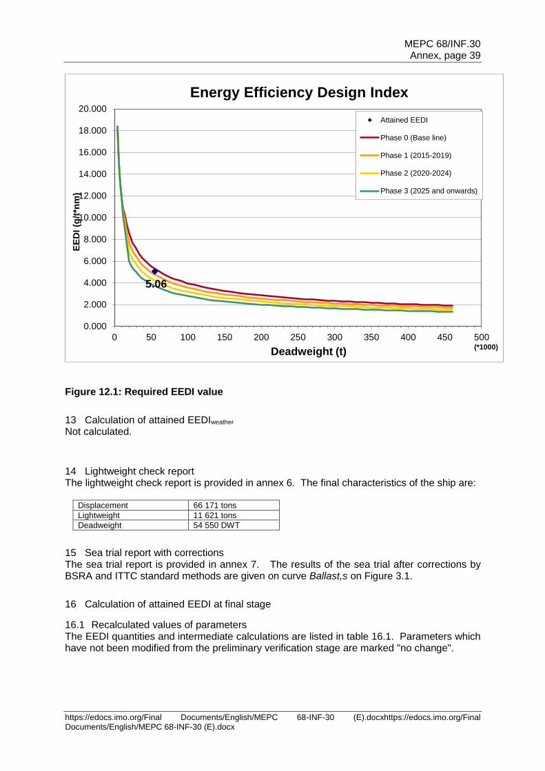
MEPC 68/INF.30 Annex, page 39
https://edocs.imo.org/Final Documents/English/MEPC 68-INF-30 (E).docxhttps://edocs.imo.org/Final Documents/English/MEPC 68-INF-30 (E).docx
Figure 12.1: Required EEDI value
13 Calculation of attained EEDIweather Not calculated.
14 Lightweight check report The lightweight check report is provided in annex 6. The final characteristics of the ship are:
Displacement 66 171 tons
Lightweight 11 621 tons
Deadweight 54 550 DWT
15 Sea trial report with corrections The sea trial report is provided in annex 7. The results of the sea trial after corrections by BSRA and ITTC standard methods are given on curve Ballast,s on Figure 3.1.
16 Calculation of attained EEDI at final stage
16.1 Recalculated values of parameters The EEDI quantities and intermediate calculations are listed in table 16.1. Parameters which have not been modified from the preliminary verification stage are marked "no change".
5.06
0.000
2.000
4.000
6.000
8.000
10.000
12.000
14.000
16.000
18.000
20.000
0 50 100 150 200 250 300 350 400 450 500
EE
DI
(g/t
*nm
)
Deadweight (t)(*1000)
Energy Efficiency Design Index
Attained EEDI
Phase 0 (Base line)
Phase 1 (2015-2019)
Phase 2 (2020-2024)
Phase 3 (2025 and onwards)
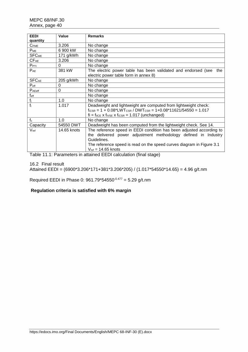
MEPC 68/INF.30 Annex, page 40
https://edocs.imo.org/Final Documents/English/MEPC 68-INF-30 (E).docx
EEDI quantity
Value Remarks
CFME 3.206 No change
PME 6 900 kW No change
SFCME 171 g/kWh No change
CFAE 3.206 No change
PPTI 0 No change
PAE 381 kW The electric power table has been validated and endorsed (see the electric power table form in annex 8)
SFCAE 205 g/kWh No change
Peff 0 No change
PAEeff 0 No change
feff No change
fj 1.0 No change
fi 1.017 Deadweight and lightweight are computed from lightweight check: fiCSR = 1 + 0.08*LWTCSR / DWTCSR = 1+0.08*11621/54550 = 1.017 fi = fiICE x fiVSE x fiCSR = 1.017 (unchanged)
fc 1.0 No change
Capacity 54550 DWT Deadweight has been computed from the lightweight check. See 14.
Vref 14.65 knots The reference speed in EEDI condition has been adjusted according to the delivered power adjustment methodology defined in Industry Guidelines. The reference speed is read on the speed curves diagram in Figure 3.1 Vref = 14.65 knots
Table 11.1: Parameters in attained EEDI calculation (final stage)
16.2 Final result Attained EEDI = (6900*3.206*171+381*3.206*205) / (1.017*54550*14.65) = 4.96 g/t.nm Required EEDI in Phase 0: 961.79*54550-0.477 = 5.29 g/t.nm Regulation criteria is satisfied with 6% margin
MEPC 68/INF.30 Annex, page 41
https://edocs.imo.org/Final Documents/English/MEPC 68-INF-30 (E).docxhttps://edocs.imo.org/Final Documents/English/MEPC 68-INF-30 (E).docx
List of annexes to the Document
Annex 1 Standard model-ship extrapolation and correlation method
Annex 2 Towing tank tests report
Annex 3 Ship lines and offsets table
Annex 4 Description of energy saving equipment
Annex 5 5.1 NOx Technical File of main engine(s) 5.2 NOx Technical File of auxiliary engines
Annex 6 Lightweight check report
Annex 7 Sea trials report
Annex 8 EPT-EEDI form
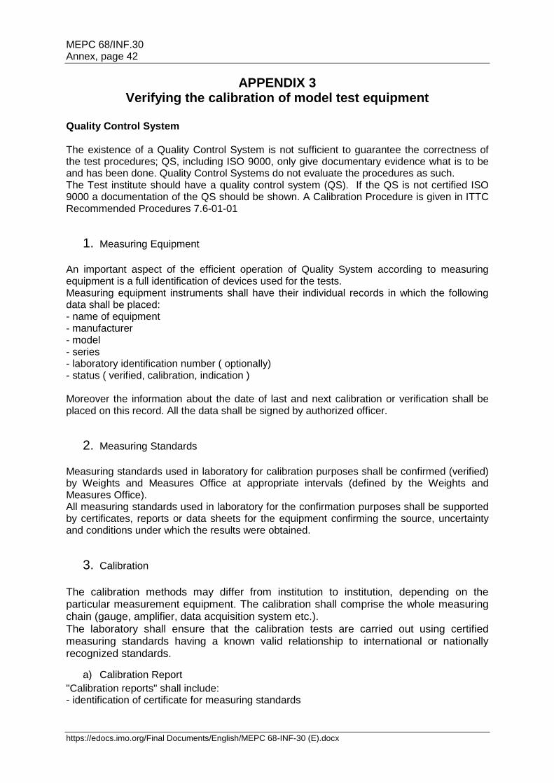
MEPC 68/INF.30 Annex, page 42
https://edocs.imo.org/Final Documents/English/MEPC 68-INF-30 (E).docx
APPENDIX 3 Verifying the calibration of model test equipment
Quality Control System The existence of a Quality Control System is not sufficient to guarantee the correctness of the test procedures; QS, including ISO 9000, only give documentary evidence what is to be and has been done. Quality Control Systems do not evaluate the procedures as such. The Test institute should have a quality control system (QS). If the QS is not certified ISO 9000 a documentation of the QS should be shown. A Calibration Procedure is given in ITTC Recommended Procedures 7.6-01-01
1. Measuring Equipment
An important aspect of the efficient operation of Quality System according to measuring equipment is a full identification of devices used for the tests. Measuring equipment instruments shall have their individual records in which the following data shall be placed: - name of equipment - manufacturer - model - series - laboratory identification number ( optionally) - status ( verified, calibration, indication ) Moreover the information about the date of last and next calibration or verification shall be placed on this record. All the data shall be signed by authorized officer.
2. Measuring Standards
Measuring standards used in laboratory for calibration purposes shall be confirmed (verified) by Weights and Measures Office at appropriate intervals (defined by the Weights and Measures Office). All measuring standards used in laboratory for the confirmation purposes shall be supported by certificates, reports or data sheets for the equipment confirming the source, uncertainty and conditions under which the results were obtained.
3. Calibration
The calibration methods may differ from institution to institution, depending on the particular measurement equipment. The calibration shall comprise the whole measuring chain (gauge, amplifier, data acquisition system etc.). The laboratory shall ensure that the calibration tests are carried out using certified measuring standards having a known valid relationship to international or nationally recognized standards.
a) Calibration Report
"Calibration reports" shall include: - identification of certificate for measuring standards
MEPC 68/INF.30 Annex, page 43
https://edocs.imo.org/Final Documents/English/MEPC 68-INF-30 (E).docxhttps://edocs.imo.org/Final Documents/English/MEPC 68-INF-30 (E).docx
- description of environmental conditions - calibration factor or calibration curve - uncertainty of measurement - minimum and maximum capacity" for which the error of measuring instrument is within
specified (acceptable) limits.
b) Intervals of Confirmation
The measuring equipment (including measuring standards) shall be confirmed at appropriate (usually periodical) intervals, established on the basis of their stability, purpose and wear. The intervals shall be such that confirmation is carried out again prior to any probable change in the equipment accuracy, which is important for the equipment reliability. Depending on the results of preceding calibrations, the confirmation period may be shortened, if necessary, to ensure the continuous accuracy of the measuring equipment. The laboratory shall have specific objective criteria for decisions concerning the choice of intervals of confirmation.
c) Non - Conforming Equipment
Any item of measuring equipment - that has suffered damage, - that has been overloaded or mishandled, - that shows any malfunction, - whose proper functioning is subject to doubt, - that has exceeded its designated confirmation interval, or - the integrity of whose seal has been violated, shall be removed from service by
segregation, clear labelling or cancelling. Such equipment shall not be returned to service until the reasons for its nonconformity have been eliminated and it is confirmed again. If the results of calibration prior to any adjustment or repair were such as to indicate a risk of significant errors in any of the measurements made with the equipment before the calibration, the laboratory shall take the necessary corrective action.
4. Instrumentation
Especially the documentation on the calibration of the following Instrumentation should be shown.
a) Carriage Speed
The carriage speed is to be calibrated as a distance against time. Period between the calibrations is to be in accordance with the internal procedure of the towing tank test organization.
b) Water Temperature
Measured by calibrated thermometer with certificate (accuracy 0.1°C).
c) Trim Measurement
Calibrated against a length standard. Period between the calibrations is to be in accordance with the internal procedure of the towing tank test organization.
d) Resistance Test
Resistance Test is a force measurement. It is to be calibrated against a standard weight. Calibration normally before each test series.

MEPC 68/INF.30 Annex, page 44
https://edocs.imo.org/Final Documents/English/MEPC 68-INF-30 (E).docx
e) Propulsion Test
During Self Propulsion Test torque, thrust and rate of revolutions are measured. Thrust and Torque are calibrated against a standard weight. Rate of revolution is normally measured by a pulse tachometer and an electronic counter which can be calibrated e.g. by an oscillograph. Period between the calibrations is to be in accordance with the internal procedure of the towing tank test organization.
f) Propeller Open Water Test
During Propeller Open Water Test torque, thrust and rate of revolutions are measured. Thrust and Torque are calibrated against a standard weight. Rate of revolution is normally measured by a pulse tachometer and an electronic counter which can be calibrated e.g. by an oscillograph. Period between the calibrations is to be in accordance with the internal procedure of the towing tank test organization. Examples of documentation sheets are given in the Annexes 1 and 2:
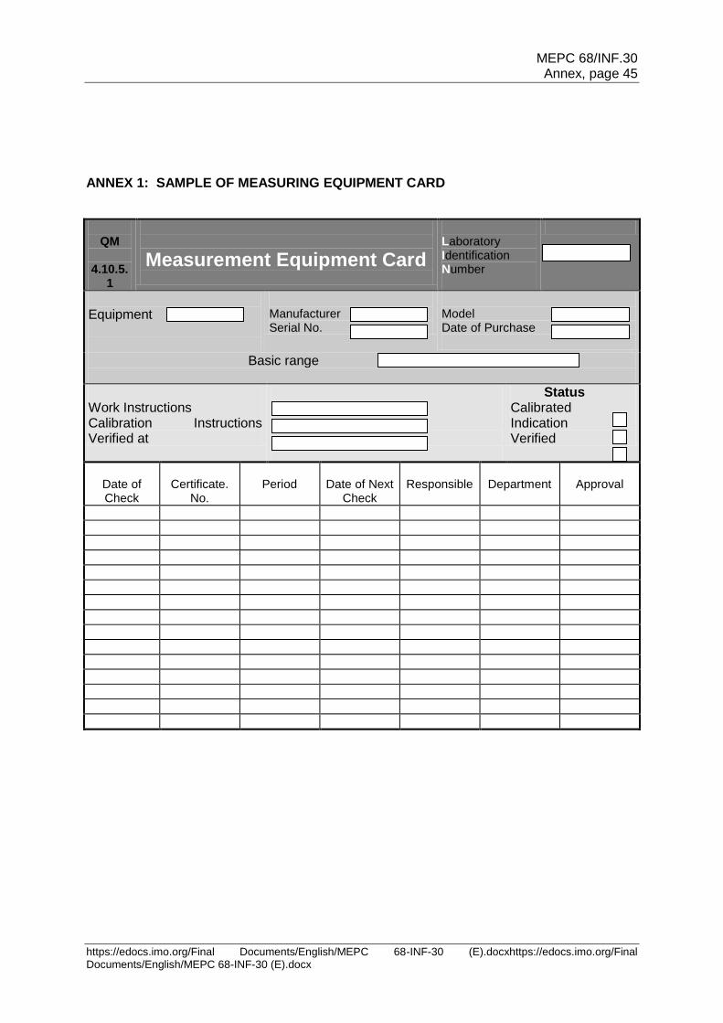
MEPC 68/INF.30 Annex, page 45
https://edocs.imo.org/Final Documents/English/MEPC 68-INF-30 (E).docxhttps://edocs.imo.org/Final Documents/English/MEPC 68-INF-30 (E).docx
ANNEX 1: SAMPLE OF MEASURING EQUIPMENT CARD
QM
4.10.5.
1
Measurement Equipment Card
Laboratory Identification Number
Equipment
Manufacturer Serial No.
Model Date of Purchase
Basic range
Work Instructions Calibration Instructions Verified at
Status Calibrated Indication Verified
Date of Check
Certificate.
No.
Period
Date of Next
Check
Responsible
Department
Approval
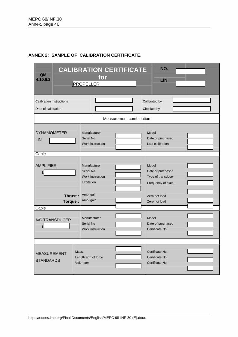
MEPC 68/INF.30 Annex, page 46
https://edocs.imo.org/Final Documents/English/MEPC 68-INF-30 (E).docx
ANNEX 2: SAMPLE OF CALIBRATION CERTIFICATE.
QM 4.10.6.2
CALIBRATION CERTIFICATE for
NO.
LIN
Calibration Instructions Date of calibration
Calibrated by : Checked by :
Measurement combination
DYNAMOMETER
LIN
Manufacturer
Serial No
Work instruction
Model
Date of purchased
Last calibration
Cable
AMPLIFIER
LIN
Thrust :
Torque :
Manufacturer
Serial No
Work instruction
Excitation
Amp. gain
Amp. gain
Model
Date of purchased
Type of transducer
Frequency of excit.
Zero not load
Zero not load
Cable
A/C TRANSDUCER
LIN
Manufacturer
Serial No
Work instruction
Model
Date of purchased
Certificate No
MEASUREMENT
STANDARDS
Mass
Length arm of force
Voltmeter
Certificate No
Certificate No
Certificate No
PROPELLER DYNAMOMETER
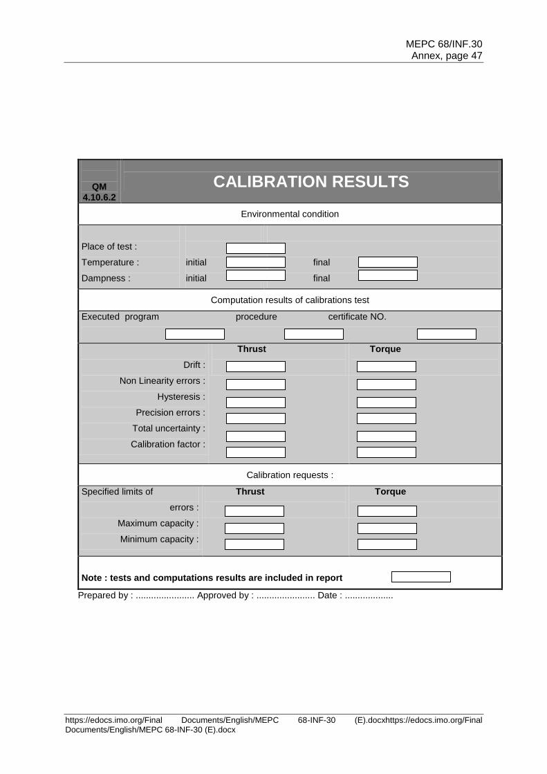
MEPC 68/INF.30 Annex, page 47
https://edocs.imo.org/Final Documents/English/MEPC 68-INF-30 (E).docxhttps://edocs.imo.org/Final Documents/English/MEPC 68-INF-30 (E).docx
QM 4.10.6.2
CALIBRATION RESULTS
Environmental condition
Place of test :
Temperature :
Dampness :
initial
initial
final
final
Computation results of calibrations test
Executed program procedure certificate NO.
Drift :
Non Linearity errors :
Hysteresis :
Precision errors :
Total uncertainty :
Calibration factor :
Thrust
Torque
Calibration requests :
Specified limits of
errors :
Maximum capacity :
Minimum capacity :
Thrust
Torque
Note : tests and computations results are included in report
Prepared by : ....................... Approved by : ....................... Date : ...................
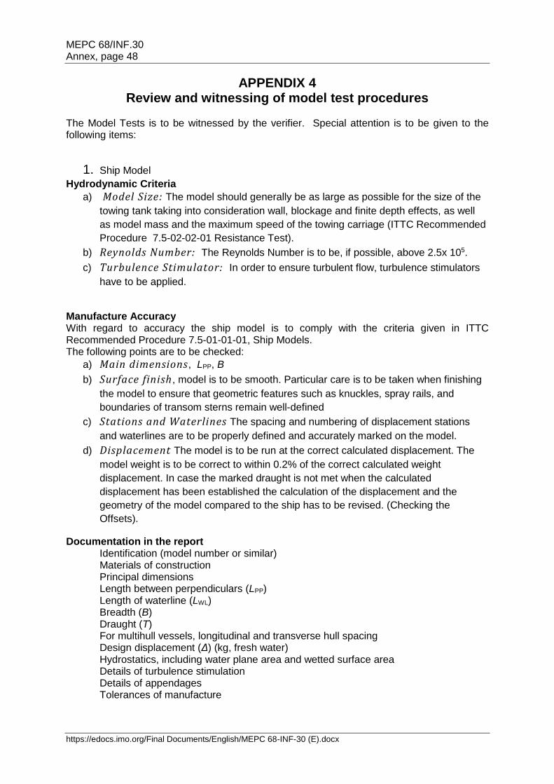
MEPC 68/INF.30 Annex, page 48
https://edocs.imo.org/Final Documents/English/MEPC 68-INF-30 (E).docx
APPENDIX 4 Review and witnessing of model test procedures
The Model Tests is to be witnessed by the verifier. Special attention is to be given to the following items:
1. Ship Model
Hydrodynamic Criteria
a) Model Size: The model should generally be as large as possible for the size of the
towing tank taking into consideration wall, blockage and finite depth effects, as well
as model mass and the maximum speed of the towing carriage (ITTC Recommended
Procedure 7.5-02-02-01 Resistance Test).
b) Reynolds Number: The Reynolds Number is to be, if possible, above 2.5x 10⁵.
c) Turbulence Stimulator: In order to ensure turbulent flow, turbulence stimulators
have to be applied.
Manufacture Accuracy With regard to accuracy the ship model is to comply with the criteria given in ITTC Recommended Procedure 7.5-01-01-01, Ship Models. The following points are to be checked:
a) Main dimensions, LPP, B
b) Surface finish, model is to be smooth. Particular care is to be taken when finishing
the model to ensure that geometric features such as knuckles, spray rails, and
boundaries of transom sterns remain well-defined
c) Stations and Waterlines The spacing and numbering of displacement stations
and waterlines are to be properly defined and accurately marked on the model.
d) Displacement The model is to be run at the correct calculated displacement. The
model weight is to be correct to within 0.2% of the correct calculated weight
displacement. In case the marked draught is not met when the calculated
displacement has been established the calculation of the displacement and the
geometry of the model compared to the ship has to be revised. (Checking the
Offsets).
Documentation in the report Identification (model number or similar) Materials of construction Principal dimensions Length between perpendiculars (LPP) Length of waterline (LWL) Breadth (B) Draught (T) For multihull vessels, longitudinal and transverse hull spacing Design displacement (Δ) (kg, fresh water) Hydrostatics, including water plane area and wetted surface area Details of turbulence stimulation Details of appendages Tolerances of manufacture

MEPC 68/INF.30 Annex, page 49
https://edocs.imo.org/Final Documents/English/MEPC 68-INF-30 (E).docxhttps://edocs.imo.org/Final Documents/English/MEPC 68-INF-30 (E).docx
2. Propeller Model
The Manufacturing Tolerances of Propellers for Propulsion Tests are given IN ITTC Recommended Procedures 7.5-01-01-01, Ship Models Chapter 3.1.2. Attention: Procedure 7.5 – 01-02-02 Propeller Model Accuracy is asking for higher standards which are applicable for cavitation tests and not required for self-propulsion tests. Propeller Model Accuracy Stock Propellers During the "stock-propeller" testing phase, the geometrical particulars of the final design propeller are normally not known. Therefore, the stock propeller pitch (in case of CPP) is recommended to be adjusted to the anticipated propeller shaft power and design propeller revolutions. (ITTC Recommended Procedure 7.5-02-03-01.1 Propulsion/Bollard Pull Test). Adjustable Pitch Propellers Before the Tests the pitch adjustment is to be controlled. Final Propellers Propellers having diameter (D) typically from 150 mm to 300 mm is to be finished to the following tolerances: Diameter (D) ± 0.10 mm Thickness (t) ± 0.10 mm Blade width (c) ± 0.20 mm Mean pitch at each radius (P/D): ± 0.5% of de-sign value.
Special attention is to be paid to the shaping accuracy near the leading and trailing edges of the blade section and to the thickness distributions. The propeller will normally be completed to a polished finish. Documentation in the report
Identification (model number or similar) Materials of construction Principal dimensions Diameter Pitch-Diameter Ratio (P/D) Expanded blade Area Ratio (AE/A0) Thickness Ratio (t/D) Hub/Boss Diameter (dh) Tolerances of manufacture
3. Model Tests a) Resistance Test
The Resistance Test is to be performed acc. to ITTC Recommended Procedure 7.5-02-02-01 Resistance Test. Documentation in the report
Model Hull Specification :
- Identification (model number or similar) - Loading condition - Turbulence stimulation method
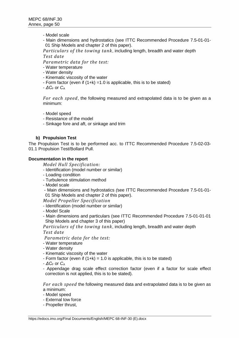
MEPC 68/INF.30 Annex, page 50
https://edocs.imo.org/Final Documents/English/MEPC 68-INF-30 (E).docx
- Model scale - Main dimensions and hydrostatics (see ITTC Recommended Procedure 7.5-01-01-01 Ship Models and chapter 2 of this paper).
Particulars of the towing tank, including length, breadth and water depth
Test date Parametric data for the test: - Water temperature - Water density - Kinematic viscosity of the water - Form factor (even if (1+k) =1.0 is applicable, this is to be stated) - ΔCF or CA
For each speed, the following measured and extrapolated data is to be given as a minimum: - Model speed - Resistance of the model - Sinkage fore and aft, or sinkage and trim
b) Propulsion Test
The Propulsion Test is to be performed acc. to ITTC Recommended Procedure 7.5-02-03-01.1 Propulsion Test/Bollard Pull. Documentation in the report
Model Hull Specification: - Identification (model number or similar) - Loading condition - Turbulence stimulation method - Model scale - Main dimensions and hydrostatics (see ITTC Recommended Procedure 7.5-01-01-01 Ship Models and chapter 2 of this paper).
Model Propeller Specification - Identification (model number or similar) - Model Scale - Main dimensions and particulars (see ITTC Recommended Procedure 7.5-01-01-01 Ship Models and chapter 3 of this paper)
Particulars of the towing tank, including length, breadth and water depth
Test date Parametric data for the test: - Water temperature - Water density - Kinematic viscosity of the water - Form factor (even if (1+k) = 1.0 is applicable, this is to be stated) - ΔCF or CA - Appendage drag scale effect correction factor (even if a factor for scale effect correction is not applied, this is to be stated).
For each speed the following measured data and extrapolated data is to be given as a minimum: - Model speed - External tow force - Propeller thrust,

MEPC 68/INF.30 Annex, page 51
https://edocs.imo.org/Final Documents/English/MEPC 68-INF-30 (E).docxhttps://edocs.imo.org/Final Documents/English/MEPC 68-INF-30 (E).docx
- Propeller torque - Rate of revolutions. - Sinkage fore and aft, or sinkage and trim - The extrapolated values are also to contain the resulting delivered power PD.
c) Propeller Open Water Test
In many cases the Propeller Open Water Characteristics of a stock propeller will be available and the Propeller Open Water Test need not be repeated for the particular project. A documentation of the Open Water Characteristics (Open Water Diagram) will suffice. In case of a final propeller or where the Propeller Open Water Characteristics is not available the Propeller Open Water Test is to be performed acc. to ITTC Recommended Procedure 7.5-02-03-02.1 Open Water Test. Documentation in the report
Model Propeller Specification: - Identification (model number or similar) - Model scale - Main dimensions and particulars (see recommendations of ITTC Recommended Procedure 7.5-01-01-01 Ship Models and chapter 3 of this paper)
- Immersion of centreline of propeller shaft in the case of towing tank
Particulars of the towing tank or cavitation tunnel, including length, breadth and water depth or test section length, breadth and height.
Test date Parametric data for the test: - Water temperature - Water density - Kinematic viscosity of the water - Reynolds Number (based on propeller blade chord at 0.7R)
For each speed the following data is to be given as a minimum: - Speed - Thrust of the propeller - Torque of the propeller - Rate of revolution - Force of nozzle in the direction of the propeller shaft (in case of ducted propeller)
Propeller Open Water Diagram

MEPC 68/INF.30 Annex, page 52
https://edocs.imo.org/Final Documents/English/MEPC 68-INF-30 (E).docx
4. Speed Trial Prediction The principal steps of the Speed Trial Prediction Calculation are given in ITTC Recommended Procedure 7.5 - 02 - 03 -1.4 ITTC 1978 Trial Prediction Method (in its latest reviewed version of 2011). The main issue of a speed trial prediction is to get the loading of the propeller correct and also to assume the correct full scale wake. The right loading of the propeller can be achieved by increasing the friction deduction by the added resistance (e.g. wind resistance etc.) and run the self-propulsion test already at the right load or it can be achieved by calculation as given in Procedure 7.5-02-03-1.4. A wake correction is always necessary for single screw ships. For twin screw ships it can be neglected unless the stern shape is of twin hull type or other special shape. The following scheme indicates the main components of a speed trial prediction. It it to be based on a Resistance Test, a Propulsion Test and an Open Water Characteristics of the used model propeller during the tests and the Propeller Open Water Characteristics of the final propeller. Documentation
Model Hull Specification: - Identification (model number or similar) - Loading condition - Turbulence stimulation method - Model scale - Main dimensions and hydrostatics (see ITTC Recommended Procedure 7.5-01-01-01 Ship Models and chapter 2 of this paper).
Model Propeller Specification - Main dimensions and particulars (see ITTC Recommended Procedure 7.5-01-01-01 Ship Models and chapter 3 of this paper)
Particulars of the towing tank, including length, breadth and water depth Resistance Test Identification (Test No. or similar) Propulsion Test Identification (Test No. or similar) Open Water Characteristics of the model propeller Open Water Characteristics of ship propeller Ship Specification: - Projected wind area - Wind resistance coefficient - Assumed BF - CP and Cn
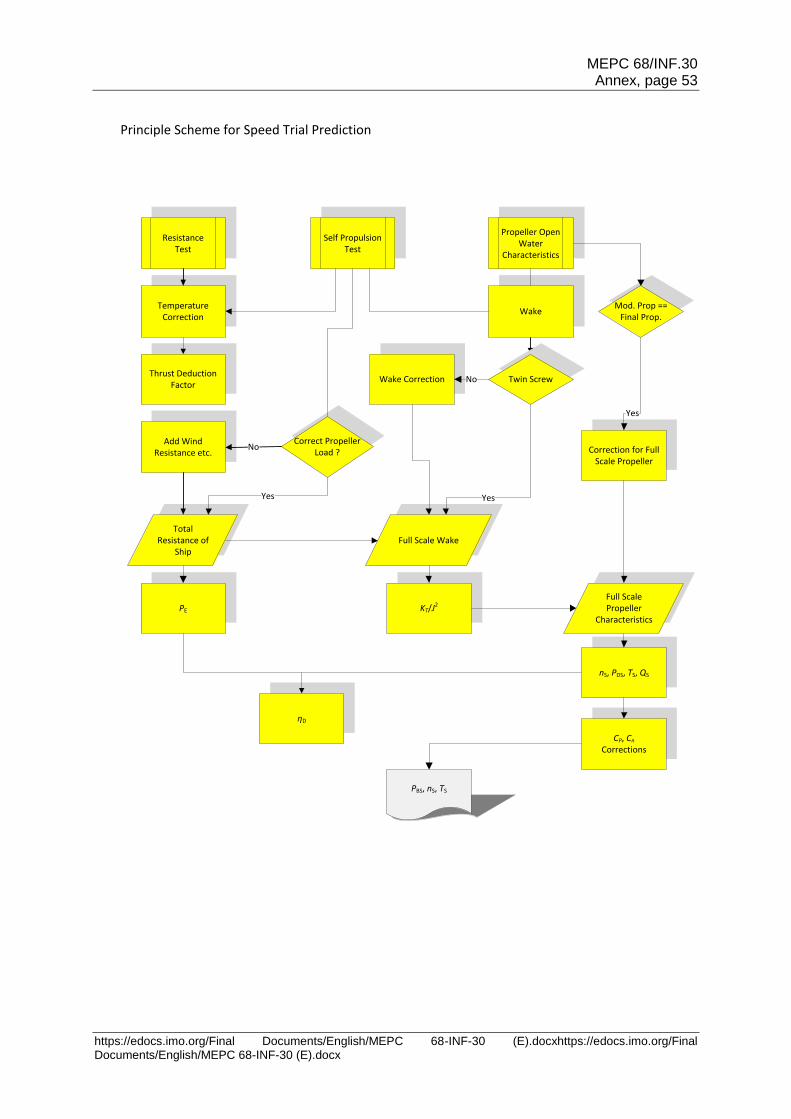
MEPC 68/INF.30 Annex, page 53
https://edocs.imo.org/Final Documents/English/MEPC 68-INF-30 (E).docxhttps://edocs.imo.org/Final Documents/English/MEPC 68-INF-30 (E).docx
Resistance Test
Self Propulsion Test
Propeller Open Water
Characteristics
Full Scale Wake
Temperature Correction
Wake
Correct Propeller Load ?
Add Wind Resistance etc.
Total Resistance of
Ship
PBS, nS, TS
CP, Cn
Corrections
No
Thrust Deduction Factor
Full Scale Propeller
Characteristics
Principle Scheme for Speed Trial Prediction
Twin ScrewWake Correction
Yes
No
Yes
Mod. Prop == Final Prop.
Correction for Full Scale Propeller
KT/J2
nS, PDS, TS, QS
PE
ηD
Yes

MEPC 68/INF.30 Annex, page 54
https://edocs.imo.org/Final Documents/English/MEPC 68-INF-30 (E).docx
For each speed the following calculated data is to be given as a minimum: - Ship speed - Model wake coefficient - Ship wake coefficient - Propeller thrust on ship - Propeller torque on ship - Rate of revolutions on ship - Predicted power on ship (delivered power on Propeller(s) PD) - Sinkage fore and aft, or sinkage and trim
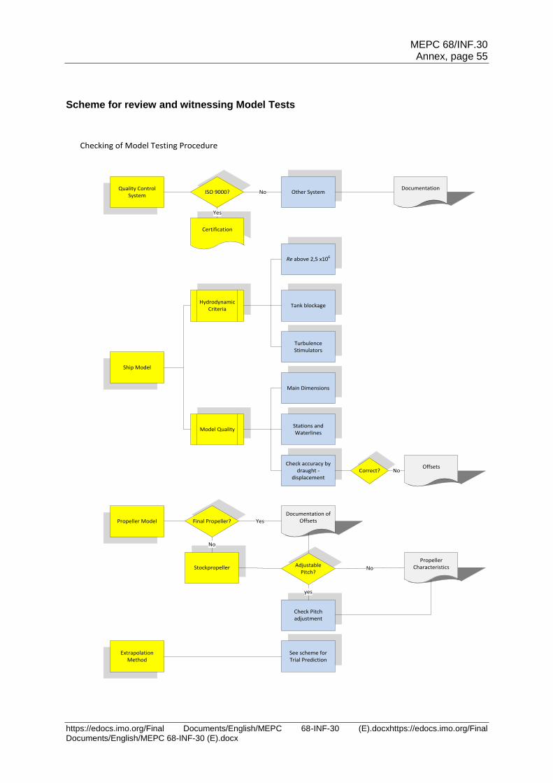
MEPC 68/INF.30 Annex, page 55
https://edocs.imo.org/Final Documents/English/MEPC 68-INF-30 (E).docxhttps://edocs.imo.org/Final Documents/English/MEPC 68-INF-30 (E).docx
Scheme for review and witnessing Model Tests
Ship Model
Extrapolation Method
Other System
Main Dimensions
Stations and Waterlines
Check accuracy by draught -
displacement
Turbulence Stimulators
Propeller Model
Check Pitch adjustment
Re above 2,5 x10⁶
Tank blockage
See scheme for Trial Prediction
Checking of Model Testing Procedure
ISO 9000?
Certification
DocumentationQuality Control System
Hydrodynamic Criteria
Model Quality
Correct?
Final Propeller?
Documentation of Offsets
No
Stockpropeller
No
Adjustable Pitch?
yes
Propeller CharacteristicsNo
Yes
Yes
No
Offsets
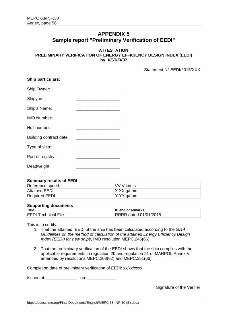
MEPC 68/INF.30 Annex, page 56
https://edocs.imo.org/Final Documents/English/MEPC 68-INF-30 (E).docx
APPENDIX 5 Sample report "Preliminary Verification of EEDI"
ATTESTATION
PRELIMINARY VERIFICATION OF ENERGY EFFICIENCY DESIGN INDEX (EEDI) by VERIFIER
Statement N° EEDI/2015/XXX
Ship particulars: Ship Owner: ___________________ Shipyard: ___________________ Ship's Name: ___________________ IMO Number: ___________________ Hull number: ___________________ Building contract date: ___________________ Type of ship: ___________________ Port of registry: ___________________ Deadweight: ___________________ Summary results of EEDI
Reference speed VV.V knots
Attained EEDI X.XX g/t.nm
Required EEDI Y.YY g/t.nm
Supporting documents Title ID and/or remarks
EEDI Technical File RRRR dated 01/01/2015
This is to certify:
1. That the attained EEDI of the ship has been calculated according to the 2014 Guidelines on the method of calculation of the attained Energy Efficiency Design Index (EEDI) for new ships, IMO resolution MEPC.245(66)
2. That the preliminary verification of the EEDI shows that the ship complies with the applicable requirements in regulation 20 and regulation 21 of MARPOL Annex VI amended by resolutions MEPC.203(62) and MEPC.251(66).
Completion date of preliminary verification of EEDI: xx/xx/xxxx Issued at: _____________ on: ____________
Signature of the Verifier

MEPC 68/INF.30 Annex, page 57
APPENDIX 6 Sample calculations of EEDI
Content
Appendix 6.1: Cruise passenger ship with diesel-electric propulsion Appendix 6.2: LNG carrier with diesel-electric propulsion Appendix 6.3: Diesel-driven LNG carrier with re-liquefaction system Appendix 6.4: LNG carrier with steam turbine propulsion
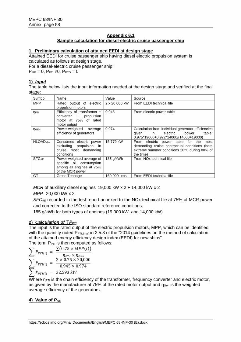
MEPC 68/INF.30 Annex, page 58
https://edocs.imo.org/Final Documents/English/MEPC 68-INF-30 (E).docx
Appendix 6.1 Sample calculation for diesel-electric cruise passenger ship
1. Preliminary calculation of attained EEDI at design stage Attained EEDI for cruise passenger ship having diesel electric propulsion system is calculated as follows at design stage. For a diesel-electric cruise passenger ship: PME = 0, PPTI ≠0, PPTO = 0 1) Input The table below lists the input information needed at the design stage and verified at the final stage:
Symbol Name Value Source
MPP Rated output of electric propulsion motors
2 x 20 000 kW From EEDI technical file
ηPTI Efficiency of transformer + converter + propulsion motor at 75% of rated motor output
0.945 From electric power table
ηGEN Power-weighted average efficiency of generators
0.974 Calculation from individual generator efficiencies given in electric power table: 0.975*19000+0.972*14000/(14000+19000)
HLOADMax Consumed electric power excluding propulsion in cruise most demanding conditions
15 779 kW From electric power table for the most demanding cruise contractual conditions (here extreme summer conditions 28°C during 80% of the time)
SFCAE Power-weighted average of specific oil consumption among all engines at 75% of the MCR power
185 g/kWh From NOx technical file
GT Gross Tonnage 160 000 ums From EEDI technical file
MCR of auxiliary diesel engines 19,000 kW x 2 + 14,000 kW x 2
MPP 20,000 kW x 2
SFCAE recorded in the test report annexed to the NOx technical file at 75% of MCR power
and corrected to the ISO standard reference conditions.
185 g/kWh for both types of engines (19,000 kW and 14,000 kW)
2) Calculation of ∑PPTI The input is the rated output of the electric propulsion motors, MPP, which can be identified with the quantity noted PPTI,Shaft in 2.5.3 of the "2014 guidelines on the method of calculation of the attained energy efficiency design index (EEDI) for new ships". The term PPTI is then computed as follows:
∑ 𝑃𝑃𝑇𝐼(𝑖) = ∑(0.75 × 𝑀𝑃𝑃(𝑖))
𝜂𝑃𝑇𝐼 × 𝜂𝐺𝑒𝑛
∑ 𝑃𝑃𝑇𝐼(𝑖) = 2 × 0.75 × 20,000
0.945 × 0.974
∑ 𝑃𝑃𝑇𝐼(𝑖) = 32,593 𝑘𝑊
Where ηPTI is the chain efficiency of the transformer, frequency converter and electric motor, as given by the manufacturer at 75% of the rated motor output and ηGen is the weighted average efficiency of the generators. 4) Value of PAE
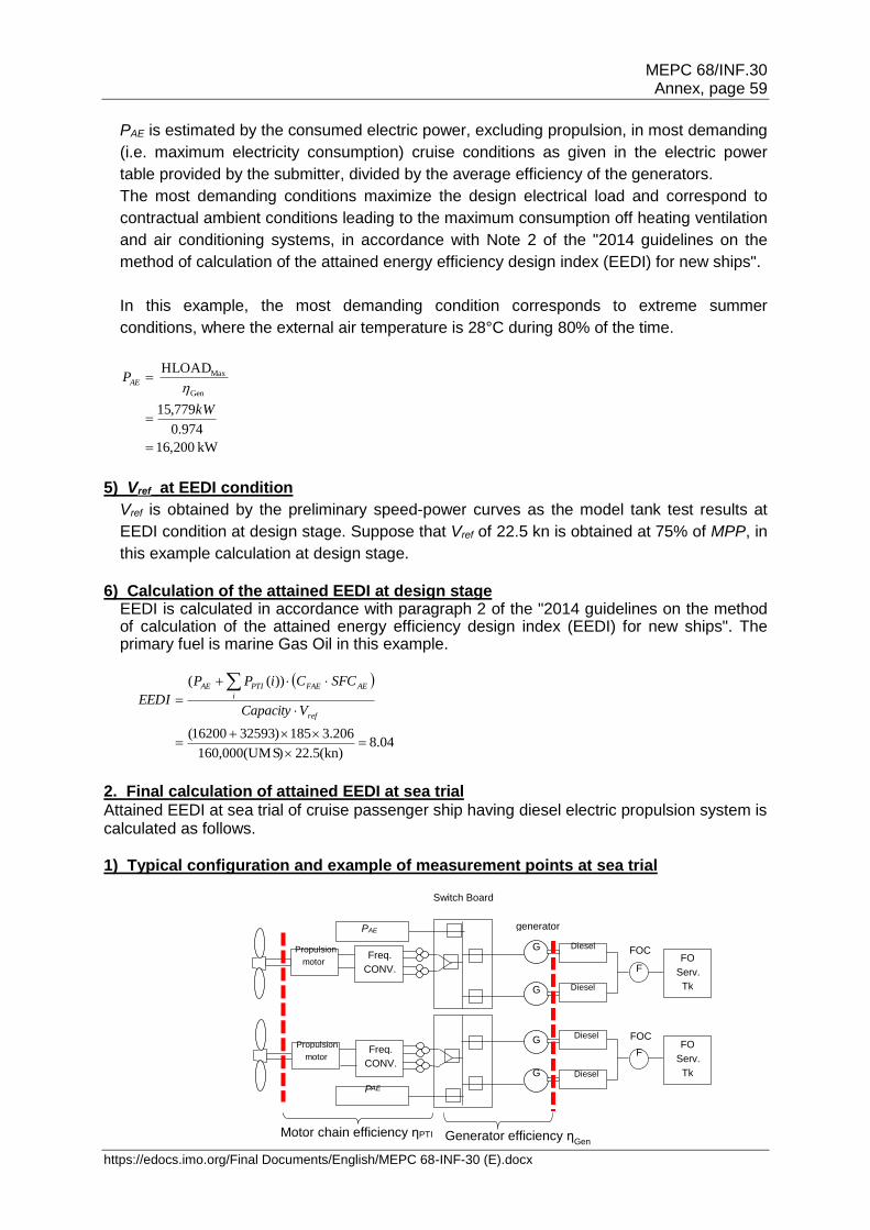
MEPC 68/INF.30 Annex, page 59
https://edocs.imo.org/Final Documents/English/MEPC 68-INF-30 (E).docx
PAE is estimated by the consumed electric power, excluding propulsion, in most demanding
(i.e. maximum electricity consumption) cruise conditions as given in the electric power
table provided by the submitter, divided by the average efficiency of the generators.
The most demanding conditions maximize the design electrical load and correspond to
contractual ambient conditions leading to the maximum consumption off heating ventilation
and air conditioning systems, in accordance with Note 2 of the "2014 guidelines on the
method of calculation of the attained energy efficiency design index (EEDI) for new ships".
In this example, the most demanding condition corresponds to extreme summer
conditions, where the external air temperature is 28°C during 80% of the time.
kW 200,61
974.0
779,15
HLOAD
Gen
Max
kW
PAE
5) Vref at EEDI condition
Vref is obtained by the preliminary speed-power curves as the model tank test results at
EEDI condition at design stage. Suppose that Vref of 22.5 kn is obtained at 75% of MPP, in
this example calculation at design stage.
6) Calculation of the attained EEDI at design stage
EEDI is calculated in accordance with paragraph 2 of the "2014 guidelines on the method of calculation of the attained energy efficiency design index (EEDI) for new ships". The primary fuel is marine Gas Oil in this example.
04.8(kn)5.22)60,000(UMS1
206.3185)3259316200(
))((
ref
AEFAE
i
PTIAE
VCapacity
SFCCiPP
EEDI
2. Final calculation of attained EEDI at sea trial Attained EEDI at sea trial of cruise passenger ship having diesel electric propulsion system is calculated as follows. 1) Typical configuration and example of measurement points at sea trial
Switch Board
Propulsion motor
Freq.
CONV.
PAE
G
G
Diesel
F
FO
Serv.
Tk
Freq.
CONV.
P AE
G
G
F
FO
Serv.
Tk
FOC
FOC
Diesel
Diesel
Diesel
Propulsion motor
generator
Motor chain efficiency ηPTI
Generator efficiency ηGen
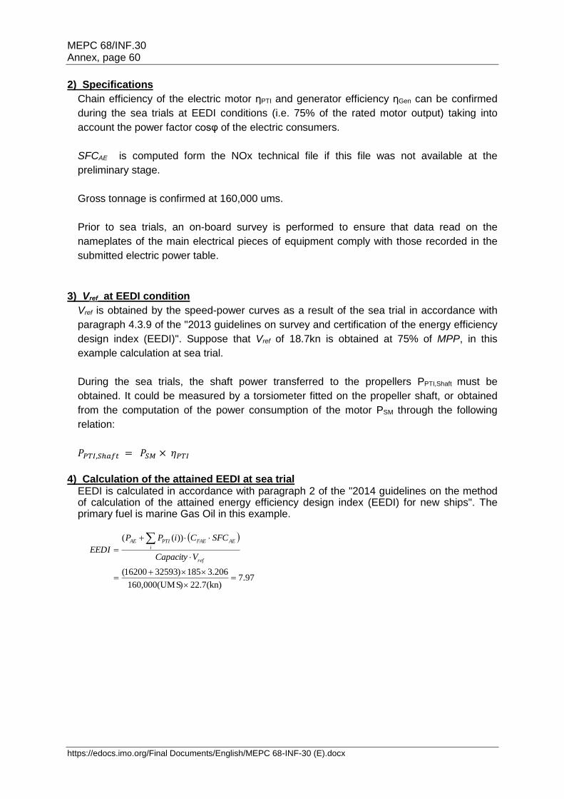
MEPC 68/INF.30 Annex, page 60
https://edocs.imo.org/Final Documents/English/MEPC 68-INF-30 (E).docx
2) Specifications
Chain efficiency of the electric motor ηPTI and generator efficiency ηGen can be confirmed
during the sea trials at EEDI conditions (i.e. 75% of the rated motor output) taking into
account the power factor cosφ of the electric consumers.
SFCAE is computed form the NOx technical file if this file was not available at the
preliminary stage.
Gross tonnage is confirmed at 160,000 ums.
Prior to sea trials, an on-board survey is performed to ensure that data read on the
nameplates of the main electrical pieces of equipment comply with those recorded in the
submitted electric power table.
3) Vref at EEDI condition
Vref is obtained by the speed-power curves as a result of the sea trial in accordance with
paragraph 4.3.9 of the "2013 guidelines on survey and certification of the energy efficiency
design index (EEDI)". Suppose that Vref of 18.7kn is obtained at 75% of MPP, in this
example calculation at sea trial.
During the sea trials, the shaft power transferred to the propellers PPTI,Shaft must be
obtained. It could be measured by a torsiometer fitted on the propeller shaft, or obtained
from the computation of the power consumption of the motor PSM through the following
relation:
𝑃𝑃𝑇𝐼,𝑆ℎ𝑎𝑓𝑡 = 𝑃𝑆𝑀 × 𝜂𝑃𝑇𝐼
4) Calculation of the attained EEDI at sea trial EEDI is calculated in accordance with paragraph 2 of the "2014 guidelines on the method of calculation of the attained energy efficiency design index (EEDI) for new ships". The primary fuel is marine Gas Oil in this example.
97.7(kn)7.22)60,000(UMS1
206.3185)3259316200(
))((
ref
AEFAE
i
PTIAE
VCapacity
SFCCiPP
EEDI
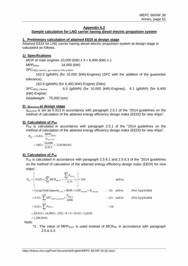
MEPC 68/INF.30 Annex, page 61
https://edocs.imo.org/Final Documents/English/MEPC 68-INF-30 (E).docx
Appendix 6.2 Sample calculation for LNG carrier having diesel electric propulsion system
1. Preliminary calculation of attained EEDI at design stage Attained EEDI for LNG carrier having diesel electric propulsion system at design stage is calculated as follows. 1) Specifications
MCR of main engines 10,000 (kW) x 3 + 6,400 (kW) x 1
MPPMotor 24,000 (kW)
SFCME(i)_electric, gas mode at 75% of MCR
162.0 (g/kWh) (for 10,000 (kW)-Engines) (SFC with the addition of the guarantee
tolerance),
162.6 (g/kWh) (for 6,400 (kW)-Engine) (Ditto)
SFCME(i)_Pilotfuel 6.0 (g/kWh) (for 10,000 (kW)-Engines), 6.1 (g/kWh) (for 6,400
(kW)-Engine)
Deadweight 75,000 (ton)
2) ηelectrical at design stage ηelectrical is set as 0.913 in accordance with paragraph 2.5.1 of the "2014 guidelines on the method of calculation of the attained energy efficiency design index (EEDI) for new ships".
3) Calculation of PME
PME is calculated in accordance with paragraph 2.5.1 of the "2014 guidelines on the method of calculation of the attained energy efficiency design index (EEDI) for new ships".
(kW)81821913.0
00024830
83.0
,,
.
MPPP
electrical
MotorME
4) Calculation of PAE
PAE is calculated in accordance with paragraph 2.5.6.1 and 2.5.6.3 of the "2014 guidelines
on the method of calculation of the attained energy efficiency design index (EEDI) for new
ships".
(kW) 1,286
818,2102.000250000,24025.0
)3( 02.0
)Applicable(Not and/or; )2( 1000
0.33
)Applicable(Not and/or; )1(
and/or; 250)75.0
(025.0
1
)(
1
)(
),(
1
)(
1
)(
nME
i
iME
nME
i
iME
gasmodeiME
reliquefyreliquefyLNG
nPTI
i
iPTInME
i
iMEAE
P
PSFC
RCOPBORapacityCargoTankC
P
MCRP
Note:
*1: The value of MPPMotor is used instead of MCRME in accordance with paragraph
2.5.6.3.3.
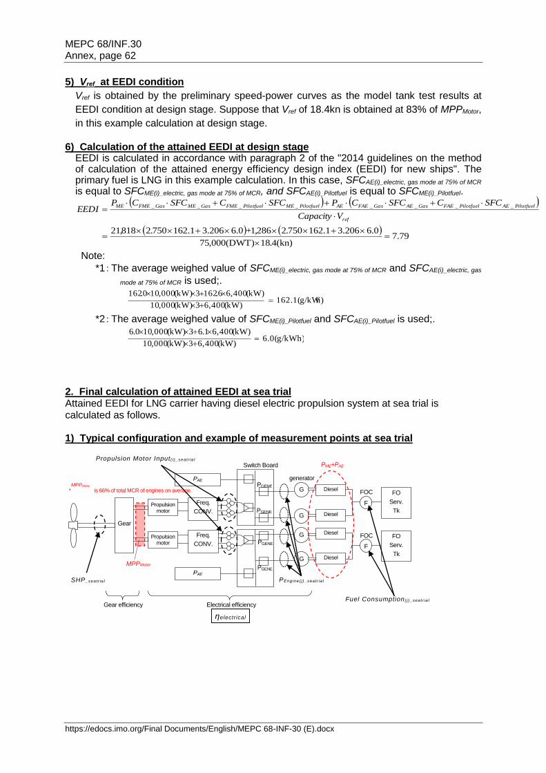
MEPC 68/INF.30 Annex, page 62
https://edocs.imo.org/Final Documents/English/MEPC 68-INF-30 (E).docx
5) Vref at EEDI condition
Vref is obtained by the preliminary speed-power curves as the model tank test results at
EEDI condition at design stage. Suppose that Vref of 18.4kn is obtained at 83% of MPPMotor,
in this example calculation at design stage.
6) Calculation of the attained EEDI at design stage
EEDI is calculated in accordance with paragraph 2 of the "2014 guidelines on the method of calculation of the attained energy efficiency design index (EEDI) for new ships". The primary fuel is LNG in this example calculation. In this case, SFCAE(i)_electric, gas mode at 75% of MCR is equal to SFCME(i)_electric, gas mode at 75% of MCR, and SFCAE(i)_Pilotfuel is equal to SFCME(i)_Pilotfuel.
79.7
(kn)418(DWT)000,75
0.6206.31.162750228610.6206.31.162750281821
________
.
.,+.,
VCapacity
SFCCSFCCPSFCCSFCCPEEDI
ref
PilotfuelAEPilotfuelFAEGasAEGasFAEAEPilotfuelMEPilotfuelFMEGasMEGasFMEME
Note:
*1: The average weighed value of SFCME(i)_electric, gas mode at 75% of MCR and SFCAE(i)_electric, gas
mode at 75% of MCR is used;.
h)162.1(g/kW(kW)400,63(kW)000,10
(kW)400,66.1623(kW)000,100.162
*2: The average weighed value of SFCME(i)_Pilotfuel and SFCAE(i)_Pilotfuel is used;.
6.0(g/kWh)(kW)400,63(kW)000,10
(kW)400,61.63(kW)000,100.6
2. Final calculation of attained EEDI at sea trial Attained EEDI for LNG carrier having diesel electric propulsion system at sea trial is calculated as follows. 1) Typical configuration and example of measurement points at sea trial
PEng ine( j)_seat r ia l
Switch Board
Propulsion motor
Gear
Freq.
CONV.
PAE
G
G
Diesel
engine F
FO
Serv.
Tk
Freq.
CONV.
PAE
G
G
F
FO
Serv.
Tk
PGENE
PGENE
PGENE
PGENE
FOC
FOC
Diesel
engine
Diesel
engine
Diesel
engine
Propulsion motor
generator
Electrical efficiency Gear efficiency
*MPPshaft is 66% of total MCR of engines on average.
MPPshaft
PME+PAE
ηelectrical
Fuel Consumption ( j )_seat r ia l
Propulsion Motor Input ( i)_seat r ia l
SHP_seat r ia l
MPPMotor
MPPMotor
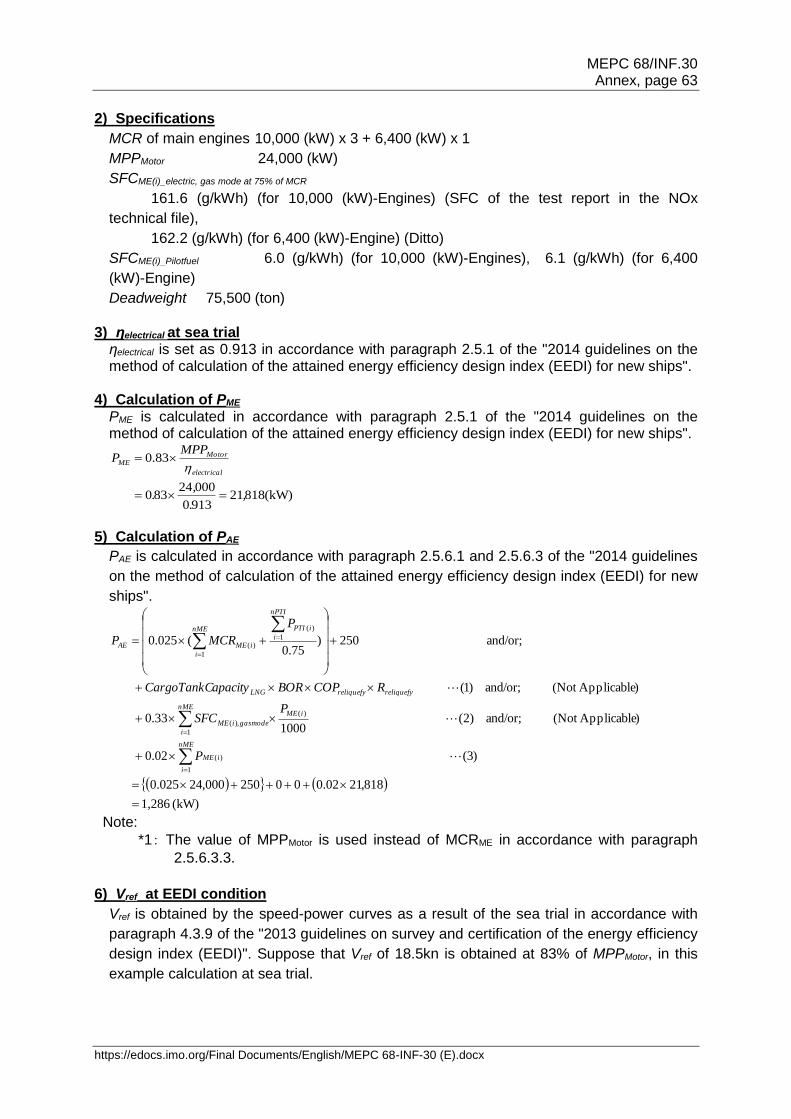
MEPC 68/INF.30 Annex, page 63
https://edocs.imo.org/Final Documents/English/MEPC 68-INF-30 (E).docx
2) Specifications
MCR of main engines 10,000 (kW) x 3 + 6,400 (kW) x 1
MPPMotor 24,000 (kW)
SFCME(i)_electric, gas mode at 75% of MCR
161.6 (g/kWh) (for 10,000 (kW)-Engines) (SFC of the test report in the NOx
technical file),
162.2 (g/kWh) (for 6,400 (kW)-Engine) (Ditto)
SFCME(i)_Pilotfuel 6.0 (g/kWh) (for 10,000 (kW)-Engines), 6.1 (g/kWh) (for 6,400
(kW)-Engine)
Deadweight 75,500 (ton)
3) ηelectrical at sea trial ηelectrical is set as 0.913 in accordance with paragraph 2.5.1 of the "2014 guidelines on the method of calculation of the attained energy efficiency design index (EEDI) for new ships".
4) Calculation of PME
PME is calculated in accordance with paragraph 2.5.1 of the "2014 guidelines on the method of calculation of the attained energy efficiency design index (EEDI) for new ships".
(kW)818219130
00024830
83.0
,.
,.
MPPP
electrical
MotorME
5) Calculation of PAE
PAE is calculated in accordance with paragraph 2.5.6.1 and 2.5.6.3 of the "2014 guidelines
on the method of calculation of the attained energy efficiency design index (EEDI) for new
ships".
(kW) 1,286
818,2102.000250000,24025.0
)3( 02.0
)Applicable(Not and/or; )2( 1000
0.33
)Applicable(Not and/or; )1(
and/or; 250)75.0
(025.0
1
)(
1
)(
),(
1
)(
1
)(
nME
i
iME
nME
i
iME
gasmodeiME
reliquefyreliquefyLNG
nPTI
i
iPTInME
i
iMEAE
P
PSFC
RCOPBORapacityCargoTankC
P
MCRP
Note:
*1: The value of MPPMotor is used instead of MCRME in accordance with paragraph
2.5.6.3.3.
6) Vref at EEDI condition
Vref is obtained by the speed-power curves as a result of the sea trial in accordance with
paragraph 4.3.9 of the "2013 guidelines on survey and certification of the energy efficiency
design index (EEDI)". Suppose that Vref of 18.5kn is obtained at 83% of MPPMotor, in this
example calculation at sea trial.

MEPC 68/INF.30 Annex, page 64
https://edocs.imo.org/Final Documents/English/MEPC 68-INF-30 (E).docx
7) Calculation of the attained EEDI at sea trial EEDI is calculated in accordance with paragraph 2 of the "2014 guidelines on the method of calculation of the attained energy efficiency design index (EEDI) for new ships". The primary fuel is LNG in this example calculation. In this case, SFCAE(i)_electric, gas mode at 75% of MCR is equal to SFCME(i)_electric, gas mode at 75% of MCR, and SFCAE(i)_Pilotfuel is equal to SFCME(i)_Pilotfuel.
67.7
(kn)518(DWT)500,75
0.6206.37161750228610.6206.37161750281821
________
.
..,+..,
VCapacity
SFCCSFCCPSFCCSFCCPEEDI
ref
PilotfuelAEPilotfuelFAEGasAEGasFAEAEPilotfuelMEPilotfuelFMEGasMEGasFMEME
Note:
*1: The average weighed value of SFCME(i)_electric, gas mode at 75% of MCR and SFCAE(i)_electric, gas
mode at 75% of MCR is used;.
h)161.7(g/kW(kW)400,63(kW)000,10
(kW)400,62.1623(kW)000,106.161
*2: The average weighed value of SFCME(i)_Pilotfuel and SFCAE(i)_Pilotfuel is used;.
6.0(g/kWh)(kW)400,63(kW)000,10
(kW)400,61.63(kW)000,100.6
MEPC 68/INF.30 Annex, page 65
https://edocs.imo.org/Final Documents/English/MEPC 68-INF-30 (E).docx
Appendix 6.3 Sample calculation for LNG carrier having diesel driven with re-liquefaction system
1. Preliminary calculation of attained EEDI at design stage Attained EEDI for LNG carrier having diesel driven with re-liquefaction system at design stage is calculated as follows. 1) Specifications
MCR ME(i) 18,660 x 2 (kW) = 37,320 (kW)
SFCME(i)_at 75% of MCR 165.0 (g/kWh)
SFCAE(i)_at 50% of MCR 198.0 (g/kWh)
CargoTankCapacityLNG 211,900 (m3)
BOR 0.15 (%/day)
COPcooling 0.166
COPreliquefy 15.142
142.15(sec)3600)(24
)/(511)/(425 3
cooling
reliquefyCOPh
kgkJmkgCOP
Rreliquefy 1
Deadweight 109,000 (ton)
2) Calculation of PME
PME is calculated in accordance with paragraph 2.5.1 of the "2014 guidelines on the method of calculation of the attained energy efficiency design index (EEDI) for new ships".
(kW)99027660,18660,18750
75.0 )()(
,.
MCRP iMEiME
3) Calculation of PAE
PAE is calculated in accordance with paragraph 2.5.6.1 and 2.5.6.3 of the "2014 guidelines on
the method of calculation of the attained energy efficiency design index (EEDI) for new
ships".
PAE = 0.025 x Σ0.0ME(i) + 250 + CargoTankCaipacityLNG x BOR x COPreliquefy x Rreliquefy = 0.025 x 37,320 +250 + 211,900 x 0.15/100 x 15.142 x 1 = 5,996 (kW)
4) Vref at EEDI condition
Vref is obtained by the preliminary speed-power curves as the model tank test results at EEDI
condition at design stage.
Suppose that Vref of 19.7kn is obtained at 75% of MCRME(i), in this example calculation at
design stage.
5) Calculation of the attained EEDI on design stage
EEDI is calculated in accordance with paragraph 2 of the "2014 guidelines on the method of
calculation of the attained energy efficiency design index (EEDI) for new ships".
MEPC 68/INF.30 Annex, page 66
https://edocs.imo.org/Final Documents/English/MEPC 68-INF-30 (E).docx
668.8(kn)719(DWT)000,109
0.198206.3996,50.1652063990,27
.
+.
VCapacity
SFCCPSFCCPEEDI
ref
AEFAEAEMEFMEME
2. Final calculation of attained EEDI at sea trial Attained EEDI for LNG carrier having diesel driven with re-liquefaction system at sea trial is calculated as follows.
1) Specifications
MCR ME(i) 18,660 x 2 (kW) = 37,320 (kW)
SFCME(i)_at 75% of MCR 165.5 (g/kWh)
SFCAE(i)_at 50% of MCR 198.5 (g/kWh)
CargoTankCapacityLNG 211,900 (m3)
BOR 0.15 (%/day)
COPcooling 0.166
COPreliquefy 15.142
142.15(sec)3600)(24
)/(511)/(425 3
cooling
reliquefyCOPh
kgkJmkgCOP
Rreliquefy 1
Deadweight 109,255 (ton)
SFCME(i)_at 75% of MCR and SFCAE(i)_at 50% of MCR are in accordance with paragraph 2.7.1 of
the "2014 guidelines on the method of calculation of the attained energy efficiency design
index (EEDI) for new ships".
Deadweight is in accordance with paragraph 4.3.10 of the "2013 guidelines on survey and
certification of the energy efficiency design index (EEDI)".
2) Measured values at sea trial
Relation between SHPseatrial and Ship's speed shall be measured and verified at sea trial.
3) Calculation of PME
PME is calculated in accordance with paragraph 2.5.1 of the "2014 guidelines on the method of calculation of the attained energy efficiency design index (EEDI) for new ships".
(kW)99027660,18660,18750
75.0 )()(
,.
MCRP iMEiME
4) Calculation of PAE
PAE is calculated in accordance with paragraph 2.5.6.3 of the "2014 guidelines on the method
of calculation of the attained energy efficiency design index (EEDI) for new ships".
PAE = 0.025 x Σ0.0ME(i) + 250 + CargoTankCaipacityLNG x BOR x COPreliquefy x Rreliquefy = 0.025 x 37,320 +250 + 211,900 x 0.15/100 x 15.142 x 1 = 5,996 (kW)
MEPC 68/INF.30 Annex, page 67
https://edocs.imo.org/Final Documents/English/MEPC 68-INF-30 (E).docx
5) Vref at EEDI condition
Vref is obtained by the speed-power curves as a result of the sea trial in accordance with
paragraph 4.3.9 of the"2013 guidelines on survey and certification of the energy efficiency
design index (EEDI)".
Suppose that Vref of 19.8kn is obtained at 75% of MCRME(i), in this example calculation at
sea trial.
6) Calculation of the attained EEDI at sea trial
EEDI is calculated in accordance with paragraph 2 of the "2014 guidelines on the method of
calculation of the attained energy efficiency design index (EEDI) for new ships".
629.8(kn)819(DWT)255,109
5.198206.3996,55.1652063990,27
.
+.
VCapacity
SFCCPSFCCPEEDI
ref
AEFAEAEMEFMEME
MEPC 68/INF.30 Annex, page 68
https://edocs.imo.org/Final Documents/English/MEPC 68-INF-30 (E).docx
Appendix 6.4 Sample calculation for LNG carrier having steam turbine propulsion system
1. Preliminary calculation of attained EEDI at design stage Attained EEDI for LNG carrier having steam turbine propulsion system at design stage is calculated as follows. 1) Specifications
MCRSteam turbine 25,000 (kW)
SFCSteam turbine 241.0 (g/kWh)
Deadweight 75,000 (ton)
2) Calculation of PME
PME is calculated in accordance with paragraph 2.5.1 of the"2014 guidelines on the method of calculation of the attained energy efficiency design index (EEDI) for new ships".
(kW)75020000,25830
83.0
,.
MCRP neSteamTurbiME
3) Calculation of PAE
PAE is treated as 0(zero) because electric load (Pgenerator_seatrial) is supposed to be included in
SFCSteamTurbine, in accordance with paragraph 2.5.6.3 and 2.7.2.1 of the "2014 guidelines on
the method of calculation of the attained energy efficiency design index (EEDI) for new
ships".
PAE = 0
4) Vref at EEDI condition
Vref is obtained by the preliminary speed-power curves as the model tank test results at EEDI
condition at design stage.
Suppose that Vref of 18.7kn is obtained at 83% of MCRSteamTurbine, in this example
calculation at design stage.
5) Calculation of the attained EEDI on design stage
EEDI is calculated in accordance with paragraph 2 of the "2014 guidelines on the method of
calculation of the attained energy efficiency design index (EEDI) for new ships".
The primary fuel is LNG in this example calculation.
81.9(kn)718(DWT)000,75
00.2417502750,20
.
+.
VCapacity
SFCCPSFCCPEEDI
ref
AEFAEAEMEFMEME
MEPC 68/INF.30 Annex, page 69
https://edocs.imo.org/Final Documents/English/MEPC 68-INF-30 (E).docx
2. Final calculation of attained EEDI at sea trial Attained EEDI for LNG carrier having steam turbine propulsion system at sea trial is calculated as follows. 1) Typical configuration and example of measurement points at sea trial
In addition to the above, in order to correct measured Fuel Consumption to the design
conditions corresponding to the SNAME condition, inlet air temperature, sea water
temperature, steam temperature, steam pressure, etc. are measured, as appropriate.
PAE is treated as 0(zero) because electric load (Pgenerator_seatrial) is supposed to be included in
SFCSteamTurbine, in accordance with paragraph 2.5.6.3 and 2.7.2.1 of the "2014 guidelines on
the method of calculation of the attained energy efficiency design index (EEDI) for new
ships".
2) Specifications
MCRSteam turbine 25,000 (kW)
SFCSteam turbine 241.0 (g/kWh)
Deadweight 75,000 (ton)
3) Measured values at sea trial
Pgenerator_seatrial 980 (kW)
SHPseatrial 21,520 (kW)
Fuel Consumption_seatrial 5.95 x 10⁶ (g/hour)
Each Fuel Consumption(j)_seatrial should be corrected in accordance with paragraph 2.7.2
of the "2014 guidelines on the method of calculation of the attained energy efficiency
design index (EEDI) for new ships".
Coefficient of flow meter 1.0010
Steam temperature 500 degree Celsius
Steam pressure 5.85 (MPaG)
Condenser vacuum 725 (mmHg)
Dist. water production 28.5 (t/day)
Inlet air temperature of FAN 45 degree Celsius
Lower calorific value of fuel used at sea trial 42,030 (kJ/kg)
Pgenerator_seatrial
Condenser Vacuum,
Volume of Water
Steam Temperature
and Pressure
Fuel Consumption_seatrial
SHP_seatr ial MCRSteamTurbine
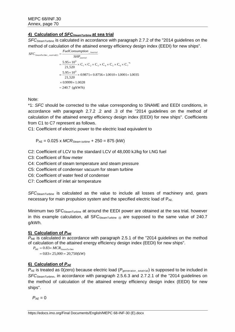
MEPC 68/INF.30 Annex, page 70
https://edocs.imo.org/Final Documents/English/MEPC 68-INF-30 (E).docx
4) Calculation of SFCSteamTurbine at sea trial
SFCSteamTurbine is calculated in accordance with paragraph 2.7.2 of the "2014 guidelines on the
method of calculation of the attained energy efficiency design index (EEDI) for new ships".
g/kW/h)( 7.240
0028.199990
0035100011001018756.09871021,520
105.95
CCCCCCC21,520
105.95
6
1*
7654321
6
_
)(_
.
....
SHP
ptionFuelConsumSFC
seatrial
Seatrial
iseatrialneSteamTurbi
Note:
*1: SFC should be corrected to the value corresponding to SNAME and EEDI conditions, in
accordance with paragraph 2.7.2 .2 and .3 of the "2014 guidelines on the method of
calculation of the attained energy efficiency design index (EEDI) for new ships". Coefficients
from C1 to C7 represent as follows.
C1: Coefficient of electric power to the electric load equivalent to
PAE = 0.025 x MCRSteam turbine + 250 = 875 (kW)
C2: Coefficient of LCV to the standard LCV of 48,000 kJ/kg for LNG fuel
C3: Coefficient of flow meter
C4: Coefficient of steam temperature and steam pressure
C5: Coefficient of condenser vacuum for steam turbine
C6: Coefficient of water feed of condenser
C7: Coefficient of inlet air temperature
SFCSteamTurbine is calculated as the value to include all losses of machinery and, gears
necessary for main propulsion system and the specified electric load of PAE.
Minimum two SFCSteamTurbine at around the EEDI power are obtained at the sea trial. however
in this example calculation, all SFCSteamTurbine (i) are supposed to the same value of 240.7
g/kWh.
5) Calculation of PME
PME is calculated in accordance with paragraph 2.5.1 of the "2014 guidelines on the method of calculation of the attained energy efficiency design index (EEDI) for new ships".
(kW)75020000,25830
83.0
,.
MCRP neSteamTurbiME
6) Calculation of PAE
PAE is treated as 0(zero) because electric load (Pgenerator_seatrial) is supposed to be included in
SFCSteamTurbine, in accordance with paragraph 2.5.6.3 and 2.7.2.1 of the "2014 guidelines on
the method of calculation of the attained energy efficiency design index (EEDI) for new
ships".
PAE = 0
MEPC 68/INF.30 Annex, page 71
https://edocs.imo.org/Final Documents/English/MEPC 68-INF-30 (E).docx
7) Vref at EEDI condition
Vref is obtained by the speed-power curves as a result of the sea trial in accordance with
paragraph 4.3.9 of the "2013 guidelines on survey and certification of the energy efficiency
design index (EEDI)".
Suppose that Vref of 18.8kn is obtained at 83% of MCRSteamTurbine, in this example
calculation at sea trial.
8) Calculation of the attained EEDI at sea trial
EEDI is calculated in accordance with paragraph 2 of the "2014 guidelines on the method of
calculation of the attained energy efficiency design index (EEDI) for new ships".
The primary fuel is LNG in this example calculation.
74.9(kn)818(DWT)000,75
07.2407502750,20
.
+.
VCapacity
SFCCPSFCCPEEDI
ref
AEFAEAEMEFMEME
___________
Top Related