


Languages
Pages
Legal

2008 Standard for
Performance Rating
of Unitary Air-Conditioning& Air-Source Heat PumpEquipment
AHRI Standard 210/240(formerly ARI Standard 210/240)
Price $20.00 (M) $40.00 (NM) ©Copyright 2008, by Air-Conditioning, Heating and Refrigeration InstitutePrinted in U.S.A. Registered United States Patent and Trademark Office
IMPORTANT
SAFETY DISCLAIMERAHRI does not set safety standards and does not certify or guarantee the safety of any products, components orsystems designed, tested, rated, installed or operated in accordance with this standard/guideline. It is stronglyrecommended that products be designed, constructed, assembled, installed and operated in accordance withnationally recognized safety standards and code requirements appropriate for products covered by thisstandard/guideline.
AHRI uses its best efforts to develop standards/guidelines employing state-of-the-art and accepted industrypractices. AHRI does not certify or guarantee that any tests conducted under its standards/guidelines will benon-hazardous or free from risk.
AHRI CERTIFICATION PROGRAM PROVISIONS
Scope of the Certification Program
The Certification Program includes all Unitary Air-Conditioning and Air-Source Unitary Heat Pump equipmentrated below 65,000 Btu/h [19,000 W] at AHRI Standard Rating Conditions (Cooling).
Certified Ratings
The following Certification Program ratings are verified by test:
Unitary Air-Conditioners
A. Air-cooled under 65,000 Btu/h [19,000 W]1. AHRI Standard Rating Cooling Capacity, Btu/h [W]2. Seasonal Energy Efficiency Ratio, SEER, Btu/(Wh)
B. Water-cooled and evaporative-cooled under 65,000 Btu/h [19,000 W]1. AHRI Standard Rating Cooling Capacity, Btu/h [W]2. Energy Efficiency Ratio, EER, Btu/(Wh)
Air-Source Unitary Heat Pumps
Air-cooled under 65,000 Btu/h [19,000 W]1. AHRI Standard Rating Cooling Capacity, Btu/h [W]2. Seasonal Energy Efficiency Ratio, SEER, Btu/(Wh)3. High Temperature Heating Standard Rating Capacity, Btu/h [W]4. Region IV Heating Seasonal Performance Factor, HSPF, Minimum Design Heating Requirement,
Btu/(Wh)
Conformance to the requirements of the Maximum Operating Conditions Test, Voltage Tolerance Test, Low-Temperature Operation Test (Cooling), Insulation Effectiveness Test (Cooling), and Condensate Disposal Test(Cooling), as outlined in Section 8, are also verified by test.
Note:
This standard supersedes ARI Standard 210/240-2006.
TABLE OF CONTENTS
SECTION PAGE
Section 1. Purpose.....................................................................................................................1
Section 2. Scope........................................................................................................................1
Section 3. Definitions................................................................................................................1
Section 4. Classifications ..........................................................................................................4
Section 5. Test Requirements ...................................................................................................4
Section 6. Rating Requirements................................................................................................4
Section 7. Minimum Data Requirements for Published Ratings ............................................24
Section 8. Operating Requirements ........................................................................................24
Section 9. Marking and Nameplate Data ................................................................................27
Section 10. Conformance Conditions .......................................................................................27
TABLES
Table 1. Classification of Unitary Air-Conditioners .................................................................6
Table 2. Classification of Air-Source Unitary Heat Pumps ......................................................7
Table 3. Cooling Mode Test Conditions for Units Having a Single-Speed Compressorand a Fixed-Speed Indoor Fan, a Constant Air Volume Rate Indoor Fan,or No Indoor Fan ........................................................................................................14
Table 4. Heating Mode Test Conditions for Units Having a Single-Speed Compressorand a Fixed-Speed Indoor Fan, a Constant Air Volume Rate Indoor Fan,or No Indoor Fan ........................................................................................................14
Table 5. Cooling Mode Test Conditions for Units Having a Single-Speed Compressorand a Variable Air Volume Rate Indoor Fan that Correlates with theOutdoor Dry Bulb Temperature (Section 6.1.4.3.1) .................................................15
Table 6. Heating Mode Test Conditions for Units Having a Single-Speed Compressorand a Variable Air Volume Rate Indoor Fan.............................................................16
TABLES (Cont’d)
Table 7. Cooling Mode Test Conditions for Units Having a Two-CapacityCompressor.................................................................................................................17
Table 8. Heating Mode Test Conditions for Units Having a Two-CapacityCompressor.................................................................................................................18
Table 9. Cooling Mode Test Conditions for Units Having a Variable-SpeedCompressor.................................................................................................................19
Table 10. Heating Mode Test Conditions for Units Having a Variable-SpeedCompressor.................................................................................................................20
Table 11. Minimum External Static Pressure for Ducted Systems Testedwith an Indoor Fan Installed .....................................................................................20
Table 12. Conditions for Standard Rating Tests and Operating Requirement Tests forWater-cooled and Evaporative-cooled Equipment Using ASHRAEStandard 37 .................................................................................................................21
Table 13. Conditions for Operating Requirement Tests for Air-cooled Equipment ................25
FIGURE
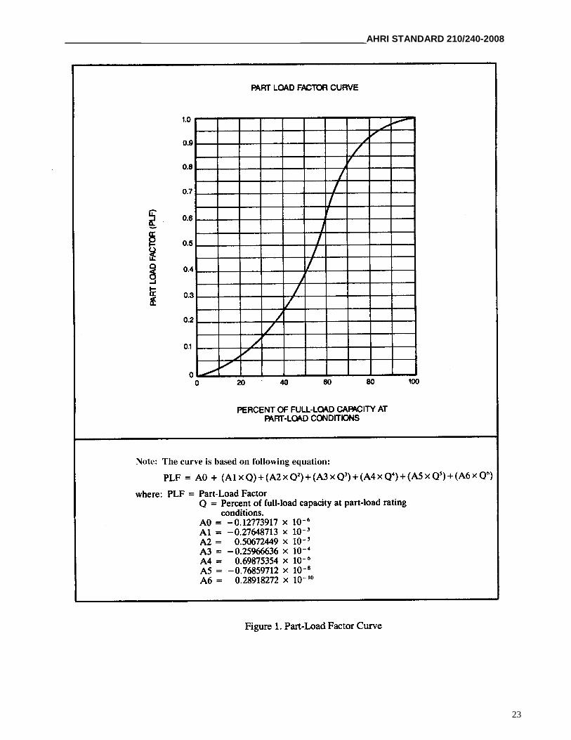
Figure 1. Part-Load Factor Curve..........................................................................................23
APPENDICES
Appendix A. References – Normative...................................................................................28
Appendix B. References – Informative.................................................................................29
Appendix C. Uniform Test Method for Measuring the Energy Consumption of CentralAir Conditioners and Heat Pumps – Normative ..............................................30
Appendix D. Prescriptive Methodology for the Cyclic Testing of Ducted Systems –Normative ......................................................................................................117
Appendix E. Example of Calculating Integrated Part-Load Values (IPLV) – Normative....122
TABLE FOR APPENDICES
Table E1. Example IPLV Calculation ............................................................................125
FIGURES FOR APPENDICES
Figure D1. Tunnel Air Enthalpy Test Method Arrangement ...........................................118
Figure D2. Loop Air Enthalpy Test Method Arrangement..............................................119
Figure D3. Calorimeter Air Enthalpy Test Method Arrangement ...................................120
Figure D4. Room Air Enthalpy Test Method Arrangement.............................................121
Figure E1. Part-Load Factor Example .............................................................................124

______________________________________________________________________________AHRI STANDARD 210/240-2008
1
PERFORMANCE RATING OF UNITARY AIR-CONDITIONING AND AIR-SOURCE HEAT
PUMP EQUIPMENT
Section 1. Purpose
1.1 Purpose. The purpose of this standard is to establish, for Unitary Air-Conditioners and Air-Source Unitary HeatPumps: definitions; classifications; test requirements; rating requirements; minimum data requirements for PublishedRatings; operating requirements; marking and nameplate data; and conformance conditions.
1.1.1 Intent. This standard is intended for the guidance of the industry, including manufacturers, engineers,installers, contractors and users.
1.1.2 Review and Amendment. This standard is subject to review and amendment as technology advances.
Section 2. Scope
2.1 Scope. This standard applies to factory-made Unitary Air-Conditioners and Air-Source Unitary Heat Pumps asdefined in Section 3.
2.1.1 Energy Source. This standard applies only to electrically operated, vapor compression refrigerationsystems.
2.2 Exclusions.
2.2.1 This standard does not apply to the rating and testing of individual assemblies, such as condensing units orcoils, for separate use.
2.2.2 This standard does not apply to heat operated air-conditioning/heat pump equipment, or to packagedterminal air-conditioners/heat pumps, or to room air-conditioners/heat pumps.
2.2.3 This standard does not apply to Unitary Air-Conditioners as defined in AHRI Standard 340/360 withcapacities of 65,000 Btu/h [19,000 W] or greater.
2.2.4 This standard does not apply to Air-Source Unitary Heat Pumps as defined in AHRI Standard 340/360 withcooling capacities of 65,000 Btu/h [19,000 W] or greater, or to water-source heat pumps, to ground water-sourceheat pumps, and to ground source closed-loop heat pumps.
2.2.5 This standard does not include water heating heat pumps.
2.2.6 This standard does not apply to rating units equipped with desuperheater/water heating devices inoperation.
Section 3. Definitions
All terms in this document shall follow the standard industry definitions in the current edition of ASHRAE Terminology ofHeating, Ventilation, Air- Conditioning and Refrigeration, unless otherwise defined in this section.
Note: Definitions for Small-duct, High-velocity Systems, Space Constrained Products, and Through-the-wall AirConditioners and Heat Pumps are taken from Title 10, Code of Federal Regulations, Part 430, Subparts 430.2 and 430.32 (c).See Appendix C for definitions that apply to the testing and calculation procedures required by Appendix C.
AHRI STANDARD 210/240-2008 _____________________ _____________
2
3.1 Air-Source Unitary Heat Pump. One or more factory-made assemblies which normally include an indoorconditioning coil(s), compressor(s), and outdoor coil(s), including means to provide a heating function. When suchequipment is provided in more than one assembly, the separated assemblies shall be designed to be used together, and therequirements of rating outlined in the standard are based upon the use of matched assemblies.
3.1.1 Functions. They shall provide the function of air heating with controlled temperature, and may include thefunctions of air-cooling, air-circulating, air-cleaning, dehumidifying or humidifying.
3.2 Degradation Coefficient (CD). The measure of the efficiency loss due to the cycling of the units as determined inAppendices C and D.
3.3 Design Heating Requirement (DHR). This is the amount of heating required to maintain a given indoor temperatureat a particular outdoor design temperature.
3.4 Energy Efficiency Ratio (EER). A ratio of the cooling capacity in Btu/h to the power input value in watts at anygiven set of Rating Conditions expressed in Btu/(Wh).
3.4.1 Standard Energy Efficiency Ratio. A ratio of the capacity to power input value obtained at Standard RatingConditions.
3.5 Heating Seasonal Performance Factor (HSPF). The total space heating required during the space heating season,expressed in Btu’s, divided by the total electrical energy consumed by the heat pump system during the same season,expressed in watt-hours.
3.6 Integrated Part-Load Value (IPLV). A single number part-load efficiency figure of merit calculated per the methoddescribed in this standard.
3.7 Published Rating. A statement of the assigned values of those performance characteristics, under stated RatingConditions, by which a unit may be chosen to fit its application. These values apply to all units of like nominal capacity andtype (identification) produced by the same manufacturer. As used herein, the term Published Rating includes the rating of allperformance characteristics shown on the unit or published in specifications, advertising, or other literature controlled by themanufacturer, at stated Rating Conditions.
3.7.1 Application Rating. A rating based on tests performed at Application Rating Conditions (other thanStandard Rating Conditions).
3.7.2 Standard Rating. A rating based on tests performed at Standard Rating Conditions.
3.8 Rating Conditions. Any set of operating conditions under which a single level of performance results and whichcauses only that level of performance to occur.
3.8.1 Standard Rating Conditions. Rating Conditions used as the basis of comparison for performancecharacteristics.
3.9 Seasonal Energy Efficiency Ratio (SEER). The total heat removed from the conditioned space during the annualcooling season, expressed in Btu’s, divided by the total electrical energy consumed by the air conditioner or heat pumpduring the same season, expressed in watt-hours.
3.10 "Shall" or "Should". "Shall" or "should" shall be interpreted as follows:
3.10.1 Shall. Where "shall" or "shall not" is used for a provision specified, that provision is mandatory ifcompliance with the standard is claimed.
3.10.2 Should. "Should" is used to indicate provisions which are not mandatory but which are desirable as goodpractice.
__________________ _______________ AHRI STANDARD 210/240-2008
3
3.11 Small-duct, High-velocity System. A heating and/or cooling product that contains a blower and indoor coilcombination that is designed for, and produces, at least 1.2 in H2O [300 Pa] of external static pressure when operated at thecertified air volume rate of 220-350 cfm [0.104 – 0.165 m3/s] per rated ton [12,000 Btu/h] of cooling. When applied in thefield, small-duct products use high-velocity room outlets (i.e., generally greater than 1,000 fpm [5 m/s]) having less than 6.0in2 [3,900 mm2] of free area.
3.12 Space Constrained Product. A central air conditioner or heat pump:
a. that has rated cooling capacities no greater than 30,000 Btu/h [8,800 W];b. that has an outdoor or indoor unit having at least two overall exterior dimensions or an overall displacement
that:1. is substantially smaller than those of other units that are:
a. currently usually installed in site built single family homes; andb. of a similar cooling, and, if a heat pump, heating capacity; and
2. if increased, would certainly result in a considerable increase in the usual cost of installation or wouldcertainly result in a significant loss in the utility of the product to the consumer; and
c. of a product type that was available for purchase in the United States as of December 1, 2000.
3.13 Standard Air. Air weighing 0.075 lb/ft3 [1.2 kg/m3] which approximates dry air at 70F [21C] and at a barometricpressure of 29.92 in Hg [101.3 kPa].
3.14 Tested Combination for Multiple-split air conditioners and heat pumps.
3.14.1 Tested combination means a multi-split system with multiple indoor coils having the following features:
3.14.2 The basic model of a system used as a tested combination shall consist of one outdoor unit, with one or morecompressors, that is matched with between 2 and 5 indoor units; for multi-split systems, each of these indoor unitsshall be designed for individual operation.
3.14.3 The indoor units shall:
3.14.3.1 Represent the highest sales model family, or another indoor model family if the highest salesmodel family does not provide sufficient capacity (see 3.14.3.2);
3.14.3.2 Together, have a nominal cooling capacity that is between 95% and 105% of the nominal coolingcapacity of the outdoor unit;
3.14.3.3 Not, individually, have a capacity that is greater than 50% of the nominal capacity of the outdoorunit;
3.14.3.4 Operate at fan speeds that are consistent with the manufacturer's specifications; and
3.14.3.5 All be subject to the same minimum external static pressure requirement (i.e., 0 in H2O [0 Pa]) fornon-ducted, see Table 2 in Appendix M to Subpart B of this part for ducted indoor units) while beingconfigurable to produce the same static pressure at the exit of each outlet plenum when manifolded as persection 2.4.1 of Appendix M to Subpart B of Part 430 – Uniform Test Method for Measuring the EnergyConsumption of Central Air Conditioners and Heat Pumps.
3.15 Through-the-wall Air Conditioner and Heat Pump. A central air conditioner or heat pump that is designed to beinstalled totally or partially within a fixed-size opening in an exterior wall, and:
a. is manufactured prior to January 23, 2010;b. is not weatherized;c. is clearly and permanently marked for installation only through an exterior wall;d. has a rated cooling capacity no greater than 30,000 Btu/h [8,800 W];e. exchanges all of its outdoor air across a single surface of the equipment cabinet; andf. has a combined outdoor air exchange area of less than 800 in2 [0.516 m2] (split systems) or less than 1,210 in2
[0.7804 m2] (single packaged systems) as measured on the surface described in 3.14.e.
AHRI STANDARD 210/240-2008 _____________________ _____________
4
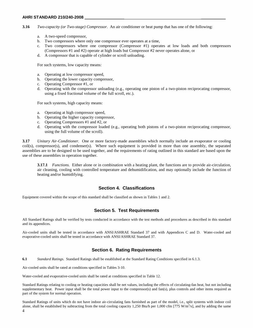
3.16 Two-capacity (or Two-stage) Compressor. An air conditioner or heat pump that has one of the following:
a. A two-speed compressor,b. Two compressors where only one compressor ever operates at a time,c. Two compressors where one compressor (Compressor #1) operates at low loads and both compressors
(Compressors #1 and #2) operate at high loads but Compressor #2 never operates alone, ord. A compressor that is capable of cylinder or scroll unloading.
For such systems, low capacity means:
a. Operating at low compressor speed,b. Operating the lower capacity compressor,c. Operating Compressor #1, ord. Operating with the compressor unloading (e.g., operating one piston of a two-piston reciprocating compressor,
using a fixed fractional volume of the full scroll, etc.).
For such systems, high capacity means:
a. Operating at high compressor speed,b. Operating the higher capacity compressor,c. Operating Compressors #1 and #2, ord. Operating with the compressor loaded (e.g., operating both pistons of a two-piston reciprocating compressor,
using the full volume of the scroll).
3.17 Unitary Air-Conditioner. One or more factory-made assemblies which normally include an evaporator or coolingcoil(s), compressor(s), and condenser(s). Where such equipment is provided in more than one assembly, the separatedassemblies are to be designed to be used together, and the requirements of rating outlined in this standard are based upon theuse of these assemblies in operation together.
3.17.1 Functions. Either alone or in combination with a heating plant, the functions are to provide air-circulation,air cleaning, cooling with controlled temperature and dehumidification, and may optionally include the function ofheating and/or humidifying.
Section 4. Classifications
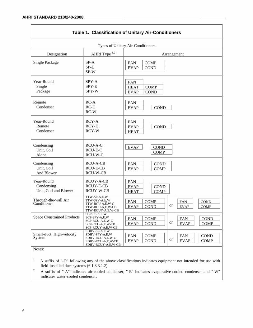
Equipment covered within the scope of this standard shall be classified as shown in Tables 1 and 2.
Section 5. Test Requirements
All Standard Ratings shall be verified by tests conducted in accordance with the test methods and procedures as described in this standardand its appendices.
Air-cooled units shall be tested in accordance with ANSI/ASHRAE Standard 37 and with Appendices C and D. Water-cooled andevaporative-cooled units shall be tested in accordance with ANSI/ASHRAE Standard 37.
Section 6. Rating Requirements
6.1 Standard Ratings. Standard Ratings shall be established at the Standard Rating Conditions specified in 6.1.3.
Air-cooled units shall be rated at conditions specified in Tables 3-10.
Water-cooled and evaporative-cooled units shall be rated at conditions specified in Table 12.
Standard Ratings relating to cooling or heating capacities shall be net values, including the effects of circulating-fan heat, but not includingsupplementary heat. Power input shall be the total power input to the compressor(s) and fan(s), plus controls and other items required aspart of the system for normal operation.
Standard Ratings of units which do not have indoor air-circulating fans furnished as part of the model, i.e., split systems with indoor coilalone, shall be established by subtracting from the total cooling capacity 1,250 Btu/h per 1,000 cfm [775 W/m3/s], and by adding the same
__________________ _______________ AHRI STANDARD 210/240-2008
5
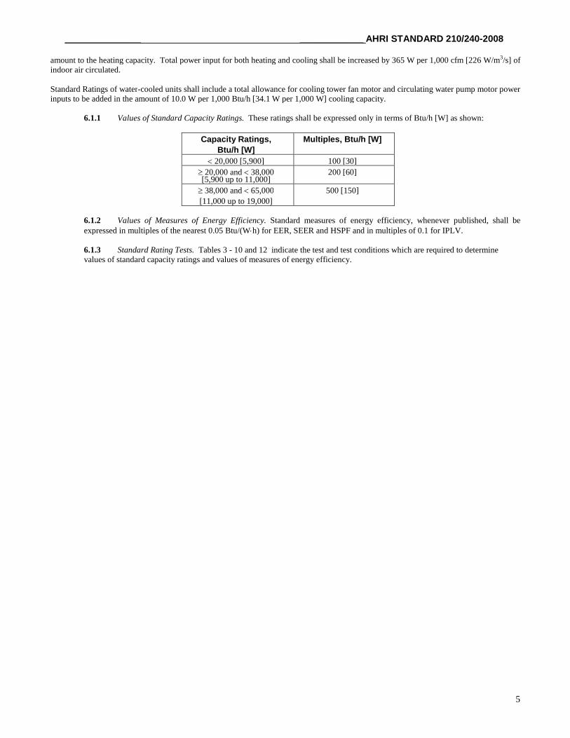
amount to the heating capacity. Total power input for both heating and cooling shall be increased by 365 W per 1,000 cfm [226 W/m3/s] ofindoor air circulated.
Standard Ratings of water-cooled units shall include a total allowance for cooling tower fan motor and circulating water pump motor powerinputs to be added in the amount of 10.0 W per 1,000 Btu/h [34.1 W per 1,000 W] cooling capacity.
6.1.1 Values of Standard Capacity Ratings. These ratings shall be expressed only in terms of Btu/h [W] as shown:
Capacity Ratings,
Btu/h [W]
Multiples, Btu/h [W]
20,000 [5,900] 100 [30]
20,000 and 38,000[5,900 up to 11,000]
200 [60]
38,000 and 65,000
[11,000 up to 19,000]
500 [150]
6.1.2 Values of Measures of Energy Efficiency. Standard measures of energy efficiency, whenever published, shall beexpressed in multiples of the nearest 0.05 Btu/(Wh) for EER, SEER and HSPF and in multiples of 0.1 for IPLV.
6.1.3 Standard Rating Tests. Tables 3 - 10 and 12 indicate the test and test conditions which are required to determinevalues of standard capacity ratings and values of measures of energy efficiency.
AHRI STANDARD 210/240-2008 _____________________ _____________
6
Table 1. Classification of Unitary Air-Conditioners
Types of Unitary Air-Conditioners
Designation AHRI Type 1,2 Arrangement
Single Package SP-ASP-ESP-W
FAN COMPEVAP COND
Year-RoundSinglePackage
SPY-ASPY-ESPY-W
FANHEAT COMPEVAP COND
RemoteCondenser
RC-ARC-ERC-W
FANEVAP COND
Year-RoundRemoteCondenser
RCY-ARCY-ERCY-W
FANEVAP CONDHEAT
CondensingUnit, CoilAlone
RCU-A-CRCU-E-CRCU-W-C
EVAP CONDCOMP
CondensingUnit, CoilAnd Blower
RCU-A-CBRCU-E-CBRCU-W-CB
FAN CONDEVAP COMP
Year-RoundCondensingUnit, Coil and Blower
RCUY-A-CBRCUY-E-CBRCUY-W-CB
FANEVAP CONDHEAT COMP
Through-the-wall AirConditioner
TTW-SP-A,E,WTTW-SPY-A,E,WTTW-RCU-A,E,W-CTTW-RCU-A,E,W-CBTTW-RCUY-A,E,W-CB
FAN COMPEVAP COND or
FAN COND
EVAP COMP
Space Constrained ProductsSCP-SP-A,E,WSCP-SPY-A,E,WSCP-RCU-A,E,W-CSCP-RCU-A,E,W-CBSCP-RCUY-A,E,W-CB
FAN COMPEVAP COND or
FAN CONDEVAP COMP
Small-duct, High-velocitySystem
SDHV-SP-A,E,WSDHV-SPY-A,E,WSDHV-RCU-A,E,W-CSDHV-RCU-A,E,W-CBSDHV-RCUY-A,E,W-CB
FAN COMPEVAP COND or
FAN CONDEVAP COMP
Notes:
1 A suffix of "-O" following any of the above classifications indicates equipment not intended for use withfield-installed duct systems (6.1.3.3.1.2).
2 A suffix of "-A" indicates air-cooled condenser, "-E" indicates evaporative-cooled condenser and "-W"indicates water-cooled condenser.
__________________ _______________ AHRI STANDARD 210/240-2008
7
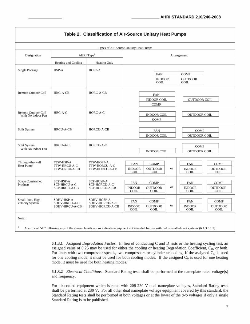
6.1.3.1 Assigned Degradation Factor. In lieu of conducting C and D tests or the heating cycling test, anassigned value of 0.25 may be used for either the cooling or heating Degradation Coefficient, CD, or both.For units with two compressor speeds, two compressors or cylinder unloading, if the assigned CD is usedfor one cooling mode, it must be used for both cooling modes. If the assigned CD is used for one heatingmode, it must be used for both heating modes.
6.1.3.2 Electrical Conditions. Standard Rating tests shall be performed at the nameplate rated voltage(s)and frequency.
For air-cooled equipment which is rated with 208-230 V dual nameplate voltages, Standard Rating testsshall be performed at 230 V. For all other dual nameplate voltage equipment covered by this standard, theStandard Rating tests shall be performed at both voltages or at the lower of the two voltages if only a singleStandard Rating is to be published.
Table 2. Classification of Air-Source Unitary Heat Pumps
Types of Air-Source Unitary Heat Pumps
Designation AHRI Type1 Arrangement
Heating and Cooling Heating Only
Single Package HSP-A HOSP-A
FAN COMP
INDOORCOIL
OUTDOORCOIL
Remote Outdoor Coil HRC-A-CB HORC-A-CBFAN
INDOOR COIL OUTDOOR COIL
COMP
Remote Outdoor CoilWith No Indoor Fan
HRC-A-C HORC-A-CINDOOR COIL OUTDOOR COIL
COMP
Split System HRCU-A-CB HORCU-A-CB FAN COMP
INDOOR COIL OUTDOOR COIL
Split SystemWith No Indoor Fan
HRCU-A-C HORCU-A-C COMP
INDOOR COIL OUTDOOR COIL
Through-the-wallHeat Pump
TTW-HSP-ATTW-HRCU-A-CTTW-HRCU-A-CB
TTW-HOSP-ATTW-HORCU-A-CTTW-HORCU-A-CB
FAN COMP
INDOORCOIL
OUTDOORCOIL
or
FAN COMP
INDOORCOIL
OUTDOORCOIL
Space ConstrainedProducts
SCP-HSP-ASCP-HRCU-A-CSCP-HRCU-A-CB
SCP-HOSP-ASCP-HORCU-A-CSCP-HORCU-A-CB
FAN COMP
INDOORCOIL
OUTDOORCOIL
or
FAN COMP
INDOORCOIL
OUTDOORCOIL
Small-duct, High-velocity System
SDHV-HSP-ASDHV-HRCU-A-CSDHV-HRCU-A-CB
SDHV-HOSP-ASDHV-HORCU-A-CSDHV-HORCU-A-CB
FAN COMP
INDOORCOIL
OUTDOORCOIL
orFAN COMP
INDOORCOIL
OUTDOORCOIL
Note:
1 A suffix of "-O" following any of the above classifications indicates equipment not intended for use with field-installed duct systems (6.1.3.3.1.2).
AHRI STANDARD 210/240-2008 _____________________ _____________
8
6.1.3.3 Airflow Through The Indoor Coil.
6.1.3.3.1 Cooling Full-load Air Volume Rate.
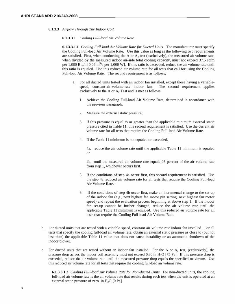
6.1.3.3.1.1 Cooling Full-load Air Volume Rate for Ducted Units. The manufacturer must specifythe Cooling Full-load Air Volume Rate. Use this value as long as the following two requirementsare satisfied. First, when conducting the A or A2 test (exclusively), the measured air volume rate,when divided by the measured indoor air-side total cooling capacity, must not exceed 37.5 scfmper 1,000 Btu/h [0.06 m3/s per 1,000 W]. If this ratio is exceeded, reduce the air volume rate untilthis ratio is equaled. Use this reduced air volume rate for all tests that call for using the CoolingFull-load Air Volume Rate. The second requirement is as follows:
a. For all ducted units tested with an indoor fan installed, except those having a variable-speed, constant-air-volume-rate indoor fan. The second requirement appliesexclusively to the A or A2 Test and is met as follows.
1. Achieve the Cooling Full-load Air Volume Rate, determined in accordance withthe previous paragraph;
2. Measure the external static pressure;
3. If this pressure is equal to or greater than the applicable minimum external staticpressure cited in Table 11, this second requirement is satisfied. Use the current airvolume rate for all tests that require the Cooling Full-load Air Volume Rate.
4. If the Table 11 minimum is not equaled or exceeded,
4a. reduce the air volume rate until the applicable Table 11 minimum is equaledor
4b. until the measured air volume rate equals 95 percent of the air volume ratefrom step 1, whichever occurs first.
5. If the conditions of step 4a occur first, this second requirement is satisfied. Usethe step 4a reduced air volume rate for all tests that require the Cooling Full-loadAir Volume Rate.
6. If the conditions of step 4b occur first, make an incremental change to the set-upof the indoor fan (e.g., next highest fan motor pin setting, next highest fan motorspeed) and repeat the evaluation process beginning at above step 1. If the indoorfan set-up cannot be further changed, reduce the air volume rate until theapplicable Table 11 minimum is equaled. Use this reduced air volume rate for alltests that require the Cooling Full-load Air Volume Rate.
b. For ducted units that are tested with a variable-speed, constant-air-volume-rate indoor fan installed. For alltests that specify the cooling full-load air volume rate, obtain an external static pressure as close to (but notless than) the applicable Table 11 value that does not cause instability or an automatic shutdown of theindoor blower.
c. For ducted units that are tested without an indoor fan installed. For the A or A2 test, (exclusively), thepressure drop across the indoor coil assembly must not exceed 0.30 in H2O [75 Pa]. If this pressure drop isexceeded, reduce the air volume rate until the measured pressure drop equals the specified maximum. Usethis reduced air volume rate for all tests that require the cooling full-load air volume rate.
6.1.3.3.1.2 Cooling Full-load Air Volume Rate for Non-ducted Units. For non-ducted units, the coolingfull-load air volume rate is the air volume rate that results during each test when the unit is operated at anexternal static pressure of zero in H2O [0 Pa].
__________________ _______________ AHRI STANDARD 210/240-2008
9
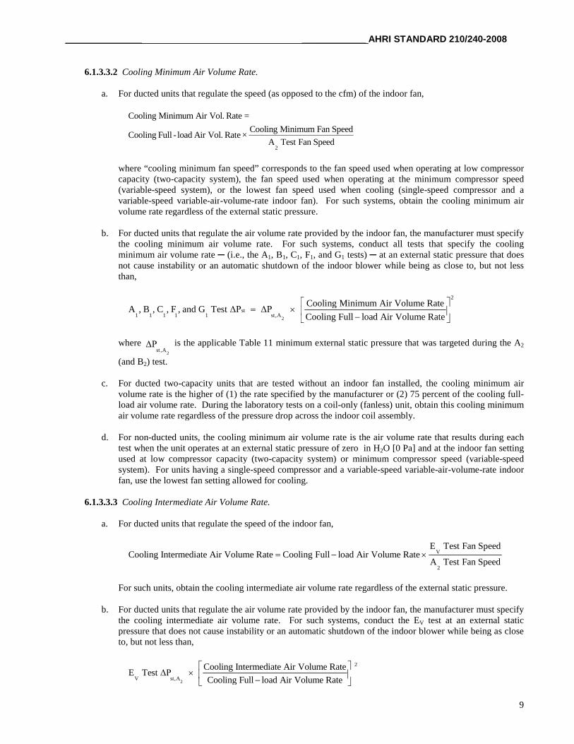
6.1.3.3.2 Cooling Minimum Air Volume Rate.
a. For ducted units that regulate the speed (as opposed to the cfm) of the indoor fan,
2
Cooling Minimum Air Vol. Rate =
Cooling Minimum Fan SpeedCooling Full - load Air Vol. Rate ×
A Test Fan Speed
where “cooling minimum fan speed” corresponds to the fan speed used when operating at low compressorcapacity (two-capacity system), the fan speed used when operating at the minimum compressor speed(variable-speed system), or the lowest fan speed used when cooling (single-speed compressor and avariable-speed variable-air-volume-rate indoor fan). For such systems, obtain the cooling minimum airvolume rate regardless of the external static pressure.
b. For ducted units that regulate the air volume rate provided by the indoor fan, the manufacturer must specifythe cooling minimum air volume rate. For such systems, conduct all tests that specify the coolingminimum air volume rate ─ (i.e., the A1, B1, C1, F1, and G1 tests) ─ at an external static pressure that doesnot cause instability or an automatic shutdown of the indoor blower while being as close to, but not lessthan,
2
2
st1 1 1 1 1 st,A
Cooling Minimum Air Volume RateA , B , C , F , and G Test ΔP ΔP
Cooling Full load Air Volume Rate
where2
st ,AΔP is the applicable Table 11 minimum external static pressure that was targeted during the A2
(and B2) test.
c. For ducted two-capacity units that are tested without an indoor fan installed, the cooling minimum airvolume rate is the higher of (1) the rate specified by the manufacturer or (2) 75 percent of the cooling full-load air volume rate. During the laboratory tests on a coil-only (fanless) unit, obtain this cooling minimumair volume rate regardless of the pressure drop across the indoor coil assembly.
d. For non-ducted units, the cooling minimum air volume rate is the air volume rate that results during eachtest when the unit operates at an external static pressure of zero in H2O [0 Pa] and at the indoor fan settingused at low compressor capacity (two-capacity system) or minimum compressor speed (variable-speedsystem). For units having a single-speed compressor and a variable-speed variable-air-volume-rate indoorfan, use the lowest fan setting allowed for cooling.
6.1.3.3.3 Cooling Intermediate Air Volume Rate.
a. For ducted units that regulate the speed of the indoor fan,
V
2
E Test Fan SpeedCooling Intermediate Air Volume Rate Cooling Full load Air Volume Rate
A Test Fan Speed
For such units, obtain the cooling intermediate air volume rate regardless of the external static pressure.
b. For ducted units that regulate the air volume rate provided by the indoor fan, the manufacturer must specifythe cooling intermediate air volume rate. For such systems, conduct the EV test at an external staticpressure that does not cause instability or an automatic shutdown of the indoor blower while being as closeto, but not less than,
2
2
V st,A
Cooling Intermediate Air Volume RateE Test ΔP
Cooling Full load Air Volume Rate
AHRI STANDARD 210/240-2008 _____________________ _____________
10
where2
st ,AΔP is the applicable Table 11 minimum external static pressure that was targeted during the A2
(and B2) test.
c. For non-ducted units, the cooling intermediate air volume rate is the air volume rate that results when theunit operates at an external static pressure of zero in H2O [0 Pa] and at the fan speed selected by thecontrols of the unit for the EV test conditions.
6.1.3.3.4 Heating Full-load Air Volume Rate.
6.1.3.3.4.1 Ducted Heat Pumps Where the Heating and Cooling Full-load Air Volume Rates Are theSame.
a. Use the cooling full-load air volume rate as the heating full-load air volume rate for:
1. Ducted heat pumps that operate at the same indoor fan speed during both the A (or A2) andthe H1 (or H12) tests;
2. Ducted heat pumps that regulate fan speed to deliver the same constant air volume rateduring both the A (or A2) and the H1 (or H12) tests; and
3. Ducted heat pumps that are tested without an indoor fan installed (except two-capacitynorthern heat pumps that are tested only at low capacity cooling - see 6.1.3.3.4.2).
b. For heat pumps that meet the above criteria “1” and “3,” no minimum requirements apply to themeasured external or internal, respectively, static pressure. For heat pumps that meet the abovecriterion “2,” test at an external static pressure that does not cause instability or an automaticshutdown of the indoor blower while being as close to, but not less than, the same Table 11minimum external static pressure as was specified for the A (or A2) cooling mode test.
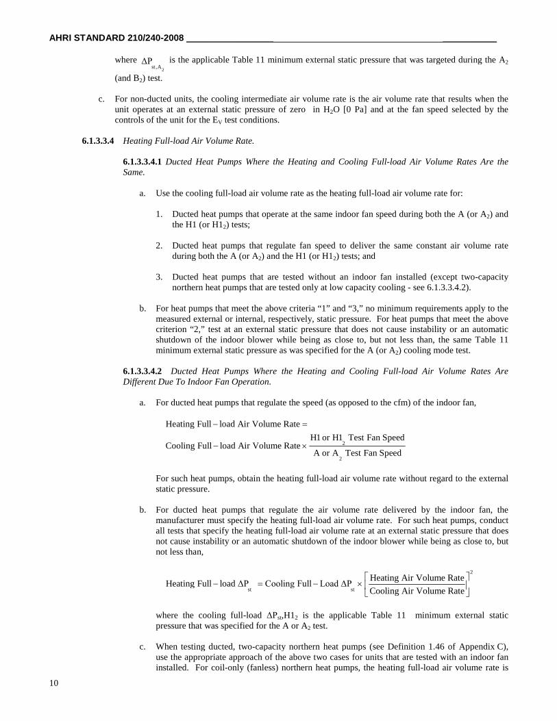
6.1.3.3.4.2 Ducted Heat Pumps Where the Heating and Cooling Full-load Air Volume Rates AreDifferent Due To Indoor Fan Operation.
a. For ducted heat pumps that regulate the speed (as opposed to the cfm) of the indoor fan,
2
2
Heating Full load Air Volume Rate
H1 or H1 Test Fan SpeedCooling Full load Air Volume Rate
A or A Test Fan Speed
For such heat pumps, obtain the heating full-load air volume rate without regard to the externalstatic pressure.
b. For ducted heat pumps that regulate the air volume rate delivered by the indoor fan, themanufacturer must specify the heating full-load air volume rate. For such heat pumps, conductall tests that specify the heating full-load air volume rate at an external static pressure that doesnot cause instability or an automatic shutdown of the indoor blower while being as close to, butnot less than,
2
st st
Heating Air Volume RateHeating Full load ΔP Cooling Full Load ΔP
Cooling Air Volume Rate
where the cooling full-load ΔPst,H12 is the applicable Table 11 minimum external staticpressure that was specified for the A or A2 test.
c. When testing ducted, two-capacity northern heat pumps (see Definition 1.46 of Appendix C),use the appropriate approach of the above two cases for units that are tested with an indoor faninstalled. For coil-only (fanless) northern heat pumps, the heating full-load air volume rate is
__________________ _______________ AHRI STANDARD 210/240-2008
11
the lesser of the rate specified by the manufacturer or 133 percent of the cooling full-load airvolume rate. For this latter case, obtain the heating full-load air volume rate regardless of thepressure drop across the indoor coil assembly.
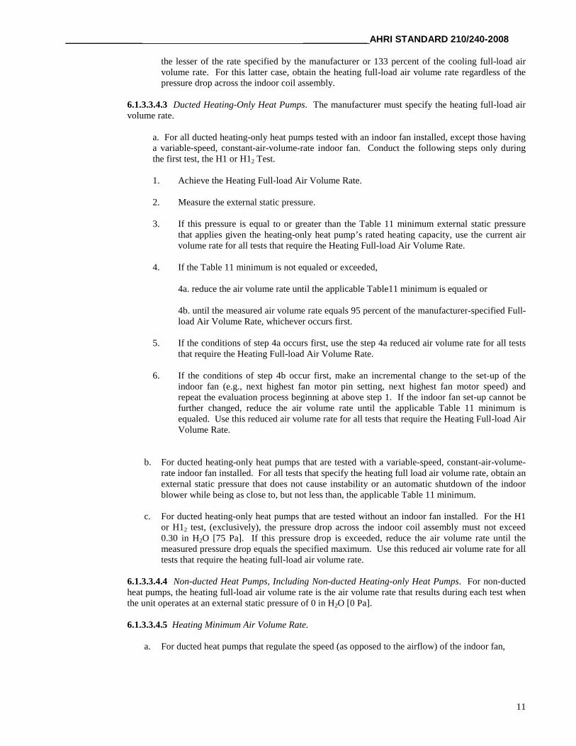
6.1.3.3.4.3 Ducted Heating-Only Heat Pumps. The manufacturer must specify the heating full-load airvolume rate.
a. For all ducted heating-only heat pumps tested with an indoor fan installed, except those havinga variable-speed, constant-air-volume-rate indoor fan. Conduct the following steps only duringthe first test, the H1 or H12 Test.
1. Achieve the Heating Full-load Air Volume Rate.
2. Measure the external static pressure.
3. If this pressure is equal to or greater than the Table 11 minimum external static pressurethat applies given the heating-only heat pump’s rated heating capacity, use the current airvolume rate for all tests that require the Heating Full-load Air Volume Rate.
4. If the Table 11 minimum is not equaled or exceeded,
4a. reduce the air volume rate until the applicable Table11 minimum is equaled or
4b. until the measured air volume rate equals 95 percent of the manufacturer-specified Full-load Air Volume Rate, whichever occurs first.
5. If the conditions of step 4a occurs first, use the step 4a reduced air volume rate for all teststhat require the Heating Full-load Air Volume Rate.
6. If the conditions of step 4b occur first, make an incremental change to the set-up of theindoor fan (e.g., next highest fan motor pin setting, next highest fan motor speed) andrepeat the evaluation process beginning at above step 1. If the indoor fan set-up cannot befurther changed, reduce the air volume rate until the applicable Table 11 minimum isequaled. Use this reduced air volume rate for all tests that require the Heating Full-load AirVolume Rate.
b. For ducted heating-only heat pumps that are tested with a variable-speed, constant-air-volume-rate indoor fan installed. For all tests that specify the heating full load air volume rate, obtain anexternal static pressure that does not cause instability or an automatic shutdown of the indoorblower while being as close to, but not less than, the applicable Table 11 minimum.
c. For ducted heating-only heat pumps that are tested without an indoor fan installed. For the H1or H12 test, (exclusively), the pressure drop across the indoor coil assembly must not exceed0.30 in H2O [75 Pa]. If this pressure drop is exceeded, reduce the air volume rate until themeasured pressure drop equals the specified maximum. Use this reduced air volume rate for alltests that require the heating full-load air volume rate.
6.1.3.3.4.4 Non-ducted Heat Pumps, Including Non-ducted Heating-only Heat Pumps. For non-ductedheat pumps, the heating full-load air volume rate is the air volume rate that results during each test whenthe unit operates at an external static pressure of 0 in H2O [0 Pa].
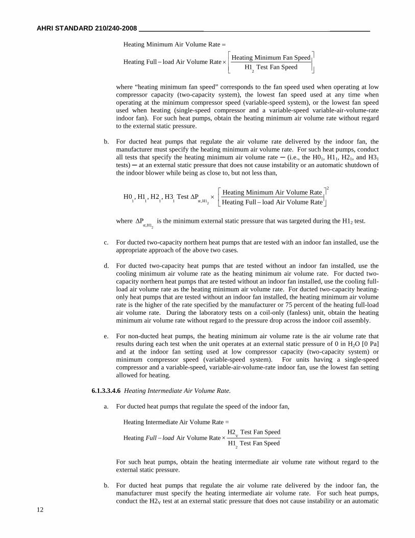
6.1.3.3.4.5 Heating Minimum Air Volume Rate.
a. For ducted heat pumps that regulate the speed (as opposed to the airflow) of the indoor fan,
AHRI STANDARD 210/240-2008 _____________________ _____________
12
2
Heating Minimum Air Volume Rate
Heating Minimum Fan SpeedHeating Full load Air Volume Rate
H1 Test Fan Speed
where “heating minimum fan speed” corresponds to the fan speed used when operating at lowcompressor capacity (two-capacity system), the lowest fan speed used at any time whenoperating at the minimum compressor speed (variable-speed system), or the lowest fan speedused when heating (single-speed compressor and a variable-speed variable-air-volume-rateindoor fan). For such heat pumps, obtain the heating minimum air volume rate without regardto the external static pressure.
b. For ducted heat pumps that regulate the air volume rate delivered by the indoor fan, themanufacturer must specify the heating minimum air volume rate. For such heat pumps, conductall tests that specify the heating minimum air volume rate ─ (i.e., the H01, H11, H21, and H31
tests) ─ at an external static pressure that does not cause instability or an automatic shutdown ofthe indoor blower while being as close to, but not less than,
2
2
1 1 1 1 st ,H1
Heating Minimum Air Volume RateH0 , H1 , H2 , H3 Test P
Heating Full load Air Volume Rate
where2
st,H1ΔP is the minimum external static pressure that was targeted during the H12 test.
c. For ducted two-capacity northern heat pumps that are tested with an indoor fan installed, use theappropriate approach of the above two cases.
d. For ducted two-capacity heat pumps that are tested without an indoor fan installed, use thecooling minimum air volume rate as the heating minimum air volume rate. For ducted two-capacity northern heat pumps that are tested without an indoor fan installed, use the cooling full-load air volume rate as the heating minimum air volume rate. For ducted two-capacity heating-only heat pumps that are tested without an indoor fan installed, the heating minimum air volumerate is the higher of the rate specified by the manufacturer or 75 percent of the heating full-loadair volume rate. During the laboratory tests on a coil-only (fanless) unit, obtain the heatingminimum air volume rate without regard to the pressure drop across the indoor coil assembly.
e. For non-ducted heat pumps, the heating minimum air volume rate is the air volume rate thatresults during each test when the unit operates at an external static pressure of 0 in H2O [0 Pa]and at the indoor fan setting used at low compressor capacity (two-capacity system) orminimum compressor speed (variable-speed system). For units having a single-speedcompressor and a variable-speed, variable-air-volume-rate indoor fan, use the lowest fan settingallowed for heating.
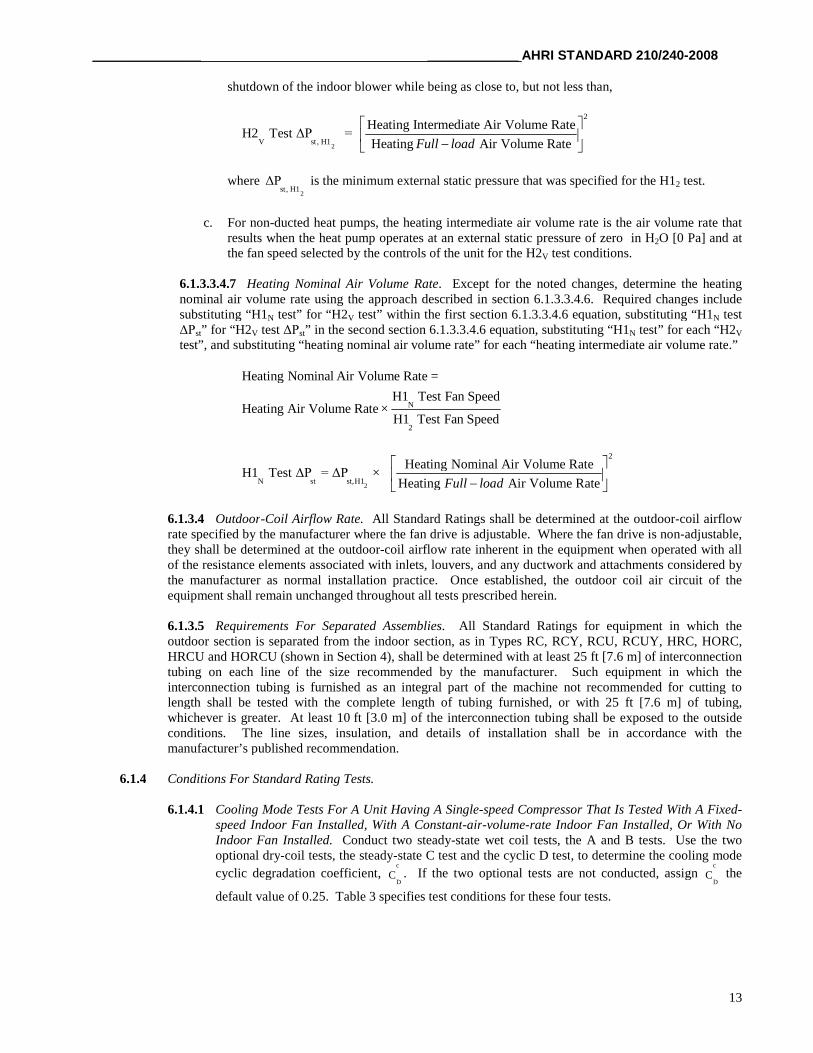
6.1.3.3.4.6 Heating Intermediate Air Volume Rate.
a. For ducted heat pumps that regulate the speed of the indoor fan,
V
2
Heating Intermediate Air Volume Rate =
H2 Test Fan SpeedHeating Air Volume Rate ×
H1 Test Fan SpeedFull load
For such heat pumps, obtain the heating intermediate air volume rate without regard to theexternal static pressure.
b. For ducted heat pumps that regulate the air volume rate delivered by the indoor fan, themanufacturer must specify the heating intermediate air volume rate. For such heat pumps,conduct the H2V test at an external static pressure that does not cause instability or an automatic
__________________ _______________ AHRI STANDARD 210/240-2008
13
shutdown of the indoor blower while being as close to, but not less than,
2
2
V st , H1
Heating Intermediate Air Volume RateH2 Test ΔP =
Heating Air Volume RateFull load
where2
st, H1ΔP is the minimum external static pressure that was specified for the H12 test.
c. For non-ducted heat pumps, the heating intermediate air volume rate is the air volume rate thatresults when the heat pump operates at an external static pressure of zero in H2O [0 Pa] and atthe fan speed selected by the controls of the unit for the H2V test conditions.
6.1.3.3.4.7 Heating Nominal Air Volume Rate. Except for the noted changes, determine the heatingnominal air volume rate using the approach described in section 6.1.3.3.4.6. Required changes includesubstituting “H1N test” for “H2V test” within the first section 6.1.3.3.4.6 equation, substituting “H1N testΔPst” for “H2V test ΔPst” in the second section 6.1.3.3.4.6 equation, substituting “H1N test” for each “H2V
test”, and substituting “heating nominal air volume rate” for each “heating intermediate air volume rate.”
N
2
Heating Nominal Air Volume Rate =
H1 Test Fan SpeedHeating Air Volume Rate ×
H1 Test Fan Speed
2
2
N st st,H1
Heating Nominal Air Volume RateH1 Test ΔP = ΔP ×
Heating Air Volume Rate
Full load
6.1.3.4 Outdoor-Coil Airflow Rate. All Standard Ratings shall be determined at the outdoor-coil airflowrate specified by the manufacturer where the fan drive is adjustable. Where the fan drive is non-adjustable,they shall be determined at the outdoor-coil airflow rate inherent in the equipment when operated with allof the resistance elements associated with inlets, louvers, and any ductwork and attachments considered bythe manufacturer as normal installation practice. Once established, the outdoor coil air circuit of theequipment shall remain unchanged throughout all tests prescribed herein.
6.1.3.5 Requirements For Separated Assemblies. All Standard Ratings for equipment in which theoutdoor section is separated from the indoor section, as in Types RC, RCY, RCU, RCUY, HRC, HORC,HRCU and HORCU (shown in Section 4), shall be determined with at least 25 ft [7.6 m] of interconnectiontubing on each line of the size recommended by the manufacturer. Such equipment in which theinterconnection tubing is furnished as an integral part of the machine not recommended for cutting tolength shall be tested with the complete length of tubing furnished, or with 25 ft [7.6 m] of tubing,whichever is greater. At least 10 ft [3.0 m] of the interconnection tubing shall be exposed to the outsideconditions. The line sizes, insulation, and details of installation shall be in accordance with themanufacturer’s published recommendation.
6.1.4 Conditions For Standard Rating Tests.
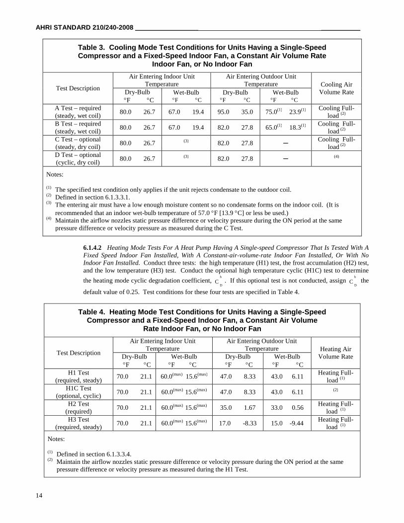
6.1.4.1 Cooling Mode Tests For A Unit Having A Single-speed Compressor That Is Tested With A Fixed-speed Indoor Fan Installed, With A Constant-air-volume-rate Indoor Fan Installed, Or With NoIndoor Fan Installed. Conduct two steady-state wet coil tests, the A and B tests. Use the twooptional dry-coil tests, the steady-state C test and the cyclic D test, to determine the cooling mode
cyclic degradation coefficient,c
DC . If the two optional tests are not conducted, assign
c
DC the
default value of 0.25. Table 3 specifies test conditions for these four tests.
AHRI STANDARD 210/240-2008 _____________________ _____________
14
Table 3. Cooling Mode Test Conditions for Units Having a Single-SpeedCompressor and a Fixed-Speed Indoor Fan, a Constant Air Volume Rate
Indoor Fan, or No Indoor Fan
Test Description
Air Entering Indoor UnitTemperature
Air Entering Outdoor UnitTemperature Cooling Air
Volume RateDry-BulbF C
Wet-BulbF C
Dry-BulbF C
Wet-BulbF C
A Test – required(steady, wet coil)
80.0 26.7 67.0 19.4 95.0 35.0 75.0(1) 23.9(1) Cooling Full-load (2)
B Test – required(steady, wet coil)
80.0 26.7 67.0 19.4 82.0 27.8 65.0(1) 18.3(1) Cooling Full-load (2)
C Test – optional(steady, dry coil)
80.0 26.7 (3) 82.0 27.8 ─Cooling Full-
load (2)
D Test – optional(cyclic, dry coil)
80.0 26.7 (3) 82.0 27.8 ─ (4)
Notes:
(1) The specified test condition only applies if the unit rejects condensate to the outdoor coil.(2) Defined in section 6.1.3.3.1.(3) The entering air must have a low enough moisture content so no condensate forms on the indoor coil. (It is
recommended that an indoor wet-bulb temperature of 57.0 F [13.9 C] or less be used.)(4) Maintain the airflow nozzles static pressure difference or velocity pressure during the ON period at the same
pressure difference or velocity pressure as measured during the C Test.
6.1.4.2 Heating Mode Tests For A Heat Pump Having A Single-speed Compressor That Is Tested With AFixed Speed Indoor Fan Installed, With A Constant-air-volume-rate Indoor Fan Installed, Or With NoIndoor Fan Installed. Conduct three tests: the high temperature (H1) test, the frost accumulation (H2) test,and the low temperature (H3) test. Conduct the optional high temperature cyclic (H1C) test to determine
the heating mode cyclic degradation coefficient,h
DC . If this optional test is not conducted, assign
h
DC the
default value of 0.25. Test conditions for these four tests are specified in Table 4.
Table 4. Heating Mode Test Conditions for Units Having a Single-SpeedCompressor and a Fixed-Speed Indoor Fan, a Constant Air Volume
Rate Indoor Fan, or No Indoor Fan
Test Description
Air Entering Indoor UnitTemperature
Air Entering Outdoor UnitTemperature Heating Air
Volume RateDry-BulbF C
Wet-BulbF C
Dry-BulbF C
Wet-BulbF C
H1 Test(required, steady)
70.0 21.1 60.0(max) 15.6(max) 47.0 8.33 43.0 6.11Heating Full-
load (1)
H1C Test(optional, cyclic)
70.0 21.1 60.0(max) 15.6(max) 47.0 8.33 43.0 6.11 (2)
H2 Test(required)
70.0 21.1 60.0(max) 15.6(max) 35.0 1.67 33.0 0.56Heating Full-
load (1)
H3 Test(required, steady)
70.0 21.1 60.0(max) 15.6(max) 17.0 -8.33 15.0 -9.44Heating Full-
load (1)
Notes:
(1) Defined in section 6.1.3.3.4.(2) Maintain the airflow nozzles static pressure difference or velocity pressure during the ON period at the same
pressure difference or velocity pressure as measured during the H1 Test.
__________________ _______________ AHRI STANDARD 210/240-2008
15
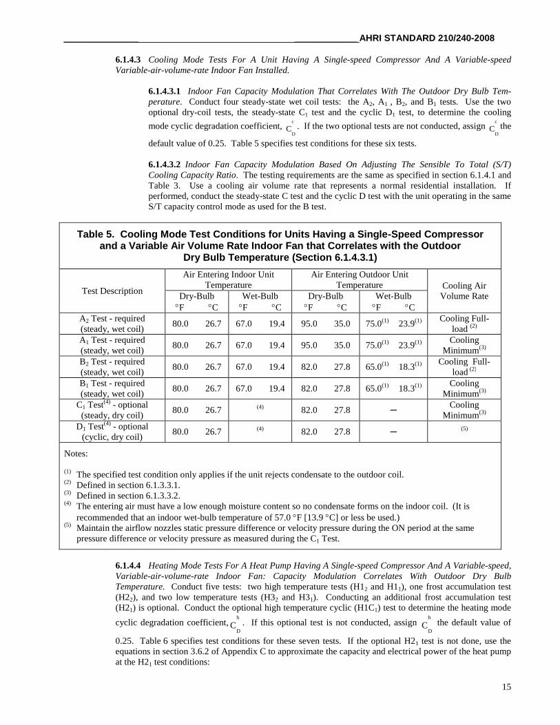
6.1.4.3 Cooling Mode Tests For A Unit Having A Single-speed Compressor And A Variable-speedVariable-air-volume-rate Indoor Fan Installed.
6.1.4.3.1 Indoor Fan Capacity Modulation That Correlates With The Outdoor Dry Bulb Tem-perature. Conduct four steady-state wet coil tests: the A2, A1 , B2, and B1 tests. Use the twooptional dry-coil tests, the steady-state C1 test and the cyclic D1 test, to determine the cooling
mode cyclic degradation coefficient,c
DC . If the two optional tests are not conducted, assign
c
DC the
default value of 0.25. Table 5 specifies test conditions for these six tests.
6.1.4.3.2 Indoor Fan Capacity Modulation Based On Adjusting The Sensible To Total (S/T)Cooling Capacity Ratio. The testing requirements are the same as specified in section 6.1.4.1 andTable 3. Use a cooling air volume rate that represents a normal residential installation. Ifperformed, conduct the steady-state C test and the cyclic D test with the unit operating in the sameS/T capacity control mode as used for the B test.
Table 5. Cooling Mode Test Conditions for Units Having a Single-Speed Compressorand a Variable Air Volume Rate Indoor Fan that Correlates with the Outdoor
Dry Bulb Temperature (Section 6.1.4.3.1)
Test Description
Air Entering Indoor UnitTemperature
Air Entering Outdoor UnitTemperature Cooling Air
Volume RateDry-BulbF C
Wet-BulbF C
Dry-BulbF C
Wet-BulbF C
A2 Test - required(steady, wet coil)
80.0 26.7 67.0 19.4 95.0 35.0 75.0(1) 23.9(1) Cooling Full-load (2)
A1 Test - required(steady, wet coil)
80.0 26.7 67.0 19.4 95.0 35.0 75.0(1) 23.9(1) CoolingMinimum(3)
B2 Test - required(steady, wet coil)
80.0 26.7 67.0 19.4 82.0 27.8 65.0(1) 18.3(1) Cooling Full-load (2)
B1 Test - required(steady, wet coil)
80.0 26.7 67.0 19.4 82.0 27.8 65.0(1) 18.3(1) CoolingMinimum(3)
C1 Test(4) - optional(steady, dry coil)
80.0 26.7 (4) 82.0 27.8 ─Cooling
Minimum(3)
D1 Test(4) - optional(cyclic, dry coil)
80.0 26.7 (4) 82.0 27.8 ─ (5)
Notes:
(1) The specified test condition only applies if the unit rejects condensate to the outdoor coil.(2) Defined in section 6.1.3.3.1.(3) Defined in section 6.1.3.3.2.(4) The entering air must have a low enough moisture content so no condensate forms on the indoor coil. (It is
recommended that an indoor wet-bulb temperature of 57.0 F [13.9 C] or less be used.)(5) Maintain the airflow nozzles static pressure difference or velocity pressure during the ON period at the same
pressure difference or velocity pressure as measured during the C1 Test.
6.1.4.4 Heating Mode Tests For A Heat Pump Having A Single-speed Compressor And A Variable-speed,Variable-air-volume-rate Indoor Fan: Capacity Modulation Correlates With Outdoor Dry BulbTemperature. Conduct five tests: two high temperature tests (H12 and H11), one frost accumulation test(H22), and two low temperature tests (H32 and H31). Conducting an additional frost accumulation test(H21) is optional. Conduct the optional high temperature cyclic (H1C1) test to determine the heating mode
cyclic degradation coefficient,h
DC . If this optional test is not conducted, assign
h
DC the default value of
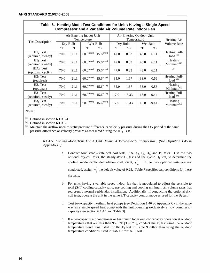
0.25. Table 6 specifies test conditions for these seven tests. If the optional H21 test is not done, use theequations in section 3.6.2 of Appendix C to approximate the capacity and electrical power of the heat pumpat the H21 test conditions:
AHRI STANDARD 210/240-2008 _____________________ _____________
16
Table 6. Heating Mode Test Conditions for Units Having a Single-SpeedCompressor and a Variable Air Volume Rate Indoor Fan
Test Description
Air Entering Indoor UnitTemperature
Air Entering Outdoor UnitTemperature Heating Air
Volume RateDry-BulbF C
Wet-BulbF C
Dry-BulbF C
Wet-BulbF C
H12 Test(required, steady)
70.0 21.1 60.0(max) 15.6(max) 47.0 8.33 43.0 6.11Heating Full-
load (1)
H11 Test(required, steady)
70.0 21.1 60.0(max) 15.6(max) 47.0 8.33 43.0 6.11Heating
Minimum(2)
H1C1 Test(optional, cyclic)
70.0 21.1 60.0(max) 15.6(max) 47.0 8.33 43.0 6.11 (3)
H22 Test(required)
70.0 21.1 60.0(max) 15.6(max) 35.0 1.67 33.0 0.56Heating Full-
load (1)
H21 Test(optional)
70.0 21.1 60.0(max) 15.6(max) 35.0 1.67 33.0 0.56Heating
Minimum(2)
H32 Test(required, steady)
70.0 21.1 60.0(max) 15.6(max) 17.0 -8.33 15.0 -9.44Heating Full-
load (1)
H31 Test(required, steady)
70.0 21.1 60.0(max) 15.6(max) 17.0 -8.33 15.0 -9.44Heating
Minimum(2)
Notes:
(1) Defined in section 6.1.3.3.4.(2) Defined in section 6.1.3.3.5.(3) Maintain the airflow nozzles static pressure difference or velocity pressure during the ON period at the same
pressure difference or velocity pressure as measured during the H11 Test.
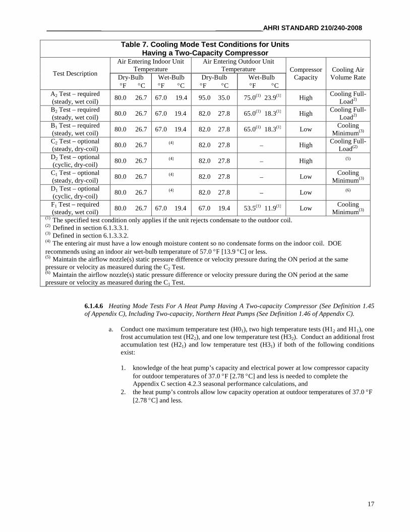
6.1.4.5 Cooling Mode Tests For A Unit Having A Two-capacity Compressor. (See Definition 1.45 inAppendix C.)
a. Conduct four steady-state wet coil tests: the A2, F1, B2, and B1 tests. Use the twooptional dry-coil tests, the steady-state C1 test and the cyclic D1 test, to determine the
cooling mode cyclic degradation coefficient,c
DC . If the two optional tests are not
conducted, assignc
DC the default value of 0.25. Table 7 specifies test conditions for these
six tests.
b. For units having a variable speed indoor fan that is modulated to adjust the sensible tototal (S/T) cooling capacity ratio, use cooling and cooling minimum air volume rates thatrepresent a normal residential installation. Additionally, if conducting the optional dry-coil tests, operate the unit in the same S/T capacity control mode as used for the B1 test.
c. Test two-capacity, northern heat pumps (see Definition 1.46 of Appendix C) in the sameway as a single speed heat pump with the unit operating exclusively at low compressorcapacity (see section 6.1.4.1 and Table 3).
d. If a two-capacity air conditioner or heat pump locks out low capacity operation at outdoortemperatures that are less than 95.0 °F [35.0 °C], conduct the F1 test using the outdoortemperature conditions listed for the F1 test in Table 9 rather than using the outdoortemperature conditions listed in Table 7 for the F1 test.
__________________ _______________ AHRI STANDARD 210/240-2008
17
Table 7. Cooling Mode Test Conditions for UnitsHaving a Two-Capacity Compressor
Test Description
Air Entering Indoor UnitTemperature
Air Entering Outdoor UnitTemperature Compressor
CapacityCooling Air
Volume RateDry-BulbF C
Wet-BulbF C
Dry-BulbF C
Wet-BulbF C
A2 Test – required(steady, wet coil)
80.0 26.7 67.0 19.4 95.0 35.0 75.0(1) 23.9(1) HighCooling Full-
Load2)
B2 Test – required(steady, wet coil)
80.0 26.7 67.0 19.4 82.0 27.8 65.0(1) 18.3(1) HighCooling Full-
Load2)
B1 Test – required(steady, wet coil)
80.0 26.7 67.0 19.4 82.0 27.8 65.0(1) 18.3(1) LowCooling
Minimum(3)
C2 Test – optional(steady, dry-coil)
80.0 26.7 (4) 82.0 27.8 HighCooling Full-
Load(2)
D2 Test – optional(cyclic, dry-coil)
80.0 26.7 (4) 82.0 27.8 High (5)
C1 Test – optional(steady, dry-coil)
80.0 26.7 (4) 82.0 27.8 LowCooling
Minimum(3)
D1 Test – optional(cyclic, dry-coil)
80.0 26.7 (4) 82.0 27.8 Low (6)
F1 Test – required(steady, wet coil)
80.0 26.7 67.0 19.4 67.0 19.4 53.5(1) 11.9(1) LowCooling
Minimum(3)
(1) The specified test condition only applies if the unit rejects condensate to the outdoor coil.(2) Defined in section 6.1.3.3.1.(3) Defined in section 6.1.3.3.2.(4) The entering air must have a low enough moisture content so no condensate forms on the indoor coil. DOErecommends using an indoor air wet-bulb temperature of 57.0 F [13.9 C] or less.(5) Maintain the airflow nozzle(s) static pressure difference or velocity pressure during the ON period at the samepressure or velocity as measured during the C2 Test.(6) Maintain the airflow nozzle(s) static pressure difference or velocity pressure during the ON period at the samepressure or velocity as measured during the C1 Test.
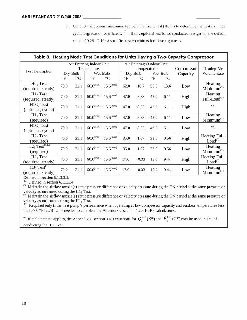
6.1.4.6 Heating Mode Tests For A Heat Pump Having A Two-capacity Compressor (See Definition 1.45of Appendix C), Including Two-capacity, Northern Heat Pumps (See Definition 1.46 of Appendix C).
a. Conduct one maximum temperature test (H01), two high temperature tests (H12 and H11), onefrost accumulation test (H22), and one low temperature test (H32). Conduct an additional frostaccumulation test (H21) and low temperature test (H31) if both of the following conditionsexist:
1. knowledge of the heat pump’s capacity and electrical power at low compressor capacityfor outdoor temperatures of 37.0 F [2.78 C] and less is needed to complete theAppendix C section 4.2.3 seasonal performance calculations, and
2. the heat pump’s controls allow low capacity operation at outdoor temperatures of 37.0 F[2.78 C] and less.
AHRI STANDARD 210/240-2008 _____________________ _____________
18
b. Conduct the optional maximum temperature cyclic test (H0C1) to determine the heating mode
cyclic degradation coefficient,h
DC . If this optional test is not conducted, assign
h
DC the default
value of 0.25. Table 8 specifies test conditions for these eight tests.
Table 8. Heating Mode Test Conditions for Units Having a Two-Capacity Compressor
Test Description
Air Entering Indoor UnitTemperature
Air Entering Outdoor UnitTemperature Compressor
CapacityHeating Air
Volume RateDry-BulbF C
Wet-BulbF C
Dry-BulbF C
Wet-BulbF C
H01 Test(required, steady)
70.0 21.1 60.0(max) 15.6(max) 62.0 16.7 56.5 13.6 LowHeating
Minimum(1)
H12 Test(required, steady)
70.0 21.1 60.0(max) 15.6(max) 47.0 8.33 43.0 6.11 HighHeating
Full-Load(2)
H1C2 Test(optional, cyclic)
70.0 21.1 60.0(max) 15.6(max) 47.0 8.33 43.0 6.11 High (3)
H11 Test(required)
70.0 21.1 60.0(max) 15.6(max) 47.0 8.33 43.0 6.11 LowHeating
Minimum(1)
H1C1 Test(optional, cyclic)
70.0 21.1 60.0(max) 15.6(max) 47.0 8.33 43.0 6.11 Low (4)
H22 Test(required)
70.0 21.1 60.0(max) 15.6(max) 35.0 1.67 33.0 0.56 HighHeating Full-
Load(2)
H21 Test(5,6)
(required)70.0 21.1 60.0(max) 15.6(max) 35.0 1.67 33.0 0.56 Low
HeatingMinimum(1)
H31 Test(required, steady)
70.0 21.1 60.0(max) 15.6(max) 17.0 -8.33 15.0 -9.44 HighHeating Full-
Load(2)
H31 Test(5)
(required, steady)70.0 21.1 60.0(max) 15.6(max) 17.0 -8.33 15.0 -9.44 Low
HeatingMinimum(1)
Defined in section 6.1.3.3.5.(2) Defined in section 6.1.3.3.4.
(3) Maintain the airflow nozzle(s) static pressure difference or velocity pressure during the ON period at the same pressure orvelocity as measured during the H12 Test.(4) Maintain the airflow nozzle(s) static pressure difference or velocity pressure during the ON period at the same pressure orvelocity as measured during the H11 Test.(5) Required only if the heat pump’s performance when operating at low compressor capacity and outdoor temperatures lessthan 37.0 F [2.78 C] is needed to complete the Appendix C section 4.2.3 HSPF calculations.
(6) If table note #5 applies, the Appendix C section 3.6.3 equations for )(35Q 1kh and )(17E 1k
h may be used in lieu of
conducting the H21 Test.
__________________ _______________ AHRI STANDARD 210/240-2008
19
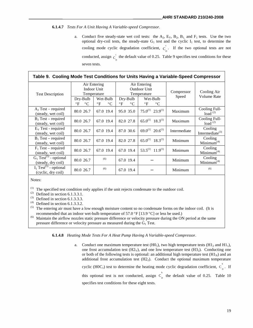
6.1.4.7 Tests For A Unit Having A Variable-speed Compressor.
a. Conduct five steady-state wet coil tests: the A2, EV, B2, B1, and F1 tests. Use the twooptional dry-coil tests, the steady-state G1 test and the cyclic I1 test, to determine the
cooling mode cyclic degradation coefficient,c
DC . If the two optional tests are not
conducted, assignc
DC the default value of 0.25. Table 9 specifies test conditions for these
seven tests.
Table 9. Cooling Mode Test Conditions for Units Having a Variable-Speed Compressor
Test Description
Air EnteringIndoor UnitTemperature
Air EnteringOutdoor UnitTemperature
CompressorSpeed
Cooling AirVolume Rate
Dry-BulbF C
Wet-BulbF C
Dry-BulbF C
Wet-BulbF C
A2 Test – required(steady, wet coil)
80.0 26.7 67.0 19.4 95.0 35.0 75.0(1) 23.9(1) MaximumCooling Full-
load (2)
B2 Test – required(steady, wet coil)
80.0 26.7 67.0 19.4 82.0 27.8 65.0(1) 18.3(1) MaximumCooling Full-
load (2)
EV Test - required(steady, wet coil)
80.0 26.7 67.0 19.4 87.0 30.6 69.0(1) 20.6(1) IntermediateCooling
Intermediate(3)
B1 Test – required(steady, wet coil)
80.0 26.7 67.0 19.4 82.0 27.8 65.0(1) 18.3(1) MinimumCooling
Minimum(4)
F1 Test – required(steady, wet coil)
80.0 26.7 67.0 19.4 67.0 19.4 53.5(1) 11.9(1) MinimumCooling
Minimum(4)
G1 Test(5) - optional(steady, dry coil)
80.0 26.7 (6) 67.0 19.4 ─ MinimumCooling
Minimum(4)
I1 Test(5) - optional(cyclic, dry coil)
80.0 26.7 (6) 67.0 19.4 ─ Minimum (6)
Notes:
(1) The specified test condition only applies if the unit rejects condensate to the outdoor coil.(2) Defined in section 6.1.3.3.1.(3) Defined in section 6.1.3.3.3.(4) Defined in section 6.1.3.3.2.(5) The entering air must have a low enough moisture content so no condensate forms on the indoor coil. (It is
recommended that an indoor wet-bulb temperature of 57.0 F [13.9 C] or less be used.)(6) Maintain the airflow nozzles static pressure difference or velocity pressure during the ON period at the same
pressure difference or velocity pressure as measured during the G1 Test.
6.1.4.8 Heating Mode Tests For A Heat Pump Having A Variable-speed Compressor.
a. Conduct one maximum temperature test (H01), two high temperature tests (H12 and H11),one frost accumulation test (H2V), and one low temperature test (H32). Conducting oneor both of the following tests is optional: an additional high temperature test (H1N) and anadditional frost accumulation test (H22). Conduct the optional maximum temperature
cyclic (H0C1) test to determine the heating mode cyclic degradation coefficient,h
DC . If
this optional test is not conducted, assignh
DC the default value of 0.25. Table 10
specifies test conditions for these eight tests.
AHRI STANDARD 210/240-2008 _____________________ _____________
20
Table 10. Heating Mode Test Conditions for Units Having a Variable-Speed Compressor
Test Description
Air EnteringIndoor UnitTemperature
Air EnteringOutdoor UnitTemperature
CompressorSpeed
Heating AirVolume Rate
Dry-BulbF C
Wet-BulbF C
Dry-BulbF C
Wet-BulbF C
H01 Test(required, steady)
70.0 21.1 60.0(max) 15.6(max) 62.0 16.7 56.5 13.6 MinimumHeating
Minimum(1)
H0C1 Test(optional, cyclic)
70.0 21.1 60.0(max) 15.6(max) 62.0 16.7 56.5 13.6 Minimum (2)
H12 Test(required, steady)
70.0 21.1 60.0(max) 15.6(max) 47.0 8.33 43.0 6.11 MaximumHeating Full-
load (3)
H11 Test(required, steady)
70.0 21.1 60.0(max) 15.6(max) 47.0 8.33 43.0 6.11 MinimumHeating
Minimum(1)
H1N Test(optional, steady)
70.0 21.1 60.0(max) 15.6(max) 47.0 8.33 43.0 6.11Cooling Mode
MaximumHeating
Nominal(4)
H22 Test(optional)
70.0 21.1 60.0(max) 15.6(max) 35.0 1.67 33.0 0.56 MaximumHeating Full-
load (3)
H2V Test(required)
70.0 21.1 60.0(max) 15.6(max) 35.0 1.67 33.0 0.56 IntermediateHeating
Intermediate(5)
H32 Test(required, steady)
70.0 21.1 60.0(max) 15.6(max) 17.0 -8.33 15.0 -9.44 MaximumHeating Full-
load (3)
Notes:
(1) Defined in section 6.1.3.3.5.(2) Maintain the airflow nozzles static pressure difference or velocity pressure during the ON period at the same pressure
difference or velocity pressure as measured during the H01 Test.(3) Defined in section 6.1.3.3.4.(4) Defined in section 6.1.3.3.7.(5) Defined in section 6.1.3.3.6.
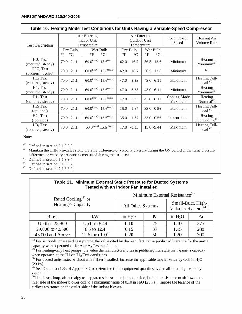
Table 11. Minimum External Static Pressure for Ducted SystemsTested with an Indoor Fan Installed
Rated Cooling(1) orHeating(2) Capacity
Minimum External Resistance(3)
All Other SystemsSmall-Duct, High-
Velocity Systems(4,5)
Btu/h kW in H2O Pa in H2O Pa
Up thru 28,800 Up thru 8.44 0.10 25 1.10 27529,000 to 42,500 8.5 to 12.4 0.15 37 1.15 288
43,000 and Above 12.6 thru 19.0 0.20 50 1.20 300(1) For air conditioners and heat pumps, the value cited by the manufacturer in published literature for the unit’scapacity when operated at the A or A2 Test conditions.(2) For heating-only heat pumps, the value the manufacturer cites in published literature for the unit’s capacitywhen operated at the H1 or H12 Test conditions.(3) For ducted units tested without an air filter installed, increase the applicable tabular value by 0.08 in H2O[20 Pa].(4) See Definition 1.35 of Appendix C to determine if the equipment qualifies as a small-duct, high-velocitysystem.(5) If a closed-loop, air-enthalpy test apparatus is used on the indoor side, limit the resistance to airflow on theinlet side of the indoor blower coil to a maximum value of 0.10 in H2O [25 Pa]. Impose the balance of theairflow resistance on the outlet side of the indoor blower.
__________________ _______________ AHRI STANDARD 210/240-2008
21
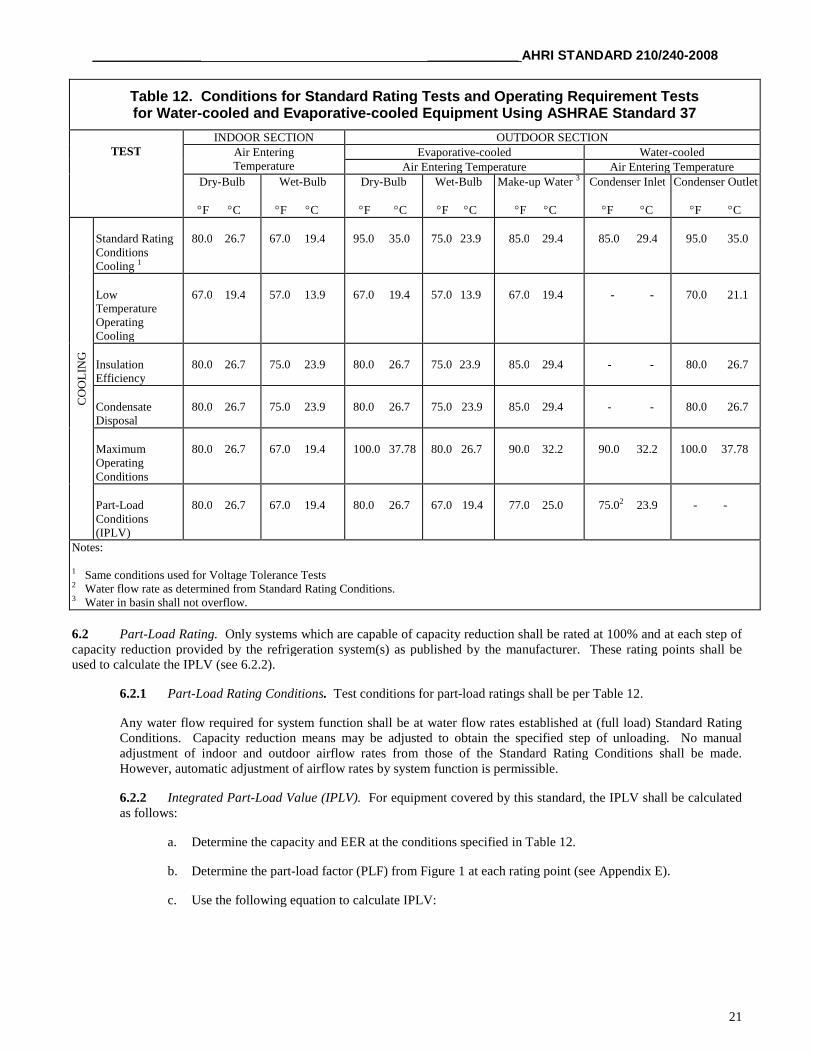
Table 12. Conditions for Standard Rating Tests and Operating Requirement Testsfor Water-cooled and Evaporative-cooled Equipment Using ASHRAE Standard 37
TESTINDOOR SECTION OUTDOOR SECTION
Air EnteringTemperature
Evaporative-cooled Water-cooledAir Entering Temperature Air Entering Temperature
Dry-Bulb
F C
Wet-Bulb
F C
Dry-Bulb
F C
Wet-Bulb
F C
Make-up Water 3
F C
Condenser Inlet
F C
Condenser Outlet
F C
CO
OL
ING
Standard RatingConditionsCooling 1
80.0 26.7 67.0 19.4 95.0 35.0 75.0 23.9 85.0 29.4 85.0 29.4 95.0 35.0
LowTemperatureOperatingCooling
67.0 19.4 57.0 13.9 67.0 19.4 57.0 13.9 67.0 19.4 - - 70.0 21.1
InsulationEfficiency
80.0 26.7 75.0 23.9 80.0 26.7 75.0 23.9 85.0 29.4 - - 80.0 26.7
CondensateDisposal
80.0 26.7 75.0 23.9 80.0 26.7 75.0 23.9 85.0 29.4 - - 80.0 26.7
MaximumOperatingConditions
80.0 26.7 67.0 19.4 100.0 37.78 80.0 26.7 90.0 32.2 90.0 32.2 100.0 37.78
Part-LoadConditions(IPLV)
80.0 26.7 67.0 19.4 80.0 26.7 67.0 19.4 77.0 25.0 75.02 23.9 - -
Notes:
1 Same conditions used for Voltage Tolerance Tests2 Water flow rate as determined from Standard Rating Conditions.3 Water in basin shall not overflow.
6.2 Part-Load Rating. Only systems which are capable of capacity reduction shall be rated at 100% and at each step ofcapacity reduction provided by the refrigeration system(s) as published by the manufacturer. These rating points shall beused to calculate the IPLV (see 6.2.2).
6.2.1 Part-Load Rating Conditions. Test conditions for part-load ratings shall be per Table 12.
Any water flow required for system function shall be at water flow rates established at (full load) Standard RatingConditions. Capacity reduction means may be adjusted to obtain the specified step of unloading. No manualadjustment of indoor and outdoor airflow rates from those of the Standard Rating Conditions shall be made.However, automatic adjustment of airflow rates by system function is permissible.
6.2.2 Integrated Part-Load Value (IPLV). For equipment covered by this standard, the IPLV shall be calculatedas follows:
a. Determine the capacity and EER at the conditions specified in Table 12.
b. Determine the part-load factor (PLF) from Figure 1 at each rating point (see Appendix E).
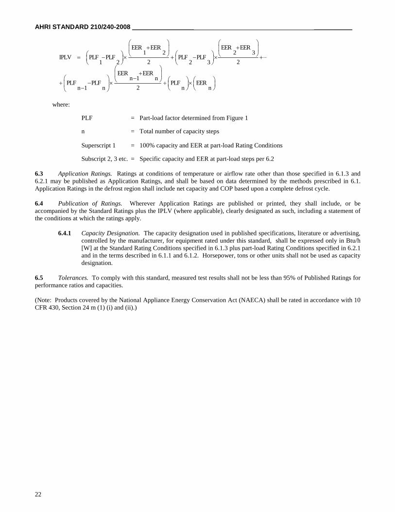
c. Use the following equation to calculate IPLV:
AHRI STANDARD 210/240-2008 _____________________ _____________
22
EER EER EER EER1 2 2 3
IPLV PLF PLF PLF PLF2 21 2 2 3
EER EERn 1 n
PLF PLF PLF EER2n 1 n n n
where:
PLF = Part-load factor determined from Figure 1
n = Total number of capacity steps
Superscript 1 = 100% capacity and EER at part-load Rating Conditions
Subscript 2, 3 etc. = Specific capacity and EER at part-load steps per 6.2
6.3 Application Ratings. Ratings at conditions of temperature or airflow rate other than those specified in 6.1.3 and6.2.1 may be published as Application Ratings, and shall be based on data determined by the methods prescribed in 6.1.Application Ratings in the defrost region shall include net capacity and COP based upon a complete defrost cycle.
6.4 Publication of Ratings. Wherever Application Ratings are published or printed, they shall include, or beaccompanied by the Standard Ratings plus the IPLV (where applicable), clearly designated as such, including a statement ofthe conditions at which the ratings apply.
6.4.1 Capacity Designation. The capacity designation used in published specifications, literature or advertising,controlled by the manufacturer, for equipment rated under this standard, shall be expressed only in Btu/h[W] at the Standard Rating Conditions specified in 6.1.3 plus part-load Rating Conditions specified in 6.2.1and in the terms described in 6.1.1 and 6.1.2. Horsepower, tons or other units shall not be used as capacitydesignation.
6.5 Tolerances. To comply with this standard, measured test results shall not be less than 95% of Published Ratings forperformance ratios and capacities.
(Note: Products covered by the National Appliance Energy Conservation Act (NAECA) shall be rated in accordance with 10CFR 430, Section 24 m (1) (i) and (ii).)
__________________ _______________ AHRI STANDARD 210/240-2008
23
AHRI STANDARD 210/240-2008 _____________________ _____________
24
Section 7. Minimum Data Requirements for Published Ratings
7.1 Minimum Data Requirements For Published Ratings. As a minimum, Published Ratings shall consist of thefollowing information:
a. For Unitary Air-Conditioners (air-cooled)
1. AHRI standard rating cooling capacity2. Seasonal Energy Efficiency Ratio, SEER
b. For Unitary Air-Conditioners (water-cooled and evaporative-cooled)
1. AHRI standard rating cooling capacity2. Energy Efficiency Ratio, EER
c. For all Air-Source Unitary Heat Pumps
1. AHRI standard rating cooling capacity2. Seasonal Energy Efficiency Ratio, SEER3. High temperature heating standard rating capacity4. Region IV Heating Seasonal Performance Factor, HSPF, minimum design heating requirement
7.2 Latent Capacity Designation. The moisture removal designation shall be published in the manufacturer’sspecifications and literature. The value shall be expressed consistently in either gross or net in one or more of the followingforms:
a. Sensible capacity/total capacity ratio and total capacityb. Latent capacity and total capacityc. Sensible capacity and total capacity
7.3 Rating Claims. All claims to ratings within the scope of this standard shall include the statement “Rated inaccordance with AHRI Standard 210/240”. All claims to ratings outside the scope of this standard shall include thestatement: “Outside the scope of AHRI Standard 210/240”. Wherever Application Ratings are published or printed, they shallinclude a statement of the conditions at which the ratings apply.
Section 8. Operating Requirements
8.1 Operating Requirements. Unitary equipment shall comply with the provisions of this section such that anyproduction unit will meet the requirements detailed herein.
8.2 Maximum Operating Conditions Test. Unitary equipment shall pass the following maximum operating conditionstest with an indoor-coil airflow rate as determined under 6.1.3.3.
8.2.1 Temperature Conditions. Temperature conditions shall be maintained as shown in Tables 12 or 13.
__________________ _______________ AHRI STANDARD 210/240-2008
25
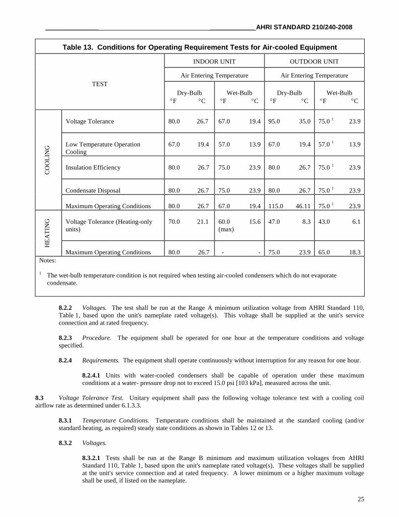
Table 13. Conditions for Operating Requirement Tests for Air-cooled Equipment
TEST
INDOOR UNIT OUTDOOR UNIT
Air Entering Temperature Air Entering Temperature
Dry-BulbF C
Wet-BulbF C
Dry-BulbF C
Wet-BulbF C
CO
OL
ING
Voltage Tolerance 80.0 26.7 67.0 19.4 95.0 35.0 75.0 1 23.9
Low Temperature OperationCooling
67.0 19.4 57.0 13.9 67.0 19.4 57.0 1 13.9
Insulation Efficiency 80.0 26.7 75.0 23.9 80.0 26.7 75.0 1 23.9
Condensate Disposal 80.0 26.7 75.0 23.9 80.0 26.7 75.0 1 23.9
Maximum Operating Conditions 80.0 26.7 67.0 19.4 115.0 46.11 75.0 1 23.9
HE
AT
ING Voltage Tolerance (Heating-only
units)70.0 21.1 60.0 15.6
(max)47.0 8.3 43.0 6.1
Maximum Operating Conditions 80.0 26.7 - - 75.0 23.9 65.0 18.3Notes:
1 The wet-bulb temperature condition is not required when testing air-cooled condensers which do not evaporatecondensate.
8.2.2 Voltages. The test shall be run at the Range A minimum utilization voltage from AHRI Standard 110,Table 1, based upon the unit's nameplate rated voltage(s). This voltage shall be supplied at the unit's serviceconnection and at rated frequency.
8.2.3 Procedure. The equipment shall be operated for one hour at the temperature conditions and voltagespecified.
8.2.4 Requirements. The equipment shall operate continuously without interruption for any reason for one hour.
8.2.4.1 Units with water-cooled condensers shall be capable of operation under these maximumconditions at a water- pressure drop not to exceed 15.0 psi [103 kPa], measured across the unit.
8.3 Voltage Tolerance Test. Unitary equipment shall pass the following voltage tolerance test with a cooling coilairflow rate as determined under 6.1.3.3.
8.3.1 Temperature Conditions. Temperature conditions shall be maintained at the standard cooling (and/orstandard heating, as required) steady state conditions as shown in Tables 12 or 13.
8.3.2 Voltages.
8.3.2.1 Tests shall be run at the Range B minimum and maximum utilization voltages from AHRIStandard 110, Table 1, based upon the unit's nameplate rated voltage(s). These voltages shall be suppliedat the unit's service connection and at rated frequency. A lower minimum or a higher maximum voltageshall be used, if listed on the nameplate.
AHRI STANDARD 210/240-2008 _____________________ _____________
26
8.3.2.2 The power supplied to single phase equipment shall be adjusted just prior to the shut-down period(8.3.3.2) so that the resulting voltage at the unit's service connection is 86% of nameplate rated voltagewhen the compressor motor is on locked-rotor. (For 200V or 208V nameplate rated equipment the restartvoltage shall be set at 180V when the compressor motor is on locked rotor). Open circuit voltage for three-phase equipment shall not be greater than 90% of nameplate rated voltage.
8.3.2.3 Within one minute after the equipment has resumed continuous operation (8.3.4.3), the voltageshall be restored to the values specified in 8.3.2.1.
8.3.3 Procedure.
8.3.3.1 The equipment shall be operated for one hour at the temperature conditions and voltage(s)specified.
8.3.3.2 All power to the equipment shall be shut off for a period sufficient to cause the compressor to stop(not to exceed five seconds) and then restored.
8.3.4 Requirements.
8.3.4.1 During both tests, the equipment shall operate without failure of any of its parts.
8.3.4.2 The equipment shall operate continuously without interruption for any reason for the one hourperiod preceding the power interruption.
8.3.4.3 The unit shall resume continuous operation within two hours of restoration of power and shall thenoperate continuously for one half hour. Operation and resetting of safety devices prior to establishment ofcontinuous operation is permitted.
8.4 Low-Temperature Operation Test (Cooling) (Not Required For Heating-only Units). Unitary equipment shall passthe following low-temperature operation test when operating with initial airflow rates as determined in 6.1.3.3 and 6.1.3.4and with controls and dampers set to produce the maximum tendency to frost or ice the evaporator, provided such settings arenot contrary to the manufacturer's instructions to the user.
8.4.1 Temperature Conditions. Temperature Conditions shall be maintained as shown in Table 12 or Table 13.
8.4.2 Procedure. The test shall be continuous with the unit on the cooling cycle, for not less than four hours afterestablishment of the specified temperature conditions. The unit will be permitted to start and stop under control ofan automatic limit device, if provided.
8.4.3 Requirements.
8.4.3.1 During the entire test, the equipment shall operate without damage or failure of any of its parts.
8.4.3.2 During the entire test, the air quantity shall not drop more than 25% from that determined underthe Standard Rating test.
8.4.3.3 During the test and during the defrosting period after the completion of the test, all ice or meltagemust be caught and removed by the drain provisions.
__________________ _______________ AHRI STANDARD 210/240-2008
27
8.5 Insulation Effectiveness Test (Cooling) (not required for heating-only units). Unitary equipment shall pass thefollowing insulation effectiveness test when operating with airflow rates as determined in 6.1.3.3 and 6.1.3.4 with controls,fans, dampers, and grilles set to produce the maximum tendency to sweat, provided such settings are not contrary to themanufacturer's instructions to the user.
8.5.1 Temperature Conditions. Temperature conditions shall be maintained as shown in Table 12 or Table 13.
8.5.2 Procedure. After establishment of the specified temperature conditions, the unit shall be operatedcontinuously for a period of four hours.
8.5.3 Requirements. During the test, no condensed water shall drop, run, or blow off from the unit casing.
8.6 Condensate Disposal Test (Cooling)* (not required for heating-only units). Unitary equipment which rejectscondensate to the condenser air shall pass the following condensate disposal test when operating with airflow rates asdetermined in 6.1.3.3 and 6.1.3.4 and with controls and dampers set to produce condensate at the maximum rate, providedsuch settings are not contrary to the manufacturer's instructions to the user.
* This test may be run concurrently with the Insulation Effectiveness Test (8.5).
8.6.1 Temperature Conditions. Temperature conditions shall be maintained as shown in Table 12 or Table 13.
8.6.2 Procedure. After establishment of the specified temperature conditions, the equipment shall be started withits condensate collection pan filled to the overflowing point and shall be operated continuously for four hours afterthe condensate level has reached equilibrium.
8.6.3 Requirements. During the test, there shall be no dripping, running-off, or blowing-off of moisture from theunit casing.
8.7 Tolerances. The conditions for the tests outlined in Section 8 are average values subject to tolerances of ± 1.0F [±0.6C] for air wet-bulb and dry-bulb temperatures and ± 1.0% of the reading for voltages.
Section 9. Marking and Nameplate Data
9.1 Marking and Nameplate Data. As a minimum, the nameplate shall display the manufacturer's name, modeldesignation, and electrical characteristics.
Nameplate voltages for 60 Hertz systems shall include one or more of the equipment nameplate voltage ratings shown inTable 1 of AHRI Standard 110. Nameplate voltages for 50 Hertz systems shall include one or more of the utilizationvoltages shown in Table 1 of IEC Standard 60038.
Section 10. Conformance Conditions
10.1 Conformance. While conformance with this standard is voluntary, conformance shall not be claimed or implied forproducts or equipment within the standard’s Purpose (Section 1) and Scope (Section 2) unless such product claims meet allof the requirements of the standard and all of the testing and rating requirements are measured and reported in completecompliance with the standard. Any product that has not met all the requirements of the standard shall not reference, state, oracknowledge the standard in any written, oral, or electronic communication.
AHRI STANDARD 210/240-2008
28
APPENDIX A. REFERENCES – NORMATIVE
A1 Listed here are all standards, handbooks and other publications essential to the formation and implementation of thestandard. All references in this appendix are considered as part of this standard.
A1.1 ANSI/ASHRAE Standard 37-2005, Methods of Testing for Rating Unitary Air-Conditioning and HeatPump Equipment, 2005, American Society of Heating, Refrigerating and Air-Conditioning Engineers, Inc., 1791Tullie Circle N.E., Atlanta, GA 30329, U.S.A.
A1.2 ANSI/ASHRAE Standard 41.1-1986 (RA 2006), Standard Method for Temperature Measurement, 2006,American Society of Heating, Refrigerating and Air-Conditioning Engineers, Inc., 1791 Tullie Circle, N.E., Atlanta,GA 30329, U.S.A.
A1.3 ANSI/ASHRAE Standard 51-1999/AMCA Standard 210-1999, Laboratory Methods of Testing Fans forAerodynamic Performance Rating, 1999, American Society of Heating, Refrigerating and Air-ConditioningEngineers, Inc., 1791 Tullie Circle, N.E., Atlanta, GA 30329, U.S.A.
A1.4 AHRI Standard 110-2002 (formerly ARI Standard 110-2002), Air-Conditioning and RefrigeratingEquipment Nameplate Voltages, Air-Conditioning, Heating, and Refrigeration Institute, 2002, 2111 WilsonBoulevard, Suite 500, Arlington, VA 22201, U.S.A.
A1.5 AHRI Standard 210/240-2003 (formerly ARI Standard 210/240-2003), Unitary Air-Conditioning and Air-Source Heat Pump Equipment, 2003, Air-Conditioning, Heating, and Refrigeration Institute, 2111 WilsonBoulevard, Suite 500, Arlington, VA 22201, U.S.A.
A1.6 AHRI Standard 210/240-2006 (formerly ARI Standard 210/240-2006), Unitary Air-Conditioning and Air-Source Heat Pump Equipment, 2006, Air-Conditioning, Heating, and Refrigeration Institute, 2111 WilsonBoulevard, Suite 500, Arlington, VA 22201, U.S.A.
A1.7 AHRI Standard 340/360-2007 (formerly ARI Standard 340/360-2007), Commercial and Industrial UnitaryAir-Conditioning and Heat Pump Equipment, 2004, Air-Conditioning, Heating, and Refrigeration Institute, 2111Wilson Boulevard, Suite 500, Arlington, VA 22201, U.S.A.
A1.8 ASHRAE Standard 23-1993, Methods of Testing for Rating Positive Displacement RefrigerantCompressors and Condensing Units, 1993, American Society of Heating, Refrigerating and Air-ConditioningEngineers, Inc., 1791 Tullie Circle, N.E., Atlanta, GA 30329, U.S.A.
A1.9 ASHRAE Standard 37-1988, Methods of Testing for Rating Unitary Air-Conditioning and Heat PumpEquipment, 1988, American Society of Heating, Refrigerating and Air-Conditioning Engineers, Inc., 1791 TullieCircle, N.E., Atlanta, GA 30329, U.S.A.
A1.10 ASHRAE Standard 41.2-1987 (RA 1992), Standard Methods for Laboratory Airflow Measurement, 1992,American Society of Heating, Refrigerating and Air-Conditioning Engineers, Inc., 1791 Tullie Circle, N.E., Atlanta,GA 30329, U.S.A.
A1.11 ASHRAE Standard 41.6-1994 (RA 2001), Method for Measurement of Moist Air Properties, 2001,American Society of Heating, Refrigerating and Air-Conditioning Engineers, Inc., 1791 Tullie Circle, N.E., Atlanta,GA 30329, U.S.A.
A1.12 ASHRAE Standard 41.9-2000, Calorimeter Test Methods for Mass Flow Measurements of VolatileRefrigerants, 2000, American Society of Heating, Refrigerating and Air-Conditioning Engineers, Inc., 1791 TullieCircle, N.E., Atlanta, GA 30329, U.S.A.
A1.13 ASHRAE Terminology of Heating, Ventilation, Air-Conditioning and Refrigeration, Second Edition, 1991,American Society of Heating, Refrigerating and Air-Conditioning Engineers, Inc., 1791 Tullie Circle, N.E., Atlanta,GA 30329, U.S.A.
AHRI STANDARD 210/240-2008
29
A1.14 IEC Standard 60038, IEC Standard Voltages, 2002, International Electrotechnical Commission, 3, rue deVarembe, P.O. Box 131, 1211 Geneva 20, Switzerland.
A1.15 Title 10, Code of Federal Regulations (CFR), Part 430, Subparts 430.2 and 430.32 (c), U.S. NationalArchives and Records Administration, 8601 Adelphi Road, College Park, MD 20740-6001.
APPENDIX B. REFERENCES – INFORMATIVE
B1 Listed here are standards, handbooks and other publications which may provide useful information and backgroundbut are not considered essential. References in this appendix are not considered part of the standard.
B1.1 ANSI/ASHRAE Standard 116-1995 (RA 05), Methods of Testing for Rating for Seasonal Efficiency ofUnitary Air Conditioners and Heat Pumps, 2005, American Society of Heating, Refrigerating and Air-ConditioningEngineers, Inc., 1791 Tullie Circle, N.E., Atlanta, GA 30329, U.S.A.
AHRI STANDARD 210/240-2008
30
APPENDIX C. UNIFORM TEST METHOD FOR MEASURINGTHE ENERGY CONSUMPTION OF CENTRAL AIR
CONDITIONERS AND HEAT PUMPS – NORMATIVE
Foreword: This appendix to AHRI Standard 210/240-2008 is the “Uniform Test Method for Measuring the EnergyConsumption of Central Air Conditioners and Heat Pumps” Appendix M to Subpart B of Part 430, pages 59135through 59180, Federal Register, Vol. 70, No. 195, Tuesday, October 11, 2005 as amended by the Federal Register,Vol. 72, No. 203, Monday, October 22, 2007 pages 59906 through 59934.
APPENDIX M to Subpart B of Part 430 – Uniform TestMethod for Measuring the Energy Consumption of Central
Air Conditioners and Heat Pumps
Electronic Code of Federal Regulations (e-CFR)
BETA TEST SITE
e-CFR Data is current as of February 9, 2006
Amendment from October 11, 2005
10 CFR--PART 430
Amendment(s) published October 11, 2005, in 70 FR 59135
Effective Date(s): April 10, 2006
5. Appendix M to Subpart B is revised to read as follows:
Appendix M to Subpart B of Part 430—Uniform Test Method for Measuring the Energy Consumption of CentralAir Conditioners and Heat Pumps
AHRI STANDARD 210/240-2008
31
1. DEFINITIONS
2. TESTING CONDITIONS
2.1 Test room requirements.
2.2 Test unit installation requirements.
2.2.1 Defrost control settings.
2.2.2 Special requirements for units having a multiple-speed outdoor fan.
2.2.3 Special requirements for multi-split air conditioners and heat pumps, and systems composed of multiple mini-splitunits (outdoor units located side-by-side) that would normally operate using two or more indoor thermostats.
2.2.4 Wet-bulb temperature requirements for the air entering the indoor and outdoor coils.
2.2.4.1 Cooling mode tests.
2.2.4.2 Heating mode tests.
2.2.5 Additional refrigerant charging requirements.
2.3 Indoor air volume rates.
2.3.1 Cooling tests.
2.3.2 Heating tests.
2.4 Indoor coil inlet and outlet duct connections.
2.4.1 Outlet plenum for the indoor unit.
2.4.2 Inlet plenum for the indoor unit.
2.5 Indoor coil air property measurements and air damper box applications.
2.5.1 Test set-up on the inlet side of the indoor coil: For cases where the inlet damper box is installed.
2.5.1.1 If the section 2.4.2 inlet plenum is installed.
2.5.1.2 If the section 2.4.2 inlet plenum is not installed.
2.5.2 Test set-up on the inlet side of the indoor unit: For cases where no inlet damper box is installed.
2.5.3 Indoor coil static pressure difference measurement.
2.5.4 Test set-up on the outlet side of the indoor coil.
2.5.4.1 Outlet air damper box placement and requirements.
2.5.4.2 Procedures to minimize temperature maldistribution.
2.5.4.3 Minimizing air leakage.
AHRI STANDARD 210/240-2008
32
2.5.5 Dry bulb temperature measurement.
2.5.6 Water vapor content measurement.
2.5.7 Air damper box performance requirements.
2.6 Airflow measuring apparatus.
2.7 Electrical voltage supply.
2.8 Electrical power and energy measurements.
2.9 Time measurements.
2.10 Test apparatus for the secondary space conditioning capacity measurement.
2.10.1 Outdoor Air Enthalpy Method.
2.10.2 Compressor Calibration Method.
2.10.3 Refrigerant Enthalpy Method.
2.11 Measurement of test room ambient conditions.
2.12 Measurement of indoor fan speed.
2.13 Measurement of barometric pressure.
3. TESTING PROCEDURES
3.1 General Requirements.
3.1.1 Primary and secondary test methods.
3.1.2 Manufacturer-provided equipment overrides.
3.1.3 Airflow through the outdoor coil.
3.1.4 Airflow through the indoor coil.
3.1.4.1 Cooling Full-Load Air Volume Rate.
3.1.4.1.1 Cooling Full-Load Air Volume Rate for Ducted Units.
3.1.4.1.2 Cooling Full-Load Air Volume Rate for Non-ducted Units.
3.1.4.2 Cooling Minimum Air Volume Rate.
3.1.4.3 Cooling Intermediate Air Volume Rate.
3.1.4.4 Heating Full-Load Air Volume Rate.
3.1.4.4.1 Ducted heat pumps where the Heating and Cooling Full-Load Air Volume Rates are the same.
AHRI STANDARD 210/240-2008
33
3.1.4.4.2 Ducted heat pumps where the Heating and Cooling Full-Load Air Volume Rates are different due to indoor fanoperation.
3.1.4.4.3 Ducted heating-only heat pumps.
3.1.4.4.4 Non-ducted heat pumps, including non-ducted heating-only heat pumps.
3.1.4.5 Heating Minimum Air Volume Rate.
3.1.4.6 Heating Intermediate Air Volume Rate.
3.1.4.7 Heating Nominal Air Volume Rate.
3.1.5 Indoor test room requirement when the air surrounding the indoor unit is not supplied from the same source as the airentering the indoor unit.
3.1.6 Air volume rate calculations.
3.1.7 Test sequence.
3.1.8 Requirement for the air temperature distribution leaving the indoor coil.
3.1.9 Control of auxiliary resistive heating elements.
3.2 Cooling mode tests for different types of air conditioners and heat pumps.
3.2.1 Tests for a unit having a single-speed compressor that is tested with a fixed-speed indoor fan installed, with a constant-air-volume-rate indoor fan installed, or with no indoor fan installed.
3.2.2 Tests for a unit having a single-speed compressor and a variable-speed variable-air-volume-rate indoor fan installed.
3.2.2.1 Indoor fan capacity modulation that correlates with the outdoor dry bulb temperature.
3.2.2.2 Indoor fan capacity modulation based on adjusting the sensible to total (S/T) cooling capacity ratio.
3.2.3 Tests for a unit having a two-capacity compressor.
3.2.4 Tests for a unit having a variable-speed compressor.
3.3 Test procedures for steady-state wet coil cooling mode tests (the A, A2, A1, B, B2, B1, EV, and F1 Tests).
3.4 Test procedures for the optional steady-state dry coil cooling mode tests (the C, C1, and G1 Tests).
3.5 Test procedures for the optional cyclic dry coil cooling mode tests (the D, D1, and I1 Tests).
3.5.1 Procedures when testing ducted systems.
3.5.2 Procedures when testing non-ducted systems.
3.5.3 Cooling mode cyclic degradation coefficient calculation.
3.6 Heating mode tests for different types of heat pumps, including heating-only heat pumps.
AHRI STANDARD 210/240-2008
34
3.6.1 Tests for a heat pump having a single-speed compressor that is tested with a fixed speed indoor fan installed, with aconstant-air-volume-rate indoor fan installed, or with no indoor fan installed.
3.6.2 Tests for a heat pump having a single-speed compressor and a variable-speed, variable-air-volume-rate indoor fan:capacity modulation correlates with outdoor dry bulb temperature.
3.6.3 Tests for a heat pump having a two-capacity compressor (see Definition 1.45), including two-capacity, northern heatpumps (see Definition 1.46).
3.6.4 Tests for a heat pump having a variable-speed compressor.
3.6.5 Additional test for a heat pump having a heat comfort controller.
3.7 Test procedures for steady-state Maximum Temperature and High Temperature heating mode tests (the H01, H1, H12,H11, and H1N Tests).
3.8 Test procedures for the optional cyclic heating mode tests (the H0C1, H1C, and H1C1 Tests).
3.8.1 Heating mode cyclic degradation coefficient calculation.
3.9 Test procedures for Frost Accumulation heating mode tests (the H2, H22, H2V, and H21 Tests).
3.9.1 Average space heating capacity and electrical power calculations.
3.9.2 Demand defrost credit.
3.10 Test procedures for steady-state Low Temperature heating mode tests (the H3, H32, and H31 Tests).
3.11 Additional requirements for the secondary test methods.
3.11.1 If using the Outdoor Air Enthalpy Method as the secondary test method.
3.11.1.1 If a preliminary test precedes the official test
3.11.1.2 If a preliminary test does not precede the official test.
3.11.1.3 Official test.
3.11.2 If using the Compressor Calibration Method as the secondary test method.
3.11.3 If using the Refrigerant Enthalpy Method as the secondary test method.
3.12 Rounding of space conditioning capacities for reporting purposes.
4. CALCULATIONS OF SEASONAL PERFORMANCE DESCRIPTORS
4.1 Seasonal Energy Efficiency Ratio (SEER) Calculations.
4.1.1 SEER calculations for an air conditioner or heat pump having a single-speed compressor that was tested with a fixed-speed indoor fan installed, a constant-air-volume-rate indoor fan installed, or with no indoor fan installed.
4.1.2 SEER calculations for an air conditioner or heat pump having a single-speed compressor and a variable-speedvariable-air-volume-rate indoor fan.
AHRI STANDARD 210/240-2008
35
4.1.2.1 Units covered by section 3.2.2.1 where indoor fan capacity modulation correlates with the outdoor dry bulbtemperature.
4.1.2.2 Units covered by section 3.2.2.2 where indoor fan capacity modulation is used to adjust the sensible to total coolingcapacity ratio.
4.1.3 SEER calculations for an air conditioner or heat pump having a two-capacity compressor.
4.1.3.1 Steady-state space cooling capacity at low compressor capacity is greater than or equal to the building cooling load at
temperature Tj, Q
ck=1(Tj) ≥ BL(Tj).
4.1.3.2 Unit alternates between high (k=2) and low (k=1) compressor capacity to satisfy the building cooling load at
temperature Tj, Q
ck=1 (Tj) < BL(Tj) < Q
ck=2(Tj).
4.1.3.3 Unit only operates at high (k=2) compressor capacity at temperature Tj and its capacity is greater than the building
cooling load, BL(Tj) < Q
ck=2(Tj).
4.1.3.4 Unit must operate continuously at high (k=2) compressor capacity at temperature Tj, BL(Tj) ≥ Q
ck=2(Tj).
4.1.4 SEER calculations for an air conditioner or heat pump having a variable-speed compressor.
4.1.4.1 Steady-state space cooling capacity when operating at minimum compressor speed is greater than or equal to the
building cooling load at temperature Tj, Q
ck=1(Tj) ≥ BL(Tj).
4.1.4.2 Unit operates at an intermediate compressor speed (k=i) in order to match the building cooling load at temperature Tj,
Q
ck=1(Tj) < BL(Tj) < Q
ck=2(Tj).
4.1.4.3 Unit must operate continuously at maximum (k=2) compressor speed at temperature Tj, BL(Tj) ≥ Q
ck=2(Tj).
4.2 Heating Seasonal Performance Factor (HSPF) Calculations.
4.2.1 Additional steps for calculating the HSPF of a heat pump having a single-speed compressor that was tested with afixed-speed indoor fan installed, a constant-air-volume-rate indoor fan installed, or with no indoor fan installed.
4.2.2 Additional steps for calculating the HSPF of a heat pump having a single-speed compressor and a variable-speed,variable-air-volume-rate indoor fan.
4.2.3 Additional steps for calculating the HSPF of a heat pump having a two-capacity compressor.
4.2.3.1 Steady-state space heating capacity when operating at low compressor capacity is greater than or equal to the
building heating load at temperature Tj, Q
hk=1(Tj) ≥ BL(Tj).
4.2.3.2 Heat pump alternates between high (k=2) and low (k=1) compressor capacity to satisfy the building heating load at a
temperature Tj, Q
hk=1(Tj) BL (Tj) < Q
hk=2(Tj).
4.2.3.3 Heat pump only operates at high (k=2) compressor capacity at temperature Tj and its capacity is greater than the
building heating load, BL(Tj) < Q
hk=2(Tj).
4.2.3.4 Heat pump must operate continuously at high (k=2) compressor capacity at temperature Tj, BL(Tj) ≥ Q
hk=2(Tj).
AHRI STANDARD 210/240-2008
36
4.2.4 Additional steps for calculating the HSPF of a heat pump having a variable-speed compressor.
4.2.4.1 Steady-state space heating capacity when operating at minimum compressor speed is greater than or equal to the
building heating load at temperature Tj, Q
hk=1(Tj) ≥ BL(Tj).
4.2.4.2 Heat pump operates at an intermediate compressor speed (k=i) in order to match the building heating load at a
temperature Tj, Q
hk=1(Tj) < BL(Tj) < Q
hk=2(Tj).
4.2.4.3 Heat pump must operate continuously at maximum (k=2) compressor speed at temperature Tj, BL(Tj) ≥ Q
hk=2(Tj).
4.2.5 Heat pumps having a heat comfort controller.
4.2.5.1 Heat pump having a heat comfort controller: Additional steps for calculating the HSPF of a heat pump having asingle-speed compressor that was tested with a fixed-speed indoor fan installed, a constant-air-volume-rate indoor faninstalled, or with no indoor fan installed.
4.2.5.2 Heat pump having a heat comfort controller: Additional steps for calculating the HSPF of a heat pump having asingle-speed compressor and a variable-speed, variable-air-volume-rate indoor fan.
4.2.5.3 Heat pumps having a heat comfort controller: Additional steps for calculating the HSPF of a heat pump having a two-capacity compressor.
4.2.5.4 Heat pumps having a heat comfort controller: Additional steps for calculating the HSPF of a heat pump having avariable-speed compressor. [Reserved]
4.3 Calculations of the Actual and Representative Regional Annual Performance Factors for Heat Pumps.
4.3.1 Calculation of actual regional annual performance factors (APFA) for a particular location and for each standardizeddesign heating requirement.
4.3.2 Calculation of representative regional annual performance factors (APFR) for each generalized climatic region and foreach standardized design heating requirement.
4.4 Rounding of SEER, HSPF, and APF for reporting purposes.
1. Definitions
1.1 Annual performance factor means the total heating and cooling done by a heat pump in a particular region in one yeardivided by the total electric energy used in one year. Paragraph (m)(3)(iii) of §430.23 of the Code of Federal Regulationsstates the calculation requirements for this rating descriptor.
1.2 AHRI means Air-Conditioning and Refrigeration Institute.
1.3 AHRI Standard 210/240–2006 means the test standard “Unitary Air-Conditioning and Air-Source Heat PumpEquipment” published in 2006 by AHRI.
1.4 ASHRAE means the American Society of Heating, Refrigerating and Air-Conditioning Engineers, Inc.
1.5 ASHRAE Standard 23–2005 means the test standard “Methods of Testing for Rating Positive DisplacementRefrigerant Compressors and Condensing Units” published in 2005 by ASHRAE.
1.6 ASHRAE Standard 37–2005 means the test standard “Methods of Testing for Rating Unitary Air-Conditioning andHeat Pump Equipment” published in 2005 by ASHRAE.
AHRI STANDARD 210/240-2008
37
1.7 ASHRAE Standard 41.1–86 (RA 01) means the test standard “Standard Method for Temperature Measurement”published in 1986 and reaffirmed in 2001 by ASHRAE.
1.8 ASHRAE Standard 41.2–87 (RA 92) means the test standard “Standard Methods for Laboratory AirflowMeasurement” published in 1987 and reaffirmed in 1992 by ASHRAE.
1.9 ASHRAE Standard 41.6–94 (RA 01) means the test standard “Method for Measurement of Moist Air Properties”published in 1994 and reaffirmed in 2001 by ASHRAE.
1.10 ASHRAE Standard 41.9–00 means the test standard “Calorimeter Test Methods for Mass Flow Measurements ofVolatile Refrigerants” published in 2000 by ASHRAE.
1.11 ASHRAE Standard 51–99/AMCA Standard 210–1999 means the test standard “Laboratory Methods of Testing Fansfor Aerodynamic Performance Rating” published in 1999 by ASHRAE and the Air Movement and Control AssociationInternational, Inc.
1.12 ASHRAE Standard 116–95 (RA05) means the test standard “Methods of Testing for Rating for Seasonal Efficiency ofUnitary Air Conditioners and Heat Pumps” published in 1995 and reaffirmed in 2005 by ASHRAE.
1.13 CFR means Code of Federal Regulations.
1.14 Constant-air-volume-rate indoor fan means a fan that varies its operating speed to provide a fixed air-volume-rate froma ducted system.
1.15 Continuously recorded, when referring to a dry bulb measurement, means that the specified temperature must besampled at regular intervals that are equal to or less than the maximum intervals specified in section 4.3 part “a” of ASHRAEStandard 41.1–86 (RA 01). If such dry bulb temperatures are used only for test room control, it means that one samples atregular intervals equal to or less than the maximum intervals specified in section 4.3 part “b” of the same ASHRAE Standard.Regarding wet bulb temperature, dew point temperature, or relative humidity measurements, continuously recorded meansthat the measurements must be made at regular intervals that are equal to or less than 1 minute.
1.16 Cooling load factor (CLF) means the ratio having as its numerator the total cooling delivered during a cyclic operatinginterval consisting of one ON period and one OFF period. The denominator is the total cooling that would be delivered, giventhe same ambient conditions, had the unit operated continuously at its steady-state space cooling capacity for the same totaltime (ON + OFF) interval.
1.17 Coefficient of Performance (COP) means the ratio of the average rate of space heating delivered to the average rate ofelectrical energy consumed by the heat pump. These rate quantities must be determined from a single test or, if derived viainterpolation, must be tied to a single set of operating conditions. COP is a dimensionless quantity. When determined for aducted unit tested without an indoor fan installed, COP must include the section 3.7, 3.8, and 3.9.1 default values for the heatoutput and power input of a fan motor.
1.18 Cyclic Test means a test where the unit's compressor is cycled on and off for specific time intervals. A cyclic testprovides half the information needed to calculate a degradation coefficient.
1.19 Damper box means a short section of duct having an air damper that meets the performance requirements of section2.5.7.
1.20 Degradation coefficient (CD) means a parameter used in calculating the part load factor. The degradation coefficientfor cooling is denoted by CD
c . The degradation coefficient for heating is denoted by CDh .
1.21 Demand-defrost control system means a system that defrosts the heat pump outdoor coil only when measuring apredetermined degradation of performance. The heat pump's controls monitor one or more parameters that always vary withthe amount of frost accumulated on the outdoor coil (e.g., coil to air differential temperature, coil differential air pressure,outdoor fan power or current, optical sensors, etc.) at least once for every ten minutes of compressor ON-time when spaceheating. One acceptable alternative to the criterion given in the prior sentence is a feedback system that measures the lengthof the defrost period and adjusts defrost frequency accordingly. 1 In all cases, when the frost parameter(s) reaches a
AHRI STANDARD 210/240-2008
38
predetermined value, the system initiates a defrost. In a demand-defrost control system, defrosts are terminated based onmonitoring a parameter(s) that indicates that frost has been eliminated from the coil.
1 Systems that vary defrost intervals according to outdoor dry-bulb temperature are not demand defrost systems.
A demand-defrost control system, which otherwise meets the above requirements, may allow time-initiated defrosts if, andonly if, such defrosts occur after 6 hours of compressor operating time.
1.22 Design heating requirement (DHR) predicts the space heating load of a residence when subjected to outdoor designconditions. Estimates for the minimum and maximum DHR are provided for six generalized U.S. climatic regions in section4.2.
1.23 Dry-coil tests are cooling mode tests where the wet-bulb temperature of the air supplied to the indoor coil ismaintained low enough that no condensate forms on this coil.
1.24 Ducted system means an air conditioner or heat pump that is designed to be permanently installed equipment anddelivers conditioned air to the indoor space through a duct(s). The air conditioner or heat pump may be either a split systemor a single-packaged unit.
1.25 Energy efficiency ratio (EER) means the ratio of the average rate of space cooling delivered to the average rate ofelectrical energy consumed by the air conditioner or heat pump. These rate quantities must be determined from a single testor, if derived via interpolation, must be tied to a single set of operating conditions. EER is expressed in units of
Btu/h
W
When determined for a ducted unit tested without an indoor fan installed, EER must include the section 3.3 and 3.5.1 defaultvalues for the heat output and power input of a fan motor.
1.26 Heating load factor (HLF) means the ratio having as its numerator the total heating delivered during a cyclic operatinginterval consisting of one ON period and one OFF period. The denominator is the total heating that would be delivered, giventhe same ambient conditions, if the unit operated continuously at its steady-state space heating capacity for the same totaltime (ON plus OFF) interval.
1.27 Heating seasonal performance factor (HSPF) means the total space heating required during the space heating season,expressed in Btu's, divided by the total electrical energy consumed by the heat pump system during the same season,expressed in watt-hours. The HSPF used to evaluate compliance with the Energy Conservation Standards (see 10 CFR430.32(c), Subpart C) is based on Region IV, the minimum standardized design heating requirement, and the sampling planstated in 10 CFR 430.24(m), Subpart B.
1.28 Heat pump having a heat comfort controller means equipment that regulates the operation of the electric resistanceelements to assure that the air temperature leaving the indoor section does not fall below a specified temperature. Thisspecified temperature is usually field adjustable. Heat pumps that actively regulate the rate of electric resistance heating whenoperating below the balance point (as the result of a second stage call from the thermostat) but do not operate to maintain aminimum delivery temperature are not considered as having a heat comfort controller.
1.29 Mini-split air conditioners and heat pumps means systems that have a single outdoor section and one or more indoorsections. The indoor sections cycle on and off in unison in response to a single indoor thermostat.
1.30 Multiple-split air conditioners and heat pumps means systems that have two or more indoor sections. The indoorsections operate independently and can be used to condition multiple zones in response to multiple indoor thermostats.
1.31 Non-ducted system means an air conditioner or heat pump that is designed to be permanently installed equipment anddirectly heats or cools air within the conditioned space using one or more indoor coils that are mounted on room walls and/orceilings. The unit may be of a modular design that allows for combining multiple outdoor coils and compressors to create oneoverall system. Non-ducted systems covered by this test procedure are all split systems.
AHRI STANDARD 210/240-2008
39
1.32 Part-load factor (PLF) means the ratio of the cyclic energy efficiency ratio (coefficient of performance) to the steady-state energy efficiency ratio (coefficient of performance). Evaluate both energy efficiency ratios (coefficients of performance)based on operation at the same ambient conditions.
1.33 Seasonal energy efficiency ratio (SEER) means the total heat removed from the conditioned space during the annualcooling season, expressed in Btu's, divided by the total electrical energy consumed by the air conditioner or heat pump duringthe same season, expressed in watt-hours. The SEER calculation in section 4.1 of this Appendix and the sampling plan statedin 10 CFR Subpart B, 430.24(m) are used to evaluate compliance with the Energy Conservation Standards. (See 10 CFR430.32(c), Subpart C.)
1.34 Single-packaged unit means any central air conditioner or heat pump that has all major assemblies enclosed in onecabinet.
1.35 Small-duct, high-velocity system means a system that contains a blower and indoor coil combination that is designedfor, and produces, at least 1.2 inches (of water) of external static pressure when operated at the full-load air volume rate of220–350 cfm per rated ton of cooling. When applied in the field, small-duct products use high-velocity room outlets (i.e.,generally greater than 1000 fpm) having less than 6.0 square inches of free area.
1.36 Split system means any air conditioner or heat pump that has one or more of the major assemblies separated from theothers.
1.37 Standard air means dry air having a mass density of 0.075 lb/ft3.
1.38 Steady-state test means a test where the test conditions are regulated to remain as constant as possible while the unitoperates continuously in the same mode.
1.39 Temperature bin means the 5 °F increments that are used to partition the outdoor dry-bulb temperature ranges of thecooling (≥ 65 °F) and heating (<65 °F) seasons.
1.40 Test condition tolerance means the maximum permissible difference between the average value of the measured testparameter and the specified test condition.
1.41 Test operating tolerance means the maximum permissible range that a measurement may vary over the specified testinterval. The difference between the maximum and minimum sampled values must be less than or equal to the specified testoperating tolerance.
1.42 Time adaptive defrost control system is a demand-defrost control system (see definition 1.21) that measures the lengthof the prior defrost period(s) and uses that information to automatically determine when to initiate the next defrost cycle.
1.43 Time-temperature defrost control systems initiate or evaluate initiating a defrost cycle only when a predeterminedcumulative compressor ON-time is obtained. This predetermined ON-time is generally a fixed value (e.g., 30, 45, 90minutes) although it may vary based on the measured outdoor dry-bulb temperature. The ON-time counter accumulates ifcontroller measurements (e.g., outdoor temperature, evaporator temperature) indicate that frost formation conditions arepresent, and it is reset/remains at zero at all other times. In one application of the control scheme, a defrost is initiatedwhenever the counter time equals the predetermined ON-time. The counter is reset when the defrost cycle is completed.
In a second application of the control scheme, one or more parameters are measured (e.g., air and/or refrigerant temperatures)at the predetermined, cumulative, compressor ON-time. A defrost is initiated only if the measured parameter(s) falls within apredetermined range. The ON-time counter is reset regardless of whether a defrost is initiated. If systems of this second typeuse cumulative ON-time intervals of 10 minutes or less, then the heat pump may qualify as having a demand defrost controlsystem (see definition 1.21).
1.44 Triple-split system means an air conditioner or heat pump that is composed of three separate components: An outdoorfan coil section, an indoor fan coil section, and an indoor compressor section.
1.45 Two-capacity (or two-stage) compressor means an air conditioner or heat pump that has one of the following:
AHRI STANDARD 210/240-2008
40
(1) A two-speed compressor,
(2) Two compressors where only one compressor ever operates at a time,
(3) Two compressors where one compressor (Compressor #1) operates at low loads and both compressors (Compressors #1and #2) operate at high loads but Compressor #2 never operates alone, or
(4) A compressor that is capable of cylinder or scroll unloading.
For such systems, low capacity means:
(1) Operating at low compressor speed,
(2) Operating the lower capacity compressor,
(3) Operating Compressor #1, or
(4) Operating with the compressor unloaded (e.g., operating one piston of a two-piston reciprocating compressor, using afixed fractional volume of the full scroll, etc.).
For such systems, high capacity means:
(1) Operating at high compressor speed,
(2) Operating the higher capacity compressor,
(3) Operating Compressors #1 and #2, or
(4) Operating with the compressor loaded (e.g., operating both pistons of a two-piston reciprocating compressor, using thefull volume of the scroll).
1.46 Two-capacity, northern heat pump means a heat pump that has a factory or field-selectable lock-out feature to preventspace cooling at high-capacity. Two-capacity heat pumps having this feature will typically have two sets of ratings, one withthe feature disabled and one with the feature enabled. The indoor coil model number should reflect whether the ratingspertain to the lockout enabled option via the inclusion of an extra identifier, such as “+LO.” When testing as a two-capacity,northern heat pump, the lockout feature must remain enabled for all tests.
1.47 Wet-coil test means a test conducted at test conditions that typically cause water vapor to condense on the test unitevaporator coil.
2. Testing Conditions
This test procedure covers split-type and single-packaged ducted units and split-type non-ducted units. Except for unitshaving a variable-speed compressor, ducted units tested without an indoor fan installed are covered.
a. Only a subset of the sections listed in this test procedure apply when testing and rating a particular unit. Tables 1–Athrough 1–C show which sections of the test procedure apply to each type of equipment. In each table, look at all four of theRoman numeral categories to see what test sections apply to the equipment being tested.
1. The first category, Rows I–1 through I–4 of the Tables, pertains to the compressor and indoor fan features of theequipment. After identifying the correct “I” row, find the table cells in the same row that list the type of equipment beingtested: Air conditioner (AC), heat pump (HP), or heating-only heat pump (HH). Use the test section(s) listed above eachnoted table cell for testing and rating the unit.
AHRI STANDARD 210/240-2008
41
2. The second category, Rows II–1 and II–2, pertains to the presence or absence of ducts. Row II–1 shows the testprocedure sections that apply to ducted systems, and Row II–2 shows those that apply to non-ducted systems.
3. The third category is for special features that may be present in the equipment. When testing units that have one ormore of the three (special) equipment features described by the Table legend for Category III, use Row III to find testsections that apply.
4. The fourth category is for the secondary test method to be used. If the secondary method for determining the unit'scooling and/or heating capacity is known, use Row IV to find the appropriate test sections. Otherwise, include all of thetest sections referenced by Row IV cell entries—i.e., sections 2.10 to 2.10.3 and 3.11 to 3.11.3—among those sectionsconsulted for testing and rating information.
b. Obtain a complete listing of all pertinent test sections by recording those sections identified from the four categories above.
c. The user should note that, for many sections, only part of a section applies to the unit being tested. In a few cases, theentire section may not apply. For example, sections 3.4 to 3.5.3 (which describe optional dry coil tests), are not relevant if theallowed default value for the cooling mode cyclic degradation coefficient is used rather than determining it by testing.
Example for Using Tables 1–A to 1–C
Equipment Description: A ducted air conditioner having a single-speed compressor, a fixed-speed indoor fan, and a multi-speed outdoor fan.
Secondary Test Method: Refrigerant Enthalpy Method
Step 1. Determine which of four listed Row “I” options applies ==> Row I–2
Table 1–A: “AC” in Row I–2 is found in the columns for sections 1.1 to 1.47, 2.1 to 2.2, 2.2.4 to 2.2.4.1, 2.2.5, 2.3 to 2.3.1,2.4 to 2.4.1, 2.5, 2.5.2 to 2.10, and 2.11 to 2.13.
Table 1–B: “AC” is listed in Row I–2 for sections 3 to 3.1.4, 3.1.5 to 3.1.8, 3.2.1, 3.3 to 3.5, 3.5.3, 3.11 and 3.12.
Table 1–C: “AC” is listed in Row I–2 for sections 4.1.1 and 4.4.
Step 2. Equipment is ducted ==> Row II–1
Table 1–A: “AC” is listed in Row II–1 for sections 2.4.2 and 2.5.1 to 2.5.1.2.
Table 1–B: “AC” is listed in Row II–1 for sections 3.1.4.1 to 3.1.4.1.1 and 3.5.1.
Table 1–C: no “AC” listings in Row II–1.
Step 3. Equipment Special Features include multi-speed outdoor fan ==> Row III, M
Table 1–A: “M” is listed in Row III for section 2.2.2
Tables 1–B and 1–C: no “M” listings in Row III.
AHRI STANDARD 210/240-2008
42
Step 4. Secondary Test Method is Refrigerant Enthalpy Method ==> Row IV, R
Table 1–A: “R” is listed in Row IV for section 2.10.3
Table 1–B: “R” is listed in Row IV for section 3.11.3
Table 1–C: no “R” listings in Row IV.
Step 5. Cumulative listing of applicable test procedure sections 1.1 to 1.47, 2.1 to 2.2, 2.2.2, 2.2.4 to 2.4.1, 2.2.5, 2.3 to 2.3.1,2.4 to 2.4.1, 2.4.2, 2.5, 2.5.1 to 2.5.1.2, 2.5.2 to 2.10, 2.10.3, 2.11 to 2.13, 3. to 3.1.4, 3.1.4.1 to 3.1.4.1.1, 3.1.5 to 3.1.8, 3.2.1,3.3 to 3.5, 3.5.1, 3.5.3, 3.11, 3.11.3, 3.12, 4.1.1, and 4.4.
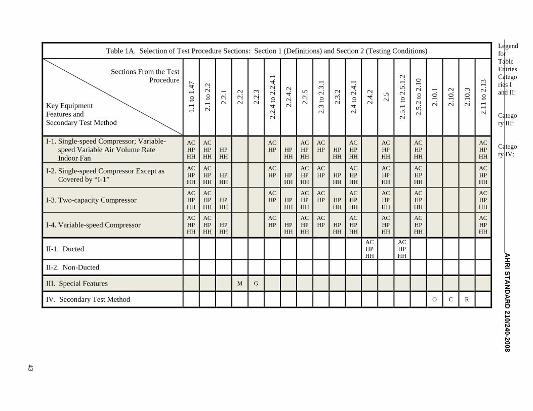
_
43
__
__
__
__
__
__
__
__
__
__
__
__
__
__
__
__
__
__
__
__
__
__
__
__
__
__
__
__
AH
RI
ST
AN
DA
RD
21
0/2
40
-20
08
LegendforTableEntriesCategories Iand II:
Category III:
Category IV:
Table 1A. Selection of Test Procedure Sections: Section 1 (Definitions) and Section 2 (Testing Conditions)
Sections From the TestProcedure
Key EquipmentFeatures andSecondary Test Method
1.1
to1.
47
2.1
to2.
2
2.2
.1
2.2
.2
2.2
.3
2.2
.4to
2.2
.4.1
2.2
.4.2
2.2
.5
2.3
to2.
3.1
2.3
.2
2.4
to2.
4.1
2.4
.2
2.5
2.5
.1to
2.5
.1.2
2.5
.2to
2.1
0
2.1
0.1
2.1
0.2
2.1
0.3
2.1
1to
2.1
3
I-1. Single-speed Compressor; Variable-speed Variable Air Volume RateIndoor Fan
ACHPHH
ACHPHH
HPHH
ACHP HP
HH
ACHPHH
ACHP HP
HH
ACHPHH
ACHPHH
ACHPHH
ACHPHH
I-2. Single-speed Compressor Except asCovered by “I-1”
ACHPHH
ACHPHH
HPHH
ACHP HP
HH
ACHPHH
ACHP HP
HH
ACHPHH
ACHPHH
ACHPHH
ACHPHH
I-3. Two-capacity CompressorACHPHH
ACHPHH
HPHH
ACHP HP
HH
ACHPHH
ACHP HP
HH
ACHPHH
ACHPHH
ACHPHH
ACHPHH
I-4. Variable-speed CompressorACHPHH
ACHPHH
HPHH
ACHP HP
HH
ACHPHH
ACHP HP
HH
ACHPHH
ACHPHH
ACHPHH
ACHPHH
II-1. DuctedACHPHH
ACHPHH
II-2. Non-Ducted
III. Special Features M G
IV. Secondary Test Method O C R
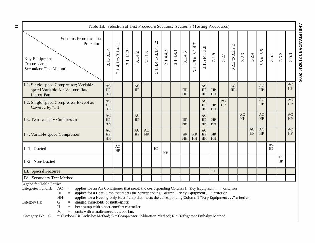
AH
RI
ST
A
44 Table 1B. Selection of Test Procedure Sections: Section 3 (Testing Procedures)
ND
AR
D2
10
/24
0-2
00
8_
__
__
__
__
__
__
__
__
__
__
__
__
__
__
__
__
__
__
__
__
__
__
__
__
__
__
__
__
__
__
__
Sections From the TestProcedure
Key EquipmentFeatures andSecondary Test Method
3.
to3
.1.4
3.1
.4.1
to3
.1.4
.1.1
3.1
.4.1
.2
3.1
.4.2
3.1
.4.3
3.1
.4.4
to3
.1.4
.4.2
3.1
.4.4
.3
3.1
.4.4
.4
3.1
.4.5
3.1
.4.6
to3
.1.4
.7
3.1
.5to
3.1
.8
3.1
.9
3.2
.1
3.2
.2to
3.2
.2.2
3.2
.3
3.2
.4
3.3
to3.
5
3.5
.1
3.5
.2
3.5
.3
I-1. Single-speed Compressor; Variable-speed Variable Air Volume RateIndoor Fan
ACHPHH
ACHP HP
HH
ACHPHH
HPHH
ACHP
ACHP
ACHP
I-2. Single-speed Compressor Except asCovered by “I-1”
ACHPHH
ACHPHH
HPHH
ACHP
ACHP
ACHP
I-3. Two-capacity CompressorACHPHH
ACHP HP
HH
ACHPHH
HPHH
ACHP
ACHP
ACHP
I-4. Variable-speed CompressorACHPHH
ACHP
ACHP HP
HHHPHH
ACHPHH
HPHH
ACHP
ACHP
ACHP
II-1. DuctedACHP
HPHH
ACHP
II-2. Non-DuctedACHP
III. Special Features H
IV. Secondary Test Method
Legend for Table EntriesCategories I and II: AC = applies for an Air Conditioner that meets the corresponding Column 1 “Key Equipment . . .” criterion
HP = applies for a Heat Pump that meets the corresponding Column 1 “Key Equipment . . .” criterionHH = applies for a Heating-only Heat Pump that meets the corresponding Column 1 “Key Equipment . . .” criterion
Category III: G = ganged mini-splits or multi-splits;H = heat pump with a heat comfort controller;M = units with a multi-speed outdoor fan.
Category IV: O = Outdoor Air Enthalpy Method; C = Compressor Calibration Method; R = Refrigerant Enthalpy Method
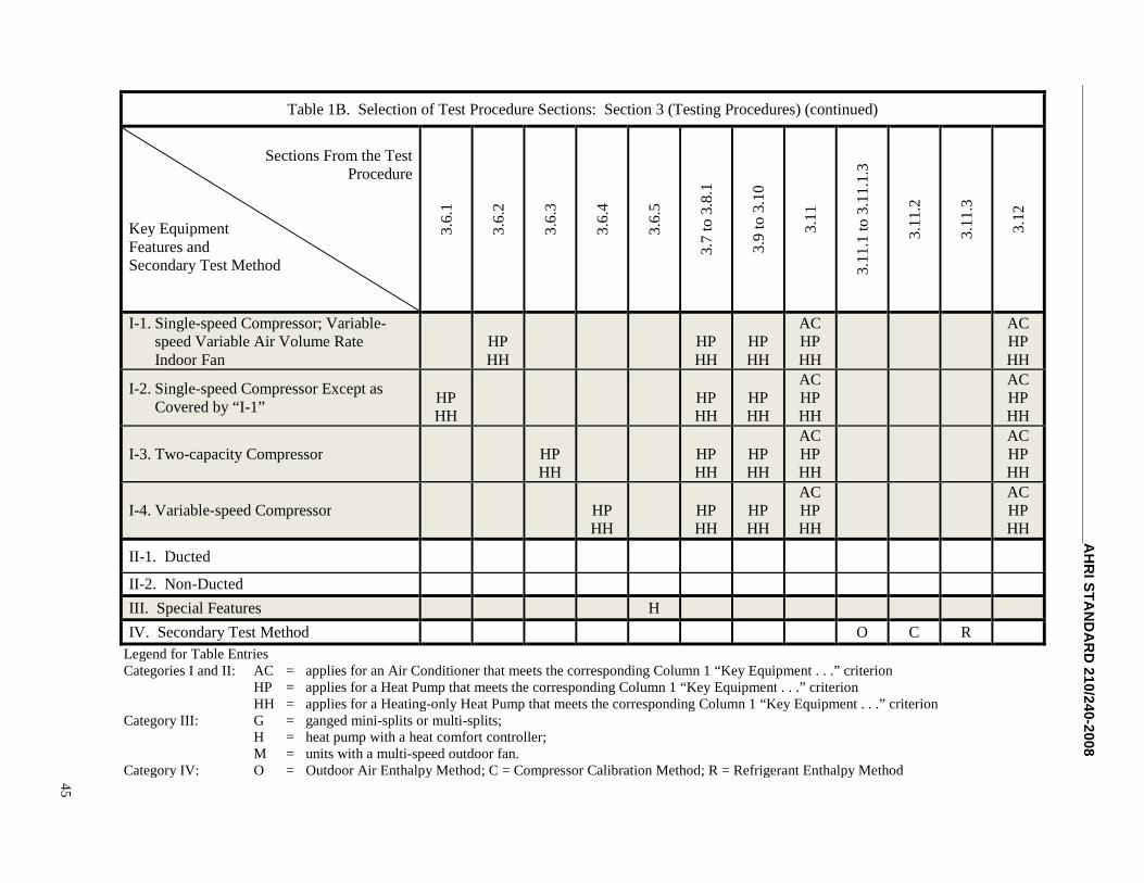
__
__
__
__
__
__
__
__
__
__
__
__
__
__
__
__
__
__
__
__
__
__
__
__
__
__
__
__
_A
HR
IS
TA
ND
AR
D2
10
/24
0-2
00
8
45
Table 1B. Selection of Test Procedure Sections: Section 3 (Testing Procedures) (continued)
Sections From the TestProcedure
Key EquipmentFeatures andSecondary Test Method
3.6
.1
3.6
.2
3.6
.3
3.6
.4
3.6
.5
3.7
to3.
8.1
3.9
to3.
10
3.1
1
3.1
1.1
to3
.11
.1.3
3.1
1.2
3.1
1.3
3.1
2
I-1. Single-speed Compressor; Variable-speed Variable Air Volume RateIndoor Fan
HPHH
HPHH
HPHH
ACHPHH
ACHPHH
I-2. Single-speed Compressor Except asCovered by “I-1”
HPHH
HPHH
HPHH
ACHPHH
ACHPHH
I-3. Two-capacity Compressor HPHH
HPHH
HPHH
ACHPHH
ACHPHH
I-4. Variable-speed Compressor HPHH
HPHH
HPHH
ACHPHH
ACHPHH
II-1. Ducted
II-2. Non-Ducted
III. Special Features H
IV. Secondary Test Method O C R
Legend for Table EntriesCategories I and II: AC = applies for an Air Conditioner that meets the corresponding Column 1 “Key Equipment . . .” criterion
HP = applies for a Heat Pump that meets the corresponding Column 1 “Key Equipment . . .” criterionHH = applies for a Heating-only Heat Pump that meets the corresponding Column 1 “Key Equipment . . .” criterion
Category III: G = ganged mini-splits or multi-splits;H = heat pump with a heat comfort controller;M = units with a multi-speed outdoor fan.
Category IV: O = Outdoor Air Enthalpy Method; C = Compressor Calibration Method; R = Refrigerant Enthalpy Method
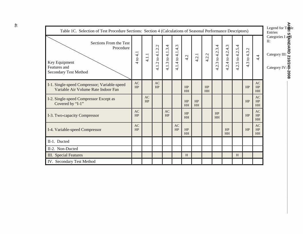
AH46
RI
ST
AN
DA
RD
21
0/2
40
-20
08
__
__
__
__
__
__
__
__
__
__
__
__
__
__
__
__
__
__
__
__
__
__
__
__
__
__
__
__
__
__
__
_
Legend for TableEntriesCategories I andII:
Category III:
Category IV:
Table 1C. Selection of Test Procedure Sections: Section 4 (Calculations of Seasonal Performance Descriptors)
Sections From the TestProcedure
Key EquipmentFeatures andSecondary Test Method
4to
4.1
4.1
.1
4.1
.2to
4.1
.2.2
4.1
.3to
4.1
.3.4
4.1
.4to
4.1
.4.3
4.2
4.2
.1
4.2
.2
4.2
.3to
4.2
.3.4
4.2
.4to
4.2
.4.3
4.2
.5to
4.2
.5.4
4.3
to4.
3.2
4.4
I-1. Single-speed Compressor; Variable-speedVariable Air Volume Rate Indoor Fan
ACHP
ACHP HP
HHHPHH
HPACHPHH
I-2. Single-speed Compressor Except asCovered by “I-1”
ACHP HP
HHHPHH
HPACHPHH
I-3. Two-capacity CompressorACHP
ACHP
HPHH
HPHH
HPACHPHH
I-4. Variable-speed CompressorACHP
ACHP HP
HHHPHH
HPACHPHH
II-1. Ducted
II-2. Non-Ducted
III. Special Features H H
IV. Secondary Test Method
AHRI STANDARD 210/240-2008
47
2.1 Test room requirements. a. Test using two side-by-side rooms, an indoor test room and an outdoor test room. Formultiple-split air conditioners and heat pumps (see Definition 1.30), however, use as many available indoor test rooms asneeded to accommodate the total number of indoor units. These rooms must comply with the requirements specified insections 8.1.2 and 8.1.3 of ASHRAE Standard 37-2005 (incorporated by reference, see §430.22).
b. Inside these test rooms, use artificial loads during cyclic tests and frost accumulation tests, if needed, to produce stabilizedroom air temperatures. For one room, select an electric resistance heater(s) having a heating capacity that is approximatelyequal to the heating capacity of the test unit's condenser. For the second room, select a heater(s) having a capacity that isclose to the sensible cooling capacity of the test unit's evaporator. When applied, cycle the heater located in the same room asthe test unit evaporator coil ON and OFF when the test unit cycles ON and OFF. Cycle the heater located in the same room asthe test unit condensing coil ON and OFF when the test unit cycles OFF and ON.
2.2 Test unit installation requirements. a. Install the unit according to section 8.2 of ASHRAE Standard 37-2005(incorporated by reference, see §430.22). With respect to interconnecting tubing used when testing split-systems, however,follow the requirements given in section 6.1.3.5 of AHRI Standard 210/240-2006 (incorporated by reference, see §430.22).When testing triple-split systems (see Definition 1.44), use the tubing length specified in section 6.1.3.5 of AHRI Standard210/240-2006 (incorporated by reference, see §430.22) to connect the outdoor coil, indoor compressor section, and indoorcoil while still meeting the requirement of exposing 10 feet of the tubing to outside conditions. When testing split systemshaving multiple indoor coils, connect each indoor fan-coil to the outdoor unit using: (a) 25 feet of tubing, or (b) tubingfurnished by the manufacturer, whichever is longer. If they are needed to make a secondary measurement of capacity, installrefrigerant pressure measuring instruments as described in section 8.2.5 of ASHRAE Standard 37-2005 (incorporated byreference, see §430.22). Refer to section 2.10 of this Appendix to learn which secondary methods require refrigerantpressure measurements. At a minimum, insulate the low-pressure line(s) of a split-system with insulation having an insidediameter that matches the refrigerant tubing and a nominal thickness of 0.5 inch.
b. For units designed for both horizontal and vertical installation or for both up-flow and down-flow vertical installations, themanufacturer must specify the orientation used for testing. Conduct testing with the following installed:
(1) the most restrictive filter(s);
(2) supplementary heating coils; and
(3) other equipment specified as part of the unit, including all hardware used by a heat comfort controller if soequipped (see Definition 1.28). For small-duct, high-velocity systems, configure all balance dampers or restrictordevices on or inside the unit to fully open or lowest restriction.
c. Testing a ducted unit without having an indoor air filter installed is permissible as long as the minimum external staticpressure requirement is adjusted as stated in Table 2, note 3 (see section 3.1.4). Except as noted in section 3.1.9, prevent theindoor air supplementary heating coils from operating during all tests. For coil-only indoor units that are supplied without anenclosure, create an enclosure using 1 inch fiberglass ductboard having a nominal density of 6 pounds per cubic foot. Oralternatively, use some other insulating material having a thermal resistance (“R” value) between 4 and 6 hr·ft 2 · °F/Btu. Forunits where the coil is housed within an enclosure or cabinet, no extra insulating or sealing is allowed.
2.2.1 Defrost control settings. Set heat pump defrost controls at the normal settings which most typify those encountered ingeneralized climatic region IV. (Refer to Figure 2 and Table 17 of section 4.2 for information on region IV.) For heat pumpsthat use a time-adaptive defrost control system (see Definition 1.42), the manufacturer must specify the frosting interval to beused during Frost Accumulation tests and provide the procedure for manually initiating the defrost at the specified time. Toease testing of any unit, the manufacturer should provide information and any necessary hardware to manually initiate adefrost cycle.
2.2.2 Special requirements for units having a multiple-speed outdoor fan. Configure the multiple-speed outdoor fanaccording to the manufacturer's specifications, and thereafter, leave it unchanged for all tests. The controls of the unit mustregulate the operation of the outdoor fan during all lab tests except dry coil cooling mode tests. For dry coil cooling modetests, the outdoor fan must operate at the same speed used during the required wet coil test conducted at the same outdoor testconditions.
2.2.3 Special requirements for multi-split air conditioners and heat pumps, and systems composed of multiple mini-splitunits (outdoor units located side-by-side) that would normally operate using two or more indoor thermostats. For any test
AHRI STANDARD 210/240-2008
48
where the system is operated at part load (i.e., one or more compressors “off”, operating at the intermediate or minimumcompressor speed, or at low compressor capacity), the manufacturer shall designate the particular indoor coils that are turnedoff during the test. For variable-speed systems, the manufacturer must designate at least one indoor unit that is turned off forall tests conducted at minimum compressor speed. For all other part-load tests, the manufacturer shall choose to turn offzero, one, two, or more indoor units. The chosen configuration shall remain unchanged for all tests conducted at the samecompressor speed/capacity. For any indoor coil that is turned off during a test, take steps to cease forced airflow through thisindoor coil and block its outlet duct. Because these types of systems will have more than one indoor fan and possiblymultiple outdoor fans and compressor systems, references in this test procedure to a single indoor fan, outdoor fan, andcompressor means all indoor fans, all outdoor fans, and all compressor systems that are turned on during the test.
2.2.4 Wet-bulb temperature requirements for the air entering the indoor and outdoor coils.
2.2.4.1 Cooling mode tests. For wet-coil cooling mode tests, regulate the water vapor content of the air entering the indoorunit to the applicable wet-bulb temperature listed in Tables 3 to 6. As noted in these same tables, achieve a wet-bulbtemperature during dry-coil cooling mode tests that results in no condensate forming on the indoor coil. Controlling the watervapor content of the air entering the outdoor side of the unit is not required for cooling mode tests except when testing:
(1) Units that reject condensate to the outdoor coil during wet coil tests. Tables 3–6 list the applicable wet-bulb temperatures.
(2) Single-packaged units where all or part of the indoor section is located in the outdoor test room. The average dew pointtemperature of the air entering the outdoor coil during wet coil tests must be within ±3.0 °F of the average dew pointtemperature of the air entering the indoor coil over the 30-minute data collection interval described in section 3.3. For drycoil tests on such units, it may be necessary to limit the moisture content of the air entering the outdoor side of the unit tomeet the requirements of section 3.4.
2.2.4.2 Heating mode tests. For heating mode tests, regulate the water vapor content of the air entering the outdoor unit to theapplicable wet-bulb temperature listed in Tables 9 to 12. The wet-bulb temperature entering the indoor side of the heat pumpmust not exceed 60 °F. Additionally, if the Outdoor Air Enthalpy test method is used while testing a single-packaged heatpump where all or part of the outdoor section is located in the indoor test room, adjust the wet-bulb temperature for the airentering the indoor side to yield an indoor-side dew point temperature that is as close as reasonably possible to the dew pointtemperature of the outdoor-side entering air.
2.2.5 Additional refrigerant charging requirements. Charging according to the “manufacturer’s published instructions,” asstated in section 8.2 of ASHRAE Standard 37-2005 (incorporated by reference, see §430.22), means the manufacturer’sinstallation instructions that come packaged with the unit.
2.3 Indoor air volume rates. If a unit's controls allow for overspeeding the indoor fan (usually on a temporary basis), takethe necessary steps to prevent overspeeding during all tests.
2.3.1 Cooling tests. a. Set indoor fan control options (e.g., fan motor pin settings, fan motor speed) according to thepublished installation instructions that are provided with the equipment while meeting the airflow requirements that arespecified in sections 3.1.4.1 to 3.1.4.3.
b. Express the Cooling Full-load Air Volume Rate, the Cooling Minimum Air Volume Rate, and the Cooling IntermediateAir Volume Rate in terms of standard air.
2.3.2 Heating tests. a. If needed, set the indoor fan control options (e.g., fan motor pin settings, fan motor speed) accordingto the published installation instructions that are provided with the equipment. Do this set-up while meeting all applicableairflow requirements specified in sections 3.1.4.4 to 3.1.4.7.
b. Express the Heating Full-load Air Volume Rate, the Heating Minimum Air Volume Rate, the Heating Intermediate AirVolume Rate, and the Heating Nominal Air Volume Rate in terms of standard air.
2.4 Indoor coil inlet and outlet duct connections. Insulate and/or construct the outlet plenum described in section 2.4.1and, if installed, the inlet plenum described in section 2.4.2 with thermal insulation having a nominal overall resistance(R-value) of at least 19 hr·ft 2 °F/Btu.2.4.1 Outlet plenum for the indoor unit. a. Attach a plenum to the outlet of the indoorcoil. (Note: for some packaged systems, the indoor coil may be located in the outdoor test room.)
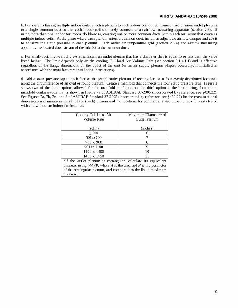
AHRI STANDARD 210/240-2008
49
b. For systems having multiple indoor coils, attach a plenum to each indoor coil outlet. Connect two or more outlet plenumsto a single common duct so that each indoor coil ultimately connects to an airflow measuring apparatus (section 2.6). Ifusing more than one indoor test room, do likewise, creating one or more common ducts within each test room that containsmultiple indoor coils. At the plane where each plenum enters a common duct, install an adjustable airflow damper and use itto equalize the static pressure in each plenum. Each outlet air temperature grid (section 2.5.4) and airflow measuringapparatus are located downstream of the inlet(s) to the common duct.
c. For small-duct, high-velocity systems, install an outlet plenum that has a diameter that is equal to or less than the valuelisted below. The limit depends only on the cooling Full-load Air Volume Rate (see section 3.1.4.1.1) and is effectiveregardless of the flange dimensions on the outlet of the unit (or an air supply plenum adapter accessory, if installed inaccordance with the manufacturers installation instructions).
d. Add a static pressure tap to each face of the (each) outlet plenum, if rectangular, or at four evenly distributed locationsalong the circumference of an oval or round plenum. Create a manifold that connects the four static pressure taps. Figure 1shows two of the three options allowed for the manifold configuration; the third option is the broken-ring, four-to-onemanifold configuration that is shown in Figure 7a of ASHRAE Standard 37-2005 (incorporated by reference, see §430.22).See Figures 7a, 7b, 7c, and 8 of ASHRAE Standard 37-2005 (incorporated by reference, see §430.22) for the cross-sectionaldimensions and minimum length of the (each) plenum and the locations for adding the static pressure taps for units testedwith and without an indoor fan installed.
Cooling Full-Load AirVolume Rate
(scfm)
Maximum Diameter* ofOutlet Plenum
(inches)≤ 500 6
501to 700 7701 to 900 8
901 to 1100 91101 to 1400 101401 to 1750 11
*If the outlet plenum is rectangular, calculate its equivalentdiameter using (4A)/P, where A is the area and P is the perimeterof the rectangular plenum, and compare it to the listed maximumdiameter.
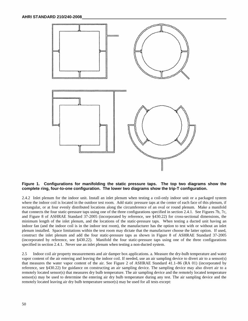
AHRI STANDARD 210/240-2008
50
Figure 1. Configurations for manifolding the static pressure taps. The top two diagrams show thecomplete ring, four-to-one configuration. The lower two diagrams show the trip-T configuration.
2.4.2 Inlet plenum for the indoor unit. Install an inlet plenum when testing a coil-only indoor unit or a packaged systemwhere the indoor coil is located in the outdoor test room. Add static pressure taps at the center of each face of this plenum, ifrectangular, or at four evenly distributed locations along the circumference of an oval or round plenum. Make a manifoldthat connects the four static-pressure taps using one of the three configurations specified in section 2.4.1. See Figures 7b, 7c,and Figure 8 of ASHRAE Standard 37-2005 (incorporated by reference, see §430.22) for cross-sectional dimensions, theminimum length of the inlet plenum, and the locations of the static-pressure taps. When testing a ducted unit having anindoor fan (and the indoor coil is in the indoor test room), the manufacturer has the option to test with or without an inletplenum installed. Space limitations within the test room may dictate that the manufacturer choose the latter option. If used,construct the inlet plenum and add the four static-pressure taps as shown in Figure 8 of ASHRAE Standard 37-2005(incorporated by reference, see §430.22). Manifold the four static-pressure taps using one of the three configurationsspecified in section 2.4.1. Never use an inlet plenum when testing a non-ducted system.
2.5 Indoor coil air property measurements and air damper box applications. a. Measure the dry-bulb temperature and watervapor content of the air entering and leaving the indoor coil. If needed, use an air sampling device to divert air to a sensor(s)that measures the water vapor content of the air. See Figure 2 of ASHRAE Standard 41.1–86 (RA 01) (incorporated byreference, see §430.22) for guidance on constructing an air sampling device. The sampling device may also divert air to aremotely located sensor(s) that measures dry bulb temperature. The air sampling device and the remotely located temperaturesensor(s) may be used to determine the entering air dry bulb temperature during any test. The air sampling device and theremotely located leaving air dry bulb temperature sensor(s) may be used for all tests except:
AHRI STANDARD 210/240-2008
51
(1) Cyclic tests; and
(2) Frost accumulation tests.
b. An acceptable alternative in all cases, including the two special cases noted above, is to install a grid of dry bulbtemperature sensors within the outlet and inlet ducts. Use a temperature grid to get the average dry bulb temperature at onelocation, leaving or entering, or when two grids are applied as a thermopile, to directly obtain the temperature difference. Agrid of temperature sensors (which may also be used for determining average leaving air dry bulb temperature) is required tomeasure the temperature distribution within a cross-section of the leaving airstream.
c. Use an inlet and outlet air damper box when testing ducted systems if conducting one or both of the cyclic tests listed insections 3.2 and 3.6. Otherwise, install an outlet air damper box when testing heat pumps, both ducted and non-ducted, thatcycle off the indoor fan during defrost cycles if no other means is available for preventing natural or forced convectionthrough the indoor unit when the indoor fan is off. Never use an inlet damper box when testing a non-ducted system.
2.5.1 Test set-up on the inlet side of the indoor coil: for cases where the inlet damper box is installed. a. Install the inlet sidedamper box as specified in section 2.5.1.1 or 2.5.1.2, whichever applies. Insulate or construct the ductwork between the pointwhere the air damper is installed and where the connection is made to either the inlet plenum (section 2.5.1.1 units) or theindoor unit (section 2.5.1.2 units) with thermal insulation that has a nominal overall resistance (R-value) of at least 19 hr·ft 2 ·°F/Btu.
b. Locate the grid of entering air dry-bulb temperature sensors, if used, at the inlet of the damper box. Locate the air samplingdevice, or the sensor used to measure the water vapor content of the inlet air, at a location immediately upstream of thedamper box inlet.
2.5.1.1 If the section 2.4.2 inlet plenum is installed. Install the inlet damper box upstream of the inlet plenum. The cross-sectional flow area of the damper box must be equal to or greater than the flow area of the inlet plenum. If needed, use anadaptor plate or a transition duct section to connect the damper box with the inlet plenum.
2.5.1.2 If the section 2.4.2 inlet plenum is not installed. Install the damper box immediately upstream of the air inlet of theindoor unit. The cross-sectional dimensions of the damper box must be equal to or greater than the dimensions of the indoorunit inlet. If needed, use an adaptor plate or a short transition duct section to connect the damper box with the unit's air inlet.Add static pressure taps at the center of each face of the damper box, if rectangular, or at four evenly distributed locationsalong the circumference, if oval or round. Locate the pressure taps between the inlet damper and the inlet of the indoor unit.Make a manifold that connects the four static pressure taps.
2.5.2 Test set-up on the inlet side of the indoor unit: for cases where no inlet damper box is installed. If using the section2.4.2 inlet plenum and a grid of dry bulb temperature sensors, mount the grid at a location upstream of the static pressure tapsdescribed in section 2.4.2, preferably at the entrance plane of the inlet plenum. If the section 2.4.2 inlet plenum is not used,but a grid of dry bulb temperature sensors is used, locate the grid approximately 6 inches upstream from the inlet of theindoor coil. Or, in the case of non-ducted units having multiple indoor coils, locate a grid approximately 6 inches upstreamfrom the inlet of each indoor coil. Position an air sampling device, or the sensor used to measure the water vapor content ofthe inlet air, immediately upstream of the (each) entering air dry-bulb temperature sensor grid. If a grid of sensors is not used,position the entering air sampling device (or the sensor used to measure the water vapor content of the inlet air) as if the gridwere present.
2.5.3 Indoor coil static pressure difference measurement. Section 6.5.2 of ASHRAE Standard 37-2005 (incorporated byreference, see §430.22) describes the method for fabricating static pressure taps. Also refer to Figure 2A of ASHRAEStandard 51–99/AMCA Standard 210–99 (incorporated by reference, see §430.22). Use a differential pressure measuringinstrument that is accurate to within ±0.01 inches of water and has a resolution of at least 0.01 inches of water to measure thestatic pressure difference between the indoor coil air inlet and outlet. Connect one side of the differential pressure instrumentto the manifolded pressure taps installed in the outlet plenum. Connect the other side of the instrument to the manifoldedpressure taps located in either the inlet plenum or incorporated within the air damper box. If an inlet plenum or inlet damperbox are not used, leave the inlet side of the differential pressure instrument open to the surrounding atmosphere. For non-ducted systems that are tested with multiple outlet plenums, measure the static pressure within each outlet plenum relative tothe surrounding atmosphere.
AHRI STANDARD 210/240-2008
52
2.5.4 Test set-up on the outlet side of the indoor coil. a. Install an interconnecting duct between the outlet plenum describedin section 2.4.1 and the airflow measuring apparatus described below in section 2.6. The cross-sectional flow area of theinterconnecting duct must be equal to or greater than the flow area of the outlet plenum or the common duct used whentesting non-ducted units having multiple indoor coils. If needed, use adaptor plates or transition duct sections to allow theconnections. To minimize leakage, tape joints within the interconnecting duct (and the outlet plenum). Construct or insulatethe entire flow section with thermal insulation having a nominal overall resistance (R-value) of at least 19 hr·ft 2 · °F/Btu.
b. Install a grid(s) of dry-bulb temperature sensors inside the interconnecting duct. Also, install an air sampling device, or thesensor(s) used to measure the water vapor content of the outlet air, inside the interconnecting duct. Locate the dry-bulbtemperature grid(s) upstream of the air sampling device (or the in-duct sensor(s) used to measure the water vapor content ofthe outlet air). Air that circulates through an air sampling device and past a remote water-vapor-content sensor(s) must bereturned to the interconnecting duct at a point:
(1) Downstream of the air sampling device;
(2) Upstream of the outlet air damper box, if installed; and
(3) Upstream of the section 2.6 airflow measuring apparatus.
2.5.4.1 Outlet air damper box placement and requirements. If using an outlet air damper box (see section 2.5), install it withinthe interconnecting duct at a location downstream of the location where air from the sampling device is reintroduced ordownstream of the in-duct sensor that measures water vapor content of the outlet air. The leakage rate from the combinationof the outlet plenum, the closed damper, and the duct section that connects these two components must not exceed 20 cubicfeet per minute when a negative pressure of 1 inch of water column is maintained at the plenum's inlet.
2.5.4.2 Procedures to minimize temperature maldistribution. Use these procedures if necessary to correct temperaturemaldistributions. Install a mixing device(s) upstream of the outlet air, dry-bulb temperature grid (but downstream of theoutlet plenum static pressure taps). Use a perforated screen located between the mixing device and the dry-bulb temperaturegrid, with a maximum open area of 40 percent. One or both items should help to meet the maximum outlet air temperaturedistribution specified in section 3.1.8. Mixing devices are described in sections 6.3—6.5 of ASHRAE Standard 41.1–86 (RA01) (incorporated by reference, see §430.22) and section 5.2.2 of ASHRAE Standard 41.2–87 (RA 92) (incorporated byreference, see §430.22).
2.5.4.3 Minimizing air leakage. For small-duct, high-velocity systems, install an air damper near the end of theinterconnecting duct, just prior to the transition to the airflow measuring apparatus of section 2.6. To minimize air leakage,adjust this damper such that the pressure in the receiving chamber of the airflow measuring apparatus is no more than 0.5inch of water higher than the surrounding test room ambient. In lieu of installing a separate damper, use the outlet air damperbox of sections 2.5 and 2.5.4.1 if it allows variable positioning. Also apply these steps to any conventional indoor blowerunit that creates a static pressure within the receiving chamber of the airflow measuring apparatus that exceeds the test roomambient pressure by more than 0.5 inches of water column.
2.5.5 Dry bulb temperature measurement. a. Measure dry bulb temperatures as specified in sections 4, 5, 6.1–6.10, 9, 10,and 11 of ASHRAE Standard 41.1–86 (RA 01) (incorporated by reference, see §430.22). The transient testing requirementscited in section 4.3 of ASHRAE Standard 41.1–86 (RA 01) (incorporated by reference, see §430.22) apply if conducting acyclic or frost accumulation test.
b. Distribute the sensors of a dry-bulb temperature grid over the entire flow area. The required minimum is 9 sensors per grid.
2.5.6 Water vapor content measurement. Determine water vapor content by measuring dry-bulb temperature combined withthe air wet-bulb temperature, dew point temperature, or relative humidity. If used, construct and apply wet-bulb temperaturesensors as specified in sections 4, 5, 6, 9, 10, and 11 of ASHRAE Standard 41.1–86 (RA 01) (incorporated by reference, see§430.22). As specified in ASHRAE 41.1–86 (RA 01) (incorporated by reference, see §430.22), the temperature sensor (wickremoved) must be accurate to within ±0.2 °F. If used, apply dew point hygrometers as specified in sections 5 and 8 ofASHRAE Standard 41.6–94 (RA 01) (incorporated by reference, see §430.22). The dew point hygrometers must be accurateto within ±0.4 °F when operated at conditions that result in the evaluation of dew points above 35 °F. If used, a relativehumidity (RH) meter must be accurate to within ±0.7% RH. Other means to determine the psychrometric state of air may beused as long as the measurement accuracy is equivalent to or better than the accuracy achieved from using a wet-bulbtemperature sensor that meets the above specifications.
AHRI STANDARD 210/240-2008
53
2.5.7 Air damper box performance requirements. If used (see section 2.5), the air damper box(es) must be capable of beingcompletely opened or completely closed within 10 seconds for each action.
2.6 Airflow measuring apparatus. a. Fabricate and operate an Air Flow Measuring Apparatus as specified in section 6.6 ofASHRAE Standard 116–95 (RA05) (incorporated by reference, see §430.22). Refer to Figure 12 of ASHRAE Standard 51–99/AMCA Standard 210–99 (incorporated by reference, see §430.22) or Figure 14 of ASHRAE Standard 41.2–87 (RA 92)(incorporated by reference, see §430.22) for guidance on placing the static pressure taps and positioning the diffusion baffle(settling means) relative to the chamber inlet.
b. Connect the airflow measuring apparatus to the interconnecting duct section described in section 2.5.4. See sections 6.1.1,6.1.2, and 6.1.4, and Figures 1, 2, and 4 of ASHRAE Standard 37–2005 (incorporated by reference, see §430.22), and FiguresD1, D2, and D4 of AHRI Standard 210/240–2006 (incorporated by reference, see §430.22) for illustrative examples of howthe test apparatus may be applied within a complete laboratory set-up. Instead of following one of these examples, analternative set-up may be used to handle the air leaving the airflow measuring apparatus and to supply properly conditionedair to the test unit's inlet. The alternative set-up, however, must not interfere with the prescribed means for measuring airflowrate, inlet and outlet air temperatures, inlet and outlet water vapor contents, and external static pressures, nor create abnormalconditions surrounding the test unit. (Note: Do not use an enclosure as described in section 6.1.3 of ASHRAE Standard 37–2005 (incorporated by reference, see §430.22) when testing triple-split units.)
2.7 Electrical voltage supply. Perform all tests at the voltage specified in section 6.1.3.2 of AHRI Standard 210/240–2006(incorporated by reference, see §430.22) for “Standard Rating Tests.” Measure the supply voltage at the terminals on the testunit using a volt meter that provides a reading that is accurate to within ±1.0 percent of the measured quantity.
2.8 Electrical power and energy measurements. a. Use an integrating power (watt-hour) measuring system to determinethe electrical energy or average electrical power supplied to all components of the air conditioner or heat pump (includingauxiliary components such as controls, transformers, crankcase heater, integral condensate pump on non-ducted indoor units,etc.). The watt-hour measuring system must give readings that are accurate to within ±0.5 percent. For cyclic tests, thisaccuracy is required during both the ON and OFF cycles. Use either two different scales on the same watt-hour meter or twoseparate watt-hour meters. Activate the scale or meter having the lower power rating within 15 seconds after beginning anOFF cycle. Activate the scale or meter having the higher power rating active within 15 seconds prior to beginning an ONcycle. For ducted units tested with a fan installed, the ON cycle lasts from compressor ON to indoor fan OFF. For ductedunits tested without an indoor fan installed, the ON cycle lasts from compressor ON to compressor OFF. For non-ductedunits, the ON cycle lasts from indoor fan ON to indoor fan OFF. When testing air conditioners and heat pumps having avariable-speed compressor, avoid using an induction watt/watt-hour meter.
b. When performing section 3.5 and/or 3.8 cyclic tests on non-ducted units, provide instrumentation to determine the averageelectrical power consumption of the indoor fan motor to within ±1.0 percent. If required according to sections 3.3, 3.4, 3.7,3.9.1, and/or 3.10, this same instrumentation requirement applies when testing air conditioners and heat pumps having avariable-speed constant-air-volume-rate indoor fan or a variable-speed, variable-air-volume-rate indoor fan.
2.9 Time measurements. Make elapsed time measurements using an instrument that yields readings accurate to within±0.2 percent.
2.10 Test apparatus for the secondary space conditioning capacity measurement. For all tests, use the Indoor Air EnthalpyMethod to measure the unit's capacity. This method uses the test set-up specified in sections 2.4 to 2.6. In addition, for allsteady-state tests, conduct a second, independent measurement of capacity as described in section 3.1.1. For split systems,use one of the following secondary measurement methods: Outdoor Air Enthalpy Method, Compressor Calibration Method,or Refrigerant Enthalpy Method. For single packaged units, use either the Outdoor Air Enthalpy Method or the CompressorCalibration Method as the secondary measurement.
AHRI STANDARD 210/240-2008
54
2.10.1 Outdoor Air Enthalpy Method. a. To make a secondary measurement of indoor space conditioning capacity usingthe Outdoor Air Enthalpy Method, do the following:
(1) Measure the electrical power consumption of the test unit;
(2) Measure the air-side capacity at the outdoor coil; and
(3) Apply a heat balance on the refrigerant cycle.
b. The test apparatus required for the Outdoor Air Enthalpy Method is a subset of the apparatus used for the Indoor AirEnthalpy Method. Required apparatus includes the following:
(1) An outlet plenum containing static pressure taps (sections 2.4, 2.4.1, and 2.5.3),
(2) An airflow measuring apparatus (section 2.6),
(3) A duct section that connects these two components and itself contains the instrumentation for measuring the dry-bulbtemperature and water vapor content of the air leaving the outdoor coil (sections 2.5.4, 2.5.5, and 2.5.6), and
(4) On the inlet side, a sampling device and optional temperature grid (sections 2.5 and 2.5.2).
c. During the preliminary tests described in sections 3.11.1 and 3.11.1.1, measure the evaporator and condenser temperaturesor pressures. On both the outdoor coil and the indoor coil, solder a thermocouple onto a return bend located at or near themidpoint of each coil or at points not affected by vapor superheat or liquid subcooling. Alternatively, if the test unit is notsensitive to the refrigerant charge, connect pressure gages to the access valves or to ports created from tapping into thesuction and discharge lines. Use this alternative approach when testing a unit charged with a zeotropic refrigerant having atemperature glide in excess of 1 °F at the specified test conditions.
2.10.2 Compressor Calibration Method. Measure refrigerant pressures and temperatures to determine the evaporatorsuperheat and the enthalpy of the refrigerant that enters and exits the indoor coil. Determine refrigerant flow rate or, when thesuperheat of the refrigerant leaving the evaporator is less than 5 °F, total capacity from separate calibration tests conductedunder identical operating conditions. When using this method, install instrumentation, measure refrigerant properties, andadjust the refrigerant charge according to section 7.4.2 of ASHRAE Standard 37–2005 (incorporated by reference, see§430.22). Use refrigerant temperature and pressure measuring instruments that meet the specifications given in sections 5.1.1and 5.2 of ASHRAE Standard 37–2005 (incorporated by reference, see §430.22).
2.10.3 Refrigerant Enthalpy Method. For this method, calculate space conditioning capacity by determining the refrigerantenthalpy change for the indoor coil and directly measuring the refrigerant flow rate. Use section 7.5.2 of ASHRAE Standard37–2005 (incorporated by reference, see §430.22) for the requirements for this method, including the additionalinstrumentation requirements, and information on placing the flow meter and a sight glass. Use refrigerant temperature,pressure, and flow measuring instruments that meet the specifications given in sections 5.1.1, 5.2, and 5.5.1 of ASHRAEStandard 37–2005 (incorporated by reference, see §430.22).
2.11 Measurement of test room ambient conditions. a. If using a test set-up where air is ducted directly from theconditioning apparatus to the indoor coil inlet (see Figure 2, Loop Air-Enthalpy Test Method Arrangement, of ASHRAEStandard 37–2005 (incorporated by reference, see §430.22)), add instrumentation to permit measurement of the indoor testroom dry-bulb temperature.
b. If the Outdoor Air Enthalpy Method is not used, add instrumentation to measure the dry-bulb temperature and the watervapor content of the air entering the outdoor coil. If an air sampling device is used, construct and apply the device as persection 6 of ASHRAE Standard 41.1–86 (RA 01) (incorporated by reference, see §430.22). Take steps (e.g., add or re-position a lab circulating fan), as needed, to minimize the magnitude of the temperature distribution non-uniformity. Positionany fan in the outdoor test room while trying to keep air velocities in the vicinity of the test unit below 500 feet per minute.
c. Measure dry bulb temperatures as specified in sections 4, 5, 6.1–6.10, 9, 10, and 11 of ASHRAE Standard 41.1–86(RA 01) (incorporated by reference, see §430.22). Measure water vapor content as stated above in section 2.5.6.
AHRI STANDARD 210/240-2008
55
2.12 Measurement of indoor fan speed. When required, measure fan speed using a revolution counter, tachometer, orstroboscope that gives readings accurate to within ±1.0 percent.
2.13 Measurement of barometric pressure. Determine the average barometric pressure during each test. Use an instrumentthat meets the requirements specified in section 5.2 of ASHRAE Standard 37–2005 (incorporated by reference, see §430.22).
3. Testing Procedures
3.1 General Requirements. If, during the testing process, an equipment set-up adjustment is made that would alter theperformance of the unit when conducting an already completed test, then repeat all tests affected by the adjustment. Forcyclic tests, instead of maintaining an air volume rate, for each airflow nozzle, maintain the static pressure difference orvelocity pressure during an ON period at the same pressure difference or velocity pressure as measured during the steady-state test conducted at the same test conditions.
3.1.1 Primary and secondary test methods. For all tests, use the Indoor Air Enthalpy Method test apparatus to determine theunit's space conditioning capacity. The procedure and data collected, however, differ slightly depending upon whether thetest is a steady-state test, a cyclic test, or a frost accumulation test. The following sections described these differences. For allsteady-state tests (i.e., the A, A2, A1, B, B2, B1, C, C1, EV, F1, G1, H01, H1, H12, H11, HIN, H3, H32, and H31 Tests), inaddition, use one of the acceptable secondary methods specified in section 2.10 to determine indoor space conditioningcapacity. Calculate this secondary check of capacity according to section 3.11. The two capacity measurements must agree towithin 6 percent to constitute a valid test. For this capacity comparison, use the Indoor Air Enthalpy Method capacity that iscalculated in section 7.3 of ASHRAE Standard 37-2005 (incorporated by reference, see §430.22) (and, if testing a coil-onlyunit, do not make the after-test fan heat adjustments described in section 3.3, 3.4, 3.7, and 3.10 of this Appendix). However,include the appropriate section 3.3 to 3.5 and 3.7 to 3.10 fan heat adjustments within the Indoor Air Enthalpy Methodcapacities used for the section 4 seasonal calculations.
3.1.2 Manufacturer-provided equipment overrides. Where needed, the manufacturer must provide a means for overriding thecontrols of the test unit so that the compressor(s) operates at the specified speed or capacity and the indoor fan operates at thespecified speed or delivers the specified air volume rate.
3.1.3 Airflow through the outdoor coil. For all tests, meet the requirements given in section 6.1.3.4 of AHRI Standard210/240–2006 (incorporated by reference, see §430.22) when obtaining the airflow through the outdoor coil.
3.1.4 Airflow through the indoor coil.
3.1.4.1 Cooling Full-load Air Volume Rate.
3.1.4.1.1 Cooling Full-load Air Volume Rate for Ducted Units. The manufacturer must specify the Cooling Full-load AirVolume Rate. Use this value as long as the following two requirements are satisfied. First, when conducting the A or A2
Test (exclusively), the measured air volume rate, when divided by the measured indoor air-side total cooling capacity mustnot exceed 37.5 cubic feet per minute of standard air (scfm) per 1000 Btu/h. If this ratio is exceeded, reduce the air volumerate until this ratio is equaled. Use this reduced air volume rate for all tests that call for using the Cooling Full-load AirVolume Rate. The second requirement is as follows:
a. For all ducted units tested with an indoor fan installed, except those having a variable-speed, constant-air-volume-rate indoor fan. The second requirement applies exclusively to the A or A2 Test and is met as follows.
(1) Achieve the Cooling Full-load Air Volume Rate, determined in accordance with the previous paragraph;
(2) Measure the external static pressure;
(3) If this pressure is equal to or greater than the applicable minimum external static pressure cited in Table 2, thissecond requirement is satisfied. Use the current air volume rate for all tests that require the Cooling Full-load AirVolume Rate.
(4) If the Table 2 minimum is not equaled or exceeded,
(4a) reduce the air volume rate until the applicable Table 2 minimum is equaled or
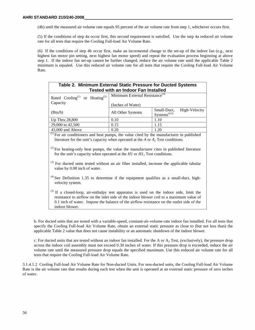
AHRI STANDARD 210/240-2008
56
(4b) until the measured air volume rate equals 95 percent of the air volume rate from step 1, whichever occurs first.
(5) If the conditions of step 4a occur first, this second requirement is satisfied. Use the step 4a reduced air volumerate for all tests that require the Cooling Full-load Air Volume Rate.
(6) If the conditions of step 4b occur first, make an incremental change to the set-up of the indoor fan (e.g., nexthighest fan motor pin setting, next highest fan motor speed) and repeat the evaluation process beginning at abovestep 1. If the indoor fan set-up cannot be further changed, reduce the air volume rate until the applicable Table 2minimum is equaled. Use this reduced air volume rate for all tests that require the Cooling Full-load Air VolumeRate.
Table 2. Minimum External Static Pressure for Ducted SystemsTested with an Indoor Fan Installed
Rated Cooling(1) or Heating(2)
Capacity
(Btu/h)
Minimum External Resistance(3)
(Inches of Water)
All Other SystemsSmall-Duct, High-VelocitySystems(4,5)
Up Thru 28,800 0.10 1.1029,000 to 42,500 0.15 1.1543,000 and Above 0.20 1.20(1) For air conditioners and heat pumps, the value cited by the manufacturer in published
literature for the unit’s capacity when operated at the A or A2 Test conditions.
(2) For heating-only heat pumps, the value the manufacturer cites in published literaturefor the unit’s capacity when operated at the H1 or H12 Test conditions.
(3) For ducted units tested without an air filter installed, increase the applicable tabularvalue by 0.08 inch of water.
(4) See Definition 1.35 to determine if the equipment qualifies as a small-duct, high-velocity system.
(5) If a closed-loop, air-enthalpy test apparatus is used on the indoor side, limit theresistance to airflow on the inlet side of the indoor blower coil to a maximum value of0.1 inch of water. Impose the balance of the airflow resistance on the outlet side of theindoor blower.
b. For ducted units that are tested with a variable-speed, constant-air-volume-rate indoor fan installed. For all tests thatspecify the Cooling Full-load Air Volume Rate, obtain an external static pressure as close to (but not less than) theapplicable Table 2 value that does not cause instability or an automatic shutdown of the indoor blower.
c. For ducted units that are tested without an indoor fan installed. For the A or A2 Test, (exclusively), the pressure dropacross the indoor coil assembly must not exceed 0.30 inches of water. If this pressure drop is exceeded, reduce the airvolume rate until the measured pressure drop equals the specified maximum. Use this reduced air volume rate for alltests that require the Cooling Full-load Air Volume Rate.
3.1.4.1.2 Cooling Full-load Air Volume Rate for Non-ducted Units. For non-ducted units, the Cooling Full-load Air VolumeRate is the air volume rate that results during each test when the unit is operated at an external static pressure of zero inchesof water.
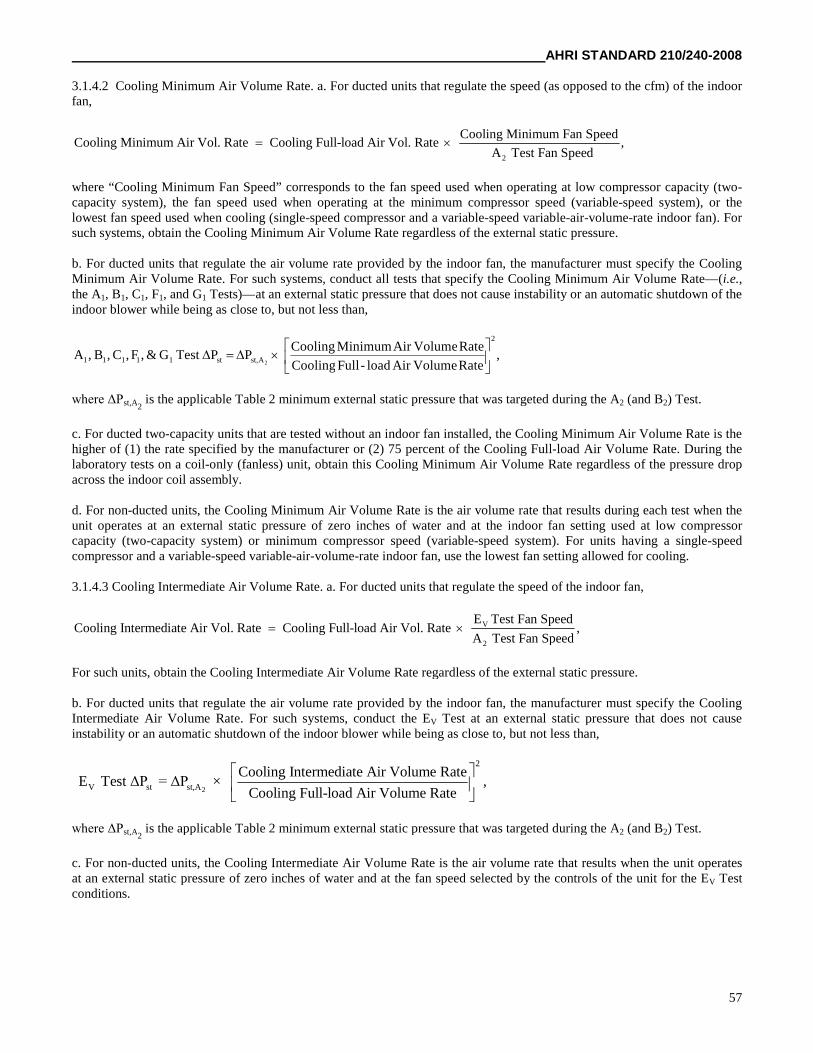
AHRI STANDARD 210/240-2008
57
3.1.4.2 Cooling Minimum Air Volume Rate. a. For ducted units that regulate the speed (as opposed to the cfm) of the indoorfan,
2
Cooling Minimum Fan SpeedCooling Minimum Air Vol. Rate Cooling Full-load Air Vol. Rate ,
A Test Fan Speed
where “Cooling Minimum Fan Speed” corresponds to the fan speed used when operating at low compressor capacity (two-capacity system), the fan speed used when operating at the minimum compressor speed (variable-speed system), or thelowest fan speed used when cooling (single-speed compressor and a variable-speed variable-air-volume-rate indoor fan). Forsuch systems, obtain the Cooling Minimum Air Volume Rate regardless of the external static pressure.
b. For ducted units that regulate the air volume rate provided by the indoor fan, the manufacturer must specify the CoolingMinimum Air Volume Rate. For such systems, conduct all tests that specify the Cooling Minimum Air Volume Rate—(i.e.,the A1, B1, C1, F1, and G1 Tests)—at an external static pressure that does not cause instability or an automatic shutdown of theindoor blower while being as close to, but not less than,
,RateVolumeAirload-FullCooling
RateVolumeAirMinimumCoolingPPTestG&,F,C,B,A
2
Ast,st11111 2
where ΔPst,A2is the applicable Table 2 minimum external static pressure that was targeted during the A2 (and B2) Test.
c. For ducted two-capacity units that are tested without an indoor fan installed, the Cooling Minimum Air Volume Rate is thehigher of (1) the rate specified by the manufacturer or (2) 75 percent of the Cooling Full-load Air Volume Rate. During thelaboratory tests on a coil-only (fanless) unit, obtain this Cooling Minimum Air Volume Rate regardless of the pressure dropacross the indoor coil assembly.
d. For non-ducted units, the Cooling Minimum Air Volume Rate is the air volume rate that results during each test when theunit operates at an external static pressure of zero inches of water and at the indoor fan setting used at low compressorcapacity (two-capacity system) or minimum compressor speed (variable-speed system). For units having a single-speedcompressor and a variable-speed variable-air-volume-rate indoor fan, use the lowest fan setting allowed for cooling.
3.1.4.3 Cooling Intermediate Air Volume Rate. a. For ducted units that regulate the speed of the indoor fan,
V
2
E Test Fan SpeedCooling Intermediate Air Vol. Rate Cooling Full-load Air Vol. Rate ,
A Test Fan Speed
For such units, obtain the Cooling Intermediate Air Volume Rate regardless of the external static pressure.
b. For ducted units that regulate the air volume rate provided by the indoor fan, the manufacturer must specify the CoolingIntermediate Air Volume Rate. For such systems, conduct the EV Test at an external static pressure that does not causeinstability or an automatic shutdown of the indoor blower while being as close to, but not less than,
2
2
V st st,A
Cooling Intermediate Air Volume RateE Test ΔP = ΔP × ,
Cooling Full-load Air Volume Rate
where ΔPst,A2is the applicable Table 2 minimum external static pressure that was targeted during the A2 (and B2) Test.
c. For non-ducted units, the Cooling Intermediate Air Volume Rate is the air volume rate that results when the unit operatesat an external static pressure of zero inches of water and at the fan speed selected by the controls of the unit for the EV Testconditions.
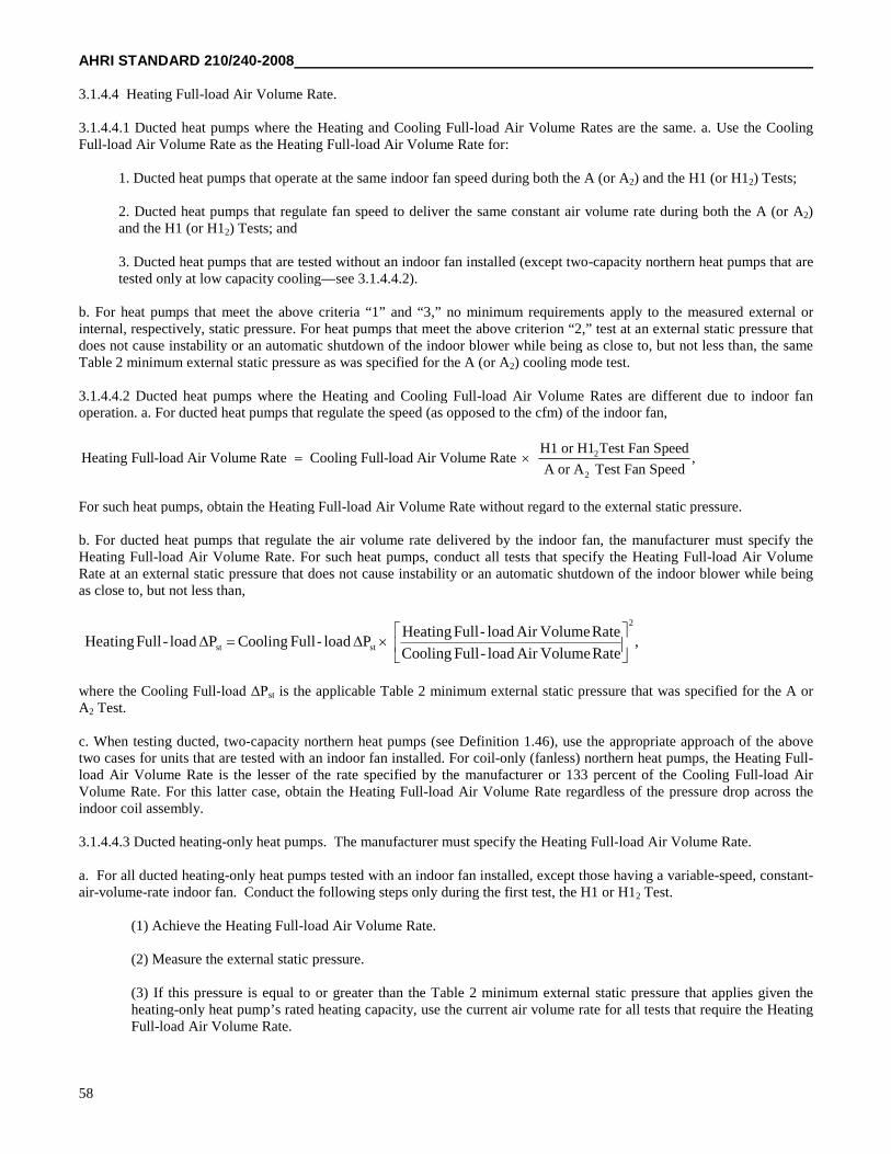
AHRI STANDARD 210/240-2008
58
3.1.4.4 Heating Full-load Air Volume Rate.
3.1.4.4.1 Ducted heat pumps where the Heating and Cooling Full-load Air Volume Rates are the same. a. Use the CoolingFull-load Air Volume Rate as the Heating Full-load Air Volume Rate for:
1. Ducted heat pumps that operate at the same indoor fan speed during both the A (or A2) and the H1 (or H12) Tests;
2. Ducted heat pumps that regulate fan speed to deliver the same constant air volume rate during both the A (or A2)and the H1 (or H12) Tests; and
3. Ducted heat pumps that are tested without an indoor fan installed (except two-capacity northern heat pumps that aretested only at low capacity cooling—see 3.1.4.4.2).
b. For heat pumps that meet the above criteria “1” and “3,” no minimum requirements apply to the measured external orinternal, respectively, static pressure. For heat pumps that meet the above criterion “2,” test at an external static pressure thatdoes not cause instability or an automatic shutdown of the indoor blower while being as close to, but not less than, the sameTable 2 minimum external static pressure as was specified for the A (or A2) cooling mode test.
3.1.4.4.2 Ducted heat pumps where the Heating and Cooling Full-load Air Volume Rates are different due to indoor fanoperation. a. For ducted heat pumps that regulate the speed (as opposed to the cfm) of the indoor fan,
2
2
H1 or H1 Test Fan SpeedHeating Full-load Air Volume Rate Cooling Full-load Air Volume Rate ,
A or A Test Fan Speed
For such heat pumps, obtain the Heating Full-load Air Volume Rate without regard to the external static pressure.
b. For ducted heat pumps that regulate the air volume rate delivered by the indoor fan, the manufacturer must specify theHeating Full-load Air Volume Rate. For such heat pumps, conduct all tests that specify the Heating Full-load Air VolumeRate at an external static pressure that does not cause instability or an automatic shutdown of the indoor blower while beingas close to, but not less than,
,RateVolumeAirload-FullCooling
RateVolumeAirload-FullHeatingPload-FullCoolingPload-FullHeating
2
stst
where the Cooling Full-load ΔPst is the applicable Table 2 minimum external static pressure that was specified for the A orA2 Test.
c. When testing ducted, two-capacity northern heat pumps (see Definition 1.46), use the appropriate approach of the abovetwo cases for units that are tested with an indoor fan installed. For coil-only (fanless) northern heat pumps, the Heating Full-load Air Volume Rate is the lesser of the rate specified by the manufacturer or 133 percent of the Cooling Full-load AirVolume Rate. For this latter case, obtain the Heating Full-load Air Volume Rate regardless of the pressure drop across theindoor coil assembly.
3.1.4.4.3 Ducted heating-only heat pumps. The manufacturer must specify the Heating Full-load Air Volume Rate.
a. For all ducted heating-only heat pumps tested with an indoor fan installed, except those having a variable-speed, constant-air-volume-rate indoor fan. Conduct the following steps only during the first test, the H1 or H12 Test.
(1) Achieve the Heating Full-load Air Volume Rate.
(2) Measure the external static pressure.
(3) If this pressure is equal to or greater than the Table 2 minimum external static pressure that applies given theheating-only heat pump’s rated heating capacity, use the current air volume rate for all tests that require the HeatingFull-load Air Volume Rate.
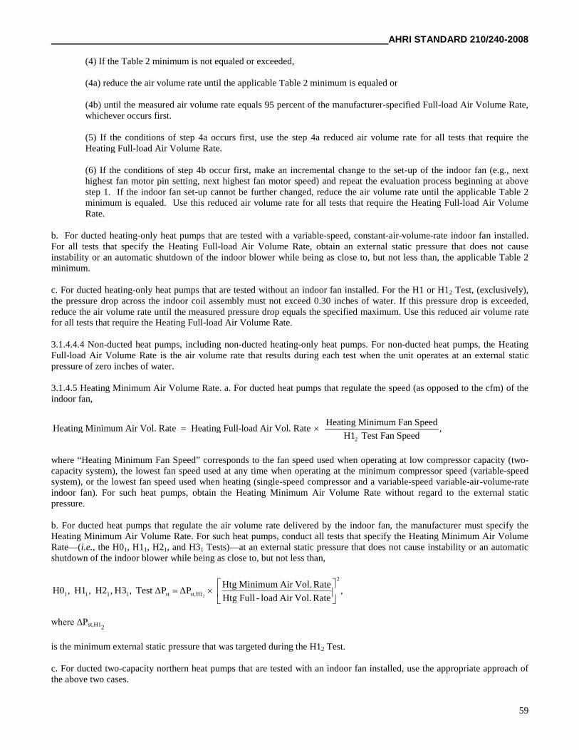
AHRI STANDARD 210/240-2008
59
(4) If the Table 2 minimum is not equaled or exceeded,
(4a) reduce the air volume rate until the applicable Table 2 minimum is equaled or
(4b) until the measured air volume rate equals 95 percent of the manufacturer-specified Full-load Air Volume Rate,whichever occurs first.
(5) If the conditions of step 4a occurs first, use the step 4a reduced air volume rate for all tests that require theHeating Full-load Air Volume Rate.
(6) If the conditions of step 4b occur first, make an incremental change to the set-up of the indoor fan (e.g., nexthighest fan motor pin setting, next highest fan motor speed) and repeat the evaluation process beginning at abovestep 1. If the indoor fan set-up cannot be further changed, reduce the air volume rate until the applicable Table 2minimum is equaled. Use this reduced air volume rate for all tests that require the Heating Full-load Air VolumeRate.
b. For ducted heating-only heat pumps that are tested with a variable-speed, constant-air-volume-rate indoor fan installed.For all tests that specify the Heating Full-load Air Volume Rate, obtain an external static pressure that does not causeinstability or an automatic shutdown of the indoor blower while being as close to, but not less than, the applicable Table 2minimum.
c. For ducted heating-only heat pumps that are tested without an indoor fan installed. For the H1 or H12 Test, (exclusively),the pressure drop across the indoor coil assembly must not exceed 0.30 inches of water. If this pressure drop is exceeded,reduce the air volume rate until the measured pressure drop equals the specified maximum. Use this reduced air volume ratefor all tests that require the Heating Full-load Air Volume Rate.
3.1.4.4.4 Non-ducted heat pumps, including non-ducted heating-only heat pumps. For non-ducted heat pumps, the HeatingFull-load Air Volume Rate is the air volume rate that results during each test when the unit operates at an external staticpressure of zero inches of water.
3.1.4.5 Heating Minimum Air Volume Rate. a. For ducted heat pumps that regulate the speed (as opposed to the cfm) of theindoor fan,
2
Heating Minimum Fan SpeedHeating Minimum Air Vol. Rate Heating Full-load Air Vol. Rate ,
H1 Test Fan Speed
where “Heating Minimum Fan Speed” corresponds to the fan speed used when operating at low compressor capacity (two-capacity system), the lowest fan speed used at any time when operating at the minimum compressor speed (variable-speedsystem), or the lowest fan speed used when heating (single-speed compressor and a variable-speed variable-air-volume-rateindoor fan). For such heat pumps, obtain the Heating Minimum Air Volume Rate without regard to the external staticpressure.
b. For ducted heat pumps that regulate the air volume rate delivered by the indoor fan, the manufacturer must specify theHeating Minimum Air Volume Rate. For such heat pumps, conduct all tests that specify the Heating Minimum Air VolumeRate—(i.e., the H01, H11, H21, and H31 Tests)—at an external static pressure that does not cause instability or an automaticshutdown of the indoor blower while being as close to, but not less than,
,RateVol.Airload-FullHtg
RateVol.AirMinimumHtgPPTest,3H,H2,H1,H0
2
H1st,st1111 2
where ΔPst,H12
is the minimum external static pressure that was targeted during the H12 Test.
c. For ducted two-capacity northern heat pumps that are tested with an indoor fan installed, use the appropriate approach ofthe above two cases.
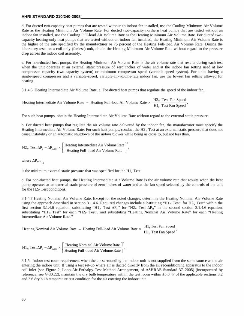
AHRI STANDARD 210/240-2008
60
d. For ducted two-capacity heat pumps that are tested without an indoor fan installed, use the Cooling Minimum Air VolumeRate as the Heating Minimum Air Volume Rate. For ducted two-capacity northern heat pumps that are tested without anindoor fan installed, use the Cooling Full-load Air Volume Rate as the Heating Minimum Air Volume Rate. For ducted two-capacity heating-only heat pumps that are tested without an indoor fan installed, the Heating Minimum Air Volume Rate isthe higher of the rate specified by the manufacturer or 75 percent of the Heating Full-load Air Volume Rate. During thelaboratory tests on a coil-only (fanless) unit, obtain the Heating Minimum Air Volume Rate without regard to the pressuredrop across the indoor coil assembly.
e. For non-ducted heat pumps, the Heating Minimum Air Volume Rate is the air volume rate that results during each testwhen the unit operates at an external static pressure of zero inches of water and at the indoor fan setting used at lowcompressor capacity (two-capacity system) or minimum compressor speed (variable-speed system). For units having asingle-speed compressor and a variable-speed, variable-air-volume-rate indoor fan, use the lowest fan setting allowed forheating.
3.1.4.6 Heating Intermediate Air Volume Rate. a. For ducted heat pumps that regulate the speed of the indoor fan,
V
2
H2 Test Fan SpeedHeating Intermediate Air Volume Rate Heating Full-load Air Volume Rate ,
H1 Test Fan Speed
For such heat pumps, obtain the Heating Intermediate Air Volume Rate without regard to the external static pressure.
b. For ducted heat pumps that regulate the air volume rate delivered by the indoor fan, the manufacturer must specify theHeating Intermediate Air Volume Rate. For such heat pumps, conduct the H2V Test at an external static pressure that does notcause instability or an automatic shutdown of the indoor blower while being as close to, but not less than,
,RateVolumeAirload-FullHeating
RateVolumeAirteIntermediaHeatingPPTestH2
2
H1st,stV 2
where ΔPst,H12
is the minimum external static pressure that was specified for the H12 Test.
c. For non-ducted heat pumps, the Heating Intermediate Air Volume Rate is the air volume rate that results when the heatpump operates at an external static pressure of zero inches of water and at the fan speed selected by the controls of the unitfor the H2V Test conditions.
3.1.4.7 Heating Nominal Air Volume Rate. Except for the noted changes, determine the Heating Nominal Air Volume Rateusing the approach described in section 3.1.4.6. Required changes include substituting “H1N Test” for H2V Test” within thefirst section 3.1.4.6 equation, substituting “H1N Test ΔPst” for “H2V Test ΔPst” in the second section 3.1.4.6 equation,substituting “H1N Test” for each “H2V Test”, and substituting “Heating Nominal Air Volume Rate” for each “HeatingIntermediate Air Volume Rate.”
N
2
H1 Test Fan SpeedHeating Nominal Air Volume Rate Heating Full-load Air Volume Rate ,
H1 Test Fan Speed
,RateVolumeAirload-FullHeating
RateVolumeAirNominalHeatingPPTestH1
2
H1st,stN 2
3.1.5 Indoor test room requirement when the air surrounding the indoor unit is not supplied from the same source as the airentering the indoor unit. If using a test set-up where air is ducted directly from the air reconditioning apparatus to the indoorcoil inlet (see Figure 2, Loop Air-Enthalpy Test Method Arrangement, of ASHRAE Standard 37–2005) (incorporated byreference, see §430.22), maintain the dry bulb temperature within the test room within ±5.0 °F of the applicable sections 3.2and 3.6 dry bulb temperature test condition for the air entering the indoor unit.
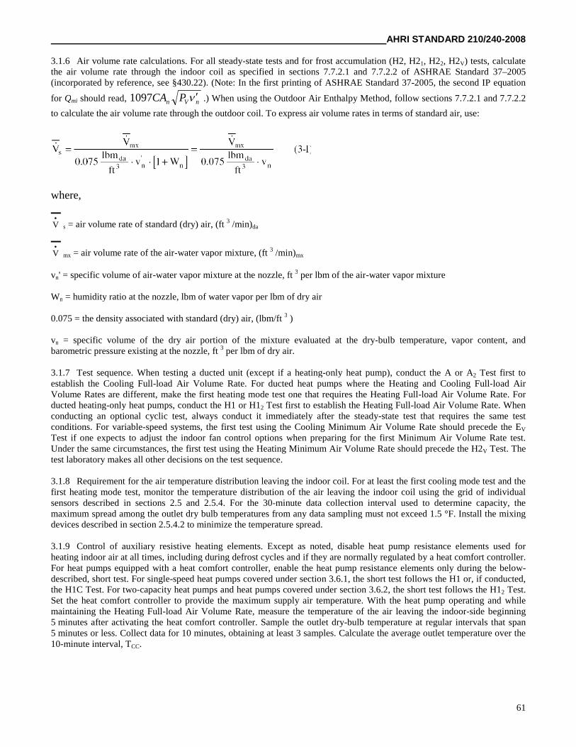
AHRI STANDARD 210/240-2008
61
3.1.6 Air volume rate calculations. For all steady-state tests and for frost accumulation (H2, H21, H22, H2V) tests, calculatethe air volume rate through the indoor coil as specified in sections 7.7.2.1 and 7.7.2.2 of ASHRAE Standard 37–2005(incorporated by reference, see §430.22). (Note: In the first printing of ASHRAE Standard 37-2005, the second IP equation
for Qmi should read, nVn PCA 1097 .) When using the Outdoor Air Enthalpy Method, follow sections 7.7.2.1 and 7.7.2.2
to calculate the air volume rate through the outdoor coil. To express air volume rates in terms of standard air, use:
where,
V
s = air volume rate of standard (dry) air, (ft 3 /min)da
V
mx = air volume rate of the air-water vapor mixture, (ft 3 /min)mx
vn' = specific volume of air-water vapor mixture at the nozzle, ft 3 per lbm of the air-water vapor mixture
Wn = humidity ratio at the nozzle, lbm of water vapor per lbm of dry air
0.075 = the density associated with standard (dry) air, (lbm/ft 3 )
vn = specific volume of the dry air portion of the mixture evaluated at the dry-bulb temperature, vapor content, andbarometric pressure existing at the nozzle, ft 3 per lbm of dry air.
3.1.7 Test sequence. When testing a ducted unit (except if a heating-only heat pump), conduct the A or A2 Test first toestablish the Cooling Full-load Air Volume Rate. For ducted heat pumps where the Heating and Cooling Full-load AirVolume Rates are different, make the first heating mode test one that requires the Heating Full-load Air Volume Rate. Forducted heating-only heat pumps, conduct the H1 or H12 Test first to establish the Heating Full-load Air Volume Rate. Whenconducting an optional cyclic test, always conduct it immediately after the steady-state test that requires the same testconditions. For variable-speed systems, the first test using the Cooling Minimum Air Volume Rate should precede the EV
Test if one expects to adjust the indoor fan control options when preparing for the first Minimum Air Volume Rate test.Under the same circumstances, the first test using the Heating Minimum Air Volume Rate should precede the H2V Test. Thetest laboratory makes all other decisions on the test sequence.
3.1.8 Requirement for the air temperature distribution leaving the indoor coil. For at least the first cooling mode test and thefirst heating mode test, monitor the temperature distribution of the air leaving the indoor coil using the grid of individualsensors described in sections 2.5 and 2.5.4. For the 30-minute data collection interval used to determine capacity, themaximum spread among the outlet dry bulb temperatures from any data sampling must not exceed 1.5 °F. Install the mixingdevices described in section 2.5.4.2 to minimize the temperature spread.
3.1.9 Control of auxiliary resistive heating elements. Except as noted, disable heat pump resistance elements used forheating indoor air at all times, including during defrost cycles and if they are normally regulated by a heat comfort controller.For heat pumps equipped with a heat comfort controller, enable the heat pump resistance elements only during the below-described, short test. For single-speed heat pumps covered under section 3.6.1, the short test follows the H1 or, if conducted,the H1C Test. For two-capacity heat pumps and heat pumps covered under section 3.6.2, the short test follows the H12 Test.Set the heat comfort controller to provide the maximum supply air temperature. With the heat pump operating and whilemaintaining the Heating Full-load Air Volume Rate, measure the temperature of the air leaving the indoor-side beginning5 minutes after activating the heat comfort controller. Sample the outlet dry-bulb temperature at regular intervals that span5 minutes or less. Collect data for 10 minutes, obtaining at least 3 samples. Calculate the average outlet temperature over the10-minute interval, TCC.
AHRI STANDARD 210/240-2008
62
3.2 Cooling mode tests for different types of air conditioners and heat pumps.
3.2.1 Tests for a unit having a single-speed compressor that is tested with a fixed-speed indoor fan installed, with a constant-air-volume-rate indoor fan installed, or with no indoor fan installed. Conduct two steady-state wet coil tests, the A and BTests. Use the two optional dry-coil tests, the steady-state C Test and the cyclic D Test, to determine the cooling mode cyclicdegradation coefficient, CD
c. If the two optional tests are conducted but yield a tested CDc that exceeds the default CD
c of if thetwo optional tests are not conducted, assign CD
c the default value of 0.25. Table 3 specifies test conditions for these four tests.
3.2.2 Tests for a unit having a single-speed compressor and a variable-speed variable-air-volume-rate indoor fan installed.
3.2.2.1 Indoor fan capacity modulation that correlates with the outdoor dry bulb temperature. Conduct four steady-state wetcoil tests: The A2, A1 , B2, and B1 Tests. Use the two optional dry-coil tests, the steady-state C1 Test and the cyclic D1 Test, to
determine the cooling mode cyclic-degradation coefficient,cDC . If the two optional tests are conducted but yield a tested
cDC that exceeds the default
cDC or if the two optional tests are not conducted, assign
cDC the default value of 0.25. Table 4
specifies test conditions for these six tests
3.2.2.2 Indoor fan capacity modulation based on adjusting the sensible to total (S/T) cooling capacity ratio. The testingrequirements are the same as specified in section 3.2.1 and Table 3. Use a Cooling Full-load Air Volume Rate that representsa normal residential installation. If performed, conduct the steady-state C Test and the cyclic D Test with the unit operating inthe same S/T capacity control mode as used for the B Test.
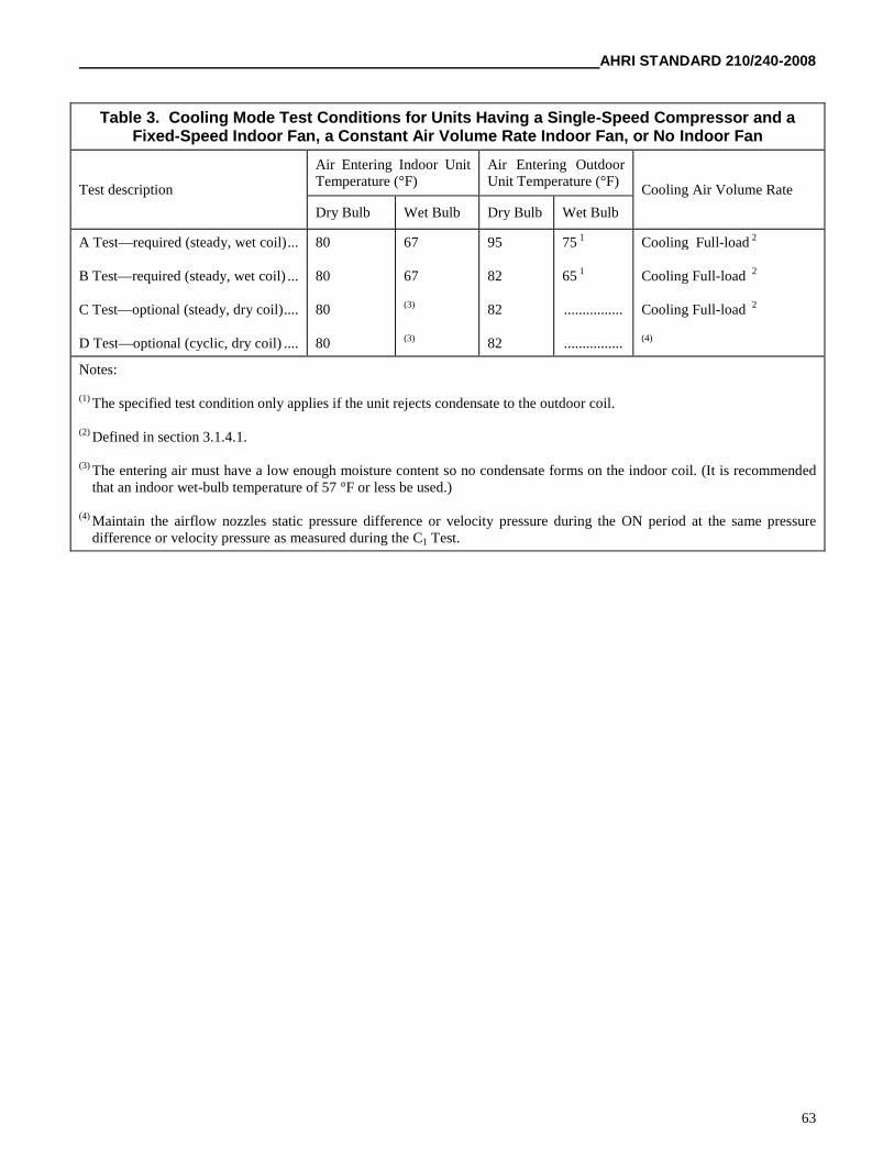
AHRI STANDARD 210/240-2008
63
Table 3. Cooling Mode Test Conditions for Units Having a Single-Speed Compressor and aFixed-Speed Indoor Fan, a Constant Air Volume Rate Indoor Fan, or No Indoor Fan
Test description
Air Entering Indoor UnitTemperature (°F)
Air Entering OutdoorUnit Temperature (°F)
Cooling Air Volume Rate
Dry Bulb Wet Bulb Dry Bulb Wet Bulb
A Test—required (steady, wet coil)...
B Test—required (steady, wet coil) ...
C Test—optional (steady, dry coil)....
D Test—optional (cyclic, dry coil) ....
80
80
80
80
67
67
(3)
(3)
95
82
82
82
75 1
65 1
................
................
Cooling Full-load 2
Cooling Full-load 2
Cooling Full-load 2
(4)
Notes:
(1) The specified test condition only applies if the unit rejects condensate to the outdoor coil.
(2) Defined in section 3.1.4.1.
(3) The entering air must have a low enough moisture content so no condensate forms on the indoor coil. (It is recommendedthat an indoor wet-bulb temperature of 57 °F or less be used.)
(4) Maintain the airflow nozzles static pressure difference or velocity pressure during the ON period at the same pressuredifference or velocity pressure as measured during the C1 Test.
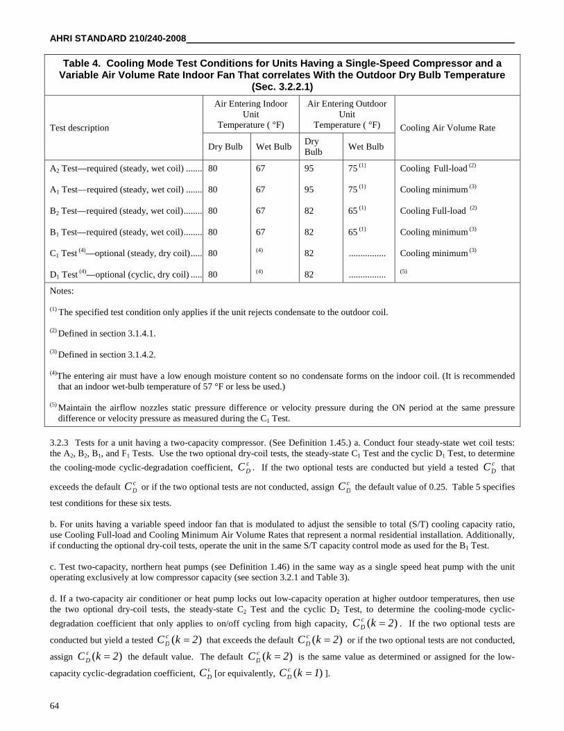
AHRI STANDARD 210/240-2008
64
Table 4. Cooling Mode Test Conditions for Units Having a Single-Speed Compressor and aVariable Air Volume Rate Indoor Fan That correlates With the Outdoor Dry Bulb Temperature
(Sec. 3.2.2.1)
Test description
Air Entering IndoorUnit
Temperature ( °F)
Air Entering OutdoorUnit
Temperature ( °F) Cooling Air Volume Rate
Dry Bulb Wet BulbDryBulb
Wet Bulb
A2 Test—required (steady, wet coil) ...........
A1 Test—required (steady, wet coil) ...........
B2 Test—required (steady, wet coil)............
B1 Test—required (steady, wet coil)............
C1 Test (4)—optional (steady, dry coil).........
D1 Test (4)—optional (cyclic, dry coil) .........
80
80
80
80
80
80
67
67
67
67
(4)
(4)
95
95
82
82
82
82
75 (1)
75 (1)
65 (1)
65 (1)
................
................
Cooling Full-load (2)
Cooling minimum (3)
Cooling Full-load (2)
Cooling minimum (3)
Cooling minimum (3)
(5)
Notes:
(1) The specified test condition only applies if the unit rejects condensate to the outdoor coil.
(2) Defined in section 3.1.4.1.
(3) Defined in section 3.1.4.2.
(4)The entering air must have a low enough moisture content so no condensate forms on the indoor coil. (It is recommendedthat an indoor wet-bulb temperature of 57 °F or less be used.)
(5) Maintain the airflow nozzles static pressure difference or velocity pressure during the ON period at the same pressuredifference or velocity pressure as measured during the C1 Test.
3.2.3 Tests for a unit having a two-capacity compressor. (See Definition 1.45.) a. Conduct four steady-state wet coil tests:the A2, B2, B1, and F1 Tests. Use the two optional dry-coil tests, the steady-state C1 Test and the cyclic D1 Test, to determine
the cooling-mode cyclic-degradation coefficient,cDC . If the two optional tests are conducted but yield a tested
cDC that
exceeds the defaultcDC or if the two optional tests are not conducted, assign
cDC the default value of 0.25. Table 5 specifies
test conditions for these six tests.
b. For units having a variable speed indoor fan that is modulated to adjust the sensible to total (S/T) cooling capacity ratio,use Cooling Full-load and Cooling Minimum Air Volume Rates that represent a normal residential installation. Additionally,if conducting the optional dry-coil tests, operate the unit in the same S/T capacity control mode as used for the B1 Test.
c. Test two-capacity, northern heat pumps (see Definition 1.46) in the same way as a single speed heat pump with the unitoperating exclusively at low compressor capacity (see section 3.2.1 and Table 3).
d. If a two-capacity air conditioner or heat pump locks out low-capacity operation at higher outdoor temperatures, then usethe two optional dry-coil tests, the steady-state C2 Test and the cyclic D2 Test, to determine the cooling-mode cyclic-
degradation coefficient that only applies to on/off cycling from high capacity, )( 2kC cD . If the two optional tests are
conducted but yield a tested )( 2kC cD that exceeds the default )( 2kC c
D or if the two optional tests are not conducted,
assign )( 2kC cD the default value. The default )( 2kC c
D is the same value as determined or assigned for the low-
capacity cyclic-degradation coefficient,cDC [or equivalently, )( 1kC c
D ].

AHRI STANDARD 210/240-2008
65
Table 5. Cooling Mode Test Conditions for UnitsHaving a Two-Capacity Compressor
Test Description
Air EnteringIndoor Unit
Temperature (F)
Air EnteringOutdoor Unit
Temperature (F)CompressorCapacity
Cooling AirVolume Rate
DryBulb
WetBulb
DryBulb
WetBulb
A2 Test – required
(steady, wet coil)80 67 95 75(1) High
Cooling Full-Load2)
B2 Test – required
(steady, wet coil)80 67 82 65(1) High
Cooling Full-Load2)
B1 Test – required
(steady, wet coil)80 67 82 65(1) Low
CoolingMinimum(3)
C2 Test – optional
(steady, dry-coil)80 (4) 82 High
Cooling Full-Load(2)
D2 Test – optional
(cyclic, dry-coil)80 (4) 82 High (5)
C1 Test – optional
(steady, dry-coil)80 (4) 82 Low
CoolingMinimum(3)
D1 Test – optional
(cyclic, dry-coil)80 (4) 82 Low (6)
F1 Test – required
(steady, wet coil)80 67 67 53.5(1) Low
CoolingMinimum(3)
(1) The specified test condition only applies if the unit rejects condensate to the outdoor coil.
(2) Defined in section 3.1.4.1.
(3) Defined in section 3.1.4.2.
(4) The entering air must have a low enough moisture content so no condensate forms on the indoorcoil. DOE recommends using an indoor air wet-bulb temperature of 57F or less.
(5) Maintain the airflow nozzle(s) static pressure difference or velocity pressure during the ON periodat the same pressure or velocity as measured during the C2 Test.
(6) Maintain the airflow nozzle(s) static pressure difference or velocity pressure during the ON periodat the same pressure or velocity as measured during the C1 Test.
3.2.4 Tests for a unit having a variable-speed compressor. a. Conduct five steady-state wet coil tests: The A2, EV, B2, B1,and F1 tests. Use the two optional dry-coil tests, the steady-state G1 Test and the cyclic I1 Test, to determine the cooling mode
cyclic-degradation coefficient,cDC . If the two optional tests are conducted but yield a tested
cDC that exceeds the default
cDC or if the two optional tests are not conducted, assign
cDC the default value of 0.25. Table 6 specifies test conditions for
these seven tests. Determine the intermediate compressor speed cited in Table 6 using:
AHRI STANDARD 210/240-2008
66
where a tolerance of plus 5 percent or the next higher inverter frequency step from that calculated is allowed.
b. For units that modulate the indoor fan speed to adjust the sensible to total (S/T) cooling capacity ratio, use Cooling Full-load, Cooling Intermediate, and Cooling Minimum Air Volume Rates that represent a normal residential installation.Additionally, if conducting the optional dry-coil tests, operate the unit in the same S/T capacity control mode as used for theF1 Test.
c. For multiple-split air conditioners and heat pumps (except where noted), the following procedures supersede the aboverequirements: For all Table 6 tests specified for a minimum compressor speed, at least one indoor unit must be turned off.The manufacturer shall designate the particular indoor unit(s) that is turned off. The manufacturer must also specify thecompressor speed used for the Table 6 EV Test, a cooling-mode intermediate compressor speed that falls within ¼ and ¾ ofthe difference between the maximum and minimum cooling-mode speeds. The manufacturer should prescribe anintermediate speed that is expected to yield the highest EER for the given EV Test conditions and bracketed compressor speedrange. The manufacturer can designate that one or more indoor units are turned off for the EV Test.
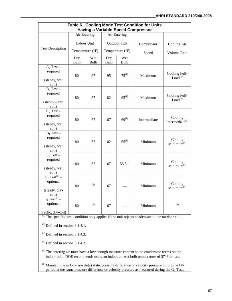
AHRI STANDARD 210/240-2008
67
Table 6. Cooling Mode Test Condition for UnitsHaving a Variable-Speed Compressor
Test Description
Air Entering
Indoor Unit
Air Entering
Outdoor Unit Compressor
Speed
Cooling Air
Volume RateTemperature (F) Temperature (F)
DryBulb
WetBulb
DryBulb
WetBulb
A2 Test –required
(steady, wetcoil)
80 67 95 75(1) MaximumCooling Full-
Load(2)
B2 Test –required
(steady – wetcoil)
80 67 82 65(1) MaximumCooling Full-
Load(2)
EV Test –required
(steady, wetcoil)
80 67 87 69(1) IntermediateCooling
Intermediate(3)
B1 Test –required
(steady, wetcoil)
80 67 82 65(1) MinimumCooling
Minimum(4)
F1 Test –required
(steady, wetcoil)
80 67 67 53.5(1) MinimumCooling
Minimum(4)
G1 Test(5) –optional
(steady, dry-coil)
80 (6) 67 MinimumCooling
Minimum(4)
I1 Test(5) –optional
(cyclic, dry-coil)
80 (6) 67 Minimum (6)
(1) The specified test condition only applies if the unit rejects condensate to the outdoor coil.
(2) Defined in section 3.1.4.1.
(3) Defined in section 3.1.4.3.
(4) Defined in section 3.1.4.2.
(5) The entering air must have a low enough moisture content so no condensate forms on theindoor coil. DOE recommends using an indoor air wet bulb temperature of 57F or less.
(6) Maintain the airflow nozzle(s) static pressure difference or velocity pressure during the ONperiod at the same pressure difference or velocity pressure as measured during the G1 Test.
AHRI STANDARD 210/240-2008
68
3.3 Test procedures for steady-state wet coil cooling mode tests (the A, A2, A1, B, B2, B1, EV, and F1 Tests). a. For thepretest interval, operate the test room reconditioning apparatus and the unit to be tested until maintaining equilibriumconditions for at least 30 minutes at the specified section 3.2 test conditions. Use the exhaust fan of the airflow measuringapparatus and, if installed, the indoor fan of the test unit to obtain and then maintain the indoor air volume rate and/orexternal static pressure specified for the particular test. Continuously record (see Definition 1.15):
(1) The dry-bulb temperature of the air entering the indoor coil,
(2) The water vapor content of the air entering the indoor coil,
(3) The dry-bulb temperature of the air entering the outdoor coil, and
(4) For the section 2.2.4 cases where its control is required, the water vapor content of the air entering the outdoor coil.
Refer to section 3.11 for additional requirements that depend on the selected secondary test method.
b. After satisfying the pretest equilibrium requirements, make the measurements specified in Table 3 of ASHRAE Standard37–2005 (incorporated by reference, see §430.22) for the Indoor Air Enthalpy method and the user-selected secondarymethod. Except for external static pressure, make the Table 3 measurements at equal intervals that span 10 minutes or less.Measure external static pressure every 5 minutes or less. Continue data sampling until reaching a 30-minute period (e.g., fourconsecutive 10-minute samples) where the test tolerances specified in Table 7 are satisfied. For those continuously recordedparameters, use the entire data set from the 30-minute interval to evaluate Table 7 compliance. Determine the averageelectrical power consumption of the air conditioner or heat pump over the same 30-minute interval.
c. Calculate indoor-side total cooling capacity as specified in sections 7.3.3.1 and 7.3.3.3 of ASHRAE Standard 37–2005(incorporated by reference, see §430.22). Do not adjust the parameters used in calculating capacity for the permittedvariations in test conditions. Evaluate air enthalpies based on the measured barometric pressure. Assign the average total
space cooling capacity and electrical power consumption over the 30-minute data collection interval to the variables Q
ck(T)
and E
ck(T), respectively. For these two variables, replace the “T” with the nominal outdoor temperature at which the test
was conducted. The superscript k is used only when testing multi-capacity units. Use the superscript k=2 to denote a test withthe unit operating at high capacity or maximum speed, k=1 to denote low capacity or minimum speed, and k=v to denote theintermediate speed.
d. For units tested without an indoor fan installed, decrease Q
ck(T) by
and increase E
ck(T) by,
where V
s is the average measured indoor air volume rate expressed in units of cubic feet per minute of standard air (scfm).
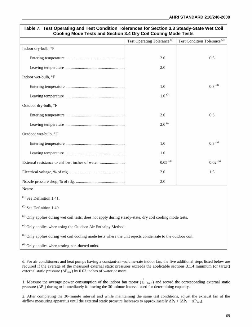
AHRI STANDARD 210/240-2008
69
Table 7. Test Operating and Test Condition Tolerances for Section 3.3 Steady-State Wet CoilCooling Mode Tests and Section 3.4 Dry Coil Cooling Mode Tests
Test Operating Tolerance (1) Test Condition Tolerance (2)
Indoor dry-bulb, °F
Entering temperature .........................................................
Leaving temperature ..........................................................
Indoor wet-bulb, °F
Entering temperature .........................................................
Leaving temperature ..........................................................
Outdoor dry-bulb, °F
Entering temperature .........................................................
Leaving temperature ..........................................................
Outdoor wet-bulb, °F
Entering temperature .........................................................
Leaving temperature ..........................................................
External resistance to airflow, inches of water .........................
Electrical voltage, % of rdg. .....................................................
Nozzle pressure drop, % of rdg. ................................................
2.0
2.0
1.0
1.0 (3)
2.0
2.0 (4)
1.0
1.0
0.05 (4)
2.0
2.0
0.5
0.3 (3)
0.5
0.3 (5)
0.02 (6)
1.5
Notes:
(1) See Definition 1.41.
(2) See Definition 1.40.
(3) Only applies during wet coil tests; does not apply during steady-state, dry coil cooling mode tests.
(4) Only applies when using the Outdoor Air Enthalpy Method.
(5) Only applies during wet coil cooling mode tests where the unit rejects condensate to the outdoor coil.
(6) Only applies when testing non-ducted units.
d. For air conditioners and heat pumps having a constant-air-volume-rate indoor fan, the five additional steps listed below arerequired if the average of the measured external static pressures exceeds the applicable sections 3.1.4 minimum (or target)external static pressure (ΔPmin) by 0.03 inches of water or more.
1. Measure the average power consumption of the indoor fan motor ( E
fan,1) and record the corresponding external staticpressure (ΔP1) during or immediately following the 30-minute interval used for determining capacity.
2. After completing the 30-minute interval and while maintaining the same test conditions, adjust the exhaust fan of theairflow measuring apparatus until the external static pressure increases to approximately ΔP1 + (ΔP1 − ΔPmin).
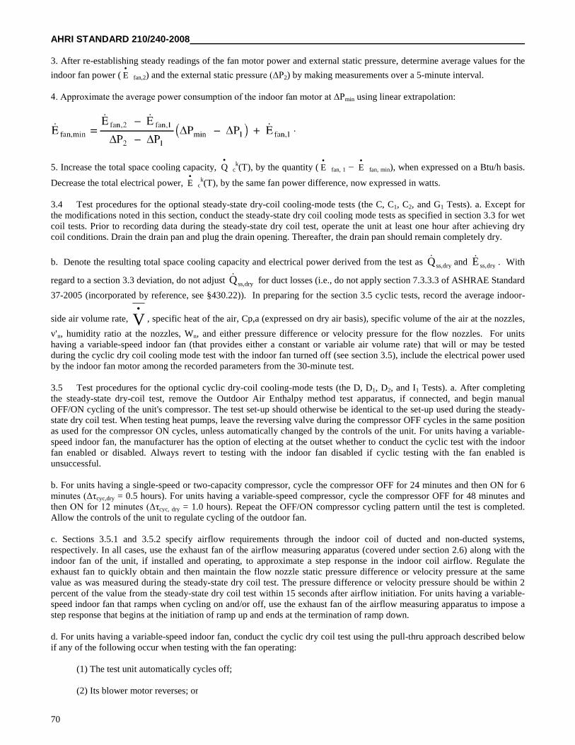
AHRI STANDARD 210/240-2008
70
3. After re-establishing steady readings of the fan motor power and external static pressure, determine average values for the
indoor fan power ( E
fan,2) and the external static pressure (ΔP2) by making measurements over a 5-minute interval.
4. Approximate the average power consumption of the indoor fan motor at ΔPmin using linear extrapolation:
5. Increase the total space cooling capacity, Q
ck(T), by the quantity ( E
fan, 1 − E
fan, min), when expressed on a Btu/h basis.
Decrease the total electrical power, E
ck(T), by the same fan power difference, now expressed in watts.
3.4 Test procedures for the optional steady-state dry-coil cooling-mode tests (the C, C1, C2, and G1 Tests). a. Except forthe modifications noted in this section, conduct the steady-state dry coil cooling mode tests as specified in section 3.3 for wetcoil tests. Prior to recording data during the steady-state dry coil test, operate the unit at least one hour after achieving drycoil conditions. Drain the drain pan and plug the drain opening. Thereafter, the drain pan should remain completely dry.
b. Denote the resulting total space cooling capacity and electrical power derived from the test as dryss,Q and dryss,E . With
regard to a section 3.3 deviation, do not adjust dryss,Q for duct losses (i.e., do not apply section 7.3.3.3 of ASHRAE Standard
37-2005 (incorporated by reference, see §430.22)). In preparing for the section 3.5 cyclic tests, record the average indoor-
side air volume rate, V
, specific heat of the air, Cp,a (expressed on dry air basis), specific volume of the air at the nozzles,
v'n, humidity ratio at the nozzles, Wn, and either pressure difference or velocity pressure for the flow nozzles. For unitshaving a variable-speed indoor fan (that provides either a constant or variable air volume rate) that will or may be testedduring the cyclic dry coil cooling mode test with the indoor fan turned off (see section 3.5), include the electrical power usedby the indoor fan motor among the recorded parameters from the 30-minute test.
3.5 Test procedures for the optional cyclic dry-coil cooling-mode tests (the D, D1, D2, and I1 Tests). a. After completingthe steady-state dry-coil test, remove the Outdoor Air Enthalpy method test apparatus, if connected, and begin manualOFF/ON cycling of the unit's compressor. The test set-up should otherwise be identical to the set-up used during the steady-state dry coil test. When testing heat pumps, leave the reversing valve during the compressor OFF cycles in the same positionas used for the compressor ON cycles, unless automatically changed by the controls of the unit. For units having a variable-speed indoor fan, the manufacturer has the option of electing at the outset whether to conduct the cyclic test with the indoorfan enabled or disabled. Always revert to testing with the indoor fan disabled if cyclic testing with the fan enabled isunsuccessful.
b. For units having a single-speed or two-capacity compressor, cycle the compressor OFF for 24 minutes and then ON for 6minutes (Δτcyc,dry = 0.5 hours). For units having a variable-speed compressor, cycle the compressor OFF for 48 minutes andthen ON for 12 minutes (Δτcyc, dry = 1.0 hours). Repeat the OFF/ON compressor cycling pattern until the test is completed.Allow the controls of the unit to regulate cycling of the outdoor fan.
c. Sections 3.5.1 and 3.5.2 specify airflow requirements through the indoor coil of ducted and non-ducted systems,respectively. In all cases, use the exhaust fan of the airflow measuring apparatus (covered under section 2.6) along with theindoor fan of the unit, if installed and operating, to approximate a step response in the indoor coil airflow. Regulate theexhaust fan to quickly obtain and then maintain the flow nozzle static pressure difference or velocity pressure at the samevalue as was measured during the steady-state dry coil test. The pressure difference or velocity pressure should be within 2percent of the value from the steady-state dry coil test within 15 seconds after airflow initiation. For units having a variable-speed indoor fan that ramps when cycling on and/or off, use the exhaust fan of the airflow measuring apparatus to impose astep response that begins at the initiation of ramp up and ends at the termination of ramp down.
d. For units having a variable-speed indoor fan, conduct the cyclic dry coil test using the pull-thru approach described belowif any of the following occur when testing with the fan operating:
(1) The test unit automatically cycles off;
(2) Its blower motor reverses; or
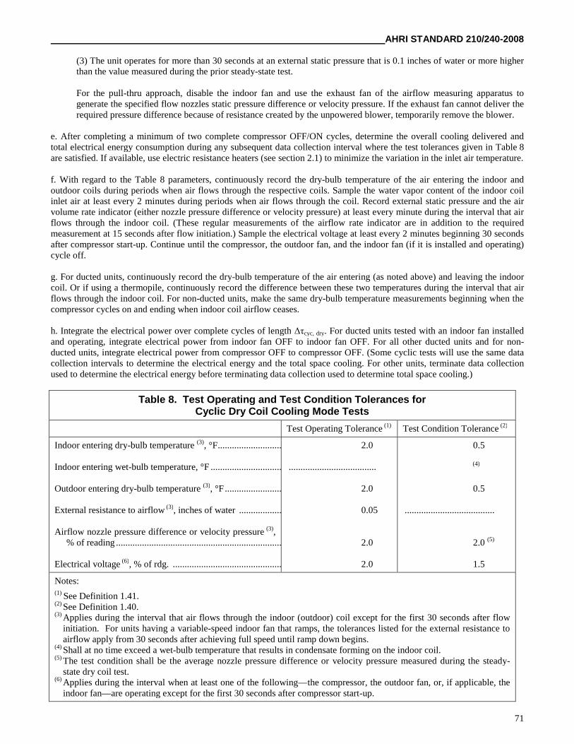
AHRI STANDARD 210/240-2008
71
(3) The unit operates for more than 30 seconds at an external static pressure that is 0.1 inches of water or more higherthan the value measured during the prior steady-state test.
For the pull-thru approach, disable the indoor fan and use the exhaust fan of the airflow measuring apparatus togenerate the specified flow nozzles static pressure difference or velocity pressure. If the exhaust fan cannot deliver therequired pressure difference because of resistance created by the unpowered blower, temporarily remove the blower.
e. After completing a minimum of two complete compressor OFF/ON cycles, determine the overall cooling delivered andtotal electrical energy consumption during any subsequent data collection interval where the test tolerances given in Table 8are satisfied. If available, use electric resistance heaters (see section 2.1) to minimize the variation in the inlet air temperature.
f. With regard to the Table 8 parameters, continuously record the dry-bulb temperature of the air entering the indoor andoutdoor coils during periods when air flows through the respective coils. Sample the water vapor content of the indoor coilinlet air at least every 2 minutes during periods when air flows through the coil. Record external static pressure and the airvolume rate indicator (either nozzle pressure difference or velocity pressure) at least every minute during the interval that airflows through the indoor coil. (These regular measurements of the airflow rate indicator are in addition to the requiredmeasurement at 15 seconds after flow initiation.) Sample the electrical voltage at least every 2 minutes beginning 30 secondsafter compressor start-up. Continue until the compressor, the outdoor fan, and the indoor fan (if it is installed and operating)cycle off.
g. For ducted units, continuously record the dry-bulb temperature of the air entering (as noted above) and leaving the indoorcoil. Or if using a thermopile, continuously record the difference between these two temperatures during the interval that airflows through the indoor coil. For non-ducted units, make the same dry-bulb temperature measurements beginning when thecompressor cycles on and ending when indoor coil airflow ceases.
h. Integrate the electrical power over complete cycles of length Δτcyc, dry. For ducted units tested with an indoor fan installedand operating, integrate electrical power from indoor fan OFF to indoor fan OFF. For all other ducted units and for non-ducted units, integrate electrical power from compressor OFF to compressor OFF. (Some cyclic tests will use the same datacollection intervals to determine the electrical energy and the total space cooling. For other units, terminate data collectionused to determine the electrical energy before terminating data collection used to determine total space cooling.)
Table 8. Test Operating and Test Condition Tolerances forCyclic Dry Coil Cooling Mode Tests
Test Operating Tolerance (1) Test Condition Tolerance (2)
Indoor entering dry-bulb temperature (3), °F...............................
Indoor entering wet-bulb temperature, °F ................................
Outdoor entering dry-bulb temperature (3), °F ............................
External resistance to airflow (3), inches of water ......................
Airflow nozzle pressure difference or velocity pressure (3),% of reading ..........................................................................
Electrical voltage (6), % of rdg. ..................................................
2.0
.....................................
2.0
0.05
2.0
2.0
0.5
(4)
0.5
......................................
2.0 (5)
1.5
Notes:(1) See Definition 1.41.(2) See Definition 1.40.(3) Applies during the interval that air flows through the indoor (outdoor) coil except for the first 30 seconds after flow
initiation. For units having a variable-speed indoor fan that ramps, the tolerances listed for the external resistance toairflow apply from 30 seconds after achieving full speed until ramp down begins.
(4) Shall at no time exceed a wet-bulb temperature that results in condensate forming on the indoor coil.(5) The test condition shall be the average nozzle pressure difference or velocity pressure measured during the steady-
state dry coil test.(6) Applies during the interval when at least one of the following—the compressor, the outdoor fan, or, if applicable, the
indoor fan—are operating except for the first 30 seconds after compressor start-up.
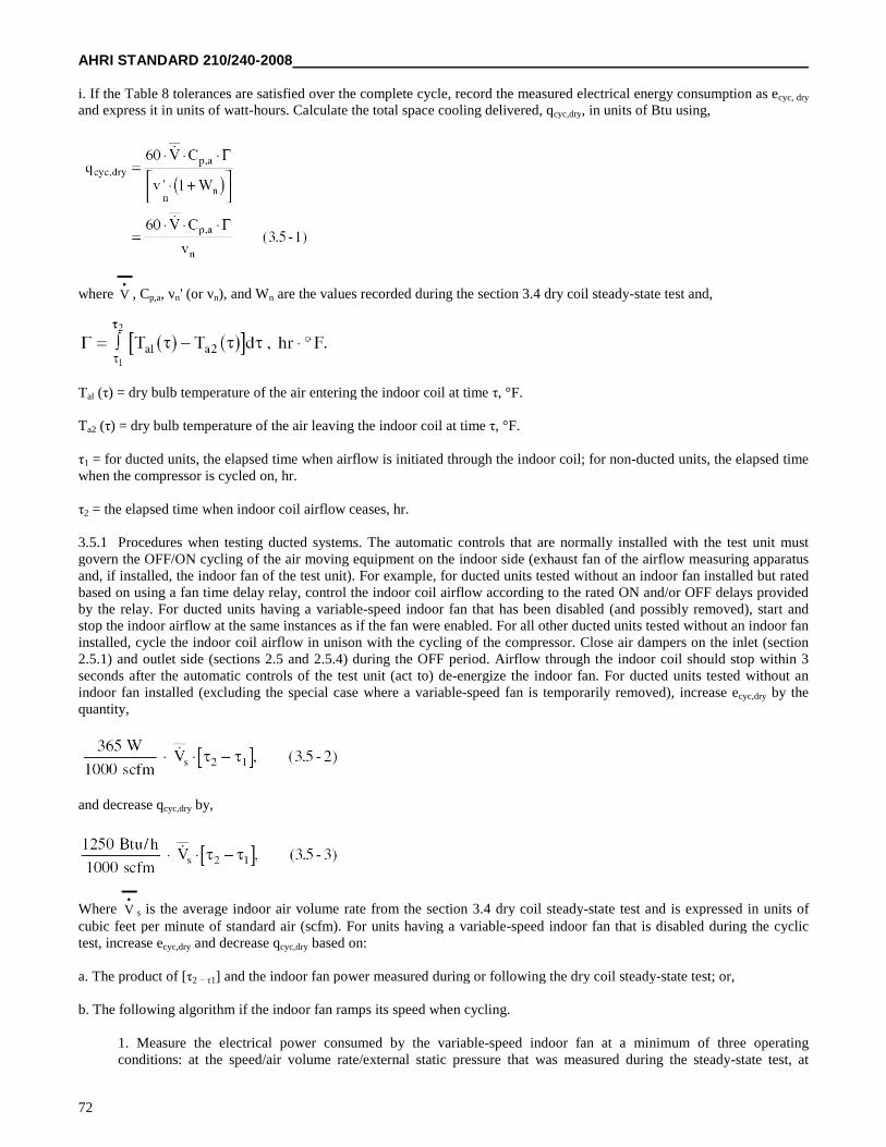
AHRI STANDARD 210/240-2008
72
i. If the Table 8 tolerances are satisfied over the complete cycle, record the measured electrical energy consumption as ecyc, dry
and express it in units of watt-hours. Calculate the total space cooling delivered, qcyc,dry, in units of Btu using,
where V
, Cp,a, vn' (or vn), and Wn are the values recorded during the section 3.4 dry coil steady-state test and,
Tal (τ) = dry bulb temperature of the air entering the indoor coil at time τ, °F.
Ta2 (τ) = dry bulb temperature of the air leaving the indoor coil at time τ, °F.
τ1 = for ducted units, the elapsed time when airflow is initiated through the indoor coil; for non-ducted units, the elapsed timewhen the compressor is cycled on, hr.
τ2 = the elapsed time when indoor coil airflow ceases, hr.
3.5.1 Procedures when testing ducted systems. The automatic controls that are normally installed with the test unit mustgovern the OFF/ON cycling of the air moving equipment on the indoor side (exhaust fan of the airflow measuring apparatusand, if installed, the indoor fan of the test unit). For example, for ducted units tested without an indoor fan installed but ratedbased on using a fan time delay relay, control the indoor coil airflow according to the rated ON and/or OFF delays providedby the relay. For ducted units having a variable-speed indoor fan that has been disabled (and possibly removed), start andstop the indoor airflow at the same instances as if the fan were enabled. For all other ducted units tested without an indoor faninstalled, cycle the indoor coil airflow in unison with the cycling of the compressor. Close air dampers on the inlet (section2.5.1) and outlet side (sections 2.5 and 2.5.4) during the OFF period. Airflow through the indoor coil should stop within 3seconds after the automatic controls of the test unit (act to) de-energize the indoor fan. For ducted units tested without anindoor fan installed (excluding the special case where a variable-speed fan is temporarily removed), increase ecyc,dry by thequantity,
and decrease qcyc,dry by,
Where V
s is the average indoor air volume rate from the section 3.4 dry coil steady-state test and is expressed in units ofcubic feet per minute of standard air (scfm). For units having a variable-speed indoor fan that is disabled during the cyclictest, increase ecyc,dry and decrease qcyc,dry based on:
a. The product of [τ2 − τ1] and the indoor fan power measured during or following the dry coil steady-state test; or,
b. The following algorithm if the indoor fan ramps its speed when cycling.
1. Measure the electrical power consumed by the variable-speed indoor fan at a minimum of three operatingconditions: at the speed/air volume rate/external static pressure that was measured during the steady-state test, at
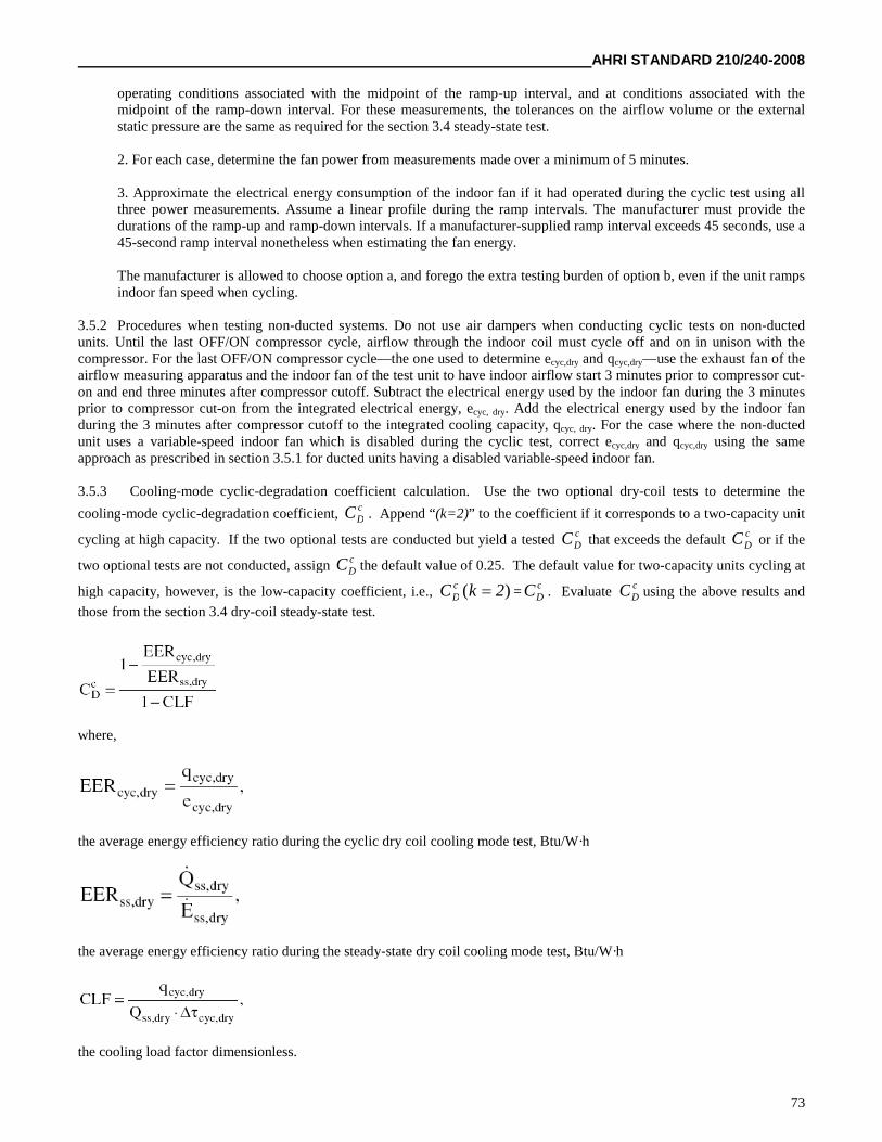
AHRI STANDARD 210/240-2008
73
operating conditions associated with the midpoint of the ramp-up interval, and at conditions associated with themidpoint of the ramp-down interval. For these measurements, the tolerances on the airflow volume or the externalstatic pressure are the same as required for the section 3.4 steady-state test.
2. For each case, determine the fan power from measurements made over a minimum of 5 minutes.
3. Approximate the electrical energy consumption of the indoor fan if it had operated during the cyclic test using allthree power measurements. Assume a linear profile during the ramp intervals. The manufacturer must provide thedurations of the ramp-up and ramp-down intervals. If a manufacturer-supplied ramp interval exceeds 45 seconds, use a45-second ramp interval nonetheless when estimating the fan energy.
The manufacturer is allowed to choose option a, and forego the extra testing burden of option b, even if the unit rampsindoor fan speed when cycling.
3.5.2 Procedures when testing non-ducted systems. Do not use air dampers when conducting cyclic tests on non-ductedunits. Until the last OFF/ON compressor cycle, airflow through the indoor coil must cycle off and on in unison with thecompressor. For the last OFF/ON compressor cycle—the one used to determine ecyc,dry and qcyc,dry—use the exhaust fan of theairflow measuring apparatus and the indoor fan of the test unit to have indoor airflow start 3 minutes prior to compressor cut-on and end three minutes after compressor cutoff. Subtract the electrical energy used by the indoor fan during the 3 minutesprior to compressor cut-on from the integrated electrical energy, ecyc, dry. Add the electrical energy used by the indoor fanduring the 3 minutes after compressor cutoff to the integrated cooling capacity, qcyc, dry. For the case where the non-ductedunit uses a variable-speed indoor fan which is disabled during the cyclic test, correct ecyc,dry and qcyc,dry using the sameapproach as prescribed in section 3.5.1 for ducted units having a disabled variable-speed indoor fan.
3.5.3 Cooling-mode cyclic-degradation coefficient calculation. Use the two optional dry-coil tests to determine the
cooling-mode cyclic-degradation coefficient,cDC . Append “(k=2)” to the coefficient if it corresponds to a two-capacity unit
cycling at high capacity. If the two optional tests are conducted but yield a testedcDC that exceeds the default
cDC or if the
two optional tests are not conducted, assigncDC the default value of 0.25. The default value for two-capacity units cycling at
high capacity, however, is the low-capacity coefficient, i.e., )( 2kC cD =
cDC . Evaluate
cDC using the above results and
those from the section 3.4 dry-coil steady-state test.
where,
the average energy efficiency ratio during the cyclic dry coil cooling mode test, Btu/W·h
the average energy efficiency ratio during the steady-state dry coil cooling mode test, Btu/W·h
the cooling load factor dimensionless.
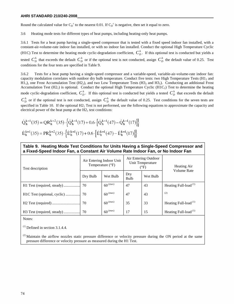
AHRI STANDARD 210/240-2008
74
Round the calculated value for CDc to the nearest 0.01. If CD
c is negative, then set it equal to zero.
3.6 Heating mode tests for different types of heat pumps, including heating-only heat pumps.
3.6.1 Tests for a heat pump having a single-speed compressor that is tested with a fixed speed indoor fan installed, with aconstant-air-volume-rate indoor fan installed, or with no indoor fan installed. Conduct the optional High Temperature Cyclic
(H1C) Test to determine the heating mode cyclic-degradation coefficient,hDC . If this optional test is conducted but yields a
testedhDC that exceeds the default
hDC or if the optional test is not conducted, assign
hDC the default value of 0.25. Test
conditions for the four tests are specified in Table 9.
3.6.2 Tests for a heat pump having a single-speed compressor and a variable-speed, variable-air-volume-rate indoor fan:capacity modulation correlates with outdoor dry bulb temperature. Conduct five tests: two High Temperature Tests (H12 andH11), one Frost Accumulation Test (H22), and two Low Temperature Tests (H32 and H31). Conducting an additional FrostAccumulation Test (H21) is optional. Conduct the optional High Temperature Cyclic (H1C1) Test to determine the heating
mode cyclic-degradation coefficient,hDC . If this optional test is conducted but yields a tested
hDC that exceeds the default
hDC or if the optional test is not conducted, assign
hDC the default value of 0.25. Test conditions for the seven tests are
specified in Table 10. If the optional H21 Test is not performed, use the following equations to approximate the capacity andelectrical power of the heat pump at the H21 test conditions:
Table 9. Heating Mode Test Conditions for Units Having a Single-Speed Compressor anda Fixed-Speed Indoor Fan, a Constant Air Volume Rate Indoor Fan, or No Indoor Fan
Test description
Air Entering Indoor UnitTemperature (°F)
Air Entering OutdoorUnit Temperature
(°F) Heating AirVolume Rate
Dry Bulb Wet BulbDryBulb
Wet Bulb
H1 Test (required, steady) .................
H1C Test (optional, cyclic) ...............
H2 Test (required) .............................
H3 Test (required, steady) .................
70
70
70
70
60 (max)
60 (max)
60 (max)
60 (max)
47
47
35
17
43
43
33
15
Heating Full-load (1)
(2)
Heating Full-load (1)
Heating Full-load (1)
Notes:
(1) Defined in section 3.1.4.4.
(2) Maintain the airflow nozzles static pressure difference or velocity pressure during the ON period at the samepressure difference or velocity pressure as measured during the H1 Test.
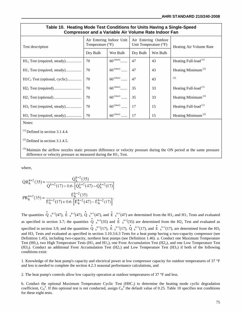
AHRI STANDARD 210/240-2008
75
Table 10. Heating Mode Test Conditions for Units Having a Single-SpeedCompressor and a Variable Air Volume Rate Indoor Fan
Test description
Air Entering Indoor UnitTemperature (°F)
Air Entering OutdoorUnit Temperature (°F)
Heating Air Volume Rate
Dry Bulb Wet Bulb Dry Bulb Wet Bulb
H12 Test (required, steady)................
H11 Test (required, steady)................
H1C1 Test (optional, cyclic)..............
H22 Test (required)............................
H21 Test (optional)............................
H32 Test (required, steady)................
H31 Test (required, steady)................
70
70
70
70
70
70
70
60 (max).......
60 (max) ......
60 (max) ......
60 (max).......
60 (max) ......
60 (max) ......
60 (max) ......
47
47
47
35
35
17
17
43
43
43
33
33
15
15
Heating Full-load (1)
Heating Minimum (2)
(3)
Heating Full-load (1)
Heating Minimum (2)
Heating Full-load (1)
Heating Minimum (2)
Notes:
(1) Defined in section 3.1.4.4.
(2) Defined in section 3.1.4.5.
(3) Maintain the airflow nozzles static pressure difference or velocity pressure during the ON period at the same pressuredifference or velocity pressure as measured during the H11 Test.
where,
The quantities Q
hk=2(47), E
hk=2(47), Q
hk=1(47), and E
hk=1(47) are determined from the H12 and H11 Tests and evaluated
as specified in section 3.7; the quantities Q
hk=2(35) and E
hk=2(35) are determined from the H22 Test and evaluated as
specified in section 3.9; and the quantities Q
hk=2(17), E
hk=2(17), Q
hk=1(17), and E
hk=1(17), are determined from the H32
and H31 Tests and evaluated as specified in section 3.10.3.6.3 Tests for a heat pump having a two-capacity compressor (seeDefinition 1.45), including two-capacity, northern heat pumps (see Definition 1.46). a. Conduct one Maximum TemperatureTest (H01), two High Temperature Tests (H12 and H11), one Frost Accumulation Test (H22), and one Low Temperature Test(H32). Conduct an additional Frost Accumulation Test (H21) and Low Temperature Test (H31) if both of the followingconditions exist:
1. Knowledge of the heat pump's capacity and electrical power at low compressor capacity for outdoor temperatures of 37 °Fand less is needed to complete the section 4.2.3 seasonal performance calculations, and
2. The heat pump's controls allow low capacity operation at outdoor temperatures of 37 °F and less.
b. Conduct the optional Maximum Temperature Cyclic Test (H0C1) to determine the heating mode cyclic degradationcoefficient, CD
h. If this optional test is not conducted, assign CDh the default value of 0.25. Table 10 specifies test conditions
for these eight tests.
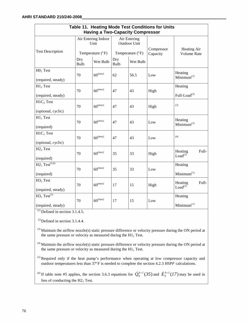
AHRI STANDARD 210/240-2008
76
Table 11. Heating Mode Test Conditions for UnitsHaving a Two-Capacity Compressor
Test Description
Air Entering IndoorUnit
Temperature (F)
Air EnteringOutdoor Unit
Temperature (F)CompressorCapacity
Heating AirVolume Rate
DryBulb
Wet BulbDryBulb
Wet Bulb
H01 Test
(required, steady)70 60(max) 62 56.5 Low
HeatingMinimum(1)
H12 Test
(required, steady)70 60(max) 47 43 High
Heating
Full-Load(2)
H1C2 Test
(optional, cyclic)70 60(max) 47 43 High (3)
H11 Test
(required)70 60(max) 47 43 Low
HeatingMinimum(1)
H1C1 Test
(optional, cyclic)70 60(max) 47 43 Low (4)
H22 Test
(required)70 60(max) 35 33 High
Heating Full-Load(2)
H21 Test(5,6)
(required)70 60(max) 35 33 Low
Heating
Minimum(1)
H32 Test
(required, steady)70 60(max) 17 15 High
Heating Full-Load(2)
H31 Test(5)
(required, steady)70 60(max) 17 15 Low
Heating
Minimum(1)
(1) Defined in section 3.1.4.5.
(2)Defined in section 3.1.4.4.
(3) Maintain the airflow nozzle(s) static pressure difference or velocity pressure during the ON period atthe same pressure or velocity as measured during the H12 Test.
(4) Maintain the airflow nozzle(s) static pressure difference or velocity pressure during the ON period atthe same pressure or velocity as measured during the H11 Test.
(5) Required only if the heat pump’s performance when operating at low compressor capacity andoutdoor temperatures less than 37F is needed to complete the section 4.2.3 HSPF calculations.
(6) If table note #5 applies, the section 3.6.3 equations for )(35Q 1kh and )(17E 1k
h may be used in
lieu of conducting the H21 Test.
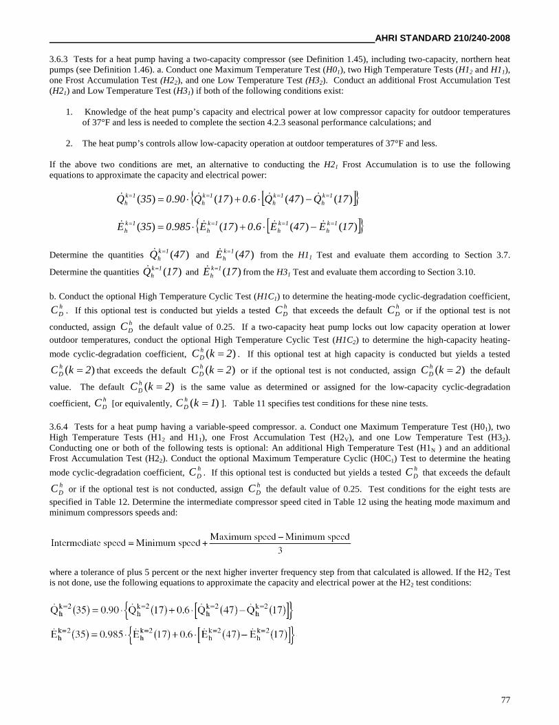
AHRI STANDARD 210/240-2008
77
3.6.3 Tests for a heat pump having a two-capacity compressor (see Definition 1.45), including two-capacity, northern heatpumps (see Definition 1.46). a. Conduct one Maximum Temperature Test (H01), two High Temperature Tests (H12 and H11),one Frost Accumulation Test (H22), and one Low Temperature Test (H32). Conduct an additional Frost Accumulation Test(H21) and Low Temperature Test (H31) if both of the following conditions exist:
1. Knowledge of the heat pump’s capacity and electrical power at low compressor capacity for outdoor temperaturesof 37°F and less is needed to complete the section 4.2.3 seasonal performance calculations; and
2. The heat pump’s controls allow low-capacity operation at outdoor temperatures of 37°F and less.
If the above two conditions are met, an alternative to conducting the H21 Frost Accumulation is to use the followingequations to approximate the capacity and electrical power:
)()(.)(.)( 17Q47Q6017Q90035Q 1kh
1kh
1kh
1kh
)()(.)(.)( 17E47E6017E985035E 1kh
1kh
1kh
1kh
Determine the quantities )(47Q 1kh and )(47E 1k
h from the H11 Test and evaluate them according to Section 3.7.
Determine the quantities )(17Q 1kh and )(17E 1k
h from the H31 Test and evaluate them according to Section 3.10.
b. Conduct the optional High Temperature Cyclic Test (H1C1) to determine the heating-mode cyclic-degradation coefficient,hDC . If this optional test is conducted but yields a tested
hDC that exceeds the default
hDC or if the optional test is not
conducted, assignhDC the default value of 0.25. If a two-capacity heat pump locks out low capacity operation at lower
outdoor temperatures, conduct the optional High Temperature Cyclic Test (H1C2) to determine the high-capacity heating-
mode cyclic-degradation coefficient, )( 2kC hD . If this optional test at high capacity is conducted but yields a tested
)( 2kC hD that exceeds the default )( 2kC h
D or if the optional test is not conducted, assign )( 2kC hD the default
value. The default )( 2kC hD is the same value as determined or assigned for the low-capacity cyclic-degradation
coefficient,hDC [or equivalently, )( 1kC h
D ]. Table 11 specifies test conditions for these nine tests.
3.6.4 Tests for a heat pump having a variable-speed compressor. a. Conduct one Maximum Temperature Test (H01), twoHigh Temperature Tests (H12 and H11), one Frost Accumulation Test (H2V), and one Low Temperature Test (H32).Conducting one or both of the following tests is optional: An additional High Temperature Test (H1N ) and an additionalFrost Accumulation Test (H22). Conduct the optional Maximum Temperature Cyclic (H0C1) Test to determine the heating
mode cyclic-degradation coefficient,hDC . If this optional test is conducted but yields a tested
hDC that exceeds the default
hDC or if the optional test is not conducted, assign
hDC the default value of 0.25. Test conditions for the eight tests are
specified in Table 12. Determine the intermediate compressor speed cited in Table 12 using the heating mode maximum andminimum compressors speeds and:
where a tolerance of plus 5 percent or the next higher inverter frequency step from that calculated is allowed. If the H22 Testis not done, use the following equations to approximate the capacity and electrical power at the H22 test conditions:
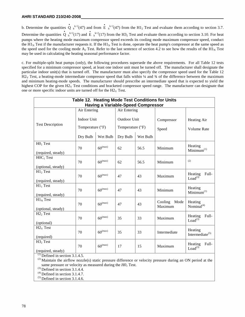
AHRI STANDARD 210/240-2008
78
b. Determine the quantities Q
hk=2(47) and from E
hk=2(47) from the H12 Test and evaluate them according to section 3.7.
Determine the quantities Q
hk=2(17) and E
hk=2(17) from the H32 Test and evaluate them according to section 3.10. For heat
pumps where the heating mode maximum compressor speed exceeds its cooling mode maximum compressor speed, conductthe H1N Test if the manufacturer requests it. If the H1N Test is done, operate the heat pump's compressor at the same speed asthe speed used for the cooling mode A2 Test. Refer to the last sentence of section 4.2 to see how the results of the H1N Testmay be used in calculating the heating seasonal performance factor.
c. For multiple-split heat pumps (only), the following procedures supersede the above requirements. For all Table 12 testsspecified for a minimum compressor speed, at least one indoor unit must be turned off. The manufacturer shall designate theparticular indoor unit(s) that is turned off. The manufacturer must also specify the compressor speed used for the Table 12H2V Test, a heating-mode intermediate compressor speed that falls within ¼ and ¾ of the difference between the maximumand minimum heating-mode speeds. The manufacturer should prescribe an intermediate speed that is expected to yield thehighest COP for the given H2V Test conditions and bracketed compressor speed range. The manufacturer can designate thatone or more specific indoor units are turned off for the H2V Test.
Table 12. Heating Mode Test Conditions for UnitsHaving a Variable-Speed Compressor
Test Description
Air Entering
Indoor Unit
Air Entering
Outdoor Unit Compressor
Speed
Heating Air
Volume RateTemperature (F) Temperature (F)
Dry Bulb Wet Bulb Dry Bulb Wet Bulb
H01 Test
(required, steady)70 60(max) 62 56.5 Minimum
HeatingMinimum(1)
H0C1 Test
(optional, steady)70 60(max) 62 56.5 Minimum (2)
H12 Test
(required, steady)70 60(max) 47 43 Maximum
Heating Full-Load(3)
H11 Test
(required, steady)70 60(max) 47 43 Minimum
HeatingMinimum(1)
H1N Test
(optional, steady)70 60(max) 47 43
Cooling ModeMaximum
HeatingNominal(4)
H22 Test
(optional)70 60(max) 35 33 Maximum
Heating Full-Load(3)
H2V Test
(required)70 60(max) 35 33 Intermediate
HeatingIntermediate(5)
H32 Test
(required, steady)70 60(max) 17 15 Maximum
Heating Full-Load(3)
(1) Defined in section 3.1.4.5.(2) Maintain the airflow nozzle(s) static pressure difference or velocity pressure during an ON period at the
same pressure or velocity as measured during the H01 Test.(3) Defined in section 3.1.4.4.(4) Defined in section 3.1.4.7.(5) Defined in section 3.1.4.6.
AHRI STANDARD 210/240-2008
79
3.6.5 Additional test for a heat pump having a heat comfort controller. Test any heat pump that has a heat comfort controller(see Definition 1.28) according to section 3.6.1, 3.6.2, or 3.6.3, whichever applies, with the heat comfort controller disabled.Additionally, conduct the abbreviated test described in section 3.1.9 with the heat comfort controller active to determine thesystem's maximum supply air temperature. (Note: heat pumps having a variable speed compressor and a heat comfortcontroller are not covered in the test procedure at this time.)
3.7 Test procedures for steady-state Maximum Temperature and High Temperature heating mode tests (the H01, H1, H12,H11, and H1N Tests). a. For the pretest interval, operate the test room reconditioning apparatus and the heat pump untilequilibrium conditions are maintained for at least 30 minutes at the specified section 3.6 test conditions. Use the exhaust fanof the airflow measuring apparatus and, if installed, the indoor fan of the heat pump to obtain and then maintain the indoor airvolume rate and/or the external static pressure specified for the particular test. Continuously record the dry-bulb temperatureof the air entering the indoor coil, and the dry-bulb temperature and water vapor content of the air entering the outdoor coil.Refer to section 3.11 for additional requirements that depend on the selected secondary test method. After satisfying thepretest equilibrium requirements, make the measurements specified in Table 3 of ASHRAE Standard 37–2005 (incorporatedby reference, see §430.22) for the Indoor Air Enthalpy method and the user-selected secondary method. Except for externalstatic pressure, make the Table 3 measurements at equal intervals that span 10 minutes or less. Measure external staticpressure every 5 minutes or less. Continue data sampling until a 30-minute period (e.g., four consecutive 10-minute samples)is reached where the test tolerances specified in Table 13 are satisfied. For those continuously recorded parameters, use theentire data set for the 30-minute interval when evaluating Table 13 compliance. Determine the average electrical powerconsumption of the heat pump over the same 30-minute interval.
b. Calculate indoor-side total heating capacity as specified in sections 7.3.4.1 and 7.3.4.3 of ASHRAE Standard 37-2005(incorporated by reference, see §430.22). Do not adjust the parameters used in calculating capacity for the permittedvariations in test conditions. Assign the average space heating capacity and electrical power over the 30-minute data
collection interval to the variables Q
hk and E
hk(T) respectively. The “T” and superscripted “k” are the same as described in
section 3.3. Additionally, for the heating mode, use the superscript to denote results from the optional H1N Test, if conducted.
c. For heat pumps tested without an indoor fan installed, increase Q
hk(T) by
and increase E
hk(T) by,
where V
s is the average measured indoor air volume rate expressed in units of cubic feet per minute of standard air (scfm).During the 30-minute data collection interval of a High Temperature Test, pay attention to preventing a defrost cycle. Prior tothis time, allow the heat pump to perform a defrost cycle if automatically initiated by its own controls. As in all cases, waitfor the heat pump's defrost controls to automatically terminate the defrost cycle. Heat pumps that undergo a defrost shouldoperate in the heating mode for at least 10 minutes after defrost termination prior to beginning the 30-minute data collectioninterval. For some heat pumps, frost may accumulate on the outdoor coil during a High Temperature test. If the indoor coilleaving air temperature or the difference between the leaving and entering air temperatures decreases by more than 1.5 °Fover the 30-minute data collection interval, then do not use the collected data to determine capacity. Instead, initiate a defrostcycle. Begin collecting data no sooner than 10 minutes after defrost termination. Collect 30 minutes of new data duringwhich the Table 13 test tolerances are satisfied. In this case, use only the results from the second 30-minute data collection
interval to evaluate Q
hk(47) and E
hk(47).
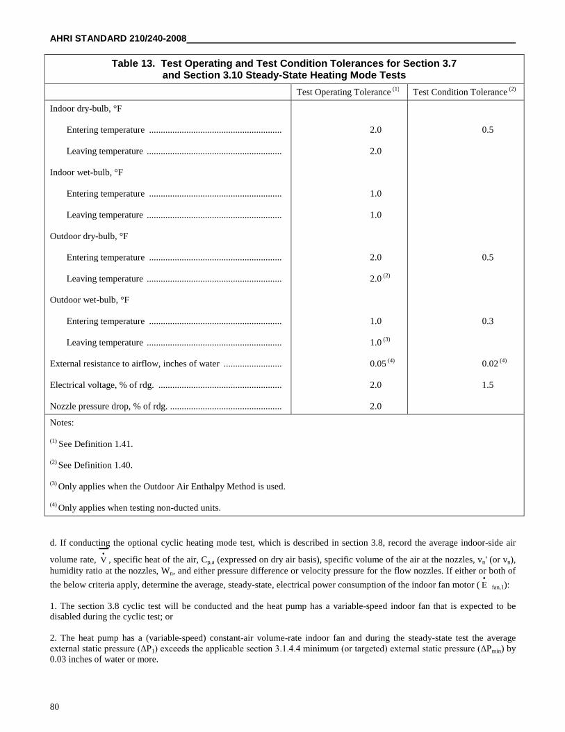
AHRI STANDARD 210/240-2008
80
Table 13. Test Operating and Test Condition Tolerances for Section 3.7and Section 3.10 Steady-State Heating Mode Tests
Test Operating Tolerance (1) Test Condition Tolerance (2)
Indoor dry-bulb, °F
Entering temperature .........................................................
Leaving temperature ..........................................................
Indoor wet-bulb, °F
Entering temperature .........................................................
Leaving temperature ..........................................................
Outdoor dry-bulb, °F
Entering temperature .........................................................
Leaving temperature ..........................................................
Outdoor wet-bulb, °F
Entering temperature .........................................................
Leaving temperature ..........................................................
External resistance to airflow, inches of water .........................
Electrical voltage, % of rdg. .....................................................
Nozzle pressure drop, % of rdg. ................................................
2.0
2.0
1.0
1.0
2.0
2.0 (2)
1.0
1.0 (3)
0.05 (4)
2.0
2.0
0.5
0.5
0.3
0.02 (4)
1.5
Notes:
(1) See Definition 1.41.
(2) See Definition 1.40.
(3) Only applies when the Outdoor Air Enthalpy Method is used.
(4) Only applies when testing non-ducted units.
d. If conducting the optional cyclic heating mode test, which is described in section 3.8, record the average indoor-side air
volume rate, V
, specific heat of the air, Cp,a (expressed on dry air basis), specific volume of the air at the nozzles, vn' (or vn),humidity ratio at the nozzles, Wn, and either pressure difference or velocity pressure for the flow nozzles. If either or both of
the below criteria apply, determine the average, steady-state, electrical power consumption of the indoor fan motor ( E
fan,1):
1. The section 3.8 cyclic test will be conducted and the heat pump has a variable-speed indoor fan that is expected to bedisabled during the cyclic test; or
2. The heat pump has a (variable-speed) constant-air volume-rate indoor fan and during the steady-state test the averageexternal static pressure (ΔP1) exceeds the applicable section 3.1.4.4 minimum (or targeted) external static pressure (ΔPmin) by0.03 inches of water or more.
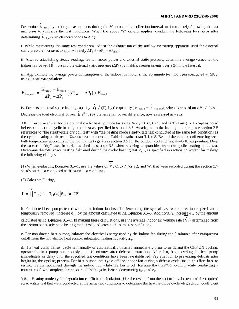
AHRI STANDARD 210/240-2008
81
Determine E
fan,1 by making measurements during the 30-minute data collection interval, or immediately following the testand prior to changing the test conditions. When the above “2” criteria applies, conduct the following four steps after
determining E
fan,1 (which corresponds to ΔP1):
i. While maintaining the same test conditions, adjust the exhaust fan of the airflow measuring apparatus until the externalstatic pressure increases to approximately ΔP1 + (ΔP1 − ΔPmin).
ii. After re-establishing steady readings for fan motor power and external static pressure, determine average values for the
indoor fan power ( E
fan,2) and the external static pressure (ΔP2) by making measurements over a 5-minute interval.
iii. Approximate the average power consumption of the indoor fan motor if the 30-minute test had been conducted at ΔPmin
using linear extrapolation:
iv. Decrease the total space heating capacity, Q
hk (T), by the quantity ( E
fan, 1 − E
fan, min), when expressed on a Btu/h basis.
Decrease the total electrical power, E
hk (T) by the same fan power difference, now expressed in watts.
3.8 Test procedures for the optional cyclic heating mode tests (the H0C1, H1C, H1C1 and H1C2 Tests). a. Except as notedbelow, conduct the cyclic heating mode test as specified in section 3.5. As adapted to the heating mode, replace section 3.5references to “the steady-state dry coil test” with “the heating mode steady-state test conducted at the same test conditions asthe cyclic heating mode test.” Use the test tolerances in Table 14 rather than Table 8. Record the outdoor coil entering wet-bulb temperature according to the requirements given in section 3.5 for the outdoor coil entering dry-bulb temperature. Dropthe subscript “dry” used in variables cited in section 3.5 when referring to quantities from the cyclic heating mode test.Determine the total space heating delivered during the cyclic heating test, qcyc, as specified in section 3.5 except for makingthe following changes:
(1) When evaluating Equation 3.5–1, use the values of V
, Cp,a,vn', (or vn), and Wn that were recorded during the section 3.7steady-state test conducted at the same test conditions.
(2) Calculate Γ using,
b. For ducted heat pumps tested without an indoor fan installed (excluding the special case where a variable-speed fan istemporarily removed), increase qcyc by the amount calculated using Equation 3.5–3. Additionally, increase ecyc by the amount
calculated using Equation 3.5–2. In making these calculations, use the average indoor air volume rate ( V
s) determined fromthe section 3.7 steady-state heating mode test conducted at the same test conditions.
c. For non-ducted heat pumps, subtract the electrical energy used by the indoor fan during the 3 minutes after compressorcutoff from the non-ducted heat pump's integrated heating capacity, qcyc.
d. If a heat pump defrost cycle is manually or automatically initiated immediately prior to or during the OFF/ON cycling,operate the heat pump continuously until 10 minutes after defrost termination. After that, begin cycling the heat pumpimmediately or delay until the specified test conditions have been re-established. Pay attention to preventing defrosts afterbeginning the cycling process. For heat pumps that cycle off the indoor fan during a defrost cycle, make no effort here torestrict the air movement through the indoor coil while the fan is off. Resume the OFF/ON cycling while conducting aminimum of two complete compressor OFF/ON cycles before determining qcyc and ecyc.
3.8.1 Heating mode cyclic-degradation coefficient calculation. Use the results from the optional cyclic test and the requiredsteady-state test that were conducted at the same test conditions to determine the heating-mode cyclic-degradation coefficient
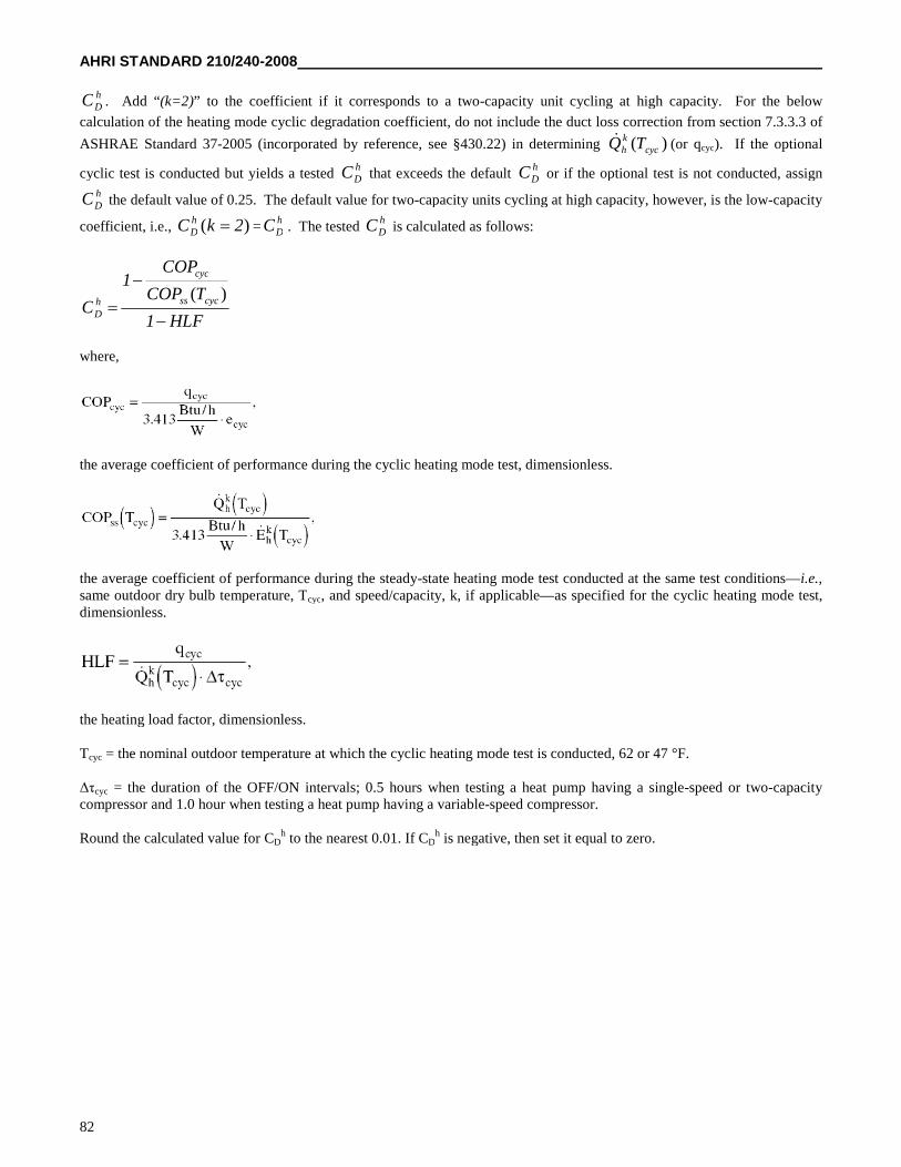
AHRI STANDARD 210/240-2008
82
hDC . Add “(k=2)” to the coefficient if it corresponds to a two-capacity unit cycling at high capacity. For the below
calculation of the heating mode cyclic degradation coefficient, do not include the duct loss correction from section 7.3.3.3 of
ASHRAE Standard 37-2005 (incorporated by reference, see §430.22) in determining )( cyckh TQ (or qcyc). If the optional
cyclic test is conducted but yields a testedhDC that exceeds the default
hDC or if the optional test is not conducted, assign
hDC the default value of 0.25. The default value for two-capacity units cycling at high capacity, however, is the low-capacity
coefficient, i.e., )( 2kC hD =
hDC . The tested
hDC is calculated as follows:
HLF1
TCOP
COP1
Ccycss
cyc
hD
)(
where,
the average coefficient of performance during the cyclic heating mode test, dimensionless.
the average coefficient of performance during the steady-state heating mode test conducted at the same test conditions—i.e.,same outdoor dry bulb temperature, Tcyc, and speed/capacity, k, if applicable—as specified for the cyclic heating mode test,dimensionless.
the heating load factor, dimensionless.
Tcyc = the nominal outdoor temperature at which the cyclic heating mode test is conducted, 62 or 47 °F.
Δτcyc = the duration of the OFF/ON intervals; 0.5 hours when testing a heat pump having a single-speed or two-capacitycompressor and 1.0 hour when testing a heat pump having a variable-speed compressor.
Round the calculated value for CDh to the nearest 0.01. If CD
h is negative, then set it equal to zero.
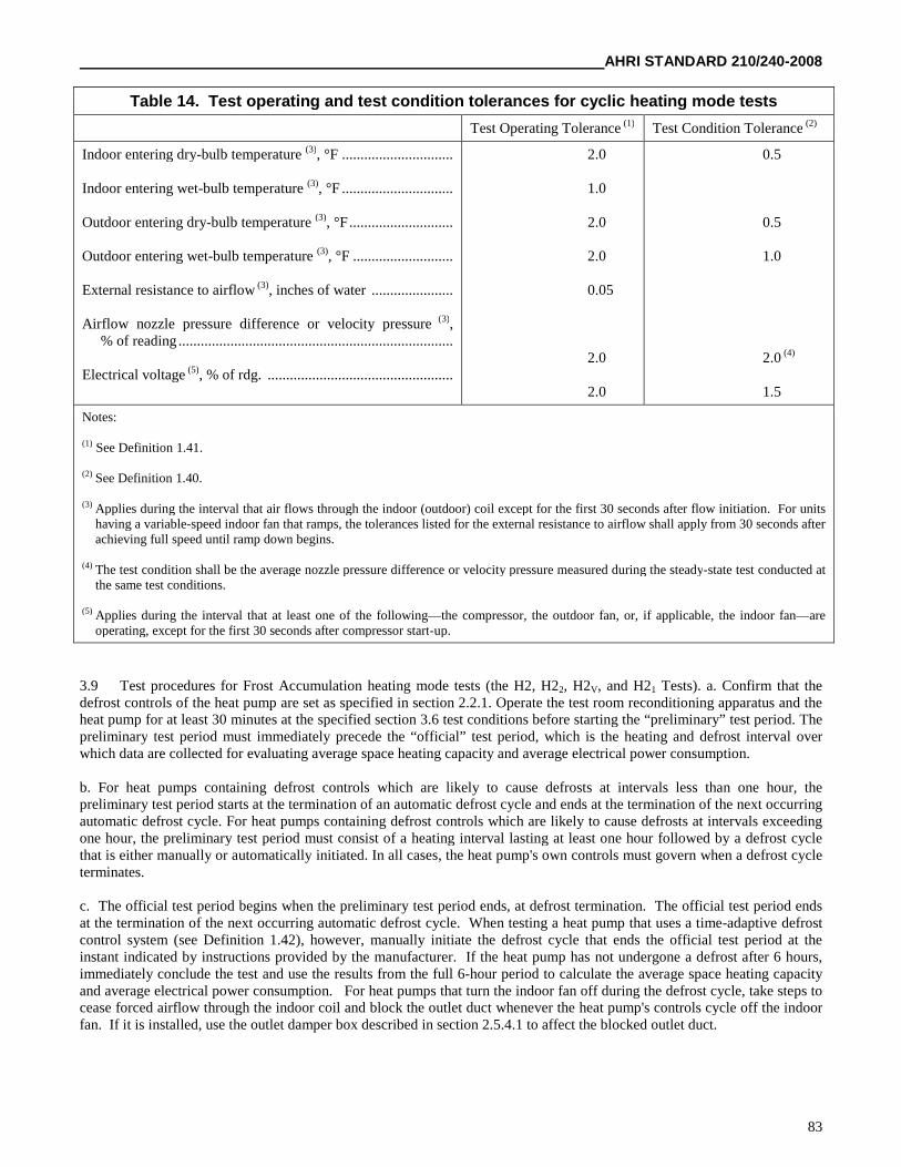
AHRI STANDARD 210/240-2008
83
Table 14. Test operating and test condition tolerances for cyclic heating mode tests
Test Operating Tolerance (1) Test Condition Tolerance (2)
Indoor entering dry-bulb temperature (3), °F ..............................
Indoor entering wet-bulb temperature (3), °F ..............................
Outdoor entering dry-bulb temperature (3), °F............................
Outdoor entering wet-bulb temperature (3), °F ...........................
External resistance to airflow (3), inches of water ......................
Airflow nozzle pressure difference or velocity pressure (3),% of reading ..........................................................................
Electrical voltage (5), % of rdg. ..................................................
2.0
1.0
2.0
2.0
0.05
2.0
2.0
0.5
0.5
1.0
2.0 (4)
1.5
Notes:
(1) See Definition 1.41.
(2) See Definition 1.40.
(3) Applies during the interval that air flows through the indoor (outdoor) coil except for the first 30 seconds after flow initiation. For unitshaving a variable-speed indoor fan that ramps, the tolerances listed for the external resistance to airflow shall apply from 30 seconds afterachieving full speed until ramp down begins.
(4) The test condition shall be the average nozzle pressure difference or velocity pressure measured during the steady-state test conducted atthe same test conditions.
(5) Applies during the interval that at least one of the following—the compressor, the outdoor fan, or, if applicable, the indoor fan—areoperating, except for the first 30 seconds after compressor start-up.
3.9 Test procedures for Frost Accumulation heating mode tests (the H2, H22, H2V, and H21 Tests). a. Confirm that thedefrost controls of the heat pump are set as specified in section 2.2.1. Operate the test room reconditioning apparatus and theheat pump for at least 30 minutes at the specified section 3.6 test conditions before starting the “preliminary” test period. Thepreliminary test period must immediately precede the “official” test period, which is the heating and defrost interval overwhich data are collected for evaluating average space heating capacity and average electrical power consumption.
b. For heat pumps containing defrost controls which are likely to cause defrosts at intervals less than one hour, thepreliminary test period starts at the termination of an automatic defrost cycle and ends at the termination of the next occurringautomatic defrost cycle. For heat pumps containing defrost controls which are likely to cause defrosts at intervals exceedingone hour, the preliminary test period must consist of a heating interval lasting at least one hour followed by a defrost cyclethat is either manually or automatically initiated. In all cases, the heat pump's own controls must govern when a defrost cycleterminates.
c. The official test period begins when the preliminary test period ends, at defrost termination. The official test period endsat the termination of the next occurring automatic defrost cycle. When testing a heat pump that uses a time-adaptive defrostcontrol system (see Definition 1.42), however, manually initiate the defrost cycle that ends the official test period at theinstant indicated by instructions provided by the manufacturer. If the heat pump has not undergone a defrost after 6 hours,immediately conclude the test and use the results from the full 6-hour period to calculate the average space heating capacityand average electrical power consumption. For heat pumps that turn the indoor fan off during the defrost cycle, take steps tocease forced airflow through the indoor coil and block the outlet duct whenever the heat pump's controls cycle off the indoorfan. If it is installed, use the outlet damper box described in section 2.5.4.1 to affect the blocked outlet duct.
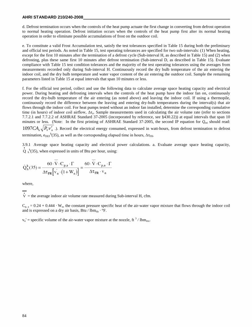
AHRI STANDARD 210/240-2008
84
d. Defrost termination occurs when the controls of the heat pump actuate the first change in converting from defrost operationto normal heating operation. Defrost initiation occurs when the controls of the heat pump first alter its normal heatingoperation in order to eliminate possible accumulations of frost on the outdoor coil.
e. To constitute a valid Frost Accumulation test, satisfy the test tolerances specified in Table 15 during both the preliminaryand official test periods. As noted in Table 15, test operating tolerances are specified for two sub-intervals: (1) When heating,except for the first 10 minutes after the termination of a defrost cycle (Sub-interval H, as described in Table 15) and (2) whendefrosting, plus these same first 10 minutes after defrost termination (Sub-interval D, as described in Table 15). Evaluatecompliance with Table 15 test condition tolerances and the majority of the test operating tolerances using the averages frommeasurements recorded only during Sub-interval H. Continuously record the dry bulb temperature of the air entering theindoor coil, and the dry bulb temperature and water vapor content of the air entering the outdoor coil. Sample the remainingparameters listed in Table 15 at equal intervals that span 10 minutes or less.
f. For the official test period, collect and use the following data to calculate average space heating capacity and electricalpower. During heating and defrosting intervals when the controls of the heat pump have the indoor fan on, continuouslyrecord the dry-bulb temperature of the air entering (as noted above) and leaving the indoor coil. If using a thermopile,continuously record the difference between the leaving and entering dry-bulb temperatures during the interval(s) that airflows through the indoor coil. For heat pumps tested without an indoor fan installed, determine the corresponding cumulativetime (in hours) of indoor coil airflow, Δτa. Sample measurements used in calculating the air volume rate (refer to sections7.7.2.1 and 7.7.2.2 of ASHRAE Standard 37-2005 (incorporated by reference, see §430.22)) at equal intervals that span 10minutes or less. (Note: In the first printing of ASHRAE Standard 37-2005, the second IP equation for Qmi should read:
nVn PCA 1097 .). Record the electrical energy consumed, expressed in watt-hours, from defrost termination to defrost
termination, eDEFk(35), as well as the corresponding elapsed time in hours, ΔτFR.
3.9.1 Average space heating capacity and electrical power calculations. a. Evaluate average space heating capacity,
Q
hk(35), when expressed in units of Btu per hour, using:
where,
V
= the average indoor air volume rate measured during Sub-interval H, cfm.
Cp, a = 0.24 + 0.444 · Wn, the constant pressure specific heat of the air-water vapor mixture that flows through the indoor coiland is expressed on a dry air basis, Btu / lbmda · °F.
vn' = specific volume of the air-water vapor mixture at the nozzle, ft 3 / lbmmx.
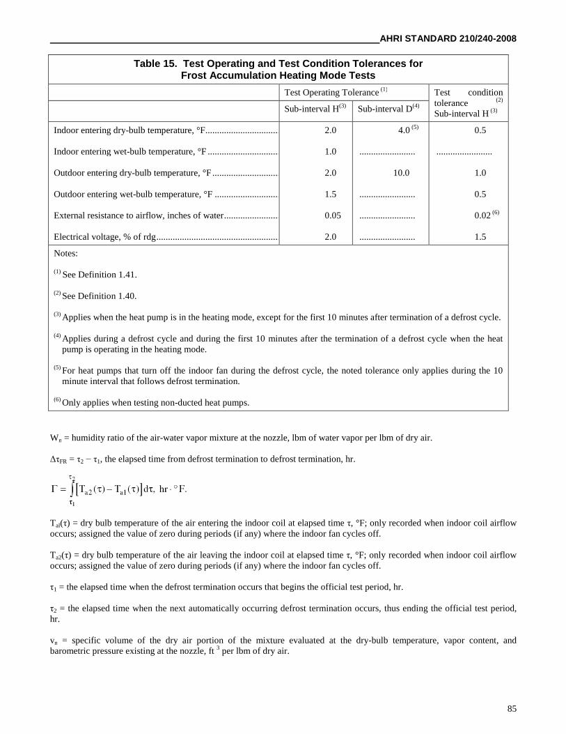
AHRI STANDARD 210/240-2008
85
Wn = humidity ratio of the air-water vapor mixture at the nozzle, lbm of water vapor per lbm of dry air.
ΔτFR = τ2 − τ1, the elapsed time from defrost termination to defrost termination, hr.
Tal(τ) = dry bulb temperature of the air entering the indoor coil at elapsed time τ, °F; only recorded when indoor coil airflowoccurs; assigned the value of zero during periods (if any) where the indoor fan cycles off.
Ta2(τ) = dry bulb temperature of the air leaving the indoor coil at elapsed time τ, °F; only recorded when indoor coil airflowoccurs; assigned the value of zero during periods (if any) where the indoor fan cycles off.
τ1 = the elapsed time when the defrost termination occurs that begins the official test period, hr.
τ2 = the elapsed time when the next automatically occurring defrost termination occurs, thus ending the official test period,hr.
vn = specific volume of the dry air portion of the mixture evaluated at the dry-bulb temperature, vapor content, andbarometric pressure existing at the nozzle, ft 3 per lbm of dry air.
Table 15. Test Operating and Test Condition Tolerances forFrost Accumulation Heating Mode Tests
Test Operating Tolerance (1) Test conditiontolerance (2)
Sub-interval H (3)Sub-interval H(3) Sub-interval D(4)
Indoor entering dry-bulb temperature, °F................................
Indoor entering wet-bulb temperature, °F ................................
Outdoor entering dry-bulb temperature, °F ................................
Outdoor entering wet-bulb temperature, °F ................................
External resistance to airflow, inches of water................................
Electrical voltage, % of rdg..............................................................
2.0
1.0
2.0
1.5
0.05
2.0
4.0 (5)
........................
10.0
........................
........................
........................
0.5
........................
1.0
0.5
0.02 (6)
1.5
Notes:
(1) See Definition 1.41.
(2) See Definition 1.40.
(3) Applies when the heat pump is in the heating mode, except for the first 10 minutes after termination of a defrost cycle.
(4) Applies during a defrost cycle and during the first 10 minutes after the termination of a defrost cycle when the heatpump is operating in the heating mode.
(5) For heat pumps that turn off the indoor fan during the defrost cycle, the noted tolerance only applies during the 10minute interval that follows defrost termination.
(6) Only applies when testing non-ducted heat pumps.
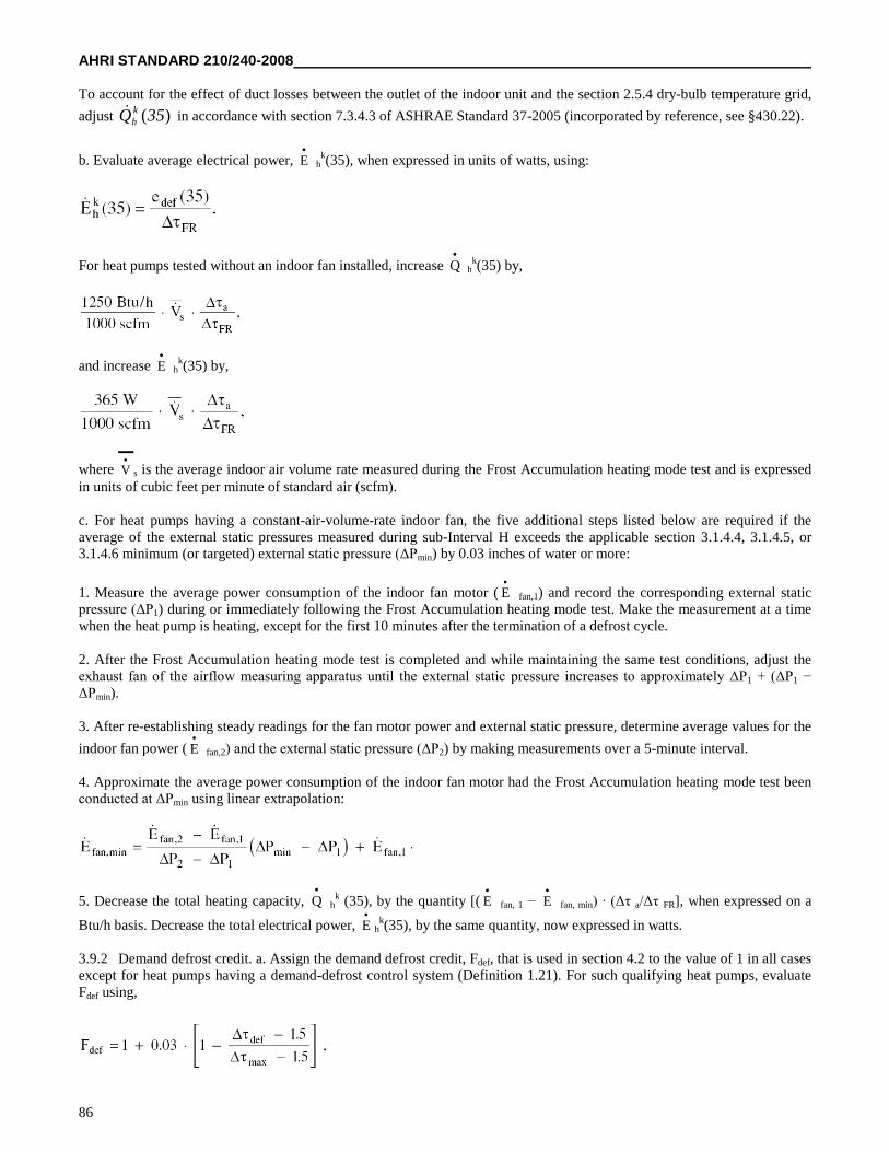
AHRI STANDARD 210/240-2008
86
To account for the effect of duct losses between the outlet of the indoor unit and the section 2.5.4 dry-bulb temperature grid,
adjust )(35Q kh in accordance with section 7.3.4.3 of ASHRAE Standard 37-2005 (incorporated by reference, see §430.22).
b. Evaluate average electrical power, E
hk(35), when expressed in units of watts, using:
For heat pumps tested without an indoor fan installed, increase Q
hk(35) by,
and increase E
hk(35) by,
where V
s is the average indoor air volume rate measured during the Frost Accumulation heating mode test and is expressedin units of cubic feet per minute of standard air (scfm).
c. For heat pumps having a constant-air-volume-rate indoor fan, the five additional steps listed below are required if theaverage of the external static pressures measured during sub-Interval H exceeds the applicable section 3.1.4.4, 3.1.4.5, or3.1.4.6 minimum (or targeted) external static pressure (ΔPmin) by 0.03 inches of water or more:
1. Measure the average power consumption of the indoor fan motor ( E
fan,1) and record the corresponding external staticpressure (ΔP1) during or immediately following the Frost Accumulation heating mode test. Make the measurement at a timewhen the heat pump is heating, except for the first 10 minutes after the termination of a defrost cycle.
2. After the Frost Accumulation heating mode test is completed and while maintaining the same test conditions, adjust theexhaust fan of the airflow measuring apparatus until the external static pressure increases to approximately ΔP1 + (ΔP1 −ΔPmin).
3. After re-establishing steady readings for the fan motor power and external static pressure, determine average values for the
indoor fan power ( E
fan,2) and the external static pressure (ΔP2) by making measurements over a 5-minute interval.
4. Approximate the average power consumption of the indoor fan motor had the Frost Accumulation heating mode test beenconducted at ΔPmin using linear extrapolation:
5. Decrease the total heating capacity, Q
hk (35), by the quantity [( E
fan, 1 − E
fan, min) · (Δτ a/Δτ FR], when expressed on a
Btu/h basis. Decrease the total electrical power, E
hk(35), by the same quantity, now expressed in watts.
3.9.2 Demand defrost credit. a. Assign the demand defrost credit, Fdef, that is used in section 4.2 to the value of 1 in all casesexcept for heat pumps having a demand-defrost control system (Definition 1.21). For such qualifying heat pumps, evaluateFdef using,
AHRI STANDARD 210/240-2008
87
where,
Δτdef = the time between defrost terminations (in hours) or 1.5, whichever is greater.
Δτmax = maximum time between defrosts as allowed by the controls (in hours) or 12, whichever is less.
b. For two-capacity heat pumps and for section 3.6.2 units, evaluate the above equation using the Δτdef that applies based onthe Frost Accumulation Test conducted at high capacity and/or at the Heating Full-load Air Volume Rate. For variable-speedheat pumps, evaluate Δτdef based on the required Frost Accumulation Test conducted at the intermediate compressor speed.
3.10 Test procedures for steady-state Low Temperature heating mode tests (the H3, H32, and H31 Tests). Except for themodifications noted in this section, conduct the Low Temperature heating mode test using the same approach as specified insection 3.7 for the Maximum and High Temperature tests. After satisfying the section 3.7 requirements for the pretest interval
but before beginning to collect data to determine Q
hk (17) and E
hk (17), conduct a defrost cycle. This defrost cycle may be
manually or automatically initiated. The defrost sequence must be terminated by the action of the heat pump's defrost
controls. Begin the 30-minute data collection interval described in section 3.7, from which Q
hk (17) and E
hk (17) are
determined, no sooner than 10 minutes after defrost termination. Defrosts should be prevented over the 30-minute datacollection interval.
3.11 Additional requirements for the secondary test methods.
3.11.1 If using the Outdoor Air Enthalpy Method as the secondary test method. During the “official” test, the outdoor air-side test apparatus described in section 2.10.1 is connected to the outdoor unit. To help compensate for any effect that theaddition of this test apparatus may have on the unit's performance, conduct a “preliminary” test where the outdoor air-sidetest apparatus is disconnected. Conduct a preliminary test prior to the first section 3.2 steady-state cooling mode test and priorto the first section 3.6 steady-state heating mode test. No other preliminary tests are required so long as the unit operates theoutdoor fan during all cooling mode steady-state tests at the same speed and all heating mode steady-state tests at the samespeed. If using more than one outdoor fan speed for the cooling mode steady-state tests, however, conduct a preliminary testprior to each cooling mode test where a different fan speed is first used. This same requirement applies for the heating modetests.
3.11.1.1 If a preliminary test precedes the official test. a. The test conditions for the preliminary test are the same as specifiedfor the official test. Connect the indoor air-side test apparatus to the indoor coil; disconnect the outdoor air-side testapparatus. Allow the test room reconditioning apparatus and the unit being tested to operate for at least one hour. Afterattaining equilibrium conditions, measure the following quantities at equal intervals that span 10 minutes or less:
1. The section 2.10.1 evaporator and condenser temperatures or pressures;
2. Parameters required according to the Indoor Air Enthalpy Method.
Continue these measurements until a 30-minute period (e.g., four consecutive 10-minute samples) is obtained where theTable 7 or Table 13, whichever applies, test tolerances are satisfied.
b. After collecting 30 minutes of steady-state data, reconnect the outdoor air-side test apparatus to the unit. Adjust the exhaustfan of the outdoor airflow measuring apparatus until averages for the evaporator and condenser temperatures, or the saturatedtemperatures corresponding to the measured pressures, agree within ±0.5 °F of the averages achieved when the outdoor air-side test apparatus was disconnected. Calculate the averages for the reconnected case using five or more consecutive readingstaken at one minute intervals. Make these consecutive readings after re-establishing equilibrium conditions and beforeinitiating the official test.
3.11.1.2 If a preliminary test does not precede the official test. Connect the outdoor-side test apparatus to the unit. Adjust theexhaust fan of the outdoor airflow measuring apparatus to achieve the same external static pressure as measured during theprior preliminary test conducted with the unit operating in the same cooling or heating mode at the same outdoor fan speed.
AHRI STANDARD 210/240-2008
88
3.11.1.3 Official test. a. Continue (preliminary test was conducted) or begin (no preliminary test) the official test by makingmeasurements for both the Indoor and Outdoor Air Enthalpy Methods at equal intervals that span 10 minutes or less.Discontinue these measurement only after obtaining a 30-minute period where the specified test condition and test operatingtolerances are satisfied. To constitute a valid official test:
(1) Achieve the energy balance specified in section 3.1.1; and,
(2) For cases where a preliminary test is conducted, the capacities determined using the Indoor Air Enthalpy Method from theofficial and preliminary test periods must agree within 2.0 percent.
b. For space cooling tests, calculate capacity from the outdoor air-enthalpy measurements as specified in sections 7.3.3.2 and7.3.3.3 of ASHRAE Standard 37-2005 (incorporated by reference, see §430.22). Calculate heating capacity based on outdoorair-enthalpy measurements as specified in sections 7.3.4.2 and 7.3.3.4.3 of the same ASHRAE Standard. Adjust the outdoor-side capacity according to section 7.3.3.4 of ASHRAE Standard 37-2005 (incorporated by reference, see §430.22) to accountfor line losses when testing split systems. Use the outdoor unit fan power as measured during the official test and not thevalue measured during the preliminary test, as described in section 8.6.2 of ASHRAE Standard 37-2005 (incorporated byreference, see §430.22), when calculating the capacity.
3.11.2 If using the Compressor Calibration Method as the secondary test method.
a. Conduct separate calibration tests using a calorimeter to determine the refrigerant flow rate. Or for cases where thesuperheat of the refrigerant leaving the evaporator is less than 5 °F, use the calorimeter to measure total capacity rather thanrefrigerant flow rate. Conduct these calibration tests at the same test conditions as specified for the tests in this Appendix.Operate the unit for at least one hour or until obtaining equilibrium conditions before collecting data that will be used indetermining the average refrigerant flow rate or total capacity. Sample the data at equal intervals that span 10 minutes or less.Determine average flow rate or average capacity from data sampled over a 30-minute period where the Table 7 (cooling) orthe Table 13 (heating) tolerances are satisfied. Otherwise, conduct the calibration tests according to ASHRAE Standard 23-05(incorporated by reference, see §430.22), ASHRAE Standard 41.9-2000 (incorporated by reference, see §430.22), and section7.4 of ASHRAE Standard 37-2005 (incorporated by reference, see §430.22).
b. Calculate space cooling and space heating capacities using the compressor calibration method measurements as specifiedin section 7.4.5 and 7.4.6 respectively, of ASHRAE Standard 37-2005 (incorporated by reference, see §430.22).
3.11.3 If using the Refrigerant-Enthalpy Method as the secondary test method. Conduct this secondary method accordingto section 7.5 of ASHRAE Standard 37-2005 (incorporated by reference, see §430.22). Calculate space cooling and heatingcapacities using the refrigerant-enthalpy method measurements as specified in sections 7.5.4 and 7.5.5, respectively, of thesame ASHRAE Standard.
3.12 Rounding of space conditioning capacities for reporting purposes.
a. When reporting rated capacities, round them off as follows:
1. For capacities less than 20,000 Btu/h, round to the nearest 100 Btu/h.
2. For capacities between 20,000 and 37,999 Btu/h, round to the nearest 200 Btu/h.
3. For capacities between 38,000 and 64,999 Btu/h, round to the nearest 500 Btu/h.
b. For the capacities used to perform the section 4 calculations, however, round only to the nearest integer.
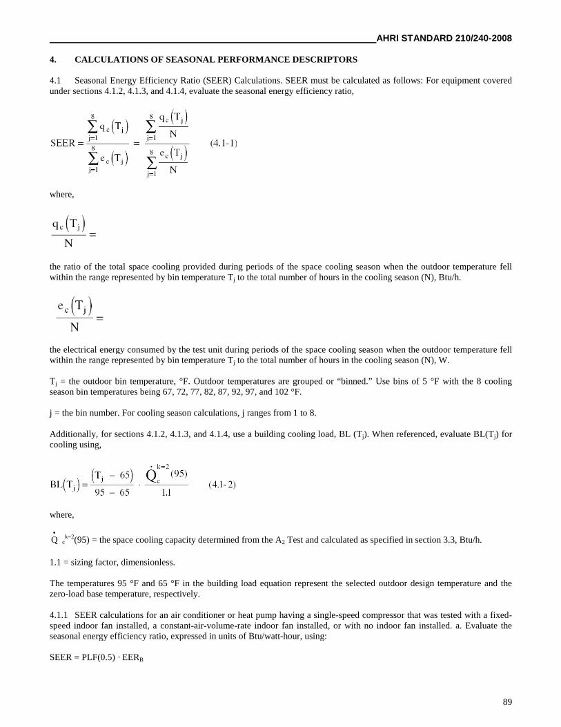
AHRI STANDARD 210/240-2008
89
4. CALCULATIONS OF SEASONAL PERFORMANCE DESCRIPTORS
4.1 Seasonal Energy Efficiency Ratio (SEER) Calculations. SEER must be calculated as follows: For equipment coveredunder sections 4.1.2, 4.1.3, and 4.1.4, evaluate the seasonal energy efficiency ratio,
where,
the ratio of the total space cooling provided during periods of the space cooling season when the outdoor temperature fellwithin the range represented by bin temperature Tj to the total number of hours in the cooling season (N), Btu/h.
the electrical energy consumed by the test unit during periods of the space cooling season when the outdoor temperature fellwithin the range represented by bin temperature Tj to the total number of hours in the cooling season (N), W.
Tj = the outdoor bin temperature, °F. Outdoor temperatures are grouped or “binned.” Use bins of 5 °F with the 8 coolingseason bin temperatures being 67, 72, 77, 82, 87, 92, 97, and 102 °F.
j = the bin number. For cooling season calculations, j ranges from 1 to 8.
Additionally, for sections 4.1.2, 4.1.3, and 4.1.4, use a building cooling load, BL (Tj). When referenced, evaluate BL(Tj) forcooling using,
where,
Q
ck=2(95) = the space cooling capacity determined from the A2 Test and calculated as specified in section 3.3, Btu/h.
1.1 = sizing factor, dimensionless.
The temperatures 95 °F and 65 °F in the building load equation represent the selected outdoor design temperature and thezero-load base temperature, respectively.
4.1.1 SEER calculations for an air conditioner or heat pump having a single-speed compressor that was tested with a fixed-speed indoor fan installed, a constant-air-volume-rate indoor fan installed, or with no indoor fan installed. a. Evaluate theseasonal energy efficiency ratio, expressed in units of Btu/watt-hour, using:
SEER = PLF(0.5) · EERB
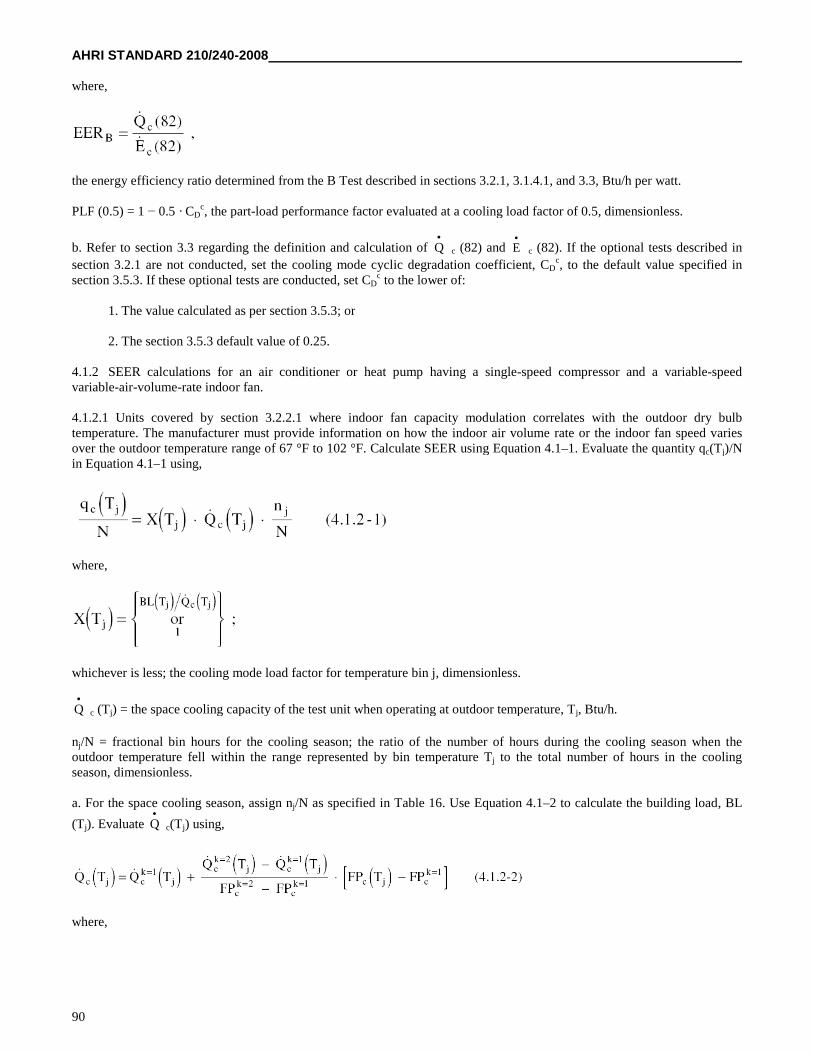
AHRI STANDARD 210/240-2008
90
where,
the energy efficiency ratio determined from the B Test described in sections 3.2.1, 3.1.4.1, and 3.3, Btu/h per watt.
PLF (0.5) = 1 − 0.5 · CDc, the part-load performance factor evaluated at a cooling load factor of 0.5, dimensionless.
b. Refer to section 3.3 regarding the definition and calculation of Q
c (82) and E
c (82). If the optional tests described in
section 3.2.1 are not conducted, set the cooling mode cyclic degradation coefficient, CDc, to the default value specified in
section 3.5.3. If these optional tests are conducted, set CDc to the lower of:
1. The value calculated as per section 3.5.3; or
2. The section 3.5.3 default value of 0.25.
4.1.2 SEER calculations for an air conditioner or heat pump having a single-speed compressor and a variable-speedvariable-air-volume-rate indoor fan.
4.1.2.1 Units covered by section 3.2.2.1 where indoor fan capacity modulation correlates with the outdoor dry bulbtemperature. The manufacturer must provide information on how the indoor air volume rate or the indoor fan speed variesover the outdoor temperature range of 67 °F to 102 °F. Calculate SEER using Equation 4.1–1. Evaluate the quantity qc(Tj)/Nin Equation 4.1–1 using,
where,
whichever is less; the cooling mode load factor for temperature bin j, dimensionless.
Q
c (Tj) = the space cooling capacity of the test unit when operating at outdoor temperature, Tj, Btu/h.
nj/N = fractional bin hours for the cooling season; the ratio of the number of hours during the cooling season when theoutdoor temperature fell within the range represented by bin temperature Tj to the total number of hours in the coolingseason, dimensionless.
a. For the space cooling season, assign nj/N as specified in Table 16. Use Equation 4.1–2 to calculate the building load, BL
(Tj). Evaluate Q
c(Tj) using,
where,
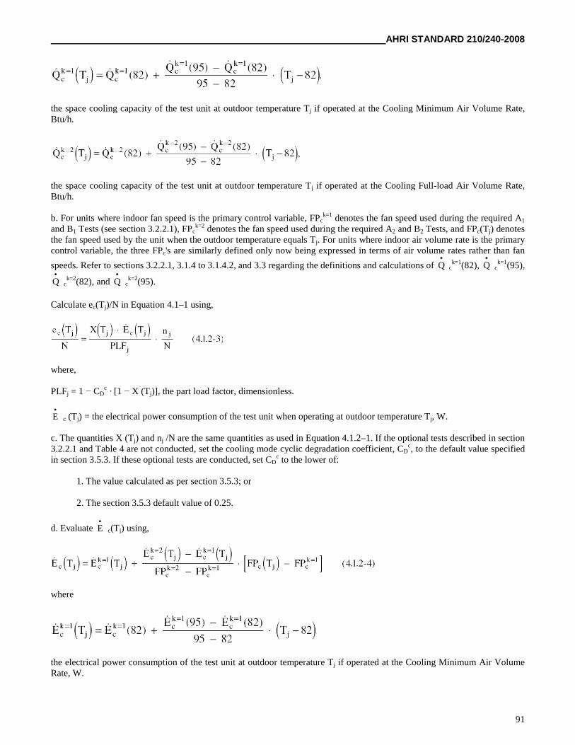
AHRI STANDARD 210/240-2008
91
the space cooling capacity of the test unit at outdoor temperature Tj if operated at the Cooling Minimum Air Volume Rate,Btu/h.
the space cooling capacity of the test unit at outdoor temperature Tj if operated at the Cooling Full-load Air Volume Rate,Btu/h.
b. For units where indoor fan speed is the primary control variable, FPck=1 denotes the fan speed used during the required A1
and B1 Tests (see section 3.2.2.1), FPck=2 denotes the fan speed used during the required A2 and B2 Tests, and FPc(Tj) denotes
the fan speed used by the unit when the outdoor temperature equals Tj. For units where indoor air volume rate is the primarycontrol variable, the three FPc's are similarly defined only now being expressed in terms of air volume rates rather than fan
speeds. Refer to sections 3.2.2.1, 3.1.4 to 3.1.4.2, and 3.3 regarding the definitions and calculations of Q
ck=1(82), Q
ck=1(95),
Q
ck=2(82), and Q
ck=2(95).
Calculate ec(Tj)/N in Equation 4.1–1 using,
where,
PLFj = 1 − CDc · [1 − X (Tj)], the part load factor, dimensionless.
E
c (Tj) = the electrical power consumption of the test unit when operating at outdoor temperature Tj, W.
c. The quantities X (Tj) and nj /N are the same quantities as used in Equation 4.1.2–1. If the optional tests described in section3.2.2.1 and Table 4 are not conducted, set the cooling mode cyclic degradation coefficient, CD
c, to the default value specifiedin section 3.5.3. If these optional tests are conducted, set CD
c to the lower of:
1. The value calculated as per section 3.5.3; or
2. The section 3.5.3 default value of 0.25.
d. Evaluate E
c(Tj) using,
where
the electrical power consumption of the test unit at outdoor temperature Tj if operated at the Cooling Minimum Air VolumeRate, W.
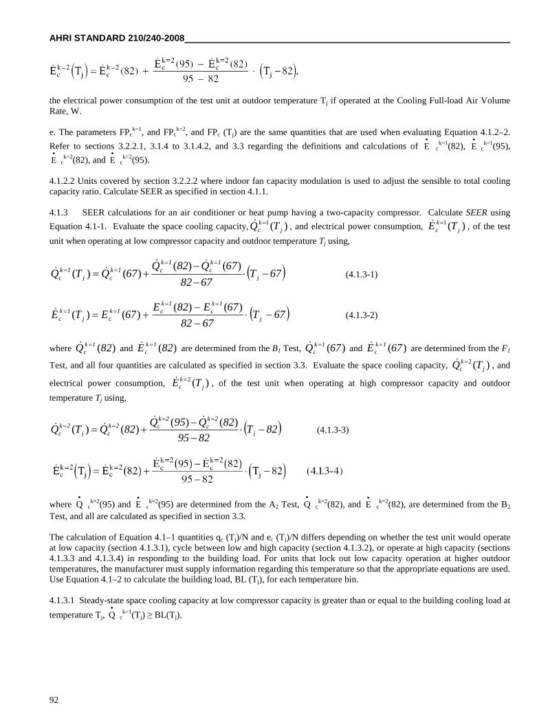
AHRI STANDARD 210/240-2008
92
the electrical power consumption of the test unit at outdoor temperature Tj if operated at the Cooling Full-load Air VolumeRate, W.
e. The parameters FPck=1, and FPc
k=2, and FPc (Tj) are the same quantities that are used when evaluating Equation 4.1.2–2.
Refer to sections 3.2.2.1, 3.1.4 to 3.1.4.2, and 3.3 regarding the definitions and calculations of E
ck=1(82), E
ck=1(95),
E
ck=2(82), and E
ck=2(95).
4.1.2.2 Units covered by section 3.2.2.2 where indoor fan capacity modulation is used to adjust the sensible to total coolingcapacity ratio. Calculate SEER as specified in section 4.1.1.
4.1.3 SEER calculations for an air conditioner or heat pump having a two-capacity compressor. Calculate SEER using
Equation 4.1-1. Evaluate the space cooling capacity, )(1j
kc TQ , and electrical power consumption, )(1
jkc TE , of the test
unit when operating at low compressor capacity and outdoor temperature Tj using,
67T6782
67Q82Q67QTQ j
1kc
1kc1k
cj1k
c
)()(
)()(
(4.1.3-1)
67T6782
67E82E67ETE j
1kc
1kc1k
cj1k
c
)()(
)()( (4.1.3-2)
where )(82Q 1kc and )(82E 1k
c are determined from the B1 Test, )(67Q 1k
c and )(67E 1k
c are determined from the F1
Test, and all four quantities are calculated as specified in section 3.3. Evaluate the space cooling capacity, )(2j
kc TQ , and
electrical power consumption, )(2j
kc TE , of the test unit when operating at high compressor capacity and outdoor
temperature Tj using,
82T8295
82Q95Q82QTQ j
2kc
2kc2k
cj2k
c
)()(
)()(
(4.1.3-3)
where Q
ck=2(95) and E
ck=2(95) are determined from the A2 Test, Q
ck=2(82), and E
ck=2(82), are determined from the B2
Test, and all are calculated as specified in section 3.3.
The calculation of Equation 4.1–1 quantities qc (Tj)/N and ec (Tj)/N differs depending on whether the test unit would operateat low capacity (section 4.1.3.1), cycle between low and high capacity (section 4.1.3.2), or operate at high capacity (sections4.1.3.3 and 4.1.3.4) in responding to the building load. For units that lock out low capacity operation at higher outdoortemperatures, the manufacturer must supply information regarding this temperature so that the appropriate equations are used.Use Equation 4.1–2 to calculate the building load, BL (Tj), for each temperature bin.
4.1.3.1 Steady-state space cooling capacity at low compressor capacity is greater than or equal to the building cooling load at
temperature Tj, Q
ck=1(Tj) ≥ BL(Tj).
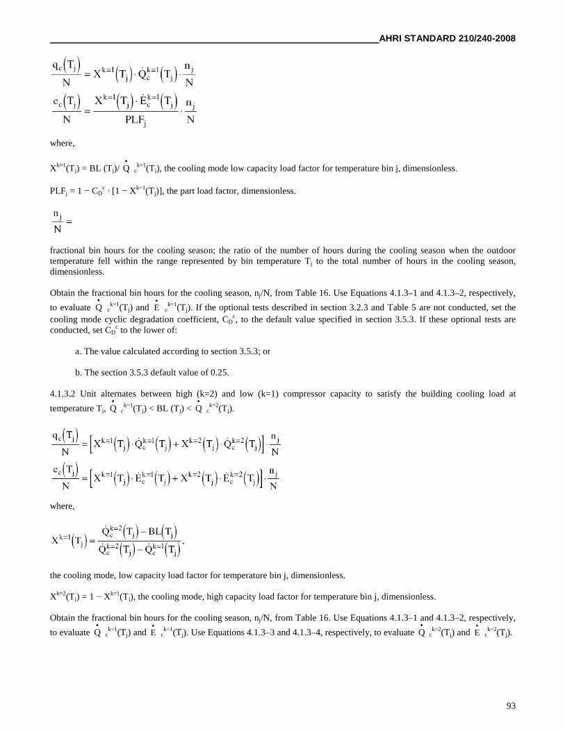
AHRI STANDARD 210/240-2008
93
where,
Xk=1(Tj) = BL (Tj)/ Q
ck=1(Tj), the cooling mode low capacity load factor for temperature bin j, dimensionless.
PLFj = 1 − CDc · [1 − Xk=1(Tj)], the part load factor, dimensionless.
fractional bin hours for the cooling season; the ratio of the number of hours during the cooling season when the outdoortemperature fell within the range represented by bin temperature Tj to the total number of hours in the cooling season,dimensionless.
Obtain the fractional bin hours for the cooling season, nj/N, from Table 16. Use Equations 4.1.3–1 and 4.1.3–2, respectively,
to evaluate Q
ck=1(Tj) and E
ck=1(Tj). If the optional tests described in section 3.2.3 and Table 5 are not conducted, set the
cooling mode cyclic degradation coefficient, CDc, to the default value specified in section 3.5.3. If these optional tests are
conducted, set CDc to the lower of:
a. The value calculated according to section 3.5.3; or
b. The section 3.5.3 default value of 0.25.
4.1.3.2 Unit alternates between high (k=2) and low (k=1) compressor capacity to satisfy the building cooling load at
temperature Tj, Q
ck=1(Tj) < BL (Tj) < Q
ck=2(Tj).
where,
the cooling mode, low capacity load factor for temperature bin j, dimensionless.
Xk=2(Tj) = 1 − Xk=1(Tj), the cooling mode, high capacity load factor for temperature bin j, dimensionless.
Obtain the fractional bin hours for the cooling season, nj/N, from Table 16. Use Equations 4.1.3–1 and 4.1.3–2, respectively,
to evaluate Q
ck=1(Tj) and E
ck=1(Tj). Use Equations 4.1.3–3 and 4.1.3–4, respectively, to evaluate Q
ck=2(Tj) and E
ck=2(Tj).
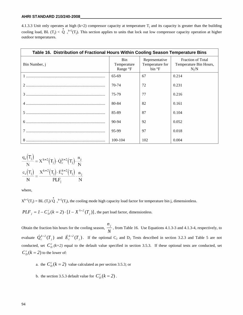
AHRI STANDARD 210/240-2008
94
4.1.3.3 Unit only operates at high (k=2) compressor capacity at temperature Tj and its capacity is greater than the building
cooling load, BL (Tj) < Q
ck=2(Tj). This section applies to units that lock out low compressor capacity operation at higher
outdoor temperatures.
Table 16. Distribution of Fractional Hours Within Cooling Season Temperature Bins
Bin Number, jBin
TemperatureRange °F
RepresentativeTemperature for
bin °F
Fraction of TotalTemperature Bin Hours,
Nj/N
1 ...............................................................................
2 ...............................................................................
3 ...............................................................................
4 ...............................................................................
5 ...............................................................................
6 ...............................................................................
7 ...............................................................................
8 ...............................................................................
65-69
70-74
75-79
80-84
85-89
90-94
95-99
100-104
67
72
77
82
87
92
97
102
0.214
0.231
0.216
0.161
0.104
0.052
0.018
0.004
where,
Xk=2(Tj) = BL (Tj)/ Q
ck=2(Tj), the cooling mode high capacity load factor for temperature bin j, dimensionless.
)]([)( j2kc
Dj TX12kC1PLF , the part load factor, dimensionless.
Obtain the fraction bin hours for the cooling season,N
n j, from Table 16. Use Equations 4.1.3-3 and 4.1.3-4, respectively, to
evaluate )( j2k
c TQ and )( j2k
c TE . If the optional C2 and D2 Tests described in section 3.2.3 and Table 5 are not
conducted, setcDC (k=2) equal to the default value specified in section 3.5.3. If these optional tests are conducted, set
)( 2kC cD to the lower of:
a. the )( 2kC cD value calculated as per section 3.5.3; or
b. the section 3.5.3 default value for )( 2kC cD .
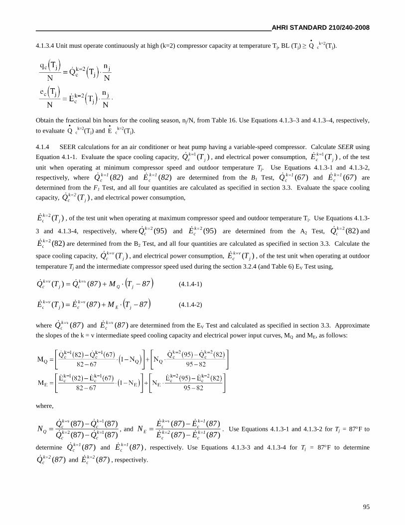
AHRI STANDARD 210/240-2008
95
4.1.3.4 Unit must operate continuously at high (k=2) compressor capacity at temperature Tj, BL (Tj) ≥ Q
ck=2(Tj).
Obtain the fractional bin hours for the cooling season, nj/N, from Table 16. Use Equations 4.1.3–3 and 4.1.3–4, respectively,
to evaluate Q
ck=2(Tj) and E
ck=2(Tj).
4.1.4 SEER calculations for an air conditioner or heat pump having a variable-speed compressor. Calculate SEER using
Equation 4.1-1. Evaluate the space cooling capacity, )(1j
kc TQ , and electrical power consumption, )(1
jkc TE , of the test
unit when operating at minimum compressor speed and outdoor temperature Tj. Use Equations 4.1.3-1 and 4.1.3-2,
respectively, where )(82Q 1kc and )(82E 1k
c are determined from the B1 Test, )(67Q 1k
c and )(67E 1k
c are
determined from the F1 Test, and all four quantities are calculated as specified in section 3.3. Evaluate the space cooling
capacity, )( j2k
c TQ , and electrical power consumption,
)(2j
kc TE , of the test unit when operating at maximum compressor speed and outdoor temperature Tj. Use Equations 4.1.3-
3 and 4.1.3-4, respectively, where )95(2kcQ and )95(2k
cE are determined from the A2 Test, )82(2kcQ and
)82(2kcE are determined from the B2 Test, and all four quantities are calculated as specified in section 3.3. Calculate the
space cooling capacity, )( jvk
c TQ , and electrical power consumption, )( jvk
c TE , of the test unit when operating at outdoor
temperature Tj and the intermediate compressor speed used during the section 3.2.4 (and Table 6) EV Test using,
87TM87QTQ jQvk
cjvk
c )()( (4.1.4-1)
87TM87ETE jEvk
cjvk
c )()( (4.1.4-2)
where )(87Q vkc and )(87E vk
c are determined from the EV Test and calculated as specified in section 3.3. Approximate
the slopes of the k = v intermediate speed cooling capacity and electrical power input curves, MQ and ME, as follows:
where,
)87()87(
)87()87(12
1
kc
kc
kc
vkc
QQQ
QQN
, and
)()(
)()(
87E87E
87E87EN
1kc
2kc
1kc
vkc
E
. Use Equations 4.1.3-1 and 4.1.3-2 for Tj = 87F to
determine )(87Q 1kc and )(87E 1k
c , respectively. Use Equations 4.1.3-3 and 4.1.3-4 for Tj = 87F to determine
)(87Q 2kc and )(87E 2k
c , respectively.
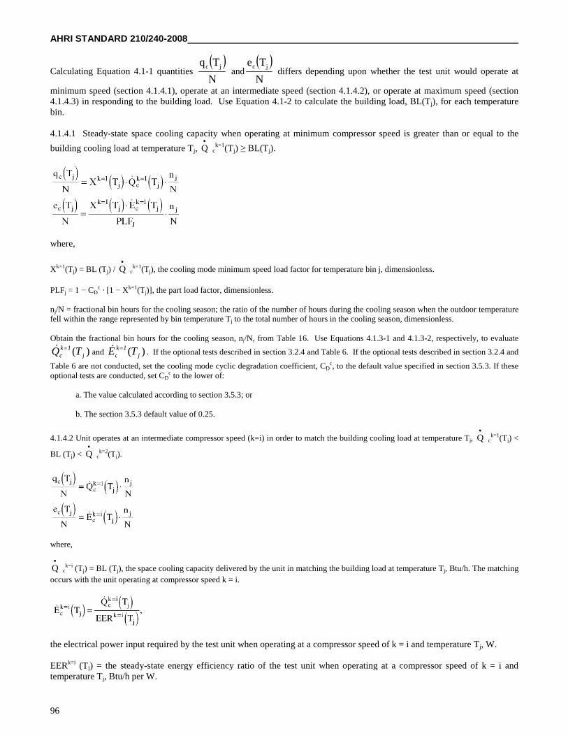
AHRI STANDARD 210/240-2008
96
Calculating Equation 4.1-1 quantities N
Tq jcand
N
Te jcdiffers depending upon whether the test unit would operate at
minimum speed (section 4.1.4.1), operate at an intermediate speed (section 4.1.4.2), or operate at maximum speed (section4.1.4.3) in responding to the building load. Use Equation 4.1-2 to calculate the building load, BL(Tj), for each temperaturebin.
4.1.4.1 Steady-state space cooling capacity when operating at minimum compressor speed is greater than or equal to the
building cooling load at temperature Tj, Q
ck=1(Tj) ≥ BL(Tj).
where,
Xk=1(Tj) = BL (Tj) / Q
ck=1(Tj), the cooling mode minimum speed load factor for temperature bin j, dimensionless.
PLFj = 1 − CDc · [1 − Xk=1(Tj)], the part load factor, dimensionless.
nj/N = fractional bin hours for the cooling season; the ratio of the number of hours during the cooling season when the outdoor temperaturefell within the range represented by bin temperature Tj to the total number of hours in the cooling season, dimensionless.
Obtain the fractional bin hours for the cooling season, nj/N, from Table 16. Use Equations 4.1.3-1 and 4.1.3-2, respectively, to evaluate
)( j1k
c TQ and )( j1k
c TE . If the optional tests described in section 3.2.4 and Table 6. If the optional tests described in section 3.2.4 and
Table 6 are not conducted, set the cooling mode cyclic degradation coefficient, CDc, to the default value specified in section 3.5.3. If these
optional tests are conducted, set CDc to the lower of:
a. The value calculated according to section 3.5.3; or
b. The section 3.5.3 default value of 0.25.
4.1.4.2 Unit operates at an intermediate compressor speed (k=i) in order to match the building cooling load at temperature Tj, Q
ck=1(Tj) <
BL (Tj) < Q
ck=2(Tj).
where,
Q
ck=i (Tj) = BL (Tj), the space cooling capacity delivered by the unit in matching the building load at temperature Tj, Btu/h. The matching
occurs with the unit operating at compressor speed k = i.
the electrical power input required by the test unit when operating at a compressor speed of k = i and temperature Tj, W.
EERk=i (Tj) = the steady-state energy efficiency ratio of the test unit when operating at a compressor speed of k = i andtemperature Tj, Btu/h per W.
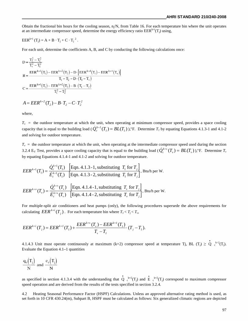
AHRI STANDARD 210/240-2008
97
Obtain the fractional bin hours for the cooling season, nj/N, from Table 16. For each temperature bin where the unit operatesat an intermediate compressor speed, determine the energy efficiency ratio EERk=i(Tj) using,
EERk=i (Tj) = A + B · Tj + C · Tj2 .
For each unit, determine the coefficients A, B, and C by conducting the following calculations once:
2222
2k TCTBTEERA )(
where,
T1 = the outdoor temperature at which the unit, when operating at minimum compressor speed, provides a space cooling
capacity that is equal to the building load ( )()( 111k
c TBLTQ ),F. Determine T1 by equating Equations 4.1.3-1 and 4.1-2
and solving for outdoor temperature.
Tv = the outdoor temperature at which the unit, when operating at the intermediate compressor speed used during the section
3.2.4 EV Test, provides a space cooling capacity that is equal to the building load ( )()( vvvk
c TBLTQ ),F. Determine Tv
by equating Equations 4.1.4-1 and 4.1-2 and solving for outdoor temperature.
j
kc
jkck
TTTE
TTTQTEER
forngsubstituti2,-4.1.3Eqn.)(
forngsubstituti1,-4.1.3Eqn.)()(
111
111
11
, Btu/h per W.
jvv
vkc
jvvvk
c
vvk
TTTE
TTTQTEER
forngsubstituti2,-4.1.4Eqn.)(
forngsubstituti1,-4.1.4Eqn.)()(
, Btu/h per W.
For multiple-split air conditioners and heat pumps (only), the following procedures supersede the above requirements for
calculating )( jik TEER
. For each temperature bin where T1 < Tj < Tv,
).()()(
)()( 1j
1v
11k
vvk
11k
jik TT
TT
TEERTEERTEERTEER
4.1.4.3 Unit must operate continuously at maximum (k=2) compressor speed at temperature Tj, BL (Tj) ≥ Q
ck=2(Tj).
Evaluate the Equation 4.1–1 quantities
as specified in section 4.1.3.4 with the understanding that Q
ck=2(Tj) and E
ck=2(Tj) correspond to maximum compressor
speed operation and are derived from the results of the tests specified in section 3.2.4.
4.2 Heating Seasonal Performance Factor (HSPF) Calculations. Unless an approved alternative rating method is used, asset forth in 10 CFR 430.24(m), Subpart B, HSPF must be calculated as follows: Six generalized climatic regions are depicted
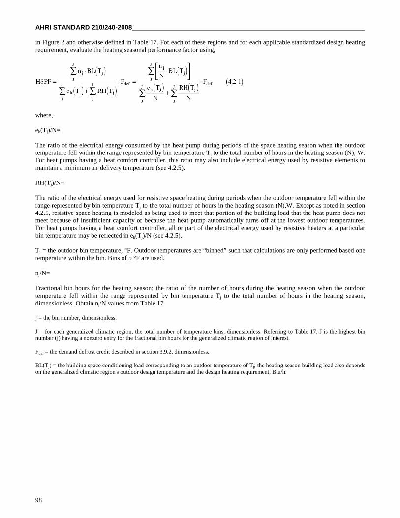
AHRI STANDARD 210/240-2008
98
in Figure 2 and otherwise defined in Table 17. For each of these regions and for each applicable standardized design heatingrequirement, evaluate the heating seasonal performance factor using,
where,
eh(Tj)/N=
The ratio of the electrical energy consumed by the heat pump during periods of the space heating season when the outdoortemperature fell within the range represented by bin temperature Tj to the total number of hours in the heating season (N), W.For heat pumps having a heat comfort controller, this ratio may also include electrical energy used by resistive elements tomaintain a minimum air delivery temperature (see 4.2.5).
RH(Tj)/N=
The ratio of the electrical energy used for resistive space heating during periods when the outdoor temperature fell within therange represented by bin temperature Tj to the total number of hours in the heating season (N),W. Except as noted in section4.2.5, resistive space heating is modeled as being used to meet that portion of the building load that the heat pump does notmeet because of insufficient capacity or because the heat pump automatically turns off at the lowest outdoor temperatures.For heat pumps having a heat comfort controller, all or part of the electrical energy used by resistive heaters at a particularbin temperature may be reflected in eh(Tj)/N (see 4.2.5).
Tj = the outdoor bin temperature, °F. Outdoor temperatures are “binned” such that calculations are only performed based onetemperature within the bin. Bins of 5 °F are used.
nj/N=
Fractional bin hours for the heating season; the ratio of the number of hours during the heating season when the outdoortemperature fell within the range represented by bin temperature Tj to the total number of hours in the heating season,dimensionless. Obtain nj/N values from Table 17.
j = the bin number, dimensionless.
J = for each generalized climatic region, the total number of temperature bins, dimensionless. Referring to Table 17, J is the highest binnumber (j) having a nonzero entry for the fractional bin hours for the generalized climatic region of interest.
Fdef = the demand defrost credit described in section 3.9.2, dimensionless.
BL(Tj) = the building space conditioning load corresponding to an outdoor temperature of Tj; the heating season building load also dependson the generalized climatic region's outdoor design temperature and the design heating requirement, Btu/h.
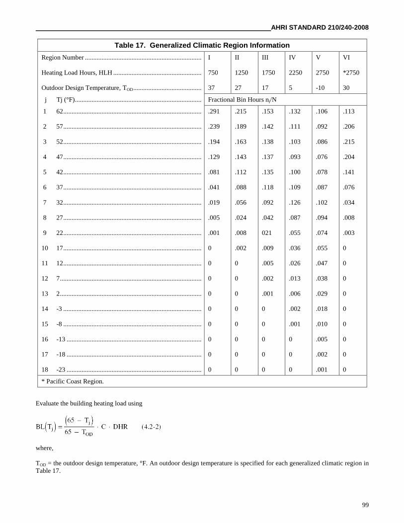
AHRI STANDARD 210/240-2008
99
Table 17. Generalized Climatic Region Information
Region Number ......................................................................
Heating Load Hours, HLH .....................................................
Outdoor Design Temperature, TOD.........................................
I
750
37
II
1250
27
III
1750
17
IV
2250
5
V
2750
-10
VI
*2750
30
j Tj (°F)............................................................................ Fractional Bin Hours nj/N
1 62...................................................................................
2 57...................................................................................
3 52...................................................................................
4 47...................................................................................
5 42...................................................................................
6 37...................................................................................
7 32...................................................................................
8 27...................................................................................
9 22...................................................................................
10 17...................................................................................
11 12...................................................................................
12 7.....................................................................................
13 2.....................................................................................
14 -3 ...................................................................................
15 -8 ...................................................................................
16 -13 .................................................................................
17 -18 .................................................................................
18 -23 .................................................................................
.291
.239
.194
.129
.081
.041
.019
.005
.001
0
0
0
0
0
0
0
0
0
.215
.189
.163
.143
.112
.088
.056
.024
.008
.002
0
0
0
0
0
0
0
0
.153
.142
.138
.137
.135
.118
.092
.042
021
.009
.005
.002
.001
0
0
0
0
0
.132
.111
.103
.093
.100
.109
.126
.087
.055
.036
.026
.013
.006
.002
.001
0
0
0
.106
.092
.086
.076
.078
.087
.102
.094
.074
.055
.047
.038
.029
.018
.010
.005
.002
.001
.113
.206
.215
.204
.141
.076
.034
.008
.003
0
0
0
0
0
0
0
0
0
* Pacific Coast Region.
Evaluate the building heating load using
where,
TOD = the outdoor design temperature, °F. An outdoor design temperature is specified for each generalized climatic region inTable 17.
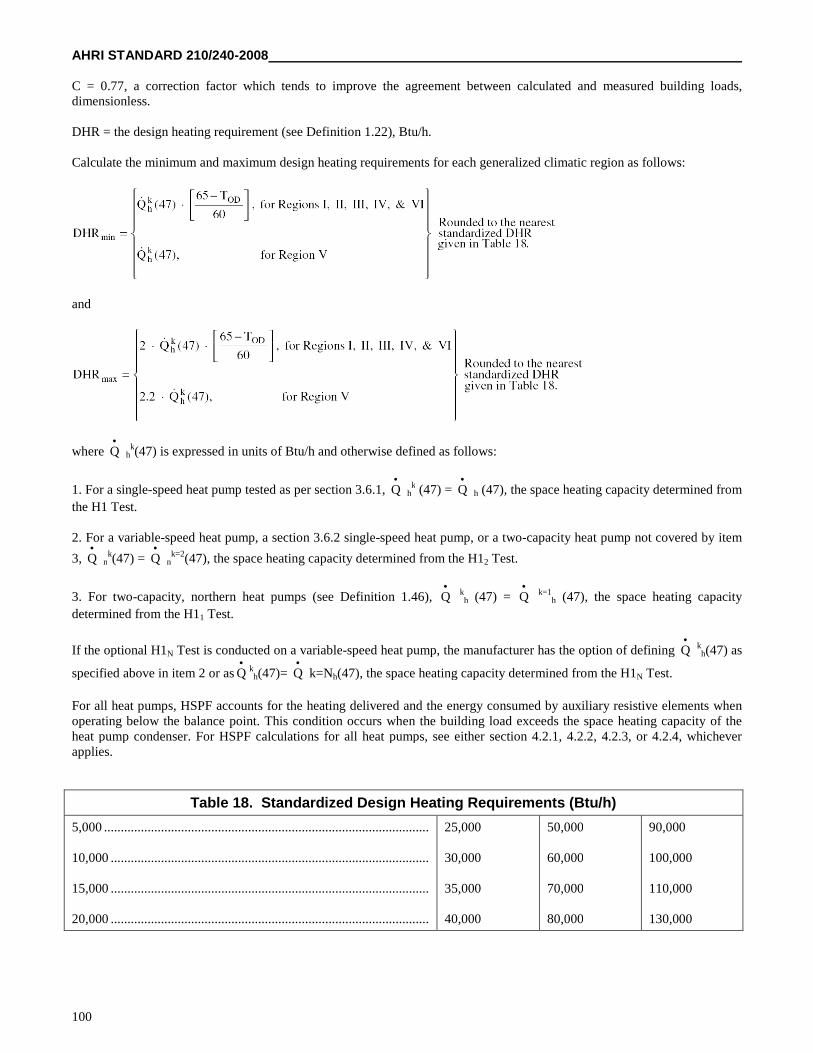
AHRI STANDARD 210/240-2008
100
C = 0.77, a correction factor which tends to improve the agreement between calculated and measured building loads,dimensionless.
DHR = the design heating requirement (see Definition 1.22), Btu/h.
Calculate the minimum and maximum design heating requirements for each generalized climatic region as follows:
and
where Q
hk(47) is expressed in units of Btu/h and otherwise defined as follows:
1. For a single-speed heat pump tested as per section 3.6.1, Q
hk (47) = Q
h (47), the space heating capacity determined from
the H1 Test.
2. For a variable-speed heat pump, a section 3.6.2 single-speed heat pump, or a two-capacity heat pump not covered by item
3, Q
nk(47) = Q
nk=2(47), the space heating capacity determined from the H12 Test.
3. For two-capacity, northern heat pumps (see Definition 1.46), Q
kh (47) = Q
k=1
h (47), the space heating capacity
determined from the H11 Test.
If the optional H1N Test is conducted on a variable-speed heat pump, the manufacturer has the option of defining Q
kh(47) as
specified above in item 2 or as Q
kh(47)= Q
k=Nh(47), the space heating capacity determined from the H1N Test.
For all heat pumps, HSPF accounts for the heating delivered and the energy consumed by auxiliary resistive elements whenoperating below the balance point. This condition occurs when the building load exceeds the space heating capacity of theheat pump condenser. For HSPF calculations for all heat pumps, see either section 4.2.1, 4.2.2, 4.2.3, or 4.2.4, whicheverapplies.
Table 18. Standardized Design Heating Requirements (Btu/h)
5,000 .................................................................................................
10,000 ...............................................................................................
15,000 ...............................................................................................
20,000 ...............................................................................................
25,000
30,000
35,000
40,000
50,000
60,000
70,000
80,000
90,000
100,000
110,000
130,000
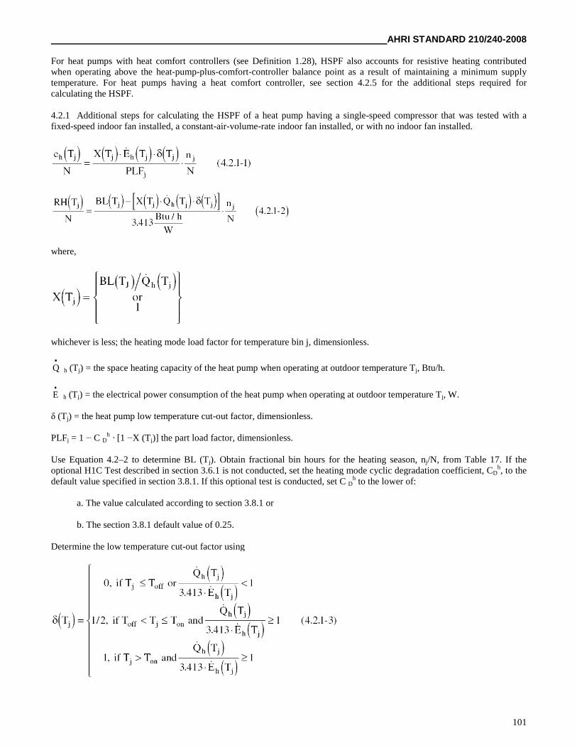
AHRI STANDARD 210/240-2008
101
For heat pumps with heat comfort controllers (see Definition 1.28), HSPF also accounts for resistive heating contributedwhen operating above the heat-pump-plus-comfort-controller balance point as a result of maintaining a minimum supplytemperature. For heat pumps having a heat comfort controller, see section 4.2.5 for the additional steps required forcalculating the HSPF.
4.2.1 Additional steps for calculating the HSPF of a heat pump having a single-speed compressor that was tested with afixed-speed indoor fan installed, a constant-air-volume-rate indoor fan installed, or with no indoor fan installed.
where,
whichever is less; the heating mode load factor for temperature bin j, dimensionless.
Q
h (Tj) = the space heating capacity of the heat pump when operating at outdoor temperature Tj, Btu/h.
E
h (Tj) = the electrical power consumption of the heat pump when operating at outdoor temperature Tj, W.
δ (Tj) = the heat pump low temperature cut-out factor, dimensionless.
PLFj = 1 − C Dh · [1 −X (Tj)] the part load factor, dimensionless.
Use Equation 4.2–2 to determine BL (Tj). Obtain fractional bin hours for the heating season, nj/N, from Table 17. If theoptional H1C Test described in section 3.6.1 is not conducted, set the heating mode cyclic degradation coefficient, CD
h, to thedefault value specified in section 3.8.1. If this optional test is conducted, set C D
h to the lower of:
a. The value calculated according to section 3.8.1 or
b. The section 3.8.1 default value of 0.25.
Determine the low temperature cut-out factor using
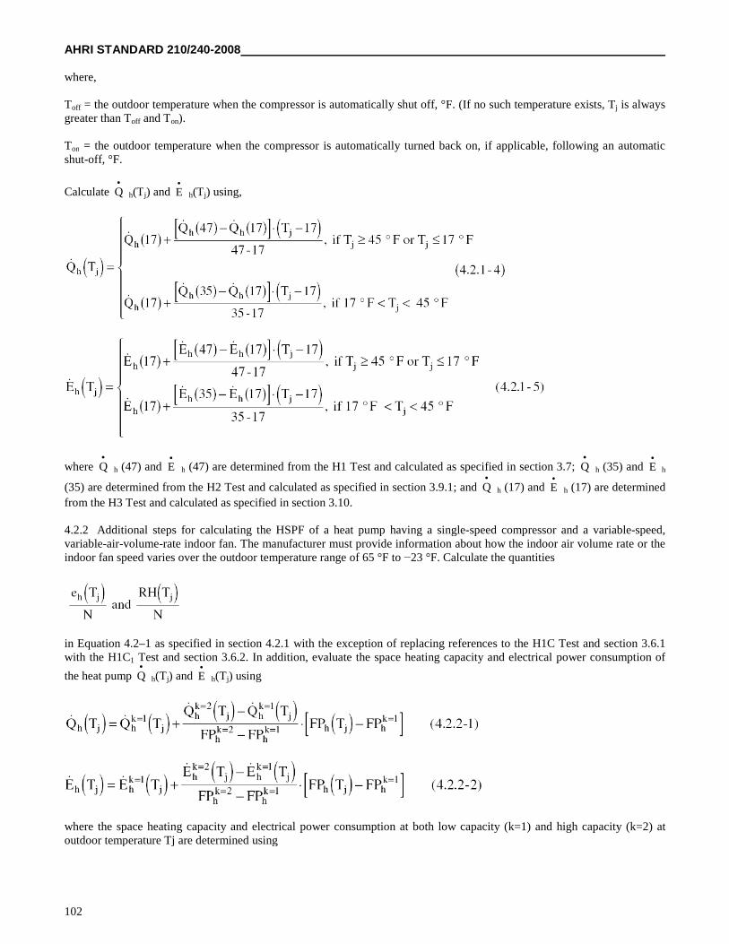
AHRI STANDARD 210/240-2008
102
where,
Toff = the outdoor temperature when the compressor is automatically shut off, °F. (If no such temperature exists, Tj is alwaysgreater than Toff and Ton).
Ton = the outdoor temperature when the compressor is automatically turned back on, if applicable, following an automaticshut-off, °F.
Calculate Q
h(Tj) and E
h(Tj) using,
where Q
h (47) and E
h (47) are determined from the H1 Test and calculated as specified in section 3.7; Q
h (35) and E
h
(35) are determined from the H2 Test and calculated as specified in section 3.9.1; and Q
h (17) and E
h (17) are determined
from the H3 Test and calculated as specified in section 3.10.
4.2.2 Additional steps for calculating the HSPF of a heat pump having a single-speed compressor and a variable-speed,variable-air-volume-rate indoor fan. The manufacturer must provide information about how the indoor air volume rate or theindoor fan speed varies over the outdoor temperature range of 65 °F to −23 °F. Calculate the quantities
in Equation 4.2–1 as specified in section 4.2.1 with the exception of replacing references to the H1C Test and section 3.6.1with the H1C1 Test and section 3.6.2. In addition, evaluate the space heating capacity and electrical power consumption of
the heat pump Q
h(Tj) and E
h(Tj) using
where the space heating capacity and electrical power consumption at both low capacity (k=1) and high capacity (k=2) atoutdoor temperature Tj are determined using
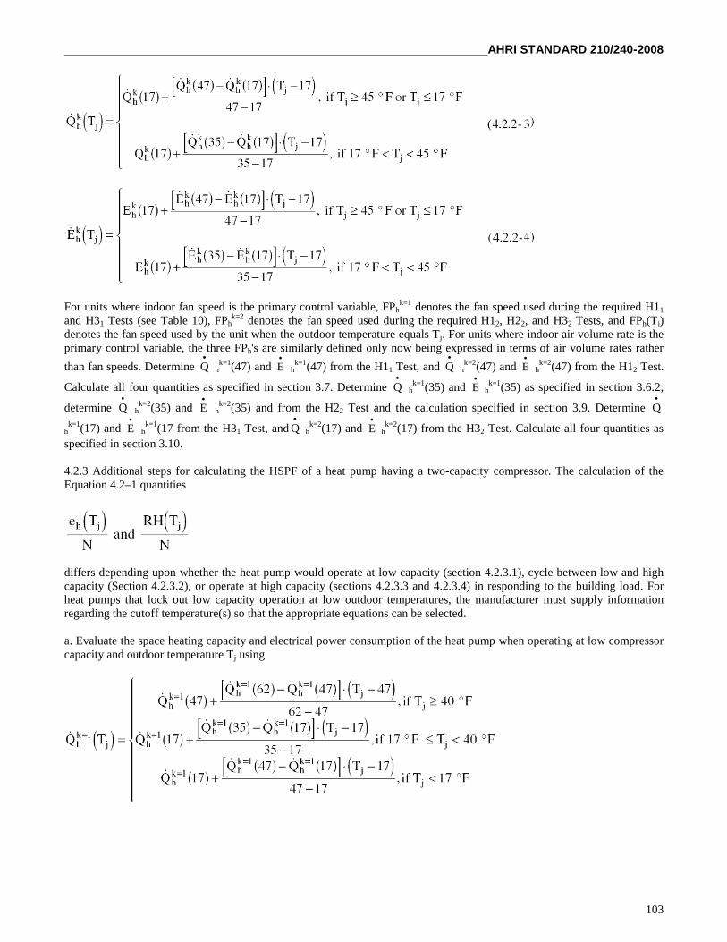
AHRI STANDARD 210/240-2008
103
For units where indoor fan speed is the primary control variable, FPhk=1 denotes the fan speed used during the required H11
and H31 Tests (see Table 10), FPhk=2 denotes the fan speed used during the required H12, H22, and H32 Tests, and FPh(Tj)
denotes the fan speed used by the unit when the outdoor temperature equals Tj. For units where indoor air volume rate is theprimary control variable, the three FPh's are similarly defined only now being expressed in terms of air volume rates rather
than fan speeds. Determine Q
hk=1(47) and E
hk=1(47) from the H11 Test, and Q
hk=2(47) and E
hk=2(47) from the H12 Test.
Calculate all four quantities as specified in section 3.7. Determine Q
hk=1(35) and E
hk=1(35) as specified in section 3.6.2;
determine Q
hk=2(35) and E
hk=2(35) and from the H22 Test and the calculation specified in section 3.9. Determine Q
hk=1(17) and E
hk=1(17 from the H31 Test, and Q
hk=2(17) and E
hk=2(17) from the H32 Test. Calculate all four quantities as
specified in section 3.10.
4.2.3 Additional steps for calculating the HSPF of a heat pump having a two-capacity compressor. The calculation of theEquation 4.2–1 quantities
differs depending upon whether the heat pump would operate at low capacity (section 4.2.3.1), cycle between low and highcapacity (Section 4.2.3.2), or operate at high capacity (sections 4.2.3.3 and 4.2.3.4) in responding to the building load. Forheat pumps that lock out low capacity operation at low outdoor temperatures, the manufacturer must supply informationregarding the cutoff temperature(s) so that the appropriate equations can be selected.
a. Evaluate the space heating capacity and electrical power consumption of the heat pump when operating at low compressorcapacity and outdoor temperature Tj using
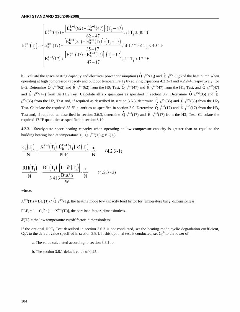
AHRI STANDARD 210/240-2008
104
b. Evaluate the space heating capacity and electrical power consumption ( Q
hk=2(Tj) and E
hk=2 (Tj)) of the heat pump when
operating at high compressor capacity and outdoor temperature Tj by solving Equations 4.2.2–3 and 4.2.2–4, respectively, for
k=2. Determine Q
hk=1(62) and E
hk=1(62) from the H01 Test, Q
hk=1(47) and E
hk=1(47) from the H11 Test, and Q
hk=2(47)
and E
hk=2(47) from the H12 Test. Calculate all six quantities as specified in section 3.7. Determine Q
hk=2(35) and E
hk=2(35) from the H22 Test and, if required as described in section 3.6.3, determine Q
hk=1(35) and E
hk=1(35) from the H21
Test. Calculate the required 35 °F quantities as specified in section 3.9. Determine Q
hk=2(17) and E
hk=2(17) from the H32
Test and, if required as described in section 3.6.3, determine Q
hk=1(17) and E
hk=1(17) from the H31 Test. Calculate the
required 17 °F quantities as specified in section 3.10.
4.2.3.1 Steady-state space heating capacity when operating at low compressor capacity is greater than or equal to the
building heating load at temperature Tj, Q
hk=1(Tj) ≥ BL(Tj).
where,
Xk=1(Tj) = BL (Tj) / Q
hk=1(Tj), the heating mode low capacity load factor for temperature bin j, dimensionless.
PLFj = 1 − CDh · [1 − Xk=1(Tj)], the part load factor, dimensionless.
δ'(Tj) = the low temperature cutoff factor, dimensionless.
If the optional H0C1 Test described in section 3.6.3 is not conducted, set the heating mode cyclic degradation coefficient,CD
h, to the default value specified in section 3.8.1. If this optional test is conducted, set CDh to the lower of:
a. The value calculated according to section 3.8.1; or
b. The section 3.8.1 default value of 0.25.
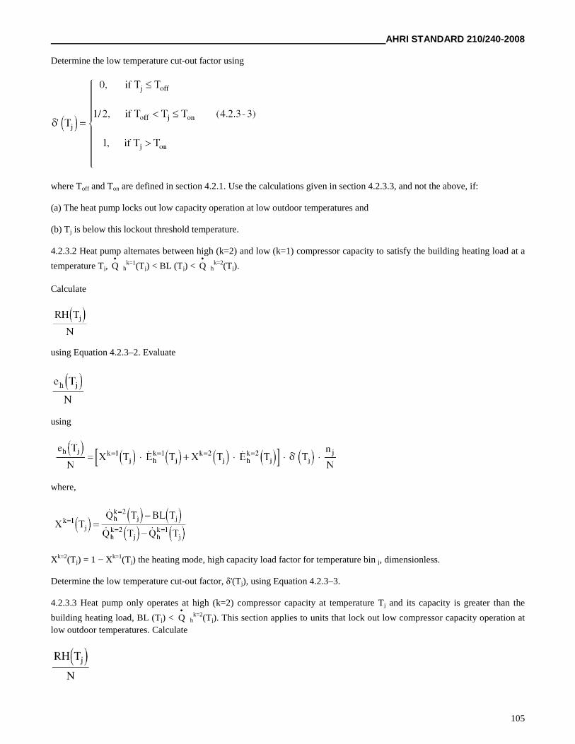
AHRI STANDARD 210/240-2008
105
Determine the low temperature cut-out factor using
where Toff and Ton are defined in section 4.2.1. Use the calculations given in section 4.2.3.3, and not the above, if:
(a) The heat pump locks out low capacity operation at low outdoor temperatures and
(b) Tj is below this lockout threshold temperature.
4.2.3.2 Heat pump alternates between high (k=2) and low (k=1) compressor capacity to satisfy the building heating load at a
temperature Tj, Q
hk=1(Tj) < BL (Tj) < Q
hk=2(Tj).
Calculate
using Equation 4.2.3–2. Evaluate
using
where,
Xk=2(Tj) = 1 − Xk=1(Tj) the heating mode, high capacity load factor for temperature bin j, dimensionless.
Determine the low temperature cut-out factor, δ'(Tj), using Equation 4.2.3–3.
4.2.3.3 Heat pump only operates at high (k=2) compressor capacity at temperature Tj and its capacity is greater than the
building heating load, BL (Tj) < Q
hk=2(Tj). This section applies to units that lock out low compressor capacity operation at
low outdoor temperatures. Calculate
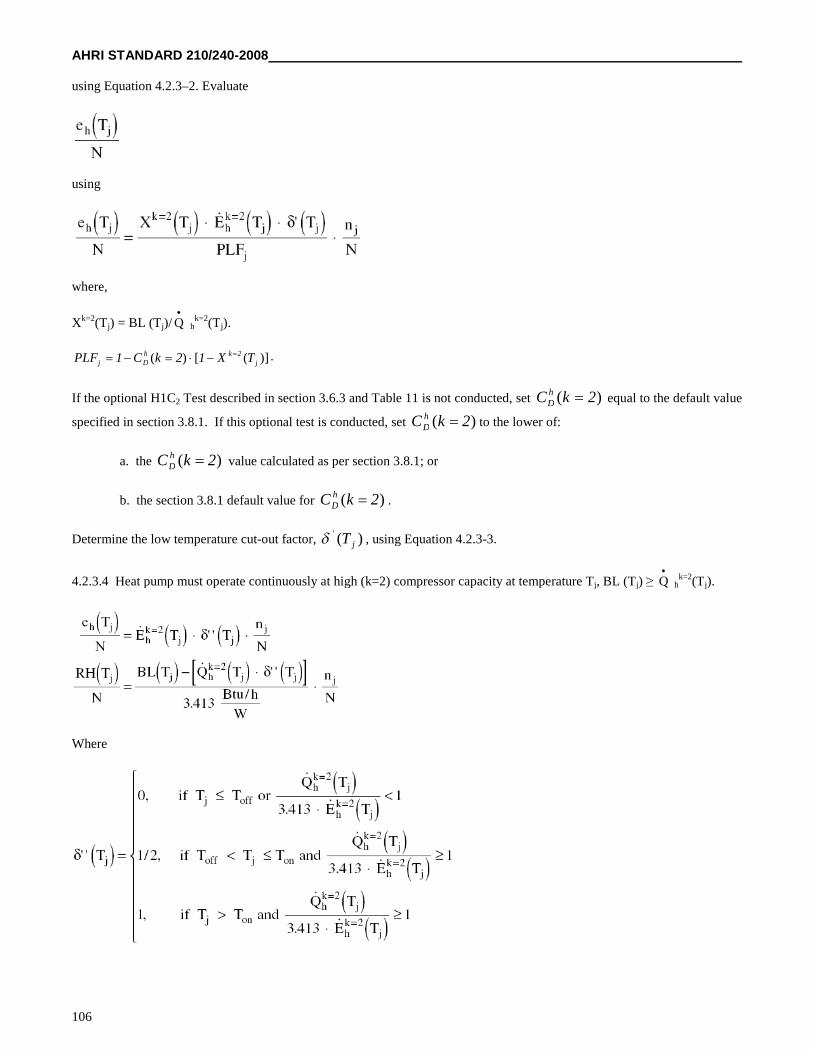
AHRI STANDARD 210/240-2008
106
using Equation 4.2.3–2. Evaluate
using
where,
Xk=2(Tj) = BL (Tj)/ Q
hk=2(Tj).
)]([)( j2kh
Dj TX12kC1PLF .
If the optional H1C2 Test described in section 3.6.3 and Table 11 is not conducted, set )( 2kC hD equal to the default value
specified in section 3.8.1. If this optional test is conducted, set )( 2kC hD to the lower of:
a. the )( 2kC hD value calculated as per section 3.8.1; or
b. the section 3.8.1 default value for )( 2kC hD .
Determine the low temperature cut-out factor, )('jT , using Equation 4.2.3-3.
4.2.3.4 Heat pump must operate continuously at high (k=2) compressor capacity at temperature Tj, BL (Tj) ≥ Q
hk=2(Tj).
Where
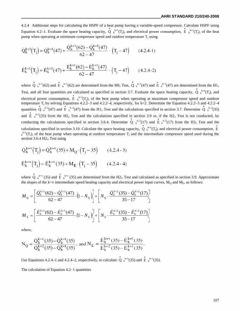
AHRI STANDARD 210/240-2008
107
4.2.4 Additional steps for calculating the HSPF of a heat pump having a variable-speed compressor. Calculate HSPF using
Equation 4.2–1. Evaluate the space heating capacity, Q
hk=1(Tj), and electrical power consumption, E
hk=1(Tj), of the heat
pump when operating at minimum compressor speed and outdoor temperature Tj using
where Q
hk=1(62) and E
hk=1(62) are determined from the H01 Test, Q
hk=1(47) and E
hk=1(47) are determined from the H11
Test, and all four quantities are calculated as specified in section 3.7. Evaluate the space heating capacity, Q
hk=2(Tj), and
electrical power consumption, E
hk=2(Tj), of the heat pump when operating at maximum compressor speed and outdoor
temperature Tj by solving Equations 4.2.2–3 and 4.2.2–4, respectively, for k=2. Determine the Equation 4.2.2–3 and 4.2.2–4
quantities Q
hk=2(47) and E
hk=2(47) from the H12 Test and the calculations specified in section 3.7. Determine Q
hk=2(35)
and E
hk=2(35) from the H22 Test and the calculations specified in section 3.9 or, if the H22 Test is not conducted, by
conducting the calculations specified in section 3.6.4. Determine Q
hk=2(17) and E
hk=2(17) from the H32 Test and the
calculations specified in section 3.10. Calculate the space heating capacity, Q
hk=v(Tj), and electrical power consumption, E
hk=v(Tj), of the heat pump when operating at outdoor temperature Tj and the intermediate compressor speed used during the
section 3.6.4 H2V Test using
where Q
hk=v (35) and E
hk=v (35) are determined from the H2V Test and calculated as specified in section 3.9. Approximate
the slopes of the k=v intermediate speed heating capacity and electrical power input curves, MQ and ME, as follows:
1735
)17()35(1
4762
)47()62( 2211 kh
kh
kh
kh
Q
QQNN
QQM
1735
)17()35(1
4762
)47()62( 2211 kh
kh
EE
kh
kh
E
EENN
EEM
where,
Use Equations 4.2.4–1 and 4.2.4–2, respectively, to calculate Q
hk=1(35) and E
hk=1(35).
The calculation of Equation 4.2–1 quantities
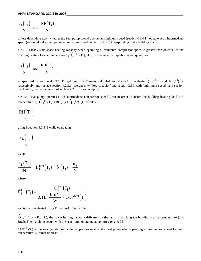
AHRI STANDARD 210/240-2008
108
differs depending upon whether the heat pump would operate at minimum speed (section 4.2.4.1), operate at an intermediatespeed (section 4.2.4.2), or operate at maximum speed (section 4.2.4.3) in responding to the building load.
4.2.4.1 Steady-state space heating capacity when operating at minimum compressor speed is greater than or equal to the
building heating load at temperature Tj, Q
hk=1(Tj ≥ BL(Tj). Evaluate the Equation 4.2–1 quantities
as specified in section 4.2.3.1. Except now use Equations 4.2.4–1 and 4.2.4–2 to evaluate Q
hk=1(Tj) and E
hk=1(Tj),
respectively, and replace section 4.2.3.1 references to “low capacity” and section 3.6.3 with “minimum speed” and section3.6.4. Also, the last sentence of section 4.2.3.1 does not apply.
4.2.4.2 Heat pump operates at an intermediate compressor speed (k=i) in order to match the building heating load at a
temperature Tj, Q
hk=1(Tj) < BL (Tj) < Q
hk=2(Tj). Calculate
using Equation 4.2.3–2 while evaluating
using,
where,
and δ(Tj) is evaluated using Equation 4.2.3–3 while,
Q
hk=i (Tj) = BL (Tj), the space heating capacity delivered by the unit in matching the building load at temperature (Tj),
Btu/h. The matching occurs with the heat pump operating at compressor speed k=i.
COPk=i (Tj) = the steady-state coefficient of performance of the heat pump when operating at compressor speed k=i andtemperature Tj, dimensionless.
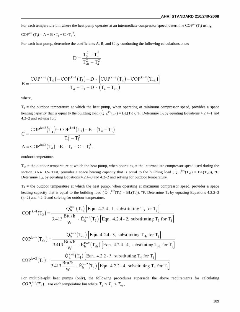
AHRI STANDARD 210/240-2008
109
For each temperature bin where the heat pump operates at an intermediate compressor speed, determine COPk=i(Tj) using,
COPk=i (Tj) = A + B · Tj + C · Tj2.
For each heat pump, determine the coefficients A, B, and C by conducting the following calculations once:
where,
T3 = the outdoor temperature at which the heat pump, when operating at minimum compressor speed, provides a space
heating capacity that is equal to the building load ( Q
hk=1(T3) = BL(T3)), °F. Determine T3 by equating Equations 4.2.4–1 and
4.2–2 and solving for:
outdoor temperature.
Tvh = the outdoor temperature at which the heat pump, when operating at the intermediate compressor speed used during the
section 3.6.4 H2V Test, provides a space heating capacity that is equal to the building load ( Q
hk=v(Tvh) = BL(Tvh)), °F.
Determine Tvh by equating Equations 4.2.4–3 and 4.2–2 and solving for outdoor temperature.
T4 = the outdoor temperature at which the heat pump, when operating at maximum compressor speed, provides a space
heating capacity that is equal to the building load ( Q
hk=2(T4) = BL(T4)), °F. Determine T4 by equating Equations 4.2.2–3
(k=2) and 4.2–2 and solving for outdoor temperature.
For multiple-split heat pumps (only), the following procedures supersede the above requirements for calculating
)( jik
h TCOP . For each temperature bin where vhj TTT 3 ,
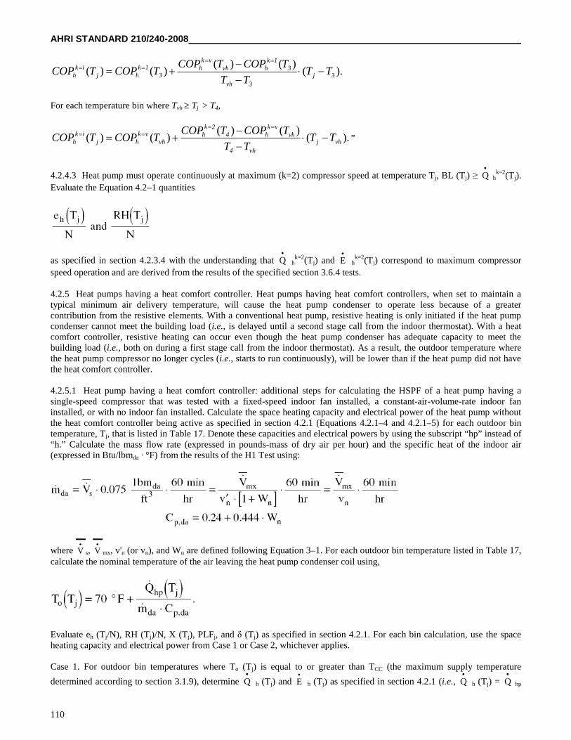
AHRI STANDARD 210/240-2008
110
).()()(
)()( 3j
3vh
31k
hvhvk
h3
1khj
ikh TT
TT
TCOPTCOPTCOPTCOP
For each temperature bin where Tvh Tj > T4,
).()()(
)()( vhj
vh4
vhvk
h42k
hvh
vkhj
ikh TT
TT
TCOPTCOPTCOPTCOP
”
4.2.4.3 Heat pump must operate continuously at maximum (k=2) compressor speed at temperature Tj, BL (Tj) ≥ Q
hk=2(Tj).
Evaluate the Equation 4.2–1 quantities
as specified in section 4.2.3.4 with the understanding that Q
hk=2(Tj) and E
hk=2(Tj) correspond to maximum compressor
speed operation and are derived from the results of the specified section 3.6.4 tests.
4.2.5 Heat pumps having a heat comfort controller. Heat pumps having heat comfort controllers, when set to maintain atypical minimum air delivery temperature, will cause the heat pump condenser to operate less because of a greatercontribution from the resistive elements. With a conventional heat pump, resistive heating is only initiated if the heat pumpcondenser cannot meet the building load (i.e., is delayed until a second stage call from the indoor thermostat). With a heatcomfort controller, resistive heating can occur even though the heat pump condenser has adequate capacity to meet thebuilding load (i.e., both on during a first stage call from the indoor thermostat). As a result, the outdoor temperature wherethe heat pump compressor no longer cycles (i.e., starts to run continuously), will be lower than if the heat pump did not havethe heat comfort controller.
4.2.5.1 Heat pump having a heat comfort controller: additional steps for calculating the HSPF of a heat pump having asingle-speed compressor that was tested with a fixed-speed indoor fan installed, a constant-air-volume-rate indoor faninstalled, or with no indoor fan installed. Calculate the space heating capacity and electrical power of the heat pump withoutthe heat comfort controller being active as specified in section 4.2.1 (Equations 4.2.1–4 and 4.2.1–5) for each outdoor bintemperature, Tj, that is listed in Table 17. Denote these capacities and electrical powers by using the subscript “hp” instead of“h.” Calculate the mass flow rate (expressed in pounds-mass of dry air per hour) and the specific heat of the indoor air(expressed in Btu/lbmda · °F) from the results of the H1 Test using:
where V
s, V
mx, v'n (or vn), and Wn are defined following Equation 3–1. For each outdoor bin temperature listed in Table 17,calculate the nominal temperature of the air leaving the heat pump condenser coil using,
Evaluate eh (Tj/N), RH (Tj)/N, X (Tj), PLFj, and δ (Tj) as specified in section 4.2.1. For each bin calculation, use the spaceheating capacity and electrical power from Case 1 or Case 2, whichever applies.
Case 1. For outdoor bin temperatures where To (Tj) is equal to or greater than TCC (the maximum supply temperature
determined according to section 3.1.9), determine Q
h (Tj) and E
h (Tj) as specified in section 4.2.1 (i.e., Q
h (Tj) = Q
hp
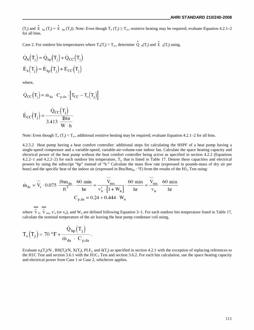
AHRI STANDARD 210/240-2008
111
(Tj) and E
hp (Tj) = E
hp (Tj)). Note: Even though To (Tj) ≥ Tcc, resistive heating may be required; evaluate Equation 4.2.1–2for all bins.
Case 2. For outdoor bin temperatures where To(Tj) > Tcc, determine Q
h(Tj) and E
h(Tj) using,
where,
Note: Even though To (Tj) < Tcc, additional resistive heating may be required; evaluate Equation 4.2.1–2 for all bins.
4.2.5.2 Heat pump having a heat comfort controller: additional steps for calculating the HSPF of a heat pump having asingle-speed compressor and a variable-speed, variable-air-volume-rate indoor fan. Calculate the space heating capacity andelectrical power of the heat pump without the heat comfort controller being active as specified in section 4.2.2 (Equations4.2.2–1 and 4.2.2–2) for each outdoor bin temperature, Tj, that is listed in Table 17. Denote these capacities and electricalpowers by using the subscript “hp” instead of “h.” Calculate the mass flow rate (expressed in pounds-mass of dry air perhour) and the specific heat of the indoor air (expressed in Btu/lbmda · °F) from the results of the H12 Test using:
where V
S, V
mx, v'n (or vn), and Wn are defined following Equation 3–1. For each outdoor bin temperature listed in Table 17,calculate the nominal temperature of the air leaving the heat pump condenser coil using,
Evaluate eh(Tj)/N , RH(Tj)/N, X(Tj), PLFj, and δ(Tj) as specified in section 4.2.1 with the exception of replacing references tothe H1C Test and section 3.6.1 with the H1C1 Test and section 3.6.2. For each bin calculation, use the space heating capacityand electrical power from Case 1 or Case 2, whichever applies.
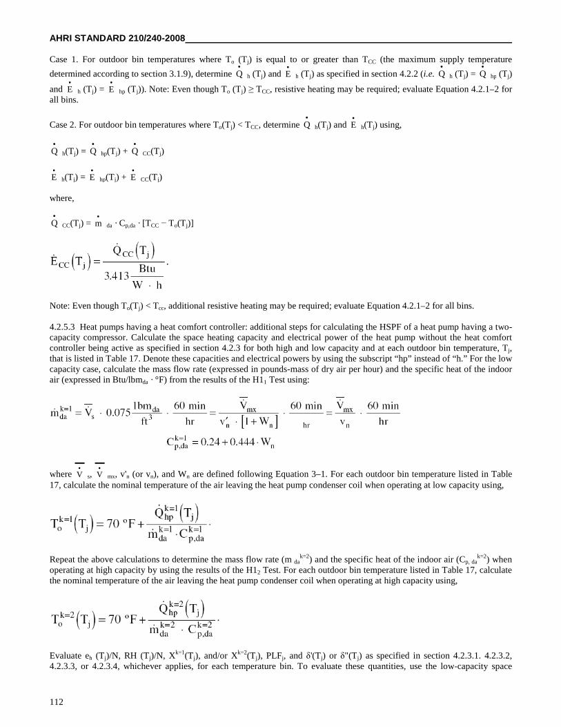
AHRI STANDARD 210/240-2008
112
Case 1. For outdoor bin temperatures where To (Tj) is equal to or greater than TCC (the maximum supply temperature
determined according to section 3.1.9), determine Q
h (Tj) and E
h (Tj) as specified in section 4.2.2 (i.e. Q
h (Tj) = Q
hp (Tj)
and E
h (Tj) = E
hp (Tj)). Note: Even though To (Tj) ≥ TCC, resistive heating may be required; evaluate Equation 4.2.1–2 forall bins.
Case 2. For outdoor bin temperatures where To(Tj) < TCC, determine Q
h(Tj) and E
h(Tj) using,
Q
h(Tj) = Q
hp(Tj) + Q
CC(Tj)
E
h(Tj) = E
hp(Tj) + E
CC(Tj)
where,
Q
CC(Tj) = m
da · Cp,da · [TCC − To(Tj)]
Note: Even though To(Tj) < Tcc, additional resistive heating may be required; evaluate Equation 4.2.1–2 for all bins.
4.2.5.3 Heat pumps having a heat comfort controller: additional steps for calculating the HSPF of a heat pump having a two-capacity compressor. Calculate the space heating capacity and electrical power of the heat pump without the heat comfortcontroller being active as specified in section 4.2.3 for both high and low capacity and at each outdoor bin temperature, Tj,that is listed in Table 17. Denote these capacities and electrical powers by using the subscript “hp” instead of “h.” For the lowcapacity case, calculate the mass flow rate (expressed in pounds-mass of dry air per hour) and the specific heat of the indoorair (expressed in Btu/lbmda · °F) from the results of the H11 Test using:
where V
s, V
mx, v'n (or vn), and Wn are defined following Equation 3–1. For each outdoor bin temperature listed in Table17, calculate the nominal temperature of the air leaving the heat pump condenser coil when operating at low capacity using,
Repeat the above calculations to determine the mass flow rate (m dak=2) and the specific heat of the indoor air (Cp, da
k=2) whenoperating at high capacity by using the results of the H12 Test. For each outdoor bin temperature listed in Table 17, calculatethe nominal temperature of the air leaving the heat pump condenser coil when operating at high capacity using,
Evaluate eh (Tj)/N, RH (Tj)/N, Xk=1(Tj), and/or Xk=2(Tj), PLFj, and δ'(Tj) or δ"(Tj) as specified in section 4.2.3.1. 4.2.3.2,4.2.3.3, or 4.2.3.4, whichever applies, for each temperature bin. To evaluate these quantities, use the low-capacity space
AHRI STANDARD 210/240-2008
113
heating capacity and the low-capacity electrical power from Case 1 or Case 2, whichever applies; use the high-capacity spaceheating capacity and the high-capacity electrical power from Case 3 or Case 4, whichever applies.
Case 1. For outdoor bin temperatures where Tok=1(Tj) is equal to or greater than TCC (the maximum supply temperature
determined according to section 3.1.9), determine Q
hk=1(Tj) and E
hk=1(Tj) as specified in section 4.2.3 (i.e., Q
hk=1(Tj) = Q
hpk=1(Tj) and E
hk=1(Tj) = E
hpk=1(Tj).
Note: Even though Tok=1(Tj) ≥ TCC, resistive heating may be required; evaluate RH (Tj)/N for all bins.
Case 2. For outdoor bin temperatures where Tok=1(Tj) < TCC, determine Q
hk=1(Tj) and E
hk=1(Tj) using,
Q
hk=1(Tj) = Q
hpk=1(Tj) + Q
CCk=1(Tj)
E
hk=1(Tj) = E
hpk=1(Tj) + E
CCk=1(Tj)
where,
Note: Even though Tok=1(Tj) ≥ Tcc, additional resistive heating may be required; evaluate RH (Tj)/N for all bins.
Case 3. For outdoor bin temperatures where Tok=2(Tj) is equal to or greater than TCC, determine Q
hk=2(Tj) and E
hk=2(Tj) as
specified in section 4.2.3 (i.e., Q
hk=2(Tj) = Q
hpk=2(Tj) and E
hk=2(Tj) = E
hpk=2(Tj)). Note: Even though To
k=2(Tj) < TCC,
resistive heating may be required; evaluate RH (Tj)/N for all bins.
Case 4. For outdoor bin temperatures where Tok=2(Tj) < TCC, determine Q
hk=2(Tj) and E
hk=2(Tj) using,
where,
Note: Even though Tok=2(Tj) < Tcc, additional resistive heating may be required; evaluate RH (Tj)/N for all bins.
AHRI STANDARD 210/240-2008
114
4.2.5.4 Heat pumps having a heat comfort controller: additional steps for calculating the HSPF of a heat pump having avariable-speed compressor. [Reserved]
4. Calculations of the Actual and Representative Regional Annual Performance Factors for Heat Pumps.
4.3.1 Calculation of actual regional annual performance factors (APFA) for a particular location and for each standardizeddesign heating requirement.
where,
CLHA = the actual cooling hours for a particular location as determined using the map given in Figure 3, hr.
Q
ck(95) = the space cooling capacity of the unit as determined from the A or A2 Test, whichever applies, Btu/h.
HLHA = the actual heating hours for a particular location as determined using the map given in Figure 2, hr.
DHR = the design heating requirement used in determining the HSPF; refer to section 4.2 and Definition 1.22, Btu/h.
C = defined in section 4.2 following Equation 4.2–2, dimensionless.
SEER = the seasonal energy efficiency ratio calculated as specified in section 4.1, Btu/W·h.
HSPF = the heating seasonal performance factor calculated as specified in section 4.2 for the generalized climatic region thatincludes the particular location of interest (see Figure 2), Btu/W·h. The HSPF should correspond to the actual design heatingrequirement (DHR), if known. If it does not, it may correspond to one of the standardized design heating requirementsreferenced in section 4.2.
4.3.2 Calculation of representative regional annual performance factors (APFR) for each generalized climatic region and foreach standardized design heating requirement.
where,
CLHR = the representative cooling hours for each generalized climatic region, Table 19, hr.
HLHR = the representative heating hours for each generalized climatic region, Table 19, hr.
HSPF = the heating seasonal performance factor calculated as specified in section 4.2 for the each generalized climatic regionand for each standardized design heating requirement within each region, Btu/W·h.
The SEER, Q
ck (95), DHR, and C are the same quantities as defined in section 4.3.1. Figure 2 shows the generalized
climatic regions. Table 18 lists standardized design heating requirements.
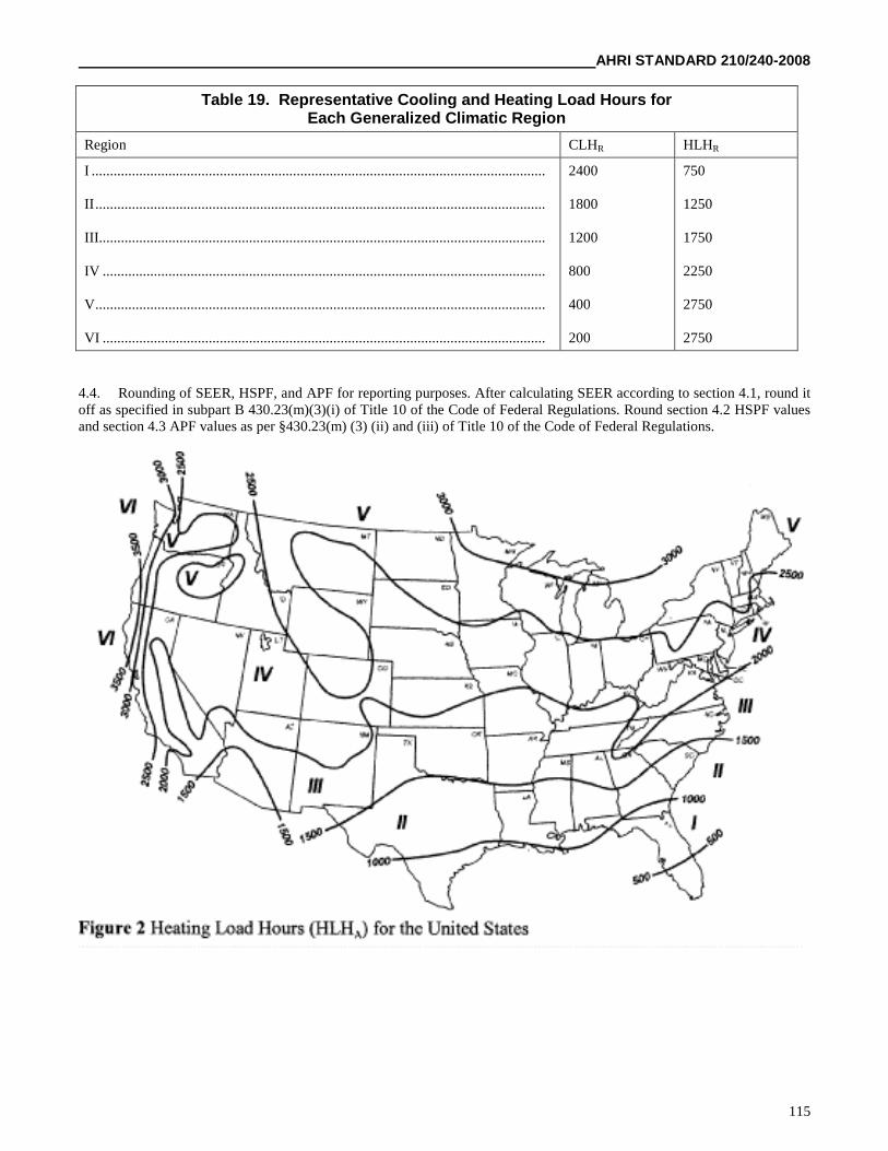
AHRI STANDARD 210/240-2008
115
Table 19. Representative Cooling and Heating Load Hours forEach Generalized Climatic Region
Region CLHR HLHR
I ............................................................................................................................
II...........................................................................................................................
III..........................................................................................................................
IV .........................................................................................................................
V...........................................................................................................................
VI .........................................................................................................................
2400
1800
1200
800
400
200
750
1250
1750
2250
2750
2750
4.4. Rounding of SEER, HSPF, and APF for reporting purposes. After calculating SEER according to section 4.1, round itoff as specified in subpart B 430.23(m)(3)(i) of Title 10 of the Code of Federal Regulations. Round section 4.2 HSPF valuesand section 4.3 APF values as per §430.23(m) (3) (ii) and (iii) of Title 10 of the Code of Federal Regulations.
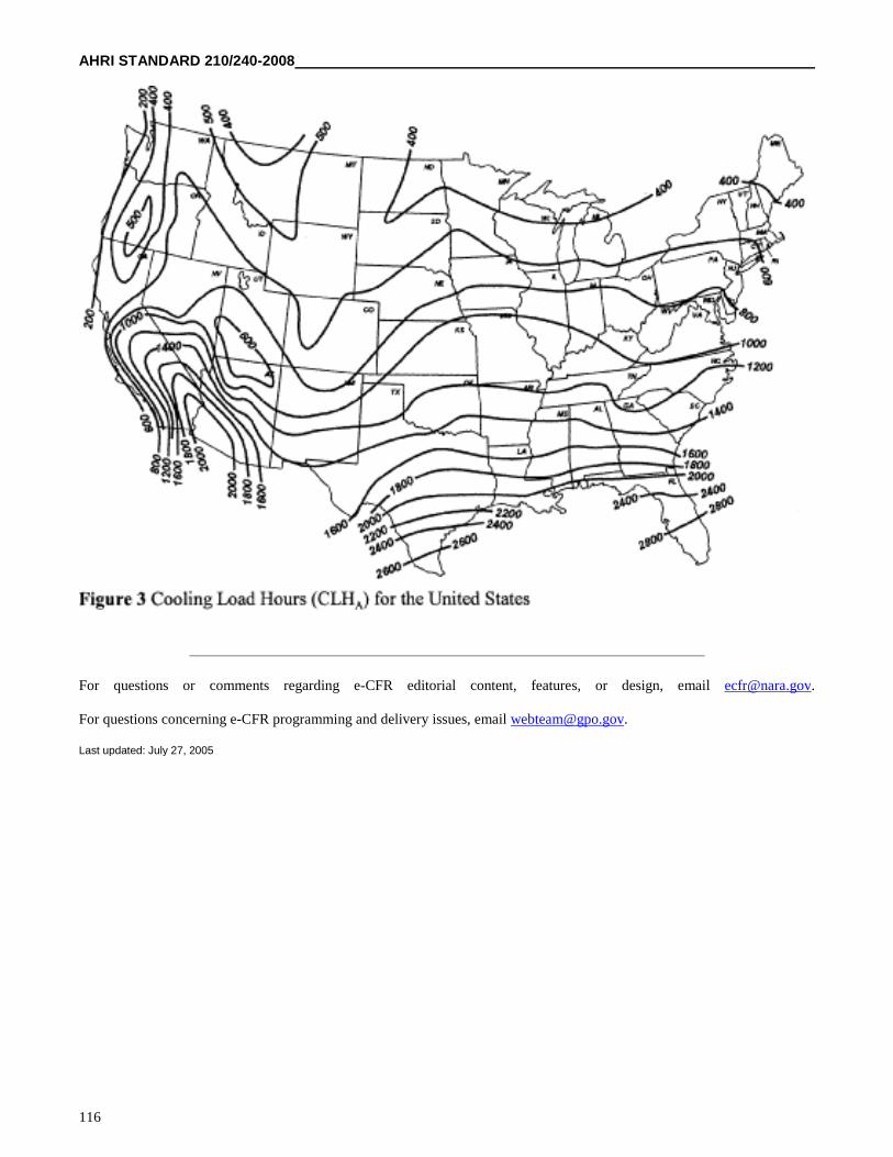
AHRI STANDARD 210/240-2008
116
For questions or comments regarding e-CFR editorial content, features, or design, email [email protected].
For questions concerning e-CFR programming and delivery issues, email [email protected].
Last updated: July 27, 2005
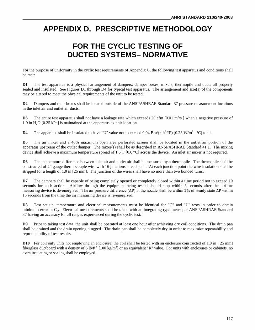
AHRI STANDARD 210/240-2008
117
APPENDIX D. PRESCRIPTIVE METHODOLOGY
FOR THE CYCLIC TESTING OFDUCTED SYSTEMS– NORMATIVE
For the purpose of uniformity in the cyclic test requirements of Appendix C, the following test apparatus and conditions shallbe met:
D1 The test apparatus is a physical arrangement of dampers, damper boxes, mixers, thermopile and ducts all properlysealed and insulated. See Figures D1 through D4 for typical test apparatus. The arrangement and size(s) of the componentsmay be altered to meet the physical requirements of the unit to be tested.
D2 Dampers and their boxes shall be located outside of the ANSI/ASHRAE Standard 37 pressure measurement locationsin the inlet air and outlet air ducts.
D3 The entire test apparatus shall not have a leakage rate which exceeds 20 cfm [0.01 m3/s ] when a negative pressure of1.0 in H2O [0.25 kPa] is maintained at the apparatus exit air location.
D4 The apparatus shall be insulated to have "U" value not to exceed 0.04 Btu/(hft2F) [0.23 W/m2 · °C] total.
D5 The air mixer and a 40% maximum open area perforated screen shall be located in the outlet air portion of theapparatus upstream of the outlet damper. The mixer(s) shall be as described in ANSI/ASHRAE Standard 41.1. The mixingdevice shall achieve a maximum temperature spread of 1.5F [0.8 C] across the device. An inlet air mixer is not required.
D6 The temperature difference between inlet air and outlet air shall be measured by a thermopile. The thermopile shall beconstructed of 24 gauge thermocouple wire with 16 junctions at each end. At each junction point the wire insulation shall bestripped for a length of 1.0 in [25 mm]. The junction of the wires shall have no more than two bonded turns.
D7 The dampers shall be capable of being completely opened or completely closed within a time period not to exceed 10seconds for each action. Airflow through the equipment being tested should stop within 3 seconds after the airflowmeasuring device is de-energized. The air pressure difference (ΔP) at the nozzle shall be within 2% of steady state ΔP within 15 seconds from the time the air measuring device is re-energized.
D8 Test set up, temperature and electrical measurements must be identical for "C" and "U" tests in order to obtainminimum error in CD. Electrical measurements shall be taken with an integrating type meter per ANSI/ASHRAE Standard37 having an accuracy for all ranges experienced during the cyclic test.
D9 Prior to taking test data, the unit shall be operated at least one hour after achieving dry coil conditions. The drain panshall be drained and the drain opening plugged. The drain pan shall be completely dry in order to maximize repeatability andreproducibility of test results.
D10 For coil only units not employing an enclosure, the coil shall be tested with an enclosure constructed of 1.0 in [25 mm]fiberglass ductboard with a density of 6 lb/ft3 [100 kg/m3] or an equivalent "R" value. For units with enclosures or cabinets, noextra insulating or sealing shall be employed.
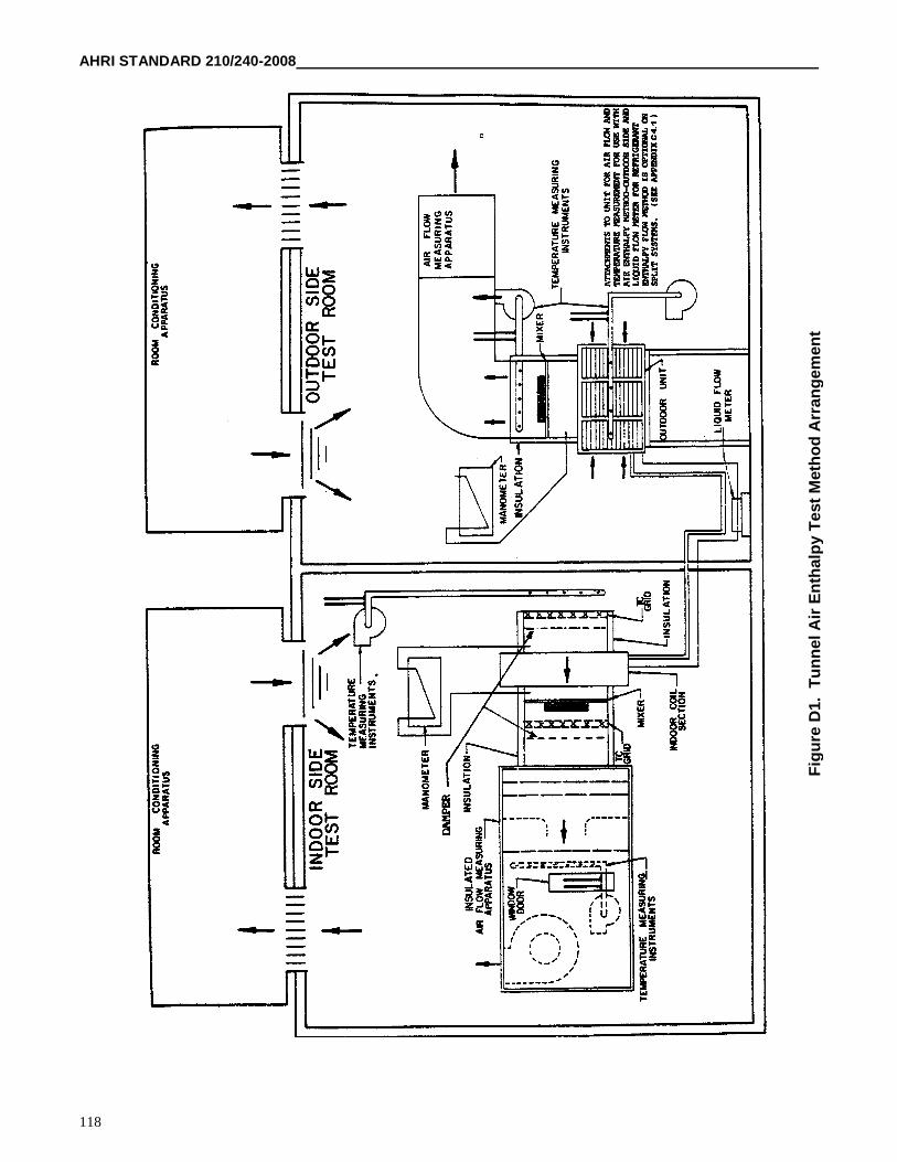
AHRI STANDARD 210/240-2008
118
Fig
ure
D1.
Tu
nn
elA
irE
nth
alp
yT
est
Meth
od
Arr
an
gem
en
t
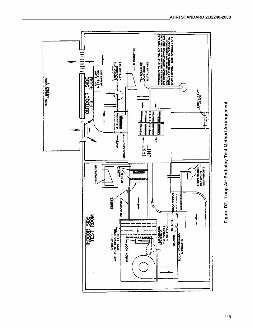
AHRI STANDARD 210/240-2008
119
Fig
ure
D2.
Lo
op
Air
En
thalp
yT
est
Meth
od
Arr
an
gem
en
t
AHRI STANDARD 210/240-2008
120
Fig
ure
D3.
Calo
rim
ete
rA
irE
nth
alp
yT
est
Meth
od
Arr
an
gem
en
t
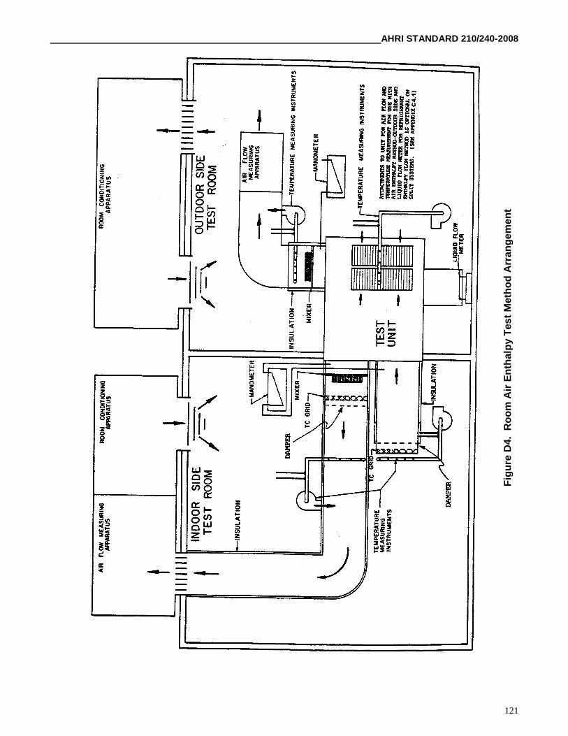
AHRI STANDARD 210/240-2008
121
Fig
ure
D4.
Ro
om
Air
En
thalp
yT
est
Meth
od
Arr
an
gem
en
t
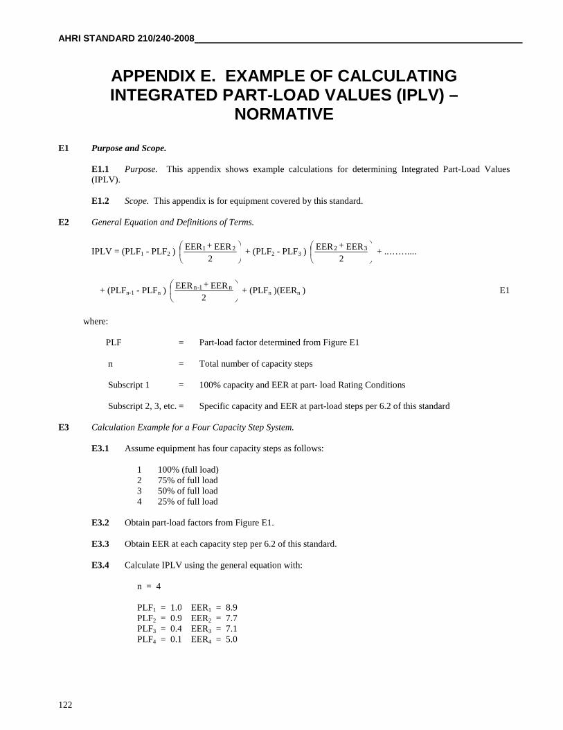
AHRI STANDARD 210/240-2008
122
APPENDIX E. EXAMPLE OF CALCULATINGINTEGRATED PART-LOAD VALUES (IPLV) –
NORMATIVE
E1 Purpose and Scope.
E1.1 Purpose. This appendix shows example calculations for determining Integrated Part-Load Values(IPLV).
E1.2 Scope. This appendix is for equipment covered by this standard.
E2 General Equation and Definitions of Terms.
IPLV = (PLF1 - PLF2 )
2
EEREER 21++ (PLF2 - PLF3 )
2
EEREER 32 ++ ..……....
+ (PLFn-1 - PLFn )
2
EEREER n1-n ++ (PLFn )(EERn ) E1
where:
PLF = Part-load factor determined from Figure E1
n = Total number of capacity steps
Subscript 1 = 100% capacity and EER at part- load Rating Conditions
Subscript 2, 3, etc. = Specific capacity and EER at part-load steps per 6.2 of this standard
E3 Calculation Example for a Four Capacity Step System.
E3.1 Assume equipment has four capacity steps as follows:
1 100% (full load)2 75% of full load3 50% of full load4 25% of full load
E3.2 Obtain part-load factors from Figure E1.
E3.3 Obtain EER at each capacity step per 6.2 of this standard.
E3.4 Calculate IPLV using the general equation with:
n = 4
PLF1 = 1.0 EER1 = 8.9PLF2 = 0.9 EER2 = 7.7PLF3 = 0.4 EER3 = 7.1PLF4 = 0.1 EER4 = 5.0
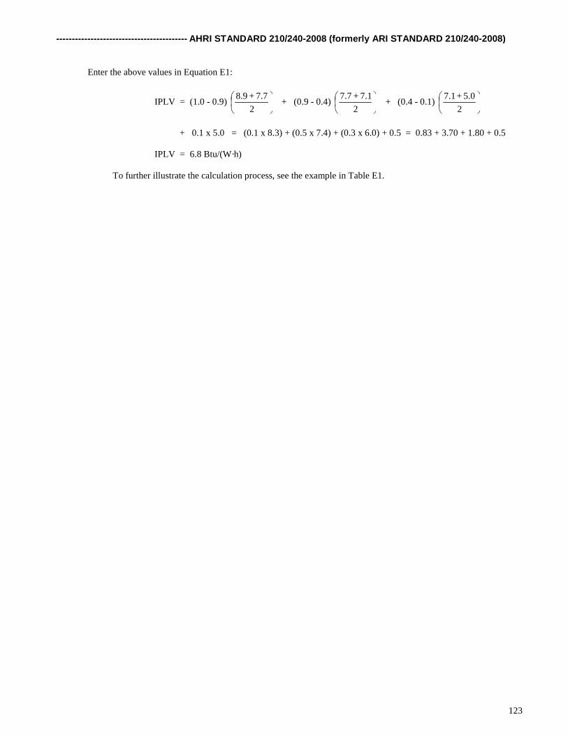
------------------------------------------ AHRI STANDARD 210/240-2008 (formerly ARI STANDARD 210/240-2008)
123
Enter the above values in Equation E1:
IPLV = (1.0 - 0.9)
2
7.7+8.9+ (0.9 - 0.4)
2
7.1+7.7+ (0.4 - 0.1)
2
5.0+7.1
+ 0.1 x 5.0 = (0.1 x 8.3) + (0.5 x 7.4) + (0.3 x 6.0) + 0.5 = 0.83 + 3.70 + 1.80 + 0.5
IPLV = 6.8 Btu/(W·h)
To further illustrate the calculation process, see the example in Table E1.
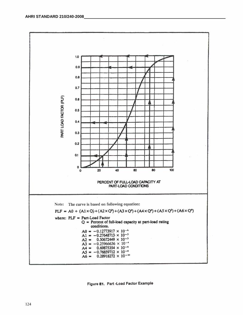
AHRI STANDARD 210/240-2008
124
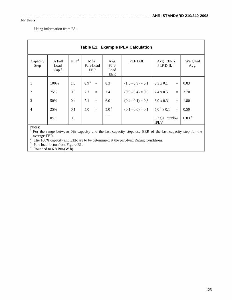
------------------------------------------------------------------------------------------------------ AHRI STANDARD 210/240-2008
125
I-P Units
Using information from E3:
Table E1. Example IPLV Calculation
CapacityStep
% FullLoadCap.2
PLF3 Mfrs.Part-Load
EER
Avg.Part-LoadEER
PLF Diff. Avg. EER xPLF Diff. =
WeightedAvg.
1
2
3
4
100%
75%
50%
25%
0%
1.0
0.9
0.4
0.1
0.0
8.9 2 =
7.7 =
7.1 =
5.0 =
8.3
7.4
6.0
5.0 1
-----
(1.0 - 0.9) = 0.1
(0.9 - 0.4) = 0.5
(0.4 - 0.1) = 0.3
(0.1 - 0.0) = 0.1
8.3 x 0.1 =
7.4 x 0.5 =
6.0 x 0.3 =
5.0 1 x 0.1 =
Single numberIPLV
0.83
3.70
1.80
0.50
6.83 4
Notes:1 For the range between 0% capacity and the last capacity step, use EER of the last capacity step for the
average EER.2 The 100% capacity and EER are to be determined at the part-load Rating Conditions.3 Part-load factor from Figure E1.4 Rounded to 6.8 Btu/(W·h).
Top Related