


Languages
Pages
Legal


I<6 7
�' - ' ' f-- V'11L4i . . -
. A. . i
ATOMIC ENERGY OF CANADA LIMITED
AECL--6 4 4 0
DE82 902004
AN ASSESSMENT OF MATERIALS FOR
NUCLEAR FUEL IMMOBILIZATION CONTAINERS
by
K. Nuttall and V.F. Urbanic*
* System Materials Branch,Chalk River Nuclear Laboratories
Whiteshell Nuclear Research Establishment
l Pinawa, Manitoba ROE iLO,I, 1981 September
AECL-6440
ia-d ED~~aJ~~A L ;.V 'L -~-
"FT"e"IM77" -1--- = a

AN ASSESSMENT OF MATERIALS FOR
NUCLEAR FUEL IMMOBILIZATION CONTAINERS
by
K. Nuttall and V.F. Urbanic
ABSTRACT
A wide range of engineering metals ane alloys has been assessedfor their suitability as container materials for irradiated n.clear fuelintended for-permanent disposal in a deep, underground hard-rock vault.The expected range of service conditions in the disposal vault arediscussed, as well as the material properties required for this applica-tion. An important requirement is that the container last at least500 years without being breached. The assessment is treated in twoparts. Part-I concentrates on the physical and mechanical metallurgy,with special reference to strength, weldability, potential embrittlementmechanisms and some economic aspects. Part II discusses possible mech-anisms of metallic corros-on for the various engineering alloys and theexpected range of environmental conditions in the vault. Localizedcorrosion and delayed fracture processes are identified as being mostlikely to limit container lifetime. Hence an essential requirement isthat such processes either be absent or proceed at an insignificantrate.
Three groups of alloys are recommended for further consider-'ation as possible container materials: AISI 300 series austeniticstainless steels, high nickel-base alloys and very dilute titanium-basealloys. Specific alloys from each group are indicated as having theoptimum combination of required properties, including cost. For con-tainer designs where the outer container shell does not independently;,support the service loads,- copper should also be considered. The finalmaterial selection will depend primarily on the environmental conditionsin the vault.- -Some recommendations are given for future research on thecandidate materials -:
-.. SUPS::. O. ;_:: . :- . .; , 27Atomic Energy of Canada Limited
'c Whiteshell. Nuclear Research Fstablishment 2 cG. 2 -; Pinawa, Manitoba RtOE lLO
C.2 - :- 1981 September6.. -. ;C ,,.. . , . -,i .-- ,
i AECL-6440
= I 10111 11 I I

UNE EVALUATION DES MATERIAUX POUR CONTENEURS DESTINES
A L'IMMOBILISATION DU COMBUSTIBLE NUCLEAIRE
par
K. Nuttall et V.F. Urbanic
RESUME
On a evalue une grande variete de metaux et d'alliages indus-triels du point de vue de leurs possibilites d'utilisation comme mate-riaux pour conteneurs de combustible nucleaire irradie destines a l'eva-cuation permanente dans ue enceinte situee a grande profondeur dans laroche dure'. On examine les diverses conditions de service pr6vues dansl'enceinte d'evacuation de meme que les proprietes des materiaux n6ces-saires pour cette application. Une condition importante est que le'conteneur'doit durer 500 ans sans se rompre. On traite l'valuation endeux parties. La premiere partie porte surtout sur la m6tallurgie -physique "t mecanique et traite particulierement de la resistance, de lapossibilite de soudage, des m6canismes de fragilisation possibles ot dccertains aspects economiques. La deuxieme partie traite des m6canismespossibles-de corrosion metallique de divers alliages industriels et desdiverses conditions prevues dans lc milieu de 1tenceinte. On considereles processus de corrosion localis6s et de fissuration retardes commeetant les plus tusceptibles de limiter la duree de vie des conteneurs.-La condition essentielle est donc que ces processus ne se produisent pasdu tout ou qu'ils sc produisent a Lte vitesse negligeable.
On recommande 16tude poussee de trois groupes d'alliagescomme materiaux 'possibles de conteneurs: la serie AIST 300 d'aciersinoxydables austenitiques, les alliages a teneur elevee en nickel et lesalliages au titanium tres dilue. On indique que les alliages particu-liers de chaque groupe possedent la combinaison optimale de proprietesnecessaires ain-siU que le cout'. On pourrait considerer aussi le cuivrepour les types 'de'conteneurs dont l'enveloppe ext6rieure nia pas asupporter elle-m4nml des charges en service. Le choix final du materieldependra surtout des conditions existant dans le milieu de 1'enceinte.On donne queigues conseils pour les recherches futures sur les materiauxpossibles.
~~t .1 W: A......- .. .,
L'Energie Atomique du Canada Limit~eEtablissement.'de Recherches Nucleaires de Whiteshell
'; Pinawa, Manitoba ROE lLO-1981 septembre
AECL-6440
� W 11 I 11�1101111 I - P

Ii
CONTENTS
Page
1. INTRODUCTION 1
2. GUIDELINES FOR MATERIAL SELECTION 4
PART I-- PHYSICAL AND MECHANICAL METALLURGY 7
3. LOW-MELTING-POINT ALLOYS 7
3.1 ALUMINUM-BASE ALLOYS 73.2 MAGNESIUM-BASE ALLOYS 10
4. PLAIN CARBON AND LOW-ALLOY STEELS 11
5. STAINLESS STEELS 13
5.1 FERRITIC STAINLESS STEELS 135.1.1 Welding 145.1.2 Embrittlement Effects 145.1.3 Corrosion 185.1.4 Recent Developments 18
5.2 AUSTENITIC (y) STAINLESS STEELS (WROUGHT) 195.2.1 Constitution 195.2.2 Welding and Weld Decay 205.2.3 Embrittlement Effects 23
5.3 MARTENSITIC STAINLESS STEELS 255.4 PRECIPITATION HARDENING (PH) STAINLESS STEELS 26
6. SUPERALLOYS AND HIGH-ALLOY AUSTENITICS 27
6.1 WELDAPILITY 296.2 EMBRITTLEMENT EFFECTS 30
6.2.1 Sigma Phase 306.2.2 Transgranular Stress Corrosion Cracking 306.2.3 intergranular Stress Corrosion Cracking 31
... /cont.
lEE

CONTENTS, continued
Page
7. TITANIUM AND TITANIUM ALLOYS 33
7.1 WELDABILITY 35
7.2 CORROSION 37
7.3 EMBRITTLEMENT EFFECTS 37
7.3.1 Stress Corrosion Cracking 37
7.3.2 Hydrogen Embrittlement and DelayedFracture 40
8. -. .COPPER AND COPPER ALLOYS 48
,8.1 PURE COPPER AND HIGH COPPER ALLOYS 49
8.2- BRASSES 51
8.3 BRONZES -., 51
'.3.1 LTin Bronzes 51'8.3.2 Aluminum Bronzes - 52
, 8.3.3 Silicon Bronzes - 53
8.4: COPPER-NICKEL ALLOYS 53
8.5>- WELDABILITY 54
8.6: CORROSION 56
8.7. EMBRITTLEMENT EFFECTS 57
8.7.1 Stress Corrosion Cracking 57
9. COST AND DESIGN ASPECTS 57
s.- -9.1; MATERIALS PROPERTY SPECIFICATIONS 57
9.2 MATERIAL COSTS 58
i-9.3,, FABRICATED MATERIAL 609.4 ,AVAILABILITY. .R 61
9.5 CLADDING- .- 62
10. 1 -. SUMMARY OF PART I -, :. 63
-;tsA
.I..cont.
I q I 111111 N��l W�� -

CONTENTS, continued
Page
PART II - CORROSION 70
11. INTRODUCTION 70
12. CORROSION OF METALS 71
12.1 GENERAL INTRODUCTION12.2 GENERAL PRINCIPLES 7212.3 ENVIRONMENTAL EFFECTS 7512.4 TYPES OF CORROSION 77
12.4.1 Uniform Corrosion (or GeneralAttack) 79
12.4.2 Crevice Corrosion 7812.4.3 Pitting 7912.4.4 Intergranular Corrosion 8212.4.5 Stress Corrosion Cracking 8412.4.6 Galvanic Corrosion 8512.4.7 Erosion Corrosion 8512.4.8 Selective Leaching 85
13. GROUNDWATER CHEMISTRY 86
14. SELECTION OF CANDIDATE MATERIALS 88
14.1 ALUMINUM- AND MAGNESIUM-BASE ALLOYS 8914.1.1 Aluminum and Aluminum-Base Alloys 8914.1.2 Magnesium and Magnesium-Base Alloys 91
14.2 PLAIN CARBON AND LOW-ALLOY FERRITIC STEELS 9214.3 STAINLESS STEELS 9414.4 SUPERALLOYS AND HIGH-ALLOY AUSTENITICS 9914.5 TITANIUM AND TITANIUM ALLOYS 10214.6 COPPER AND COPPER ALLOYS 107
15. SIbMNMARY OF PART II 111
..../cont.

CONTENTS, concl uded
Page
16. CONCLUSIONS116
ACKNOWLEDGEMENTS 118
REFMREN' -S1-E . : : . ': . ... - - . - ~~~~~119
C V' . . 7: ( : :- - .
TABLES
FIGURES166
s n . ,, - --
*~~~~~ ~ - S, -
, ....T-, ,I . C .) . -,*-

II
1. INTRODUCTION
As part of the Canadian program for the safe management and
disposal of radioactive fuel wastes from CANDU* nuclear reactors, a
study is being made of the immobilization and disposal of irradiated(1,2)
fuel bundles in a stable, deep, hard-rock vault . If, after a
comprehensive assessment phase, the disposal concept is considered to be
valid, the overall program calls for the construction of a demonstration
vault in which .Ltive experiments will be monitored as part of the
evaluation of the complete facility. Ultimately, an industrial-scale
vault for the permanent disposal of irradiated fuel is planned. One of
the active experiments in the demonstration vault will involve emplacing
a quantity of radioactive fuel isolated from the host environment by
specially engineered containers(2)
The approach being used in the Canadian Nuclear Fuel Waste
Management Program is closely similar to that adopted by several other
countries( ). For example, the Swedish nuclear power utilities, in
response to government legislation, organized a joint project (the KBS**
project) to develop and assess concepts to safely immobilize and dispose
of irradiated fuel and vitrified high-level waste. They recommended
that final disposal should be in igneous rock at a depth of about 500 m.
Their proposals for immobilization are as follows(3)
- Encapsulate irradiated fuel in copper containers having a wall
thickness of 200 mm and invest lead around the fuel.
- Encapsulate vitrified high-level waste in a titanium outer
container, of wall thickness 6 mm, which is lined with high-
purity lead 100 mm thick.
* CANDU E CANada Deuterium Uranium
** KBS -- Kgrnbrgnslesgkerhet = Nuclear Fuel Safety

-2-
Due to time constraints, however, these proposals were not optimized in
terms of container design and fabrication.
The objective of the present assessment is to select a short
list of candidate container materials for a relatively simple contain-
ment system to be emplaced during the demonstration phase of the pro-
gram, but with the future option of permanent disposal. Thus, the
containers should be capable of retrieval for at least the duration of
the demonstration. A container design life of at least 500 years before
perforation 'as been selected during which time the fission product
axtivity of tone fuel will decay substantially( ). The following assump-
tiors concerning the conditions in the hard-rock vault will also be
taken :nto L-zcoant in the material selection and container design:
1. Ths --ntainer tempe .ture will be 150'C or less.
2. GSouZndq,..L'!r will contact the container (a brief discussion of
groundwater composition is given in Part II of this report).
3. The vault may be expected to flood to its depth below the
surface (500 - 1000 m), creating a hydrostatic pressure which
the container must withstand without being breached.
As an initial approach, a simple, cylindrical metal container
is-beting considered. -Sinc'e the container must by definition be leak-
tight, end closures will be joined to the cylindrical body by welding.
;The materials selected in this assessment may be used to fabricate and
test, a- -number of prototype containers.
1; *. - -;-.Two basic concepts for the design of a simple container are
being examined, both of which use a cylindrical shell of large diameter
(300 - 900 mm). In the stressed-shell concept, the container itself is
designed to independently support the stresses imposed by fabrication,
'i'; t :;
S ZJ C' C.
Sr e(
iflvc
.':'

- 3 -
handling and subsequent service in the disposal vault. This will
necessitate a fairly large wall thickness, in the range 10 - 50 mm,
depending on the material, container diameter and vault depth. In the
supported-shell concept, the design is such that the externally imposed
hydrostatic stresses on the container will be supported by an internal
medium. A number of options for the supporting medium are being studied,
such as:
1. investment with a fairly low-melting-point metal, e.g., lead,
zinc, aluminum, or Lheir alloys;
2. packing with a particulate material, e.g., sand, glass beads;
3. fabrication of internal periodic, rigid bracing.
Thus the wall thickness of a supported-shell container can be apprecia-
bly smaller than that of a stressed-shell container and, in the absence
of other criteria, would be determined primarily by the handling stresses
and required corrosion allowance. The final design of a fuel immobili-
zation container for the demonstration and commercial vaults will be
based, at least in part, on the present materials assessment, future
laboratory studies, and the container fabrication and testing program.
In the following section, 3imple guidelines for material
selection are proposed. They attempt to take into account the special-
ized application of the material (containment of radioactive fuel), the
specific type of disposal environment (hardrock vault at a depth of
500 - 1000 m)(2) and the remote-handling procedures likely to be
involved in the container fabrication.
-4-
2. GUIDELINES FOR MATERIAL SELECTION
Ideally, the material chosen should conform to the following
guidelines:
1. The simplest matrix microstructure consistent with other
requirements, i.e., a single-phase pure metal or solid-solu-
tion alloy, so that complicating effects due to precipitation
hardening, tempering treatments, etc. aze not deliberately
introduced into the fabrication process.
2. A stable microstructure, to avoid adverse metallurgical changes
during long periods at low temperature.
3. Adequate short-term strength and impact resistance, to support
the fuel and to withstand handling and accidental impact
loading. The container must resist buckling, collapse and/or
excessive creep under the hydrostatic pressure attained if the
vault floods (9.8 MPa at a depth of 1000 m). There is likely
to be some flexibility here for selecting different materials
with different strengths to give a range of container thick-
nesses with the same specific strength.
4. Good weldability with, preferably, no requirement for pre- or
post-weld heat treatment.
5. Acceptable toughness and cracking resistance in the parent and
weld metal, to resist fracture generally, and also that due to
delayed fracture mechanisms, such as stress corrosion cracking
and hydrogen embrittlement.
6. Acceptably low rates of uniform corrosion and immunity to
localized corrosion, e.g., pitting and crevice corrosion, in
the vault environment.
I':
-5-
7. Preferably an established background of knowledge and ex-
perience.
8. Reasonable assurance of an adequate supply at acceptable cost.
The range of commercially available metals and alloys used for
structural and containment applications can be categorized as:
1. Low-melting-point alloys, e.g., aluminum-base, magnesium-base.
2. Plain carbon and low-alloy ferritic steels.
3. Stainless steels:
- ferritic
- austenitic
- martensitic
- precipitation hardening
- austenitic/ferritic
4. Superalloys and high-alloy austenitics:
- nickel-copper
- nickel-chromium
- iron-nickel-chromium
- Monels
- Inconels, Hastelloys
Nimonics
- Incoloys
5. Commercially pure titanium arnd its alloys.
6. Commercially pure copper and its alloys.
The above list is not exhaustive and does not include the re-
fractory metals, for example, or zirconium and its alloys.
This study considers the important properties of the alloy
groups above, either in general or with special reference to the more
likely specific alloys within a group. Part I discusses some of the

-.6 -
physical metallurgy aspects of the alloy groups, particularly as they
affect mechanical properties, weldability, delayed fracture processes
and, to some extent, metallurgical compatibility. Since corrosion
behaviour is clearly of prime importance for this application, it is
discussed separately in some detail in Part II.
Since this review attempts to cover the broad spectrum of
available engineering metals and alloys, it was necessary to adopt a
selective approach in order to limit its size. This was achieved by
placing greater emphasis on those aspects of the properties and behav-
iour of a material t0-t are both controversial and perceived to be a
potential limiting factor in the fabrication and performance of con-
tainers.for fuelimmobilization. Conversely, those aspects of proper-
ties and behaviour that are non-controversial and understood and will
nbt, in themselves, lidit the container-integrity, are considered in
less depth.. . . - . .
Some overlap exists in Parts I and II in some specific areas,
e;.g., stress corrosion cracking, which-has both a mechanical and envi-
ronmental component. In these cases, Part I emphasizes the physical
metallurgy and fracture toughness aspects whilst Part II concentrates
more on electrochemical factors. . -
a: .. -T. .. ::- .: -
//.; ~~~~~~- f .- .,- -t.... -~ - .>.-- ; ;A ,a;-... :-
a'1 -ai
iiCe_.:..:
i- _ ' ~~~~~~. ii,:t.i. d :-ea:g: ,i)_
?'e;a Em- ;-o-?_v-.'. 1s.,'.: i .'; i.A: .
alcE -.- a-- a of v; >'.-: s 'pi .- ' I: ''_' ' P .. ,.: .;-':t..i Oft;.. .; _-:
- 7 -
PART i - PHYSICAL AND MECHANIC.Al METALLURGY
3. LOW-MELTING-POINT ALLOYS
3.1 ALUMINUM-BASE ALLOYS
Wrought aluminum-base alloys are basically divided into two
groups namely, heat-treatable (H.T.) and non-heat-treatable. Most
alloys are designated according to the Aluminum Association series(4)
shown in Table 1, which indicates the major alloying additions and the(4-6)
amenability of the alloy series to heat treatment The 4000 series
alloys have a rather specialized use and are not regarded as structural
materials.
The strength properties of the pure aluminum and non-heat-
treatable alloys are developed by strain hardening (cold working), and
by alloying additions which promote either solid solution or second-
phase dispersion strengthening. In the 3000 series alloys, manganese
additions produce dispersed precipitates, whereas in the 5000 series
magnesium in solution is the main strengthening agent.
In the heat-treatable aluminum alloys, the alloying additions
are retained in solid solution by quenching from an elevated temperature
(solution heat treating). Strengthening is then effected by precipi-
tating a portion of the soluble elements in a finely divided form
during an age-hardening heat treatment.
The range of strength and ductility which can be developed in
some cnmmonly used alloys is shown in Table 2. For the non-heat-treat-
able alloys, the thickness requirements place a practical limit on the
strengthening that can be achieved by cold working. Thus, for thick-
nesses i the range 15-50 mm, the highest minimum yield strengths

- 8 -
are generally < 210 MPa. Moreover, the ductility in these high-strength
t:,conditions can be fairly low (a\ 5%). Appreciably higher minimum yield
strengths can be developed in the heat.-treatable alloys, without thick-
ness limitations, although the ductility in the high-strength conditions
is again low. In the annealed condition, tle yield strength of all the
aluminum alloys is quite low, typically 28-140 MPa. Moreover, being
a-;- low-melting-point alloys, the strength in any condition decreases
markedly with increase in temperature, and, at 150%C, the yield stress
-) of the non-heat-treatable alloys (even in the fully cold-worked temper)
and of most of the heat-treatable alloys, is less than 210 MPa( ).
With extended service at Xv 150'C, the yield stress of all
'alloys would be expected to decrease progressively due to overageing in
cc~ cthe heat-treatable alloys and recovery processes in the cold-worked(6).
l I;--a'lloys . Typical age-hardening temperatures for aluminum-base alloys
- are 100--- 1750C, which embraces the possible service temperature of the
container. Thus, unless very heavy section thickness are used, con-
*; -i rter-bt>:kling due to creep is likely to occur under the hydrostatic
-- pressure developed in the event of flooding of the vault.
i -i a; the exception of the heat-treatable 2000 and 7000 series,
pr --most'aluminum-base alloys can be welded by conventional techniques, gas
s metal-arc and gas tungsten-arc being the most commonly used(7 8).
Welds iis the heat-treated alloys, particularly'the 2000 and 7000 series,
are charaoterized by';'low joint efficiency and a lack of ductility.
St'.; After post-weld ageing, the strengths are similar to, and the ductilities
for lrare.lower-thank those-obtained in some non-heat-treatable alloys, which
C-xLcr.dof not-.require post-weld thermal treatment. Solution heat treatment and
sicr ageing after welding restore 'much of the strength,' but the ductility
obser-remains-lowu-t 1-3%o elongation)'. -The low ductility in heat-treatable
ab~, alloy welds is due- t'wremelting of low-melting eutectic constituents,(7)mainly at grain boundaries(. These intetmetallic phases cause the
observed brittleness after welding. 'In thick sections, the weld stresses
r alone may-be sufficient to cause fissur4ng in the eutectic regions of
'i t': . :. Ix- a - -'s - I~~~~~~~~~~~~~~~~~~~~~~- __
I
9
the heaz-affected zone. This problem has not been adequately solved in
most heat-treatable alloys and they are, therefore, not generally recom-(8) -et
mended for welded pressure vessels or containers . The non-heat-
treatable alloys, however, do not suffer from embrittlement problems
although, due to recrystallization in the heat affected zone, there is a
considerable loss of strength after welding which cannot be recovered.
Typically, the yield strength in gas metal-arc welds is < 150 MPa,(7)
although the ductility is reasonably high
Stress corrosion cracking (SCC) has not been reported in any
of the non-heat-treatable alloys, with the exception of series 5000
Al Mg alloys containing > 3% Mg(9). However, problems due to general
co-rosion and SCC do arise in the heat-treatable alloys, e.g., Al-Cu,
Al-Zn-Mg, and Al-Zn-Mg-Cu, when exposed to some environments, particu-
larly those containing chlorides with or without oxygen(9). Failure due
to SCC is invariably intergranular and appears to be associated with
grain boundary precipitation effects, either during fabrication or
natural ageing during service. In the Al-Mg alloys, which do not depend
on precipitation strengthening, appreciable magnesium is retained in
solution after annealing or stabilization heat treatments. Subsequent
precipitation of a Mg-Al intermetallic phase can render the material
susceptible to SCC. At low service temperatures, such a sensitized
microstructure may take many years to develop(l ). Moreover, although
3% Mg is generally considered to be the lower limit for observation of
SCC, alloys containing 2.77% Mg (which is approaching the lower limit
for most commercial Al-Mg alloys) have failed in laboratory tests after
extended periods of time (^k 8 years at X" 90'C) during alternate immer-.(11)
sion in 3.5% NaCl solution . In an Al-5% Mg alloy, SCC has been
observed in extremely dilute NaCl solutions ('v. 50 vg/g) when stressed at(12)
about 75% of the yield stress
The most effective method of preventing SCC, and improving the
general corrosion of some alloys, is to clad the susceptible material
with a more anodic nonsusceptible aluminum-based material. This tech-
nique is widely used on Al-Cu and Al-Zn-Mg alloys.
milli I

�1-1_��-1I.I, . . !�-q
1;�nml-_;- 10 -
3.2 MAGNESIUM-BASE ALLOYS
The technological base for magnesium alloys is considerably
less extensive than for aluminum alloys and only - relatively small
fraction of the magnesium produced today is used in the manufacture of
structural alloys.' Most alloys can be divided into two groups: those
used at low temperature (< 100'C) and those used at elevated temperature
(> 1500C)( ). The former group is based essentially on the Mg-Al-Zn
and Mg-Zn-Zr systems, while the second group contains thorium and rare
; earth elements as major alloying additions. Depending or the alloy,
strengthening is developed either by strain hardening during fabrication
or by age hardening, although the response to heat treatment is limited
compared to the high-strength aluminum-base alloys. Yield strengths are
generally less than 210 MPa for heat-treatable alloys, and less than 140
tPa for cold-worked alloys, although on a strength/weight basis, mag-
nesium alloys are at least comparable to other common structural mate-
rials(13)
Magnesium alloys suffer from a similar loss of strength as
aluminum alloys after extended periods at low temperatures (n 1500C),
resulting in low yield strengths (70-140 MPa) and relatively poor creep
'i- properties. A further problem with magnesium alloys used in compression
is that the yield stress in compression is X 15% lower than in tension(3)
due to the preferred orientation developed during fabrication. In
addition:, the.modultis-of elasticity is lass than a quarter that of
steel, i.e., magnesium alloys thus require relatively thicker sections
for a given deflection. Finally, in relation to design, many alloys are
relativ61j'notch sensitive, exhibiting low ductility and'fracture tough-
(Ic I 3
P)Uf',;}.::t-: * Most wrought magnesium alloys can generally be welded satis-
factorily, gas tungsten-arc and gas metal-arc again being the most
commonly used techniques '8 ') . ;The heat required is lower than that
(. at '-for most other'structural metals due to a combination of low melting; I::] '; ... ;. ,: . ::...''.Q
t
I
I
II
I--- ~~~~~~~~~~~I
- 11 -
point, low latent heat of fusion and low specific heat. However, their
high thermal conductivity and coefficient of thermal expansion may
result in more distortion and higher welding stresses than with other
materials. Post-weld stress-relieving heat treatments (150 - 260'C) are
specified for many alloys to reduce their susceptibility to SCC. Such
cracking tends to occur in the heat-affected zone (HAZ) of the weld and
is usually transcrystalline. In cold-worked or precipitation-hardened
alloys some loss of strength may occur in the HAZ, compared to the base
metal and weld deposit, due to local recrystallization and grain growth
or partial resolution and overageing, or both(7'8)
The general corrosion properties of magnesium alloys in
atmospheric or aqueous environments are inferior to those of aluminum
alloys, and in many situations are only comparable to low carbon
steels ). On exposure to water, a hydroxide film forms which under-
goes spontaneous exfoliation. This is due, apparently, to the presence
of compressive stresses in the film, so that, in general, film formation(13)
offers only slight protection . Wrought magnesium alloys, in par-
ticular, are also susceptible to SCC in chloride-containing environ-
ments. Alloying additions of aluminum and zinc, especially aluminum up
to X 6%, increase the susceptibility to SCC.
4. PLAIN CARBON AND LOW-ALLOY STEELS
This group of materials is the most widely used for general
structural and -containment applications because the-materials are rela-
tively inexpensive and have properties that are adequate for most(7,8,16)
purposes
Alloys in this group are readily available in large diameter
(up to 1.2 m O.D.) and heavy wall-thickness pipe, either seamless or
welded. Specifications for pressure pipe and pressure tube material
NM

Il
: - 12-
call for yield strengths in the range 210-300 MPa, depending on the
alloy composition, grade and method of fabrication.
Welding of low-carbon and low-alloy steels is readily achieved
using most of the commercial techniques. Preheating and, less frequent-
ly, post-weld stress relieving may be necessary, particularly for large
section sizes (> It, 25 mm thickness), depending on the carbon content and
amount of alloying additions(7,a,16) The amount of martensite formed
during cooling from the weld temperature increases with cooling rate and
carbon content (in alloy steels the carbon content is effectively in-
creased in accordance with the "carbon equivalence" of the particular
alloying-elements). Moreover the hardness of the martensite increases
with carbon content. If significant quantities of martensite are formed
during welding-'post-"weld tempering of the HAZ is usually required.
Carbon steels containing > 0.5% -C are difficult to weld because of their
susceptibility to cracking.- Medium carbon steels (0.25 - 0.5% C) can be
satisfactorily welded, but preheating and/or post-heating are often
necessaryIparticularly in large sections. Low-carbon steels (< 0.25% C)
can generally be welded with no special precautions. Hydrogen embrittle-
'' ment'during and after welding can be a problem in steels but is usually
controlled by proper attention to the welding parameters, e.g., cooling
rate and electrode composition.
The mosc serious and obvious disadvantage of carbpn and low-
alloy steels, however-, is their relatively-poor corrosion properties
(see Part II). Uniform corrosion rates in the atmosphere, -water or soil
generally fall-within the range of 0.025 - 0.15 mm/a depending on the
specific conditions (l6l7)* Moreover the rates of pitting corrosion may
be appreciably greater k'X-0.3 mm/a)t -Improvements. in the, corrosionA 1
pro erties by-small alloying-'additions of copper, chromium or manganese
only reduce'corrosion--rates by a factor of about two.
III � M

- 13 -
5. STAINLESS STEELS
There are several excellent reviews which discuss the physical
metallurgy and properties of stainless steels These alloys are
used primarily in corrosion-resistant and heat-re';istant applications.
In the following, some of the more important aspects of the commercially
available stainless steels will be reviewed with regard to their poten-
tial use as container materials.
5.1 FERRITIC STAINLESS STEELS.
The ferritic (a) stainless steels are.based on the Fe-Cr
system with chromium contents in the range 11-30% (more generally
17-29%). High-purity Fe-Cr alloys with >.'' 12% Cr are ferritic at all
temperatures due,,to the closed.austen~ite-(y) loop in the Fe-Cr phase
diagram. However small amounts of carbon and nitrogen and other y
stabilizers expand the loop and broaden the.(a+y) phase region. For
example, the (a+y)/a phase boundary is shifted to Xk 29% Cr with the(24) Fgue (18)addition of 0.05% C and 0.25% N ) (seeFigure I for the individual
effect of carbon),... Consequently many commercial AISI 400 ferritic
stainless steels undergo partial transformation to the y-phase during
heat treatment, depending on the exact quantities of y- and a-forming
elements present,.-The y-phase tratnsforms to either (a) ferrite and
carbides at.slow cooling rates, or-.(b).:martensiteooriretaind 'y-phase
at high cooling rates.,- -, -..-.
The typical compositions and mechanical properties of some
AISI series 400 ferritic stainless-steels and various proprietary modi-
fications are shown in Table 3.
C.

- 14 -
5.1.1 Welding
Welding of ferritic stainless steels is generally considered
to be a problem because:
1. the absence of a phase transformation in many alloys allows
coarse grains to develop in the weld and HAZ, which causes
embrittlement at room temperature (because of greater atomic
mobility in the ferritic structure, grain growth is consider-
ably more rapid than in austenitic stainlesc steels), and
2. if the steel passes through the (a+y) phase field during
welding, ferrite grain growth occurs, with subsequent y-phase
precipitation as a grain boundary network and as a coarse
Widmanstatten lath structure. On cooling to room temperature
the y-phase transforms to martensite, resulting, for example,
in marked embrittlement and poor stress corrosion resistance
in a 17% Cr (type AISI 430) steel unless it is heat treated
after welding (Figure 2(25)). In type 442 (21% Cr) however,
solute partitioning depresses the temperature at which marten-
site formation begins (IMs), such that any y-phase formed is
retained at room temperature, resulting in a less brittle
weld.
Although post-weld tempering can alleviate the martensite
embrittlement problem, the coarse ferrite grain structure after welding
remains. Moreover, post-weld annealing may Precipitate carbides which(25)
can further harden and embrittle
5.1.2 Embrittlement Effects
5.1.2.1 Grain Size
Chromium-rich ferrite is naturally brittle and ferritic stain-
less steels show a ductile-brittle cleavage transition at a temperature
II
Ii
- 15 -
(26)considerably higher than that for mild steel Grain growth is known
to occur quite rap4 dly above X 600'C in these materials and, since the
impact transition temperature increases with grain size (Figure 3), this(25)
constitutes a major problem, particularly with regard to welding
Grain growth can he restricted be, the addition of stabilizing elements
such as titanium or niobium which produce undissolved carbonitrides.
However post-weld annealing of these stabilized steels may precipitate
further NbC or TiC in a finer form, again causing hardening and embrit-
tlement.
5.1.2.2 475'C Embrittlement
Ageing Fe-Cr alloys for extended periods at temperatures near(18)
475%C causes marked low-temperature embrittlement . However, for
most practical purposes, some degree of embrittlement can occur within
the temperature range 320-350%C, particularly for 16-26% Cr content.
The origin of the embrittlement is believed to be the existence of a
solid state miscibility gap in the Fe-Cr system below X 540%C (Figure
4)(18, 7) Below this temperature, decomposition occurs producing a
fine, coherent chromium-rich precipitate (a'), which has the effect of
greatly raising the impact transition temperature. The rate of embrit-
tlement, i.e., the rate of precipitation, increases with chromium con-
tent (12% Cr alloys being least affected) and, at least for 18% Cr
alloys, is accelerated by molybdenum additions. No additions have been
found which prevent or significantly reduce the rate of a'-phase forma-
tion. The kinetics of the reaction appear to follow a nucleation and
growth pattern (18), although spinodal decomposition has been suggested
for alloys with higher chromium contents ) This is consistent with(28)
enhanced precipitation observed in Fe-30% Cr alloys *. Thus one of
the principal unanswered questions is the minimum temperature at which
the reaction can be detected after very long times. This problem is
important in the selection of a ferritic stainless steel for use in
nuclear reactors at service temperatures of X 315'C over the 40-year(29)projected lifetime It is also of concern when considering these

.Vr
.'
- 16 -
materials as containers for fuel immobilization at somewhat lower
service temperatures, but for even longer times.
5.1.2.3 Sigma (a) Phase
Sigma phase is a sligh.ly chromium-rich Fe-Cr intermetallic
compound which is extremely hard and brittle. It often forms as a
continuous grain boundary film and can result in a degradation in duc-
tility and toughness in stainless steels. In Fe-Cr alloys, a-phase
generally forms very slowl' at temperatures > 520%C aid chromium con-* *, ~~~~(1830)
tents > X 20%( °, though experimental data from long-term ageing
studies (76 000 h) show that a-phase can form in cold-worked alloys
-(12-16% Cr). at 4800C31). This apparently occurs by overageing of the
a'-phase and gradual replacement of the a'-phase by a-phase. The over-
lapping:of these two precipitation reactions is shown schematically in
-'~- - Figure 5(32). The addition of manganese, molybdenum, silicon and phos-
phorus greatly enhances the a-phase formation kinetics, as does cold
! i working. With increasing chromium content, the nose of the time-temper-
ature-transformation (TTT) curve for a-phase formation moves to higher
- > temperatures and shorter times(18)-
(: - ,: - 5.1.2.4 Ductile - Brittle Transition Temperature (DBTT)
. :
i ; -- -. - ' The temperature of the ductile to brittle transition is
-clearly of paramount importance in the application of ferritic stainless
or. a;steels.' Unfortunately, as. indicated earlier,,most factors involved in
t-' rt. fabrication increase the transition temperature. The practical situa-
tion is well illustrated in Figure 6 which shows that the DBTT increases(30)
-wit'section'thickness . At thicknesses > X 6.5 mm, the DBTT is
above room temperature for most alloys. The effect of thickness on
ductiLlfty stems from: ' - < I ;
t,.. !: 1. the smaller grain size that can be achieved with increase in
- rolling reduction. Since thinner material receives more cold
reduction, it generally has smaller grains and is tougher.I.
I.
11 _,;, V_ -I

I
- 17 -
2. the effect of thickness on the cooling rate~ from the annealing
temperature. In alloys with higher chromium contents, fast
cooling improves the toughness due to the shorter exposure
t-me in the a'-phase precipitation range (320-550'C).
Both of the above effects are likely to be important during welding
operations since grain growth will occur and, in thick sections, the
cooling rate from the welding temperature will be slow. Both factors
produce an i-crease in DBTT in the weld HAZ and possibly in the weld
metal.
i).1.2.5 Intergranular Corrosion
Ferritic stainless steels are susceptible to intergranulnr
corrosior in the HAZ of welds. This is due to precipitation of chromium
carbides and nitrides at ferrite grain boundaries, with a consequent
local depletion of chromium in solution and, hence, preferential cor-
(18) aue 00rosion This sensitization occurs only at temperatures > X 9000C
(e.g., welding) due to the low solubility of carbon and nitrogen in
ferrite. It may be overcome to some extent by post-weld annealing at
650-850'C, to even out the chromium gradient. or by using steels stabil-(19)
ized with titanium or niobium . However, the sensitization in fer-
ritic stainless steels is extremely rapid compared with the austenitic
stainless steels because of the greater diffusion rates of chromium, :
carbon and nitrogen(18). 1Thus sensitization can occur even with ex- ;-
tremely rapid cooling rates, and at low carbon contents (, 0.03). :
5.1.2.6 Stress Corrosion Cracking
In contrast to austenitic stainless steels (see Section 5.2),
one of the major advantages of ferritic stainless steels is their rela-
tive immunity to transgranular stress corrosion cracking, particularly
in chlorid environments . However the resistance to-SCC can
be greatly impaired after welding because of the presence of grain
-18-
boundary networks of martensite or retained austenite. Also, the
presence of chromium carbides at the a-grain boundaries can lead to a
form of stress-accelerated intergranular corrosion, leading to severe
cracking( ' ). It is, therefore, essential to post-weld heat treat
these materials to overcome these embrittlement effects.
5.1.3 Corrosion
Although general corrosion behaviour is covered in detail in
Part II of this assessment, it should be pointed out here that the
excellent corrosion resistance of ferritic stainless steels is due to
the formation of a stable, passive chromium oxide film. The addition of
molybdenum (AISI 434, 436) improves the stability of the protective film
and confers added resistance to pitting corrosion in chloride environ-
ments.
5.1.4 Recent Developments
Over the past ten years, some of the problems of ferritic
stainless steels have been partially overcome, due to developments in
melting technology and alloy design 21'22'30'34 Theapplication of
electron beam hearth refining, argon-oxygen decarburisation (AOD) and
other processes has enabled extremely low (C + N) contents (< 0.02%) to
be attained, with some improvements in toughness and a marked increase
in the resistance to intergranular corrosion. Alloy development has
proceeded mainly at the higher chromium levels with the introduction of
26% Cr - 1% Mo and 29% Cr - 4% Mo alloys (Table 3). The molybdenum
improves the resistance to pitting corrosion. The resistance to stress-
corrosion cracking of these fully-ferrite materials in a chloride envi-
ronment is superior to th;t of the 300 series stainless steels. How-
ever, as indicated in Figure 6, they still exhibit a DBTT, due to grain
size and a' precipitation effects, which exceeds room temperature, and
which, in any case, has not been firmly established in material thick-
nesses greater than % 0.6 cm 35' ). In addition, very stringent shielding

I~~~~~~~~~~~~~~~~~~~~~~~~~~~~~~~~~~~~~~~-19-
precautions are required during welding (similar to those for titanium)
to avoid contamination by elements which dissolve interstitally, e.g.,
oxygen, nitrogen and carbon. For thicker sections, pre- and post-weld
heat treatments are also recommended.--
5.2 AUSTENITIC (y) STAINLESS STEELS (WROUGHT)
5.2.1 Constitution
The additic nickel to 18, Cr steels enlarges the y loop
considerably (Figure 7> Increasing nickel has two principle effects on
the constitution and microstructure( ):
It increases the amount of Y present at the solution
treatment temperature ('V 10500C), but at low nickel
¢' contents the y may transform partially to martensite.
(ii) It decreases the M temperature; at about 8% Ni the M is5 5
Just below room.temperature, so that the metastable y is
retained after cooling from the solution-treatment temper-
ature.
An lBCr-8Ni low-carbon steel-0C 0.01% C) is borderline with -
respect to a fullyiy structure, and may contain some 6 ferrite. Since
carbon is a powerful y stabilizer, however, an 18Cr-8Ni-O.lC steel is
fully y above X 900'C, although the M is only just below room temper-
ature. :
The standard austenitic stainlass steels are those contained
in the AISI "300" series shown in Table 4, in which the stability of the
y-phase increases from`301 (16 - 18 Cr. 6 - 8 Ni) to 310 (24 - 26 Cr,
19 - 22 Ni). Grades 304 (0.08% C) and 304 L (0.03% C) contain less
carbon than 301 and 302 steels; similarly, grades 316 and 316 L are low
carbon, but contain 2% Mo for improved resistance to general and pitting

I
-20 -
corrosion in chloride solutions and H2so4' However, the nickel content
is increased in these steels (10 - 14%) to compensate for the ferrite-
forming tendency of molybdenum~19).
The standard Y stainless steels cannot be strengthened by heat
treatment but, depending on composition and y-phase stability, they
work-harden rapidly when cold-worked, due to martensite formation.
T'ypical yield strengths in the annealed condition are 210 - 280 Mpa
accompanied by high ductility. Due to the lower carbon content, the
strength of the "L" grades is somewhat less than the standard grades.
5.' .2 Welding and Weld Decay
Austenitic steels can be readily welded by most of the con-
ventional techniques with no brittle structures occurring in the HAZ.
Some detrimental effects can, however, arise(7'1' 9'2'3*3)
(i) A fully y weld metal can produce hot cracking (crater
cracking) because of contraction stresses accompanying
solidification of the weld. This can be overcome by
ensuring that the weld metal contains a small quantity
(" 5%) of 6-ferrite.
(ii) Various forms of liquation cracking can occur in the weld
metal and HAZ if low-melting-point phases such as borides
are present.
(iii) During welding, parts of the HAZ are heated in the range
in which Cr 23C6 precipitates at the y grain boundaries.
This locally lowers the chromium content, so that prefer-
ential corrosive attack can occur in the chromium-
depleted zone adjacent to the grain boundaries. This is
the well known process of "weld decay"; it occurs due to
a "sensitization" heat treatment, which may consist of
3Ir~~~~~~~~~*. _ n
~-*.-.'-

-21- -
slow cooling through the sensitization range (450-850'C),
as in welding, or isothermal annealing within this
range (37). Intergranular corrosion of sensitized mate-
rial can occur at ambient temperatures in very dilute
aqueous solutions containing chlorides, oxygen or both.
: -- Althrugh stress is not a prerequisite, the rate of attack
increases quite markedly with both stress and tempera-
; a-- ture 7 During welding, the degree of sensitization
depends on alloy composition (particularly carbon con-
tent), heat input and the rate of cooling; high heat
inputs and slower cooling rates favour increased sensi-
tization. A number of post-weld remedial heat treatments
can be carried out, such as solution treatment at
-u 1050'C to dissolve, grain boundary carbides or annealing
a .at X. 900%C to even out the chromium gradient. These have
the disadvantage, however, of introducing potential
c:i2~ distortion during heating and problems associated with
achieving a rapid cooling rate from the heat treatment
temperature to prevent further carbide precipitation.
- The problem of sensitization during welding can usually be
overcome by:
l. : the use of low-C. (<.0.03%) -steels specially developed for this
purpose, e.g., AISI-304 L or 316 L.,
. . .~~~. . .-. . -
2.. the use of stabilized StLt's, e.g., AISI 321 or 347, con-
L taining small additions of titanium and niobium, respectively,
which preferentially form carbides and reduce the carbon in
- solid solution to levels below which Cr C will form.E ..- : ; a- :23 6
Although low-C austenitic steels (O.C3% max.) are generally
immune to sensitization during welding, the carbon content still exceeds
the solubility limit, so that sensitization would still occur during
''<'. .-~~~~~~~~~~~~~~~~~~~~~~~~~~~~~~~~~~~~~~~~~~~.

.It - 22 -
(18, 37)extended holding The kinetics of precipitation of chromium
carbide a-r diffusion-controlled and are expected to follow the usual
time-temperature-transformation relationship. The question arises as to
the lowest service temperature at which carbide formation would occur
over long times. When considering the immobilization of fuel, it is
important to assure a reasonable margin between tOh service temperature
and temperatures at which sensitization may occur after long times. An
Argonne National Labor-cory study, for example, quotes a maximum temper-(39)
ature for AISI 304L of 3430C for 100-year retrievable storage in air
Atlantic Richfield Hanford has recommended a maximum temperature of
'6 275%C for normal conditions and 427*C for abnormal conditions for(40)
long-term (a 100 years) retrievable sealed-cask storage
The stabilized grades of stainless "steel (AISI 321,- 347, 348)
are usually more difficult to weld successfully, particularly in thicker(7,25)
sections . They can be susceptible to cracking in the HAZ imme-
diately adjacent-to the fusion-line in the as-welded condition or after
stress relieving. AISI 347 is especially prone to this type of crack-
ing, which can be associated with either hot shortness or strain-induced
precipitation of NbC, usually during post-weld heat treatment or during
service. In exceptional circumstances, all three steels can become
sensitized in a narrow zone adjacent to the weld in which the NbC or TiC
is dissolved during welding. Subsequent exposure at 'X 6500C results in
preferential grain-boundary precipitation of chromium carbides in this
zone, which consequently becomes'sensitized and-su.ceptible tolinter-
granular attack('5). This so-called "knife line attack" is overcome by
post-weld annealing at 9000Cto reprecipitate'the'Nb-or Ti-carbide in
the affected zone. This foim of sensitization can occur, for example,
during multi-pass welding on thick plate in which a potentially siiscep-50JU. C --- - ~~~~~~~~~~~~~(37)
tible zone created by one pass issensitizedbya subsequent pass-7
tj C- ;; t . , Ici5.~.,r.-
,-, . t !, ,,u .' ,, _ 'a : * :' v en...< ... ; . ' C (i l .
=~~~~~~~~~~~~~~~~~~~~~~~~~~~~~~~C 1 _>
0

- 23 -
5.2.3 Embrittlement Effects
5.2.3.1 General
Unlike ferritic stainless steels, the austenitics do not
suffer from 4750 C embrittlement. On heating to 500 - 900'C, however,
the brittle intermetallic a-phase can occur(18). The tendency for
a-phase formation increases with chromium content, and molybdenum,
titanium, silicon and niobium also promote its formation. Precipitation
of a-phase from y-phase is relatively sluggish but, if 6-ferrite is
present, this rapidly transforms to o-phase and y-phase due to the
6-ferrite being richer in chromium than is the y-phase. In general
though, a-phase does not present a problem in the austenitic alloys
unless they are exposed for prolonged periods between 500 and 950'C.
5.2.3.2 Stress Corrosion Cracking
The principle problem with the use of austenitic stainless
steels is their susceptibility to SCC due to a combination of residual
and/or applied stress with a suitable corrosive environment; the most
potent are those containing halides, especially chlorides. There is a
considerable volume of literature on this topic ), the details of
which are beyond the scope of this review, but in general SCC is enhanced
by increases in the chloride and/or oxygen content, temperature and
stress level. Sensitization (Section 5.2.2) due to welding or stress
relieving increases the susceptibility to SCC, although the crack path
is usually intergranular, as opposed to the transgranular cracking
typically observed in the absence of sensitization (44). The role of
solution pH is less clearly defined, mainly because of the difficulty in
relating pH at a crack (often unknown or not measured) to that of the
bulk solution. In general though, the higher pH solutions (but not
(44)actually caustic) appear less likely to cause cracking
p 11 own= ml I- -ME=

II
-24-
Although the factors of importance to SCC are well known
qualitatively, there are no models available which allow a reliable
quantitative prediction of the possibility of SCC or time of failure.
Moreover, it has been stated that even the considerable amount of
empirical data available is generally inadequate in attempting to esti-
mate the probability of failure( ). On the other hand, there are many
successful practical applications of y stainless steels where both
chlorides and stresses near the yield stress are present. It is diffi-
cult therefore to define upper limits of the various parameters below
which safe operation can be assumed.
Truman has pointed out in a survey of service failures that
most failures occurred at temperatures > 70'C, although the same author
has clearly demonstrated SCC in 304 stainless steel at 60'C in an
aqueous solution of 10 000 vg/g NaCl at a pH of 2 Other results
indicate that SCC can occur with very low chloride levels (< 2 ug/g) in
aerated water, although deaerated water is considerably less aggres-
sive ). However, even in relatively pure environments, concentrating
effects due to reflux mechanisms,or at crevices,can further promote and
accelerate SCC. Stress levels often approach the yield stress in many
as-fabricated components, but it is also known that SCC can occur at
lower stress levels, with the possibility of a threshold value, for
given conditions, below which SCC will not occur. Experimentally
measured values of this stress for specific conditions are difficult to
apply ge-erally, and, moreover, the levels of stress involved in a
practical situation cannot be determined simply.
Finally, it is interesting to note that Sandia workers have
eliminated the 300-series type stainless steels from their list of
candidate alloys for waste and fuel immobilization containers for the
waste Isolation Pilot Plant because of the likelihood of SCC in the salt(46)
envircnment
. n__-~~~~~~~~~~~~~~~~~~~~~~~~~~~~~~~~~~~~~~~~~~~~~~~~~~~~~~~~~
- 25 -
5.3 '-MARTENSITIC STAINLESS STEELS
These steels generally contain 12% - 18% Cr with sufficient C
(0.1 - 0.6%) and other austenite formers, such as nickel, to ensure that
the structure is fully y at a solution treatment temperature of Xu 1050'C;
this produces a martensitic structure on air cooling to room tempera-(18,19)
ture . The compositions of some of the standard AISI grades of
martensitic stainless steels are shown in Table 5. To develop optimumn
strength, toughness and resistance to SCC, tempering of the martensitic
structure is required. Secondary hardening can be developed during heat
treatment of these steels, but unfortunately the temperature at which
maximum secondary hardening occurs (450 - 550'C) produces temper em-
brittlement and a minimum in fracture toughness (Figure 8). Conse-
quently, these steels-can'be'tempered either at low temperatures
('u 300'C) to'give-the highest strength but lower toughness and resis-
tance to SCC, or at higher temperatures (" 600 - 650'C) to provide good
toughness at lower strength and the optimum resistance to SCC.
Somewhat higher strength 12%'Cr stainless steels have been
developed by alloy additions (Mo, V, Nb), which intensify the secondary
hardening effect or produce precipitation hardening reactions based on
NiTi, NiAlorCu-rich intermetallics during tempering-. Even greater
strength increments can be achieved in the-'higher chromium (low carbon)
precipitation hardening alloys; in order to produce a fully austenitic
structure at the solution annealing temperature, and hence martensite'on -
air cooli'g,- -these alloys'have a higher nickel content- (4 9%). Some
typical compositions and mechanical properties of this group of alloys
are shown in Table''-6-' (see 'Section' 5.4)3U;.::
'' In general, the martensitic stainless steels air-harden during
welding (requiring post-weld heat treatment), are susceptible to temper
embrittlement, possess the lowest corrosion resistance of all-the stain-
less steels, and are susceptible to hydrogen embrittlement and SCC in a
number of environments containing chlorides and sulphides(1 8'19 ).
�1

!
-26-
5.4 PRECIPITATION HARDENING (PH) STAINLESS STEELS
There are three main categories of PH stainless steels, all of
which are termed non-standard grades in the AISI classification:
1. PH martensitic steels
2. PH semi-austenitic stainless steels
3. PH austenitic stainless steels.
Some examples of alloys in each of the three categories are
shown in Table 6, together with typical mechanical properties in the
heat-treated condition(1 8'1 9'46 -
t ;!' -.: - ' .- :- --'. . -.. :
PH martensitic steels were discussed briefly in the previous
section. The PH semi-austenitic stainless steels are all essentially
controlled transformation steels having compositions (Table 6) such that
(a) austenite is retained at room temperature to facilitate cold work
and fabrication, (b) the Ms temperature is sufficiently below room
temperature to avoid transformation during fabrication, but high enough
that transformation to martensite can be achieved by a simple technique,
e.g. refrigeration after fabrication,-.(c) tempering and precipitation
hardening to increase the proof stress can be carried out at low temper-
atures, < 500'C. These steels are'relatively complex metallurgically
and require close control of composition and thermal treatments to
ensure the correct transformation characteristics. They are therefore
expensive and their general use'has been limited(19)
Precipitation hardening in the austenitic steels has been
achieved by additions of carbon and nitrogen to Cr-Ni, Cr-Mtn or Cr-Ni-Mn
base steels, e.g., 2lCr-4Ni-9Mn and ageing in the temperature range
650 -8000C. Another hardening syftem is based on additions of carbon
and phosphorus, e.g., Armco 17/lOP (17Cr-lONi) and Crucible HMN
(18Cr-9Ni). The-optimum ageing temperature is generally 'X 700'C.
Perhaps the most widely known PH austenitic steels are those containing

- 27 -
aluminum and titanium added to form the y'-Ni3(Al,Ti) phases which
provide age hardening. These steels contain at least 20% Ni in order to
form y'-phase, e.g., A 286 (26Ni-lGr), Unitemp 212 (26Ni-14Cr). Ageing
is generally carried out in the temperature range 750 - 800'C.
The main disadvantage of all PH stainless steels is the gen-
eral requirement for post weld heat treatment to restore the strength
and ductility in the region of welds. In addition, they tend to be
metallurgically more complex and hence more expensive than the non-
hardenable AISI 300 and 400 series steels. In particular, the PH austen-
itic steels are used for high strength, elevated temperature applica-
tions and hence overlap somewhat with the development of the precipi-
tation-hardening Ni base superalloys (see Section 6).
6. SUPERALLOYS AND HIGH-ALLOY AUSTENITICS
There are well in excess of 100 alloys of standard and pro-
prietary designation whose compositions fall between the true nickel-(47-52.)
base superalloys and the AISI 300 series stainless steels . Most
of these materials are austenitic and were developed primarily for
elevated temperature applications where combinations of high strength,
creep and oxidation resistance are required. Other alloys combine
moderate strength levels with high corrosion resistance for use at lower
temperatures. It is not necessary to consider individually all the
commercially available alloys since many of them refer to similar basic
alloy compositions with only minor differences in specifications. This
is especially true of the iron-base austenitic alloys containing
< X 35% nickel and < X 25% chromium. On the other hand, the selection
of more highly alloyed materials available, including nickel-base
alloys, is more limited. This section will concentrate on those mate-
rials which have been developed primarily for corrosion resistance or
- 28 -
which have been successfully used in corrosive environments, particu-
larly aqueous chloride. Of this group, those alloys which rely on a
complex heat treatment to develop strength and corrosion resistance will
not generally be considered.
Most of the alloys which have been used in corrosion resistant
applications are shown in Table 7, grouped into iron- and nickel-
base( ). Representative room temperature mechanical properties are
listed in Table 8(4752). Due to their high nickel and chromium con-
tents, most of these alloys have a stable austenite structure, falling
well within the y-phase field of the Fe-Cr-Ni phase diagram, as shown in
Figure 9(18,53,54)
Of the nickel-base alloys, flastelloy C-276, which replaced
Hastelloy-C, is very similar in composition to Hastelloy C-4, except
that C-276 contains 4% tungsten. The C-276 alloy is, however, more
popular and easier to procure. It contains X 5% less chromium and
nickel than Inconel 625, but has more iron and molybdenum, and additions
of tungsten and cobalt. Inconel 600 has the largest nickel content
(a 76%), and constitutional y is the simplest alloy, containing only
X 15% chromium and X, 8% iron. The nickel content of Inconel 601 is
similar to Inconel 625 (a 60%), although its composition (high chromium
and aluminum additions) is essentially optimized for resistance to high(49)
temperature oxidizing, carburizing and sulphur-cor.Lcining atmospheres
Of the iron-base alloys, the nickel content ranges from Xt 20%
(AISI 310) to X 42% (Incoloy 825), while the chromium varies between 20
and 25%. Some alloys contain between 2 and 6% molybdenum for increased
resistance to localized corrosion (see Part II).
The strength of all these alloys depends, essentially, on
solid solution hardening of the austenite matrix. Since, for most
alloys, the most potent strengthening elements, interstitial carbon and
nitrogen, are present in similar, small quantities, the strengths are

- 29 -
also similar. This is particularly evident in the iron-base alloys,
with the possible exceptions of Carpenter 20 Cb-3 alloy and Incoloy 801,
which can be precipitation-hardened. More important, the strengths in
the annealed condition (lower values in Table 8) are generally only
comparable to the annealed austenitic 300-series stainless steels. The
outstanding exceptions to this are the high nickel-base alloys Inconel
625, Hastelloy C-276 and C-4, whose yield strengths in the annealed
condition are appreciably higher. This is mainly due to their high
molybdenum content ). Alloy C-4 has a somewhat lower strength due to
its lower carbon content aud the absence of tungsten. In some alloys,
e.g., Incoloy 800, Inconel 625, age hardening can occur during high
temperature service (> 500'C) due to precipitation of carbides, nitrides
(49) -iklalyor y' particles . Note that the strength of the copper-nickel alloy,
Monel 400, is significantly less than that of the iron-nickel-chromium
alloys. Being face-centered-cubic solid solution alloys, the yield
strengths are only weakly temperature-dependent with no significant
changes in relative values. In the absence of localized embrittling
effects (Section 6.2), all the alloys exhibit high ductility and frac-
ture toughness. On the basis of strength, therefore, the principal
alloys of interest are the molybdenum-containing nickel-base alloys.
6.1 WELDABILITY
The alloys being considered in this section can be welded by
most processes, the most commonly-used being gas-tungsten-arc, sub-(8,55)
merged-arc and various gas-metal-arc techniques . The mechanical
properties of the weld metal itself and transverse to the weld are
typically comparable to those of the annealed parent plate.
Nickel and its alloys are susceptible to high temperature
embrittlement by sulphur, phosphorus, lead and some other low-melting-
point substances. Therefore, cleanliness is an important requirement(7,8,55)
for successful welding

- 30 -
A general characteristic of nickel alloys is the sluggish
nature of the weld pool which limits penetration, compared with other
metals. This usually necessitates the use of smaller lands in the root
of the weld joint and, hence, a somewhat different joint design. For
the best results, gas-tungsten-arc welding should be used for the root
pass. Shielding of the weld root is usually required to avoid excessive
oxidation or porosity on the underside of the weld bead.
Pre- and post-weld annealing are generally not required for
high-nickel and nickel-base alloys, although care should be exercised to
minimize sensitization of susceptible alloys (see Section 6.2.3).
6.2. EMBRITTLEMENT EFFECTS
6.2.1 Sigma Phase
Due to slow kinetics, the precipitation of a-phase is gener-
ally not a problem in austenitic alloys, unless prolonged exposures in(18,54)
the range 500 - 900%C are incurred
6.2.2 Transgranular Stress Corrosion Cracking.,
It is generally agreed that, as the nickel content of iron-
chromium-nickel alloys is increased, the resistance to classical trans-
granular SCC in chloride or chloride plus oxygen environments also -
increases and, that. above X 45% nickel, SCC is not observed in the. -
standard boiling 42% magnesium chloride tes.t.solution.3 '1 '. '. ). In
fact, maximum susceptibility to SCC occurs at a. nickel content. u 9%,
which corresponds to the composition of most AISI 300 austenitic steels.
Thus, the nickel-base alloys, e.g., Inconel 600 and 625, Hastelloy.C-276
and.C-4,-have virtual immunity to transgranular SCC in many environ-.
ments. Alloys with intermediate nickel content, e.g.., Incoloy 800 and
825, Carpenter 20 Cb-3, are more susceptible than nickel-base alloys,
but are superior to the 300 series steels. Moreover,. in general,
- 31 -
stresses at least as high as the yield stress are required for trans-
granular SCC in the intermediate nickel alloys(4 1 ,42 ). As with the 300
series stainless steels, susceptibility increases with chloride and/or
oxygen level and with temperature, although very few instances of SCC at
temperatures < 200%C appear to have been reported. This observation is
supported by both accelerated laboratory tests and service experience
with commercial alloys(49)
6.2.3 Intergranular Stress Corrosion Cracking
Despite their virtual immunity to transgranu]lr SCC in chlo-
ride solutions, the nickel-base austenitic allovs, and the iron-base
alloys with high nickel content, can be quite susceptible to both
intergranular corrosion and intergranular SCC in some environ-
ments(37 ). Perhaps the most important environment which has
caused cracking is high purity, high temperature water. This is espe-
cia]ly well documented for Inconeel 600 because of its use in primary
circuits and steam generators for nuclear reactors, but is also well(37,57,58,59,61)
established in other high nickel alloys
The degree of susceptibility to SCC depends on metallurgical
conditions and may, therefore, be influenced by mill processing or(62-65)
welding fabrication Most alloys become more susceptible when
thermal treatments cause grain boundary precipitation of carbides or
interinetallic compounds. The material is then in a sensitized condi-
tion, and the overall effect on intergranular corrosion is similar to
that in sensitized AISI 300 stainless steels, although the mechanism may
differ in detail(37,57)
In the laboratory, susceptibility in high-nickel alloys is
ustually detected by a standard corrosion test ( 6). The results of
such tests indicate that, in the sensitized condition, none of the
alloys considered in this section are consistently immune to inter-
granular corrosion. Material shown to be susceptible in a standard

I
-32-
evaluation test may or may not be attacked intergranularly in another
environment; this must be established independently by tests in the
specific environment.
As mentioned earlier, susceptibility to intergranular SCC
increases when the alloy is in the sensitized condition. An important
factor that contributes to sensitization in the high nickel austenitic
alloys is the decreasing solubility of carbon in austenite with in-
creasing nickel content( ). Therefore, even with the low maximum
carbon levels specified for some alloys (0.02% for Hastelloy C-276,
0.015% for Hastelloy C-4), large primary carbides, which are not delete-
rious with respect to corrosion, still exist in Lhe microstructure aft.r
solution annealing at 1200%C( ). The carbon solubility decreases with
temperature and, during subsequent exposure in the range 600 -10500C,
secondary carbides precipitate at the grain boundaries. In most alloys,
such carbides are chromium-rich, resulting in a chromium-depleted zone
adjacent to the boundaries. However, in molybdenum-containing alloys,
e.g., Hastelloys C-276 and C-4, molybdenum rich carbides precipitate,(6 3,64)
producing a molybdenum depleted zone . It is these local vari-
ations in composition which can give rise to intergranular corrosion.
In Hastelloy C-276, a carbon content < 0.004% is required to effectively
eliminate secondary carbide precipitation ).
Elements such as titanium and niobium are added to some alloys
to form stable carbides and hence reduce the degree of chromium deple-
tion during a sensitization heat treatment, e.g., Incoloy 800 and 825,
Inconel 625. This certainly reduces susceptibility but does not elimi-
nate it completely. Moreover, in Incoloy 825 at least, maximum stabili-
zation is not obtained by relying on titanium carbide as the only(62)
stabilizing agent . The principal mechanism used commercially is
that of precipitating a mixed chromium-titanium carbide at a temperature
(^. 9500C), where chromium diffusion is sufficiently rapid to prevent
local chromium depletion. This minimizes further carbide precipitation
(hence, sensitization) at lower temperatures. Incoloy 800 contains

- 33 -
< 0.06% titanium, which affords only limited protection against sensi-(66)
tization . A development of this alloy, Incoloy 801, contains 0.75 -
1.5% titanium and this, together with a stabilization anneal similar to
that used for Incoloy 825, provides greater resistance to sensitiza-
tion( . Hastelloy C-276 does not contain any stabilizing elements but
relies on achieving low carbon content to minimize carbide precipita-
tion.- Hastelloy C-4, a modification of.C-276, is AOD melted and contains
even lower carbon; moreover, titanium is added to C-4, making it more(64,65)
resistant to carbide prec pitation than the C-276 alloy A
complicating factor with both the Hastelloys is that carbide prec pita-
tion is not the only source of sensitization. Precipitation of a
molybdenum--rich intermetallic phase occurs. in the range 700 - 11000C.
Hastelloy C-276, for example, shows precipitation in about 6 min at
850BC.; The compositional modifications in Hastelloy C-4 delay this
sensitizing reaction for about two hours at the same temperature.
Inconel 600 exhibits the greatest susceptibility to intergranular SCC of
the high-nickel-content austenitic alloys 5 9). This alloy does not
contain stabilizing elements and, furthermore, has a relatively high
maximum carbon content (0.15%)..
-- There-is some question as to whether intergranular SCC in
these alloys is the result of carbide formation. One observation which
suggests that-it is not is that significant intergranular corrosion can
oc~ur even in the non-sensitized (solution annealed and water quenched)
cohidition(58'597. ; - .- -
i- - ,' .:.7. TITANIUM AND TITANIUM ALLOYS.
Most of the advances in refining technology and alloy develop-
ment associated with the manufacture of titanium and its alloys have
occurred during the last 30 years as a result of the introduction of the
Kroll process 69). The use of titanium alloys has progressively

- 34 -
increased, thLe major applications being in the aerospace industry, where
the high strength-to-weight ratio is of prime importance, and in the
chemical processing, paper and petrochemical industries, where the main
consideration is corrosion resistance.
The suitability of commercial purt (C.P.) titanium for the
outer container for vitrified nuclear waste in Sweden has already been
assessed in some detail( 3' ), and a dilute titanium alloy, ASTM grade
12, is the current container reference material for the Waste Isolation(46)
Pilot Plant project
Titanium has a close-packed hexagonal structure (a) at low
temperatures, but undergoes a phase transformation to a body-centred
cubic structure (B) at 8850C. A range of alloys has been developed to
procuce either a, B or (a+B) microstructures. Some elements (Al, Sn, C,
0, N) stabilize the a-phase, whereas most substitu ional elements (Fe,
Mn, Cr, Me, V) stabilize the B-phase. Much of the physical metallurgy
of titanium is similar to that of zirconium.
The (a+$) titanium alloys constitute the largest group, since
they Ban be heat treated to develop the high strengths demanded in the
aerospace industry. However, the highest resistance to corrosion and
hydrogen embrittlement effects is found in the C.P. "nd dilute alloy
grades of a-titanium. The composition and mecha.n-cal properties of some
commercially available titanium alloys are shown in Tables 9 and 10
respective'y(7l3). In addition to ASTM grades 1-3, whic are essen-
tially different purities of commercial titanium, two very dilute alloy
grades are produced: Ti-0.2% Pd (ASTM grades 7 and 11). and Ti-0.3%
Mo-0.8% Ni, of which the Titanium C'rporation oi America (Timet) product
Ticode-12 is an example( '4 ). An important feature of Table 10 is the
significant increase in yield strength, with some loss in ductility, as
the impurity content, particularly of oxygen and iron, increases.
Similarly, alloying additions produce significant strength increases.
For example, the minimum yield strength of grades 3 and 12 titanium is
T~~~~~er~~~77 -
I
- 35 -
more than double that of grade 1. This is due to a combinat ion of
interstitial solute strengthening and the formation of small quantities
of s-phase. IHgher strengths are obtained in the more highly al loved
grades 5 (a-alloy) and 6 (a+P-alloy), but these materials 1MVc inferior
corrosion properties and are more susceptible to SCC band hydrogen
embrittlement effects compared to the C.P. or low alloy grades( 74 )
The Ti-0.2% Pd alloy has better corrosion properties than
grades 1-3 but, at best, is only comparable in strength with grade 2,
the most commonly used C..P. grade. More.'ver. the Ti-0.2,: pd alloy is
currently a'bout 75Z more expensive than grade () The Ti-O.3%
Mo-0.8,0 Ni (Ticode-12) alloy has greater strength than either the C.P.
grades or Ti-0.2%i Pd alloys, with corrosion properties approaching those
of the Ti-0.2% Pd alloy for many applications; it is only A 20Z moret06)expensive than the grade 2 alloy . For a given design stress, this
slight cost premium may be offset by the reduced thickness requirements
in the stronger Ticode-1.' alloy. However, although it has been accepted
by ASTM as grade 12, it is a new alloy introduced in 1974 by Timet, so
teat there is only limited practical experience in its use.
One disadvantage of titanium and its alloys is that their
strength decreases rather rapidly with temperature as shown in Fig-(8)ure 0 ). This is essentially due to the strong temperature dependence
of interstitial solute strengthening mechanisms. Thus at 150%C the
yield strength of C.P. titanium is only X- 60% of the room temperature
value, whereas for nickel- and iron-base austenitic alloys, the corres-
ponding figure is 'X 80%. As indicated in Figure 10, C.P. titanium is
generally quite ductile and, moreover, is insensitive to notches. its
modulus of elasticity is about half that of austenitic alloys..
7.1 WELDABILITY
The only commonly used fusion welding processes which can be
successfully applied to titanium alloys are inert-gas shielded arc
01=. .=

- 36 -
h (8,77 79). The tungsten-inert gas method is much more widely
used than the metal-inert gas method. The use of these inert-gas tech-
niques is essential due to the high affinity of titanium for certain
elements,particularly oxygen, nitrogen, carbon and hydrogen. These
dissolve interstitially and can result in severe embrittlement when
present in relatively small quantities, as shown in Figure 11(8). The
rate of impurity absorption decreases with decreasing temperature, hut
remains significant even at 500'C. Therefore additional inert gas
shielding must be provided during welding to protect those parts remote
from the molten pool. This usually requires a trailing shield and a
backing shield of argon gas to protect the as-welded surface and the
weld root respectively. In general. good quality preparation and a high
degree of cleanliness must be maintained during all phases of titanium
welding if acceptable results are to be obtained. The same careful
shielding precautions are also necessary for tack welding during setting
up a joint.
For many corrosion applications, grade 2 titanium is selected
as a compromise between the superior weldabliity of the l.w; interstitial
grades and the greater strength of the higher interstital grades.
Due to the a-S phase transformation in titanium, microstruc-
tural modifications occur durine; welding both in the fusion zone and
HAZ. These consist of grain growth in the a-phase and the subsequent
formation of a coarse acicular or serrated grain boundary a-phasc
morphology during cooling from the 3-phase. This structure may exhibit
somewhat lower strength and ductility than the equiaxed grain morphology
typical of a-annealed material . High heat inputs during welding
should therefore be avoided to minimize both the extent of acicular
a-phase and also the risk of impurity contamination. Due to the rela-
tively low thermal condu-tivity of titanium, clos4e control of heat input(77)
is required to avoid high metal temperatures
Pi,____Q__5_~~~~~~~~~~~~~~~~~~~~~~~~~~~~~~~~~~~~~~~~~~~~~~~~~~~~'
~~~~~~~~~~~~~~- p n B ge i

- 37 -
Pre- and post-weld heat treatments are not usually required
for C.P. titanium even on large section sizes, since its low expansion
coefficient results in lower residual stresses than with most other
materials. In addition, ombrittlement problems associated with residual
stresses in titanium are relatively rare. On the other hand, distortion
during welding can be a greater problem in titanium due to the rela-(77)
tively rapid decrease in strength with temperatue( )
7.2 CORROSION
About one-third of all titanium produced is used in applica-(74)tions where corrosion resistance is of primary importance Conse-
quently there is a considerable amount of data which demonstrates that
titanium alloys in general, but particularly the commercial and dilute(72,76,80)
a-grades, are highly corrosion resistant
7.3 EMBRITTLEMENT EFFECTS
7.3.1 Stress Corrosion Cracking
In the Swed.sh assessment of the suitability of titanium for a
container for vitrified reprocessing waste, it was concluded that
neither C.P. nor Pd-alloyed titanium is susceptible to SCC in the chlo-
ride concentrations found in sea water ',). This conclusion is only
partially correct. It is certainly true that few, if any, service
failures of Ti or Ti-Pd alloys due to SCC in marine applications have(82,83)
been reported . Essentially, this has been attributed to the
extremely stable oxide film, which, under passivating conditions, does
not readily break down and rapidly heals. Thus it is very difficult to
initiate SCC on a smooth surface of C.P. titanium in aqueous chloride
solutions. However, it has been demonstrated in laboratory experiments,
particularly by Scully and co-workers 84'8 5 ), that XC does occur in
C.P. titanium under conditions where the protective film is broken down
mechanically, e.g., by local plastic deformation at the root of a notch
11 N

Ii
-38-
under stress or Deformation at low strain rates (creep). These pro-
cesses effectively produce ideal crevices, and in aqueous solutions
containing X\, 3.5% NaCl, SCC can proceed rapidly at room temperature.
In both mechanical and chemical film breakdown, hydrogen
formation is suggested to occur, followed by diffusion and hydride
formation. In aqueous chloride solutions, this occurs at the crack or
crevice tip resulting in transgranular cleavage fracture through the
hydride. There is, however, some controversy about the suggested role
of hydride in the mechanism of SCC, primarily because of the difference
between the maximum crack velocities observed en 0.1 mm/s) and the
relatively low value of H diffusivity (a 108 mm2/s)(83,85)
The susceptibility of a-titanium to SCC in aqueous. chloride
solutions increases with alloy content, particularly with oxygen and(83,86,87)*
aluminum additions . For example, Ti-50A (ASTM grade 2 C.P.
titanium) containing X 0.12% oxygen was found to be immune to SCC in a
3.5% NaCl solution using pre-fatigued bend specimens, i.e., the thresh-
old stress intensity for SCC, Kisc, was identical to the plane strain
fracture toughness, Kic X 66 MPa v'rm (see Table 11)(86). However, forIC~ ~~*
the C.P. titanium designated Ti-70 (a 0.38% oxygen) and the alloys
containing aluminum, K 1CC was appreciably less than KIC Lower values
of K were observed if the samples were loaded in the salt solution.13CC
riather than loaded in air prior to immersion in the salt solution.. The
values in Table 11 were determined using the former method. At least
one other study has shown a decrease in the fracture strength of notched(87)
bend specimens of C.P. titanium in sea water at room temperature
In C.P. titanium and nominally a-titanium alloys (Table 9),
small quantities (< 5%) -of metastable '-phase.can form, particularly if
the iron content is sufficiently large. -For example, in the Ti-70
* -Titanium Corporation of America trade' name.
** Reactive Materials Inc. trade name.
mm ~ - .

- 39 -
material in Table 11, about 3 vol.% 6-phase was detected for an iron(86) -hs
content of 0.38% . Transformation products formed in the 6-phase
during subsequent heat treatments tend to increase the susceptibility to
SCC, but complete transformation to 6-phase followed by rapid cooling to(83,86)
form a' martensite apparently reduces the susceptibility . This
latter observation may be of relevance to weld regions. However, the
potential influence of 6-phase on the SCC properties of the relatively
new alloy Ticode-12 will likely require study.
Some results indicate that the level of susceptibility to SCC
increases with thickness, an effect which has been attributed to a
changeover from plane stress to plane strain conditions with increasing(83)
specimen thickness . Similarly, preferred orientation and loading
rate during testing can affect the level of susceptibility(83) An
increase in grain size also contributes to an enhanced susceptibility to
SCC(83). There appears to be little quantitative information available
on the effect of temperature on the SCC of C.P. titanium in salt solu-
tions, although the crack velocity would be expected to increase with
temperature.
In summary, several laboratory studies suggest that SCC can
occur in C.P. titanium in aqueous chloride solutions, although there are
few, if any, reports of service failures in C.P. titanium in this
particular environment. Initiation of SCC on smooth surfaces of C.P.
titanium is evidently a difficult process unless the applied stress is
high enough to produce significant rates of deformation. For example,
the strain rates necessary to cause enbrittlement of unnotched samples
were - 0.01/h in the constant cross-head speed experiments carried out
by Scully and Adepoju ). In the presence of a notch, local plastic
deformation can rupture the protective oxide film and result in SCC at
much lower applied stresses. However, most observations of SCC reported
for C.P. titanium pertain to the less pure grades. There are few
definitive demonstrations in ASTM grades 1 and 2. Even so, for a new

- 40 -
application, a comprehensive testing program in the anticipated environ-
ment would usually be recommended. Examination of the literature
suggests an added reason for caution: many laboratory tests for SCC are
typically terminated after < X 1000 hours, with the implication that if
SCC has not initiated within this period, then KISCC is high, approach-
ing Kic. If the incubation period for SCC is extensive, however, these
relatively short term tests could lead to erroneous conclusions. -
7.3.2 Hydrogen Embrittlement and Delayed Fracture
Titanium, like zirconium, is an exothermic occluder of hydro-(67,88)
gen and hence forms a solid hydride phase at low temperatures
The titanium-hydrogen phase diagram has been thoroughly studied in
recent years and is now reasonably well established as shown in Figure
12( ). The equilibrium hydride is an ordered compound which is stable
over the approximate composition range TiH to TiH From a metallur-
gical viewpoint, the solid solubility limit of hydrogen in a-titanium
and its temperature dependence are the most important aspects of Fig.
12. The equilibrium solubility has proved difficult to determine due to
effects of stress, deformation, and heating and cooling rates, all of
which can produce differences in apparent solubility in addition to
hysteresis effects, i.e., differences between the solubility measured
during heating and during cooling( ' ). Perhaps the most reliable
solubility data at temperatures below 250'C are those of Paton et(90)
al , given by:
C 34 250 exp - 4450
where C is the hydrogen solubility in pglg, R is the gas constant and T
the absolute temperature. This expression is valid for cooling (hydride
precipitation); the solubility during heating (hydride dissolution) was
somewhat higher, although the heat of solution was the same. The terminal
J
- 41 -
solubility increases with temperature to a value of X 0.18,* at the
eutectoid temperature of 3250C, above which the 6-Ti phase is stable in
the presence of hydrogen.
Various specifications for C.P. titanium limit the hydrogen
content to 150 jig/g maximum 71). Using the data of Paton et al.c90 )
solid hydride would be present in the microstructure at temperatures
less than ", 1350C for this hydrogen content.
The detrimental effect of hydrogen on titanium and its alloys
is well known from the early days of titanium production when hydrogen-
induced failures were relatively frequent (89). With the introduction of
improved production techniques, the hydrogen content of mill products
can be controlled at low levels so that hydrogen-related failures are
now rare. However, all commercial titanium products do contain some
hydrogen, which can, under certain conditions, influence their mecha-
nical properties.
7.3.2.1 Tensile Embrittlement
The types of embrittlement observed in titanium alloys are
similar to those found in zirconium alloys, which also form a hydride at
low temperatures. Two main types of embrittlement have been identified:
impact, or high-strain-rate hydrogen embrittlement and slow-strain-rate
hydrogen embrittlement( 6 7' 6 8' 8 3' 8 9' 9 l9 2 )
Hydrogen only influences the tensile properties of a-titanium
alloys when the solubility limit is exceeded, and even then a marked
effect is not observed at hydrogen contents less than X\' 200 pg/g9.
On the other hand, the presence of hydride markedly increases the notch
sensitivity of titanium.
* For hydrogen solubility in a-titanium, 0.1 wt.% = 1000 pg/g = 5 at.%

- 42 -
Embrittlement at high strain rates, i.e., during impact
testing, is most often observed in a-phase alloys and appears to be
associated with the brittle fracture of hydrides leading to a decrease
in load-bearing area. Thus the degree of embrittlement increases with
hydride size and volume fraction, as shown for C.P. titanium (Figure 13),
in which the slow-cooled condition produces a coarse dispersion of large
hydrides(92). It should be noted that the impact strength decreases
significantly with hydrogen content in the range 25 - 200 pg/g, and that
time-dependent decreases occur in rapidly-cooled samples. The degree of
embrittlement is increa-sd indirectly by increases in grain size and
oxygen content, or by decreasing temperature, all of which reduce the
tolerance of the matrix to microcracks formed within hydrides(93 ).
Paton and Williams suggest that the probable origin of this form of
embrittlement is related to the high strain rate sensitivity of the flow
and fracture stress of titanium hydride( ).
Slow-strain-rate embrittlement is more typically observed in
(a+B)-phase alloys, but has also been reported in a-phase alloys. The
effects of hydrogen content, strain rate and temperature on the tensile
ductility of a typical (a+f3) alloy are shown schematically in Figure
14(9 ). Of significance is the fact that embrittlement is absent at
high strain rates, which is the basis for distinguishing between impact
and slow-strain-rate embrittlement. A further important difference is
that the presence of hydrides appears not to be a prerequisite for the(89)slow-strain-rate effect . It is known, however, that large hydrogen
supersaturation effects can occur in some titanium alloys, so that, at
low temperatures, hydride nucleation from a supersaturated solid solu-
tion may be enhanced by the application of either a critical stress or
strain 9 ). Embrittlement then occurs only at low train rates
because of the slow kinetics of growth of hydrides to a size which(91)
reduces ductility . It should be emphasized that most of the reports
and discussion on slow-strain-rate tensile embrittlemer.t refer to
(a+B)-phase alloys. There is a scarcity of data on a-phase alloys
generally, and C.P. titanium in particular.
_ _ _ _ _ _ _ _ - - E n _: .

I
- 43 -
7.3.2.2 Sustained Load Cracking (SLC)
This term generally refers to the growth of sub-critical
cracks under a static load at stress intensities less than Kic* Terms
such as stable or slow crack growth, and delayed cracking are usually
synonymous. In the present context, we are referring to sustained load
cracking (SLC) as affected by hydrogen present internally in titanium
and its alloys. Other effects due to an external source of hydrogen
will be discussed later.
Paton and Williams report a number of examples of SLC, pri-
marily in (a+6)-phase alloys, which were attributed to the presence of(89)hydrogen . They also point out the similarities between SLC and
slow-strain-rate embrittlement. However, there are very few observa-
tions of SLC in a-phase alloys, the most frequently cited example being
unpublished work by Paton, who demonstrated hydride precipitation during
SLC in an a-phase Ti-4% Al alloy containing as little as 100 iig/g hydro-
gen (9). Since this is below the normally accepted limit of solubility
for this alloy, it was proposed that the nucleation of hydrides at the
growing crack tip was strain-induced.
Work on (a+B)-phase alloys, however, has shown SLC at even
lower hydrogen contents. For example, Williams tested a Ti-4%Al-3%Mo-
l%V alloy containing 10 vg/g hydrogen in both vacuum and moist air
environments and found SLC at stress intensities X~ 0.4 KIC, which was(95)IC
also less than KISCC in 3.5% salt water . He concluded that the
mechanism of SLC in this case did not involve hydrogen. However, in a
later study of a number of (a+S)-phase alloys, the same author concluded
that increasing hydrogen reduced both KIC and the time to failure during(96)
SLC . Moreover, the threshold stress intensity for SLC varied with
hydrogen content from a value \X 27 MPa A; at 7 pgfg hydrogen toX 50 MPa Fm at 71 ug/g in a Ti-6%Al-4%V alloy. This apparently ano-
malous behaviour was attributed to separate effects of hydrogen on creep
resistance and susceptibility to brittle fracture.
I
.- - 44-
Meyn observed SLC in (a+B)-phase alloys with hydrogen contentsbetween 5 and 215 ug/gg 97). An increase in hydrogen content up to50 ug/g increased the rate of SLC and decreased KIC' No specific con-clusions were reached about the role of hydrogen, except to rule outhydride cracking on the basis that the cleavage fracture plane (near thebasal plane) did not correspond with the habit plane of hydrides intitanium. Moreover, hydrides had not been observed in the Ti-Al alloysstudied at such low hydrogen contents (< 50 pg/g). However, Paton andSpurling showed that aluminum additions to titanium cause a change inthe hydride habit plane from predominantly (1001 in-purc titanium to
(98)OOO1 in titanium with 3 - 6.6% aluminum This appears to removeat least one of Meyn's objections to a hydride cracking mechanism forSLC in his study. A more recent study of SLC in Ti-6%Al-4%V alloyscontaining 50-255 pg/g hydrogen concluded that hydride formation at the
(99)crack tip was an essential feature of the process
It is evident from the foregoing that the mechanism of SLC intitanium alloys is not well understood. There seems little doubt that,in most cases, hydrogen plays a role, but there is considerable uncer-tainty as to whether the embrittlement is caused by hydrogen in solutionor hydride precipitate, or both. Hydrides are difficult to detect,particularly .f their volume fraction is small, and, in (a+6)-phasealloys, the hydrides precipitate preferentially at the a/E phase bounda-ries. On the other hand, observations of SLC at very low hydrogencontents (' 10 ug/g) are difficult to rationalize in terms of hydridecracking since hydrides would not be expected to be present. It shouldbe reemphasised. however, that solubility limits are not preciselyknown, particularly in (a+B) alloys, and in addition, marked super-saturation effects can occur.
It is instructive to examine some aspects of SLC in zirconiumalloys, which have received detailed study due to the occurrence of SLCat the end fitting region of several cold-worked Zr-2.5% Nb pressure
(100)tubes in a CANDU nuclear reactor .The (cx+B) Zr-2.5% Nb alloy is
- 45 -
the most susceptible to SLC, although some a-Zr alloys (e.g., Zire-
aloy-2) are also susceptible. The important experimental observations
from recent studies are(101103 ):
1. SlC occurs only if hydride precipitates are present, i.e.,
embrittlement is not observed when all the hydrogen is in
solid solution.
2. clusters of hydride plates reoriented into the crack plane
accumulate at the ;ip of a growing crack.
3. crack propagation proceeds in a discontinuous manner.
4. the crack velocity (V) is essentially independent of stress
intensity (K ) over a wide range of KiV but decreases rapidly
at low K values with an indication of a threshold value
C 5 -- 10 MPa Vl.
Most of these observations can be accounted for using a model
in which the crack velocity depends on the rate of growth of hydrides at
a stressed crack tip by the diffusive ingress of hydrogen into this(101)
region . The driving force for diffusion arises from the local
stress gradient whicih, in the presence of hydridcs, sets up a hydrogen
concentration gradient which directs hydrogen to the crack tip. When
the crack tip hydride has grown to a critical size, it fractures instan-(103)
taneously, and the cycle of hydride growth is repeated . Therefore,
compared to the situation for titanium, all the experimental results and
the theoretical model for SLC in zirconium alloys are relatively self-
consistent.
In view of the many similarities between titanium and zir-
conium it might be expected that similar behaviour would occur in
titanium and its alloys. However, few, if any, of the characteristic
features of hydride cracking in zirconium alloys have been convincingly
demonstrated in titanium alloys. Even so, it would be premature to
V r'R!..
- 46 -
suggest that a similar mechanism cannot operate in titanium, since a
nuiaber of the individual physical phenomena involved in hydride cracking
in zirconium can occur in titanium, e.g., diffusion of hydrogen in a
stress or temperature gradient, and stress reorientation of hydrides
during thermal cycling 1 0 4 1 0 6 . Clearly a more comprehensive experi
mental study is required, especially for C.P. titanium and the dilute
at-titanium alloys such as Ticodc-12, to determine their susceptibility
to SLC and how this relates to hydrogen.
Assuming that the mcclian nism of hydride cracking postulated for( 101 )
zirconium alloys could occur in C.P. titaIniurn, the Swedish KBS
study attempted to calculate the crack veloc ity fIr their disposal
conditions, to determine if this would signiificant ly limit thie ont:aint'r
l ife [). 11ey assumed re .idual str sses in the container -- yie d
stress, and a mean t emperatture of OU 00C for the f-i rsLt 10) years alnd 45°C(
for the next 900 yea.ars. They coneItluded thatt if aIn\y hydridle wert' p res-
ent. thl crack velocitv would alway-s be uf fi iint ly ligl to brLetLh t lt'
contnitaier withill l(10)H years. InI tie modelI used, itl '' raclk vye l ityv is
esseLt alt iinNpepnd tnt od f til stre-ss intonsity fact or (htn'ue the str ess)
and tlrtrefore heat trt'atmt'nts to redLri' residuall strCsses woUld like l
only have a smal lf I e Cftt on *rack propag;it ion unless the v ic ld st ress
was a Iso re-dulted appre' iabl r . Tl'e finall recoinnend; t ion fromn th Swedish
assessmeltnt was to lim it he hiydroe)o t'ont enit t o a max imur of 20 tg/g
wich, oin the basis *f [he data (if Paton t Al, is less than the t'r-
minal solubi lit v at 450C(9 ). Thler aere a number .r ob je tions to this
rec imrieridatitn, some of whichl ha%'v beet}n diseLisseid by the authors and the
reviewers of thie KBS study(7 ):
I. The data base of hydrogen solubi litV measurements is probab lv
not adequate to give any confidenec tbat hydrides would he
absent at 45°C with 20 iug/g hydrogen.
.
_ _

- 47 -
2. Even with 20 pg/g hydrogen, the actual container temperature
would decrease below the assumed mean of 450C and at this time
hydrides would precipitate.
3. Data on (a+S)-phase alloys indicates that SLC can occur at a
hydrogen concentration- of 7 pg/g
The Swedish study has questioned the relevance of the last
result Lo C.P. titanium. However the poor understanding of SLC in
titanium alloys generally, together with the fact that a-zirconium
alloys can be susceptible to SLC, suggests there is little basis for
assuming that similar behaviour will not 3ccur in C.P. titanium. A
further complicating factor is that the crack velocities reported for
the (u+C) alloys can be up to l0O0 time:; faster than those calculated in
Othc Swedish a-;sessment, so that if SLC does ocur in C.P. titanium, the
model used in the assessment may nut be appropriate. However, it should
a]lso be noted that equally large discrepancies in the apparent diffusion
Coefficient of hydrogen in (a+b) alloys have been reported( 4 )
In a supplementary review of SLC in titanium, the KBS study
group examined a fracture mechanics approach to eliminating the risk of
SLC. It was argued that, if a very low K1 value (mv 2 M;a ) were
specified for design purposes, this would either be less than the
threshold stress intensity for SLC or result in an acceptably low crack
velocity. Using a residual stress value of 120 Mi'a this gives a value
for the maximum permissible defect of X\. 0.2 mm. Since the internal
stresses in the welded regions may approach the yield stress (275 MPa
minimum in grade 2 titanium) the maximum defect size to retain K1
X, 2 M1'a An would be appreciably smaller. Althcugh this is a more
realistic approach to the problem, the value of K selected is clearly
somewhat arbitrary in the absence of a reasonable data base..
- 48 -
7.3.2.3 Environmental Hydraogn Embrittlcmen-
This section briefly considers the e.mbrittlement of titanium
alloys due to external hydrogen F ). The possible deleterious role
of hydrogen formed during SCC has already been mentioned and will not be
discussed further.
A number of studies have shown that (c0+3) titanium aljovs are
susceptible to SLC at ambient temperatures in a gaseous hydrogen atmo-
sphere(9' ' ). The degree of susceptibility depends on microstruc-
ture, temperature, strain rate and hydrogen pressure. For example, at a
hydrogen pressure of X 1 atmosphere, e degree cf embrittlement is much
more severe in alloys with a continuous 2-phatse (acicular a) than in
those with a -.ontinuoos , equiaxed i-phase microstructure. In the aci-
cular a-phase microstructure the degree of embrittlement diec reases witLh
pressure and temperature, whereas pressure has lit tl, effect oni the
equiaxed a-phase alloys. The proce-is is characterized by a two-stag'
relationship oetween crack velocity (V) and stress intensiLtv (K ), V
increcasing rap idlv wi h K at low values of K and less rapid]yv at
intermediate values of K
The mechanismn of gaseous hydrogen embrittlement has not been
established, althloughl there is a greater measure of consistency in
experimental results than for SLC in the absenLc- of a hydrogen environ-
ment. Models based on cither hydride formation cr internal hydrogen
bubble formation have been proposed(lO8s109)
8. COPPER AND COPPER ALLOYS
The standard designation for copper and copper alloys used by
most producers in North America is that published by the Copper Devel-
opment Association Inc. ). Within this designation system, composi-
tions are grouped into the following families of alloys:
k~~ 77- .. ~~~~~~~~~~~ ~~~t
r~~~~~K 5=; 'E \~

- 49 -
t1) Coppers.
(2) High copper alloys (90-99.3,. copper).
(3) Brasses - copper-zinc
copper-lcad-z inc
copper-z inc-tm.
(4) Bronzes,- copper-tin-phosphorus (pt-osphior bronzes)
copper-aluminum (aluminum hromn:es)
. I copper-silicon (silicon bronzes).
(5) Copper-nickels.
(6) Copper-nickel-zinc.
There are over 20() wrought alloy compositions covered bv t he
Coppe r Devetlopment Assoc idt ion des i gnat ions. The -omnpos it iotns and
mechanicalI properties in the lanealed cond it ion of some of the most
commonly used alloys in each group are given in Tables 12 and 13, respe'-
E ivel-(y~ l
8.1 PURE COPPER AND MGI11 COPPER AL.OYS
Pure copper is available in three basic grades as defined by
the method of casting or processing: tough pit h copper, electrolytic
oxygen-free copper and phosphorus deoxidised copper. The high conduc-
tiviLy coppers used for electrical applications are produced mainly from
the tough pitch and oxygen-fr.ee grades, tough pitch copper being the
cheaper and more readily available. Phosphorus-deoxidised copper is the
standard grade for the construction of chemical and food processing~~ - ~ ~~~ (112,113)
plant and pressure vessels, particularly if welding is involved '
In the Swedish KBS study, the reference container material for fuel
immobilization was an oxygen-free high conductivity copper, although
there appeared to be little rationale for their choice 1 1 4 ).
M M.-MA5. =� M
I
-50-
Tht principal disadvantage of copper, evident in Table 13, is
its low tensile yield strength in the annealed condition (^. 7() MPa),
which, for a given level of design stress, necessitates the use of much
thicker sections compared uith most materials. Significant increases in
yield strength, at the expense of ductility, can be achieved by cold
working, although this benefit cannot be realized if welding is involved
in the fabrication. Moreover, there are practical limitations to the
amount of cold work that can be introduced in thick sections. As might
be expected, the creep properties jf copper are also poor, even at low
temperatures (< 300'C). Of the three basic grades, the phosphorus
deoxidized copper has the best creep properties at I 00C, as sho1wn in
Table 14(112)
-Appt-ciably higher strengths, with adequate ductility, are
obtaince' in the heat treatable high copper allo's, such as those con-
tain ing small quantities (< 3;) of beryllium, chromium, zirconium or
cobalt. High yield strengths (450-1200 MP1a) can be developed by preci-
pi'..ation lharccuilng beat treatments, although thc residual ductilit. is
low (- 52). Moreover, if welding is involved during fabrication, post-
weld heat t eatments at high temperatures would be required to develop
such prosperties.
Copper is alloyed with many elements, the most common being
zinc, aluminum, tin and nickel. The yield strengths of the a solid
solutions formed by adding any one of the elements increase with alloy
addition and the alloys are tough and ductile. A more rapid increase in
strength generally occurs when the solid solubilitv is exceeded and a
second phase is formed (copper-nickel alloys, which form a continuous
solid solution. are an exception to this). In the following sections
some of the properties of these alloys are described.
; ZI III
I 'I VII 7

- 51 -
8.2 BMSSES
The annealed yield strength of copper-zinc. alloys (series 200
in Tables 12 and 13) increases from ^ 70 Mpa to 147 MPa with zinc addi-
tions, the latter figure corresponding to the 60% Cu - 40% Zn (a+.-)
brass. A similar range of strengths is observed, with somewhat lower
ductility and impact properties, in the series 300 brasses, which con-
tain up to 3%, lead for machinability. The so-cal led high tensile
brasses (yield stress X, 210 MPa) are obtained by replacing some of the
zinc in (a+6) brasses with irou,. manganese and aaluminum to give the
manganese bronze series of alloys, which combine high strength with
adequate ductility and corrosion resistance. The mangarese brass and
aluminum brass alloys are based on additions if mang;ane-.. (% 4,%) and
aluminum (< 4,%), respectively, to single phase mtasses which 1 'roducc
only a limited strr.ti-gth benefit over the basic brass composi tions.
Nickel-silver alloys are formed by adding nickel to either a or (I+i
copper-zinc alloys. Commercial alloys contain 5-30,: nicktl with small
additions of iron, manganese or zillc. The annealed vield stress in-
creases from % 120 to 190 MPa with nickel content, and the alloys possess
excellent ductility, fracture toughness and corrosion resistance.
Moderate increases in the strength of brasses, with some im-
provement in corrosion resistance, is obtained with the addition of up
to 1% tin; above this level, an intermetallic compound forms which
causes some embrittlement.
8.3 BRONZES
8.3.1 Tin Bronzes
The wrought tin bronzes, often called phosphor bronzes because
they normally contain up to 0.17 phosphorus, are essentially a-type
alloys with a tin content in the range 3-9%. They are stronger than
Ili = Hill ' I I 122MMUM 81�0

II
-52-
pure copper or single phase brasses (yield stress 100-200 MPa) and are
more corrosion resistant than the brasses, with comparable ductility and
toughness.
8.3.2 Aluminum Bronzes
The aluminum bronzes are a group of copper alloys containing
aluminum (5-122) as the principal alloying element. They are character-
ized by their high strength, good working properties and excellent
resistance to corrosion and wear. They arc equally suitable for cast-
ings and mechanical working although, as with many copper alloys, they
are used more in the cast form.
Commercial alloys containing < 8-v aluminum are single phase
(a) and have yield stresses in the annealed temper up to 210 MPa. Above
7% aluminum, a second phase (i) forms at temperatures > 5650 C, which
confers good hot workability on Ihe alloys. In binary alloys, at
Y565°C, the ;B-phase decomposes eutertoidaJly to (u+y2) under equi-
librium, or slow cooling, conditions. The y2 -phase is less ductile than
the a, and the presence of this eutectoid structure results in poor
strength, ductility and corrosion resistance ). The volume fraction
of y2 -phase is therefore minimized in binary alloys by limiting the
total aluminum content to !1,2 and also by avoiding slow cooling during
fabrication.
In the more complex commercial alloys, iron or iron plus
nickel (up to 52 of each), are added to (a+C) aluminum bronzes. This,
together with close production control, effectively eliminates any
eutectoid-transformation-in wrought products. Although heat treatments
can be used to modify the structure and hence the mechanical properties,
they are seldom required in commercial practice. In the hot-worked
condition, commercial (a+S) alloys have yield stresses of X 350 MPa,
with adequate ductility and excellent corrosion resistance.
.: . .. - - - - : : ........................Ell ..

- i3 -
Both the a and (a+iS) alloys retain a significant fraction
(80 - 90%) of their room temperature yield stress and impact resistance
up to at least 200%C, and are therefore among the most creep-resistLant
of copper alloys(l). In common with some other copper alloys, e.g.,
brasses, the aluminum bronzes exhibit a ductility minimum at X 300'C,
ar.d although a useful degree of ductility is still retained, the reduced
ductility often makes it difficult to obtain successful welds in con-
ventional alloys( ). A more weldable version of the a-alumirum bronze
has been developed which contains 6%Z aluminum and s, .i I icon, wit h a
field stress in the extruded Ludition of wx 240 t4Pa.
A more recent addition to the aluminum bronze group of alloys
is the copper-manganesu-aluminum alloys, containing about 12% manganese,
which are essentially casting alloys. Generally, these have greater
ductility and impact strength than the iron-nickel-aluminum bronzes of
comparable yield strength. Moreover, the ductility minimum which occurs
in conventional alloys is absent in the manganese-containing alloy.
They exhibit creep properties up to 175%C which are at least as good as
any copper-base casting alloy.
8.3.3 Silicon Bronzes
These alloys contain 3-47 silicon as the principal alloying
element with small additions of manganese, iron, zinc or tin. Yield.
strengths are 'X' 140-210 MPa in the annealed condition, with excellent.
ductility, toughness and corrosion resistance.
8.4 COPPER-NICKEL ALLOYS
Copper and nickel form a continuous solid solution over the
complete composition range. Commercial alloys contain 5-30% nickel,
with small additions of iron, manganese or zinc. Yield strengths in-
crease from X 90 to 210 MWa with increase in nickel content, all compo-
sitions exhibiting excellent ductility, toughness and corrosion resis-
tance.
M�Mlll I

- 54 -
To summarize Sections 8.1 to 8.4: the group of wrought alloys
exhibiting the best combination of strength, ductility and toughness is
the complex (a+b) aluminum bronzes. Alloys with somewhat lower strength,
but greater ductility and toughness, are the a-phase aluminum bronzes,
the high tensile (a+6) brasses such as manganese bronze, and the silicon
bronzes.
8.5 WELDABILITY
The principal fusion welding techniques used !", copper and its
alloys are the tungsten-inert gas (TIC) and the metal-inert gas (MIG)
techniques. In general, TIC is used for thickness up to t 3 mm, above
which MIG techniques are preferred -
The outstanding physical property affecting the welding of
copper, particularly in thick section, is tile very high thermal conduc-
tivity which, depending on purity, is 5-10 times as great as that of
mild steel. For thicknesses > % 3 mm, substantial preheat is required
otherwise it is not possible to establish the fully molten pool neces-
sary for complete fusion and deoxidation. For example, the preheat
requirements for MIG welding a butt joint in copper plate -12 mm thick>
may be as high as 700'c
Of the basic grades of copper, only the phosphorus deoxidized
grade is normally specified, for welding applications. The.tough pitch
oxygen-containing grades present special difficulties due to the forma-
tion of copper oxide at the grain boundaries il the fusion zone, which
results in inferior mechanical properties. Moreover, porosity in the
weld metal, due to the reduction of oxide by hydrogen o form steam
(gassing), can occur, although this is a much greater problem in oxy-
acetylene welding. The phosphorus deoxidized grades can be readily
welded by the inert gas techniques although, to eliminate porosity
completely, additional deoxidants are added- to the filler wires and
electrodes. I- welding copper, allowance should be madefor the. high
= I 11 -1,1111 - 11 III, M

- 55 -
coefficient of thermal expansion in terms of both selecting root gaps
and minimizing distortion due to the low strength at elevated temper-
atures.
Copper alloys, in contrast to copper, seldom require pre-weld
heating except in large section sizes. Again, thle MIG process is
preferred commercially for thick sections (> 12 mm), and is selected for
some alloys, e.g., aluminum and silicon bronzes, for thicknesses(113)
Of the copper alloys, the brasses are the least weldable, the
difficulties increasing with zinc content. Generally, the evolution of
zinc fumes results in porous welds which have poor mechanical proper-
ties, particularly if autogenous welding is attempted. This is parti-
ally overcome by using non-matching filler metals, e.g., aluminum or
silicon bronze. The risk, however, is that solidification of the weld
metal will occur before the parent metal (brasses have a lower solidi-
fication temperature than the filler metals), resulting in IHAZ cracking
and the potential for differential corrosion during service.
In the limited applications where phosphor bronzes require
welding, reasonable freedom from porosity can only be attained by using
non-matching filler metals containing powerful deoxidants. The use of
these also minimizes the oxidation of tin, which occurs preferentially
to copper and which embrittles the weld. The wide freezing ranges of
the phosphor bronzes can also give rise to cracks at elevated temper-
atures (hot shortness) and shrinkage cavities on solidification.
High quality welds in aluminum bronze can be produced only by
the inert gas arc welding processes, which facilitate the removal of the(113,115)
refractory aluminum oxide film from the weld pool . Tradition-
ally, these alloys have been difficult to fabricate and weld due to
their susceptibility to hot shortness. For example, nominally a-alloys
containing 6-8% aluminum and 2% iron may suffer from root embrittlement

I
-56-
in multi-run welds when autogenous welding is used. This problem has
been largely overcome by using non-matching (a+S) phase filler metal
which confers more ductility on the weld. However, the s-phase in the
weld metal can, under some conditions, undergo a form of corrosion known
as de-aluminification, and it is sometimes necessary to apply a final
capping weld of parent metal composition to avoid this electrochemical
corrosion effect(116)
In addition, aluminum bronzes exhibit a ductility minimum in a
temperature range particularly critical during welding, which sometimes
makes successful welding difficult. Thus, whereas-the weld metal may be
free from cracks, parent metal cracking can be a problem, although this
has largely been overcome by careful control of rolling and reheatinge~i - - (113)-procedures ( -
The (a+:) alloys containing iron and nickel, and the high
manganese-containing alloys, generally have excellent weldability. Weld
strengths equal to the parent metal are typically achieved, but with
some reduction in ductility(1)
Copper-silicon alloys are probably the most weldable group of
the copper alloys using TIC or MIG if the welding conditions are care-
fully controlled. The main problem arises due to hot shortness in the
temperature range 800-950'C, which can be avoided by relatively rapid
cooling-after welding. -Interpass cleaning of the oxide from the weld
bead may be required with these alloys. Copper-nickel alloys also have
excellent weldability although, to prevent oxidation and porosity, a
filler wire containing a suitable deoxidant should be used for all
thicknesses.
8.6 CORROSION
'-C' V- -. . -V
The main assessment of the corrosion behaviour of copper and
its alloys is presented. in Part II. Suffice it to say here that copper
t . . .~~~~~~~~~~~~~~~~~~~~~~~~~~~~~~~~~~~~~

- 57 -
and several copper alloys are renowned for their excellent corrosion
resistance. An evaluation of the corrosion of copper has been carried
out by the Swedes in their study of the suitability of thick-walled(114)
copper containers for fuel immobilization
8.7 EMBRITTLEMENT EFFECTS
8.7.1 Stress Corrosion Cracking
Copper and its alloys were probably the first metals in which
the phenomenon of SCC was observed, this being referred to as "season
cracking'". The corrosive environments which cause SCC are those cop-
taining ammonia (NH ) or an unstable ammonium salt together with moist(117, 118)
air, or oxygen . Pure copper and copper-nickel alloys appear to
be least susceptible and the copper.-zinc alloys most susceptible to this
form of cracking. The problem can be overcome by a suitable stress
relieving treatment. Unlike austenitic stainless steels, copper and its
alloys are not susceptible to SCC in chloride-containing environments.
9. COST AND DESIGN ASPECTS
9.1 MATERIALS PROPERTY SPECIFICATIONS
The values of mechanical properties in Sections 3 to 8 are
those considered to be typical. However, in selecting values of pro-
perties for design calculations, it is common and often mandatory to use
those recommended by a materials specification or engineering code, such
as the American Society for Testing and Materials (ASFM) or the American
Society for Mechanical Engineers (ASME). The room temperature values of
mechanical properties specified by these two organisations are usually
very similar. Such recommended values generally represent a lower bound
of data and will therefore be conservative in most cases.

- 58 -
The room temperature tensile properties specified by ASTM for
some of the engineering alloys considered in this report are shown in
Table 15. Also shown are the normalized values of yield stress assuming
1.0 for 316L stainless steel; these values indicate the relative
thickness of material required if the design criteria were based on
yield stress. It is evident that the ferritic stainless steels, the
higher grades of C.P. titanium and the high nickel-base alloys, par-
ticularly Inconel 625 and Hastelloy C-276, have greater strength than
the austenitic stainless steels and aluminum-base and copper-base
alloys, and have adequate ductility.
Since the temperature in the disposal vault may be as high as
150°C, the value of'the yield stre'ss at the service temperature will
also be important for design calculations. For most materials, the
temperature dependence of the recommended minimum yield stress can be
determined from the ASME Code. The relationships for a number of alloys
in the higher strength groups are shown in Figure 15. The significant
feature is the high temperature dependence of the yield stress for grade
2 titanium compared to, say, Inconel 625 and 316L stainless steel. This
'reduces'somewhat the strength benefit margin at 150'C of grade 2 titanium
over 316L; on the other hand, the strength advantage of, say, Inconel 625
'over grade 2 titanium and 316L increases with temperature. Assuming
that the yield stress of grade 12 titanium (Ticode-12) has a similar
temperature dependence to grade 2, it would still retain an appreciable
strength benefit over-316L at 1500C.'
9.2 'MATERIAL COSTS
In considering' the designbof containers for feel immobiliza-
''tin; the oVerall wcost will clearly be an' important- factor. Depending
othe final design, the material coot may be significant fraction of
the total cost'. The cost of various engineering metals and alloys is
shown in Table 16. The second column contains data from the werk of
Braithwaite and Molecke( ) and also quotations for plate material
H I 11 11

f
- 59 -
obtained by WNRE. The origin of the former data is not stated, so that
the basis for comparison may be different from that for the WNRE data.
However, the relative ranking of material costs is probably correct,
though differences in costs may be marginally affected by the reference
base used in different metal industries, e.g., ingot or fabricated plate
price.
An alternative comparison is shown in column 3, which is based
on the cost of seam-welded pipe. Where comparisons between columns 2
and 3 can be made. the same relative cost ranking is evident The
higher costs in column 3 will predominantly ref lect th ie costs of fabri-
cation of the pipe. A real indication of these fabrication costs can be
obtained where a cost for plate material is given in column 2. CIear1Iy
the fabrication costs are significant and can be comparable to the costs
of the plate material.
Considering the data in columns 2 and 3 of 'Table 16, the more
highly alloyed nickel-base alloys and titanium are the most expensive
materials. Alloys with intermediate corrosion resistance such as Monel
and the higher nickel austenitic steels are cheaper, but are still about,
twice the cost of the 300 serivs austenitLic steels. Copper, aluminum
and their alloys are somewhat more expensive than stainless steel.
Probably a more realistic comparison of costs is one based on
the cost related to strength. This is shown in Table 16 (column 4) in
which the data are normalized to a value of 1.0 for 316L stainless
steel. The data were calculated using the relative cross sectional
areas required to support a given load (proportional to yield stress),
the density and the cost of pipe per unit weight (Table 16, column 3).
On this basis, the 300 series stainless steels are among the cheapest
materials, with the exception of the more highly alloyed AISI 310, whose
cost approaches that of the high nickel-base alloys. In this latter
group, Inconel 625 is the cheapest and Hastelloy C-276 the most expen-
sive. The cost of the titanium alloys, particularly Ticode-12, is very

-60-
competitive with that of the high nickel-base alloys. Significantly,
the high alloy austenitic stainless steels, e.g., Incoloy 825, Incoloy
800, and the high nickel alloys Incontl 600 and Monel 400, are all more
expensive tlitan the more corrosion-resistant Inconel 625 and Ticode-12.
Copper and copper-nickel are also fairly expensive compared to these
latter materials, although aluminum bronze is rclaLivelv cheap. Commer-
cial pure aluminum is very expensive, while commonly used structural
aluminum alloys appear to be very cheap.
9.3 FABRICATED :tAMERIAL
It is likely that a design of lairly simplet cyl indrical
geometeary will be considered initially for the shell of fuel immobili-
zalLion containers. It thI(- shell is req uired to support the potent i a]
Itydrs.t.at i c head at thu dispo'iai dv t I ( ()( - 10(0 m), tIe shel LIcick-
ncess would nIecIssarily he I<argc. IThus, at fab rriCatt.d pipe of reasonabitle
diamtoeter would prohabhIl be uieCd lor tOl main ConaLiner shell.
The two most (colimmnI v usl d teclhni(ques totr p roducing wrought
p i1) are seam-we Id itig oti fallri;a ted plate and ext rusion. The spec i-
f i eat ionS (e.g. ASTIM) covering t-SC st products are usual lv a very similar
and for some mi t er i a Is a.re ident i cLa I so that nomi nallIy there is little
dif feretci betwelen p ipus manuI tacturI d by eit lie r route. The presence of
the seam weld, however does replesen't a discont inuity in tlte mat triaI
which, for some aplp1)IciCtiols, is recognized by engineering codes and an
additional safeLy aictor is introduced. If other welding is also
required OnI Lthe contaiterr t liere api- ;ars to be little benefit in using
extruded pipe. Some differences in preferred orientation may existVl: ', :;.. ;.;i L "; 1 i ' ':f ';!: i i '. .i;' i ';. ' ;I ''
between seam-welded pipe (made from rolled plate) and e--truded pipe
which could influence the rciative susceptibility to delayed failureL V;. .
mechanisms, but such effects have not been studied in any detail. Close
dimensional tolerances may be t. i ;o .chieve and more reproducible in
extruded pipe, bvt it seems unlikely that tolerances better than those
normally specified for seam welded pipe would be required.

- 61 -
On the basis of recent quotations, there would appear to be a
significant cost benefit in using seam-welded pipe. The costS for the
same pipe geometry in a number of materials are compared in Table 17.
Another fairly common technique for producing pipe, centri-
fugal casting, is no' considered in this assessment since the properties
of cast materials are a subject in their own right.
9.4 AVAILABI.1TY
There are a number of factors which have an important influ-
ence on the availability of a particular engineering oomponent and he
material used for that component. One factor affecting availability is
related to the current market supply and demand situation, which can
result in short term problems of supply of a particular material or
component
A more important factor wnich places a greater limitajion on
availability is whether a component is traditionally made in the mate-
rial specified. Clearly if the technology and experience to manufacture
a particular component has not been developed, a considerable lead time
may be involved befoie it reaches- the production stage. There are two
related aspects to this problem. One is involved with the development
of the fabrication procedure, and the second concerns the solution of
any materials problems which limit the integrity of the fabricated
product. Fcr example, the high-chromium ferritic stainless steels are
attractive ia terms of their corrosion resistance, strength and cost.
However, they tend to be brittle when fabricated into thick sections,
which has limited their more widespread use and availability. Even if
there were sufficient demand for these materials, it could take several
years to develop techniques to overcome the problem. Somwe copper- and
aluminum-base alloys are not traditionally made in thick sections or
into pipe. Selection of these materials would also result in a problem
of availability. Most of the austenitic stainless steels, high nickel-

I
-62-
base ailoys and titanium alloys, are commonly fabricated into thick
plate and heavy-wall pipe, so that, apart from short-term problems of
stock deple2tion, these materials would generally b-2 readily available.
Another factor in considering containers for fuel immobili-
zation is the impact of Lhe materials selection and total material
requirements on availability and natural resource reserves. This asp~-ct
is not considered in this report.
9.5 CLADDING
For some applications, where strength and corrosion resistanct
are the important requirements, it is possible to use a strong but
inexpensive material, clad with a much thinner layer of a corrosion-
resistant alloy. The cladding is applied b1 one of xi number oif tech-
niques depending on the materials involved, e.g., loose sheat hing,
explosive bonding, roll cladding and fusion weld overlaving.
Cladding thicknesses depend on the corrosion allowance required
and are generally in the range 3 - 6 mm, whereas thr' thickness of the
backing material (usuily a low alloy steel) is determined by the strength
requirements. ''he moist commonly used technique for titanium is explosive
bonding; grade I titanium is used becaiuse its higher ductility aids the(77)bonding process . For austenitic stainless steel and high nickel-
base alloys (e.g., Inconel 625), either submerged-arc or metal inert
gas welding overlay techniques are generally used(11912)
The costs of producing clad material on steel are, however,
significant. Explosive cladding of titanium, for example, costs2
X $100/m , which, based on the current price of titanium, means that
construction from solid titanium would be competitive up to thicknesses
of at least 25 mm( 77 ). Similarly, for weld overlaying with Inconel 625
on steel, the break-even point for clad versus solid construction occurs
at a thickness A 25 mm(119)
I211 ipl 1 1 1 11 MEMOMMEM
- 63 -
The use of clad material in a construction which requires
welding introduces additionoli difficulties since separate welding opera-
tions are reqtvired for the steel backing and the cladding. 1're-service
inspection is also more complex, which increases the difficul1tv of
defect detection and analysis.
on thin basis of industrial experience with tirnitwn and
Incone I 62 5, the re appe rs to b9 I ittle Ceonfom it: i ncelnfit v ir t pr-eont to
consider clad coustruction tor fuel immobiliziation cont ainor-r (onless the
design thicknesses are appr-iab1v greater th:3n - mm, ard eVen tiens
the additional technical cemplications introduced wouId rctquirta (Jrt2fa11
consideration. However, this situation c(uld chlan-e if the costs of
corrosion-resistant materials such as ; anium increased significantly,
and if, as is likely, improvements occur in welding and inspection
techniques. Thus it would be prirmature to dismiss the poss-i ble use of
clad materials for containers, and future devtlJopments in this tech-
nology should be followed closely.
10. SUMMARY OF PART I
Part I of this report reviews the mechanical properties,
physical metallurgy, weldability and embrittlement effectr of a wide
range of engineering alloys in relation to their potential use for con-
tainers for the disposal of irradiated fuel in an underground vault.
In order to optimize the stability of the microstructure and
mechanical properties of the container material, it is likely that a
fully annealed, single-phase material would be selected. This would
minimize the extent of both local changes in structure and properties
which might develop during container fabrication (e.g., welding) and of
the more general or uniform changes which would occur during extended
service at temperatures < 150'C. Some materials could, in principle, L2
� I

I
-64-
strengthened by heat treatment after the final closure weld on the
container, but the significant practical difficulties inherent in such a
procedure would probably make it undesirable. In any case, such a
strengthened microstructure may overage during service, with consequent
reduction in strength. As indicated previously, sti ngthening by cold
working would be of no benefit if a loss of strength occurred locally
due to welding.
It is evident from the above that one of the more important
properties affecting the container design is the yield strength, since
this will probably determine the minimum wall thickness. For example, a
container in which the shell alone is designed to support the potential
service loads would require wall thicknesses in the range 10 - 100 mm,
depending on the material and the design criteria selected. The wall
thickness is an important factor in terms of material costs, integrity
of conta iner fabrication (e.g. , weldabil itv) :and container transporta-
tion and handling (i.e., weight). Thus, on the basis of vield strength
and hence thickness requirements, neither C.P. copper nor aluminum would
be suitable. Fot example, the thickness of a C.P'. copper container
designed to withstand a hydrostatic pressure of ' 10 MPa with a safety
factor of 2 on yield strength is b 90 mm; the required thickness of a
C.P. aluminum container is even greater. '.;eiding of these nigh thermal
conductivity materials in such thickiesses bv conventiolnal techniques
would be very difficult. but could probably be dune b> processes with a
high local heat input such as electron-beam welding. The cost of C.P.
copper and aluminum to stpport a given design stress is also greater
than for most (ther commercial alloys.
Of the copper and aluminum-base alloys, onlv the aluminum
bronzes have sufficiently high strengths to compete with, say, 316 L
stainless steel and be in the same cost bracket. However, this material
may not be easily obtainable tn suitable form. For example, few, if
any, of the Canadian copper mills produce any wrought copper-base alloy
in thicknesses of 25 'rm or greater. For a given imposed stress, some
- I

- 65 -
aluminum-base alloys would be among the cneapest container materials,
but thicknesses approximately twice that of 316 1. would be necessary.
Moreover, the range of service temperatures in the vault is high reIa-
tive to the meltling point of aluminum ,ilols (0.4 - 0.3 T , where T is-
the melting point), so that creep could be a pro Iln with these Matt-
rials. Finally, aluminum-base allovs do no.t have tfhe bhst weldabil it\
and are susceptible to SCC in chloride envirront lnlt.S. Magnesium-base
allovs have even lower strength, less creep resistance, and poorer
weldability than aluminur-base tl loVq.
Plain carbon and low alloy steels hnave vi ld strengt hs as higi
as 316 l stainless sctel have excellent wvldability and art hv far the
c Ieiapest materials available., However, their appli cation fotr containcrs
is likel]v tj) be precluded by their poor corrosion resistance (sve
Part II) and by. th'ir tendencv to suffer from dt'laved hydr ogen *mbrit-
tlrment ef fects, particularly in welded regions.
Of the stainIless st~eels, thle ferrit iv alI Ivs (part icuIlar v thlt
high chromium alloys) exhibit hothI excel lent strengtih properties and
resistance to SCC. However,, they suffer from a ductil to brittIe
transition in a potentially low and somewhat pooriv dt-fined temp4-rattjro
range. particularly in thick sections and in welded regions. *Therefore,
in thei r present state of development, t-hese allcys are not suitable for
fuel, immobilization containers.
The. martensitic stainless. steels have a high yied strength
but are air-hardenable during welding and hence require post-weld heat
treatment. They,are also the nost susceptible of the stainlessjsteels,
to SCC and hydrogen-embrittlement. Very high strengths canbe developed
ip the PH stainless steels, but they, also, require complex post-weld heat
treatments to restore their properties. In the fully annealed condition
these materials.offer little strengthbenefit over austenitic stainless
steels.

-66-
The most widely used stainless steels are the austenitic
AISI 300 series, which are essentially solid solution-strengthened
alloys with moderate strength and excellent ductility. They are readily
weldable without post-weld heat treatment, and there is considerable
experience in their fabrication and service. Their principal drawback
is a susceptibility to transgranular and intergranular SCC in chloride
environments. However, the use of low carbon or stabilized alloys
practically eliminates sensitization during welding and hence inter-
granular SCC. It is considered unlikely that sensitization due to
chromium carbide precipitation would occur in a low carbon alloy at
service temperatures of 150'C or less. The low carbon austenitic alloys
are generally easier to weld than the stabilized varieties and the
latter can also suffer from knifeline corrosion after welding. The
316 L alloy would be preferable to the lower alloy austenitics because
of its greater stability and resistance to SCC. It is also one of tile
cheapest and more widely used austenitic alloys.
Of the significant number of iron-base austenitic allovs with
chromium and nickel contents higher than 316 L, few, if any, provide a
significant advantage in terms of strength or weldability in the annealed
condition. They are, however, more resistant to transgranulalr SCC than
the AISI 300 alloys, but are still susceptible to intergranular SCC if a
sensitized microstructure is developed during welding. Moreover, their
greater resistance to transgranular SCC is difficult to quantify. Since
these alloys are also appreciably more expensive than the 300 series,
there is little reason to select them for the present application.
Considering the corrosion resistant nickel-base alloys,
Inconel 600 is probably the most widely used because i. is virtually
immune to classical transgranul2r SCC in chloride environments. How-
ever, it is very susceptible to intergranular SCC even in pure water and
in the absence of sensitization. It is also relatively expensive and
only marginally stronger than 316 L stainless steel. The only solution-
strengthened nickel-base alloys which offer significant strength benefits
______ ___________ iJ~~~~~~~~~~~~~~~~~~~~~~~~~~~~~~~~~~~~~~~~~~~~~~~~~~~~~~~~~~~~~~~~~~~~~~~~~~~~~i

- 67 -
over the 300 series steels are those containing molybdenum, i.e.,
Inconel 625, llastellov C-276 and ilastelloy C-4. Of these, Inconel 625
has the highest usable strength and is the cheapest. All these mate-
rials are readily weldable and do not generally require post-weld heat-
treatment. The molybdenum-containing allovs are among the most rvsis-
tant materials to SCC in chloride media.
Of the titanium-base alloys, the greatest resistance to uni-
form corrosion, SCC and hydrogen embrittlement. is found in the very
dilute a-titanium alloys, i.e., C.P. titanium, Ti-0.2% I'd and the
recently developed Ticode-12. The dilute allovs also have greater
ductility and are less notch sensitive than the more highly alloved
materials, but tiey have lower strength and c*reep resistance. Titan i un
is one of tile most expensive materials on a unit weight hasis, but wlhen
the st rength and density are also taken into account the effect ive costs
of, say, ASTM grades 2 and i2 are at least comparable to the inter-
mediate and high nickel austeniLic alloys. Titanium cat., be readilv
welded using inert gas techniques, but its high ;affi nitv for inter-
stitia l impurities which can cause embrittlemennt mealns the we1ling
procedure is more complex anid more critical than for most materials.
Some of the more concentrated titanium alloys - can he suscpL-t-
ible to delayed fracture due to SCC. hydrogen embrittlement or hoth,
although the mechanisms involved are not well characterized. Thus,
predictions of behaviour tend to be based more on a combination of
experience and empiricism rather than on an established quantitative
model. On the other hand, no failures due to SCC or hydrogen embrittle-
ment have been reported in the very dilute alloys, e.g., C.P. titanium,
Ti-0.2% Pd, Ticode-12, although there are very few published experi-
mental data on these materials, which introduces some uncertainty in
defining possible limits to their non-susceptible behaviour. This is
particularly true for the recently developed Ticode-12.
- 68 -
The cost of the Ti-0.2. Pd alloy is about twice that of C.P.
titanium for comparable mechanical properties. while Ticode-l1 offers a
significant strength advantage at a cost only moderately greater than
C.P. titanium.
Considcring the coppLer-base alloys, only the aluminum bronzes
have strerigth and ductilily comparaule to thte 30(1 series stainless
steels anld a similar cost. The aluminum bronzes generally are readiiv
weldable, but canr be suscp)tLible to Lracking in the weld a.d parent
metal. The fairly 1lo_ :;Zrenlth of most of the remaining copper-base
allovs would necessitate section thicknesses 50 - 100 greater thaln for
alumi num bronze, resulti g in highetr ost s and increassed fab riedtio!
difficulties.
In summary, on the, basis of tile propertivs consid tred in
P'art i * thr-e alloy groups caln he identif ied as meriting further con-
sideration tfor use as containers for fiJtI imE1obiliza ti ion:
1. AISI 30)0 stries austeAit ic staillles st.els.
2. High niekel--base al loys c*otaining mo] lvhdeum.
3. C.1. titaniumn and verv dil ute titan i um a1llovs.
Within group 1, 316 1. stainless steel is suggested as being
the optimum Choice, whilst of thle group '2 materials, Ineonel (25 would
be favoured, since it is the chealpest and strongest and has no serious
disadvantages compared witb other materials in this group). From group 3,
ASTM grades 2 and 12 titanium are reconmended *n the basis of Cost
strength and weldability, with thi rider that the apparent absence of
susceptibility to embrittlement due o hydrogen effects and SCC must h.
more completely established ane understood.
Of these specific alloys, 316 L stainless steel is the cheapest
material for a container design based on yield stress, but would result
in the greatest wall thickness and weight. This alloy is also by far

- (19 -
tar l, ist s ustct iblv to SCC in J tciltr i dt-cont a in il, env £ iroIIImIt .01the samre basis, the tcosts of the other throw a I Iovs are similar and.ibout 50: more than the 310t 1.. ]nernel tI ri wotI]d rcs ul in the l eastwall tfhiickness althbough, on the basis ot ouI- cturrtnt knowlcdlse, tiltetitanium allovs apia r, to ha.ve somvwhat g 'rvca r rtsist. nce to SCC.
. I
.11 , , -� ) �
, C!j , . ,
� 1. I
~~ ; . ,::
':�)' � 1"",

- 70 -
PART 11 - CORROSION
11. INTRODUCTION
Si nce ttit integrit v of fuel irmrioli I i ;at ion IContainers Mtust hke
maintained for at least 00() vyars, corrosion resistanlcc is of pirime
importaIce When seC I tCiC g cotiaiIncr matv rials. Thu- it i s mandat tory
that caridid jtet metals and .llovs have acp .ct abk lv I ow ratt s of uniform
corrosion and immunitv to locali'zed ctrrosion in thi vault tifi ronmelnt
[lie main object ives ill Plart I I o t li s relort arc t o prest-lnt a
brief rtview of t1he theory and pricLiple.s. o unif,irm and local izvd
C orros ion , to describe t ht c-*d it ions nde r whit i l ch i tcl rlnt mwt a ls and
;alloy systems are suistept ile to localizted torrosiotn anid, f ivi.el lv. to
compare tile proibabtIc corro)sion pert-ormn1itc of th h var i,,'us maltc r iaiIs in
thle di i SISa van It.
ThI in format ion on corrosion thcor\ ind princ ipilts ill Set-
tion 12 has, Ifr Hitw most p.rt, been ahstr;ict1-d tromn text books wideIv
used and accepted by to rrosion sc ivctists 2)c. oit rrision
conditions in thte valult etivironment a3re dii`4 .s SeCo.t io I on the
basis o1f probable groundwater chemistrv. the corr's--ion beh.ivioour of the
engineering metals and alloys referred to 'n Part I is discetissed in Se-
tion 14 in terms of the probable vault 1lcViroilment. The discussion
emphasizes localized forms of corrosion, partien];irlrv pittilng Anidl
crevice corrosion. A detailed literature rtview on the re [at V[y suLS-
ceptibility of various materials to localized corrosion is also present ed.
Section 15 summarizes the available data specifically on1
crevice corrosion of metals and alloys in aqueous chloride solutions up
to 200°C. From this comparison a short list of candidate container
mateials is recommended for further evaluation in laboratory and field
tests.

- 71 -
12. CORROSION OF METALS
12.1 GENERAL INTRODUCTION
Corrosion reactions can be broadly classified aS "wet" or
"dry". The term "wet" includes all reactions in which an aqueous S,0lu-
tion is involved in the react ion mechanism; implicit in the term "dry"
is the absence of wat r or an aqueous solution. "Dry" corrosion genter-
allv means metal/gas or metal!vapour reactions involving non-metals such
as oxvg.n halogens, hydrogen sulph ide. sulphur valpo'ur, etc. , oxi dation,
scaling and tarnishing being the more important forvs. in "wet" -corro-
sion thi oxidation of the metal and reduction of a species in solut ion
(electron acceptor or oxidizing agent) occur at difft f rent areas on the
metal surface witlI consequent electron tralnsfer thhr1ugh the metal from
the anode (metal oxidized) to the cathode (electron acceptor reduced).
The therro)dvnami cally stable phases formed at the metal-solution ijter-
face mav be solid compounds or hydrated ions (cations or anions) whiLch
may be transported away from the interface by processes suchl as diffLu-.
sion and convection (natural or forced). Under these circumsta;nces the
reactants will not be separated by a barrier and the corrosion rate will
.tend to be linear. Subsequent reaction with' the solution m;av result in
the formation of a stable solid phase but, as this will form away from
the interface, it will not be protective; the thermodvnamicall stable
oxide can affect the kinetics of the reaction only if it forms a film or
precipitates on 'lie metal surface.
It is expected that, after emplacement in the vault the
containers will be surrounded by a buffer material, thc composition of
,which can be selected to give some control over the chemical inter-
actions, and hence corrosion conditions, near each container. For
example, the Swedes have recommended bentonite or sand/bentonite mix-
(3)-tures for this purpose Corrosion in soil is aqueous and the mech-
anism is electrc.-chemical, but the conditions in the soil can range from
-72-
"atmospheric" to completely immersed. Which conditions exist depends on
the compactness of the soil and the water content. Moisture retained
within a soil is largely lield within the capillaries and pores of tht
soil. Soil moisture is extremely significant and qualitatively, the
degree of corrosion occurring in soil will be related to its moisture-
holding capacity. Sinje t he moisture-holding capac itv of a ci av is much
greater tihan that of a sandy-type soil, a dry sandy soil will, in gen-
eral, be less corrosive than a wet cl;,%.
In soil, water is needed for:
1. ionization of the metal to the oxidiztd Stalt C t tht mttal
surface.
2. ionization of the soil electrolvte, which romp] eteS tilt
circuit and a 1lows a currenlt flow that ma hit a ins. orrosivc
activity. The water ajcts as a solvent for salts in tilte soil
the result being tht soil solution.
hWater in soils can be classified into Hiree gr-iups: cap ia larv
water. gravit ational Water and free groundwa tter. Cap illare waiter is
held in the capillarv space-s of the silt and clay%, partic es. ;rav it La-
tional water enters the soil from rainfiall or othter sources and p'-r-
colat es downward to the level of tihe free grounidwatter. Free gro0Lnldwaltfr
is continuously present at some depth helow tilie surfa3ce. Onl V a small
amount of the metal used in underground service is present in the
groundwater zone (e.g., well casings and undor-river pipelines). Con-
tainers for fuel immobilization will see service under these conditions,
which are essentially those of an aqueous environment.
12.2 GENERAL PRINCIPLES
In Section 12.1 it was pointed out that aqueous corrosion is
electrochemical in nature and is controlled by oxidation (anodic) and
________________________~ ~ ~ ~~~~~~~~

I
73 -
reducLion (cathlodic) processes occurring on the metal surfaces. When
viewed from the standpoint of thtse processes, all corrosion can be
classified into a ftw generalized reactions.
The anodic reaction in kvert corcrosi on rvaction is the oxi-
d.3tion of a metal to its ion,
+ ne (1)
where n is, the number of ulectrons produced and is equal to
of the ion. There are several diffferent catLhodic reaLctLions
elcountcred in metallic corrosion, the most common being:
the Valence
frequent ly
Hydrogen evolution: 21i+
Oxvygen reduction: O0(acid solutions)
Oxv gen reduction: e(neutral or basicsolutionls)
Metal ion reduct ion: M
Metal deposition: M
All the above reactions
electrons at cathodic sites.
+ 2i* HII
+ 41i + 4v -+ 2Hi 0
(
+ 21IO + 4e * 40i (
+ 1+ M 2 (
+ e -* M (
are similar in that they consume
22)
3)
(4)
5)
6)
Oxygen reduction is very common, since any aqueous solution in
contact with air is capable of producing this reaction. During corro-
sion more than one oxidation and one reduction reaction may occur. For
example, aerated acid solutions are mote cuorosive than air-free acids
because oxygen reduction (reaction (3)) provides an additional source of
electron acceptors. The same effect is observed if an oxidizer is
present in the solution. Reduction of metal ions (reaction (5)), such
as ferric or cupric ions, provides an additional cathodic reaction.

- 74 -
Since anodic and cathodic reactions are mutually dependent,
corrosion rates car, be reduced by reducing the rate of either reaction.
Generally speaking, decreasing the acidity, and lowering the concentra-
tion of oxygen and oxidizing species all tend to lower the rate of
cathodic reduction, resulting in less severe corrosion. The rate of an
electrochemical reaction is limited by various physical and chemical
factors. An electrochemical reaction is said to be polarized or re-
tarded by these environmental factors. Activation polarization refers
to an electrochemical process which is controlled by the reaction
sequence at the metal-solution interface and is predominant in media
containing a high concentration of active species (e.g., concentrated
acid solutions). Concentration polarization refers to electrochemical
reactions which are controlled by diffusion in the solution and is
predominant in media where the concentrations of reducing species are
small (e.g., dilute acids, aerated salt solutions). Depending on the
kind of polarization controlling the reduction reaction, environmental
variables such as oxygen and oxides, concentration of the corrosive
species, temperature and velocity, produce different effects.
In broad terms, the above general principles are valid for
what are considered to be "active" metals or alloys. Another group can
be defined which exhibits the phenomenon called "passivity". Essen-
tially, passivity refers to the loss of chemical reactivity under cer-
tain environmental conditions. In effect, certain metals or alloys may
become essentially inert and act as if they were noble metals. Common
engineering and structural materials, including iron, nickel, silicon,
chromium, titanium and alloys containing these metals, exhibit passivity
effects.
The typical behaviour of such active-passive metals is illus-
trated schematically in Figure 16, which relates the current density (a
measure of the corrosion rate) to the electrode potential (a measure of
the solution oxidizing power). The behaviour can be divided into three
regions: active, passive and transpassive. In the active region, the

I
- 75 -
behaviour is identical to that of a nornmal metal. Slight increases in
the oxidizing power of the solution cause a corresponding rapid increase
in the corrosi i rate. Maximum corrosion occurs at a potential defined
as the passivation potential (E ). If the solution is mado more oxidiz-
ing, the corrosion rate shows a sudden decrease which corresponds to the
beginning of the passive region. Minimum corrosion occurs at a poten-
tial defined as the activation potential (E A). Further increases in
oxidizing power produce little or no change in the corrosion rate of the
material until, finally, in the presence of very powerful oxidizers, the
corrosion rate again increases with increasing oxidizing power. The
point at whica this occurs is defined as the transpassive potential
(E trans) and the region above this point is called the transpassive
region. The active-passive-transpassive transition is considered to be
a special case of activation polarization, due to the formation of a
surface film or protective barrier which is stable over a considerable
range of :-:uiizing power and is eventually destroyed in strong oxi.izing
solutions. It certain specific agressive species are present in the
solution (e.g., chloride ions), the protective film can locally break
down at potentials less positive than the transpassive potential, and
pits are initiated when this pitting potential (E it) is exceeded. Thus
the pitting potential can be used as a measure of the resistance of
metals and alloys to pitting.
12.3 ENVIRONMENTAL EFFEC--
The most common environmental variables influencing corrosion
are oxygen and oxidizers, temperature, pH and velocity. The effect of
oxygen or oxidizer additions on the corrosion rate depends on both the
medium and the metals involved. Their influence on thu behaviour of
active and active-passive metals has already been mentioned in Sec-
tion 12.2. Their solubility in various media can also influence cor-
rosion behaviour, especially when their solubility is limited. Although
iron can be made to passivate in water, for example, the solubility of
oxygen is limited and in most cases is insufficient to produce a passive
state.

II
-76-
TemperaLure increases the rate of almost all chemical reac-
tions and hence the corrosion of most active materials will increase
with temperature. Materials exposed in the passive state may show a
negligible temperature effect at low or moderate temperatures but a
significant one at higher temperatures, since increasing temperature
generally increases the oxidizing power of the solution. pi; has a large
effect on the thermodynamic stability of corrosion products and there-
fore influences the corrosion rate. Pourbaix et al.(12 7 1 8 ) have
calculated the phases at equilibrium for many metal/water systems at
25%C from the chemical pot-atials of the species involved in; the equi-
librium diagrams of pHl versus the equilibrium potential (l). A typical
diagram for the iron/water system is shown in Figure 17. These diagrams
provide a thermodynamic basis for the study of corrosion reactions,
although their limitations in relation to practical problems must he
appreciated since they represent eqij ilibriumi conditions only and provide
no kinetic information. The diagrams can he divided into-zones of
corrosion, immuniry and passivity depcading on t 1 cond it inems for ther-
modynamic stability of the metal, metal ions, solid oxides ;ind I} droxidCs.
In practice, however, aqueous environments are more Complex than pure
water and contain additional anion5 , with the con!eqeeent possibilitV of
forming species other thain those predicted in the metal/wa1ter system.
In general, anions that form soluble complexes tend to extend the zones
of corrosion, while anions that form insoluble compounds tend to extend
the zone of passivity. Implicit in the concept of pass'vity if the
assumption that the solid compound forms a kinetic barrier betwQen the
reactants so that further interaction becomes very slow. Whether this
occurs in practice will depend on where the oxide is formed, oxide
adhesicn to the metal, the solubility of the oxide, etc. It should be
emphasized that potential-pH diagrams can also be constructed from
experimental Ep-1 curves, where E is the passivation potential and I is(129)
the current . Figure 18 illustrates this concept for the iron/water
system containing chloride ions. These diagrams, which are of more
direct practical significance than the equilibrium potential-pH diagrams
constructed from thermodynamic data, show how a metal or alloy in a
12' fill M 91 I M 1111 I 11,11 _ ___ I IN

I
- 77 -
natural environment (e.g., iron in water of given chloride ion concen-
tration) m.ay give rise to general corrosion, pitting, perfect or imper-
fect passivity or imnmunity, depending on the phi and potential. Un for-
tunately, only a limited amount of work has been done in this irva,
usually with binary alloys in specific chloride environments.
The main ises of 'otential-pHl diagrams are in predictin) spOtn-
taneous direction of reactibns, estimating the composition of the cor-
rosion products and predicting the influence of environmental changes
(e.g., pil and oxidizers) on corrosion attack.
The velocity of the aqueous environment can also affect cor-
rosion rates although the effects in a vault environm~ent are probably
minimal because of the low flow rates anticiptated. In anv event, the
effects depend on the characteristics of the metal and the environment
to whicn it is exposed. For corrosion processes controlled by activa-
tion Polarization, vclocity has no effect on the corrosion rate. If the
corrosion process is controlled by concentration polLarization, velocity
inc-eases the corrosion rate.
12.4 TYPES OF CORROSION
Fontana(1 ) has classified corrosion into eight forms, based
on the appearance of the corroded metal. The eight forms are:
1. uniform corrosion (or general attack),
2. crevice corrosion.
3. pitting corros~ioa.
4. intergranular corrosion,
5. stress corrosion,
6. galvanic corrosion,
7. erosion corrosion, and
8. selective leaching.

t
- 7 8 -
Of these vight lorms, uniform. (rkvi ce. it t ing, int-rgranutlar
and stress corrosion arc t he most signif ic;:t with r<pect to vont ainer
corrosion.
12.4.1 Uniorm Corrosion r (l'rieral Atta; k)
This is th.e most common hirm of corrosien ;ind is chirae tr j
by a chemical or eci ctrilchemi :al reacti on i. ich proeeds uniform lv over
t he entire cxposed surface. I1w m.- han i sns for uniferm at ta(k were
discussed in soi1e detail in S-ct ion 12.2. Clearly candidate natrijl;
must possess low uniform corrosion ra'es to bta ;acWtitable for f uc I
immobilization containvers with a design Ii ftinme of 5fl0 yvars.
12. 4. C Cr v ic (:4 Crros ioII
Thii s is an inLtense form of loc.al i ?d .it tick wl i I ma occUIr
wi tL in c revices and ot. ier s i v Idcd are-vas on mt, a surf aces exposed to
aqueous environmetntts. D)eposits suc-h ;as sand, dirt , corrosion products
and other solids, as we]l as metaVl-to-metal crevices, (:n) create s-n:;1i
volumes tif stagnaint solution in a crevice o1nly Wide en1oughl tto permTxit
I icu id ent ry. Tli- soil back fill surrounding, the i rrad iate d flel con-
tainer will provide an abundance of potential crevice corrosion sites
where t.. backfill material C(OlltaCtS thte outside surface of the (con-
tainer. The basic mcchanisms of crevice corrosion can he illust rated by
considering a metallic crevice immersed in aerated sea water. The
overall reaction involves the dissolution of metal M and the reduction
of oxygen to hydroxide ions according to reactions (i) aInd (4) in
Section 12.2. Initially chese reactions proceed uniformly over tile
entire surface including the creviced area. After a short period the
oxygen within the crevice is depleted because of the restricted flow and
oxygen reduction stops in this area. However, initially, the decrease
in the overall rate of oxygen reduction (cathodic reaction) is negligible
because of the small area of crevice involved and consequently corrosion
of the metal both inside and outside the crevice continues at the same

- ,4 -
rat e. Lvvnta III.I v, I iowyicevcr , tft, essat ion .o .%Xqgen rIL- du ct i on ill tIll-
L rev i cc t v:ids to produce an exccss o f J' sit i Ve I Vha rged metal i ens ( I
within the crcvice which is tntcssarilv balncd.;t1d bv the migr;t ion ol
chloride ions (CI ) into that area (Figure 1a). 1Ivdroxidt ions tan a! soi
Migrate from the outside but are of less conse-uence because (f their
lower mobility.
The resultlting metal chlorides whilch form in thu crevice hydr(-
lyze in water to inso} ble metal hydroxides and free acid according to:
MC1 C + HO * MNORl + II+ (- (7)
Both chlorides and low pH enhan;IIce metal dissoltitioll in the
crevice, resulting in a rapidly accelerating or autot-ataLlytic process,
while the reduction reaction (4) catlhodically protects the regions
outside the crevice. Active-passive metals which depend on passive
layers for corrosion resistance are particularly susceptible to crevice
corrosion because chlorides and low p11 (H ions) destroy their passive
films.
Crevice corrosion should be of prime consideration when
selecting candidate materials for irradiated fuel containers.
12.4.3 Pitting
This is a form of extremely localized corrosion that results
in holes in the metal and causes components to fail by perforation, with
only a small percent of metal lcss of the entire component. Pitting may
occur on any metal but it is the prevalent form of corrosion experienced
with passive alloys and the passive metals such as aluminum, iron,
nickel and chromium. Pitting is most likely to occur in the presence of
chloride ions combined with such depolarizers as oxygen or oxidizing
salts. Most buried components suffer from pitting corrosion which
increases with increasing temperature, acidity and concentration of

I
- 8U -
damaging anions (e.g., Cl) iln the soil solution. Pits may require a
long time (several months or a veir) to show up in service. Pits will
initiate when the rate of metal dissolution is momentarily high at one
point as a result of the breakdown of passive films. Local dissolution
may be high because of the presence of crevices, chlorides, differential
aeration cells due to oxygen, m.ta] -ioll concentration cells, inclusions
and scratches or other surface defects. Once initiated, the metehanisr)
of pit growth is virtual ly identical to that of crevice corrosion, i.e.,
the process is autocatillyLic and propagation is associated with all acid
mechanism (Figure 19). Because of this, pitt ilg is felt to be a special
case of crevice corrosion since alloy systems which shlow pitting a;ac k
are ,articularly susceptible to crevice corrosion. The reverse is not
always true; many systems which show crevice attack do not suffer
pitting attack on freely exposed surfaces.
The susceptibility of a material to pitt ing can be judged from
its experimentally determined pitting potential, E it (Figure 16).
Materials which exhibit a more noble pitting potent ia] :how less ten-
dency for pit initiation and growth. Variables that influence pitting,
such as solution composition, pH, temperat ure and alloying, do so by
causing shifts in the pitting potential in either the noble or active
direct ion.
Most pitting is associated with halide ions, with chlorides,
bromides and hypochlorites being the most prevalent. Fluorides and
iodides have comparatively few pitting tendencies. Oxidizing metal ions
with chlorides are aggressive pitters. Cupric, ferric and mercuric
halides are extremely aggressive. Halides of the non-oxidizing metal
ions (e.g., NaCl, CaC1 2 ) cause pitting but are less aggressive. Cupric
and ferric chlorides do not require the presence of oxygen because their
cations can be cathodically reduced according to equations (5) and (6),
and this is one reason why ferric chloride solutions are widely used In
pitting studies(l 3 0 ). It has been shown that nitrates, chromates,
sulfates, hydroxides, chlorates, carbonates and silicates can act as

- 8! -
pitt ing inhibitors in m-iny instances when aidded in app ropri ate concen-
trat ions( 3 33). However, the prresence of hvdroxide, thromat e, or
silicate salts may accelerate pitt ing when present in smal concentra-
t ions . In general, the presence Of unaggressive anions produces
three different effects: an increase of F pit ;a prolongat ion of the
induction period and a lowering of the number of pits.
Pitting? corrosion is also affected by p1i. It has long been
known that alkalis have an inhibiting effect. Althougl: the pitting
potential is not affected appreciably in the acid p:l range ( ), it
moves markedly in the noble direction at a p1l greater than about 7 for
stainless steels(134 )exposed to sodium chloride solutions.
Increasing temperature generally shifts the pitting potential
to more active values, thus increasing the tendency for pitting corro-(1 34 )
sion . However, there is some evidence that, at higher tempera-
tures, a reversal occurs and the pitting potential begins to increase
with increasing temperature 1 ). This reversal in temperature
dependence is accompanied by a change in the nature of the pitting
corrosion from well-defined pitting to a more shallow pitting and gen-(136) rtdi
eral attack . Although this phenomenon is not well understood, it
appears that the reversal temperatures for austenitic stainless steels
are generally below 200'C in alkaline chloride-containing solutions.
However, in near-neutral solutions containing 100 - 3000 mg/L chloride
ions, reversal temperatures greater than 200'C have been reported(136 138)
with evidence of well-defined pitting attack at temperatures as high as
2890C~l 3 8)
Alloying can decrease susceptibility to pitting by shifting
the pitting potential to more noble values. Various review articles
have detailed the effects of minor and major alloying elements( 13 1 ,'1 3 '1 34 )
Their effects on pitting potential are shown graphically for stainless
steels in Figure 20. Also included are the resulting shifts which these
alloying elements create in the various regions of the polarization

curve for :.;.^: -l. t- -. r ,1;. , 1-.
c tor mi [ ltire .1:Id ?I I - i.: ..kr! Ir.; r, : c!i -. I *. M. , * f ;:: , ;
miIIor I.i 1 I ;, i .*- c.,it rl i t I *' !n (,; t H. *.'- ) .l rx v ;dt' n- . -
3.) are ti,- nw't .lb:i 1I:at L.Zl.tiLiv 14-ii..nrt uh: !: h
taits tent ,,t ahl I Ir-. .Irc bent: t i1i. i I
P Itit v. cL r ros.niItn i .an in rt.!:l! on sidt t.,it :I 'r II it.it, I
matter ial NCi 4et lo i.
1 2.4 .. 4 IntertrlanutIr (Crrsxlion
.is Is ]oca, izi.d .t t k. k it -ind id jak tnt .', gr.iin bo_.-
da rie v wit iI r lI at i vcl v I itt t I t x I'-, s i on I t th. )"r.I i in. I lt ti .idil I .r
corros ion (c.n In.- caust'i . Impu r it i c aIt t b Cr.i in t.'mdi r ;. * i In i i-
ment. o1 otou' of tl h a II o'. 11g. ti crtlit s or dt-. tt i on .,I out, ol t Ilkst I --
mtnt s In tl. gr.in ibodaidrv .trc-,s. It trgran i hr errs ion o I IIste nit ci
s st. I. I Iss s t.C. I s, s .a (tinmo It occurrenct wIl I t -ic.t .1 I' i- ttI td in t tli
temperature range *'42" to 8X)O')(. In this ts cmpt-rttirs, r rctago. *cromi iln
ca rhidi' has ; low soluhbi lit v and prcipitatcs pret-ercnlt ial Iv t tthe
grain boundaries if thet carbOn c-Ontent is about 0.0(127k or hligh vr. Tilth
result is metal witlh lowr chromitnm content in tle arca ad jacent to t lt
grain boundaries. The chromium-depIcted zone is korroded becaust it
does not contain the rtquired chromium ucontent ( 12,.) for resistance to
corrosive attack. lhis phenomenon is called sensitization and is oft en
associated with corrosion failures at welds (weld decay) due to heating
in the sensitizing range. The methods used to overcome sensitization
and hence minimize susceptibility to intergranular corrosion in austen-
itic stainless steels were discussed in Section 5.2.
Ferritic stainless steels, like the austenitics, can be
susceptible to intergranular corrosion but their behaviour is quite
different from the austenitic grades. The sensitization treatment for a
ferritic steel involves heating above about 925°C. In the welded con-
dition the weld metal itself and the high temperature heat-affected zone

I
*: . x s .. ! , . -- .-T itiI., tt1 I.p .t .' nt % t I oi
,.t-:l.t I: 1:i tt'.;-.r.is:i-- or .I:I:i&'.I1 ing ,t.in.I .'.I:-i.a.. crl.a[ .iC .'oot zxt 'YW. I1 LJJi~ S 4 V I vI I:n.it t h' i 'ro, II m II It I gI t t st a i s*. I v t icv
Hz i:h nh ti.t al .1 I ov1 ( i nt .l l nhg lp to SIO t'ickv- 1ind morc t h.inI ,.. chrinium .ar ] .a o sustvpt ible to intirlr.inutl.ir corrosinz. AIl tossuiC: .1 s In oe 1O I and I kw' I v heaI ve V kvi .a, ten I'it ic st Im I v SS sye I S ittha t sens it i a.m t I on t rea t mit s which CIate at t akus u.t I I v Iu volI ve g ra i nb1oUIIda rv Ca rb i de and/or i nt e mrt-a at i c , ompound p;Irve p i t at iton Il tiv.-rang.e '27 to b7l 0C. Control of intcrgranul-ar corrosion in these atllosystems is simi .ar to that for austeni tic st.ain Iess stel, in thatmaterials in the iinne.aled and watter-qutinched condititins are resistant tointvrgranular attack. Nickel-chromium .Illovs conta ininig more than 152Z
molvbdenum for resistance to aqueous cloride envi ror.nents can alsobecome sensitized when heated in tile' tempe rature range 5)93 to 114 ''C f('short times, making welds suscepttible to intergranultar att;ack. Like thestainl 2SS St eels, high n ickel al t oys can be miado more resistant tointergranular corrosion by using material withr very low carbon contentsor stabilizing alloying elements.
Other alloys which depend on precipitated phases for strength-ening may also be susceptible to intergranular attack. Duralumin-typealloys (Al-Cu) are examples of high strength aluminum alloys which cancorrode intergranularly due to copper-depleted areas around grainboundary precipitates. Some magnesium- and copper-based alloys whichform precipitates along grain boundarics or slip lines fall into thesame category. This form of attack commonly occurs as a result ofweldirg of some metal alloy systems, since the localized high heattreatments lead to one or more of the above conditions. Since weldingwill be employed during conta4ner fabrication, candidate materialsshould be resistant to intergranular corrosion.
i~~~~~~~~~~~~~~~~~~~
-. . I tg ..a *in Oirt t * .t .: r:i i:i t
St hI ..: , .-.t ti i . . t . ' .3t t I a I, i t .3 .I I. 1-: l.= .' It-Lit :v ix
:I r 4.1 I; **t t v-.; t1* I .,... r t I I I t I; .A .::1.......... :; :II' '. I 4' '. '. I..... .- It I '. . ''I
I'',. st tth.v.l ..r o : t .rr v o.: .rr. aio ;,.I .I;; r.li k .: I t .:i -
.¢;t ~.h !, *1w IF t- II tit ~It .- .; at k..t u. r. t 1: ,I I ; 4 . r I w I . II- .- :: t:,
w t ^ .I, i . -rq...: nen St (-(,I ?-.V.!- i '. I.a, 1. 4 irlv t cn 1,:. -un II%-
fs -t i ,rt -) i .lIvttw r;.- 'It h. s ! I I- .1 I , t I . I , -. I d t I' S( . i t X z 1. t t I
I II . . ir nd t Ir,- v bid I t-,- ro .r t t hi t. tL .3 .I 1.31 but i.a I V I .'l ls iii tit I >1v I
I wl-. it It I .I gr t-. vo on II r .'ll 1n I 1 . PItult . I h ti-lr.it - . it ox i -
i.I't'I p*ir t i. i i.t rlI w it- it I 'l I d-t" ll!, It ) li-ti-It, hs 1 . r u .1 Vtitt ;
ijt hIp -Iwo n t- r:ik inlug. Thti t. I.I t- rg l ut it- I, L i. c * t II N +-.i .and1 C Ir ti,-
Ixll SCt i In iluvou" twd LI a- wt1 do( umt-ui cd * p.i1 r t u li'Ir t Ir t S tl i rten
"IIldtI kli I- Ilh3SP - b s .-3aI1 1V.As w it It most cilt-miii. rk-ict i ti'kis.S(A( is ot1
rl r. . r.- d incIt-. r lgi .t p I.t .l t Cr. I Ikin iii P1 rigt- vs i t i . l iovsie. - utlfs
r -ad .Iv at- . kIt!I I C IIm kv r.it tilrt, i -II t h it .il I I V \St Vt.is ho i I u . I..t L I!t xi-
iit I r-s m.a I h i. r-qq i rd. red . T:IV 1 Ili I , t Vt, s(t;: C .3n1 by rt1 'dIlkd Ilby
*hla g oS in li-Lit I I .01 t111 S ni alItl IsI ilt i lo .i I Ct ti-;5 i u , t I ;11' nic .kt- I
c ont entt of Fl-r al I lvs dtertasts I o a;1 mini imum tb.-eir cr.aLking sust i-pt i-
b ii t y as a fixuet ionll nf compiosi t i on I( ) lbe pt-esetc ol tI to in
stainiss t-' stevIls ri-tirdS SCC and, in fact, comlIl-tlAV frriti:c staitiless
steels are genti rally immune tLo S(CC in most environimi-t s. It has genuer-
ally been accepted Flhat pure metals ar- not suscept ible to S(C, although
more and more informatioll is bein,, publi ishedii ch cllllenges this
belief.
Although the container may be subjected to compressive stresses
in the event of vault reflooding, residual tensile stresses are also
possible after welding which could lead to SCC failures, particularly
.* Z. ' :i::. : .1 1 - i .' .A * t '
.t .. u i . I ' i..t '.I :. *; 1: . t. I * : .I I i. . I I
I-I,.ih I lmt :.r .k .. i ? u'1t.jr. L ¶.brtu -., It i!'.m-,j it
.: t:) .r .r t:- u'rI:~u'ur~s.m ,' r -I .;l v muII rLII r 1wi .u r I
I z c h,; it ra!, i .mt,:*I I ! it-t in i d. hr -3u t I I cr i I u It r'd it I ne tI -
nr' I iur.-poin l:!. tt mat.:Isuc i l.i, In *midr .m;lrriu~Tm ̂ zIt.me Ivaul srrosimmu
2.*..| I I,,I , ;a .1 I) I' O "i t
I~ ~ ~ ~~i i .,, IS M. I I~ i. (W i' Lit'' 1.-:1-iw c v ti I
ima n i i ' th or It( .n t tiiv- rr it l e va 1I t , eros i 1 rITnIt '-it
shln will fIr .! a f't' I i n-atort. it' , Ollt linDCr iac to rV.ti t e llV I n .
nt- t~Ill-~~t r..t t l stich .lsI ca~i , z Itic o>r .IIlttimilluii.?l, ,;lvan k-co *.ro.s i
r,., 1...ck 0 .1, a .llr ,I'll, I'llt on I v ufivii tl he Ii rst It.,v-.It f cont Ii iir.)4 IIl i 1;o;
I 2 4 7 E r s i~t Co I- rt l'.i o n
LI it. nva.r stLagnan*t ctivi roni,,tzit (if t tic vlu It. cros i ol} *orro-
s ion w ill not be it f act r.
12.4.8 Selective 1.eahaLiJP t
This refers to the select ive removaI of an element from an
alloy by corrosion. It has been observed in only a few two-phase alloy
systems, e.g., Cu-Zn, Cu-Al, and is not a problem in pure metals or
solid-solution alloys.

-86-
13. GROUNDWATER CHEMISTRY
The exact nature of the groundwater chemistry is unknoun.
Originally the composition of the Swedish tunnel water was considered to
resemble closely the expected groundwater composition of deep ground-
water in plutonic rock~13 9 ). Recently, a more complete estimate of
groundwater composition was provided by Bottomley ) and is reproduced
in Table 18, although there is a possibility that the actual groundwater
chemistry may deviate from that specified in Table 18. Factors such as
contamination introduced during repository construction, water radio-
lysis, solut: concentration effects and intentional modifications of the
water chemistry in the vault to make it benign, have already been dis-
cussed 2) Further examination of these effects is required and their
potential implications on container material selection is not directly
considered here. The approach used in this report is to select poten-
tial materials which will be compatible with a moist backfill with water
chemistry no worse than the maximum impurity concentrations indicated in
Table 28. In addition, a maximum container surface temperature of 150%C
is assumed.
The corrosivity of soils cannot be qunatitatively defined
because of its dependence on such factors as electrical resistivity,
acidity, aeration and the corrosion product form (soluble vs. insol-
uble). However, some general correlations between each of the above
factors and corrosion in soils have been suggested. Since underground
corrosion is an electrochemical process, the conductivity or resistivity
of the soil has long been recognized as a measure of its corrosivity.
Table 19 shows the relation between soil resistivity and its corrosive-(143) Roaof(17)
ness towards steel pipe Romanoff suggests that so"ls with
resisitivities above 30 Q-m are only moderately corrosive (see Table 19).
The probable range of resistivities calculated from Table 18 for ground-
water in crystalline rocks is 17 to 25 fR*m. It is most likely that
soils containing this groundwater (i.e., moist backfill) would have a

- 87 -
higher resistivity than the groundwater alone, and thus, tentatively,
the corrosivity of the backfill could be considered to be in the moder-
ate class ( able 19). It is worth noting that steel pipelines buried in
soils with resistivities > 100 2-m generally do not require any form of
cathodic protection. Cathodic protection is normally only justifiable
when resistivities are < 100 £*m. Soil corrosivity also increases with
increasing soil acidity (decreasing pH of the soil solution). This
correlation generally holds for both high and low resistivity soils.
The classification of soils with respect to acidity is shown in Table
20(1). Aeration factors are those that affect the access of oxygen and
moisture to the metal and thereby affect the corrosion process. Oxygen
from atmospheric sources or oxidizing salts or compounds, stimulates
corrosion by combining with metal ions to form oxides, hydroxides or
salts of the metal. 'f these corrosion products are soluble, corrosion
proceeds. However, if the products accumulate, they may form a pro-
tective layer which can reduce corrosion, or they may stimulate and
localize corrosion if the products are more noble than the bare metal.
Local differences in aeration may develop oxygen concentration cells,
leading to rapid localized corrosion at oxygen-depleted areas.
Although the groundwater composition in Table 18 does not
appear overly aggressive, it certainly cannot be considered benign. A
measurable chemical oxygen demand (COD) is a definite indication of a
reducing environment. Species such as carbonates (most abundant con-
stituent), nitrates, phosphates and (to a lesser extent) sulphates are
recognized to be effective inhibitors of ferrous alloy corrosion.
Generally, most construction materials (Fe- and Ni-based alloys) exhibit
minimums in their corrosion rates under mildly alkaline conditions like
that of the model groundwater. On the other hand, the water conduc-
tivity is such that it would maintain electrochemical corrosion reac-
tions which may be initiated in the form of localized corrosion. The
chloride content, one of the main factors which determines the corro-
sivity of water to Fe- and Ni-based alloys, is appreciable. The syn-
ergistic effects of oxygen and chloride on localized forms of corrosion
88-
have already been mentioned and, although the probable range of oxygen
levels is reasonably low (< 0.01 mg/L), the probability of high oxygen
levels existing at the time of emplacement cannot be igiored.
In selecting a suitable container material for underground
disposal, one would opt for materials which would be eitder immune to
the groundwater or form stable passive films, ensuring an exceptionally
low corrosion rate. In general, the chemical nature of tte groundwater
appears conducive te passive film formation on most active-passive
materials; however, the breakdown of passive films due to Lhe presence
of damaging chlorides often leads to localized forms of corrosion.
Localized corrosion would be the major life-limiting factor and mate-
rials should be selected on the basis of their resistance to localized
corrosion in the vault environment.
14. SELECTION OF CANDIDATE MATERIALS
Part I discussed the physical metallurgy, mechanical proper-
ties and weldability of the following groups of commercial metals and
alloys:
1. Aluminum- and magnesium-base alloys.
2. Plain carbon and low-alloy ferritic srteels.
3. Stainless steels.
4. Superalloys and high-alloy austenitics.
5. Titanium and its alloys.
6. Copper and its alloys.
This section discusses the corrosion behaviour of these mate-
rf:s -with the specific vault environment in mind. Each group will be
rev co-edith respect to any specific attributes or drawbacks they have
as-ured environment. The review will concentrate on the potential
., .~~~~~~~~~~~
- 89 -
problems with localized forms of corrosion, particularly crevice and
pitting corrosion, which appear to be the life-limiting factors for
potential container materials.
14.1 ALUMINUM- AND MAGNESIUM-BASE ALLOYS
14.1.1 Aluminum and Aluminum-Base Alloys
Aluminum is a very reactive metal with a high affinity for
oxygen. The cathodic reaction controlling aluminum corrosion in near-
neutral aqueous media is oxygen reduction according to equatior.t (3) and
(4). In the presence of oxygen, aluminum reacts with water at temper-
atures below 750C to form aluminum hydroxide (AI(011)3) initially, which
ages with time to form a hydrated oxide or mixed oxides, the mcst common
being bayerite 'Al 203' 3H 0). Above 25%C the predominant oxide formed is
boehmite (a-A12 3 1120) ). The high corrosion resistance of aluninum
in near-neutral water is due to the formation of these strongly adherent,
protective oxide films. Generally, the higher the degree of purity, the
greater the corrosion resistance, but a number of aluminum alloys have
been developed for improved mechanical properties, particularly at
higher temperatures (Section 3). However, certain elements such as
magnesium, manganese and zinc, in amounts up to about 1%, can he alloyed
with refined aluminum without substantially reducing the corrosion
resistance of the pure metal in many environments. At temperatures less
than about 90%C the most commonly encountered form of aluminum corrosion
is pitting, between 900 and 250%C corrosion attack is generally uniform,
and at temperatures greater than 250%C attack is intergranu]ar.
The major compositional factors which influence the corro-
sivity of water to aluminum are pH, copper, bicarbonate, chloride and
oxygen. The potential p11 diagram for aluminum in water (Figure 21)(127)
shows that the passivity domain extends over the entire potential range
where water is thermodynamically stable. The passive oxide film is
generally stable in solutions having a pH between 4.5 and 8.5. However,
;,
r1-_.1. Sni % -� l
- 90 -
because the film is soluble outside the range, attack can be quite
severe in strong alkaline or acid solutions. In low temperature water,
the optimum pH for minimizing the corrosion of aluminum is about 5.0 to
6.0(145) and is related to the effect of pH on the solubility of the
oxide film (Figure 22)(l46)* In general, high-strength (heat-treatable)
aluminum alloys are not as corrosion-resistant as moderate-strength
(non-heat-treatable) alloys.
Aluminum-base alloys are very susceptible to pitting attack in
solutions containing heavy metal ions since the reaction of these ions
introduces an additional cathodic reaction (Reoction (6)). Copper is by
far the most notorious of the heavy metal ions, but mercury, lead,(147)
nickel, cobalt, tin and silver have also caused pitting attack
Copper in most natural waters is less than 0.2 mg/L and thus is usually
not determined in conventional water analyses. On the basis of case
histories, Godard ) believes that 0.1 mg/L copper in distilled water
is sufficient to cause pitting in aluminum alloys. However, others()148
feel that as little as 0.02 mg/L copper can initiate pitting in hard
waters. This is probably the result of the synergistic effects of
copper, chloride and bicarbonate on pitting of aluminum. The combina-
tion of the three is more damaging than if they are present singly or if
one of them is absent. Godare cites numerous references on this effect
which is illustrated in Figure 23. In the presence of all three ions,
pits up to 0.25 mm deep were seen after 24 days 1 44). At higher temper-
atures, the effect can be more dramatic and pitting can be induced in
solutions containing "pairs" of ions (copper + chloride, copper i- bicar-
bonate, bicarbonate + chloride) (Figure 24). Oxygen can also affect pit
initiation by setting up oxygen-concentration cells on the surface,
particularly at crevices. Godard has observed pit initiation in oxygen-(144)
saturated tap water but not in oxygen-free tap water . Moreover, it
has been reported that the exclusion of air in water containing copper,
chloride and bicarbonate reduced pitting by about one-third~1 4 )

-E
- 91 -
Romanoff has shown that aluminum alloys are susceptible to pitting and(17)
crevice attack in soils , and it is generally desirable to use some
form of protection for aluminum materials buried in soils except where
there is previous experience of satisfactory service in a given soil( )
Stress corrosion cracking occurs in aluminum alloys developed
for moderate and high-strength applications because of the precipitation
of separate phases in the microstructure. Cracking is nearly always
intergranular. SCC has not been observed in pure aluminum.. Aluminum
alloys are most susceptible to SCC when moisture is present and, in
fact, crack velocities are similar in both moist atmospheres and water.
The presence of halides such as Cl , Br and I can increase crack
propagation by as much as 100 times. Lowering the pH also increases the
susceptibility to SCC. Reference to SCC of particular aluminum alloys
has already been made in Part I. It appears that the high probability
of chloride and bicarbonate being present in the groundwater will make
tnie vault environment aggressive to aluminum alloys, particularly since
small amounts of copper cannot be tolerated. The probability of pitting
or crevice corrosion is particularly high. Additionally, the presence
of oxygen, which is unavoidable during container emplacement, will
aggravate the situation.
14.1.2 Magnesium and Magnesium-Base Alloys
Magnesium has a high chemical. reactivity and therefore it does
not have a high degree of corrosion resistance. The potential pH dia-
gram in Figure 25 shows a large corrosion domain which extends well into
the neutral range of water (17). A passive Mg(OH)2 film can be formed
under strongly alkaline conditions but it can be readily destroyed in
the presence of chloride ions. The corrosion resistance of magnesium is
inferior to that of aluminum and its alloys and hence it will not be
considered further.
,1
-92-
14.2 PLAIN CARBON AND LOW-ALLOY FERRITIC STEELS
Plain carbon and low-alloy steels are probably the most widely
used materials for construction because of their availability, low cost
and adequate mechanical properties. When iron corrodes, the rate is
usually controlled by reaction (2) in deaerated acidic solutions but
more commonly by reactions (3) or (4) in oxygen-containing aqueous
media. When iron is exposed to water, hydrous ferrous oxide (FeO-nH 20)
or ferrous hydroxide (Fe(OH)2) forms a diffusion barrier layer next to
the iron surface through which oxygen must diffuse. This layer is
normally green to greenish-black in appearance. At the outer surface of
the film, access to dissolved oxygen converts ferrous hydroxide to
hydrous ferric oxide or ferric hydroxide (Fe(OH)3). Hydrous ferric
oxide is orange to red-brown in colour and comprises most of ordinary
rust. The potential-pH diagram in Figure 17 shows the regions in which
these compounds are thermodynamically stable at 25%C( 7). Diernat and
Robins have presented potential-pHl diagrams for the iron-water system
at temperatures up to 3000C( ). At temperatures above about 90'C,
Fe(OH)3 will form well-defined crystals of FeOOH which on further
heating to above 130'C decompose to Fe 203 The hydroxide Fe(OH)2
decomposes to Fe 304 above 150'C.
The main environmental factors that effect carbon steel corro-
sion are oxygen, temperature, pH and halide (Cl) concentration. At
normal temperatures, oxygen is necessary for appreciable corrosion of
carbon steel and :orrosion increases almost linearly with oxygen concen-3.
tration. At higher concentrations (> 13 cm IL at 25 C), the corrosion
rate decreases with increasing oxygen concentration due to passivation
of the steel by the oxygen. The linear dependence of the corrosion rate
on oxygen concentration is extended to higher oxygen concentrations when
chlorides are present or when the temperature is increased. The com-
binatin of higher temperature and chlorides causes the passive film to
break down, leading to severe pitting. In appreciable chloride concen-
trations (e.g., sea water), passivity is not established at all.

MMMMMM�l -
- 93 -
When corrosion is controlled by oxygen diffusion, the corro-(150)
sion rate approximately doubles for every 300C rise in temperature
In open systems, corrosion increases to a maximum at about 80'C and then
falls off, due to a decrease in oxygen solubility in the water with in-
creasing temperature. In a closed system, however, the corrosion rate
continues to increase with temperature. The effect of pH on the corro-
sion of mild steel is shown in Figure 26( 51) Corrosion is independent
of pH within the range of about 4 to 10. At pH < 4, the ferrous oxide
film is dissolved whereas at pH - 10 the steel becomes increasingly
passive in the presence of alkalis and dissolved oxygen. At higher
temperatures, however, the corrosion rate at high ph's is excessive
since the corrosion products are unstable, the stable species being the
HFeO2 ion. At 300'C, carbon steel shows a minimum in the corrosion rate
at a pli of about 11 to 12.
By far the most damaging combination of the environmental
variables in the vault would be temperature (up to 150'C) and chlorides
(up to 400 mgIL). At low temperature and high chloride concentrations
(e.g., sea water), the corrosion of carbon steel is typically about
0.13 mm/a, but pitting corrosion rates can be as high as about 0.5 to(152)
0.8 mm/a . The effect of Lbth temperature and chloride concentra-
tion on the uniform corrosion of mild steel is shown in Table 21(153).
The susceptibility of steel to pitting in chloride solutions at ambient
temperature has already been illustrated in the experimentally deter-
mined potential-pH diagram (Figure 18). Certainly the presence of
crevices on the outside surfaces of the containers would aggravate the
situation. Results from the National Bureau of Standards soil tests
show that in the more corrosive soils the maximum pitting rate of carbon
steel after 12 years exposure ranged from about. 0.2 to 0.4 mm/a. Corro-
sion rates of this magnitude would lead to failure of a container with a
25 mm wall thickness within 100 years. Low alloy ferritic steels do not
offer any substantial increase in resistance to pitting corrosion. In
soils, the pitting rates are typically about 0.15 mm/a after 12 years(17)exposure . Of the'low alloy steels, chromium steels containing

- 94 -
molybdenum performed the best but, even in the less aggressive soils,
the pitting rates were of the order of 0.1 mm/a.
In conclusion, the aggressiveness of the vault environment
precludes the use of plain carbon and low alloy steels for container
materials.
14.3 STAINLESS STEELS
By far the most corrosion-resistant of the iron-base alloys
are the stainless steels. Their high degree of corrosion resistance in
water is due to alloying with at least 12% chromium, which results in
the formation of a stable passive oxide film in most aqueous media. The
film is generally a mixture of hydrated chromium, iron and nickel oxides
usually referred to as spinels, with chromium being the major component.
The five main classes of stainless steels as discussed in
Part I are martensitic, ferritic, austenitic, precipitation-hardened and
duplex (or austenitic-ferritic). The advantages and disadvantages of
these steels with respect to their physical and mechanical metallurgy
were discussed in detail in Section 5, and the increase in suscepti-
bility of these alloys to intergranular corrosion and SCC as a result of
welding was also pointed out. In this section crevice corrosion,
pitting corrosion and SCC will be discussed in greater detail with
particular emphasis on crevice and pitting attack.
The passive films on stainless steels offer excellent resis-
tance to uniform corrosion. For this reason, stainless steels are used
for many nuclear power reactor components because of their low uniform
corrosion rates (< 0.0025 mm/a) in high-temperature (250° to 300'C)(145)
water . Even in superheated steam at temperatures up to 732'C, the
corrosion rates are less than 0.025 mm/a. These rates indicate that, on
the basis of uniform corrosion, stainless steels would be acceptable
candidate materials for containers. However, as with other alloys that
-95-
exhibit passivity under oxidizing conditions, stainiess steels may
suffer from localized attack, particularly when aggressive anions such
as chlorides are present in the water. In this sense, the martensitic
stainless steels are generally the least resistant of the stainless
steels. They are used in applications requiring moderate corrosion
resistance plus high strength or hardness. They are not often used for
process equipment such as tanks and pipelines and are considered to be
unsuitable for service in sea water applications~154 )
The higher chromium content of the ferritic stainless steels
provides some improvement in corrosion resistance over the martensitic
grades, but the ferritic structure introduces some limitations in mecha-
nical properties and fabrication. These steels are particularly attrac-
tive in applications requiring good corrosion resistance, particularly
where heat resistance is required such as in furnace parts or heat-
treating equipment. One of the unique aspects of ferritic stainless
steels is their resistance to SCC, particularly in chloride-containing
waters.
The precipitation-hardened (PH) stainless steels are strength-
ened by solution-quen&'ing followed by heatinc for substantial periods
at temperatures in the approximate range 4250 to 5350C. The more common
PH stainless steels find their widest application in the aircraft and
missile industry under relatively mild corrosive conditions and in
applications requiring good wear resistance. Their corrosion resistance
to severe environments is generally less than that of the austenitic
stainless steels..
Duplex steels which contain controlled amounts of ferrite.and
austenite were developed primarily for increased strength over that for
single-phase austenitic grades. In addition to improving the strength,
the ferrite contributes to increased resistance to chloride SCC compared
to austenitic stainless steels. The resistance to general and pitting
corrosion, however, is comparable to that of the austenitic grades.

- 96 -
The austenitic stainless steels possess better corrosion
resistance than the straight chromium grades. For this reason they are
widely specified for the more severe corrosion conditions such as those
encountered in the process industries. The austenitics themselves can
be divided into major groups according to alloying constituents.
The addition of significant amounts of manganese to chromium-
nickel stainless steels (e.g., AISI 200 series, Nitronics, Tenelon)
increases the strength but reduces the pitting and SCC resistance.
Those steels with a maximum of 2% manganese (e.g., AISI 304) are more
resistant to SCC, but a large number of service failures still occur.
The stabilized grades contain small amounts of titanium (e.g.,
AISI 321) or niobium (e.g., AISI 347) to suppress intergranular corro-
sion and weld cracking problems. Stabilization may be helpful agair.st
intergranular SCC but will not deter transgranular SCC. Low carbon (L)
grades have the carbon limit lowered from the customary 0.08% to less
than 0.03 or 0.02% carbon to reduce the risk of intergranular corrosion.
Specialty austenitic stainless steels contain large amounts of
the major alloying elements such as chromium, nickel, molybdenum or
manganese and are used where particular corrosion resistance ormechani-
cal properties are required. In our case, resistance to localized forms
of corrosion in water which contains chlorides is of prime importance.
In Section 13 it was pointed out that crevice corrosion would be the
major consideration in selecting candidate materials, since it is easier
to initiate than either pitting or chloride SCC. Evidence of this is
given in Figure 27 for type 304 SS in neutral sodium chloride solutions.
The temperature-chloride concentration envelopes defining the initiation
of pitting and cracking were produced by Truman from long-term immersion
tests in air-saturated solutions ). Although the envelope labelled by
Truman as "pitting" includes some results for pits initiated at glass/
metal contacts (i.e., crevices) in his apparatus, for the most part
localized corrosion defined by this envelope was in the form of pitting
.:'

- 97 -
on crevice-free surfaces. However, this anomaly in reporting the data
suggests that the conditions for pitting, as reported by Truman, may be
somewhat conservative. The temperature-chloride concentration envelope
defining the occurrence of crevice corrosion in long-term immersion
tests was produced by Kovach (55). Although the overlap with Truman's
curve for pitting corrosion is most likely associated with the uncer-
tainties in constructing such curves, it may also reflect some degree of
conservatism in Truman's results. In any event, these data indicate
that it is easier to initiate crevice corrosion than either pitting or
chloride SCC in the same environment.
Some reservations have been expressed about using electro-
chemical techniques to predict the crevice corrosion behaviour of metals
and alloys in different environments. One of the more significant
advances in the development of such techniques was made by Wilde andWilas(156)Williams~l56) who conducted cyclic anodic polarization measurements on
samples containing crevices. They found that the occurrence of hys-
teresis in the polarization curves was related to the susceptibility to
crevice corrosion. Moreover, the extent of hysteresis could be directly
related to the severity of crevice corrosion.
Alternative techniques for generating anodic polarization data
have been used which involve rapid scan rates(157'158) and crevices
different from those recommended by Wilde and Williams ) However,
there are reservations about the reliability of rapid scan techniques in(159)
predicting the conditions under which crevice corrosion will occur
To illustrate this, the results of Efird and Moller's electrochemical
tests using a rapid scan technique, without a controlled artificial
crevice, are compared with crevice corrosion data from immersion tests
in Figure 27. It is evident that the electrochemical data fails to
correctly predict the conditions for crevice corrosion, and hence can be
misleading, although the electrochemical predictions in this case are
conservative. This indicates that electrochemical data alone should not
be relied on to determine the susceptibility to localized corrosion and,

Io
-98-
even when more accepted test procedures are used ), should be backed
up with data from immersion tests under conditions representative of the
service environment.
Lowering the pH to more acid conditions causes a shift in the
temperature-chloride envelopes of Figure 27 downward and to the left.
Figure 28 illustrates the effect of pH, in solutions which contain
chlorides, on localized corrosion of type 316 L stainless steel. These
data were taken from a summary of INCO corrosion tests in power plant(161)
flue gas scrubbing processes . The scrubbing liquors acquire
acidity during absorption of SO2 (and some S03) and contain chloride
introduced from the fuel (especially coal). The exposure temperatures
at which the data in Figure 28 were obtained were generally within the
range 50° to 60'C. The data indicate a strong dependence of localized
corrosion on solution pH and provide some confirmation of the immersion
test results in Figure 27.
Steels with greater resistance to crevice/pitting corrosion
than type 316 SS are those with higher chromium and molybdenum contents.
Increases in nickel and nitrogen are also beneficial (Figure 20) since
they increase the pitting potential to more noble values but to a lesser
degree than do chromium and molybdenum. The influence of the latter
additions on pitting and crevice corrosion is best illustrated in Fig-
ures 29 - 31. Figures 29 and 30 show the relationship between the
critical pitting potential of Fe-Cr-Mo alloys measured in deaerated
synthetic sea water at 90'C and pH 7.2, and their resistance to crevice"~ 6 mgL oxgen(162)
attack in synthetic sea water at 121%C and X 60 mg/L exygen The
effect of molybdenum is clearly evident. These and other data, princi-
pally by Streicher ), led to the development of the alloy 29-4
(29Cr-4Mo), a stress corrosion resistant ferritic stainless steel with
good resistance to crevice and pitting corrosion in saline environments.
Figure 31 shows the critical temperature required to initiate crevice
corrosion on some experimental and commercial austenitic stainless
steels in a 10% FeCl3 solution as a function of molybdenum content(1)

- 99 -
The 10% FeCl3 test is an accelerated test believed to be an indicator of
the susceptibility of materials to localized corrosion in sea water.
The data are consistent with the beneficial effects of molybdenum shown
in Figures 29 and 30 for ferritic stainless steels. Al-6X (2OCr-24Ni-
6.5Mo) was specifically developed for sea water applications and its
behaviour in sea water at ambient temperatures is considered to be
comparable to Hastelloy-C or even titanium. Electrochemical tests in
chloride solutions at ambient temperatures show that the pitting poten-
tial is high (Table 22)(165). Furthermore, its resistance to crevice
corrosion in the 10% FeCl test is excellent and similar to Hastelloy-C(R15)
and titanium (Table 23) . Al-6X is receiving much attention for
condenser applications, and a number of U.S. utilities are currently
using or have committed themselves to AL-6X tubing for condensers where
sea water cooling is required.
Most of the molybdenum-bearing steels have been developed to
combat crevice/pitting corrosion in applications where either the tem-
perature or chloride concentrations (but not both) are high. Several
review articles have been published that compare the different grades
in vario"3 chloride-containing media 16 69 ). All articles stress the
significance of Cr+Mo additions to stainless steel for sea water service
and substantiate the alloy ranking shown in Tables 22 and 23. Applica-
tion for service in high-temperature, high-chloride media is generally
reserved for molybdenum-bearing high nickel alloys.
14.4 SUPERALLOYS AND HIGH-ALLOY AUSTENITICS
Nickel-base alloys primarily used for corrosion-resistance
applications are typically those referred to as Monel, Inconel, Incoloy
and Hastelloy. The composition of these alloy systems has already been
discussed in Section 6 (Table 7). The uniform corrosion rate of these
alloys in high-temperature water is very low (< 2.5 Vm/a) due to the
formation of a passive oxide or hydrated oxide film (Figure 32)(1)
Even in 2% NaCl solutions at 140'C the I'astelloys only corrode at

L -,,1; Z
'4'7
- 100 -
< 2.5 Pm/al °). It is important to distinguish between the solid-
solution-strengthened (SSS) and the precipitation-hardened (PH) nickel
alloys. The SSS alloys are important because of their ecrpllent corro-
sion resistance, especially when alloyed with chromium and molybdenum or
copper, and are used in the chemical industry, power generating industry
and in marine engineering. Precipitation-hardened nickel alloys are
used where high-temperature corrosion resistance is required, such as in
gas turbines. At ambient and slightly elevated temperatures, PH nickel.
alloys are more susceptible to SCC than pure nickel or SSS nickel alloys.
Monel, Inconel, Incolvy and Hlastelloy are all SSS alloys.
Susceptibility to chloride SCC is greatly reduced in Fe-Ni-Cr
alloys containing greater than . 50X Ni 56). Figure 33 shows that high
nickel allo-s are virtually immune to SCC in the boiling MgCl2 test at
154%C~ 17 1), an accelerated test used to rank the susceptibility of
materials to chloride SCC. At higher temperatures (280° to 350 0C),
dilute chloride solutions containing oxygen will cause cracking in high
nickel alloys containing greater than about 70% Ni, such as Inconel 600(171)
The optimum composition for resistance to SCC in solutions containing
oxygen, chlorides or free hydroxide appears to be at a Cr/Ni ratio of
about 30%/60%. A decrease in the chromium content of Incone] 600 is
believed to be partly responsible for its increase in susceptibility.
At temperatures of about 150 0C, the high nickel alloys are generally
more resistant to SCC than the austenitic stainless szeels or the lower
nickel-bearing alloys such as Incoloy 800, Incoloy 825 and Inconel 718.
The significance of chromium and molybdenum additions to
nickel alloys with respect to crevice and pitting corrosion is identical
to that for stainless steels. Table 24 shows that the higher the molyb-
denum content of the nickel-base alloy, the higher the oxidizing poten-
tial required to initiate localized attack ). For this reason alloys
which do not contain molybdenum (such as the Monels, Inconel 600 and
Incoloy 800) are no more resistant to crevice/pitting attack in water
containing chloride than the 300-series austenitic stainless steels.
- 101 -
The pitting potential 3f Inreonel 600 is virtually the same as that for
type 316 SS in 90'C synthetic sea water (Figure 29). Under the same
conditions, the pitting potential of Incoloy 825 (a 3% Mo) is somewhat
higher but not as high as that for Inconel 625, which contains about
9% Mo (Figure 29). This difference is furthershown from results of
two-year corrosion tests on nickel alloys in quiet and low-velocity sea
water given in Table 25(172). Alloys most susceptible to both general
corrosion and localized attack include the Monels. Those which showed
neither general nor localized attack were those containing appreciable
Cr+Mo additions such as Hastelloy-C, Inconel 625 and Rene 41. However,
Rene 41 is generally less resistant to SCC since it is a PH alloy.
The excellent corrosion resistance of the molybdenum-bearing
nickel alloys to both high temperature and high chloride-containing
solutions is best demonstrated by results of autoclave and pilot plant
corrosion tests on materials considered for use in sewage treatment(173)
plants . These plants are based on the wet air oxidation (WAO)
principle and materials of construction are an important design factor
due to the high operating temperatures (a 200'C), the complex composi-
tion of the sewage sludge and the presence of soluble chlorides. Results
of these tests on a variety of materials are given in Table 26 and show
that Hastelloy C-276 and Inconel 625 can tolerate at least 1000 mg/L
chloride and the 28Cr-4Mc alloys at least 600 mg/L chloride, whereas
Incoloy 825 and other specialty stainiess steels suffered from localized
corrosion at lower chloride concentrations. Commercially pure titanium
was resistant even at 3000 mg/L chlc2icle. For comparison, both 304 and
316 austenitic stainless steels were resistant to localized corrosion in
sludge containing. 200 mg/L chloride, but suffered from crevice corrosion
at both 300 mg/L and 400 mg/L chloride. However, the performance of 304
and 316 stainless steels in sewage sludge is better than would be pre-
dicted from the tests reported in Figure 27. It was suggested that this
tolerance to chloride may be due to the presence of naturally occurring
inhibiting components in sewage sludge~1 73)

- 102 -
Of the various grades of Hastelloy, alloy C-276 with extra low
carbon is the most resistant, showing excellent resistance to crevice
and SCC even in the sensitized condition (Table 27)(64). Alloy C is
equally resistant but only in the solution-annealed condition. Alloy C-4
resists SCC in either condition but is susceptible to crevice corrosion
in a 50%C ferric chloride test in all conditions.
As with moSL other alloy systems, nickel alloys may suffer
from intergranular corrosion when sensitized as a result of welding (74)
The nature of the grain boundary precipitation phenomenon in Ni-Cr-Mo
alloys is more complex than in Ni-Cr-Fe alloys (see Part I). It seems
probable that two different mechanisms of intergranular corrosicn oper-
ate in the former, one involving attack on the depleted regions adjacent
to the grain boundaries (e.g., in hydrogen-evolving acidic solutions),
and the other in which te.e intermetallic precipitate is preferentially
attacked (e.g., in more highly oxidizing acidic media). Limiting the
silicon and carbon contents to very low levels reduces the tendency for
formation of the in'cermetallic phase during welding and this led to the
development of the improved alloy Hastelloy C-276. More recently a
composition possessing even greater thermal stability, i.e., Hastelloy
C-4, has been introduced, in which iron and tungsten have bee- replaced
by nickel, and small amounts of titanium (% 0.5%) have been added to
stabilize carbon. However, its resistance to crevice corrosion is
somewhat inferior to that of a low carbon grade of Hastelloy C-276( ).
Of the nickel-based alloys, only flastelloy C-276 and IncDnel
625 seem to offer any substantial improvements in corrosion resistance
over that of the specialty stainless steels for the application of a
corrosion-resistant container.
14.5 TITANIUM AND TITANIUM ALLOYS
Titanium is intrinsically very reactive so that, whenever the
metal surface is exposed to water or any environment containing available

l~~~~~~~~ls
/1~~~~~~~~~~
- 103'- -
oxygen, a thin tenacious surface film of oxide is formed. The poten-
tial-pH diagram for titanium (Figure 34) shows this, since the domain of -
thermodynamic stability of the oxide (TiO ) is common with the domain of(i27)
thermodynamic stability of water at 25%C The film resists attack
by 6xidizing solutions, in particular those containing chloride -ions, -
and thus has outstanding resistance to corrosion and pitting in marin'
environments. -
Of the three main types of titanium alloys (see Part I),
single-phase .x-Ti'alloys are used most often where corrosion resistance
is of extreme-importance. These-include C.P. titanium (ASTMI Grades -to:
4),'Ti-Pd alloys '(ASTM Grades-7 andill) and Ti-Mo-Ni~alloys (ASTM 1:'
Grade,12).1--The-strong passive film-is. responsible-for.the~extremely low
uniform-corrosion rates measured in aqueous media at ambient and-elevated
temperatures. .The corrosion rate in sea water is typically < I pm/a.
a-, -;.. --- -. .-
In their survey of titanium for use as a container material
for-nuclear waste, the Swedes report corrosion rates generally less than
2 pm/a--for:unalloyed titanium exposed at-temperatures up to 4000C with a
maximum value of 5.6-pm/a quoted in:one reference (Table 28)
Even-at-this rate and-assuming a linear.corrosion process, only 5-6 mm
of titanium would be consumed in 1000 years. The final Swedish assess-
ment assumed that'a-raterof:0.25-pm/a was.a conservative value and,.
basu'd'onsthis-llestimated:-ailifetime-ofi"X 10.000 years.-for:-a'6mm thick
conEainier (!? .hAdditional conservatism,-is implied-.if a logarithmic
oxidogkowth-ig also assumed- i.SimilakTl6w corrosion rates were'recently
reported-by:.Braithwaite.et.:alef'for. titanium corrosion in-.brine and sea
water-atU25OoC T6Ž.:. The resistance ofititanium-t6ocrevice.Corrosionv ndf ,
pitting-is-superior-to that of iron- and nickel-base.alloys because of
thea't6lerance-of.; thef oxides film tob-chloride. This has been demonstrated
repeatedly in 10% ferric chloride crevice corrosion tests (e.g., Table 23).
Electrochemical. tests in 1 mol/L NaCl solutions showed that. the pitting
potential of C.P. titanium at 25%C is about 9.V VC and at-150%C it is
still as high as 2 VSCE(176) -C-

L
- 104 -
The resistance of titanium and its alloys to crevice corrosion
has been the subject of many investigations. It is generally agreed
that increasing chloride concentration, temperature and pH all increase
the susceptibility to crevice corrosion. However, the effect of increas-
ing oxygen (solution aeration) is still the subject of some controversy,
some data indicating that it causes an increase in susceptibility (177-179),
and other data suggesting the opnosite effect( ). These differ-
ences in observations may be due, in part, to the varying types of
crevine used. For example, Schlain and K,.nahan(183) reported that
crevice corrosion was most severe when the crevice opening was between
75 and 100 pm. In addition, it is known that metal to metal and metal
to non--metal crevices can produce different susceptibilities to crevice
corrosion for given conditions.
For many years, the generally accepted behaviour of titanium
and its alloys in aqueous chloride environments was that determined by
the titanium industry based on laboratory data and industrial experi-
ence(l8; 5' This indicates that the upper temperature limit for
corrosion-free service in sea water is about 130'C for C.P. titanium
(ASTM grade 2) and about 170 0C for the Ti-0.2% Pd alloy (ASTM grade 7),(185)
as shown in Figure 35 . However, recent work by Shimogori et al.
(see Figure 35) in solutions containing chloride in the range 10 -10 mg/L
suggests a lower temperature limit for immunity of C.P. titanium to
crevice corrosion(7. The same authors found a higher temperature
limit for the Ti-0.2% Pd alloy, i.e., no crevice corrosion up to 250'C
in water containing 105 mg/L chloride. These conflicting results indi-
cate the need for a nore systematic study of crevice corrosion of
titanium alloys in aqueous chloride solutions, using specimens with
carefully controlled crevice geometries.
Corrosion tests related to the WAO process for sewage treat-
ment (mentioned in Sectioa 14.4) have shown C.P. titanium to be resis-
tant to crevice, pitting and SCC at 204%C in solutions containing
3000 mg/L chloride (Table 26). In similar applications, a Japanese

1 -
- 105 -
.study has found no evidence of any corrosion of titanium in their sewage
treatment plants after 5 years of service at 2320C and chloride coicen-s , . . - - I173)V%trations up to 5000 mg/L (tv 1% as NaCl)' '. The test results and
service experience in sewage sludge indicate that the resistance of C.P.
titanium to localized corrosion is greater than would be predicted from
the data of Shimogori et al., discussed above(179). However, an appre-
ciable chemical oxygen demand (COD) of the sewage sludge suggests mildly
reducing.conditions during these exposures.
The increase in crevice corrosion resistance with increasing
pH is shown in Figure 36 for C.P. titanium (Ti-50A) and the new Ti-0.3%I - :, ' . : - ' C- !; ,. - -. ,_: . ,, '- ': ! : - : I .1- 1 M Y -(72,,No-0.8% Ni (TiCode-12) allov in 24% NaCl (brine) solution . TiCode-12
was.developed as a-low cost alternative to the Ti-0.2% Pd alloy'with
about equivalent crevice corrosion resistance and increased strength.
It is evident that under more acid conditions TiCode-12 and Ti-0.2% Pd
are superior to Ti-50A. This conclusion is stpported by the results of
r;Braithwaite, who reported no evidence of crevice corrosion on samples of4
TiCode-12 exposed to 2500C oxygenated brine (4.2 x 10 mgIL Cl) at a pH
of about 3.4(46)* One disadvantage of these alloys, however, is that
they are more susceptible to hydrogen absorption than unalloyed titanium,
,particularly when coupled with non-precious metals(8l).
I)e; a ; . .. :- .c 1. e.
-i .. Crevice corrosion has not been observed on titanium in brines
t with pH values greater than about nine, although, as indicated in'
{Figure 36, hydriding of titanium may occur at pH values greater than 10'
and. temperatures exceeding about 200C. However, rapid hydriding wouldple-.ffh S¼i'_l' .U ~ :hi: I 1-" . ' t7ere h. 'c ' dE 11 becus of--. >r,,,not be anticipated..in titanium conLainers in a disposal'vauit because of
. i i :-,'& C i : ,-! ( - , _* ; - , C
,,?the, specified maximum temperature limit of 1500C. At this temperature,
pH values exceeding about 12 (which at this time appears highly improb-
able) are required to promote hydriding.
( .''' .' G . .- -'..' : -: ~ -- - - -
i .Despite their excellent corrosion resistance, titanium alloys
have been found to be susceptible to SCC in aqueous solutions. Two
suggestions have been proposed for the damaging species responsible for

- 106 -
aqueous SCC. These are (a) Cl , Br and I derived from solutions or,
in some cases, from impurities in the titanium alloy itself, as de-
scribed by Beck(18 6 ) and (b) hydrogen derived from the interaction of
titanium alloy with water, as postulated by Scully( 87). Eith-r of
these agents appears to be sufficient by itself, and a definitive
statement as to which is the damaging species in aqueous solutions, as
yet, cannot be made.
The resistance of titanium alloys to stress corrosion lies
mainly in the extreme protectiveness of the oxide film which, in pre-
venting pit initiation, also prevents crack initiation(88). This
resistance is demonstrated from results of tests in which specimens of
titanium alloys, which have been plastically deformed while immersed in
chloride solutions, fail to develop cracks unless the strain rate is
high. By comparison, other susceptible materials such as the austenitic
stainless steels crack readily when they are strained dynamically at low
rates. In titanium alloys emergent slip planes are repassivated too
rapidly for any significant corrosion attack to occur.
Precracked titanium alloys appear to be more susceptible to
SCC in sea water if they contain aluminum, tin, manganese, cobalt and/or
oxygen. Alloys containing more than 6% aluminum are particularly sus-
ceptible. On the other hand, the presence of beta stabilizers such as
molybdenum, niobium or vanadium reduces or eliminates the susceptibility
to cracking. Of the C.P. alloys, only those with a high oxygen content
(i.e., 0.3% oxygen) cracked in ambient sea water in laboratory tests on
pre-cracked specimens. As a result, there have been no reports, to our
knowledge, of SCC failures of C.P. titanium or Ti-0.2 Pd alloys in
service.
In view of the above, C.P. titanium (ASTM Grade 2), Ti-0.2% Pd
(ASTM Grade 7) or Ti-0.8% Ni-0.3% Mo (ASTM Grade 12) would all appear to
have adequate corrosion resistance for service as a container material
in a disposal vault. Although Grades 7 and 12 are more corrosion

I
- 107 -
resistant, they are also more susceptible to hydrogen adsorption and
hence to potential embrittlement (see Part I).
14.6 COPPER AND COPPER ALLOYS
Since copper is not an inherently reactive metal, the general
rate of corrosion in water even in the absence of corrosion films or
insoluble corrosion products is usually low. Nevertheless, in practice,
the good behaviour of copper and its alloys often depends to a consider-
able extent on the maintenance of a protective oxide film. When copper
corrodes in near-neutral or alkaline water, the controlling cathodic
reaction is one of oxygen reduction according to equation (4). The
oxide film formed in water is generally cuprous oxide (Cu20) but, under
more oxidizing conditions, cupric oxide (CuO) is the stable form (Fig-
ure 37)(127)
Copper and copper alloys are used in large quantities for
handling both fresh and salt waters, fresh water being in general less
corrosive towards copper than sea water. The uniform corrosion rate in
sea water can vary from 5 to 50 Vm/a and up to several times these rates
in contaminated waters(189)
There are several types of corrosion that copper and its
alloys may undergo, particularly in sea water, but also on occasion in
fresh waters. Dezincification of brasses occurs when regions of the
brass become replaced by a porous mass of copper, and although the
original structure 's retained, it has virtually no strength. The mech-
anism is either selective corrosion of the zinc in the brass, which
leaves the copper behind, or complete dissolution of the brass followed
by redeposition of the copper, or both. Generally the rate of dezinci-
fication increases with increasing zinc content. Other factors that
cause higher rates are high temperature, high chloride content and
stagnant conditions. Dezincification is likely to occur preferentially
beneath deposits or in crevices where there is a low degree of aeration.

-108-
Additions of antimony or phosphorus in a-S brasses can reduce the attack
but will not render them immune under all conditions of exposure.
Selective attack analogous to dezincification can occur in
other copper alloys, particularly in aluminum bronzes and less fre-
quently in tin bronzes and cupro-nickels. Dealuminification of aluminum
bronzes increases with aluminum content while the lower alloyed a-phase
alloys are less susceptible. Pitting of copper in fresh water can be
classified into two major types(190 ). Type 1 pitting is usually associ-
ated with certain hard or moderately hard well waiters. It is more
likely to occur in cold water than in hot water and may cause perfora-
tion in domestic plumbing in only one or two years. It is characterized
by the formation of fairly large well-defined pits usually containing
soft crystalline cuprous oxide (and often cuprous chloride) beneath hard
grey mounds of calcium carbonate or basic copper carbonate (Figure 38).
type 2 pitting occurs only in certain soft waters and is practically
unknown at water temperatures below 60'C. It is characterized by deep
pits of small cross section containing very hard crystalline cuprous
oxide and capped by small black or greenish mounds of cuprous oxide or
basic copper sulphate. Type 2 pitting in sea water has not been re-
ported, even for sea water that has been acidified and used at high
temperatures, as in desalination plants.
Crevice corrosion is also known to occur in copper and its
alloys, and the mechanism has been attributed to either differential
aeration or metal-ion concentration cells. The crevice corrosion
resistance of copper and some of its alloys compared to other alloys in
2(191).eal (192)sea water is shown in Table 29 . Efird et al. suggest that a
crevice protection potential exists for copper alloys in NaCl solutions
which is in close proximity to the intersection of the general corrosion
region and the primary passivation line (circled in Figure 39). More
noble corrosion potentials support crevice attack whereas more active
potentials favour repassivation within the crevice by a second more
protective film. Since this crevice protection potential is dependent
- 109 -
on the nature of the potential-pH diagram for copper, they suggest that
this concept might be applicable to all copper-base alloys having the
same general features in their experimental potential-pH diagrams.
Most of the development of copper-base alloys was related to
service in sea water because of their low corrosion rates and inherent
resistance to marine fouling. The main environmental factors which
influence copper alloy corrosion in sea water are oxygen, temperature,
pH, chloride and contamination by sulphide. Oxygen, one of the most
important factors, can affect the corrosion reaction by depolarizing
cathodic areas, oxidizing cuprous ions to the more corrosive cupric
state and promoting the formation of a protective film. In high-tem-
perature sea water, acceptably low corrosion rates are only attainable
under low oxygen (dearated) conditions (Figure 40)(193) The effect of
increasing temperature on the corrosion rate has been reported as being(193,194)
adverse, of no effect or beneficial . The reduction in corro-
sion rates observed with increasing temperature is probably a result of
the reduced oxygen solubility in water at higher temperature. In the
presence of oxygen, increasing temperature increases the corrosion rate.
Results from tests in desalting environments indicate that useful high-
temperature service of copper alloys in desalination plants can only be
assured if the oxygen content is kept low( 94 ).
The influence of pH is obvious from the potential-pH diagram
of Figure 37. Tn acidic solutions, the controlling cathodic reaction is
one of oxygen reduction according to reaction (3). Low pH prevents
copper-base alloys from developing protective films, resulting in high
corrosion rates. High oxygen levels, in combination with low pH,
further accelerate corrosion. Chloride tends to promote localized forms
of corrosion. Dezincification and dealuminification are more likely to
occur in warm or hot waters with relatively high chloride concentra-
tions. A high SO :C1 ratio favours pitting in copper alloys (195)
which is opposite to the conditions which favour pitting attack in
stainless steels. Chloride, in combination with free carbon dioxide,

I
-110-
sulphate and high temperature, also promotes high dissolution rates in
aqueous media. The formation of carbonic acid, even though very weak,
prevents the formation of protective films ordinarily developed on
copper.
Water becomes very aggressive to copper and its alloys when
contaminated with sulphides, and a number of reports have dealt with
investigations specifically related to this problem( ). In
sulphide-containing waters, a copper sulphide film is formed on the
surface which is more cathodic than the corrosion film developed in
clean waters. Breaks in the sulphide film greatly stimulate local
attack by pitting because of the large cathodic area. Sulphide concen-
trations as low as 0.01 mg/L have been observed to cause accelerated(198)
attack on copper alloys , and vigorous attack has been observed on
90/10 Cu-Ni alloys at sulphide concentrations of 0.2 mg/L in ambient sea
water. Maximum pit depths of 0.5 mm were measured after 15 days expo-
sure. The effects of oxygen on sulphides are synergistic and combina-
tions of 0.06 mg/L sulphide and 0.87 mg/L 0 can increase normal corro-
sion rates in pure water by a factor of 10 Electrochemical
measurements have shown a noble (electropositive) shift in corrosion
potential for 90/10 Cu-Ni electrodes exposed to sea water with sulphide
concentrations ranging from 0.05 to 0.2 mg/L, which supports a pitting
mechanism based on the local potential difference between freshly
exposed Cu-Ni and the surrounding sulphide-modified filmed areas~198)
From experience obtained to date on copper alloys exposed to
sea water and desalting environments, the following general comments can
be made with regard to the corrosion resistance of various alloys.
Qualitatively, the most favourable experience with copper alloys has
been at service temperatures of 90%C or less. Pure copper is generally
not suitable in hot sea water and its use would be limited to deaerated
water at low velocities.. The brasses and bronzes are somewhat more
resistant, but their uses are generally restricted to conditions where
oxygen content is known to be low (deaerated water). They also suffer
.

- 111 -
from dealloying (dezincification and dealuminification), especially in
chloride media. The copper-nickel alloys (90/10 Cu-Ni and 70/30 Cu-Ni)
are probably the most resistant of the copper-base alloys for sea water
service. 'Table 30 shows the corrosion rates of various copper alloys inservice. a op
quiescent sea water and indicates the superior resistance of the copper-
nickel alloys,20 1). However, as pointed out ear-ier, they are suscep-
tible to sulphide-induced pitting in contam'nated waters.
The suitability of copper or copper-base alloys as a corro-
sion-resistant' container is questionable. A low SO4:C1 ratio in the
groundwater would certainly favour resistance 'to the normal Type 1
pitting previously discussed. However, the combination of oxygen,
chloride, sulphide and high surface temperature of the container does
raise the question of container integrity due to localized corrosion
processes such as dealloying and sulphide-induced pitting, particularly
when crevices are present. For pure copper, of course, dealloying is
not a problem. Moreover, the'Swedish KBS assessment concluded that, in
the absence of y-irradiation effects, a 200 mm thick copper container
for fuel immobilization would have a lifetime of hundreds of thousands(3,202)
of years . Certainly there is considerable'historical and archeo-
logical evidence to indicate that copper would be acceptable in some(203)
environments for at least'500 years . Thus, although there is some
uncertainty about the corrosion performance of copper, in the absence of
more specific information on the groundwater chemistry and radiolysis
effects on the production of oxidants, it is recommended that 'copper be
included as a candidate container material.i
15. SUMMARY OF PART II
The preceding assessment eliminated low-alloy steels, aluminum
and magnesium alloys from present consideration for container materials
on the basis of their corrosion susceptibility under the temperature and

- 112 -
I
chemistry conditions currently envisaged in a deep underground disposal
vault. In addition, some concern was expressed as to the suitability of
copper alloys in such an environment, although it was recommended that
pure copper. be included for further evaluation. Of the remaining alloy
systems discussed, the commercial alloys considered as most promising
can be ranked according'to their crevice corrosion behaviour in aqueous
chloride solutions.
Ideally, the proper ranking of these materials should be made
,from results of immersion.tests over the expected range of temperature
and chloride concentrations in near neutral solutions. however, only a
limited amount of data from-such tests exists over a sufficiently broad
range of chloride-temperature conditions. This includes the long-term
field data of Kovach. 55 , for types 304 and 316 stainless steel con-
denser tubing, and the data for titanium and its alloys, produced'by the
suppiers 185 ) hmgrie l (179)titanium suppliers and Shimogori et al. . The discrepancy
between the titanium data from these two sources has already been dis-
cussed in Section 14.5. In addition, some of the materials of interest
have been evaluated under wet.air oxidation conditions in sewage sludge
.containing 200 to 3000 mg/L chloride ion at 204'C(l). However, the
behaviour of. niany of these materials, including the high-molybdenum
austenitic and ferritic stainless steels alit the nickel-base alloys
.(Inconel 625 and Hastelloy C-276), has not been evaluated in immersion
tests in chloride solutions in the temperature range 50-i500C. In the
absence of such data, the likely.corrosion performance of.these mate-
rials must be inferred from other short-term tests used to predict the
corrosion performance in aqueous chloride solutions. Results from
electrochemical~tests may not be particularly suitable for this purpose
! .since, as demonstrated in Section 14.3,.they are not trulyrepresenta-
tive of a long-term immersion test, although the electrochemical data
appear to be somewhat conservative. Of the available ranking tests, the
; 10% FeCl6H 0 immersion test has..been used most successfully to rank
alloys with respect to their expected behaviour in sea water. Garner(204)
has demonstrated that this test is a good indicator of susceptibility to

I
--113 -
crevice corrosion in sea water by comparing the crevice corrosion
temperature in 10% FeCl 36H20 with the behaviour of the same materials
in.long-term tests in sea water.. He concluded that,. for stainless
steels, crevice corrosion in sea water will only occur at temperatures
higher than the crevice corrosion temperature determined in the 10%
FeCl I6H20 test (Figure 41). All but one of.the 122 data points in his
survey demonstrated this behaviour. Thus, it can be inferred that the
behaviour of other alloys (e.g., Ii.conel 625, Eastelloy C-276, titanium)
in the ferric chloride test may also give a valid indication of their
susceptibility to crevice corrosion in sea water although, unlike the
stainless steels,.detailed comparisons with long-term sea water expo-
sures have notsbeen made onmthese alloys.
Crevice.corrosion temperatures in ferric chloride tests from a
number of sources are summarized in-Table 31. The lowest temperature at
which crevice corrosion has been reported to occur is noted and,.for
conservatism, these values.will.be used for ranking purposes..
Figure 42 attempts to rank the materials with respect to their
susceptibility to crevice corrosion in aqueous chloride solutions. The
solid lines represent data determined from immersion tescs,.excluding
ferric chloride tescs.. Crevice corrosion has been observed at temper-
atures and chloride concentrations to the right of the solid lines, and
it:,is reasonable to suggest that this represents the possible behaviour.
of these materials in a vault environment.. Where no long-term immersion
data.exist, alloy performance has been inferred.(dashed lines) from the
ranking observed in jerric chloride tests. and from data.obtained under-
wet air'oxidation conditions it:-sew'ge sludge immersion tests.. Clearly
much more work is.- required: for-materials which fall into this ca-tfgory..
From Figure 42..the suggested ranking of materials in order of
increasing resistance to crevice corrosion is as follows::

- 114 -
austenitic stainless steel,
austenitic and ferritic stainless steels containing molybdenum,
high nickel-base alloys containing molybdenum,
titanium and dilute titanium alloys.
The effectiveness of chromium and molybdenum additions in improving the
resistance of iron- and nickel-base alloys to crevice corrosion becomes
evident from this ranking. Moreover, Figure 42 clearly indicates those
areas requiring more thorough investigation:
1. Although the immersion test data on types 304 and 316 stain-
less steels are reasonably consistent with the high tempera-
ture data from wet air oxidation (WAO) tests, more information
is required in the critical temperature range 1000 to 200'C.
2. Although Figure 42 indicates that the austenitic and ferritic
stainless steels containing molybdenum (up to 6%) are more
resistant to chlorides than types 304 and 316 stainless-steels,
more investigations are required over a broad range of temper-
ature and chloride concentration.
3. For the high nickel-base alloys containing molybdenum (Inconel
625, Hastelloy C-276), there is a paucity of data in the range
of temperature and chloride content expected in a disposal
vault.
4. Although immersion tests have been done on titanium and its
alloys over the temperature and chloride concentrations of
interest, it is evident from Figures 35 and 42 that there is
some disagreement between the results of various investiga-
tors. For example, the ferric chloride test results on
grade 2 titanium appear to be in reasonable agreement with the
data of Shimogori et al. (179), although the data obtained in
sewage sludge under WAG conditions is in closer agreement with
the immersion data quoted by the titanium suppliers( 5).

- 11, -
There is, however, general agreement that the Ti-0.2/o Pd alloy
(ASTM grade 7) is more resistant to crevice corrosion than
C.P. titanium. Most of the reported data indicate that, of
the alloy systems considered, titanium and its dilute alloys
should be the no t resistant to crevice corrosion in aqueous
chloride solutions. However, it is recommended that addi-
tional tests be carried out to resolve the discrepancy in the
reported performance of C.P. titanium.
iOf th! materials reviewed, the Ti-0.2% Pd alloy is the most
resistant to crevice corros.on in chloride solutions. However, it is at
least a factor of two more expensive than C.P. titanium. The recently
developed alloy Ticode-12 (ASTM grade 12) is also reported to be more
resistant to localized corrosion in chloride solutions than C.P. tita-
nium 72', although comprehensive data on its performance over a range of
chloride concentration and temperature does not appear to be available
in the literature.
If future hydrogeological studies establish that the ground-
water in the vault will be relatively benign (< about 100 mg/L chloride,
and no salt-concentrating mechanisms), an austenitic stainless steel,
such as 316 L, could be considered cc a candidate container material.
However, it is most unlikely that such conditions will prevail, or could
be guaranteed over long periods of time. At higher chloride concentra-
tieons-i-n-icke-l-base alloys, -stainless steels with-high-molybdenumn.con-
tent,.'and titanium alloys would have to be seriously considered.
In conclusion, it is recommended that the following specific
alloys or groups of alloys be further evaluated as candidate container
materials for fuel immobilization: i.
2.~~~~~~2
316 L stainless steel,
copper,
Inconel 625,

I
-, 116 -
Hastelloy C-276,
dilute titanium alloys.
A final selection can only be made on the basis of further experimental
assessment and when the chemistry conditions likely to exist in the
vault are more closely defined.
:: - 16. CONCLUSIONS
tc .. ': .. '. In'the summaries to Parts I and II of this report (Sections 10
n Land 15), certain alloy groups are recommended for further consideration
;, for the fabrication of containers in which to immobilize nuclear fuel
wastes for subsequent disposal in a deep hard-rock vault. Both parts of
the report arrive at similar recommendations even though their respec-
c. tive bases for assessment are different. The main groups of materials
recommended and the preferred choice of alloys within each group are
shown below. Where more than one alloy in a group is considered, a
recommended ranking is given.
Alloy Group
AISI 300 stainless steels
3.:.High nickel-base alloys
'' Dilute titanium-base alloys
- . Specific Alloys
,31'..1
X l. ~"-lriel 625
'2 -%iswelloy C-276
1. ASTi' grade 2
2. ASTM grade 12 (Ticode-12)
3. ASTM grade 7 (Ti-0.2% Pd)
The final choice of alloy group will be primarily dictated by
the vault environment, and especially the groundwater chemistry..

. I - ___ -- �_JMPW 11ap,AMF4&7W=,
- 117 -
In general, because of their acknowledged susceptibiliry to.
crevice corrosion and SCC in chloride-containing environments, the
AISI 300 stainless steels would only be suitable frr very benign ground-
water conditions. Quantitative limits are difficult to define, but it
is suggested that these materials not be used if the chloride content of
the groundwater exceeds 100 mg/L, or if salt concentration mechanisms
are likely.
The high nickel-base and dilute titanium-base alloys are suit-
able for-service in a'moderately-agressive-vault environment, and should
be resistant"'to-crevitee corrosion. in the groundwater, compositions con-
sidered in' this report. 'Based on the data used in this assessment,
Inconel 625, titanium grade 2 and Ticode-12 are the cheapest alloys in
the two groups and are also comparable in cost. The final choice would
depend on the prevailing materials costs and an a-scsfrnent of the ease
of fabrication and the costs associated with the preferred container
design.
ti ' With increase in-'chloride content of the groundwater, the
tit'anium-base alloys woul1'be preferred since tt)ey have the greatest
resistance to crevice corrosion. Primarily because of its higher
strength, Ticode-12 would appear marginally cheaper than grade 2 (for a
given design stress), and it is reported to have greater resistance to
crevice corrosion. However, Ticode-12 is a recently developed alloy, so
there is only limited commerical experience with its use and potential
limitations compared with grade 2. Titanium grade 7 CTi-0.2'. Pd) has
the greatest resistance to crevi * corrosion but is at least twice as
expensive as grade 2; indeed it is the most expensive of all the alloys
considered in this assessment.
The above materials are recommended both for containers in
which the container shell alone is designed to support the possible
stresses during service (e.g.,'the potenti~l hydrostatic pressure due to
vault flooding), and container designs in which the she'l is internally
supported by periodic bracing, continuous solid matrixing, particulates
or other means.

- 118 -
For the supported-shell container design, it is suggested that
phosphorus deoxidised copper also be included for further evaluation as
a potential container material. Although some reservations about the
localised corrosion behaviour of copper alloys in certain environments
were expressed in Part II, there is considerable historical evidence to
indicate that-copper would be acceptable in some environments for at(203)
least 500 years
Finally, as with any major new application for engineering
materials, it is recommended that a comprehensive test program be
carried out to further evaluate the ease, of fabrication'and performance
of the candidate alloys.
-ACKNOWLEDGEMENTS
The authors acknowledge with gratitude the many discussions
with their colleagues during preparation of this report. They also
thank Mr. J.L. Crosthwaite for the use of unpublished data on container
thicknesses,
CI~~~~~~~~~~~C
9 ,.1.1. . C :....... t-A. .. )....; : . :. . .. i -t :: . ( . tf : .. ..(.... . : . .

- 119 -
REFERENCES
1. "The AECL Program on the Safe Immobilization and Disposal ofRadioactive Materials from Canadian Nuclear Reactors", brief
-presented by Atomic Energy of Canada Limited to the StandingCommittee on National Resources and ?ublic Works (1978).
2. -"Management of Radioactive Fuel Wastes: The Canadian DisposalProgram", J. Boulton (Ed.), Atomic Energy of Canada LimitedReport, -AECL-6314-(1978).
3. l ''Handling of-Spent Nuclear Fuel and Final Storage-of Vitrified; -
High Level Reprocessing Waste",-Vols. I-IV-, prepared by KBS, -Stockholm,-Sweden-(1978).- - --- - -i.
C~e i'. ;'}t't~s i,.' jL Bar (; , ' . S ' i1t cup (1.x ) * *-. -. ,- , ' V , # ,:,
4. Aluminum Standards and Data, Aluminum Association (1976).
5. Aluminum, Vol. 1, K.R. Van Horn (Ed.), American Society forMetals, Metals Park, Ohio (1967).
6. P.C. Varley, "'The Technology of.Aluminum and *its Alloys", CRCPress, Cleveland, Ohio, 1970.
7. Fundamentals of Welding, Welding Handbook Section 1, A.L. Phillips(Ed.), American Welding Society, New York, 1963.
8. '-Metals and Their Weldability, Welding Handbook Section 4, -
A.L. Phillips (Ed.),- American Welding Society, New York, 1966.
9. -D.O. Sprbwls and R.H. Brown, "Stress Corrosion Mechanisms for -
Aluminum A-lloys!', Proceedings o-f Conference on FundamentalAspects of Stress Corrosion Cracking, R.W. Staehle, A.J. Fortyand D. Van' Rooen (Eds..), NACE-1-466 (1969). 'Ivc s oh
10. E.H. Dix, -J'r., W.A.' Anderson and M.B. Shumaker, "Developmentof Wroudgtg i'Auminuit- agnesium Allys"!--Alcoa ResearchLabora--,tories Technical Paper No. 14 (1958).
25. t .i. ic:;UUlg X o::; ;!.'i-ct f - oj -vg rii.^t':.^ of V.:
11. D.O. SWfowls and H-.CG. 'RPutemiller, '"Susceptibility of-AluminumAlloys to Stress Corrosion",-Materials Protection 2,62 (1963).
12. E.H. Cook, quoted in reference (9), unpublished research at-2tAlcoa Research Laboratories-(1959). - -
13. E.F. Emley', "Principles of Magnesium Technology", PergamonPress, -London, 1966. - --

- 120 -
14. G.V. Raynor, "The Physical Metallurgy of Magnesium and its-Alloys", Pergamon Press, New York, 1959.
P.A. Fisher, "Production, Properties and Industrial Uses ofMagnesium and its Alloys", International Metals Review 23(6),269 (1978).
15.
16. , Metals Handbook Vol. 1, 9th Edition, American Society forMetals, Chicago, 1978.
17. M. Romanoff, "Underground Corrosion", National Bureau ofStandards Circular 579, United States Government PrintingOffice, 1957.
L- }- 1118.
i -, t .; .. I . .. .
C.M. Gordon, "Physical Metallurgy of Fe-Cr-Ni Alloys", Pro-noaAinae of rCfnfre-n.cn Stress Corrosion Cr-,n-in -An UvA-r,-n
-Embrittlement of Iron-Base Alloys, R.W. Staehle, J. Hochman,R.D~. McCright and J.E.-Slater (Eds.), NACE-5, '893 (1977).
19. F.B. Pickering, "Physical Metallurgy of Stainless Steel Devel-opments"j International Metals Review 21,227 (1976).
20. L Colombier and J. Fochmann, "Stainless and Heat Resisting
Steels" Edward Arnold Ltd., London, 1967.
21. R.F. Steigerwald, A.P. Bond, H.J. Dundas and E.A. Lizlovs,"The New Fe-Cr-Mo Ferritic Stainless Steels", Corrosion 33,279
(1977).
22. "Stainless Steel '77", Proceedings of Conference sponsored byClimax Molybdenum Company, London, September, 1977.
23. . 'Intergranular Corrosion of Stainless Alloys", R.F. Steiger-,
wald (Ed.), ASTM.STP 656, 1978.-;
24. E. Baerlecken, W.A. Fischer and K. Lorenz, "Investigations onthe Transformation-Behaviour, Impact Strength, and Suscepti-bility to Intergranular Corrosion of Iron-Chromium Alloys withChromium Contents up to 30%", Stahl u. Eisen 81,768 (1961).
3 25. ' F.B. Pickering, "Some.Aspects of-the Heat'Treatment of Welded
Corrpsion- and Heat-restisting Steels" in Heat-TreatmentALspects of Metal-joining Processes, The Iron and Steel Institute,
London,. 84,:1972. - -
26. M. Semchyshen, A.P. Bond and H.J. Dundas, "Effects of Composi-t tion on Ductility and Toughness of Ferritic Stainless Steels",
Proceedings of symposium on Towards Improved Ductility and' Toughness, Kyoto, Japan, 239, 1972.

7
- 121 -
27. R.O. Williams, "Further Studies of the Iron-Chromium System",Trans. Met. Soc. AIME 212,497 (1958).
28. R. Lagneborg, "Deformation in an Iron-30%Chromium Alloy Aged
at 4750 C", Acta Met 15,1737 (1967).
29. S.H. Bush and R.L. Dillon, "Stress Corrosion in Nuclear Systems",Proceedings of Conference on Stress Corrosion Cracking andHydrogen Embrittlement of Iron-Base Alloys, R.W. Staehle etal. (Eds.), NACE-5, 61 (1977).
30. R.A. Lula, "Ferritic Stainless Steels: Corrosion Resistanceand Economy", Metal Progress 110(2),24 (1976).
31. D.C. Ludwigson and H.S. Link, "Further Studies on the Formationof Sigma in 12 to 16% Chromium Steels", in Advances in theTechnology of Stainless Steels and Related Alloys, ASTM STP 369,p. 299 (1963).
32. A.J. Lena and M.F. Hawkes, "475%C Embrittlement in StainlessSteels", J. Metals ., AIME Trans. 200, 607 (1954).
33. A.P. Bond and HI.J. Dundas, "Stress Corrosion Cracking ofFerritic Stainless Steels", Proceedings of Conference onStress Corrosion Cracking and Hydrogen Embrittlement of Iron-Base Alloys, R.W. Staehle, J. Hochman, R.D. McCright andJ.E. Slater (Eds.), NACE-5, 1136 (1977).
34. R.F. Steigerwald, "New Molybdenum Stainless Steels for Corro-sion Resistance: A Review of Recent Developments", MaterialsPerformance 13(9),9 (1974).
35. I.A. Franson, Allegheny Ludlum Steel Corporation, personalcommunication.
36. R.F. Steigerwald, Climax Molybdenum Company, personal communi-cation.
37. R.L. Cowan and C.S. Tedmon, "Intergranular Corrosion of Iron-Nickel-Chromium Alloys", Advances in Corrosion Science andTechnology 3,293 (1973).
38. F.G. Wilson, "Mechanism of Intergranular Corrosion of AusteniticStainless Steels: Literature Review", British Corrosion Jnl.6,100 (1971).
39. W.J. Mecham, W.B. Seefeldt and M.J. Steindler, "An Analysis ofFactors Influencing the Reliability of Retrievable-Storage
Containers for Containment of Solid High-Level RadioactiveWaste", Argonne National Laboratory, ANL-76-82 (1976).

- 122 -
40.
41.
42.
X ..I 1:.I. ,
k , ..
.I i ...
"Retrievable Surface Storage Facility Conceptual System DesignDescription", Atlantic Richfield Hanford Company and KaiserEngineers, ARH-LD-140 Rev., pp. 3-12 (1977).
R.M. Latanision and R.W. Staehle, "Stress Corrosion Crackingof Iron-Nickel-Chromium Alloys", Proceedings of Conference onFundamental Aspects of Stress Corrosion Cracking, R.W. Staehle,A.J. Forty and D. Van Rooyen (Eds.), NACE-1, 214 (1969).
G.J. Theus and R.W. Staehle, "Review of Stress CorrosionCracking and Hydrogen Embrittlemen-. in Fe-Cr-Ni Alloys",Proceedings of Conference on Stress Corrosion Cracking andHydrogen Embrittlement in Iron-Base Alloys, R.W. Staehle,J. Hochman, R.D. McCright and J.E. Slater (Eds.), NACE-5, 845(1977).
R.W. Staehle, ."Stress.Corrosion Cracking of the Iron-Chromium-Nickel Alloys System", Proceedings of Conference on the Theoryof Stress Corrosion Cracking in Alloys, J.C. Scully (Ed.),'NATO, Brussels,223 (1971).
43.
- : '
44. ; J.E. Truman, "The Influence of Chloride Content, pH and Tem-perature of Test Solution on the Occurrence of Stress Corro-sion Cracking with Austenitic Stainless Steel", CorrosionScience 17,737 (1977).
45. i.E. Truman, "Problems of Stress Corrosion Cracking of Steelin Customer Usage", Proceedings of Conference on Stress Corro-sion Cracking and Hydrogen Embrittlement in Iron-Base Alloys,R.W. Staehle, J. Hochman, R.D. McCright and J.E. Slater (Eds.),!NACE-5, 111 (1977).
46. ,, J.W. Braithwaite and M.A.- Molecke, "High-Level Waste Canister'; Corrosion Studies Pertinent to Geologic Isolation", Nuclear
W;(j. and Chemical Waste Management 1,37 (1980).
47. - Properties and Applications of Special Stainless Steels,Datasheet Metal 'Progress 119(5),72 (1976).
48. ' Quick Reference Guide to High Nickel Alloys, Huntington Alloys
62. L > ~ ,;publication, Huntington, West Virginia.
49. Huntington Alloys publication on Inconel 600, 601, 625 andIncoloy 800, 801, 825 Alloys, Huntington, West Virginia.
5'0.I S -. - : [--
Cabot Corporation publications on Hastelloy Alloys, F30526D,F30356E, F30267D, 1978.
51. Sandvik Steel Catalogue 4.OOE, 1972.

- 123 -
52. Allegheny Ludlum Industries datasheet on A1-6X.
53. J.W. Pugh and J.D. Nisbet, "A Study of the Iron-Nickel-ChromiumTernary System", J. Metals 188(2) Trans. 268 (1950).
54. J.L. Everhart, "Engineering Properties of Nickel and NickelAlloys", Plenum Press, New York - London, 1971.
55. "Joining Huntington Alloys", Huntington Alloy Products Division,Huntington, West Virginia.
56. H.R. Copson, "Ettect of Composition on Stress Corrosion Crackingof Some Alloys Containing Nickel", Physical Metallurgy ofStress Corrosion Fracture (Met. Soc. Conf), Interscience, NewYork, 227 (1959).
57. R.L. Cowan and G.M. Gordon, "Intergranular Stress CorrosionCracking and Grain Boundary Composition of Fe-Ni-Cr Alloys",Proceedings of Conference on Stress Corrosion Cracking andHydrogen Embrittlement of Iron-Base Alloys, R.W. Staehle,J. Hochman, R.D. McCright and J.E. Slater (Eds.), NACE-5,1023 (1977).
58. H. Coriou, R. Grall, M. LeGall and S. Vettier, "Stress Corro-sion Cracking of Inconel in High-Temperature Water", Colloquede Metallurgie Corrosion, Centre d'Etudes Nucleaires de Saclay,North Holland, Amsterdam, 161 (1960).
59. H.R. Copson and G. Economy, "Effect of some EnvirormentalConditions on Stress Corrosion Behaviour of Ni-Cr-Fe Alloys inPressurized Water", Corrosion 24(3),55 (1968).
60. M.H. Brown, "The Relationship of Heat Treatment to the Corro-sion Resistance of Stainless Alloys", Corrosion 25(l0),438(1969).
61. H. Coriou, L. Grall, C. Mahieu and M. Pelas, "Sensitivity toStress Corrosion and Intergranular Attack of High-NickelAustenitic Alloys", Corrosion 22(10),280 (1966).
62. E.L. Raymond, "Mechanisms of Sensitization and Stabilizationof Incoloy Ni-Fe-Cr Alloy 825", Corrosion 24(6),180 (1968).
63. R.B. Leonard, "Thermal Stability of Hastelloy Alloy C-276",Corrosion 25(5),222 (1969).
64. M.A. Streicher, "Effect of Composition and Structure on Crevice,Intergranular, and Stress Corrosion of Some Wrought Ni-Cr-NoAlloys", Corrosion 32(3),79 (1976).

- 124 -
65. F.G. Hodge, "Improved Stability Nickel-Base Alloys Meet NewCPI Requireme.nts", Metal Progress 113(2),22 (1978).
66. J.S. Armijo, "Intergranular Stress Corrosion Cracking ofAustenitic Stainless Steels in Oxygenated High TemperatureWater", Corrosion 24(10),319 (1968).
67. A.D. McQuillan and M.K. McQuillan, "Titanium", Metallurgy ofthe-Rarer Metals, No. 4, Academic Press, New York, 1956.
68. R.I. Jaffee and H.M. Burte, "Titanium Science and Technology",Pr-ceedings of 2nd International Conf. on Titanium, PlenumPress, New York - London, 1973.
69. R.I. Jaffee and N.E. Promisel, "The Science, Technology andApplication of Titanium", Proceedings of an InternationalConference, Pergamon Press, Oxford, 1970.
70. Corrosion Resistance of Lead-lined Titanium Canister for FinalDisposal of Reprocessed and Vitrified Nuclear Fuel Waste, KBSTechnical Report 107, Sweden, 1978. *
71. ASTM Standard Specification for Titanium and Titanium AlloyStrip, Sheet and Plate, B-265, 1978.
72. Publication on Ticode-12, Timet, Titanium Metals Corporationof America.
73. Designers Guide to Timet Code Roll Standard Size TitaniumSheet and Plate, Titanium Metals Corporation of America,publication EP-2-77-2M.
74. W.W. Minkler, "Titanium for Chemical Processing Equipment",Metal Progress 113(2),27 (1978).
75. D. Durham, Timet, personal communication to K. Nuttall, 1979.
76. N.G. Feige and R.L. Kane, "Experience wit: Titanium Structuresin Marine Service", Materials Protection and Performance 9(8),13 (1970).
77. J.A. McMaster, "The Use of Titanium in Pressure Vessels andPiping Construction", Symposium on Titanium and Zirconium forthe Chemical Process Industries, New Orleans, Nov., 1975.
78. "Titanium Welding Techniques", Titanium Engineering Bulletin
No. 6, publication of Titanium Metals Corporation of America.
.

- 125 -
79. R.E. Goosey, "Heat Treatment Aspects of Joining Titanium-BasedMaterials", in Heat Treatment Aspects of Metal-Joining Pro-cesses, The Tron and Steel Institute, London, 61, 1972.
80. L.C. Covington, "Titanium Solves Corrosion Problems in Petro-leum Processing", Metal Progress 111(2),38 (1977).
81. S. Henriksson and K. Pettersson, "Suitability of Titanium fora Corrosion Resistant Canister Containing Nuclear Waste", KBSReport No. 11, Sweden, 1977.
82. N.G. Feige and L.C. Covingte-, "Overview of Corrosion Crackingof Titanium Alloys", in Sty ss Corrosion Cracking of Metals -
A State of the Art", ASTM STP 518, 119, 1971.
83. M.J. Blackburn, J.A. Feeney and T.R. Beck, "Stress CorrosionCracking of Titanium Alloys", Advances in Corrosion Scienceand Technology 3,67 (1973).
84. J.C. Scully and D.T. Powell, "The Stress Corrosion CrackingMechanism of a-Titanium Alloys at Room Temperature", CorrosionScience 10 719 (1970).
85. J.C. Scully and T.A. Adepoju, "Stress Corrosion Crack Propa-gatiorn in a Ti-O Alloy in Aqueous and Methanolic Solutions",Corrosion Science 17,789 (1977).
86. R.E. Curtis, R.R. Boyer and J.C. Williams, "RelationshipBetween Composition, Microstructure, and Stress CorrosionCracking (in Salt Solution) in Titanium Alloys", Trans. ASM62,457 (1969).
87. I.R. Lane, J.L. Cavallaro and A.G.S. Morton, "Sea WaterEmbrittlement of Titanium", in Stress-Corrosion Cracking ofTitanium, ASTM STP 397, 246 (1966).
88. P. Cotterill, "The Hydrogen Embrittiement of Metals", Progressin Materials Science 9,205 (1961).
89. N.E. Paton and J.C. Williams, "Effect of Hydrogen on Titaniumand its Alloys", Hydrogen in Metals, Proceedings of an Inter-national Conference, American Society for Metals, 409 (1974).
90. N.E. Paton, B.S. Hickman and D.H. Leslie, "Behaviour of Hydrogenin a-Phase Ti-Al Alloys", Metallurgical Transactions 2,2791(1971).
91. D.N. Williams, "The Hydrogen Embrittlement of Titanium Alloys",Journal of the Institute of Metals 91,147 (1962).

- 126 -
92. G.A. Lenning, C.M. Craighead and R.I. .laffee, "Constitutionand Mechanical Properties of Titanium-Hlydrogen Alloys", Trans.Amer. Inst. Min. Met. Eng. 200,367 (1954).
93. C.J. Beevers and D.V. Edmonds, "The Deformation and Fractureof Titanium-Oxygen-Hydrogen Alloys", Trans. of the MetallurgicalSociety of AIME 245,2391 (1969).
94. N.E. Paton, unpublished research quoted in reference (89).
95. D.N. Williams, "Subcritical Crack Growth Under SustainedLoad", Metallurgical Transactions 5,2351 (1974).
96. D.N. Williams, "Effects of Hydrogen in Titanium Alloys on
Subcritical Crack Growth under Sustained Load", MaterialIsScience and Engineering 24,53 (1976).
97. D.A. ieyn "Effect of Hydrogen on Fracture and Inert-1:nviron-
ment Sustained Load Cracking Resistance of ca-E Titanium Alloys",Metallurgical Transactions 5,2405 (1974).
98. N.E. Paton and R.A. Spurling, "Hvydride ilabi t Planes in Ti tanium-Aluminum-Alloys", Metallurgical Transactions 7A.1769 (1976).
99. R.R. Boyer and W.F. Spurr, "Characteristics of Sustained-LoadCracking and 11ydrogen Effects in Ti-6Al-4V", Metal lurgicalTransactions 9A,23 (1978).
100. E.C. W. Perryman, "Pickering Pressure Tube Cracking Experience",Nuclear Energy 17(2),95 (1978).
101. R. Dutton, K. Nuttall, M.P. Puls and L.A. Simpson, "Mochanissmsof Hydrogen Induced Delayed Cracking in Hydride Forming M1ate-rials", Metallurgical Transactions 8A,1553 (1977).
102.' C.E. Coleman and J.F.R.. Ambler, "Susceptibility of ZirconiumAlloys to Delayed Hydrogen Cracking", in Zirconium in theNuclear Industry, ASTM STP 633, p. 589 (1977).
103. K. Nuttall and A.j. Rogtowski, "Some Fractographic Aspects of' ~ Hydrogen-Induced Delayed Cracking in Zr-2.5 wt.% Nb Alloys",
J. Nuc. Mat. 80 279 (1979).
104.>' J.L. Waisman, G. Sines and L.B. Robinson, "Diffusion of Hlydro-gen in Titanium Alloys Due to Composition, Temperature andStress Gradients", Metallurgical.Transactions 4,291 (1973).
io5. R.P. Marshall, "The Thermal Diffusion cf Hydrogen in Titanium",Trans. of the Metallurgical Society of AIME 233 1449 (1965).
I .
t':�

- 127 -
106. M.R. Louthan, Jr., "Stress Orientation of Titanium Hydride inTitanium", Trans. of the Metallurgical Society of AIME 2271166 (1963).
107. H.G. Nelson, "Aqueous Chloride Stress Corrosion Cracking ofTitanium - A Comparison wiith Lnvironmental1 Hydrogen imbriitt le-ment", Hydrogen i-. Metals, P'roceedings of an Intc rnat ionaliConference, American Society for Metals, 445 (1974).
10&. h.G. Nelson, "A Film Rupture Model, of Hlvdrogen Induced SlowCrack G(rowth in Acicular AI pha-Blet a Ti t anium", Met . Tran s.7(A),6 21 (1976).
109. T.B. Cox and .1.1P. Gudas, "Investigation of the Fracture ofNear-.:lphia litanium Alloys in htigh Pressure iivdrogen l~nviron-ments", in *fftects of Hyivdrogen on bvlihavl our Of Materials,A.W. Thompson and l.M. Bernstein (Eds.), AIME, 287 (1976).
110. Standards Handbook, Wr6ught Mill Prodducts, Allov l)atai/2,Copper Development Associat ion Inr., New York, 1973.
Hli. Properties and App li ciations of Widely Used k'rotight Coipers andCopper Alloys, Metal Progress D.iDtabook 11()(1),1 (30 (1 976).
112. Copper and -Copper AlioNs-, .Metals iandbook Vol.-1, _th Edition,American Society for Metals, Chilcag(, 9(61.
113. R. . Dawson, "Gas Shievdvd Arc We lding o f Copper and Coppe rAl loys", Teclinical Note TN2, Coppe-r Developmtcnt Assoc iat ion,LondonI, 1970.
114. "Corrosion Resistance of Copper Canis t rs for Final Dispos-alof Spent Nuclear Fuel" KBS Tcchnical Report 90, 1978.
115. P .l. Macken and A.A. Smith. -'T'he- Alumi num Bronzes", Pub ica- -tion No. 31, (Copper I)evelopment Assoeiat ion London, i96fe.7
116. A.A. Smith, "An Assessment of the Aluminum Bronzes for (orrosiveEnvironments", C (rr. ionl.Pr)vent ion and Control 10(6), 29(1963).
117. TD;H. lhompson, "Stress Corfosion Cracking of- Copper Metals",in Stress Corrosion Cracking of Metals - A State of the Art,ASTM STP 518, 39, 1971.
118. E.N. Pugh,' JV. Craig and A..I. Sedricks, "The'Stress (CorrosionCracking of Copper, Silver and Cold Alloys", Proceedings ofConference on Fundamental Aspects of Stress Corrosion Cracking,R.W. Stachle, A.J. Forty and D. Van Rooven (Eds.), NACE-1,118(1969).
I
- 128 -
119. T.19. White and R.V.V. Davis, "Weld Overlaying for MarineCorrosion Rceistance", Welding and Metal Fabrication 46(5),353(1978).
120. "What's the State-of-the-Art in Stainless Overlay", iron Age,p. 91, July 31 (1978).
121. M.G. Fontana and N.D. Greene, "Corrosion Engineering", SecondEdition, McGraw-Hill, 1978.
122. L.L. Shreir, "Corrosion", Vol. 1, Second Edition, Newnes-
Butterworths, 1976.
123. H.L. Uhlig, "The Corrosion Handbook", Eighth Edition, JohnWiley and Sons., Inc., 1963.
124. J. O'M. Sockris and A.K.N. Reddy, "Modern Electrochemistry",Plenum Press, 1970.
12S. L.L. Shreir, "Corrosion", Vol. 2, Second Edition, N ewnes-Butterworths, 1976.
126. H.H. Uhlig, "Corrosion and Corrosion Control", Second Edition,John Wiley and Sons., Inc., 1971.
127. M. Pourbaix, "Atlas of Potential/pH Diagrams", Pergamon,Oxford, 1962.
128. M. Pourbaix, "Lectures on Electrochemic:il Corrosion", PlenumPress, New York, 1973.
129. E.I). Verink and M. Fourbaix, "Use of Electrochemical Hyster-esis Techniques in Developing Alloys for Saline -Exposures",Corrosion 27(12),495 (1971).
130. R.J. Brigham, "Pitting and Crevice Corrosion Resistance ofCommercial 18k. Cr Stainless Steels", Materials Performance13(11) 29,(1974).
131. J.M. Kolotyrkin, "Pitting Corrosion of Metals", Corrosion19(8),261 (1963).
132. W. Schwenk, "Theory of Stainless Steel Pitting", Corrosion20(4), 129 (1964).
133. Z. Szklarska-Smialowska, "Review of Literature on PittingCorrosion Published Since 1960", Corrosion 27(6),223 (1971).
134. 0. Steensland, "Contribution to the Discussion on PittingCorrosion of Stainless Steels", Uddeholms Aktiebolag ResearchLaboratory, Sweden, Report No. 75, 1967.
1.

-129-
135. J. Postlethwaite, R.A. Brierley, M.J. Walmsley and S.C. Goh,"Pitting at Elevated Temperatures", Proceedings of Conferenceon Localized Corrosion, NACE-3, p. 415 (1974).
136. W.F. Bogaerts et al., "Pitting Behaviour of Austenitic StainlessSteel at Elevated Temperature", Proceedings of the Seventhinternational Congress on Metallic Corrosion, ABRACO, Rio deJaneiro,. p. 526 (1978).
137.- Tetsuo Fujii, "Electrochemical Study on the Corrosion Behaviourof Metals and.Alloys in Aqueous Solutions at Ligh Temperatureand Pressure", Transactions of National Research Institute forMetals 18(3,,101 (1976). . ; .
138. P.E. Manning and D.J. Duquette, "The Effect of Temperature(25-289 0C).on.Pit Initiation in Single.Pivase and Duplex 304LStainless Steels in 100 ppm Cl Solution", Corrosion Science20(4),597 (1980).
139. H.Y. Tammemagi, Atomic Energy, etCanada'limited, unpublisheddata, 1977.
140. J. Cherry, Atomic Energy-of Canada Limited, unpublished data,1977.
141. D.J. Bottomley,- National Hydrology Research Institute, unpub-lished data,' 1.978. .
142. D.J. Cameron and G.C. Strathidee, "Materials Aspects of NuclearW-Caste Disposal in Canada", in Proceedings of Ceramics inNuclear Waste IManagement, international Symposium of theAmerican: Geramic Society at. Cincinnati, Ohio, p..4 (1979).
143. J.D. Palmer, "Soil Resistivity - Measurements and Analysis",Materials Performance .13(1) 41 .(1974). .
144. H.iP.?' Codard, W.B. Jepson,' M.R.- BQthewell and R.L. Kane, "TheCoriosidn of Light Metals", John Wiley and.Sons, Inc., pp. 3 -
208, 1967.
145. W.E- Beiryv ,'!Corrosion>in --Nuc-lear Applications", .-John W4ileyand Sons,---In6., p.l1l1 1971; . ;
146. V.H. Troutner, "Uniform Aqueous Corrosion of Aluminum -?-(+ Effects of Various tons", USAEC Report HW-50133 (1957).
147. J. Vaccari, "Wrought Aluminum and its Alloys", Materials andDesign Engineering 61(6),117 (1965).

- 130 -i
I
148. L.L. Shreir, Corrosion, Volume 1, Second Edition, Newnes-Butterworths, pp. 4 - 22, 1976.
149. R.J. Biernat and R.G. Robins, "High--Temperature Potential/pHDiagrams for the Iron-WTater-Sulphur Systems", ElectrochimicaActa 17,1261. (1972).
150. H.H. Uhlig, "Corrosion and Corroaion Control", John Wiley and
Sons, Inc., Second Edition, p. 97, 1971.
151. ' H.11. Uhlig, "The Corrosion HWindbook", Eighth Edition, John Wileyand Sons, Inc., p. 129, 1963.
152. M.X. Fontana and N.D. Grereno, "C(,rrosion Engineering", Mc(raw-Hill, pp. 269 - 270, 196:.
153.; H. K.'Uillig".'Corrosion and Corrosion. Control", Second Edition,John Wiley and Sons, Inc., p. 263, 1971.
154'. L.L. Shreir, Corrosion, Volumc 1, Second Edition. Newses-Butterworths, pp. 3 - 50, 1976.
155. C.W. Kovach et al., "Crevice Corrosion Performance of a Frrin Lic
Staiiless' Steel Designed for Saline Wc:ei Ctond-iiser and PieatExchanger Applications", Paper No. 95, presented at NACE -
Corrosion/80, Chicago (1980).
156. B.E. Wilde and E. IVi.lians, "The Use of Currtnt/Voltage Curvesfor the Study of Localized COtrosion and Passivity Bruakdownon Stainless Steels in Chloride Media", Electrichimi( Aeta 16,1971 (1971).
157. P.E. Morris, ""Le of Rapid Scan Potentiodynamic Techniques toEvaluate Pitting -nd Crevice Corrosion Resistance of Chromium-Nickei Alloys", in Galvanic and Fitting Corrosion - Field andLaboratory Studies, ArTM STP 576, pp. 261-275 (19/6).
158. K.D. Efird and G.E.,Moller, "Electrochemical Characteristicsof 3U4 and 3.6 Stainless Steels in Fresh Wlater as Functions ofChloride Concentration and Tempe.: tture", l'.pmr ;;o. 87, presentedat NACE, Corlosion/78.,, Houston, (1978)...-,
159. A.I. Asphahani, "Localized Corro: ion of High PerformanceAlloys", Paper No. 248, presented at NACE, Corrosion/79,A~lanta, Ga. (1979)..-
160. American Society for Testing and Materials Rccommended Procedure
ASTM-G61-79, "Practice for Conducting Cyclic PotentiodynamicPolarization Measurements for Localized Corrosicn", Annual
Book of ASTM Standards, 19-9.
1111 1311111 IM 2m- Hill
131
161. E.C. Iloxie and G.W. Tuffnell, "A Summary of INCO CorrosionTests in Power P'lant Flue Gas Scrubbing Proccsses", in1Resolving Corrosion Problems in Air Plollutioll Controi Eqiuip-ment, ;\ACE, pp. 65 - 71 (1976).
162. N. liPssall and J.]. Nurminen, "Developmenit of Ferriitic Staill-less Steels for Use in Desal inat or, Plants", Corrosion 3((11),381 (1974).
163. M.A. Streicher, "DeveloIpmenr of Pitt ing Resistant Fl-Cr-MoAlloys". Corrosion 3013), 77 (1974).
164. A. j(;arner, '"Mol ybdenum in Stainless Steels", Ths Mvta I I itrgicalSoeiety of -C1M, Ar.al:U 4l Volume, 1977.
165. J.R. Maurer, .,'Cont tel ing. (X'osion ProbIlems with ilt' New IlighTechnology7Stainless, Ste Is", Paier presented at -tie 38thAnnual Mleeting, -International WaLter Conference, P! ttsburg,Penin. , 1977, p. 35 (PIubi I i978).
166. R.F. Steigerwald, "Nw .lolybdenum Stainless StLels and Alloysfor Corrosion Resistn ncog" , Paper prvsevntecl at NACI:, Corro-sion/74, Chicago, III. 1974, Paper No. 44.
167. (.1;. Coult Sr ind C. Aggen, "NLw liigh Chromium Ferr it ic Stainl-less Sttels",' Paper presented at NACE, Corrosion/74, Chicago,Ill., ;974, Paper No. 42.
168. J..K.. Maurur, "St ainless Steel Cendenser Tubes: kconomv,Reliahbility , Performamnce", Paper presented at the INCO PowerCon ferenc e , 1.ausanne,. Swi tzer land,. 1977.
169. HI. 1 lvter .i ind .I.R. Maurer, "Stainles;s Steels in Sea Water",Sia~terials lPer~ormaince; 17(3) L.5 (197,8). , -..
170. A. l. Asplihani F fte t of Ac id, on tl e St ress (orrosionCracking of Stainless Materiils in Dilute (hlorid Solutions",P'aper No. 142,' IJrtsentUd at NACE, (Corrosion/79, Atlanta, Ga.,(1979). > : .-: .-
1 .' I . , . ._ .:
171. M.O. Spiedel, Cliapter on "Stress Corrosion Cracking of NickelIAlloys", ARPA &filandbook bn Stress Corrosion Cracking, to bepublished:
172. R.13. Niedqrberger, R.J. Ferrara and F.A. Plummer, "Corrosionof Nickel Alloys in Quiet and Low Velocity Sea Water", Mdte-rials Protection and Performance 9(8), 18 (1970).
173. T.P.. Oettinger aind M.G. Fontana, "Austenitic Stainless Steelsand Titanium for Wet Oxidation of Sewage Sludge", MaterialsPerformance 15(11),29 (1976).
- 132 -
174. M. Henthorne, "Intergranular Corrosion in Iron and Nickel BasteAlloys", in Localized Corrosion - Cause of Metal Failure,ASTM STP. 516, p. 66, 1972.
175. E. Mattsson, The Corrosion Institute and Reference Group,"Corrosion Resistance of Canister Materials for Nuclear WastetInterim Report 1977-09-27 and Comments", KBS Technical ReportNo. 31, 1977.
176. T.R. Beck, "A Review: Pitting Attack of Titanium Alloys",..roct-c-dings of U.t. Evans Conference on Localized Corrosion,
NACE-3, p. 625 (1974).
17.7' J.C. Griess, "Crevice Corrosion of Titanium in Aqueous Salt-Solutions", Corrosion,24(4), 96 (1968).
178. 1 G.R. Wa1lwork and J.M. Newburn, "CreviceCorrosion in Titanltimi"Proceedings of Conference on High Temperature High Pressure
* Ejectrochem. Aqueous Solutions, NACE-4, p. 474 (1976).
179. . K. Shimogori, lH. Sato and It. Tomari, "Crevice Corrosion ofTitanium in NaCl Solutions in the Tempe-ature Range 100 to250'C", Journal of the Japan Institute of Metals 42.567 (1978),
180. P.B. Needham, Jr.,''S.D. Cramer, J.P. Carter and'F.X. McCawlev,"Corrosion Studies in High Temperature, Hypersalinu GeothermalBrines", Paper No. 59, presented at NACE, Corrosion/79, Atllailti 1
Ga. (1979). ;
181. E.G. Bohlmann and F.A. Posey, "Aluminum and Titanium Corrosionl. in Saline Waters at Elevated Temperatures", Proceedings of the
First International Symposium on Water Desalination, Vol. 1,306 (1965).
182.' J.D.Jacksori'n id W.K. Boyd, "Crevice Corrosion of Titanium",in Applications Related Phenomena in Titanium Alloys, ASTM STI'
i i: :,. .432, 218, 1968. ,* , - . : -
183. ' D. Schlaim and C.B. Kenahan, "The Role of Crevices in Decreasliit
the Passivity of Titanium in Certain Solutions", Corrosion_ 12(8),68 (1956). - .
184. L.C. Covington, "Pitting Corrosion of Titanium Tubes in Hot
Concentrated Brine Solutions"r, in Galvanic and Pitting Corro-sion - Field and Laboratory Studies, ASTM STP 576, p. 147
(1976).
I:
II
- 133 -
185. Imperial Metal Industries (Kynoch) Ltd., "Titanium Heat Exchangersfor Service in Sea Water, Brine and Other Natural AqueousEnvironments", Titanium Information Bulletin IMI 5020/220,
1970.
186. T.R. Beck, "Electrochemical Models for SCC of Titanium", inThe Theory of Stress Corrosion Cracking in Alloys, Dr. J.C. Sclilly
(Ed.), Published by NATO Scientific Affairs Division, p. 64(1971).
187. G. Sanderson, D.T. Powell and J.C. Scully, "Metallographic
Studies of the Stress Corrosion Cracking of Titanium Alloys inAqueous Chloride Solutions", Proceedings of Conference on
Fundamental Aspects of Stress Corrosion Cracking, R.W. Stalehleet al. (Eds.), NACE-1, p. 638 (1969).
188. J.A. Feeney and M.J. Blackburn, "Tle Status of Stress Corro-sion Cracking of Titanium Alloys in Aqueous Solutions", in TheTheory of Stress Corrosion Cracking in Alloys, Dr. J.C. Scully(Ed.), Published by NATO Scientific Affairs Division, p. 355(1971).
189. F.L. La Que and i.R. Copson, "Corrosion Resistance of Metals
aad Alloys"., Second Edition, Reinhold Publishing Company,1963.
190. H.S. Campbell, "A Review: Pitting Corrosion of Copper and its
Alloys", Proceedings of U.R. Evans Conference on LocalizedCorrosion, NACE-3, p. 625 (1974).
191. W.D. France, "Crevice Corrosion of Metals", General Motors
Research Publication GMR-1105 (1971).
192. K.D. Efird and E.D. Verink, "The Crevice Protection Potential
2,4or 90-10 Copper Nickel", Corrosion_33(9), 328 (1977) .:
.;;, ... , '
193. W.K. Boyd and F.W. Fink, "Corrosion of Metals in Marine Envion-ments", Metals and Ceramics Information Center, BattelleColumbus laboratories, MCIC-75-24jR (1975).
194. C.F. Schrieber and F.H!. Coley, "Behaviour of Metals in DesaltingEnvironments: Seventh Progress Report (Summary)", Paper pre-sented at NACE, Corrosion/75, Toronto, Canada, 1975, Paper
No. 36.
195. L.L. Shreir, Corrosion, Volume 1, Second Edition, Newnes-Butterworths, p. 1:165, 1976.
196. J.M. Schluter, "Copper Alloy Tube Failures in Sea Water Con-
densers (Case History)", Materials Performance 17(2), 25 (1978).
III
- 134 -
197. H.P. Hack and J.P. Gudas, "Inhibition of Sulfide-InducedCorrosion of Copper-Nickel Alloys with Ferrous Sulfate",Materials Performance 18(3),25 (1979).
198. J.P. Gudas and H.P. Hack, "Sulfide Induced Corrosion of Copper
Nickel Alloys", Corrosion 35(2),67 (1979).
199. B.C. Syrett, "Accelerated Corrosion of Copper in Flowing PureWater Contaminated with Oxygen and Sulfide", Corrosion 33(7),
257 (1977).
200. D.C. Vreeland, "Review of Corrosion Experience with Copper-.Nickel Alloys in Sea Water Piping Systems", Materials Per-
formance 15(10),38 (1976).
201. T.J. Lennox, M.11. Peterson and R.L. Groover, "De-Alloying ofCopper Alloys and Response to Cathodic Protection in Quiescent
Sea later', Materials Protection and Performance 10(7),31(1971).
202. "Corrosion Resistance of Copper Canisters for Final Disposal
of Spent Nuclear Fuel", Swedish Corrosion Institute, KBSTechnical Report No. 90 (1978).
203. R.F. Tylecote, "Durable Materials for Sea Water: The Archeo-logical evidence", BNFL Report 314(R) (1977).
204. A. Garner, "Crevice Corrosion of Stainless Steels in Seawater:Correlation of Field and Laboratory Tests", Paper No. 35,
presented at NACE, Corrosion/80, Chicago (1980).
205. F.L. LaQue, "Qualification of Stainless Steel for OTEC HeaLExchanger Tubes", Argonne National Laboratories Report,
ANL/OTEC-001 (1979).
206. R.L. Tapping, Chalk River Nuclear Laboratories, unpublished
work (1981).
A:

I
- 135 -
TABLE I
SERIES DESIGNATION AND CORRESPONDING ALLOYING ADDITIONS
IN COMMERCIALLY AVAI LABLE ALUM INU N ALLOYS (4)
Series Major alloy additions (wt.%) Treatment
1000 < 1% total non H.T.
2000 Cu (4-6%) 11. T.
3000 Mn (1.2Z) non H.T.
4000 Si (5-12%) non H.T.
5000 Mg (0.8-5%') non H.T.
6000 Mg (0.6-1.1%I), Si (0.5-1.4Z) H.T.
7000 Zn (1-7.5%), Mg (2.5-3.3%) H.T.

- 136 -
TABLE 2
RANGE* OF MECHANICAL PROPERTIES OBTAINABLE IN SOME
COMMON ALUMINUM ALLOYS 4)
Ultimate
Alloy Yield stress tensile strength I logation
Designation min mi (%)(MPa) (Mpa)
1060 17-83 55-110 25-4
2024 262-393 400-455 't 5
3003 34-165 97-186 25-4
5154 76-241 207-310 18-4
5454 66-220 172-270 18-4
6061 110-241 207-290 16-8
7075 360-440 440-530 X 6
* For the non-heat-treatable
annealed condition
alloys only, the range includes the
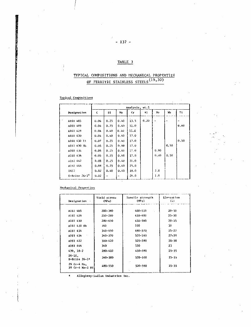
!
137
TABLE 3
TYPICAL COMPOSITIONS AND MECHANICAL PROPERTIES
OF FERRITIC STAINLESS STEELS (19,30)
Typical Compositions
Analysis, wt.Z
Designation C Si Mn Cr Al -- Nb Ti
AISI 405 0.06 0.25 0.40 13.5 0.20 - _ _
AISI 409 0.06 0.25 0.40 11.0 0.40
AISI 429 0.06 0.40 0.40 1'.0
AISI 430 0.06 0.40 0.40 17.0
AISI 430 Ti 0.07 0.25 0.40 17.0 0.50
AISI 430 Nb 0.05 0.25 0.40 17.0 0.50
AISI 434 0.05 0.25 0.40 ;'.0 0.90
AISI 436 0.05 0.25 0.40 17.0 0.80 0.50
AISI 442 0.08 0.25 0.40 21.0
AISI 446 0.08 0.25 0.40 25.0
18/2 0.02 0.40 0.40 18.0 2.0
E-Brite .26-1A 0.02 - - 26.0 j 1.0
Mlechanical Propert ies
Yield stress Tensile strcuigth ElongationDesignation (MiPa) (MPa) _ )
AISI 405 280 380 400-510 20-30
AISI 409 250-280 450-480 25-30
AISI 430 280-450 450-580 20-35
AISI 430 hb 340 550 30
AISI 434 340-450 490-570 25-27
AISI 436 340-370 520-560 27 30
AISI 422 310-420 520-580 20-30
AISI 446 340 550 23
439, 18-2 280-410 450-590 25-35
E-Brite 26-1* 340-380 520-550 25-35
29 Cr-4 ilv29 Cr-4 14-2 Ni 480-550 520-590 25-35
* Allegheny-Ludlum Industries Inc.
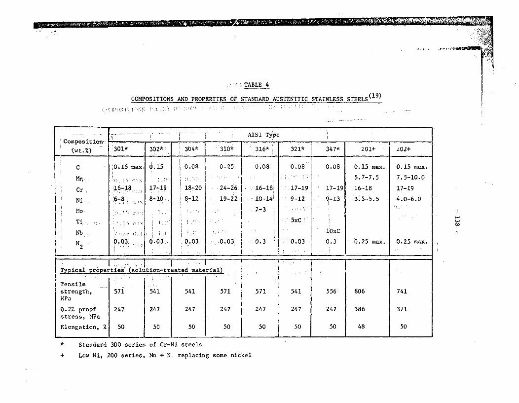
11 ,== Sig I I Ill -qI N
r o"
.j
I1 TABLE 4
COMPOSITIONS AND PROPERTIES OF STANDARD AUSTENITIC STAINLESS STEELS(19 )
s -- I | r AISI TypeComposition -_ , ;
.(wt.%) ' 301* 302-* 304* 310* 316* 321* 347* 201+ 102+
C i0.15 max. 0.15 0.08 0.25 0.08 0.08 0.08 0.15 max. 0.15 max.
Mn, ' >. ' 5.7-7.5 7.5-10.0
Cr 16-,18 17-19, 18-20 24-26 16-18 .17-19 17-19 16-18 17-19
Ni 6-8 8-10 8-12 19-22 10-14! 9-12 9-13 3.5-5.5 4.0-6.0
M MO. 2-3 1
* Ti. ,. . !' - .. ,, , .5xC
Nb i lOxC
N 0.03 ,0.03, 0.03 0.03 0.3 3 ' 0.03 0.3 0.25 max. 0.25 max.2
_ _ _ _ _ _ _ _ .- _ _ ._ _ . .3 ._ __._ _ ? . ..
I, -; K I T !I{.Typical properties (solution-treated material)
Tensilestrength, 571 541 541 571 571 541 556 806 741MPa
0.2% proof 247 247 247 247 247 247 247 386 371stress, MPa
Elongation, s SO 50 50 50 50 50 50 48 50
* Standard 300 series of Cr-Ni steels
+ Low Ni, 200 series, Mn + N. replacing some nickel
I
Loco
I

a
TABLE 5
IOFSOMI:TANDAR GKADI.S OT MARTSIlC S8)%) OF SOME STANDARD) GRADE.S OF MARTENSITIC STAINLESS STEIELCOMPOSITIONS (wt.
. Designationor Type' - Mn-- Si. P S Cr Ni Other
Number ; - ( C ! :; t(max) (max) (max) (max) Elements
403 o0.15 mag 1 i.00 o 0.50 0.040 0.030 11.50-13.00.
;410 0.15 'max 1.00 o 1.00 0.040 0.030 11.50-1Qi50
414 0.15 max 1.00 0.040 0.030 11.50-13.50 1.25-2.50
416 0.15 max -1.25 1.00 0.06 0.25 min .12.00-14.00 Mo: 0.60 max
416 Se_ 0.15 max :1.25 1.00 0.06 0.06 12.00-14.00 Se; 0.15 min
420 Over 0.15 1.00 1.00 0.040 0.030 12.00-14.00
431 0.20 ma, , 1.00 1.00 0.040 0.030 15.00-17.00 1.25-2.50
440 A 0.60-0.75 1. 00 1.00' 0.40 0.030 16.00-18.00 Mo: 0.75 max
440 B 0.75-0.951 1.00 1.00 0.040 0.030 16.00-18.00 Mo: 0.75 max
440 C 0.95-1.20 1.00 1.00 0.040 0.030 16.00-18.00 Mo: 0.75 max
w~cI
I. I 1 ") . ,I
I ; � )I I, .. r: ; . i ~
f j
a
f
I . !) . , � ,, I -f , ! ; , : . : . ;),-. ! ! : T ! ! 1 -_ I .....! , , ..I , ' : t

'! �,v�A�!
I
TABLE 6
COMPOSITION AND TYPICAL PROPERTIES OF PRECIPITATION-HARDENABLE STAINLESS STEELS( 9,46)
(C) (C) (C)Alloy , ,~ , Major Elements (wt.%)*' 0.2% Y.S. U.T.S. Elongation
R {;, , ,,(MPa) ('Pa) (%)
MARTENSITIC ALLOYS
C Cr Ni Mo Al Cu Ti
Ph 13-8 Mo 0.03t 12.75 8.2 2.2, 1.1 1470 1575 1217-4 PH 0.04 16 4'.3 3.3 1295 1400 1415-5 PH 0.04; 15' 4.6 , 3.3 1225 1330 14Custom 450 0.05' 15 ' 6 0.8 1285 1365 14Custom 455 11.75' 8.5, 2.25 1.2 1540 1610 12
SEMI AUSTENITIC ALLOYS
C Cr Ni _ Mo Al _
17-7 PH 0.07 17 7, 1.2 1330 lb35 915-7 a)"' '.0 15.1' 7.1I' 2.2 1.2 14 35 1505 7AM 350 0.1 16.5 "'4.25 2.7 f 1225 1442 13AM 355(a 0.13 15.5 -4.25 2.75 ; 1220 1470 14
AUSTENITIC ALLOYS
U C Cr Ni Mn Si P Cu Mo
17-10OPH 0.12 16.7 10.2j 0.75 0.5 0.28 610 950 25IiHN 0.3 18.5 9.5! 3.5 0.5 0.25 83.0 1120 1817-14 Cu Mo 0.12 i6 14 0.75 0.5 '3 '2.5 - - -A 286 (b) 0.5 26 15 1.2 700 1000 2521-4-9 0.4 21 4 9 650 1050 14
I
(a)(b)
(c)
balance iron0.1% N ..
2% Ti, 0.15% Al Y'-forming,,properties in fully-aged condition

. 1 ...... " I _. - 1 ,11 MM
TABLE 7
COMPOSITIONS (wt.%) OF SPECIAL STAINLESS STEELS AND NICKEL-BASE SUPERALLOYS()4 7 52
Alloy C Cr Ni Fe Mn A. Co Mo Nb + Ta.. .w .... I .-
Cu Ti w
Ni-base -, ' - '' _ - ' __'i '
Inconel 600 0.08 15.5 76 8 0.5 - - _ _ _ _
Inconel 601 0.05 23 60.5 14 0.5 1.35 _ _ _ ' - _
Inconel 625 0.05 21.5 61 2.5 0.25 0.2 _ 9 3.65 _ 0.2 _
Hastelloy C-276 0.021 15.5 Bal. 5.5 1+ - 2.5 i6 _ - 3.8
Hastelloy C-4 0.15 i16.3 Bal. 3+ - 0.2 2+ 15 , - 0.5 -+ i +
Hastelloy G 0.05 22.3 Bal. 19.8 1.5 - 2.5k 6.5 2 2 - 1
Monel;400 - 0.2 - 66.5 2.5' 2 _ _,0- , 31.5 _ _
Alloy C. Cr Ni Fe Mo Mn Cu Al Nb Ti
Fe-base'
Incoloy 800 0.05 21 32.5 Bal. _, 0.75 0.38 0.38, - 0.38
Incoloy 801** 0.05 20.5 32 Bal. _ 0.75 0.25 - _ 1.13
Incoloy 825 0.03 21.5 42 Bal. 3 0.5 2. .5 0.1 _ 0.9
AL 6X' 0.03 20 24 Bal. 6 1.5 _ _ -_
Sandvik 2RY65 0.02 19.5 25 Bal. 4.5 1.8 1.5 - j
Sandvik 2RE10 0.02 24.5 20 Bal. - 1.8 - _ _
Sandvik 2RE69* 0.02 2.5 22 Bal. 2.1 1.7 - ,
UHB 904L 0.02 1 20 25 Bal. 4.5 1.75 1.5 _ _
JS 700 0.03 21 25 Bal. 4.5 1.7 - - I 0.3 _
AISI 310 0.25 25 20 Bal. - 2+ - - -
Carpenter 20 Cb-3 0.06 20 34 Bal. 2.5 2 3.5 - ++ .
Uniloy-332 0.05+ 20.5 32.5 Bal. - 1 - _ _
I
*
maximum
contains 0.12Z N
++ Nb + Ta stabilized
** y'-strengthened! I
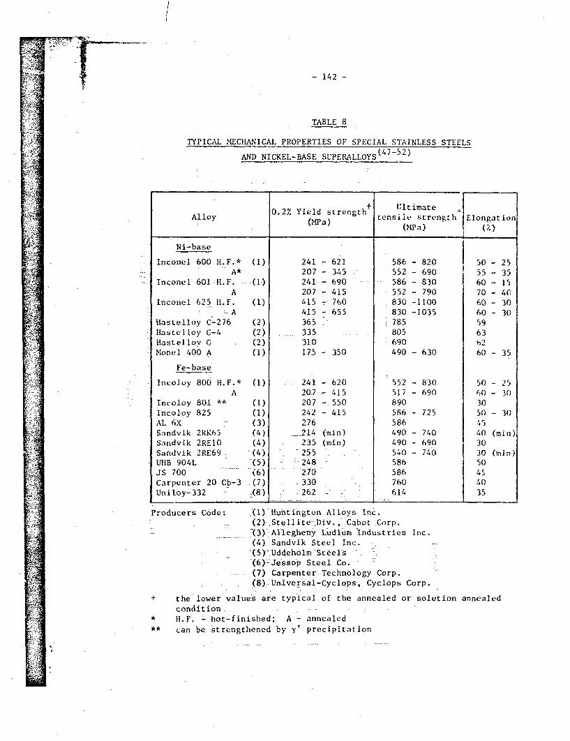
4i~lT
] l
11tt
A-
I.I,r
rTIS-"q I
- 142 -
TABLE 8
TYPICAL MECHANICAL PROPERTIES OF SPECIAL STAINLESS STEELS
AND NICKEL-BASE SUPERALLOYS( 7 - 2)
0.2% Yield strength Iultimate _Alloy 0M2a tensile strength Elongation
(mpa) (MPa) (%
Ni-base
Inconel 600 H.F.* (1) 241 - 621 586 - 820 I 50 - 25A* 207 - 345 552 - 690 55 - 35
Inconel 601:H.F. (1) 241 - 690 586 - 830 60 - 15A 207 - 415 552 - 790 70 - 40
Inconel 625 H.F. (1) l415 - 760 830 -1100 60 - 30-A 415 - 655 830 -1035 60 - 30
Hastelloy C-276 (2) 365 785 59Hastelloy C-4 (2) . 335 805 63Hastelloy G (2) 310 690 h2Monel 400 A (1) 175- 350 490 -630 60 - 35
Fe-base
Incoloy 800 H.F.* (1) 241 - 620 552 - 830 50 - 25A 20.7 - 415 517 - 690 60 - 30
Incoloy 801 ** (1) 207 - 550 890 30Incoloy 825 (1) 242 - 415 586 - 725 50 - 30AL 6X (3) 276 586 45Sandvik 2RK65 (4) 214 (min) 490 - 740 40 (min)Sandvik 2RE1O (4) . 235 (min) 490 - 690 30Sandvik 2RE69. -(4) - 255 540 - 740 30 (min)UHB 904L (5) 2:48 586 50JS 700 (6) 270 586 4'Carpenter 20 Cb-3 (7) - 330 760 40Uniloy-332 (8) ,-262 _ - 614 35
Producers Code: J(1)(2)(3)'(4)t5)'{6):-(7)(8)
Huntington Alloys Inc.Stellite Div.., Cabot Corp.'Al-legheny Ludlum Industries Inc.Sandvik Steel Inc.,Uddeholm7Steels.-.Jessop Steel Co.Carpenter Technology Corp.Universal-Cyclops, Cyclops Corp.
- the lower values are typical of the annealed or solution annealedcondition
* H.F. - hot-finished; A - annealed** can be strengthened by y' precipitation
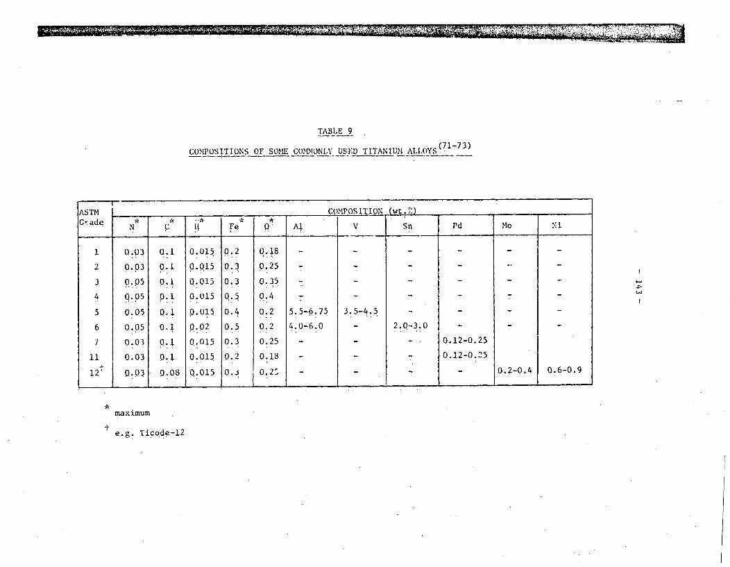
oil 111111 I -M , III I 11, , I
TABLE 9
COPIOSITIONS OF SOMECthOtNLY USED TITANIUM ALLOYS .?
ASTM _ COMPOSITION (wt.,')
G'~ade * * -N. : U F Al V Sn Pd Mo Ni
1 0.03 0.1 0.015 0.2 0.18 - _ _ _ _
2 0.03 0.1 Q.015 0.3 0.25 - _ _ _
3 0.05 0.1 Q.015 0.3 0.35 _ _ _ _ _
4 0 .05 0.1 0.015 0.5 0.4 _ _ _ _
5 0.05 Q.1 p.015 0.4 0.2 5.5-6.75 3.5-4.5 _ _ _ _
6 0.05 0.1 0.02 0.5 0.2 4.0-6.0 _ 2.0-3.0 _ _
7 0.03 0.1 0.015 0.3 0.25 - _ _ 0.12-0.25
11 0.03 0.1 0.015 0.2 0.18 - _ 0.12-0.25
12 0.03 P.08 0.015 0.i 0.2 -10.204 0.6-0.9
*maximum
e.g. Ticode-12t

, t1
1~
i ~ ~ ~ ~ ~ ~ ~ ~ ~ ~ ~ ~ ~~-- l 4 -
TA " LF I 0
iEfA4A7~~JTE OF S~OME~ COMON( Y US D~ T.I TAN I i'X ALLOY0 S (71- 731)
AS TM
(ra id t ;
()2 Y.S. (Mi'a) t.T .S. (0ai,)
ali L. ':Ix.X . . -Mill.
E I~n 'it jifl I ( :) i
Yi .
--3
.~I
1 Ž
1 70
275
i 80
830
795
'75
11o
345
'31 0
450
-5.5 1
6b55
450
31 ()
240
345
450
5(1
8' 5
83
3..5
2 ; (
483
-.,- 4
20
18
I 0
I 01 f)
2()
18
I
I
I

q II
- 145 -
TrABLE I I
STRENGTH AND) FbLACTIURE 1'ROPERT I S OF ., -TITAN I C AL.LOYS IN
THYE ~'ILL ANNEALED1 CONDITION'
Ti
Ti
(). 2' : Y j cl dl 1. 1 . l A .1K K~Al hIov'2. .*dS I: C I SCC(
(MPi. (OIPa) (MI'I rI )1) ( 1. :1)
-50A 293 - 54, 60.4 66.4
- . 5 '2 705 1 2660
i- 5A I - ' . 9ST1 89 2 9 54 S( .'9
* Takell as the v'aitle of appl iedtest in;g.
st ross i ntens ityv at 36(0 minutas ot

TABI.E 12
NOMINAL COMPOSITIONS OF SOME COMMONLY USED) WROl'(:IIT COPPERS AND COPPER ALLOYS( 10)
C.D.A.# Name Numi aa 1 Cmpno itin
.(u O P Be Zn Sn Si____. _ _ ___ .l___ _ ._ _ _ _ _ _ _--- -- - - - - -. ... ............ ___ _
102 Oxygen-free copper 99.95
110 Electrolytic tough-pitch copper 99.90 0.04
122 Phosphorus deoxidised copper 99.40 0.02
170 Beryllium copper 99.5 1.7
220 Commercial bronze 90.0 10.0
260 Cartridge brass 70.0 30.0
280 Muntz metal 60.0 40.0
505 Phosphor bronze 93.75i 1.2;524 Phosphor bronze 90.0 10.0
651 Low-silicon bronze 98.5 l.
655 High-silicon bronze 97.()
706 Copper-nickel 10% 88.7
715 Copper-nickel 30% 70.0 I
614 Aluminum bronze, D 91.0
632 Aluminum bronze "2.0 I
674 Manganese brass 53.5 36.5 1.0675 lManganese bronze, A 58.5 39.0 1.0
675~~~~~~~ . _ _ _ _ _ _. _,i _ _ ._ _ ._ _. _ _-
(Wt .%)
Ni Fe A1 Mn
5
10.0 1.3jM0.0,
2 2.05.0 14.0
-.1 I- _
7.09.0
1.2 2. 30.1

- 14 -
TABLE 13
RANGE OF MECHANICAL PROPERTIES IN THE ANNEALED CONDITION
F OR COM('MNL.Y IS}:D WROUGHT COPP ERS AN!', COPPER ALLOYS )
C.D.A. Name 0.5,, Y.S. UI.T.S. Elongation
Series (MPa) (0D'a) (%)
100 Coppers 70 220 45-55
100 High copper 70-!20 03-490 32-55alloys
2UO Brasses 70-147 240-380 45-66
300 Leaded brasses o4-140 260-370 45-65
400 Tin brasses 70-175 270-390 40-65
500 Phosphor 9;;-196 2S0-460 4S-70bronzes
600 Aluminu.- 210-378 525-640 18-45
bronzec
600 Silicon 105-147 280-392 55-60bronzes
/00 Copper-nickel 90-210 300-490 35-45
700 Copper-nickel 126-189 340-420 40-50zinc
Manganese brass 84-240 320--490 28-60
Manganese bronze 210 b55 33
Aluminum brass 190 420 55

II
TABLE 14
COMP.ARATIVE CREEP RATES OF PURE COPPERS AT 15()C ( 1i)
Stress to produce a creep rate of
0.0001% per houlr
I.I
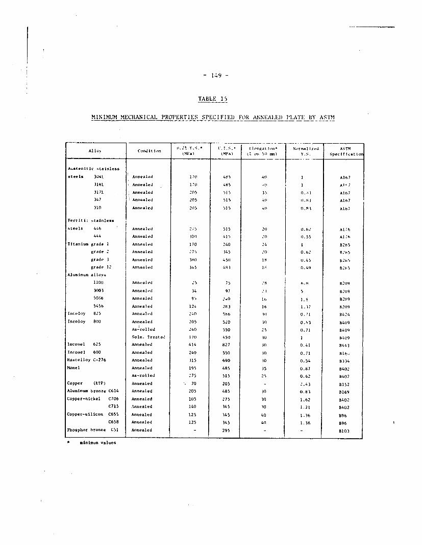
- 149 -
TABLE 15
Mfl INUM M MECHAICAL PROPERTIES SPECIFIE) FOR ANNEAI LED ILATEl BY ASTM
Alloy ConditIon EI.gt Y.S.i JT... 1 nt .on t N rmall- Ie..d A.STM
(IN'a) IMPA) kZ on 50 mm) Y.S. 8pecltlcaEion
Austenitic stainless
steels 3041. Annealed 170 485 40 1 Al177
316L Annealed 1I'0 485 I A1 1l
3171. Annealed 205 515 35 0. A I A167
347 Annealed d205 515 4I o .s 3 A167
310 Annealed 205 5S 5 41) 0 .8I Alt7
Ferriti: stainless
steels 446 Annealed i 515 20 0.62 AAl; 6
444 Annealed 31 415 2n 0 0.55 Al 6
Titanium grade I Annealed 170 240 24 1 8265
grade 2 Annealed : 75 345 :()0.62 OBts
grade 3 Annealed 38( 450 18 0.45 b265
grade 12 Annealed 345 4SS l 0.49 2t 5
Aluminum alloys
1100 Annealed 25 75 8 1.8 H 209
3003 Annealed 34 97 1 5 B20(9
50 6 Annealed 95 2.4 It, 1.8 B209
5456 Annealed 124 283 16 1.37 B209
Incoloy 825 AnneA],ld 240 586 3n 0.1 B424
Incoloy 800 Annealed 205 5.0 10 0.'3 8409
As-rolled :40 550 2 5 0.71 8409
Soln. Treated 170 450 30 1 B409
Inconel 625 Annealed 414 827 10 0.41 8443
Inconel 600 Annealed 240 550 30 0.71 B1l6.
Hastelloy C-276 Annealed 315 690 30 0.54 B334
Monel Annealed 195 485 35 0.87 B402
As-rolled 2175 515 25 0.62 B402
Copper (ETP) Annealed . 70 205 - 2.43 B152
Aluminum bronze C614 Annealed 205 485 30 0.83 B169
Copper-nickel C706 Annealed 105 275 30 1.62 B402
C715 Annealed 140 345 10 1.21 8402
Copper-silicon C655 Annealed 125 345 40 1.36 B96
C658 Annealed 125 345 40 1.36 B96
Phosphor bronze CSI Annealed - 295 - - B103
.1 _ _ _ _ _ _ _ _ . _ _ _ _ _ _ ._ _ _ _ __I
* minimum values

I,~~~~~~~~~~~~ IS - 10
TABLE 16
VARIOUS COST CO(PARISONS FOR ENCINtERING ALLOYS
Cost Lost of fabricated Cost ratio onAlloy (S/kg) pipe (S/kg) the basis of Y.S.
I I~~~~~~~~~~~~~~~~~~~~~~~~~~~~~~~~~~~~~~
A36 mild sreel 0.75 I' 1.17 | 0.13
Copper 3.81 B 5.57** 2.53Copper-10; nickel 4.75 B 7.10** !.1Aluminum bronze 4.40 B 6.60** 1.0
3041. stainless steel 2.29 - 5.'8 0.883161. stainless steel 3.61 P 6.01 1.00310 stainless steel - 9.hO 1.32321 stainless steel 5.Ob P) 5.52 0.76347 stainless stee l 5.19 P 5.79 0 S0
26 Cr-1 Mo ferritic 5.57 _stainless steel
20 Cb 3 stainless steel 8.18 _Incoloy 825 7.96 13.1* 1.55Incoloy 800 5.35 P 10.5 1.43
Inconel 600 9.04 13.20 1.65Inconel 625 11.88 P 19.23 1.33Hastelloy C-276 17.16 23.43 2.22Monel 400 3.18 12.76 2.04
Grade 2 titanium 11.88 P 27.2 1.58Ticode-12 15.40 P 30.7* 1.41
Aluminum alloy 1100 5.17 P 7.87** 3.14Aluminum alloy 5036 4.77 P 7.12** 0.73Lead 0.77 _
based on quotations for pipe 91.4 cm O.D. x 2.54 cm w.t.
B based on quotations for billets
P based on quotations for plate
* assumes same fabrication costs as for similar alloys
** assumes fabrication cost is 50% of base metal price
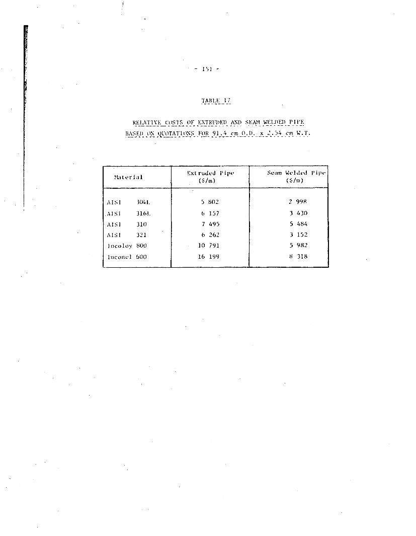
l
I
IIz- 151 -
I
'IAllLE -1-7
REi.AvriVE ;os~rs OF E.XTRUIj)FD ANI) SEANM WEI.DEfl 1P1 FE
BASED) ON jTAIS FOR 91.4 cm 0.!1). x 2. 54cmWT
xU ter!l aIExtruded P'ipe Seam Weldeed I'ipe
AISI 3)41. 5 802 2 998
AISI 3161. 6 157 3 4330
AISI 310 7 495 5 484
AISI 321 6 262 3 152
In)colov 800 10 791 5 982
Inconel 600 16 199 8 318

Z
- 152 -
TABLE 18
PROBABLE GROUNDWATER COMPOSITIONS OF CRYSTALLINE ROCKS
OF THE CANADIAN SHIELD(141)
Analysis Units Probable Range Maximum*1~~~I
Conductivity
KMnO consum.
COD
Ca2V
Mg2+
Na
Fe-total
Fe 2 +
Mn 2+
HCO 3
CO2
C1
S02-S4
N0-3
p03 -1 4F
sio2
HS
NH +4NO
°20d1p
02
pH
iS/cCm
mg/L
02 mg/
mg/L
mgIL
mg/L
mg/L
mg/L
mg/L
mg/L
mg/L
mg/L
mg/L
mg/L
mg/L
mg|L
mglL
mg/L
mg/L
mg/L
OLdHmgJL
n. 8
400O-41C
5-35
1.2-9
20-60
15-30
(% 20-40)
1-20
0.5-15
0.1-0.5
150-400
0-25
20-100
20-40
0.1-2
0.1-0.6
0.5-3
15-40
< 0.2-5
0.1-0.4
0.01-0.1
6-15
<0.01
tunnel water)
1 100
50
12.5
100
150
200
30
30
3
500
50
400
100
10
1
8
60
10
5
0.5
50
1
(Swedish
.I -4
* 95% Estimated probability that the maximum will not beexceeded.

I- 153 -
TABLE 19
SOIL RESISTIVITY CLASSIFICATIONS*(1 43)
Resisclvity Range Corrosivity(Q-cm)
0 - 1 000 Very severe
1 001 - 2 000 Severe
2 001 - 5 000 Moderate
5 001 - 10 000 Mild
10 001 + Very mild
* refers to steel pipe.

-- T--
- 154 -
TABLE 20
SOIL. ACIDITY CLASSIFICATIONS(17 )
Classification pH
Extremely acid < 4.5
Very strongly acid 4.5 - 5.0
Strongly acid 5.1 - 5.5
Medium acid 5.6 - 6.0
Slightly acid 6.1 - 6.5
Neutral 6.6 - 7.3
Mildly alkaline 7.4 - 7.8
Moderately alkaline 7.9 - 8.4
Strongly alkaline 8.5 - 9.0
Very strongly alkaline > 9.0

- 155 -
TABLE 21
EFF'ECT OF TEMPERATURE AND CHLORIDE (CON(CENIRATION
ON MILD STEEL CORROSl(oN 'M
7 NaCl temperature
I V (IC)_ _ . .. _ I _ _ _ _ _ ,
Corrosion Rate(ruSm/.? ,
0
0.002
0.05
3.5
20
75
20
75
20
75
20
0. 5 3
0.91
0.66
1.70
0. 79
2.16
0.61

TABLE 22
PITT ING POTENTIALS OF VARIOUS ALLOYS IN A 1000 m
CHLORIDE SOLUTlIO(N AT AMBBIENT TEMPERATURE -)
A Xlloy i Minimum Breakthrough Potential* Aloy ' Y(Volts vs. SCE)
A - - I- __ _r ntVnj ~~~~~~~AL.-6X 1.0+ (beyond range tested)
29Cr-4Mo 1.0+ (beyond range tested)
Hastelloy C 1.0+ (he':ond range tested)
26-1S I 0.98
216 C.95
20Cb3 0.55
- - 18-2 0.40
316 0.33
4 39 0.30
304 0 0.22
430 I 0.05
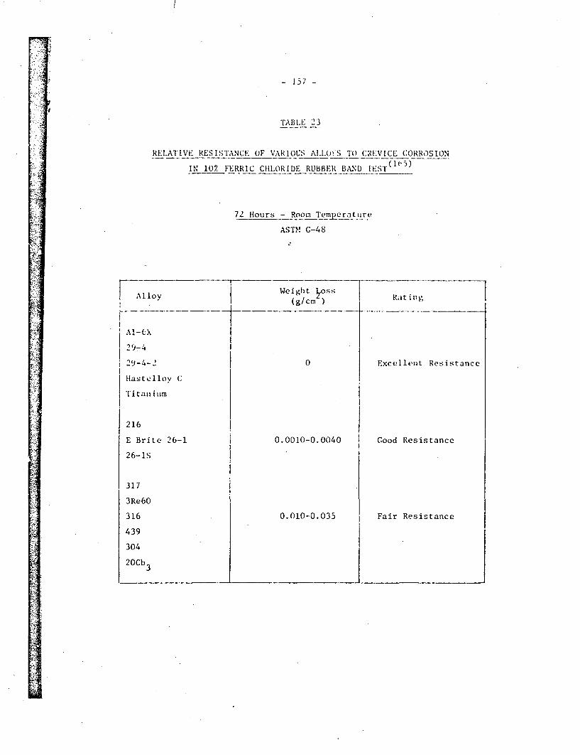
-157 -
TABLE 2`3
RELATIVE RESISTANCE OF VAR1OUS Al.1OW'S To CREVICE CORROSION
IN 10% FERRIC CHLORIDE RUBBER BAND TEST( )
72' flours - Room Temyc rat u re
ASTM G-48
-< Alloy Weight boss Rdting
2'9-4- 2 0 Excellent Resi.
,astellov C
T i tai tim
216 I
E Brite 26-1 0.0010-0.0040 Good ResistancE
26-is
317
3Re60
316 0.010-0.035 Fair ResistancE
439
304
20Cb3
.

EST ELIMM-77-7% � �%27A I
1ABLE. 24
I:YC 1 :-IOLYBD E NUMl Co~NC I: Ni KAI 14 I~N THE: 0IDIP;..
24- It I- Cow.-tant A~p I ikd "ot vot iii . '.V:
k- LA I p Iwo I o all-' tt ~~~~~~I I3'tIlk. A I. I ~ ~Ink, S(j t ai Is Stvc-l AI Iy o - Al lov { No. I A lO','
+ 80¾)
+ 7001 O.-
+ 5ub 4
+ 401)- 4)4
+ 200.
+ I00* '
* loc<31ized corrosive attack
o No attack.
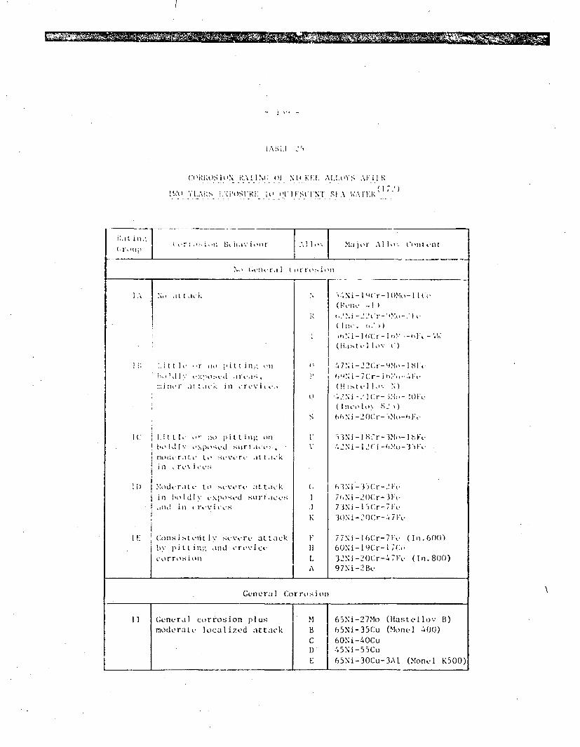
I
I =2_2�
Ct Ii~iaL)S tILN iV%!I NC oF N I K'!l AI.lUYS At'i lI-
1~~ i~lzS Mi isuizi~~~ B' fl I IKS(!:N[ SL.\ w~~~~n~lz
r:,t II.-
( rugI.( r : i *n Bchiiv iour I .,I IO . I Ma ) or Al II,1: C~i'ii ntf
.1o (li-Ilt-ral I I 11' 1,0�, i � 1:1
I kkdI
I::Ainor a! t ir in ,rrcv it
II)
I.ilt t I ' I: :o p i tt i II,' ollI, ,o I dlv pc> -po .vd s u ir i ict , 7.,
moci, r ai ,. to I cv crc at tac,-kI n rr vvlrC !;
:~dur~i v tt I 'I'%, rt, Lt~takki n h it IdI v txpo stvd su r 1Kurt-~;
a n di i n r1 r I i uC s
COnIS i "-,t Ol L I stvvrv at tackbY pitt im, and crL.WiCk
corrosion
S
I.1
K
FH1I-
u-.N i -I lo(r- I(o-. I I
~ N i -2 2 C - C h - I S
!4 7 i -21 r- 3No- I S-Vth N i- 7C.( i -h - FL-
6 N i I ( r - 2 F1 O
7 n i- I II% r- 7.'O 0N i -2 0 Cr--~ 7 Pc) %:
773Ni -1 8 -r-7No- (In. 00)6O2N i- 129Cri- ( C1 L
737 N i - I Cr -- 7 Ft (I n. 8 00)
97Ni-2Bu
General Corrosion
II General corrosion plus N 65Ni-27Mo (Hastetlov B)
moderate localized attlack B 65Ni-35(:u (Monel 4(0)
C 6ONi-4OCu1) 45Ni-55Cu1- 65Ni-30Cu-3Al (Montl K500)
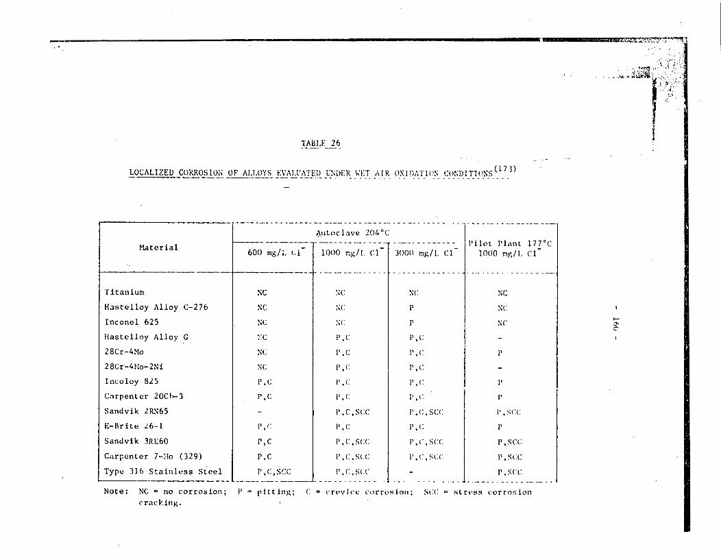
il
4AI~~~~I
TABLE 26
LOCALIZED CORROSION OF ALLOYS EVALUATEI) UNI)ER WET AIR OXID!)ATION CoNI)!DTIONNS(13)
Material6C
__ +
Titanium
11astelloy Alloy C-276
Inconel 625
Hastelloy Alloy G
28Cr-4Mo
28Cr-4Mo-2Ni
Incoloy 825
Carpenter 2OCf -3
Sandvik 2RN65
E-Brite 26-1
Sandvik 3RE60
Carpenter 7-'Mo (329)
Type 316 Stainless Steel
Autoc lave 204 c
)O mg/;. L 1000 mg/l. CI 30(
NC NC
NC NC
NC NC
':C P,'c
N(: ~~~~I', (
NC 1;
PN ciC
_ I' .C, Scc
1. 'C P' C
1', C 1), (:, S(:(
P.c P C( S( .
P,(c,Scc P.C C5S((
1) mg/l. ClPilot Plant 177°C
1000 mg/I. CI
NC
P
P1 C.
P1 C
i', C
1. C. .CC
i',(
P',(:
1', ( ; S(:
P', C, S(.C(
NC
NC
NC 3'~
P
1', S(C(:
P, c
P. SC(:
Note: NC = no corrosion; P = pitting; C = crevi(e corrosion; SCC = stress corrosioncracking.

TABIK1_1: 2_7
RESISTANCE OF VARIOUS (RtI)ES OF HAS'EI'LOY-(:'I'O I'iR(RANUL.AR, CRI'VI(:I AN) STRESS CORROSiON'SON )
rvu Ie it re's.
lot e re rn.vol.er rr. fIn In I orris luonAl I oeel i-i ti-I q ,.i . .ii t r rI r: R1 r., ( .I
R.r . 9. li j311 .(1 ( 1 S Mg -
__ _ ~~~~~~~~d. A.. I. I
I A 1.1
- Ii {, ,1 (' i)
Al loy ( s . (. (. I *;.t 1 Ae I .-I l.. 1. 1 h1iN Ne nI 1 .11 ; 1 . 1'. 1 1 Ii Ye' Sl ee-
1 .e I.l r I .; 4 r, YesI t 1i 1i . . ;. i, Ye-s Yea
t-Irl .i" 1 .d .I. Y,-' YenAggi,,mecr..et 1V '. ;Y.. Ye'
Al loy t-.ib i (06 (h.01 .1)(1 Silt toi A. eleal-i I (1 ; ! Neene ' leI At (iI h 5 1. I NSot None
. .e W 1 It 1.1 iNn- YesI I at 10 I,;( I, S No.- None
Alloy (.-2/b 31t1 (1.00. 9) 101)4 Solut ton An:-.aii-d 1.') 1 f, N.-ne NoneI it At 1( .l I () 1.1 Nilne Yes
I h At 7l'C 11.4 1 .9 None YesI Ii at lO t' I.( l e, .I None Ye'
Alloy (:-2;6 31 (( 1.1)(04 (I,01 eloit Ion Ansen l.d I .0 I. None None
Ii AIt 711,;' 1 I' None NoneI h at r8;1l 1.2 1.9 None NoneI Ai dt I 1 '( 1. 5 1 .2 N,,ne NoneF(rtieri Cioled .i. 4 I (I No ne None
Aggl-rit.r. t: c|:. I Nrne None
Alloy C-4 71)1 0OObh 1).104 Soliit fIon Anriiealvd .1. Il. Yes NoneI 11 .1t Ui7<of 1 4- 7. 4 1.1 Yen None
_ . . . i.. ..r. .ii.e, I F, . led 1. . . .0 Y". None
(1) Heat Treatments: Furnace c... I-d trim 1200 or 1 22.1 to 54')° in 1.5 h.Agglomerating: Heat In 4 h to l170-C. hold I h. co.l tii 112WC and hold I h, then cool to belerv 565C In ' 0.5 h.
(2) Ratio of rate ot given spe'clen dfvide by r.te o/f olitfon ain.iled'. .ee tnen tin boiling 50% H So.. with and withoutferric sultate.
(3) Specimen vith six crevftce.
(4) U-beted specrimenee.
(5) Alloy contains 0.43' If to stabilize' carbon.

I
,. '
11- - 162-
TABLE 28
SUKMARY OF OXIDATION DATA FOR UNALLOYED TITANIUM (_1)
Ti- Referunce NcTemp. °C Environment Consumption in ref. (81)
6U 3.5% NaCl+96.5,I H-^, 0.24 29air-saturated solution
3.5, Na(:1+96.5% H 0, 0.24Ar-saturated,Exposure time 146 d
120 Steam, 120°C, pll 7, 0.0025 '0Exposure time 2 a
130 3.5 NaC1+96.5' H-0, 1.6 29air-saturated solution
3.5': NaC1+96.5,; It 0. 5.6*Ar-saturated,Exposure time 146 d
200 3.5, NaCl+96.5. tWOV, 3.2 29air-saturated
3.5' NaCI+96.5'' It-o,
Ar-saturated,Exposure time 146 d
252 Boiler water, pH 10-11, 0.007 10Exposure time 234 d
315 Simulated PWR-water, pHi 10 0.2 - 1.6 10*;-Exposure time 80 d
360 Degasified L -O, pH 9.5 0.16 10Exposure time 107 d
400 Steam 400°C, 10 MPa 0.35 45Exposure time 417 d
* Based on weight loss. All otherthe basis of a weight gain.
values were re-calculated on
** No hydrogen absorption or effect on mechanical characteristics.
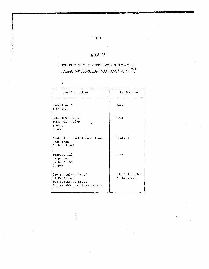
- I #b3 -
TABL.E _29
RELATIVE CREVICE CORROSION RE1SIS'TANCE OF
METALS AMI) ALLOYS IN QUIET SEA WATER ( HI)
Metal or Alloy Resistance
Liastellov C InertTitanium
90(:u-lONi-l.5Fe Best7oCu-30Ni-O.5FeBronzeBrass
Austenitic Nickel Cast Iron Neut ra ICast IronCarbon Steel
Incoloy 825 LessCarpenter 20Ni-Cu AlloyCopper
316 Stainless Steel IPit InlitiationNi-Cr Allovs At Creviccs304 Stainless SteelSeries 400 Stainless Steels

- 164 -
TABLE 30
DEPTH OF ATTACK AND CORROSION RATES OF COPPER AND COPPER ALLOYS AFTER 735 DAYS
IN QUIESCENT SEA WATER WITHOUT CATHODIC PROTECTION(201 )
Alloy Name
ICDA No.
Depth of Attack (mils)
Cre~vice(2) Surf_ _ .
Deepest Average Deepest Average
4 3 I,
9 6 1 1
Avvrage
uorros wn z '-
Raste (-.l-y)0
Copper
Copper-Beryllium
Copper-Cobalt-Beryllium
Commercial Bronze, 90%
Red Brass, 85%
Cartridge Brass, 70%
Yellow Brass, 66|
Muntz Metal, 60%
Admirality, Arsenical
Naval Brass, Uninhibited (Grade A)
Phosphor Bronze, 10% D|
Aluminum Bronze, 5% Al
Aluminum Brcnze, 9% Al
Aluminum Bronze, D, 7/ Al, 2Z Fe
High Silicon Bronze A
Copper-Nickel, 10Z
Copper-%ickel, 30%
Copper-%ickel. 30% Ni, 5% Fe
172
175
220
230
260
26i.
280
4 43
464
5!24
606
!612614
65Si
706
71i
716
3
61
12 (6)
(6)
- (6)i
0
12
1_
0
4 3
2
_(6)
(6)
(h)
,(b)
.3
'1
6
(l
0
26(
-4
0
1 3
1 5
6
0
I0
C)
)(5) .
(6)
(6)
(h) !i.
( 6
0( 6)
-(h)
0.37
0.46 kd)
(1. 1 ) (.: )
11.08 td;
,.0n (7)
(. 31 ad)
.31 (d)
0. ot, J(
O. ;.. (o2
tO. (2I)
to.:_ (K.
1.I I m(2
r(*o' ( '
0). ?. (21)
(3 .(it,
.1). )..:
(I
(I
(1) There were no measurable pits and no detectable weight
cathodically protected with zir.c anodes.
loss on specimens which wer.
(2) The deepest and average of the ten deepest points of attack .issociated with a crevicv.
(3) The deepest and average of the ten deepest points of attack on the surface not associated
wiLh any known crevice.
(4) The average corrosion rate is given for comparison only. Since uniform attatk is assured
in its calculation, the average corrosion rate is applicable only to those alloys which
did not experience localized attack or de-allovi.ag. (d) - de-alloved.
(5) Alloy pitted on surfaces, but pits were too narrow for accurate measurement of depth of
attack.
(6) Copper deposits from de-alloying made accurate measurement of depth attack impractical.
* 1 mil - 0.001 in = 0.025 mm
spy - mils per year.
I'

--- I M I am ;Iowa
TABLE 31
RVCE(;ORROSION TEMPLRATURES (0 C) OF VARIOUS AL[LOYS IN 10% FcCl 3*61120 SOLUTION
29Cr-4Mo Has telloyC-276
Streicher (163)
Steigerwald (166)
Garner (204)
Brigham (130)
La Que (205)
Kovach et al. (155)
Coulter et al. (167)
Timet (72)
Tapping (206)
Lowest Reporte~d
304S. S.
,RI
-2. 5
-2. 5
0
-2.,5
316
-RI
- 2. 5
26Cr- IMo Al -6X Inconel625
C.P. TiT-O2PGrade 2Grd7
<RT
<SO
20-22. 5
50
RI-SO >,50
30/ 35**
28- 30
17. 5-20
23 50
>SO
>48
1 7.5 .'50
Ti-O. 2PdGrade 7
RIT-50*
RT-50*
45
4 5
65-75*
>50
65
65-75*
>50
< 100
>48
65
RI 0ON
>100
I
>100- 2. 5 .RI'
* (T1-T2) 3 resistant at T~ but not at T12
** Welded/not welded
RTI room temperature

::.,-4 T- 166 -
1600
0
w
wa-LiH
600LFe 10 20 30
WEIGHT PERCENT CHROMIUM
i 1 j'j i' ;ins Diagram Showing ,-r ooep in F.-Cr Al loys ContcainingLess Thmi 0. 01, Carbon or Nit rogen (So lid liinks) andAl los Containing 0. 1 to 0. 2: Carbon or N it rogun (Dot ttd!Ants)(18)

- 167 -
air cooled(HAZ) as-weld
-50_ (HAZ)
V / If / type 43XU
0-40 0 40
TEMPERATURE 0C
FIGURE 2: Effect of Post-WVvld Annealing on thi Imp;c(tPropert ies of 17/ chromium Stel (25)
10
8
w
z
rr4
202
4)
rl
v-_ _- , _ L .
-40 0CHARPY IMPACT
40 80 120IR/ 'SITION TEMPERATURE,'C
FIGURE 3: Effect of Ferritic Grain Size on the Impact TransitionTemperature of Commercial 17% Chromium SteeLs(25)

- 168 -
I
II1,i)o
I
1400
800
70C
60C
Ua)
00)D-EC)
f- 5 0 0
Proposed bfWil~iorns
1300
a/ I~ 'c
I ~~~I
'III I
2
U-
1100 C)
C,iOO
900
800
/.m
I ~~~~a + a'II I
0 .I 2 3 4 5 6 7 8 9
Atomic Fraction of Cr
FIGURE 4: Lower Temperature Portion of the Fe-Cr PhaseDiagram(18)
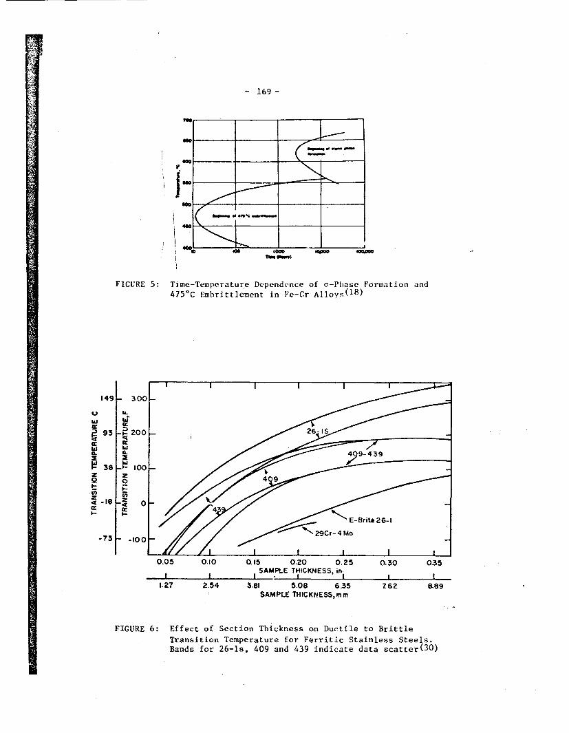
- 169 -
iI~me .,-
O* 0IC --
40 -__ --- mu leow
nhm 1M
FIGURE 5: Time-Temperature Dependence of a-Phase Formation and
475°C Embrittlement in Fe-Cr Alloys(18)
149
U
w
i 93
Qft
In
4 -18a:
- 300
Ba:.w'
-I.- 200x
wwa
-'*- 100
20
-Z 0
I.-
-73F -tool
0.05 0.10 0.15 0.20 0.25 0.30 0.35SAMPLE THICKNESS, in-I I I
1.27 2.54 3.81 5.08 635SAMPLE THICKNESS,mm
Z62 8.89
FIGURE 6: Effect of Section Thickness on Ductile to Brittle
Transition Temperature for Ferritic Stainless Steels.Bands for 26-ls, 409 and 439 indicate data scatter(30)

.- IR
,
V.,VA71
I
F77777K -J- 170 -
tL.
w
I
LUWw0
0
w
4-
I--
LU0
zLJ
Cl)LUJLUJ
0
LU)
LUJ
a-
I I I I50 60 70 80 90 100PER CENT (WT)
FIGURE 7: Phase Diagra for Fe-Cr Showing the Effect of8% NickelMT
.'.

~~~~~~~~~~~~~~~~~~~~~~~~ 7X 1200 12Cr-15Mo-2N l 171
140 12Cr-1l5Mo-2Ni120-
-- 1OO 12r-1. MOU6 80
0~~adnn (45 - -3V~9
., C1
~ :0r12Cr-1-5Mo-2Ni-0-3V CJ/
20 0-2
0 100 200 300 400 500 600 700 800TEMPER INOG TEMPERATURE ,0C
FIGURE 8: Effect of Tempering on Impact Resistance Showing aMinimum in the Temperature Range of Maximum SecondaryHardening (450 -5500C(
19 )

- 1 72 -
Chromium
Type 4'Type 410
f ,.,. *v fo 80 Nickel
FIGURE 9: The Fe-Cr-Ni Pihase Diagram, Isothermal Section
at 4000CC]8)

I
iIMONMEMM wb��
- 173 -
80
5001-
IN AREA
A604001-
0.
Cn,
9300I-'
200
100
ELONGAT ION
aC
40
20YIELD STRENGTH
I A l I I
'0 100 200 300Temperature, 0C
400 500
FIGURE 10: Effects of Temperature on Strength and DuctilitT8 ofMill-annealed Unalloyed Titanium (ASTM Grade 3)

I
----- .�
-1I I
II-
.; .
S.
- 174 -
6 I I I
700
0)C
4.'
4.'
CD
4.'0)E4)0,Cu
600
500
a
U
* NITROGEN
* O'-. YGEN
A CARBON
TENSILE STRENGTH
3000 A
1%
_ _ _ _ BEND DUCTILITY
\ "'A0% % =
1~ -' ==_ A -- - _ _
(D
EL
20 CDM
CDOa'
.o
o ae
200 o-
t lI%#%P-0 0.2 0.4 0.6 0.8
Interstitial content, wt %FIGURE 11: Effects of Carbon, Oxygen and Nitrogen on the Base-metal
Tensile 0jength and Bend Ductility of Arc Welds in UnalloyedTitanium .
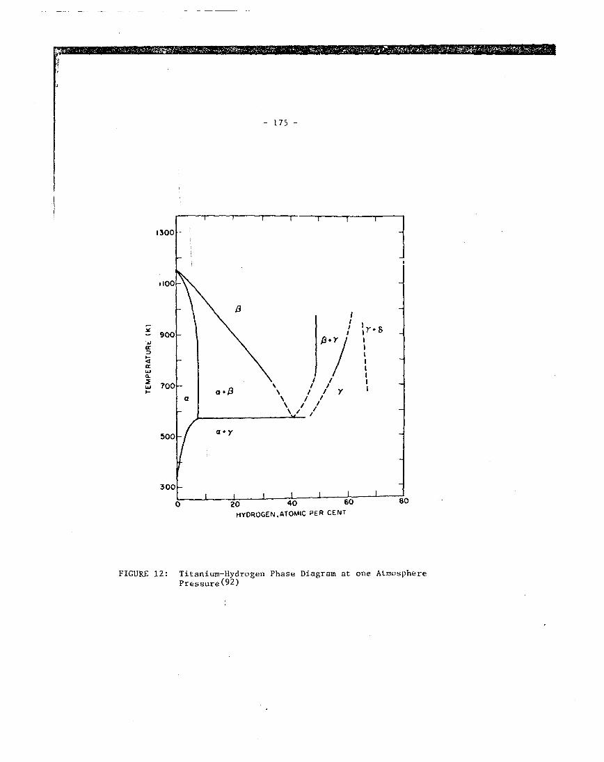
I 11 P 1 11121x� � �10-1:13
- 175 -
'AJ
I-.4
wr
a
0 20 40 60 80
HYDROGEN.ATOMIC PER CENT
FIGURE 12: Titanium-Hydrogen Phase Diagram at one AtmospherePressure(92)
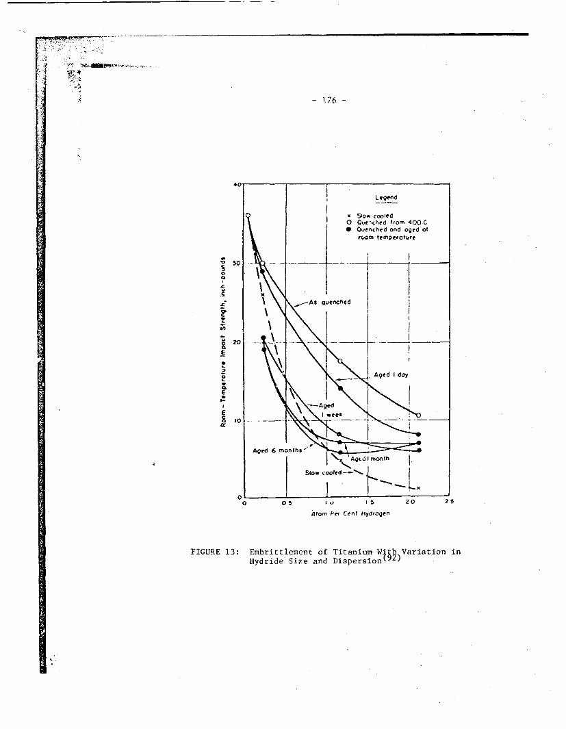
rppmv, . Tf?7 , , . ; Iw- - I , .
; 1 7
::. 1, .
I-,!
1�41 ;q�iI f2- --l. t
I - 1.76 -
101s
0
E
EI-Z
4tom Per Cent Hydrogen
FIGURE 13: Embrittlement of Titanium W'th Variation inHydride Size and Dispersion t2)
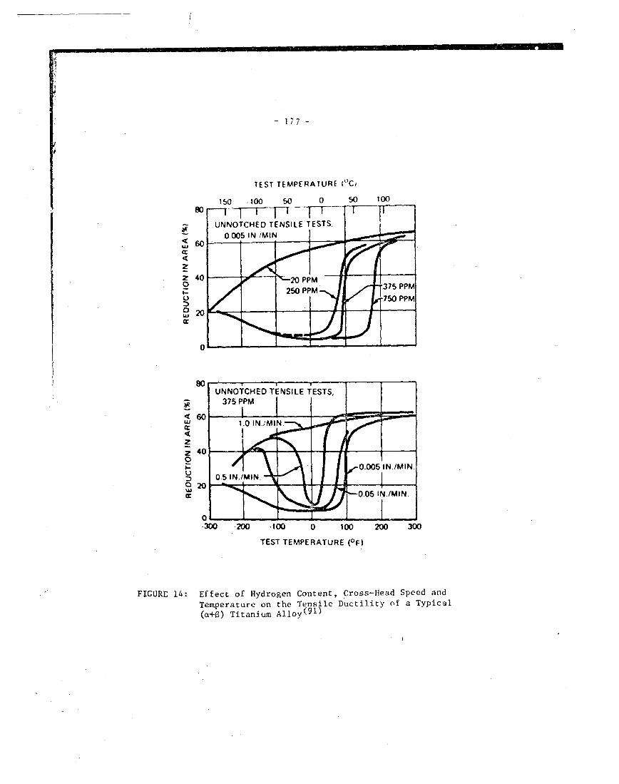
~~-
- I 1 7 -
TEST TEMPERATURE ("Ci
;w
2LU
zz2LU
cc
300 200 .100 0 100 200 300
TEST TEMPERATURE (OF)
FIGURE 14: Effect of Hydrogen Content, Cross-Head Speed andTemperature on the Tensile Ductility of a Typical(a+6) Titanium Alloy(91)

- 178 -
40%
300 I , orwXt~ I bus
M
0)h..
U) 200i. I 1 '1 1 O 1 #"I gI-llov 825
Ti code - 12
3 1 6 1. SS
1001A A AuminuAm & \ Titanium Gr.2
- - AlI tm intim 54 S4
* Copper
A
----... Aluminumr 3003
l
0 t00 200 300
Temperature, OC
FIGURE 15: Yield Stress-Temperature Data for Various Alloys Takenfrom the A.S.M.E. Pressure Vessel Code. All data aretaken from Section VIII, Division 2, with the exceptionof Inconel 625 which is taken from Section III. Thecurve for TiCode-12, which is not a code material,assumes the same temperature dependence as Titanium

� I � - I. 1. -. mm ;L4Z=a'Z��771j'040.i
desira'ble shift
undesirable shift
ER = rest potentialEP -. passivation potential
EA - activation potentialE Qtt - pitting potential
E triins - transpassive potential
C
C / \' pitting- /
active passive
'mr
ER EP EA EP, Etrans
potential, E -
Figure 16: Schematic Illustration of Anodic Current Density VersusElectrode Potential Curve for Stainless Steels
z
ive

-gm
- 180 -
FIGURE 17: Potential-PH Equilibrium Diagramat 25OC(12 7)
for the System Iron-Water,
A:'
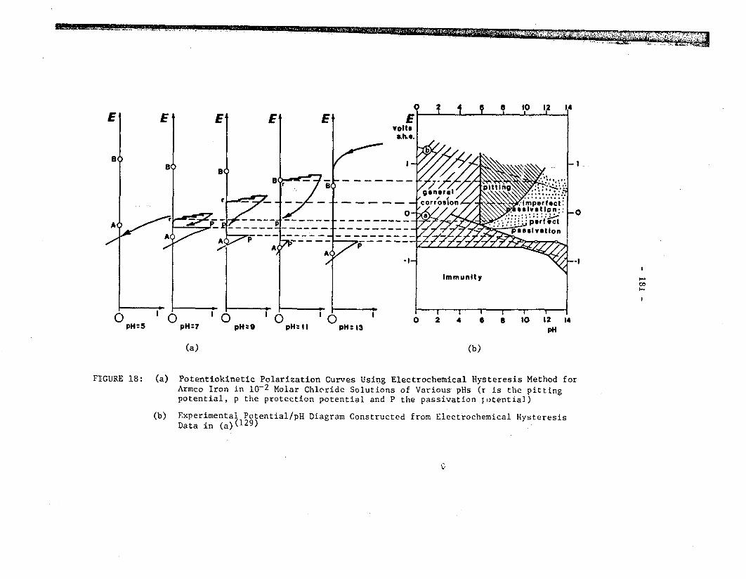
WE-.. . ¶, I I f am. r1f I ..- 'I I~ I '-
I
I-
I-
pH
(a) (b)
FIGURE 18: (a) Potentiokinetic Polarization Curves Using Electrochemical Hysteresis Method forArmco Iron in 10-2 Molar Chloride Solutions of Various pHs (r is the pittingpotential, p the protection potential and P the passivation potential)
(b) Experimental Potential/pH Diagram Constructed from Electrochemical HysteresisData in (a)(129)

i -
.t::�'.
: �:t
I "-.
- 182 -
-Ii
FIGURE 19: Schematic Illustration of Crevice Corrosion Mechanism Proposedby Fontana and Greene(121)
ii

-~~~~~~~~~~~~~~~~~~~~~~~~~~~~~~~~~~~~~~~~~~~~~~~~~~~~~~~~~~~~~~~
k
- 183 -
IU)
C-,
oV- i .
I
S M.n.< IAl
I
: 1 , : : -
I
l
~ , - I ___
-6-E- --trans -
~~~- ~-- ,potential ,- - -- -- - - ---- --,
Schematic Illustration of the Effects of Alloying Elements onthe Current Density Versus Electrode Potential Curve forStainless Steels. The points referred to in the potential axisare defined in Figure 16.
FIGURE 20:

V.
6 - 184 -
-2 -1 0 1 2 3 4 5 6 7 8 9 10 11 12 13 1l 15 16pH
FIGURE 21: Potential-pH Diagram for the System Aluminum-Water, at 250C(127

V. ..a
:X~.1 i',
I'
ii- 185 -
10 0
I. 0
C
0
', 0.
0. 01
0.001
pH
FIGURE 22: Corrosion of 1245 Aluminum as a Function of pH (14 days, 92oG)1)

F., -I- .-3 -11-�-I ' ' 11 --Q, -1 -. .1I
. � , i
� I
I I
- 186 -
10
CF0.rAi 50
0C)
300 HC032.0 Cu2+0 1.0
Concentration, pprn
ppra1
Cl HCO,- Cu2+
1.2.3.
v 300300 300300 vv = variable
2v
2
FIGURE 723: Aluminum Corrosion in Various Copper-Chloride-BicarbonateCombinations at 260C (144)

I
- 187 -
.9(n
0Q
0 100 2000 1.0
300 HC037, Cl2.0 Cu2+
Concentration ions, ppm
ppm
Cl- HCO3- Cu2+
(I)(2)(3)
V 300300 300300 vv = variable
2V
2
FIGURE 24: Aluminum Corrosion in Various Copper-Chloride-BicarbonateCombinations at 71 0 C (144)

- 188 -
-2 -1 0 1 2 3 4 5 6 7 8 9 10 11 12 13 14 15 161 1 I I I I I I I I I I I I I I I
O8E0,
O.1M902 ?
0,4[
0,2
0
-0,2
-0,4
-0,6
0l-2 -4 -6-0-
_,�a
-0,&
-I L
0,8
0,6
0,4
0,2
0
-0,2
-0,4
-0,6
-0,8
-1
-1,2
-1,4
-1,6
-1,8
-2
-2,2
-2,4
-2,6
-2,8
-1,2
-1,4MCI++
-1,6
-2L
Mg (OH)z
-2,2
-2,4
-2,6
-2,8
)I I zmw__ig
r
Mg-31 ! 1 1 l l _ 1 [ i I . i ; 1-3-2 -I 0 1 2 3 4 5 6 7 8 9 10 II 12 13 14 15 16
pH
FIGURE 25: Potential-pH Equilibrium Diagram for the System Magnesium-Water at 250C(127)

-
- 189 -
2p H
FIGURE 26: Effect of pH on the Corrosion of Mild Steel ( 5 1 )
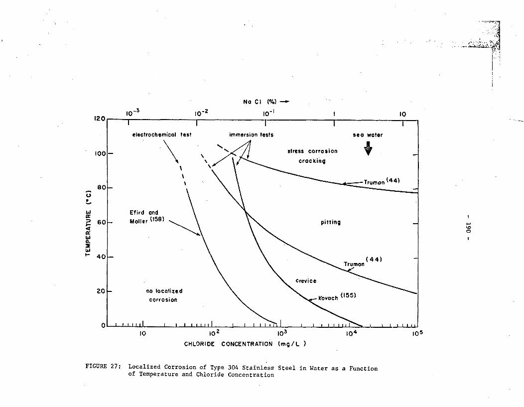
i- z:II �II
II
No Cl (%) -
10-2 10O I 1o
U
ICJ
I--
0O
105
CHLORIDE CONCENTRATION (mg/L )
FIGURE 27: Localized Corrosion of Type 304 Stainlessof Temperature and Chloride Concentration
Steel in Water as a Function
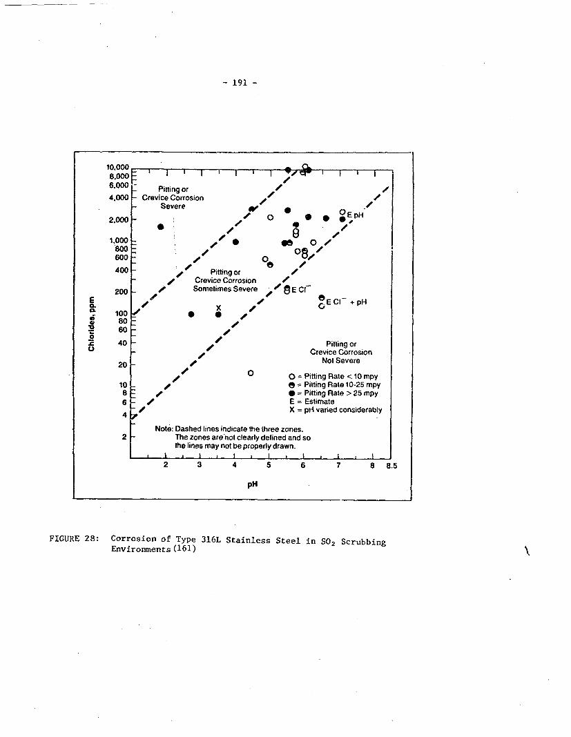
- 191 -
10.0008,0006.000 -
4.000 _
2.000
I I I
Pitting orCrevice Corrosion
Severe
I I O c I I I I
4- /
so 0 .*08,'/6
.
1,000800600
400
4-4-
/e200 _-
Pitting or /Crevice Corrosion 4Sometimes Severe - 13 E Cl
x /Ea.
10
-0
.U
E CI- +pH1008060
40
* U4/
//
4-Pitting or
Crevice CorrosionNot Severe
20 _4-
/0
1086
4
0 = Pitting Rate < 10 mpye = Pitting Rate 10-25 mpy* = Pitting Rate > 25 mpyE = EstimateX = pH varied considerably
2Note: Dashed lines indicate the three zones.
The zones are not clearly defined and sothe lines may not be properly drawn.
I * I I * I I I . I. . . . . . . . . . .
2 3 4 5 6 7 8 8.5
pH
FIGURE 28: Corrosion of Type 316L Stainless Steel in SO2 Scrubbing
Environments (161)
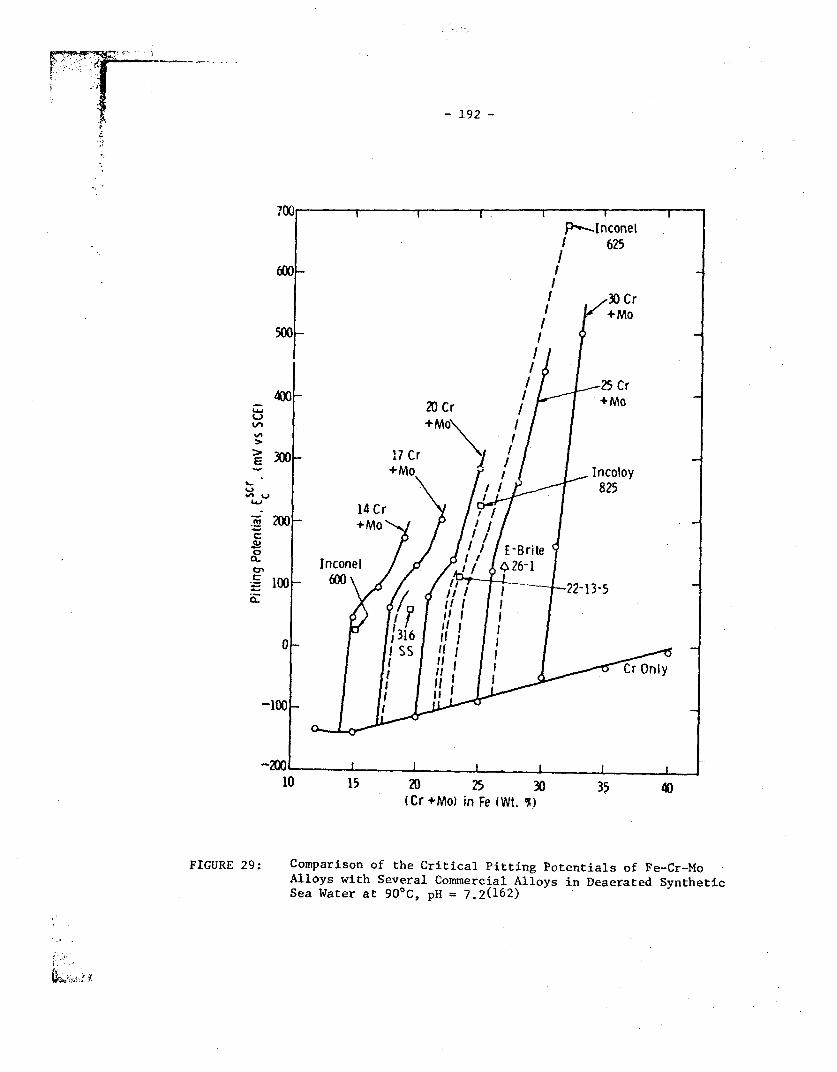
- 192 -
I.^trfvl-
>
u
I-
6.1
._
._
p-.Inconel625
600 l
I 30 Cr+MO
500I
400 - ~ ~ ~ ~ ~~I25 Cr400 20 Cr |MO
300 17 Cr ] | nc|+Mo Incoloy
ii ~~~825
14 Cr200 +MO '
20 V /E-BriteInconel / i 426-1
10 600 - 22-13-5
b~~~~~~~~~~~~of0
-100
.200 L
-
10 15 20 25(Cr+Mol inFe
30(Wt. O)
35 40
FIGURE 29: Comparison of the Critical Pitting Potentials of Fe-Cr-Mo -
Alloys with Several Commercial Alloys in Deaerated Synthetic
Sea Water at 900C, pH = 7.2(162)
I- "'.

193-
700 .
600(
I ~~~~~~~~~~~~~30 CrI6 +MO
500
25 Cr
4 00 +MtOj Atck:4 ~~~~~ ~~20 Cr
+MO 1h I
., . 30 17Cr '
c 2(JO _ +~~iMo j 247/-rt .. -+MO % Sl 6tight Crevice14C r- '?>1 Attack andlor S PiAttacki-200 . - f 14 Cr-M ot No Pitting
O~~~~M -5 I % t__ ;_ ,,
a 5~~~~~~~~2 4 E-Britt %
InconeIlt~% ~~~~~~~~~light
E£ 100 600'61 od aeCrvc Crevice anoderaterevice Attack, ardorAttack and/orPitn
Pitt- ~ . iti0 Ss 40.
Severe Crevice Attack and/or Pitting0
-100
-200! I -- I -
10 15 20 25 30 35 40(Cr +Mo) in fe (Wt. %I
FIGURE 30: Relationship Between the Critical Pitting Potentials (E scrmeasured in deaerated synthetic seawater at 900C, pH = S.2)of Fe-Cr-Mo Based Alloys and Their Resistance to Crevice;ttAck: after a 14 Day Exposure-to Synthetic Seawater at 1210Cand 960p Pg/L Oxygen. The numbers associated with individualpoints indicate the weight losses expressed in g x 10 4 afterthe 121°C exposure for samples with initial weights of -u1 g(16 2)

v
- MI I,
ZOi 40X3w
a 00
0
0
w0
0
-5
ko
3 4 5 6 7 8MOLYBDENUM CONTENT (wt%)
FIGURE 31: Crevice Corrosion Temperatures Versus Molybdenum Content forExperimental and Commercial Stainless Steels, Determined withRubber Crevices in 1 noz Forl (164)

- 195 -
8 9 10 Il iti? 13 14 15 16, I , , ,- f , , 2,7
! I2
-2 -1 0 1 2 3 4 5
FIGURE 32: Potential-pH Equilibrium Diagram for the System Nickel-Water,at 250C (127)

4 - 196 -
ZI0a'a,
Co
I
a
b
* stress coryosi aacking SCC is observed freQentty
hrgh after short testing tirres, or* significant SCC service failure have occured
* SCC has been observed iepeatedly, ormedium 0 SCC has been rePmduced in different investigations,
* bng testing tires or very high stesses may oe required
* SCC has been observed at least once , butlow * SCC incidents in service or hi the laboratory are rare
* SCC observatwis conflict with ccr-,'irnp reportsof itmunity
immune 0 SOC has been ivestigated , but so farto SCC has neither been observed in service
SWC nor in the laboratory
weight - percent nickel -
0 10 20 30 40 50 60 70 8C
OSC of Fe-Ni-Cr alloys,
high boiling MgCI 2solution, 154'Cg X_ ~~~~~Ookiuton or mill annealeda x ~~~~~~ohw terh~erture anneaead
medium
low 0
irnmuneto 0o- o
A I C.
I
OlU4 .J K) uu L2~ 'id MO b~uu19/10 25/20 21/u2 21142 19/52 3Q0r6 Z~U
600 allo1675 Cr/Ni
FIGURE 33: Influence of Nickcl Content on SCC Susceptibility ofCommercial Fe-Ni--Cr Alloys in Boiling MgC1 2 Solution(171)

- 197 -
Elv} -1 0 1~ 0 0I 21 4 ?5
I d _ ~ ~ ~ ~I_
lM - _ _C
X,8 ---- _
0,2 'o k , TiO T
-0,8 - -_ ---- -- ^>
-1, -2,2 ~~~~~~Ti 0
FIGURE 34: Potential-pH Equilibrium Diagram for the System Titanium-Water at 25°C (127)
2L2

/5I
0-2
N a C I No)10-1 l0
250
00
a.
CLI-
vtI-
10 5
CHLORIDE CONCENTRATION (mg /L)
FIGURE 35: Crevice Corrosion of Titanium and Its Alloys in Aqu.ieousChloride Solutions

0.
14
12
10
8
6
4
2
0
Hydrogen pickup ands Weight loss
No hydrogen pickupor corrosior, :
/Ti-50A.
No corrosion Crevice corrosion
No corrosion
/ /~~~~~~. CreviceTiCode-1 2 corrosion
___________________________________ ___________________________________ - ____________________________________ I
to
100 200 300 400Temperature OF
500 600
FIGURE 36: Effect of Temperature and pH on Crevice Corrosion of UnallcyedTitanium (Grade 2) and TiCode-12 in Saturated NaC1 Brine(72)
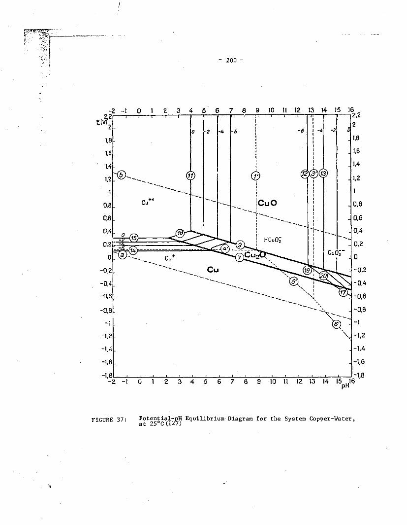
t 's
. i x
oars t ... ~~~~~~~~ 200 -
6 7 8 9 10 11 12
FIGURE 37: Potential- H Equilibrium-Diagram for the System Copper-Water,

- 201 -
sattscarbonate
FIGURE 38: Pit Formed on a Copper Surface (protected by a film of Cu20)in a Hard Wateral9 U)

- 202 -
E.v.(Sce)
5 6 7 8 9 10 11 12
FIGURE 39:
pH
The Influence of External Potential on the Potential and pHCliaracteristics of a Crevice on 90-10 Cu-Ni. The numbersindicate simultaneous data for the crevice and the externalsurface. The intersection of the general corrosion regionand the primary passivation line is circled for reference(i92)

I
- 203 -
a
a:
4r0
00
Dissolved Oxygen, ppb
FIGURE 40: Effect of Dissolved Oxygen in(Seawater on the Corrosion Rateof Copper Alloys (193)

L..
C-)
!a
a.w
LLJ
I.-
LIIU,
I
-2.5 0 10 20 30 40 50FeCI 3 CREVICE CORROSION TEMPERATURE (OC)
FIGURE 41: Results of Seawater Exposures of Austenitic Stainless Steel ShowingMaximum Seawater Temperature and FeCl3 Crevice Corrosion Temperature(CCT) for Each Coupon. Predictions of seawater performance fromFeC13 CCT's are indicated: points to the right of the hatched lineshould be crevice corrosion free (seawater too cold) and points tothe left should shnw erpuifra orn -4- ---- - - -
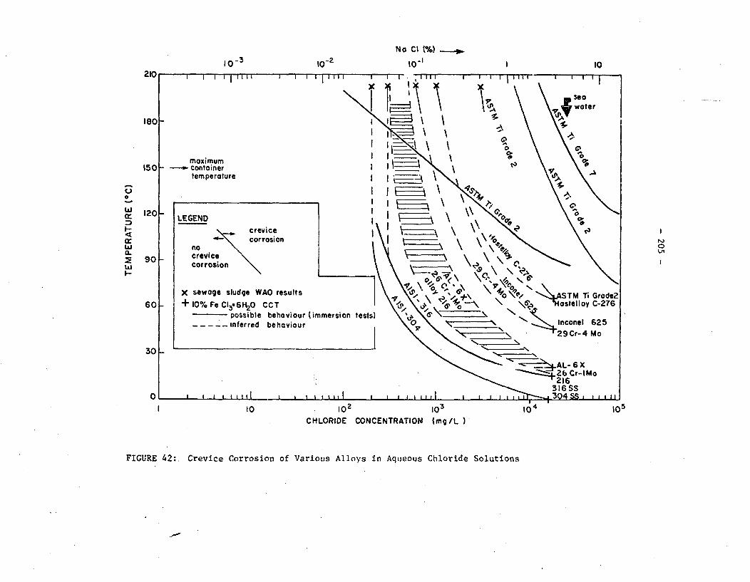
N o C I (**) lo
t0- Ii0r 2I l0
0
w
I-
wa..LI
INVi
CHLORIDE CONCENTRATION (mg/L )
FIGURE 42:. Crevice Corrosion of Various Alloys in Aqueous Chloride Solutions
Top Related