


Languages
Pages
Legal

Advanced Accelerator R&D: Flat Beam Transform & Emittance Exchange
Kwang-Je Kim ANL & U of C
June 27, 2008
ANL-UChicago-FNAL Collaboration Meeting at Fermilab

2ANL-UChicago-FNAL Collaboration Meeting, June 27, 2008
Emittance Exchange and Flat Beam Transform Emittance Exchange (EEX): Complete exchange between x- and z-phase spaces: (x,z) (z,x)
Flat Beam Transform (FBT): Transform a round photo-cathode beam to a flat beam with a desired emittance ratio in (x,y) phase space
Applications often require a combination of these manipulations

3ANL-UChicago-FNAL Collaboration Meeting, June 27, 2008
Flat Beam Transform Produce angular-momentum dominated beam and remove correlation
– R. Brinkmann, Y. Derbenev, and K. Floettmann (1999, 2001)
Experimentally demonstrated at A0– D. Edwards, et. al., emittance ratio of 40 at Fermilab A0 (Linac2000,
PAC2001)
– Yin-e Sun, U of C thesis (2005)
– Ph. Piot, Y.-e. Sun, and KJK, emittance ratio>100 (PRSTAB 9, 031001, 2006)

4ANL-UChicago-FNAL Collaboration Meeting, June 27, 2008
Emittance Exchange Scheme First dogleg provides dispersion at deflecting cavity. The cavity reduces the momentum spread of the beam and gives
a shear deflection to the beam. The second dogleg finishes the exchange. The scheme improves on the previous approximate scheme by
Cornacchia and Emma in which the second dog-leg is reversed.
final e- bunch
Initial e- bunch
x < z
D1
x > z
D2 D3
D4
3.9 GHz TM110
Diagram by Tim Koeth.

5ANL-UChicago-FNAL Collaboration Meeting, June 27, 2008
Improve HG X-Ray FEL Performance(P. Emma, Z. Huang, P. Piot, KJK)
Electron bunch emittance of current X-ray FEL projects is (xymwith Q=1 nC
This is about 10 times larger than ideal (to match the x-ray beam phase space)
Due to small energy spread, can make zm
FBT: (xy, zmExchange x & z (xy, zm
Q=30 pC, z=10 fs
• Higher gain
• Lower K
• Lower E-energy
6ANL-UChicago-FNAL Collaboration Meeting, June 27, 2008
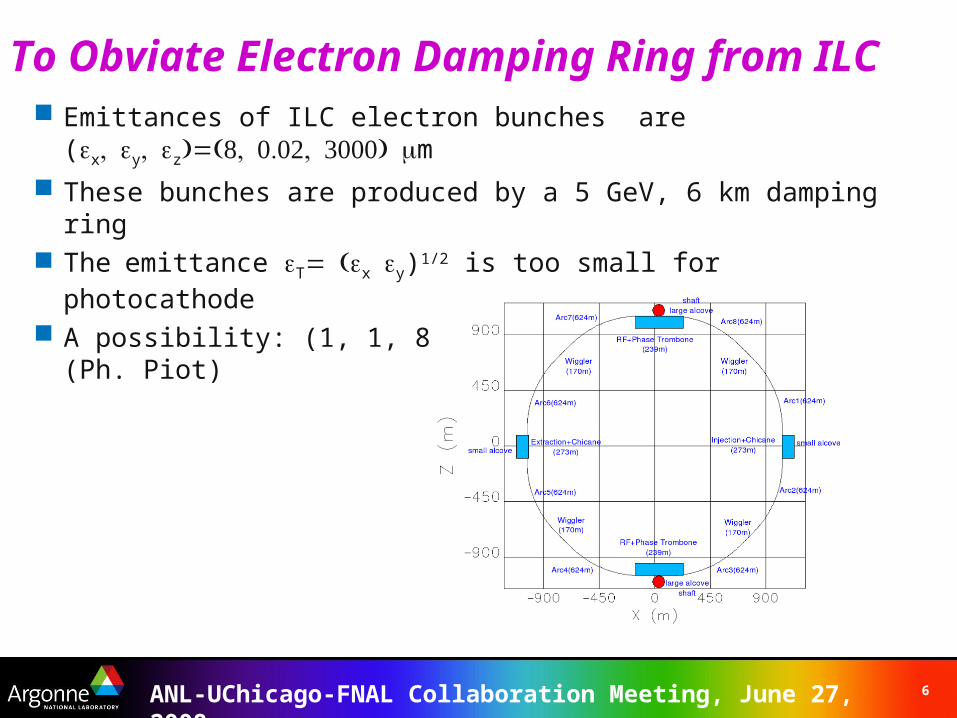
To Obviate Electron Damping Ring from ILC Emittances of ILC electron bunches are
(xyzm
These bunches are produced by a 5 GeV, 6 km damping ring Theemittance Txy)1/2 is too small for photocathode
A possibility: (1, 1, 8)(50,0.02, 8)(8, 0.02,50) (Ph. Piot)
7ANL-UChicago-FNAL Collaboration Meeting, June 27, 2008
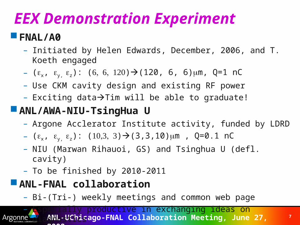
EEX Demonstration Experiment FNAL/A0
– Initiated by Helen Edwards, December, 2006, and T. Koeth engaged
– (x, y, z): ()(120, 6, 6)m, Q=1 nC
– Use CKM cavity design and existing RF power– Exciting dataTim will be able to graduate!
ANL/AWA-NIU-TsingHua U– Argone Acclerator Institute activity, funded by LDRD
– (x, y, z): ()(3,3,10)m , Q=0.1 nC
– NIU (Marwan Rihauoi, GS) and Tsinghua U (defl. cavity)– To be finished by 2010-2011
ANL-FNAL collaboration– Bi-(Tri-) weekly meetings and common web page– Especially productive in exchanging ideas on diagnostics
8ANL-UChicago-FNAL Collaboration Meeting, June 27, 2008
A0 People Helen Edwards – The Boss
– Don Edwards Ray Fliller (The Manager) Yin-e Sun (Recently from ANL) Jinhao Ruan – Laser, All things optical Jamie Santucci – Operations Tim Koeth – Rutgers Ph.D. Student Artur Paytan – Yerevan U. Ph.D. Student Mike Davidsaver – UIUC staff, controls Grigory Kazakevich – Guest Scientist, OTRI Manfred Wendt – Instrumentation, BPMs Randy Thurman-Keup – Instrumentation, Interferometer Vic Scarpine – Instrumentation, OTR and cameras Alex Lumpkin – Instrumentation, Radiation Diagnostics (On leave from ANL) Ron Rechenmacher – CD, controls Lucciano Piccoli – CD, controls Gustavo Cancelo – CD, Low Level RF Wade Muranyi – Mechanical Support, Lead Tech. Many Others from AD/RF, AD/MS

9ANL-UChicago-FNAL Collaboration Meeting, June 27, 2008
Use a 3.9GHz, 5 cell copper cavity based on the CKM SRF deflecting cavity cooled with liquid N2.
An 80 kW klystron is available.
A0 Photoinjector Layout with EEX beamline
EEX at FNAL-A0
DipolesVertical Spectrometer
3.9 GHz TM110 (deflecting mode) Cavity

10ANL-UChicago-FNAL Collaboration Meeting, June 27, 2008
First Deflected Beam by a CKM type Cavity
Operating phase for exchange

11ANL-UChicago-FNAL Collaboration Meeting, June 27, 2008
Recent Measurements at A0( Tim Koeth)
TM110 cavity strength, ko
Vary cavity strength
record vertical BPM reading
Intro p from 9-Cell
OFF73%90%100%105%
Verti
cal B
eam
Pos
ition
aft
er
Verti
cal S
pect
rom
eter
(mm
)
As the cavity strength is increased, the momentum change after the exchange line is reduced
1. Change the input momentum (0.70% Increments)2. Measure the vertical offset after exchange line spectrometer3. Increase Deflecting Cavity Strength

12ANL-UChicago-FNAL Collaboration Meeting, June 27, 2008
Diagnostics for A0 EEX Prior to the exchange :
– OTR screens for beam spot size measurement
– Slits for uncorrelated beam divergence measurement• Combined with above gives a transverse emittance measurement
– Horizontally bending spectrometer for energy and energy spread measurement
– Streak Camera for bunch length
After the exchange:– Same diagnostics for measuring transverse emittance
– Vertically bending spectrometer for momentum spread• Allows us to decouple the momentum spread measurement from any
residual horizontal dispersion from the doglegs
– Martin-Puplett interferometer for bunch length measurement• Also the streak camera (> 1 ps)

13ANL-UChicago-FNAL Collaboration Meeting, June 27, 2008
Recent Measurements at A0 ( cont’d)A preliminary measurements of several of EEX matrix elements:
Onto an attempt to directly measure the exchange:
x [mm.mrad] z [mm.mrad]
INPUT 6 120
OUT (TM110 OFF) -- 188
OUT (TM110 ON) -- 50.5
Output energy spread measurement
Bunch length measurement with a streak camera.(A. Lumpkin)
TM110 Cavity OFF
TM110 Cavity ON
Resulting emittances values:
Close to CSR increased emittace (R. Fliller)
14ANL-UChicago-FNAL Collaboration Meeting, June 27, 2008
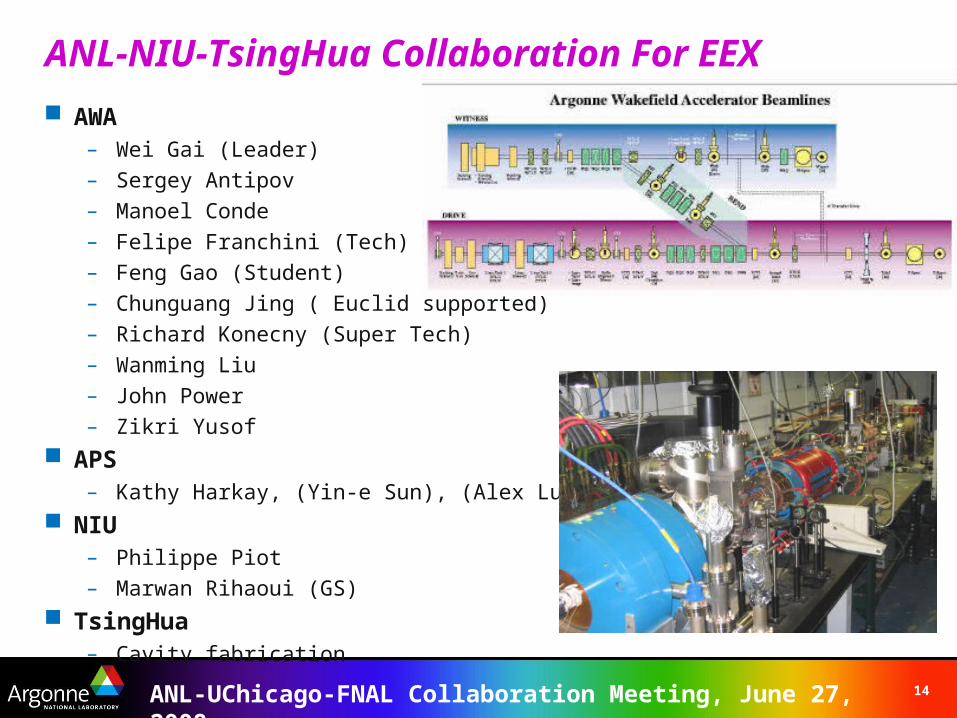
ANL-NIU-TsingHua Collaboration For EEX
AWA– Wei Gai (Leader)– Sergey Antipov – Manoel Conde– Felipe Franchini (Tech)– Feng Gao (Student)– Chunguang Jing ( Euclid supported)– Richard Konecny (Super Tech)– Wanming Liu– John Power– Zikri Yusof
APS– Kathy Harkay, (Yin-e Sun), (Alex Lumpkin)
NIU– Philippe Piot– Marwan Rihaoui (GS)
TsingHua– Cavity fabrication

15ANL-UChicago-FNAL Collaboration Meeting, June 27, 2008
Emittance Exchange (EEX) at the Argonne Wakefield Accelerator
Gun Linac
ICT1 GVGV
TQ1,TQ2,TQ3YAG1 YAG2 Emittance
Exchanger
x=10 my=3 mz= 3 m x= 3 m
y=3 mz= 10 m
TM110
Photoinjector
AWA photoinjector:Q=100pC; K= 12 MeV;Laser: x=y=2.5 mm; z=1.15 ps;
EEX beamline:=15 deg; x = 25 cm; k=4
Overall Goal: exchange small z for
largex with small Q
bunchesN.B. Exchanged many idea with Fermilab Emittance Exchange Group
16ANL-UChicago-FNAL Collaboration Meeting, June 27, 2008
Diagnostics for AWA EEX ANL diagnostics will be more challenging than A0 due to small
longitudinal emittance, thus short bunch length Spot size
– OTR screens for beam spot size measurement (same as A0)
Beam divergence– pepper pot, (allows us to look at correlations, including x-y for flat beam)
Energy and energy spread before and after EEX: – Spectrometer (same as A0)
Bunch length– zero-crossing method with linac, deflecting cavity (short bunch)
– Exploring EOS ( help from Jinhao Ruan)
In addition:– Time-of-flight monitor: stripline-based phase detection
– Longitudinal phase space: linac phase scan or deflecting cavity + spectrometer

17ANL-UChicago-FNAL Collaboration Meeting, June 27, 2008
Cavity fabricated atTsinghua U in Beijing
•Trajectory offset in a deflector cavity•D. Edwards (theory), J. Power (simulation)
•Developed a theory to eliminate by adjust cavity parameters
Deflector Cavity
Deflector cavity arrives from Tsinghua U (soon)
Installation to AWA beamline (Fall, 2008)
Improved Longitudinal Emit Measurement with deflector cavity + Spectrometer

18ANL-UChicago-FNAL Collaboration Meeting, June 27, 2008
NORTH
CONTROL ROOM LASER ROOM
SCALE 1:120
AWA AREA LAYOUT (present to 2010)
WITNESS GUNTEST STAND BEAMLINE
PHOTOCATHODE GUN
PREACCELERATOR(UPGRADED)
TEST SECTON
SPECTROMETER SPECTROMETER
LINAC
GUN
NIU LAB
BEING REMOVED
EEX BEAMLINE
NEW WITNESS BEAM
Top Related