


Languages
Pages
Legal

HAL Id: tel-00011926https://tel.archives-ouvertes.fr/tel-00011926
Submitted on 12 Mar 2006
HAL is a multi-disciplinary open accessarchive for the deposit and dissemination of sci-entific research documents, whether they are pub-lished or not. The documents may come fromteaching and research institutions in France orabroad, or from public or private research centers.
L’archive ouverte pluridisciplinaire HAL, estdestinée au dépôt et à la diffusion de documentsscientifiques de niveau recherche, publiés ou non,émanant des établissements d’enseignement et derecherche français ou étrangers, des laboratoirespublics ou privés.
A Middleware Approach for Dynamic Real-TimeSoftware Reconfiguration on Distributed Embedded
SystemsEtienne Schneider
To cite this version:Etienne Schneider. A Middleware Approach for Dynamic Real-Time Software Reconfiguration onDistributed Embedded Systems. Networking and Internet Architecture [cs.NI]. INSA de Strasbourg;Université Louis Pasteur - Strasbourg I, 2004. English. <tel-00011926>
N° d’ordre :
École Doctorale Sciences Pour l’Ingénieur
ULP – INSA – ENGEES - URS
THÈSE
présentée pour obtenir le grade de
Docteur de l’Université Louis Pasteur – Strasbourg I
Discipline : Sciences pour l’Ingénieur
(spécialité Informatique)
par
Etienne Schneider
A Middleware Approach for Dynamic Real-Time Software
Reconfiguration on Distributed Embedded Systems
Soutenue publiquement le 3 décembre 2004
Membres du jury
Directeur de thèse : M. Uwe Brinkschulte, professeur, Université de Karlsruhe
Co-Directeur de thèse : M. Bernard Keith, professeur, INSA Strasbourg
Rapporteur interne : M. Pierre Colin, professeur, ENSPS
Rapporteur externe : M. Andreas Polze, professeur, HPI – Université de Potsdam
Rapporteur externe : M. Chris D. Gill, professeur, Université Washington Saint Louis
Examinateur : Mme Aurélie Bechina, maître de conférence, Université d’Oslo
LIIA N° de l’Unité: ERT N°9


Abstract
Dynamic software reconfiguration is a useful tool to adapt and maintain software systems.
In most approaches, the system has to be stopped while the reconfiguration is in progress.
This is not suitable for real-time systems. Timing constraints must be met even while the
system is reconfiguring.
Our approach is based on the real-time middleware OSA+. Our main objective is to be able
to reconfigure one (or more) service during the run-time, with a predictable and predefined
blackout time (the time the systems does not react due to the reconfiguration).
Three different approaches concerning the blocking or non-blocking state of a service are
presented. These approaches can be used to realize a tradeoff between the reconfiguration
time and the blackout time.


Résumé
La reconfiguration dynamique d'un logiciel peut être un auxiliaire utile pour adapter et
maintenir des systèmes informatiques. Dans la plupart des approches, le système doit être
interrompu pour que la reconfiguration puisse être exécutée. Cette interruption ne peut
convenir aux systèmes temps-réel : il est nécessaires que les contraintes temporelles soient
respectées, même lorsque le système est en train d'être reconfiguré.
Notre approche se base sur OSA+, un middleware temps-réel. Notre objectif principal est
d'être capable de reconfigurer un (ou plusieurs) service lorsque le système est en fonction,
avec un temps de non-réponse prévisible et prédéfini, c'est-à-dire un temps pendant lequel
le système ne réagit pas à cause de la reconfiguration.
Trois approches différentes concernant le blocage ou le non-blocage d'un service sont
présentées. Ces approches peuvent être utilisées pour réaliser un compromis entre le temps
de reconfiguration et le temps de non-réponse.


Acknowledgments
Despite the PhD work is a personal work, it is not something, which was possible for me to
do alone.
This four-year work requires knowledge that was out of my domain before starting this
research. I came to Karlsruhe to make a PhD thesis about a reconfigurable middleware in
real-time. Before starting the research, I knew nothing about either reconfiguration, or
middleware or real-time. I will not say that I know everything about these domains, but I
know a lot more than before, especially for someone who did not start his studies as a
computer scientist. Though I still do not master them, the task will be vain and unrealistic; I
have a better understanding of many of their mechanisms.
This research work was only possible with the presence and the help of very special
persons:
- Professor Brinkschulte: man of great understanding, comprehension and support. He is the lead of the laboratory. If he would not have been there, I think the thesis will never be finished due to desperation and sometimes lack of self confidence from me. I consider him more as a mentor than anything else.
- Florentin Picioroagă: my friend and colleague, who was always there to help my poor object programming knowledge, especially for some trivial and basic questions.
- Dr. Bechina: for her support and to have introduced me in the laboratory.
Like mentioned above, the PhD is a four-year work. In four years, a lot of event can
happen in the life of someone. I came to Karlsruhe for research, but I found more than
that… It is common to say that the last months of a thesis are hard for the PhD candidate,
in my case; I think it was more that what I could have expected. However, now, I am a
brand and proud new father of my newborn son, Ryan (22nd of October 2004).

It is not possible to not mention my parents who helped me to build myself. I am certainly
not the best student, but I hope that I succeeded to be a good son and an honest person, if
I did it is thanks to them.
At last, but not least, for the last three years, nearly four now, my wife was always present
beside me, in pain, desperation but also, and more often, in the moment of happiness and
joy. She is my balance and my counterpart, without who I do not see any future.

Thanks
In addition to the persons already mentioned in the Acknowledgement part, thanks go to
Professor Keith from Strasbourg who is the co-director of this thesis work. The reviewers
of this manuscript were of a great help to finalize it with their critics, comments and
advices: Professor Polze, from the University of Potsdam, Professor Gill from Washington
University in Saint-Louis and Professor Colin from the University Louis Pasteur of
Strasbourg. I would also thank Professor Ungerer from the University of Augsburg for his
opinion and comments.
These thanks will not be complete without thank Gabi Ansorge, the secretary of the
laboratory, who was and is very helpful concerning the German language and the
administration tasks and others. Moreover, special thanks to Mathias Pacher and Stefan
Gaa, students of Professor Brinkschulte, who bring humor to the laboratory, even when
there are clouds outside.


Table of Contents
ABSTRACT .............................................................................................................................................. 3
RÉSUMÉ.................................................................................................................................................. 5
ACKNOWLEDGMENTS........................................................................................................................ 7
THANKS .................................................................................................................................................. 9
TABLE OF CONTENTS....................................................................................................................... 11
CHAPTER 1 INTRODUCTION AND MOTIVATIONS................................................................. 1-15
1.1 DEFINITIONS .................................................................................................................................................... 1-16 1.1.1 Middleware ........................................................................................................................................... 1-16 1.1.2 Real-time .............................................................................................................................................. 1-18 1.1.3 Embedded System ................................................................................................................................. 1-20 1.1.4 Reconfiguration...................................................................................................................................... 1-20 1.1.5 Reconfiguration and Real-Time.............................................................................................................. 1-21
1.2 MOTIVATIONS AND OBJECTIVES.................................................................................................................... 1-23
CHAPTER 2 STATE OF THE ART ................................................................................................. 2-27
2.1 GENERAL CONCEPTS AND TERMINOLOGY ................................................................................................. 2-27 2.1.1 Object Management Architecture ........................................................................................................... 2-27 2.1.2 CORBA.............................................................................................................................................. 2-27 2.1.3 Distributed ORBs................................................................................................................................. 2-27 2.1.4 Communication Protocols....................................................................................................................... 2-28 2.1.5 Software bus.......................................................................................................................................... 2-28 2.1.6 Least-laxity first scheduling ................................................................................................................... 2-28 2.1.7 EDF scheduling.................................................................................................................................... 2-28 2.1.8 Fixed Priority scheduling ....................................................................................................................... 2-29 2.1.9 Mutexes in real-time systems.................................................................................................................. 2-29
2.2 REAL-TIME MIDDLEWARE.............................................................................................................................. 2-29 2.2.1 Real-Time CORBA............................................................................................................................. 2-30 2.2.2 DynamicTAO...................................................................................................................................... 2-31 2.2.3 OSA+................................................................................................................................................. 2-33
2.3 REAL-TIME RECONFIGURATION ................................................................................................................... 2-35 2.3.1 The CONIC system.............................................................................................................................. 2-35 2.3.2 Software configuration management ........................................................................................................ 2-38
2.3.3 Realize.................................................................................................................................................. 2-39 2.3.4 Software Architecture Reconfiguration .................................................................................................... 2-41 2.3.5 Object and Process Migration in .NET ................................................................................................. 2-42 2.3.6 The Komodo project ............................................................................................................................... 2-44
2.4 CONCLUSION .................................................................................................................................................... 2-45
CHAPTER 3 OSA+ MIDDLEWARE ARCHITECTURE ............................................................... 3-49
3.1 SERVICES AND JOBS ......................................................................................................................................... 3-49 3.2 MICROKERNEL ARCHITECTURE ..................................................................................................................... 3-52 3.3 REAL-TIME ISSUES............................................................................................................................................ 3-53
3.3.1 Core Issues............................................................................................................................................ 3-53 3.3.2 Quality of Service Control and Assessment............................................................................................. 3-54 3.3.3 Real-time memory service........................................................................................................................ 3-54 3.3.4 Event service ......................................................................................................................................... 3-55
CHAPTER 4 ARCHITECTURE, DESIGN, STRUCTURING....................................................... 4-57
4.1 BASIC CONCEPTS.............................................................................................................................................. 4-57 4.2 DETAILED PRESENTATION OF THE CASE ..................................................................................................... 4-59 4.3 DESIGN.............................................................................................................................................................. 4-62
4.3.1 Basic algorithm...................................................................................................................................... 4-63 4.3.2 Main principle....................................................................................................................................... 4-64 4.3.3 Reconfiguration of multiple services ......................................................................................................... 4-69 4.3.4 “Transfer-State” and “Switch” cooperation in multiple service reconfiguration .......................................... 4-74 4.3.5 An alternate way to deal with reconfiguration of multiple services: ............................................................ 4-76
4.4 RECONFIGURATION- AND BLACKOUT-TIME BOUNDS................................................................................ 4-76 4.4.1 Bounds for the full-blocking approach ..................................................................................................... 4-76 4.4.2 Bounds for the partial-blocking approach................................................................................................ 4-77 4.4.3 Bounds for the non-blocking approach .................................................................................................... 4-78
CHAPTER 5 IMPLEMENTATION ASPECTS............................................................................... 5-83
5.1 MICROKERNEL ................................................................................................................................................. 5-83 5.2 BUCKETCONTAINER........................................................................................................................................ 5-87 5.3 SERVICEINFO.................................................................................................................................................... 5-89 5.4 DYNAMICCON .................................................................................................................................................. 5-93 5.5 STATESERVER................................................................................................................................................... 5-95 5.6 CONCLUSION .................................................................................................................................................... 5-99
CHAPTER 6 PRACTICAL EVALUATION .................................................................................... 6-101
6.1 OVERALL PERFORMANCE ............................................................................................................................. 6-102 6.2 ADVANTAGES OF INTRODUCING THE RECONFIGURATION SERVICE .................................................... 6-104 6.3 PRIORITY EXPERIMENT ................................................................................................................................. 6-104 6.4 SUMMARY ........................................................................................................................................................ 6-108
CHAPTER 7 CONCLUSION AND FUTURE WORK ...................................................................7-109

7.1 CONCLUSION .................................................................................................................................................. 7-109 7.2 FUTURE WORK ............................................................................................................................................... 7-110
BIBLIOGRAPHY ................................................................................................................................. 111
PUBLICATIONS.................................................................................................................................. 113
VITA ...................................................................................................................................................... 115

1-15
Chapter 1 Introduction and Motivations
An application made from different parts or components, running simultaneously on
various computers, is called a distributed system. All these parts are linked to each other using
a network, which allows them to operate together to deliver services or results on requests.
When the domain about embedded systems is approached, usually, we mean a component
made from hardware and software, which are part of a bigger tool or device. On the side of
the real-time, real-time systems are generally systems with time constraints; and thus, whatever
the range is, the processes are to be complete in a predefined amount of time.
Having all this systems together is called a distributed real-time and embedded (DRE) system.
Thus, it is a system, which is distributed across a network of small electronic components;
each one is made with, at least, a microcontroller, which forms a bigger device, for example
like a robot: there are various members, like leg or arm, communicating together towards a
common goal.
Often the DRE systems are seen in aerospace and defense activity. But they appear more
often in the medical field, where the time constraints and the accuracy are very critical too.
The middleware is used more and more to ease the management and the development of the
DRE system. In [1], the author states that middleware is very useful if not necessary in the
development of DRE systems, because middleware has essential qualities and Quality of
Service which are important for DRE systems. New applications introduce restrictions in
power consumption, heat, costs or available resources thus leading to very small
microcontrollers becoming more and more important in the field of distributed real-time
computing. Traditional middleware architectures are not well suited to support such small
devices.
Dynamic Reconfiguration deals with the changes of a working system, which, most of the time,
for various reasons, cannot be stopped. These changes can be due to the life cycle of the
system, or it can be due to failure of the system. From [2], dynamic reconfiguration occurs when
it is needed to modify the configuration of an application while it is running. But, in general,

Chapter 1 - Introduction and Motivations
it is not necessary that the application should be a long running one. It is important for the
concept that we mean modifying the configuration of a system while it is running, without
considering the needed amount of up time. Configuration changes can be done, for
example, when a new part of the software has to be added to the system, or when one has
to be replaced by a newer version, or, again, when a part of it is failing, and it needs to be
replaced by a working one.
This chapter will briefly present our motivations to bring dynamic real-time reconfiguration
to the middleware for embedded systems. In a first section we will define the important
terms and concepts, which are used later in this thesis. Then we will speak about Dynamic
Reconfiguration itself, in our case: OSA+. This acronym stands for Open System
Architecture - PLatform for Universal Services.
1.1 Definitions
1.1.1 Middleware
The word middleware is considered as a trend currently. Wherever you look in the computer
science domain, probabilities are high that you will find something named middleware.
The origins of the middleware seem nearly as old as the computer science itself, when
programmers started to make functions. Then, to reuse them, they assembled them into a
library. Moreover, since there were more and more specialized libraries, these ones were put
into specialized Software Development Kits (SDKs). Sometimes, the SDKs are very
specialized, and to use them, one will find an application skeleton; these very specialized
SDKs are named middleware. A middleware is not an application, but a software tool, which is
used to ease the design and development of applications.
Middleware in computing terms is used to describe a software agent acting as an
intermediary, between different components in a transactional or other distributed process.
The classic example of this is the separation which is attained between the client user and
the database in a client/server situation.
Researchers and developers found that introducing middleware in such a situation helps to
better service client requests by reducing the amount of connections, since they are always
resource consuming, to the database and more efficiently passing the requested data back.
Examples of proprietary transaction-management middleware software include IBM
1-16

Chapter 1 - Introduction and Motivations
Websphere[3], Tuxedo[4], ColdFusion [5]. The ObjectWeb consortium[6] is the first world-
wide consortium focused on open-source middleware.
Another reason to use middleware is to provide high-level abstractions and services to
applications to ease application programming, application integration, and system
management tasks. In this sense, middleware moves beyond transaction management and
other lower-level services to encompass database management systems, web servers,
application servers, content management systems, and similar tools that support the
application development and delivery process.
In our case, middleware has to be seen in the domain of interoperability. It is connectivity
software [7]. It allows, usually, several processes to run on one or several machines, and
interact across a network. Middleware can help the migration of applications from
monolithic heavy systems, like mainframes, to the client/server application, providing
communication across heterogeneous platforms.
The most common middleware initiatives are Open Software Foundation’s Distributed
Computing Environment[8] (also known as DCE), Microsoft’s COM/DCOM [9]
(Component Object-Model/Distributed COM, popularized thanks to the Windows
operating system) and the famous Common Object Request Broker Architecture (CORBA)
[10].
In a general way, a system with a middleware can be described like in Figure 1.
Application Application
Middleware (Distributed System Services)
Platform OS Platform OS
Figure 1. General middleware architecture.
The middleware is a kind of interface between the operating system and the distributed
applications.
Of course, since a middleware offers a wider application range, there are drawbacks due to
its concept: the maintainability of the system for example. Due to the need for long-term
1-17
Chapter 1 - Introduction and Motivations
availability of many embedded systems, it is crucial to stop the system only to maintain or to
fix bugs. Instead, it would be desirable to perform them while the system is running. This
reduces maintenance costs and improves productivity. The maintenance process might be
complex due to many components, which might be affected in a widely distributed system.
This task is essential, and a real-time middleware should support the reconfiguration
process.
The advantages of using a middleware are various. Often, and especially in our case, its aim
is a distributed system. Thus, it offers a more powerful system than just a local computer.
Moreover, as long as the network between all platforms is operational, all these platforms
can share their resources thanks to the help of the middleware. A platform running an
application may migrate its tasks to another platform with a lower load for example. Real-
time middleware helps to simplify the development, operation and maintenance of such
systems. New applications introduce restrictions in power consumption, heat, costs or
available space thus leading to very small microcontrollers becoming more and more
important in the field of distributed real-time computing. Traditional middleware
architectures are not very suitable for supporting such small devices.
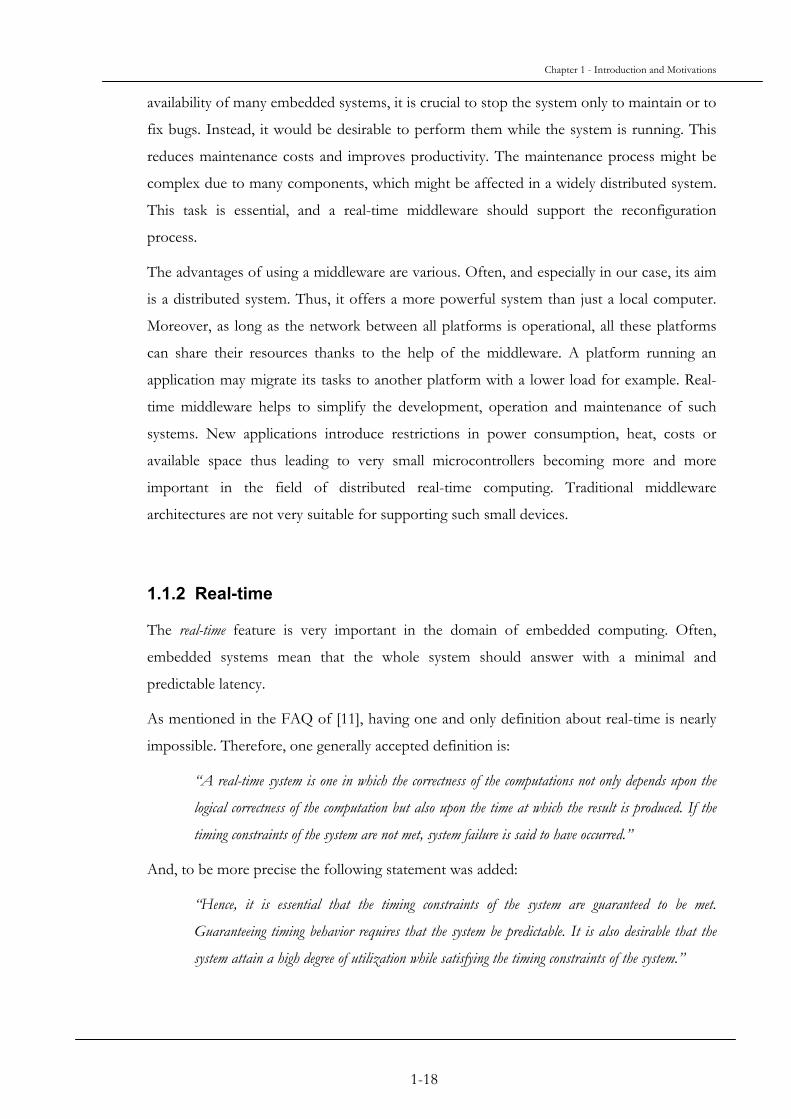
1.1.2 Real-time
The real-time feature is very important in the domain of embedded computing. Often,
embedded systems mean that the whole system should answer with a minimal and
predictable latency.
As mentioned in the FAQ of [11], having one and only definition about real-time is nearly
impossible. Therefore, one generally accepted definition is:
“A real-time system is one in which the correctness of the computations not only depends upon the
logical correctness of the computation but also upon the time at which the result is produced. If the
timing constraints of the system are not met, system failure is said to have occurred.”
And, to be more precise the following statement was added:
“Hence, it is essential that the timing constraints of the system are guaranteed to be met.
Guaranteeing timing behavior requires that the system be predictable. It is also desirable that the
system attain a high degree of utilization while satisfying the timing constraints of the system.”
1-18
Chapter 1 - Introduction and Motivations
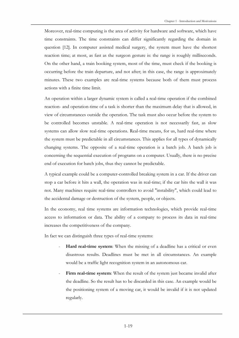
Moreover, real-time computing is the area of activity for hardware and software, which have
time constraints. The time constraints can differ significantly regarding the domain in
question [12]. In computer assisted medical surgery, the system must have the shortest
reaction time; at most, as fast as the surgeon gesture is: the range is roughly milliseconds.
On the other hand, a train booking system, most of the time, must check if the booking is
occurring before the train departure, and not after; in this case, the range is approximately
minutes. These two examples are real-time systems because both of them must process
actions with a finite time limit.
An operation within a larger dynamic system is called a real-time operation if the combined
reaction- and operation-time of a task is shorter than the maximum delay that is allowed, in
view of circumstances outside the operation. The task must also occur before the system to
be controlled becomes unstable. A real-time operation is not necessarily fast, as slow
systems can allow slow real-time operations. Real-time means, for us, hard real-time where
the system must be predictable in all circumstances. This applies for all types of dynamically
changing systems. The opposite of a real-time operation is a batch job. A batch job is
concerning the sequential execution of programs on a computer. Usually, there is no precise
end of execution for batch jobs, thus they cannot be predictable.
A typical example could be a computer-controlled breaking system in a car. If the driver can
stop a car before it hits a wall, the operation was in real-time; if the car hits the wall it was
not. Many machines require real-time controllers to avoid "instability", which could lead to
the accidental damage or destruction of the system, people, or objects.
In the economy, real time systems are information technologies, which provide real-time
access to information or data. The ability of a company to process its data in real-time
increases the competitiveness of the company.
In fact we can distinguish three types of real-time systems:
- Hard real-time system: When the missing of a deadline has a critical or even
disastrous results. Deadlines must be met in all circumstances. An example
would be a traffic light recognition system in an autonomous car.
- Firm real-time system: When the result of the system just became invalid after
the deadline. So the result has to be discarded in this case. An example would be
the positioning system of a moving car, it would be invalid if it is not updated
regularly.
1-19

Chapter 1 - Introduction and Motivations
- Soft real-time system: when the deadline can be missed to a given extent. An
example can be video or audio streams.
1.1.3 Embedded System
Embedded Systems are, usually, sets of both hardware and software parts, which form
components of some larger system or systems and which are expected to function without
human action. A typical embedded system consists of a single-board microcomputer with
software in a ROM, which starts running some special purpose application program as soon
as it is turned on and will not stop until it is turned off (if ever). Thus the requirements of
an embedded system differ from the ones of a general purpose computer.
An embedded system may include some kind of operating system but often it will be simple
enough to be written as a single program. It will not usually have any of the normal
peripherals such as a keyboard, monitor, serial connections, mass storage, etc. or any kind
of user interface software unless these are required by the overall system of which it is a
part. Often an embedded system must provide real-time response. Embedded systems are often
regrouped to form larger devices.
A key factor for producing embedded systems is to minimize the costs, but the safety and the
predictability are important too. They are often produced in more than tens of thousands,
so for the manufacturer it is very important to reduce costs and to have minimal power
consumption. That is why the processors and the memory are respectively slow and small.
Moreover, the boards are usually simplified compared to general purposes computer to
improve efficiency while minimizing the need for extra components.
Programs on an embedded system often must run with real-time constraints with limited
hardware resources: often there is no disk drive, operating system, keyboard or screen.
Instead of a mechanic disk drive, a flash drive replaces the magnetic but fragile disk. A small
keypad and LCD screen may be used instead of a PC keyboard and screen.
1.1.4 Reconfiguration
The term reconfiguration means the possible changes for a configuration. Generally speaking,
a configuration is the current environment of an object. During the lifetime of an object, its
environment may change, and thus, the object may have to adapt to continue its actions.
1-20

Chapter 1 - Introduction and Motivations
In computer science a system configuration is made from software components and hardware
components. Changes can occur on both levels, and may need adaptation of the software to
pursue its task.
Static configuration is generally a configuration of a system which once it is set will not change
over time, or if it has to be modified the system has to be stopped. Often a static
configuration is used for small devices which have only one single task. The maintenance of
such a static configuration is eased by the size of the system, and by its relative simple
complexity.
On the other side, dynamic configuration is used for more complex devices or systems. These
systems or devices are made from various smaller components, which should interact
together to realize one goal. The application of a dynamic configuration often concerns
distributed systems, which cannot be stopped to modify the behavior of one of their
components. The realization of a dynamically reconfigurable system is more complicated
than one relying on a static configuration for different reasons, among them:
- the complexity of the whole system depends on various software and hardware
components;
- the changes are to be applied during the runtime of the system,
- since the changes occur when the system is running, the components of the system
will have different states during runtime, and thus these states will have to be
preserved during the reconfiguration,
- processes on the system may have deadlines, which have to be respected, thus the
real-time feature of the system is another constraint.
In [13], the authors say that, most of the time, it is difficult to foresee all changes, which can
happen on a system. It is why dynamic reconfiguration is important for a complex system.
1.1.5 Reconfiguration and Real-Time
In embedded systems, real-time is one of the key factors for reliability. Embedded systems
can be composed of various sub-systems or devices. To manage together these
components, distributed systems are often used.
This leads us to the main problem: how, since embedded devices often have limited
resources, is it possible to reconfigure such embedded systems in limited time and space?
1-21
Chapter 1 - Introduction and Motivations
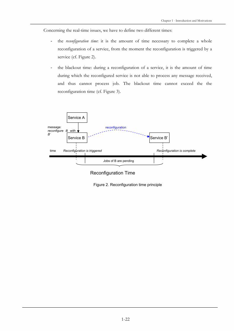
Concerning the real-time issues, we have to define two different times:
- the reconfiguration time: it is the amount of time necessary to complete a whole
reconfiguration of a service, from the moment the reconfiguration is triggered by a
service (cf. Figure 2).
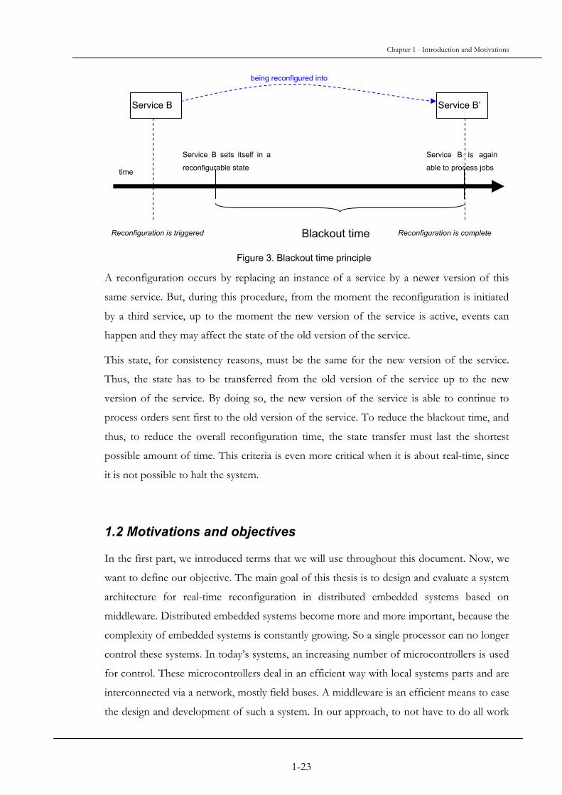
- the blackout time: during a reconfiguration of a service, it is the amount of time
during which the reconfigured service is not able to process any message received,
and thus cannot process job. The blackout time cannot exceed the the
reconfiguration time (cf. Figure 3).
Service B
reconfiguration message: reconfigure B with B’
Reconfiguration is triggered
Jobs of B are pending
Reconfiguration is complete
Service B’
time
Service A
Reconfiguration Time
Figure 2. Reconfiguration time principle
1-22
Chapter 1 - Introduction and Motivations
being reconfigured into
Service B Service B’
Service B is again
able to process jobs
Service B sets itself in a
reconfigurable state time
Blackout timeReconfiguration is triggered Reconfiguration is complete
Figure 3. Blackout time principle
A reconfiguration occurs by replacing an instance of a service by a newer version of this
same service. But, during this procedure, from the moment the reconfiguration is initiated
by a third service, up to the moment the new version of the service is active, events can
happen and they may affect the state of the old version of the service.
This state, for consistency reasons, must be the same for the new version of the service.
Thus, the state has to be transferred from the old version of the service up to the new
version of the service. By doing so, the new version of the service is able to continue to
process orders sent first to the old version of the service. To reduce the blackout time, and
thus, to reduce the overall reconfiguration time, the state transfer must last the shortest
possible amount of time. This criteria is even more critical when it is about real-time, since
it is not possible to halt the system.
1.2 Motivations and objectives
In the first part, we introduced terms that we will use throughout this document. Now, we
want to define our objective. The main goal of this thesis is to design and evaluate a system
architecture for real-time reconfiguration in distributed embedded systems based on
middleware. Distributed embedded systems become more and more important, because the
complexity of embedded systems is constantly growing. So a single processor can no longer
control these systems. In today’s systems, an increasing number of microcontrollers is used
for control. These microcontrollers deal in an efficient way with local systems parts and are
interconnected via a network, mostly field buses. A middleware is an efficient means to ease
the design and development of such a system. In our approach, to not have to do all work
1-23

Chapter 1 - Introduction and Motivations
from scratch, we will rely on and extend an existing middleware for this purpose (see
Chapter 3) For evaluation, we will use a theoretical approach to handle time bounds
combined with measurements to examine the system performance. Our approach shall not
only allow bounded reconfiguration and blackout time but also give the possibility to define
trade-offs between the two values. Furthermore, it will be able to work on systems with
limited memory and computation resources, as is often found in embedded systems.
Application fields for such architecture would be for example:
- For autonomous aircraft, navigation can be based on different methods: radar,
GPS, landmarks, etc. Flying over ground, landmarks are a good choice for the
aircraft to precisely determine its current position. This is no longer true when flying
over water. So when crossing the coastline, a reconfiguration of the navigation
would be a resource saving way to reflect this change. Resources are normally
limited in small airplanes due to weight. Of course, the reconfiguration has to be
done in real-time so as not to crash the airplane and not to loose track. Dynamic
real-time reconfiguration can be used for other purposes in this domain too, for
example the adaptation of the analyzing routine in a surveillance plant to the current
needs.
- In the medical domain, since surgery is more and more assisted by computers, it is
possible to see reconfiguration while the surgeon is operating. For example, the
sensor and the embedded system connected to it are set for a low blood pressure,
then after cauterizing a vein the blood pressure has a normal level. Now, the first
configuration of the embedded system is not valid anymore, and it needs a
reconfiguration to handle the new environment changes. A dynamic reconfiguration
of the system will allow the surgeon to continue his operation without any
interruption, and thus, the patient will not stay longer than necessary in the
operating room.
- Dynamic reconfiguration can be used in a factory equipped with automated guided
vehicles. Assume such a vehicle is operating in a room with optical tracks on the
ground to drive the vehicle from one point to another. The vehicle is using a driving
module, which is using the optical tracks to move, when it receives a new order to
go to another place; however there is no more optical track, just the walls and some
obstacles to reach its destination. Rather than to have the light sensor and its
module still working, and thus using the batteries of the vehicle, the dynamic
1-24

Chapter 1 - Introduction and Motivations
reconfiguration will allow reconfiguring the driving module by using a laser beam,
which will detect all obstacles on the road from the vehicle up to its destination
point.
Not all of these applications are real yet, but the automated guided vehicle [14] is part of our
project at the University of Karlsruhe and it is expected to be functional by the end of
year 2005.
1-25

2-27
Chapter 2 State of the Art
2.1 General Concepts and Terminology
Before detailing the state-of-the-art, we will start this chapter with a brief introduction of
some general real-time and middleware related concepts and terminology important for our
work.
2.1.1 Object Management Architecture
The Object Management Group (OMG), a joined consortium of several companies and
research sites, aims to standardize the handling of object oriented architectures. The Object
Management Architecture or OMA created by the OMG sets up an environment to handle
distributed heterogeneous objects in a standardized way. The OMG found that applications
share a lot of common functionality. This functionality are assembled in a set of standard
objects with standard functions [15].
2.1.2 CORBA
CORBA is an acronym and means Common Object Request Broker Architecture[16]. It
defines the interface standard of the OMA. It allows applications and programs running on
different platforms and computers to interact with each others, as long as these programs
and applications respect the CORBA standard. It uses object-oriented principles
(polymorphism, inheritance, identification, etc.). CORBA is one of the most popular
middleware standards. The CORBA specifications are presented in [10].
2.1.3 Distributed ORBs
The ORB (Object Request Broker) is the core of the OMA. It is responsible to realize the
communication of the distributed objects in CORBA and to localize, identify and manage
these objects. From [17] and [18], the implementation of a CORBA based middleware is

Chapter 2 - State of the Art
built from Distributed ORBs, which reside on different platforms. This kind of middleware
replaces more and more traditional communication mechanisms and gateway objects. It
leads to the creation of heterogeneous and transparent distributed object applications.
2.1.4 Communication Protocols
Today, computers are nearly all interconnected through networks. However, the networks
are not only sets of cables and network cards; they are composed of various other elements,
which are using protocols, organized by function and level of detail. The ISO Network
Protocol Standard, a work by the IEEE and the ISO, defines all these protocols. A protocol
is a set of rules that governs how information is delivered.
2.1.5 Software bus
Generally, “bus” is a hardware term used to speak about interconnecting pathways. But, a
software bus is a programming interface, which allows programs or applications or software
modules to transfer data to each other in a standardized way. As with hardware buses,
software buses allow developers to plug in or remove components. E.g., CORBA and the
OMA can be seen as defining a software bus.
2.1.6 Least-laxity first scheduling
The laxity is the amount of time between the complete execution of a task since its start and
its next deadline. It is the size of the available scheduling window. The least-laxity first (LLF)
algorithm, as described in [19] is an optimal real-time scheduling methodology on
uniprocessor system. This means as long as the processor load is less or equal 100%, LLF
will find an executable schedule meeting all the deadlines. Furthermore, LLF is able to
detect time constraint violations ahead of reaching a tasks deadline. The main drawback of
this algorithm is excessive context switching, depending on scheduling granularity. If
multiple tasks have nearly the same laxity, LLF would have them context switch every time
the scheduler gets control.
2.1.7 EDF scheduling
Earliest deadline first (EDF) scheduling (cf. [20]) is another dynamic real-time scheduling
principle. This scheduling algorithm allows the task with the earliest deadline to be executed
first. It is a scheduling algorithm often used in hard real-time system.
2-28

Chapter 2 - State of the Art
Like LLF, EDF is an optimal scheduling scheme on uniprocessor systems. The advantage
of EDF compared to LLF is the lower overhead and less context switches.
On the downside, EDF performs worse than LLF when deadlines are missed. Under
overload conditions, LLF is the better scheduling scheme.
2.1.8 Fixed Priority scheduling
Fixed Priority (FP) scheduling is the most simple real-time scheduling scheme. Each task gets
a fixed priority. The task with the highest priority is executed. FP is not optimal. Even with
processor loads below 100%, FP might not find an executable schedule. The maximum
processor load for which n executable schedule is guarantied calculates to
n(21/n-1), where n is the number of tasks in the system (cf. [21]).
To assign fixed priorities to periodic tasks, Rate Monotonic Scheduling (RMS) is an optimal
approach. Optimal does not mean: the scheduling is optimal. As mentioned above, this is
not true for fixed priorities. Optimal means here, there is no better way to assign fixed
priorities to tasks. RMS assigns a priority reciprocally to the period of a task. The shorter
the period is, the higher is the priority (cf. [21]).
2.1.9 Mutexes in real-time systems
Mutex (Mutual Exclusion) is a standard mechanism to synchronize tasks. Only one task is
allowed to enter, the other tasks have to wait until the task possessing the mutex leaves.
In real-time systems, some additional aspects have to be observed: the priority of the task
waiting for a mutex determines the sequence of accessing the mutex. Furthermore, priority
inheritance is used to avoid priority inversion. If a high priority task is waiting for a mutex
possessed by a low priority task, this task will inherit the priority of the high priority task.
2.2 Real-Time Middleware
In this section, we present existing approaches on combining middleware with real-time
capabilities.
2-29

Chapter 2 - State of the Art
2.2.1 Real-Time CORBA
Real-Time CORBA is an enhancement of CORBA. It was designed by the Real-Time
Special Interest Group of the Object Management Group (RTSIG-OMG), with
participation of several companies in the field of the embedded systems, like Boeing and
Objective Interface for example. The Real-Time CORBA specifications [22] allow the
management of hardware resources whereas CORBA is an intermediate layer between the
operating system and the applications.
One of the key specifications is the end-to-end predictability. To reach this goal, Real-Time
CORBA supports fixed priority scheduling. This scheduling method defines static priority
levels for each thread. The priorities, despite their value at the initialization, can be modified
during their lifetime. Real-Time CORBA relies on the possibility of the operating system to
let applications specifying priorities. Another important aspect of Real-Time CORBA is
how are handled the priorities in the system and how are handled the communication
requests from the client applications up to the server application in a consistent manner, i.e.
without priority inversion, except the ones, which are expected. The priority of the client on
its operating system is mapped to an ORB’s priority. The priority is sent, as part of the
request message, up to the server. Once the server receives the message, the priority of the
client is mapped relatively with the priorities of the operating system of the server. Thus,
the priorities are treated relatively the same way on the distributed system.
RT-CORBA specifies the way the applications can interact with the available resources [23].
This includes the processor resources, the communication resources and the memory
resources. The resource management is done with the usage of standard interfaces and
Quality of Service policies, a policy should affect in the same manner each side of the end-
to-end system: the client and the server. Concerning the communications between the client
and the server, the connections can have different priorities increasing the traffic
predictability: real-time and non real-time information can exist together. The
communication protocols properties are controlled by the applications. A distributed
system containing, between the server and the client, a network, Real-Time CORBA does
not rely only on the TCP/IP protocol due to the weak predictability of the protocol and the
lack of consistent guarantee.
Thus, a Real-Time-CORBA system must guarantee the resource usage and the resource
availability for each application. This concerns the threads, the memory, the CPU, and the
communication way (like the network). Such a control over the hardware is provided
2-30

Chapter 2 - State of the Art
through open interfaces to the resources. On another side, the specification of the CORBA
enhancement gives the possibility to the application developer to define thread pools. The
shared resources of the system, with the help of the mutexes, are protected in a consistent
way. It can be difficult to predict how a system can react, moreover when it is a matter of
time prediction. One of the goals of the research group was to focus on the predictable
behavior of the system, to allow the design of schedulable and distributed systems. To be
predictable, especially for hard real-time systems, all the system components, i.e. the
transport, the real-time operating system and the object request broker must use predictable
and schedulable logic; otherwise, the real-time constraints of the system cannot be met.
Real-Time CORBA’s specifications define a global scheduling service, which allocates the
available resources to comply with QoS needs. Concerning the connections between the
client and the server, a priority can be defined by each client and for each connection.
One of the problems of the real-time embedded systems is their maintainability and their
costs. The Real-Time CORBA specifications offer the possibility to reduce drastically the
impact of issues due to the embedded system by bringing to bear the advantages of
distributed systems.
2.2.2 DynamicTAO
Motivated by the fact that the computer environment is more and more heterogeneous and
dynamic, researchers are studying the dynamic configuration of middleware.
The project named dynamicTAO[24] is characterized by being a CORBA compliant ORB. It
is based on the TAO ORB[25] due to its flexibility, portability, extensibility and the fact that
it can easily be configured. The researchers designed dynamicTAO to be reconfigurable and
reflective. This means that it can modify itself its definition and evaluation rules, and it
knows how to alter them. This self-configuration answers to the detection of the
environment change in the goal to optimize, all the time, the performance of the system.
They choose an approach to modify an existing implementation of a CORBA compliant
ORB because they consider this approach more productive than developing a middleware
from scratch. Despite TAO can barely be reconfigurable during run-time, the approach of
the researchers, named 2K, allows applications to be adaptive in a dynamic environment.
dynamicTAO is reflective because of its ability to modify or to reconfigure its own engine.
This self-configuration is done in three steps: the components of the ORB can be moved at
2-31

Chapter 2 - State of the Art
any place in the distributed system; modules can be loaded or unloaded; at last, the
configuration state of the ORB can be modified.
One of the key items of dynamicTAO is the component configurator, which acts like a
bookkeeper for the intra dependencies of the component of the system. This configurator
keeps track of the references to instances of the ORB and to the servants available in the
same process. The ORB can support different strategies like Concurrency, Security and
Monitoring. And the strategies related to the ORB can be modified during run-time as long
as the constraints are respected. In some cases, the strategies can use the configurator for
saving their dependencies related to other strategies and to the ORB. In fact, various
information can be saved in the configurator, it is depending on the strategies currently
running.
To ease the dynamic reconfiguration, the components of the system are dynamically
loadable libraries: they are used only when needed. These libraries are available to use once
they are put on the Persistent Repository where they can be manipulated. The
reconfiguration interface on dynamicTAO can be split in three interfaces:
- the Distributed Configuration Protocol Broker (DCP Broker), which is a subclass of
the Network Broker. It monitors the connection requests. Once there is a
connection request from a client, the reconfiguration process is started;
- the Reconfiguration Agent Broker is like the DCP Broker, but focuses more on the
reconfiguration of a set of ORBs;
- the DynamicConfigurator exports an Interface Definition Language interface. This
DynamicConfigurator interface defines the operations, which can be done on
dynamicTAO abstractions.
The process of reconfiguration is processed such a way: first, the implementation is loaded
into memory – in the repository – then the implementation is attached to a hook in TAO.
Once the implementation is assigned to a hook, it is possible to use it.
Replacing the implementation by another one is already a reconfiguration, but, most of the
time, the component reconfigured was computing some process before the reconfiguration
occurs. An implementation cannot be switched whenever, but it has to follow rules. E.g. the
old implementation should not be used anymore, if it is still used then the reconfiguration
has to be put on hold until it is free from any activity. Another problem concerns the state
2-32
Chapter 2 - State of the Art
information: the integrity or a part of the state information of the old component may be
needed by the new component, thus it has to be transferred to the new component.
A feature of dynamicTAO is the ability to notice when change should occur. This is ensured
by monitoring the interactions between the objects of the distributed system. Thus, by
knowing the load of the resources, the system is able to adapt to optimize its efficiency.
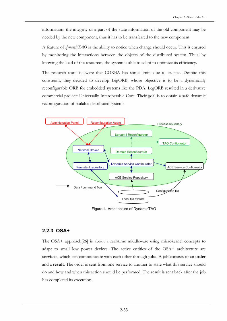
The research team is aware that CORBA has some limits due to its size. Despite this
constraint, they decided to develop LegORB, whose objective is to be a dynamically
reconfigurable ORB for embedded systems like the PDA. LegORB resulted in a derivative
commercial project: Universally Interoperable Core. Their goal is to obtain a safe dynamic
reconfiguration of scalable distributed systems
Figure 4. Architecture of DynamicTAO
2.2.3 OSA+
The OSA+ approach[26] is about a real-time middleware using microkernel concepts to
adapt to small low power devices. The active entities of the OSA+ architecture are
services, which can communicate with each other through jobs. A job consists of an order
and a result. The order is sent from one service to another to state what this service should
do and how and when this action should be performed. The result is sent back after the job
has completed its execution.
Administration Panel Reconfiguration Agent Process boundary
Servant1 Reconfigurator
Domain Reconfigurator
Dynamic Service Configurator
ACE Service Repository
TAO Configurator
Network Broker
Persistant repository ACE Service Configurator
Local file system
Data / command flow Configuration file
2-33

Chapter 2 - State of the Art
Services are plugged into a platform and can communicate with each other. Because OSA+
is intended to work in a distributed environment, there might be more than one platform.
All physical platforms work together and provide the user an overall virtual platform, which
hides the heterogeneity of the underlying communication, and operating systems.
In order to build a highly scalable architecture, which can easily be adapted to different
hardware and software environments, a microkernel architecture well known from
operating systems is used. The OSA+ platform consists of a very small core platform,
which offers basic functionality. This core platform contains no hardware or operating
system-dependent parts. The core platform uses special services to extend its own
functionality. These special services are the basic services, which are used for the
adaptation to a specific hardware and operating system environment, and the extension
services, which extend the core functionality of the platform (cf. Figure 5). It should be
mentioned here that the platform is also able to run without any extension services. Since
the research is focused on microcontrollers, it is necessary to minimize the average
overhead, because of a lack of power and memory. Thus the kernel and the basic services
should be as small as possible to meet the constraints of such a reduced system.
UserService
UserService
OSA+ Core Platform
BasicService
ExtensionServices
Adaptation to hardware, operating system and communication system
Functional extensions
… …
Figure 5: OSA+ Architecture
One application example for the OSA+ architecture is a real-time processing environment
for oil-drilling platforms. In this project (DIAGNOSIS, funded by the EU), oil drilling
2-34

Chapter 2 - State of the Art
heads are equipped with small microcontrollers to gather integrated sensor data about oil
pressure, temperature, etc. and to control actors like valves. A PC running an RT-OS
(VxWorks) collects the data from several drilling heads. Several of these PCs again are
combined to form a group and to perform vital control decisions (e.g. about opening and
closing valves) based on the sampled data. This scenario is an ideal application field for
OSA+ combining small microcontrollers with powerful PCs.
2.3 Real-Time Reconfiguration
This chapter presents approaches to handle dynamic reconfiguration in real-time.
2.3.1 The CONIC system
The researchers [13] are among the firsts, who tried to establish first ideas about dynamic
reconfiguration for distributed systems. When they first wrote about dynamic configuration
for distributed real-time systems, there was no middleware for distributed systems like
CORBA. The dynamic configuration of a system means to modify and extend a system
while it is running, without stopping it. They present with their own distributed and
dynamically configurable system, CONIC, their concepts about the requirements for a
dynamically reconfigurable system.
It is important to say that the modifications for the researchers are incremental, with all
advantages and drawbacks of this system. They consider three different kinds of
modifications:
- the planned ones, which are done under human supervision usually before being
totally automated.
- the operational changes are needed in the case of a system failure, thus replacing,
moving or removing components of the system.
- the evolutionary changes allow the system to follow modifications of its
environment.
As it is well known now, to have a large system, it is better to have it made from small
components, this will enhance maintainability, bug tracking, but it will ease the
reconfiguration. A system is a configuration of these components. To describe a
configuration, Magee and Kramer refer to a configuration language with which they write a
configuration specification. This specification gives information about the software
2-35

Chapter 2 - State of the Art
components, their instances, the connections between those instances, and the location of
those instances on the distributed system. Such distributed system specifications are divided
into three different structures: the logical structure for the software, the physical structure
for the hardware and the logical to physical mapping for the physical location of the
software components. Their research work focuses on the logical part.
Their research group was motivated to have a real dynamically reconfigurable system
especially because all other approaches forced the systems to be put off-line if it was
necessary to reconfigure them, which was all but efficient and economic. Their approach
relies on change specifications, which include modifications concerning the previous
configuration, e.g. adding new components, modifying others. To prevent any error, the
change cannot occur if its specification was not validated. A configuration manager is in
charge to translate the configuration into operating system commands. In the objective to
have a truly dynamically reconfigurable system, they define properties which are essential or
desirable to have a dynamic configuration. These properties concern the programming
language (e.g. modularity, interconnection and interfacing), the configuration and change
specification (e.g. context definition, instantiation and interconnection), the operating
system (e.g. module management, connection management, and communication support),
the validation process (e.g. interconnection, allocation and specification and system
consistency) and the configuration manager (e.g. allocation and specification and system
consistency). Having a system which fulfills all these essential properties, and then one will
have a dynamically reconfigurable distributed system. The researchers tried out and put into
application their principles, and obtained CONIC.
CONIC is a kind of programming language whose syntax is close to that of PASCAL. It is
used to describe systems with interconnected modules, a programming language and an
operating system able to support and manage CONIC systems. The modules have
interfaces (called, according to the case, exitports and entryports) where messages are
sent and received. Messages are the only way that modules can use to communicate with
each other. The modules are written such a way that the programmer will give their context
– the types used, the instances in the system and the link between the modules. The change
of configuration is done by writing a new module, which will dynamically modify the
system. If part of the running system has to be modified, then the programmer should take
care of the inverse procedure of modules creation, i.e. in spite of having use, create and
link, there will be first unlink, delete and remove. They are just the inverse functions. A
change can only be validated if all links are “unlinked” when an instance is “deleted.” Since
2-36

Chapter 2 - State of the Art
CONIC is a programming language, the way the dynamic configuration is done looks alike
programming: a module source is compiled by the CONIC compiler, which produces a
descriptor file and a code file, this one containing object code, for the target hardware.
Then, from the configuration source file concerning the system, group or changes, a
Translator will produce a descriptor file for the system or the group, which is a set of
modules. Then the CONIC Station Builder, which produces Load Image file for each
station, processes these descriptor files, with the target system description. Each station is
connected to each other, thus multicast does the communication between each station, and
the CONIC Station Builder does not include the physical connection between each station.
At last, the Dynamic Configuration Manager is responsible for handling requests to modify
the system. The configuration manager processes such requests and then produces
operating systems commands to apply the changes. Once the configuration manager
validated the changes, it updates the system descriptor file to reflect the changes of the
system.
Despite all this, the researchers did not consider the case of the state of the modules, and
they recognize that it is difficult to evaluate the consequences of a change during the
runtime of the system. Moreover, the consistency of the system is in question too after the
changes occurred. At last, they are concerned about the effect of the changes on the timing
of the system. It is interesting to notice that in that time, the configuration was considered
as an element of the programming language.
Configuration changes
Figure 6. Dynamic Configuration Process in CONIC
Validation
Configuration Manager
Configuration Specification i
Configuration Specification i+1
Operating System System i System i+1
Valid changes
commands
2-37

Chapter 2 - State of the Art
2.3.2 Software configuration management
The projects concerning SCM[27] are about software configuration management: they
include three related projects whose goals focus on SCM. More and more, the management
of software is related to the hardware because the trend is aiming at distributed systems.
More specifically, the researchers of Carleton and the Bulldog Group focus on service
components which are software components with software-based services and sometimes,
hardware-based services.
In their approach, two or more service components can be composed to form a single new
service able to be deployed for usage with new features. Their objective is to compose
service components during runtime, i.e. dynamically. They analyzed different ways to reach
their goal, but most of the time; the dynamic techniques are not present in the normal
“design and develop” procedures.
To form a composite service, there are different possibilities: first by using a composite
service interface, which regroups the composable methods of several service components,
and through which all calls to the methods are redirected to the correct component.
Second, by creating a stand alone composite service, which interconnects the service
components: the output of a service component is chained to the input of another one. At
last, the third technique is to create a stand-alone composite service made with the
assembling of all the composable methods of the software-based service component.
Another project of these researchers is to make a service component able to be adapted to
many changes in its environment. For them, the service components should be designed to
be used in various/several composite services. This goal is reached by formally specifying
the functional and non-functional constraints and authorization policies. At last, their
project is about dynamic evolution of network management software. Its domain is real-
time systems. The researchers are again using the notion of modules, and they aim to make
them updatable. The main drawback of their approach is that they foresee the possible
evolution before it is needed (to check) and then, they may not evaluate properly the needs.
In their dynamic software evolution, they are using swappable modules, named S-modules,
and non-swappable proxies, named S-proxies. The pair is named an S-component. But
without a swap-manager in the application, the change cannot occur. This swap-manager
controls all the swapping transaction. Another drawback is that a potential S-module must
be first manually converted before it can be swapped.
2-38

Chapter 2 - State of the Art
2.3.3 Realize
The research team at the University of California in Santa Barbara investigates the field of
Resource Management for soft real-time CORBA application in the domain of military
application, where high availability and fault tolerance are among the most important
concerns. The platform of Realize [28] is a distributed system. Their objective is to
distribute the load between processors and to meet soft real-time deadlines, and thus the
application should not be modified. Their requirements are to take a CORBA
implementation off the shelf, to improve this implementation without modifying its features
like interoperability and portability.
Realize is based on a structure using three different parts: the Replication Manager, the
Interceptor and the Resource Manager. The Interceptor intercepts the Internet Inter-ORB
Protocol messages and diverts them to the Replication Manager. This one multicasts the
messages to the replicas of the objects, with the help of the Totem, a group communication
system. On its side, the Resource Manager is in charge of the resource allocation, monitors
the application object. Since it is implemented by using CORBA objects, it has the benefits
of all CORBA objects like interoperability, and the fault tolerance of Realize. The resource
management of Realize is the main part of the project. The Resource Manager works
together with Profilers and Schedulers. Both of them are deployed on every processor. The
Profiler is monitoring the behavior of objects and the load of the processor. The Resource
Manager collects the data of the Profilers, and, with a configuration file defining the
physical configuration, handles the management of the objects; with the data, it is able to
determine if a processor is overloaded. With the help of a least-laxity scheduling algorithm,
the Schedulers use the information of the Resource Manager to make the tasks meet their
deadlines. Each profiler is implemented between the CORBA ORB and the operating
systems. A feedback loop is represented for each level for each manager. The researchers
demonstrate the least laxity algorithm is more effective than the earliest deadline first
algorithm. This effective algorithm takes in account the execution time of the tasks
compared to the earliest deadline of the EDF algorithm.
Depending on the requirements of some tasks, the Resource Manager can migrate tasks
from one processor to the other allowing them to satisfy their deadlines. To migrate
objects, the researchers are using two algorithms: a Cooling Algorithm and a Hot Spot
Algorithm. The Cooling Algorithm is based on reports about the load for each processor;
the destination candidate will be the one with the least load, calculated from the data
collected by the Profiler; but only if the load constraints on this processor are respected, the
2-39

Chapter 2 - State of the Art
goal being to have the processor with the heavies load below the second most highly
loaded. The second algorithm used by the Resource Manager is the Hot Spot Algorithm.
The researchers use this algorithm to check either the latency of a task is too high with
respect to its deadline; if so, the Reconfiguration Manager looks for the object causing the
delay, and evaluates the possibility to move it to the processor with the least load, as long as
the allowed maximum load is not reached. The Resource Manager allocates the new tasks to
the processors with respect to the available resource and with respect to the latency, and
making changes when needed.
To meet the soft real-time deadlines, the authors use a Replication Manager: this will
increase the availability of the system, and it will be more fault tolerant. The replication of
an object depends on the importance of its application. The more important is the
application, the more its objects will be replicated. The replication can be active or passive.
In the first case, all replicas proceed the method, whereas in the case of the passive
replication, only one replica – the primary replica - will execute the method, and the other
replicas will just log the message of the invocation. Once the execution done, the
Replication Manager multicasts the state of the primary replica to the other replicas to update
them and the result is sent to the client object. The replication of objects takes into account
the available resources, and the maximum allowed use of each processor and memory.
In the domain of Fault Detection, the Realize system is using the timeouts. During Active
Replication, if one replica fails, the service is not stopped. On the side of the Passive
Replication, it depends on which replicas failed. In the case of a non-primary replica, there
is no visible effect for the client. If it is a primary replica, Realize has to define a new replica.
Then the log done by the other replicas will be used to do the last method invocation.
The consistency of the replication process is assured by a reliable messaging service named
Totem. All the replicas got the messages in the exact same order, thus, they will execute
them in the same order. About the passive replication, sending to all replicas messages
means that they all have the updated state of the object.
2-40

Chapter 2 - State of the Art
To summarize, Realize is a system, which allows CORBA to have benefits from resource
management, soft real-time scheduling and fault tolerance, with its various modules. And
the objectives of the researchers seem to be reached: to have a system, which respects the
defense constraints about fault tolerance and availability. The system is, by nature, complex,
and despite an average 10% overhead, Realize extends seven commercial CORBA ORBs
without having to modify them.
Realize Resource Manager
Realize Resource Manager
Realize Replica-tion Manager
Realize Replica-tion Manager
Realize Interceptor Realize Interceptor
CORBA ORB CORBA ORB
TOTEM TOTEM
Platfrom Platfrom
Multicast Messages
IIOP Interface IIOP Interface
Method
Stub
Method
Skeleton
Figure 7. Structure of the Realize system
2.3.4 Software Architecture Reconfiguration
More and more people in research at universities and in companies are interested in the
domain of Software Architecture. M. Wermelinger in [29] focused his research on the
formal description of reconfiguration of architectures. Architectures cannot be set for their
lifetime, so there will emerge new needs, new requirements. Thus, the work aims to define
reconfiguration rules for architectures in a way that the system they describe can follow the
new requirements. To reach his goal, the researcher presented three approaches to comply
with different assumptions depending on the target systems. Each approach, based on the
work of other researches, has its own advantages and drawbacks.
2-41

Chapter 2 - State of the Art
His first approach, the transaction approach, shows how a given reconfiguration can be
specified in the same manner as the system it is applied to and in a way to be executed
efficiently. The second approach, the CHAM approach for CHemical Abstract Machine,
focuses on a formalism for rewriting multisets of terms, to describe architectures,
computations, and reconfigurations in a uniform way. The last approach, the CommUnity
approach, uses a Unity-like parallel programming design language to describe computations.
Architectures are represented by diagrams in the sense of Category Theory, which are
algebraic structures with many various complementary natures, and reconfigurations are
specified by graph transformation rules.
2.3.5 Object and Process Migration in .NET
The work [30] of the research team at the Hasso-Plattner Institute proposes an approach
based on the code migration, with the help of Aspect-Oriented Programming into the .Net
framework. The work is partially based on the Software Architecture Reconfiguration by
Wermelinger described in the previous paragraph. The advantage of the .NET based object
and process migration approach is to address the middleware layer without the need to
access the operating system. There are several reasons to migrate entities, called migrants, in
a distributed environment; among them are the load balancing, and the persistence of
object.
The researchers aimed their project to the non-functional system properties. Often, when
the matter is about migration, it concerns mainly the migration of simple data object. Other
executable objects use these ones, and they do not have any internal process. On the other
hand, migration of executable objects is well known when these objects are started after the
migration. However, a more challenging area is the migration of objects during runtime, and
with all inheriting constraints, like the state preservation. In this area, the approaches can
differ sensibly: projects are using virtual machines to notify resource changes, others are
more concerned at the compilation time of the executable objects, and the relevant
migration information is inserted at the compilation time. A common way to insure state
preservation during the migration is to use an interface before the migration starts and after
it finishes. The domain of activity of the research team is the migration within component
frameworks.
2-42

Chapter 2 - State of the Art
For the researchers, it is important that the candidates for migration can activate themselves
or can be triggered by an external object or call. Migration can occur at different point of
execution in the time. Another element of the migration process is the migration server: it is
responsible to find or define a destination for the migrant. During the migration, the
consistency of the system must to be guaranteed, while the system should still perform its
normal tasks. In the case where their model is based on messages, migration will not be
launched before the end of the message handling, thus the migrant is in a safe state for the
transfer, which is why they are using migration policy. A migration means first a destination
should exist or should be identified, then this destination should receive all relevant storage
information. The already mentioned migration server, which is part of every host, handles
the migration data stream and checks if the migrant is able to continue its tasks, it is also its
duties to handle the state and code transfer. The Hasso-Plattner Institute uses one feature
of the .Net framework for caching binary migrants, to save time for the migration of the
same entity at a later time. A dynamically attached module assures the accessibility to the
migrant. Concerning the blackout period during the migration, the research team is using
the mechanisms of the TCP, as long as the blackout period will last less than the timeout
value of the standard protocol. They inserted in the migrant re-entry method to be called
when the migration is done. A drawback of the serialization is that the state of external
language machine software or object is not saved, and it is the same constraints for the local
threads. The researchers experimented with their approaches by developing two
applications: a File Version Checker and a Web Server. Both of these experiments were
using a network to migrate entities. Despite issues with the cache usage and the state area of
the migrating applications, they obtained good and encouraging results. Their next step is to
solve these issues.
2-43

Chapter 2 - State of the Art
Figure 8. Architecture of the .NET migration framework
2.3.6 The Komodo project
Komodo[31] is part of the Komodo Project for which the OSA+ Microkernel was
designed. The researchers tried and investigated an approach for dynamic reconfiguration
directly in the microcontroller. Their goal was to replace a class by a new version with
respect to real-time constraints. To achieve this goal, they used a feature of the Komodo
multithreaded microcontroller: a helper thread, which is not affecting the real-time
constraints of other real-time threads. These real-time threads are guaranteed by a
guaranteed percentage-scheduling scheme. The Komodo microcontroller, which is a Java
microcontroller and thus executes Java bytecodes, can handle up to four threads. The
priority manager decides which thread has to be executed, depending on the percentage of
processing time requested. The helper threads are used for operating systems tasks:
interrupts, garbage collection, and the class loader. The later has an active role in the real-
time reconfiguration of the microcontroller. In fact, there are two-class loaders: an external
one, which is on the simulator, and an internal one, which is the one operating on the
microcontroller. This internal class loader, executed as a helper thread, has two tasks:
loading needed classes into the memory and replacing existing classes by new ones. The
class loader works similarly to the standard Java class loader as far as processing of the
interfaces and attributes. The researchers are working on a class based reconfiguration
technique, thus their approach has to handle the inheritance of the classes to prevent any
Migration policy
moduler
Post migration
handler
Migration serverr
Migration library
UDP multicast group
Migration serverr
IPostMigrationHandler
Migrantnetwork
IMigrantLib
IMigrationServerLib IRemoteMigrationServer
ILocalMigrationServer
IMigrationPolicy
2-44

Chapter 2 - State of the Art
failure, and thus there are some limitations: the instance variables have to be present, in the
same order, in both old and new versions of the class. Moreover, the same requirement
applies to the method table; if there are new fields in the new version of the class, they must
be appended at the end of the field table. After the classes are loaded, it is necessary to
proceed to the switch of the two versions. This can only be done if the classes are
descendants of the ReconfigurableObject class. The next step is the exchange the table
entries between the old and new classes. When this switch is done, the class loader deletes
all information of the old class, only if the new class, the ancestral classes or the son classes
do not use them anymore. A restriction of the approach concerns the reconfiguration of
two mutual dependant classes: the system does not support such a behavior: the
programmer has to remove dependencies. The class loader is not conceived for large
systems, and so for a large number of classes. At last, the derivation of classes is not
supported: new methods and new fields from a new version of a class will not be available
to the derived classes of the old version of the class.
Concerning the results of such a class exchange, after evaluations, it seems that the class
exchange is lower than 1µs by using optimized techniques on a 300 MHz system. Contrary
to other approaches, which handle the reconfiguration but lack the real-time possibility, the
class loader of the Komodo microcontroller is able, thanks to its scheduling schemes, to
assure deadlines, during runtime.
2.4 Conclusion
As we saw, the different approaches discussed in this chapter have common points,
especially because they use more or less the same model for the middleware approach: some
kind of central engine with external components, which can or cannot be activated.
The following table (cf. Table 1) summarizes the properties of the described approaches
regarding our objectives1. To distinguish them from our approach, the last column of the
table contains a preview of the following sections: the comparable values of our
architecture. This architecture, which is based on the service-oriented middleware OSA+, is
the only one that allows a trade-off between reconfiguration and blackout time while being
at the same time sustainable for a distributed embedded system with limited memory and
1 The approach of Wermelinger is not listed separately in this table because it is used as a base part of the .NET object migration approach.
2-45

Chapter 2 - State of the Art
resources. Furthermore, to optimize the blackout time, we introduce a new approach to
transfer the state of a service to be reconfigured while the service is running and thus its
state is changing. This reduces the blackout time to the minimal possible value.
2-46

Chapter 2 - State of the Art
Approaches
Features CORBA RT-
CORBA
OSA+ Dynamic
TAO Realize Komodo Object
migration in
.NET
Conic Our approach
(DynamicCon
using OSA+)
Real-time
Reconfiguration
No No No Yes Yes Yes Yes Yes Yes
Distributed
System
Yes Yes Yes Yes Yes No Yes Yes Yes
Scalability - - + 0 0 0 0 - +
Bounded
Reconfiguration
time/Blackout
time
N/A N/A N/A No Yes Yes Yes No Yes
Trade-off
Reconfiguration
time/Blackout
time
N/A N/A N/A No No No No No Yes
State transfer N/A N/A N/A Yes Yes No Yes No Yes
State transfer
while the state
is changing
N/A N/A N/A No No No No No Yes
Footprint >1 MB 200 KB
-1 MB
< 64 KB 1.5 MB > 1 MB - unknown Unknown <128 KB
Architecture - - Full
micro-
kernel
Design
patterns
- Hardware
based virtual
machine
Component - Full
microkernel
Middleware
category
Object Object Services Object Object Object Object Messages
and
Modules
Services
Table 1. Approaches comparison Legend: -, this feature is not available
0, this feature is partially available
+, this feature is totally available
2-47


3-49
Chapter 3 OSA+ Middleware Architecture
We have decided to base our dynamic reconfiguration approach on the OSA+ middleware
mentioned in Chapter 2. This has been done for the following reasons:
- Middleware based dynamic reconfiguration allows more flexibility, since the
reconfiguration can be done in a distributed system. This means, components can
not only be replaced by newer versions, but as well moved to other computation
nodes.
- The OSA+ middleware is suitable for embedded real-time systems with low
resources. This is exactly the target platform we envision.
- The OSA+ middleware is not object-oriented, but service-oriented. Services
normally are bigger entities than objects. In fact, in many cases a service consists of
several objects. This eases the reconfiguration, because often it is only necessary to
replace or to move a single service to reconfigure the system. In an object-oriented
approach, mostly more than one object is affected by the reconfiguration.
- Finally, OSA+ has been developed at our institute so we have all the insights in the
internal structures and the possibility to freely modify these structures if it is
necessary to have efficient dynamic reconfiguration in real-time.
To fully understand our approach described in the next chapters, we have to provide a
more detailed view to the structures and features of the OSA+ middleware than the short
overview presented in Chapter 2. For a full description, see [32].
3.1 Services and Jobs
OSA+ is a scalable middleware for real-time systems. It facilitates the development of
distributed real-time applications in a heterogeneous environment. In contrast to object

Chapter 3 - OSA+ Middleware Architecture
oriented middleware architectures like CORBA, DCOM or RMI and message based
architectures like JMS, OSA+ is a service based architecture. A service is the active entity of
the middleware. It can have an individual control flow to perform application or system
tasks. So a distributed application is formed by combining services. Services communicate
by exchanging jobs. A job consists of an order and a corresponding result. The order tells what
and when to do this (release times, deadlines, priorities). The result is returned after the job
has finished execution. This is more than pure message exchange (like in JMS), because the
execution of the services is scheduled according to the priorities or deadlines of the jobs. A
more detailed description of the job scheduling can be found in Section 3.3. Because OSA+
is dedicated to small systems, a simple interface is necessary. Figure 9 shows the service
interaction based on only six functions:
SendOrder:
Sends an order from a client service to a server service. The order contains the task
to perform, all necessary parameters and the real-time related quality-of-service
requests (priorities, deadlines, etc. to perform this order. SendOrder is a non-
blocking function allowing the caller to continue operation without waiting for a
result.
ReturnResult:
Returns a result for an order to the requesting client service. This is a non-blocking
function too.
AwaitOrder:
This blocking function waits for an order. Usually, it is used in server services to
perform synchronous communication. As soon as an order is picked up by the
server service, the middleware takes care for the quality-of-service requests, e.g. by
setting the execution priority of the server service to the priority requested in the
order.
AwaitResult:
Is a blocking function to wait for an incoming result. This is the counterpart to
AwaitOrder and is used for synchronous communication too.
ExistOrder:
This non-blocking function checks if an order is available for a service. If this is
true, the order can be picked up by calling AwaitOrder. ExistOrder is used for
3-50
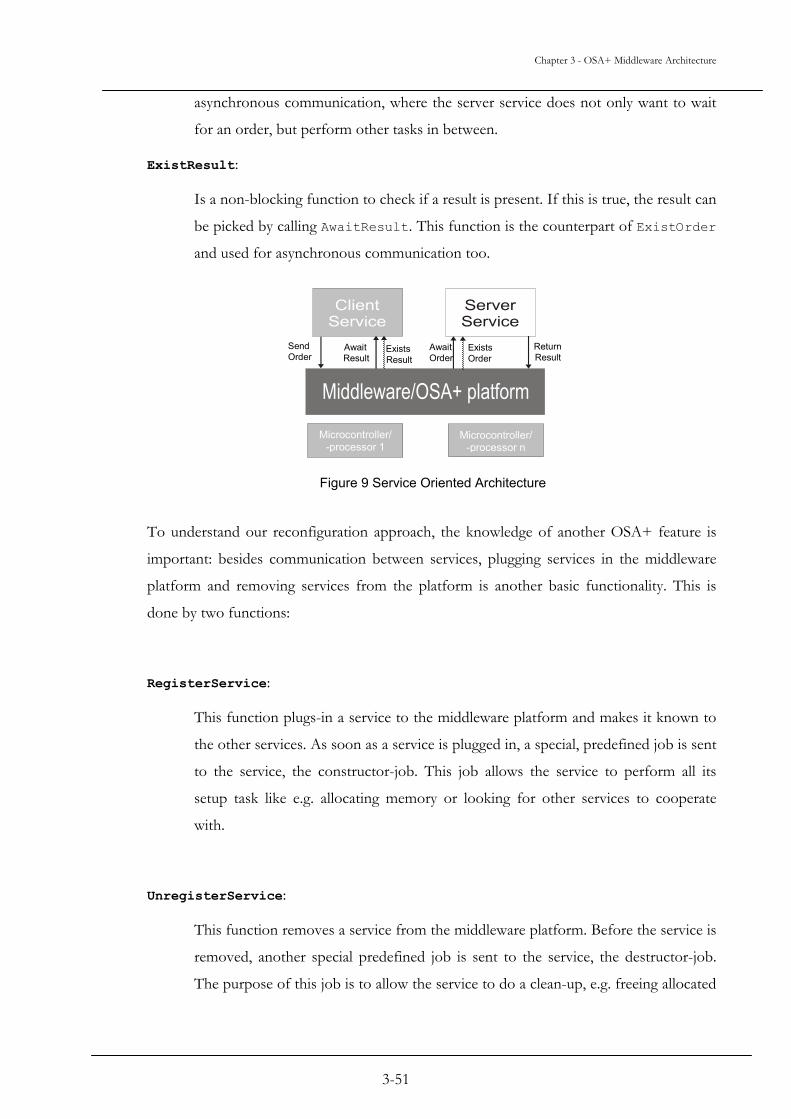
Chapter 3 - OSA+ Middleware Architecture
asynchronous communication, where the server service does not only want to wait
for an order, but perform other tasks in between.
ExistResult:
Is a non-blocking function to check if a result is present. If this is true, the result can
be picked by calling AwaitResult. This function is the counterpart of ExistOrder
and used for asynchronous communication too.
Send Order Await
ResultExistsOrder
Return Result Exists
ResultAwait Order
Microcontroller/-processor 1
Microcontroller/-processor n
Figure 9 Service Oriented Architecture
To understand our reconfiguration approach, the knowledge of another OSA+ feature is
important: besides communication between services, plugging services in the middleware
platform and removing services from the platform is another basic functionality. This is
done by two functions:
RegisterService:
This function plugs-in a service to the middleware platform and makes it known to
the other services. As soon as a service is plugged in, a special, predefined job is sent
to the service, the constructor-job. This job allows the service to perform all its
setup task like e.g. allocating memory or looking for other services to cooperate
with.
UnregisterService:
This function removes a service from the middleware platform. Before the service is
removed, another special predefined job is sent to the service, the destructor-job.
The purpose of this job is to allow the service to do a clean-up, e.g. freeing allocated
3-51

Chapter 3 - OSA+ Middleware Architecture
memory, before it is removed. Furthermore, a service is able to refuse to be
removed by returning a negative result for the destructor-job.
This is important for our approach, because plugging-in and removing services at run-time
is a basic functionality for dynamic reconfiguration. Additionally, we will introduce another
special predefined job, the reconfigurator-job. This job is sent to a service to allow to
prepare for reconfiguration. Job-based reconfiguration is one of the key concepts of our
approach described in chapter 4.
3.2 Microkernel architecture
In order to provide scalability and to adapt to small systems with low resources and to full
size systems as well, OSA+ uses a microkernel architecture. This makes the middleware
suitable to be used in embedded environment. OSA+ consists of small, uniform building
blocks.
Figure 10 shows the overall structure. The core of the OSA+ platform offers only a basic
functionality, which is registering/unregistering of local services and local job exchange.
This helps to keep the core small. Furthermore, no parts depending on the environment
(operating system, communication system, ...) are contained. Because the core is able to
register and interact with local services, exactly these services can be used to adapt to the
environment and to extend the functionality. No special libraries or objects are necessary to
adapt or to scale the middleware. The services as a building block are a uniform concept to
setup and extend the microkernel and to form the application. We have defined a set of
basic services for that purpose: the process service adapts to the operating system and is
responsible for service scheduling. The memory service adapts also to the operating
system and is responsible for dynamic memory allocation. The event service deals with
real-time events and time-related job delivery. The communication service adapts to the
underlying communication system and is responsible for remote job delivery. The address
resolution service deals with finding remote services. There are no differences between a
basic service and a user service. The core platform treats them in the same way. This keeps
the core small and simple. It allows scaling and adapting the middleware in an easy way. On
very small systems, the core can operate standalone with a restricted functionality. As
necessary, basic services can be added. Furthermore, it is possible to provide a basic service
with different qualities and resulting memory sizes.
3-52

Chapter 3 - OSA+ Middleware Architecture
In Addition to the basic services and user application services, extension services can be
written to add new functionalities to the platform, e.g. error logging or job encryption.
User Services User Services
OSA+ Core (Microkernel)
Basic Services Extension Services
Adaptation to the environment Functional extensions
Figure 10 OSA+ Microkernel Architecture
3.3 Real-time Issues
3.3.1 Core Issues
Since the core is kept on a simple, environment independent level and does not deal with
issues like e.g. thread scheduling (this is the task of the process service), the core real-time
issues are simple:
- The core functions are divided into two groups: initialization functions (e.g. plug in
a service) and operational functions (e.g. SendOrder). The initialization functions
preallocate all necessary resources (e.g. memory) for the operational functions. So
while the execution time of initialization functions may be unpredictable, the
operational functions are completely static and offer a constant and tightly bounded
time behavior.
- The job queues maintained by the job delivery component of the core are
prioritized. This means, high priority jobs will overtake low priority jobs in these
queues. This important for the real-time features of our job-based reconfiguration
approach too. To maintain the priority of a job on all its way through the system,
this priority is as well delivered to the process service (service scheduling) and the
communication service (remote delivery).
3-53

Chapter 3 - OSA+ Middleware Architecture
3.3.2 Quality of Service Control and Assessment
The overall real-time behavior of a middleware depends on the underlying components like
the operating or the communication system. This means, the core real-time issues described
in the previous section are only one facet. The real-time properties of the underlying
components are introduced to the core by the basic services (e.g. OS scheduling policies are
introduced by the process service). Different configurations are possible: for example, with
a real-time OS (process service) but a non real-time communication system (communication
service), local jobs but not remote jobs can be handled in real-time.
To deal with such different configurations, OSA+ prescribes that every service must
provide quality of service (QoS) information for the platform and all other services, which
want to use it. This is done by a special QoS report function every service must be able to
execute. For example, the process service has to report the available scheduling policies
(non-realtime, FPP, EDF, etc.) by this function. Using the QoS report functions the core
and the user services can evaluate the overall real-time properties.
The QoS report function can be used as well to provide different qualities and resulting
memory sizes for the same basic service. While e.g. a simple and small version of the
process service offers and reports only one simple scheduling policy (may be FPP), a more
complex version can realize several different schemes.
3.3.3 Real-time memory service
The OSA+ memory service is a good example for the use of the QoS report function. This
service can report two important properties:
- memory locking
- real-time memory allocation
If both are not present, no real-time operation can be performed at all because even so all
needed memory is preallocated by the core initialization functions, it may be swapped out
during operation by the OS. Fortunately, at least memory locking is offered by most OS
platforms, or swapping is not implemented at all for microcontroller OS platforms.
3-54

Chapter 3 - OSA+ Middleware Architecture
If real-time memory allocation (this means the allocation time for a piece of memory is
predictable) is available, the core can introduce more dynamics. Memory does not have to
be preallocated by the initialization functions, but can be dynamically allocated by the
operational functions. For example, if no real-time memory allocation is present the
maximum job size and number of simultaneous jobs for a service has to be defined
statically at initialization time. With real-time memory allocation this can be handled at run-
time. Some systems like PERC or Metronome are providing real-time memory allocation.
3.3.4 Event service
W
b
c
in
d
A
r
in
F
v
e
s
t
sourceplatform
destinationplatform
job cr
eated
earli
est s
tart o
f deli
very
lates
t end
of de
liver
y
lates
t end
of de
liver
y
orde
r deli
vered
earli
est s
tart o
f exe
cutio
n
lates
t end
of ex
ecuti
on
deliv
ering
orde
r
deliv
ering
resu
ltea
rlies
t star
t of d
elive
ry
result
rece
ived
result
rece
ived
lates
t end
of cy
cle / j
ob
lates
t end
of cy
cle / j
ob
cycle 1 cycle nperiod
. . .
Figure 11 Real-Time Scheduling
hile the other basic services contribute in a more passive way to the overall real-time
ehavior by offering real-time features (like RT scheduling policies, prioritized
ommunication, etc.), the event service plays an active role. This service is responsible for
itiating all time triggered actions. Figure 11 shows the possible states and times of a job
uring job scheduling.
ll the release times (earliest start of...) are handled by the event service. It is the
esponsibility of this service to trigger the delivery of a job at the requested time. This
cludes single job delivery as well as an automatic periodic delivery with a given cycle time.
urthermore, the event service monitors all the deadlines (latest end of ...). If a deadline is
iolated, the event service reports an error. Note, that all times are optional. So a simple
vent service may not support all of the times or actions (e.g. no periodic actions) and thus
aving memory. The QoS report function of the event service is responsible for providing
his information.
3-55

Chapter 3 - OSA+ Middleware Architecture
3-56
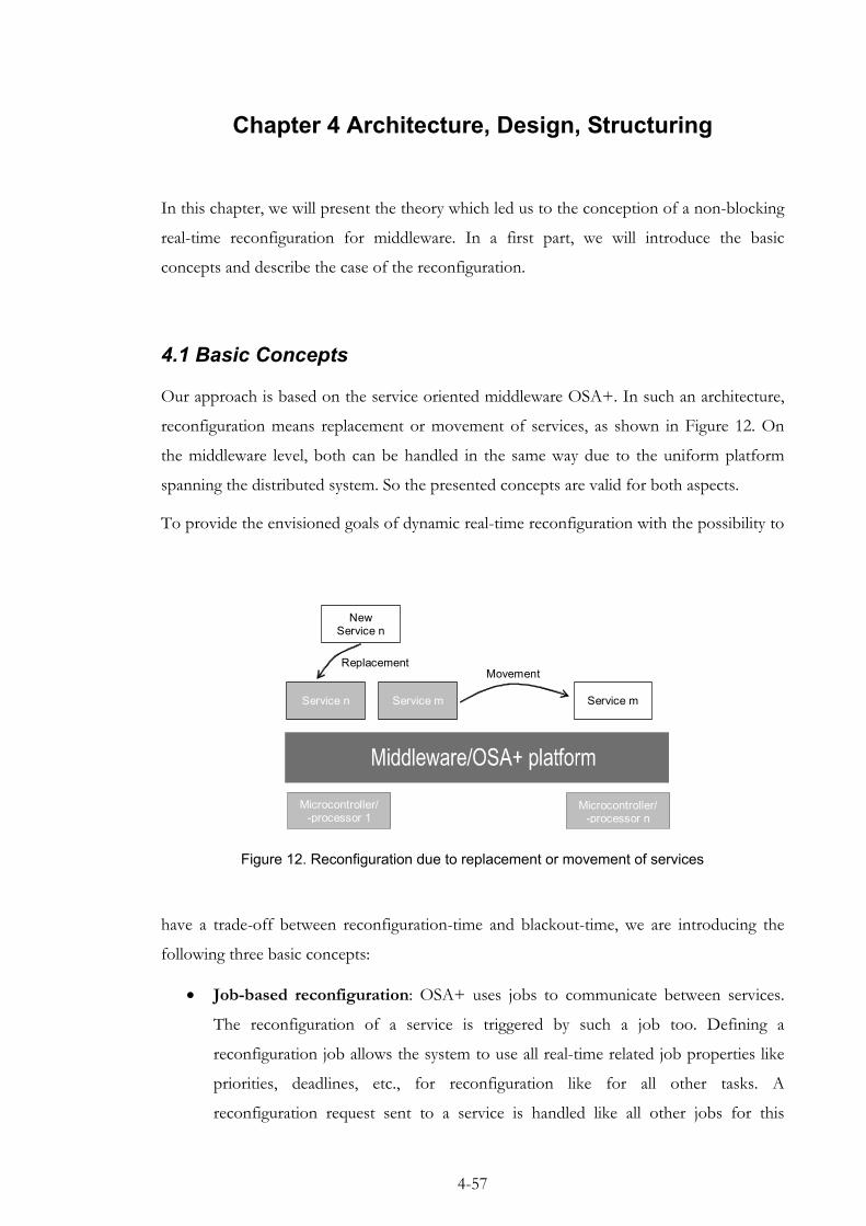
Chapter 4 Architecture, Design, Structuring
In this chapter, we will present the theory which led us to the conception of a non-blocking
real-time reconfiguration for middleware. In a first part, we will introduce the basic
concepts and describe the case of the reconfiguration.
4.1 Basic Concepts
Our approach is based on the service oriented middleware OSA+. In such an architecture,
reconfiguration means replacement or movement of services, as shown in Figure 12. On
the middleware level, both can be handled in the same way due to the uniform platform
spanning the distributed system. So the presented concepts are valid for both aspects.
To provide the envisioned goals of dynamic real-time reconfiguration with the possibility to
have a trade-off between reconfiguration-time and blackout-time, we are introducing the
following three basic concepts:
Microcontroller/-processor 1
Microcontroller/-processor n
Service n Service m Service m
New Service n
Movement Replacement
Figure 12. Reconfiguration due to replacement or movement of services
• Job-based reconfiguration: OSA+ uses jobs to communicate between services.
The reconfiguration of a service is triggered by such a job too. Defining a
reconfiguration job allows the system to use all real-time related job properties like
priorities, deadlines, etc., for reconfiguration like for all other tasks. A
reconfiguration request sent to a service is handled like all other jobs for this
4-57

Chapter 4 - Architecture, Design, Structuring
service, see Figure 13. If there a jobs with higher priorities, they are executed before,
jobs with lower priorities are executed after the reconfiguration. Therefore, dynamic
reconfiguration respects real-time priorities and deadlines. A problem will occur
concerning jobs with lower priority than the one of the reconfiguration job: without
any special checks, these jobs will be processed after the reconfiguration was done.
If jobs have to be processed before the reconfiguration, it might be necessary to
modify their priorities, in such a case, the user should be aware of possible side
effects.
Service
Job 1 (Data Processing) Priority or Deadline
1
Job 2 (Data Processing) Priority or Deadline
2
Job 3 (Reconfiguration)
Priority or Deadline 3
Job 4 (Data Processing) Priority or Deadline
4
Figure 13. Job based reconfiguration
• Monitored on-the-fly state transfer: As long as no state transfer is necessary
(stateless services), switching of services for reconfiguration is easy. The new or
moved version of a service can be plugged into the platform with the old version
still working. Then the switch can be done instantly by switching the connections.
The blackout-time is minimal. When state needs to be transferred, the blackout-time
increases, because the old version of the service must be stopped, then the state can
be transferred and finally the new version can be activated.
In our approach, we offer the possibility to transfer the state without stopping the
service to be switched. Therefore, we have to deal with state changes during
transfer. By constantly monitoring the remaining amount of state to be transferred
(which might increase and decrease), it is possible to define a desired maximum
blackout-time (Figure 14). As soon as the remaining amount of state can be
transferred within the requested blackout-time, the old service can be stopped, the
remaining state transferred and the new or moved service started.
Of course, as lower the requested blackout-time, as higher can become the
reconfiguration-time. If there exists an upper bound for this reconfiguration-time is
a main research question, which will be answered in the evaluation section.
4-58
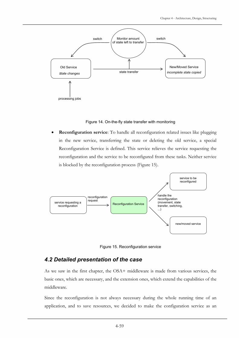
Chapter 4 - Architecture, Design, Structuring
Old Service New/Moved Service
Monitor amount of state left to transfer
state transfer
processing jobs
state changes
switch switch
incomplete state copied
Figure 14. On-the-fly state transfer with monitoring
• Reconfiguration service: To handle all reconfiguration related issues like plugging
in the new service, transferring the state or deleting the old service, a special
Reconfiguration Service is defined. This service relieves the service requesting the
reconfiguration and the service to be reconfigured from these tasks. Neither service
is blocked by the reconfiguration process (Figure 15).
service requesting a reconfiguration Reconfiguration Service
service to be reconfigured
new/moved service
reconfiguration request
handle the reconfiguration (movement, state transfer, switching, ...)
Figure 15. Reconfiguration service
4.2 Detailed presentation of the case
As we saw in the first chapter, the OSA+ middleware is made from various services, the
basic ones, which are necessary, and the extension ones, which extend the capabilities of the
middleware.
Since the reconfiguration is not always necessary during the whole running time of an
application, and to save resources, we decided to make the configuration service as an
4-59

Chapter 4 - Architecture, Design, Structuring
extension service. However it is still possible to have it running all the time with the main
services, if the resources are available.
We define a reconfiguration as a replacement of a service by another one, or the movement
of a service. Thus a service, when “reconfigured”, is able to continue processing the orders
sent by services, which are not aware of its reconfiguration. This reconfiguration is triggered
by another service. Our objective is to have all services continuing their jobs while the
reconfiguration is started and processed, even the service which has to be reconfigured.
OldVersion Service
DynamicCon Service
Triggering Service
Lambda Service
Result
Order
NewVersion Service
Figure 16. Reconfiguration Principle
A typical reconfiguration of a service is done as shown in Figure 16. There are five services,
which are involved in the reconfiguration, but it may happen that only four of them are
concerned: The Triggering Service and the Lambda Service can be the same service,
responsible for requesting a reconfiguration of another service. Here is how the
reconfiguration occurs:
The Lambda Service normally sends orders to the OldVersion Service. This one
processes the requests and, when done, sends back results.
Another service, the Triggering Service, makes a request to the
Reconfiguration Service named the DynamicCon Service in the figure, for the
reconfiguration of the OldVersion Service and its replacement by the NewVersion
Service.
4-60
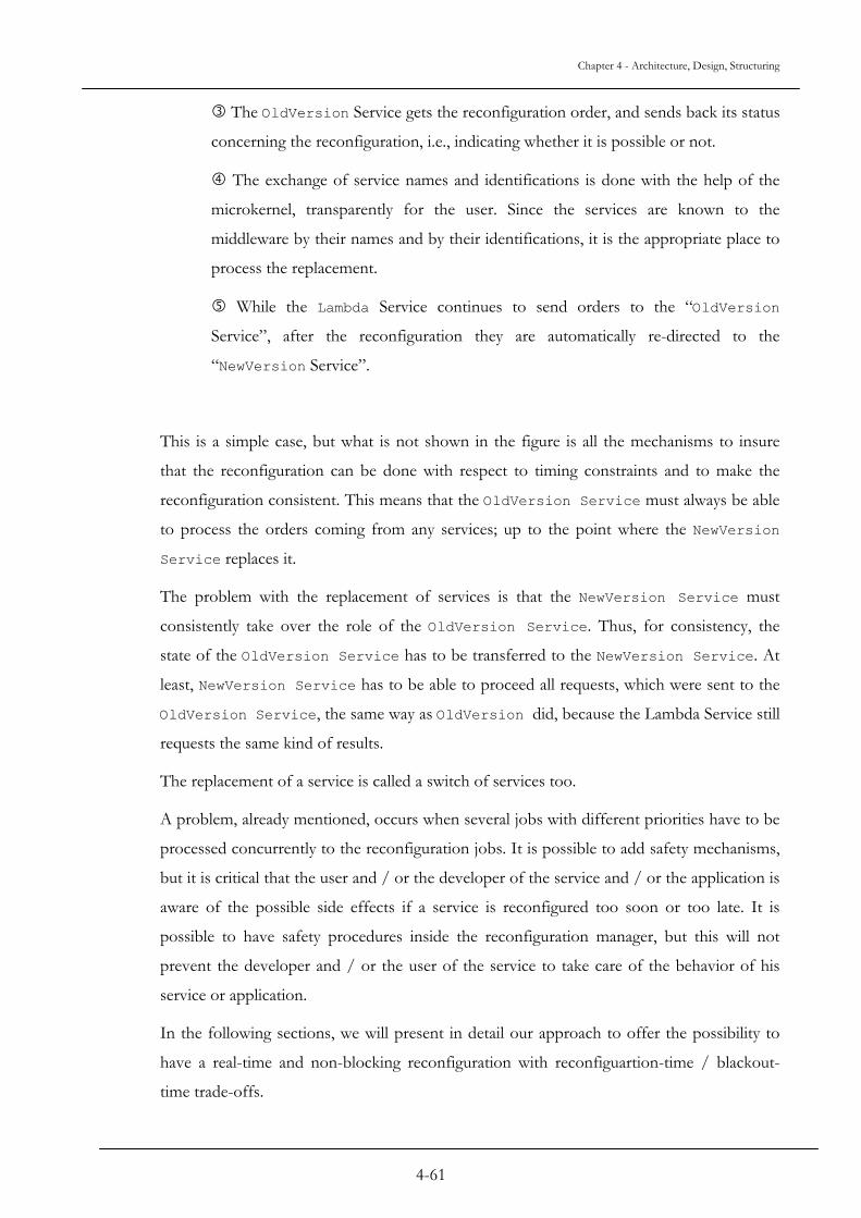
Chapter 4 - Architecture, Design, Structuring
The OldVersion Service gets the reconfiguration order, and sends back its status
concerning the reconfiguration, i.e., indicating whether it is possible or not.
The exchange of service names and identifications is done with the help of the
microkernel, transparently for the user. Since the services are known to the
middleware by their names and by their identifications, it is the appropriate place to
process the replacement.
While the Lambda Service continues to send orders to the “OldVersion
Service”, after the reconfiguration they are automatically re-directed to the
“NewVersion Service”.
This is a simple case, but what is not shown in the figure is all the mechanisms to insure
that the reconfiguration can be done with respect to timing constraints and to make the
reconfiguration consistent. This means that the OldVersion Service must always be able
to process the orders coming from any services; up to the point where the NewVersion
Service replaces it.
The problem with the replacement of services is that the NewVersion Service must
consistently take over the role of the OldVersion Service. Thus, for consistency, the
state of the OldVersion Service has to be transferred to the NewVersion Service. At
least, NewVersion Service has to be able to proceed all requests, which were sent to the
OldVersion Service, the same way as OldVersion did, because the Lambda Service still
requests the same kind of results.
The replacement of a service is called a switch of services too.
A problem, already mentioned, occurs when several jobs with different priorities have to be
processed concurrently to the reconfiguration jobs. It is possible to add safety mechanisms,
but it is critical that the user and / or the developer of the service and / or the application is
aware of the possible side effects if a service is reconfigured too soon or too late. It is
possible to have safety procedures inside the reconfiguration manager, but this will not
prevent the developer and / or the user of the service to take care of the behavior of his
service or application.
In the following sections, we will present in detail our approach to offer the possibility to
have a real-time and non-blocking reconfiguration with reconfiguartion-time / blackout-
time trade-offs.
4-61
Chapter 4 - Architecture, Design, Structuring
4.3 Design
We first have to evaluate when this switch of the two services has to be done. Depending
on this switching time, more or less work has to be done to not jeopardize the consistency
of the service itself, or the one of the system.
In fact, the following switching times are possible:
- When a service is looking for a new job (a),
- When a service is looking for a new job or sending a result (b),
- Or anytime (c).
The second question is about the state of the service. We can distinguish two types of state
information:
- The outer job state of a service. It is all variables that are necessary to correctly
process an arriving job,
- The inner job state of a service. It is composed by all variables that are only valid
during the processing of a job.
Depending on the switching time, the state information to be transferred differs:
- In case of switching only when looking for a job, case (a), only the outer job state
must be saved,
- In case of switching anytime or even while sending a result, cases (b, c), the inner
job state must be saved as well.
Often, a service will be replaced for two main reasons:
• For a functional service update:
In this case, switching time (b) or (c) is critical, because the new version of the service
might perform other algorithms, and thus can make the inner job state incompatible. It
might not be possible to resume a half completed job
• Service movement (for example due to load balancing) from one platform to another:
4-62

Chapter 4 - Architecture, Design, Structuring
In this case all three variants are possible and might be useful.
We have decided to focus on switching time (a), since our approach addresses both kinds of
reconfiguration and the amount of state information is lower (only the outer state)
4.3.1 Basic algorithm
Here is the outline of our basic reconfiguration algorithm. In the following, we call the
service to be reconfigured the source service and the new (or moved) service the destination
service.
1. A reconfiguration is requested by a job and processed according to the job
parameters (priority, deadline, ...)
2. As soon as the reconfiguration job gets processed, the Reconfiguration Service
(DynamicCon) starts to transport the outer state information of the source service to the
destination service while the source service is still running.
3. The Reconfiguration Service monitors the outer state for more parts to be
transported (due to incomplete transport or state changes of already transported parts for
example). tt is the time necessary to transport the remaining state information and tb is the
requested blackout-time.,
if tt < tb
then
the source service is stopped and the remaining state information is transported
and the reconfiguration is completed. The new job is executed by the destination
service.
else
the new job is executed by the source service and this algorithm continues again
with step 2.
In this case, a problem occurs: the reconfiguration time might be unbounded! Thus, the
switching of services may never fully happen, because there would still be state information
to transfer between both versions of the service. If a service cannot be replaced by its new
4-63

Chapter 4 - Architecture, Design, Structuring
version, this means there is no reconfiguration. To handle this issue, we will refine the base
algorithm in the following section and investigate if and how the reconfiguration-time can
be bounded.
4.3.2 Main principle
To replace and move a service from one platform to another, or just to update an old
version of a service, different steps are needed.
In a general matter, the service to be reconfigured, namely the OldVersion Service is
already launched and active, i.e. processing jobs when it is about to replace it with an
improved service (or move to another platform), namely the NewVersion Service.
Load a service on a platform
First to be able to use a service, it must be plugged into the OSA+ platform. If a service
shall be moved, it must be transported to the destination platform as well. Once the new
service is on the platform, it is activated after the Constructor-Job order is sent; thus the
service is ready to receive and process orders.
These few steps can be schematized as following:
Load a service: [Transport the service] (optional)
Plug-In the service
Send the Constructor-Job
Note: The Constructor-Job allows the service to setup and initialize its variables and
state information, making it ready to be used.
Remove a service on a platform
Once the new version of the service is loaded and active, the old version of the service will
receive a Destructor-Job order. This order sets this service in a state readying its disabling.
Then, once the service is disabled, it can be deleted from the platform if it is necessary. This
is often the case on a resource-limited system.
Remove a service: Send the Destructor-Job
4-64
Chapter 4 - Architecture, Design, Structuring
Unplug the service
[Delete the service] (optional)
Note: The Destructor-Job allows the service to clean up. Furthermore, the
Destructor-Job can have a priority so the time of destruction is given by the position of
the Destructor-Job among other jobs in the service queue.
Replacement of a service
When the new version of a service has to replace its old version, the new service will get a
temporary name, called a shadow name, so both versions can coexist at the same time with
the old version still active. Then the new version service is activated with a Constructor-
Job. The old version of the service is set in a reconfigurable state by sending the
Reconfigurator-Job; and so the switch between the two versions occurs. To complete
the reconfiguration, the old version of the service receives a Destructor-Job to prevent it
from being used again. The old service can be deleted if necessary.
Replace a service: [Transport the new service](optional)
Plug-In the new service using a shadow name
Send the Constructor-Job to the new service
Send the Reconfigurator-Job to the old service
Send the Destructor-Job to the old service
Unplug the old service
[Delete the old service](optional)
In case where the state information needs to be transferred from the old service to the new
one, the Constructor-Job sent to the new service indicates this by a special parameter.
Then, the new service sends a “StateTransfer” message to the Reconfiguration Service to
initiate the state transfer.
When the old service receives the Reconfigurator-Job, it sends a “Switch” message to
the middleware. This function stops the old service thus allowing the Reconfiguration
Service to finish the state transfer and swaps the services so the old service is now the
4-65

Chapter 4 - Architecture, Design, Structuring
shadow service while the new service is the working one (e.g. by swapping entries in the
service table of the middleware). Both names and identifications are exchanged.
Note: the reconfiguration time is given by the position of the Reconfigurator-Job
among the other jobs in the service queue.
Possible cooperations of “TransferState” and “Switch”
In the previous paragraphs, the principal algorithm is given to explain how the
reconfiguration is handled in our approach. Now, we discuss in detail the state transfer and
switching of the services. Three different concepts can be distinguished:
- The full-blocking approach
On calling “TransferState”, the new service is blocked until the old service calls
“Switch” to initiate the exchange of both services. After the switch is executed, the
state is transferred. This guarantees consistent and identical state info on both services,
but causes the longest blackout time (cf. Figure 17). This approach is efficient especially
for a service, which does not have a big amount of variables, or which is not often used,
so that its state is stable for a long time.
New Service
Old Service
Receives “Constructor”
Receives “Reconfiguration”
Calls “TransferState”
blocked
unblockswap services
Calls “Switch”
transfer state
Reconfiguration time
Middleware
Blackout time
Figure 17. The full blocking approach
- The partial-blocking approach
On calling “TransferState”, the new version of a service starts to transfer the state
information. The Reconfiguration Service inherits the control flow from the new service
4-66

Chapter 4 - Architecture, Design, Structuring
so the old version of the service is not blocked. The Reconfiguration Service is fully
reentrant so it can have multiple control flows in order to perform multiple
simultaneous reconfigurations. As the old version of the service calls “Switch”, the
services are swapped and the remaining state information is transferred (cf. Figure 18).
This guarantees consistent and identical state info as well and reduces the blackout time,
because state information is transported in parallel to the old working service. Still, there
is a blocking time while the swap is done and the remaining state info is transferred.
- The non-blocking approach
Like for the partial-blocking approach, the new version of the service starts to transfer
the state info on calling “TransferState”.
As the old version of the service calls “Switch”, the remaining amount of state
information to transfer is monitored. If the time necessary to transfer this
information is less than the requested blackout-time, the swap is done and the
remaining state information is transferred. Otherwise, the swap is delayed. This
means, “Switch” returns without swapping the services and “TransferState”
continues to transfer the state information. From now on, every time the old
version of the service looks for a new job, an automatic call to “Switch” is executed
by the middleware to check if the swap can be processed. If the remaining time to
transfer the state information is less than the requested blackout-time, the swap is
made (cf. Figure 19). This approach
4-67
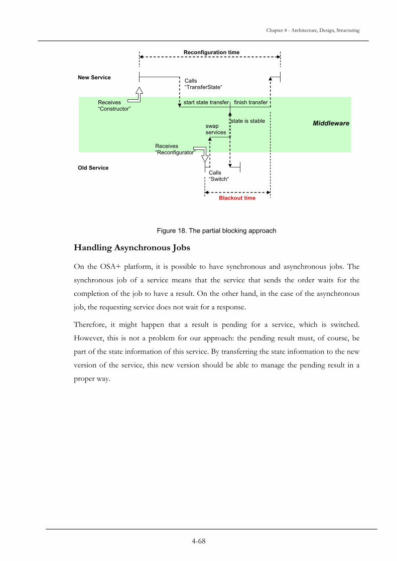
Chapter 4 - Architecture, Design, Structuring
New Service
Old Service
Receives “Constructor”
Receives “Reconfigurator”
Calls “TransferState“
state is stableswap services
Calls “Switch“
start state transfer
Reconfiguration time
Middleware
finish transfer
Blackout time
Figure 18. The partial blocking approach
Handling Asynchronous Jobs
On the OSA+ platform, it is possible to have synchronous and asynchronous jobs. The
synchronous job of a service means that the service that sends the order waits for the
completion of the job to have a result. On the other hand, in the case of the asynchronous
job, the requesting service does not wait for a response.
Therefore, it might happen that a result is pending for a service, which is switched.
However, this is not a problem for our approach: the pending result must, of course, be
part of the state information of this service. By transferring the state information to the new
version of the service, this new version should be able to manage the pending result in a
proper way.
4-68
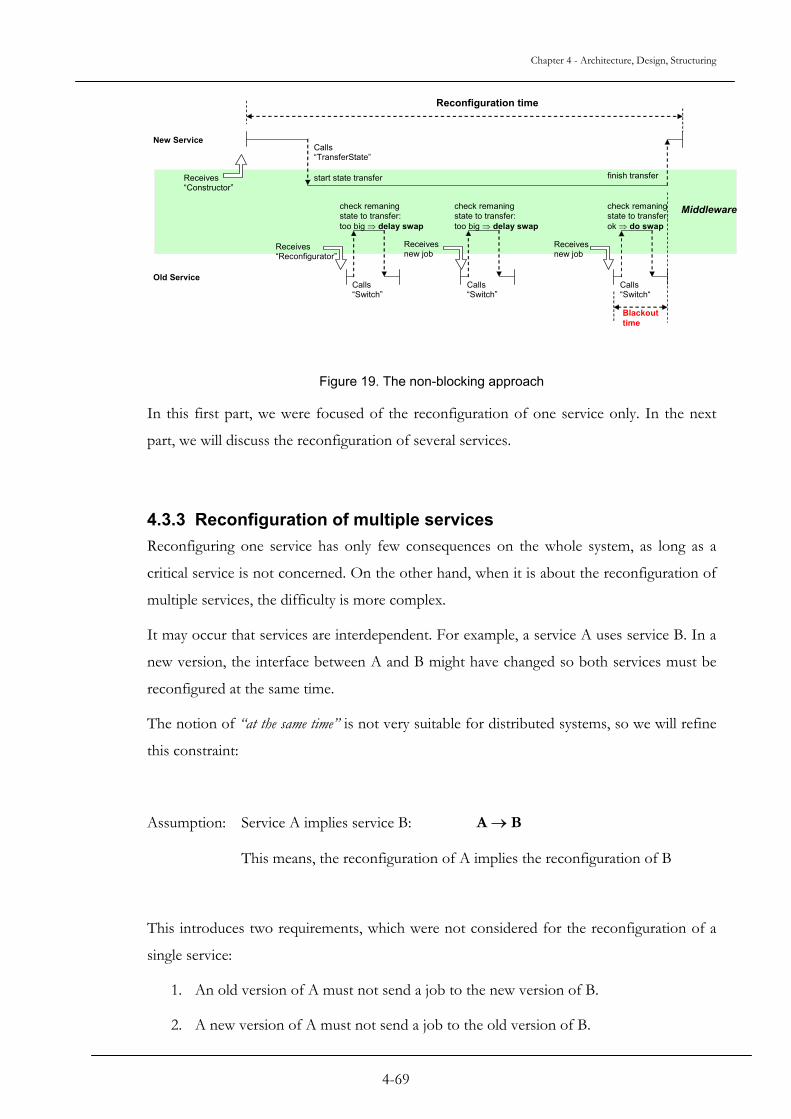
Chapter 4 - Architecture, Design, Structuring
New Service
Old Service
Receives “Constructor”
Receives “Reconfigurator”
Calls “TransferState”
check remaning state to transfer: too big ⇒ delay swap
Calls “Switch”
start state transfer
Reconfiguration time
Middleware
finish transfer
Receives new job
Calls “Switch”
Receives new job
Calls “Switch“
check remaning state to transfer: too big ⇒ delay swap
check remaning state to transfer: ok ⇒ do swap
Blackouttime
Figure 19. The non-blocking approach
In this first part, we were focused of the reconfiguration of one service only. In the next
part, we will discuss the reconfiguration of several services.
4.3.3 Reconfiguration of multiple services Reconfiguring one service has only few consequences on the whole system, as long as a
critical service is not concerned. On the other hand, when it is about the reconfiguration of
multiple services, the difficulty is more complex.
It may occur that services are interdependent. For example, a service A uses service B. In a
new version, the interface between A and B might have changed so both services must be
reconfigured at the same time.
The notion of “at the same time” is not very suitable for distributed systems, so we will refine
this constraint:
Assumption: Service A implies service B: A → B
This means, the reconfiguration of A implies the reconfiguration of B
This introduces two requirements, which were not considered for the reconfiguration of a
single service:
1. An old version of A must not send a job to the new version of B.
2. A new version of A must not send a job to the old version of B.
4-69

Chapter 4 - Architecture, Design, Structuring
If we look at the previously discussed reconfiguration process of a single service, for all the
approaches discussed, there exists a blackout interval beginning with swapping services and
ending with completing the state transfer (cf. Figure 20)
swap service remaining state transfer
blackout time
old service stopped
new service started
Figure 20. Overview of the Reconfiguration Process
We can fulfill the requirements 1 and 2 with the following simple conditions:
A → B
1. old version of B must be stopped after old version of A is stopped. 2. old version of B must be stopped before new version of A is started.
The condition 1 fulfills requirement 1: if the old version of B is stopped after the old
version of A is stopped, never the old version of A can send a job to new B (because the
old version of A is stopped before the old version of B)
The condition 2 fulfills requirement 2: if the old version of B is stopped before the new
version of A is started, then the new version of A can never send a job to the old version of
B.
The Figure 21 presents the overview of the reconfiguration of two services, which are
interdependent. It appears that the overall blackout time is the addition of the blackout-
times for both services.
It is obvious that the overall blackout-time can be minimized by stopping service B as soon
as possible after stopping service A
4-70
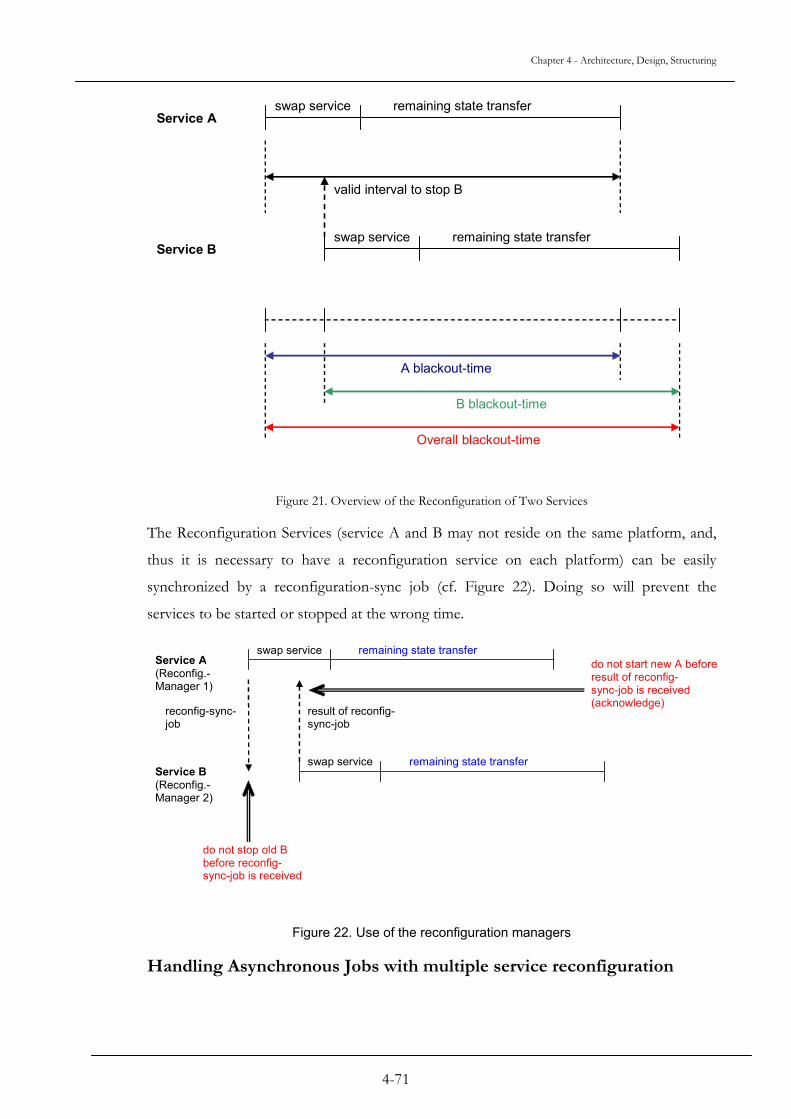
Chapter 4 - Architecture, Design, Structuring
swap service remaining state transfer Service A
Service B swap service remaining state transfer
valid interval to stop B
A blackout-time
B blackout-time
Overall blackout-time
Figure 21. Overview of the Reconfiguration of Two Services
The Reconfiguration Services (service A and B may not reside on the same platform, and,
thus it is necessary to have a reconfiguration service on each platform) can be easily
synchronized by a reconfiguration-sync job (cf. Figure 22). Doing so will prevent the
services to be started or stopped at the wrong time.
swap service remaining state transfer Service A (Reconfig.- Manager 1)
Service B (Reconfig.- Manager 2)
swap service remaining state transfer
reconfig-sync- job
result of reconfig- sync-job
do not stop old B before reconfig- sync-job is received
do not start new A before result of reconfig- sync-job is received (acknowledge)
Figure 22. Use of the reconfiguration managers
Handling Asynchronous Jobs with multiple service reconfiguration
4-71

Chapter 4 - Architecture, Design, Structuring
Asynchronous jobs introduce no additional problems as long as the service A itself offers a
synchronous interface. This means (cf. Figure 23):
job
Service A
Service B
sub-job sub-job sub-result sub-result
result job
synchronous interface
asynchronous jobs to sub-services
Figure 23. Management of asynchronous jobs
- The service, in our example: A, does not look for a new job unless the old job is completed.
- But all sub-jobs directed to other services (e.g. Service B) in order to complete the
given job can be processed asynchronously.
This guarantees that there is no pending result for Service A when this Service A is looking
for a new job (and therefore might be reconfigured).
If the condition of the synchronous interface is not met, pending results might set the
services, or even worst, the whole system in an inconsistent state. From our example, let’s
assume Service A is operating fully asynchronous on its interface, thus there will be pending
results for Service A, respectively pending jobs for Service B once that Service A is stopped
(e.g. Figure 24).
In this case even if the old version of service B is stopped after the old version of service A
is stopped and before the new version of service A is started, the new service A might get a
result from the old version of service B (the pending result) or the new version of service B
might get a job from the old version of service A (the pending job).
To avoid this situation, there are two possibilities:
- The service-driven approach: as soon as a service receives a reconfigurator-job, which means the system has to replace this service, the service must clean up and be assured that there is no more pending job or results. This is the same approach as for the destructor-job, which shall enable the service to clean-up before being removed.
4-72

Chapter 4 - Architecture, Design, Structuring
- The system-driven approach: the old version of service A is not stopped by the system (the middleware) as long as there is pending jobs or results, which are sent by or to the old version of service A.
job 1
Service A
Service B
sub-job 1 sub-job 2 queued (service B e.g. busy)
sub-result 1 queued
asynchronous interface
job 2 (before result 1 is returned)
stopped for reconfiguration pending result
pending job
Figure 24. Inconsistencies due to asynchronous interface
To realize the system-driven approach, there are again two possibilities:
- Stopping the old version of service A is delayed until there are no more pending jobs or results. The old version of service A, meanwhile, is kept fully operational. This minimizes the blackout-time, but increases the reconfiguration time (maybe unbounded).
- The old version of service A is stopped in a way that no more new jobs arrives (the
connections to A are cut for the incoming jobs), but the old version of service A is still
able to process results and to give jobs to sub-services (incoming results, outgoing jobs).
The transfer of the remaining state information is delayed until all pending results and
jobs are processed and therefore have contributed to modify the state. Then, the old
version of service A is fully stopped and the remaining state information is transferred
to the new version of service A (cf. Figure 25).
Pending results or jobs are checked every time the service looks for a job or a result. This
approach reduces the reconfiguration time, but increases the blackout time.
4-73

Chapter 4 - Architecture, Design, Structuring
cut new incoming jobs
old service A
completely swap
process pending results and jobs
transfer remaining state
Figure 25. Preventing inconsistencies
Furthermore, service A must meet the following requirement:
Incoming results must be checked and processed by the service independently of
incoming jobs. Otherwise, the service would block because all incoming jobs are
cut.
4.3.4 “Transfer-State” and “Switch” cooperation in multiple service reconfiguration
In the previous section we examined the cases of the reconfiguration of interdependent
services. In this part, we will focus more specially on the theory concerning the state
transfer information and the consequences on the reconfiguration of several services.
The three approaches “full-blocking”, “partial-blocking” and “non-blocking” can directly be
adapted:
4.3.4.1 Full-Blocking Approach
Old version of service A is directly stopped and swapped after calling “Switch”. Then, the
state transfer is processed. Service B is treated according to the previously defined
constraints (swap starts as soon as possible after the old version of service A is stopped and
before new version of service A is started)
4.3.4.2 Partial-Blocking Approach
The state transfers to the new version of services A and B are directly started after receiving
the constructor. As soon as the old version of service A calls “Switch”, service A is
swapped and the remaining state is transferred. B is swapped after A and before new
version of service A is started, but the state transfer to the new version of service A should
be finished. The remaining state information of B is transferred after B is swapped.
4-74
Chapter 4 - Architecture, Design, Structuring
4.3.4.3 Non-Blocking Approach
The state transfers to the new services A and B are directly started after receiving the
constructor. As soon as the old version of service A calls “Switch”, the remaining amount
of state information to transfer to the new version of service A is monitored. If the
necessary transfer-time is greater then the desired blackout-time, the switch is delayed and
then monitored again every time the old version of service A is looking for a new job.
Otherwise, the swap is done and the remaining state information is transferred.
Again, the service B is swapped after the service A and before the new version of service A
is started. The remaining state information of B is transferred after the swap.
For a multiple service reconfiguration, the non-blocking approach can be refined. In its
original form described above, this approach can have a drawback shown in the following
example:
Service A: only a small amount of state info to transfer
Service B: a large amount of state info to transfer (e.g. a database service for
service A)
In that case, A will reach the swap state very quickly and therefore B has not much time for
the state transfer. This causes a big blackout-time due to the amount of remaining state
information to transfer for B.
This issue can be solved by the following approach:
Non-Blocking-Combined Approach
In this approach, the remaining amount of state information to transfer is checked
for A and B. The swap of A is executed only if the time necessary to transfer the
remaining state of A and B is less the desired blackout-time.
4-75

Chapter 4 - Architecture, Design, Structuring
4.3.5 An alternate way to deal with reconfiguration of multiple services:
In case of A → B, A and B could be independently reconfigured by introducing a temporal
proxy service AB. This service transforms the requests of the new version of service A to
old version of service B or vice versa. In that case, a reconfiguration would look like as
follows:
1. Put proxy AB to system.
2. Replace the old version of service A by the new version of service A, direct
all jobs from the new version of service A to the old version of service B via
the proxy AB.
3. Replace the old version of service B by the new version of service B, then
reconnect services A and B directly.
4. Remove the proxy AB.
4.4 Reconfiguration- and Blackout-time bounds In this section, we examine the time bounds for the three different approaches.
4.4.1 Bounds for the full-blocking approach Time bounds for the full blocking approach are easy to determine. Since the old service is
fully operational until the services are swapped and the swapping time can be neglected2,
only the state transfer determines the blackout-time.
rSTBlackout =
where: S: amount of state to transfer
r: data transfer rate for the state transfer
2 The swapping time can be neglected due to the fact that swapping is done just by switching table entries in the microkernel, as described in the next chapter.
4-76
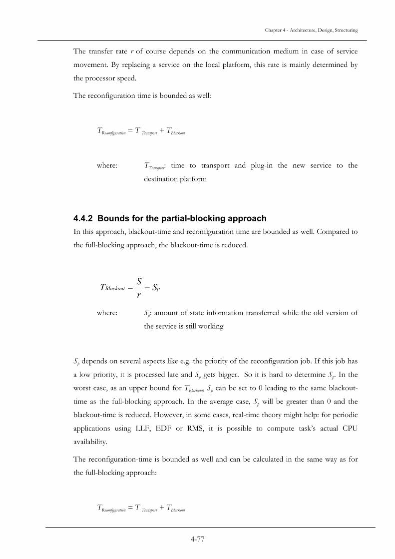
Chapter 4 - Architecture, Design, Structuring
The transfer rate r of course depends on the communication medium in case of service
movement. By replacing a service on the local platform, this rate is mainly determined by
the processor speed.
The reconfiguration time is bounded as well:
TReconfiguration = T Transport + TBlackout
where: TTransport: time to transport and plug-in the new service to the
destination platform
4.4.2 Bounds for the partial-blocking approach In this approach, blackout-time and reconfiguration time are bounded as well. Compared to
the full-blocking approach, the blackout-time is reduced.
pBlackout SrST −=
where: Sp: amount of state information transferred while the old version of
the service is still working
Sp depends on several aspects like e.g. the priority of the reconfiguration job. If this job has
a low priority, it is processed late and Sp gets bigger. So it is hard to determine Sp. In the
worst case, as an upper bound for TBlackout, Sp can be set to 0 leading to the same blackout-
time as the full-blocking approach. In the average case, Sp will be greater than 0 and the
blackout-time is reduced. However, in some cases, real-time theory might help: for periodic
applications using LLF, EDF or RMS, it is possible to compute task’s actual CPU
availability.
The reconfiguration-time is bounded as well and can be calculated in the same way as for
the full-blocking approach:
TReconfiguration = T Transport + TBlackout
4-77

Chapter 4 - Architecture, Design, Structuring
4.4.3 Bounds for the non-blocking approach This is the most interesting case since the reconfiguration time can be unbounded. We have
to investigate under which conditions the reconfiguration time is bounded and the value of
this bound.
Figure 26 presents the amount of time between two orders. T0 is the amount of time
necessary to process order i, while TP is the total amount of time between order i and order
i+1.
T0
TP
order i order i + 1
Figure 26. Processing time for orders
Let’s assume:
∆S : average amount of state changed during execution of an order
r : data rate for state transfer
A general condition for the state transfer to terminate is:
S∆
which means the chang
rTp
≤(1)
e rate of the state must be less or equal the transfer rate for the state.
4-78
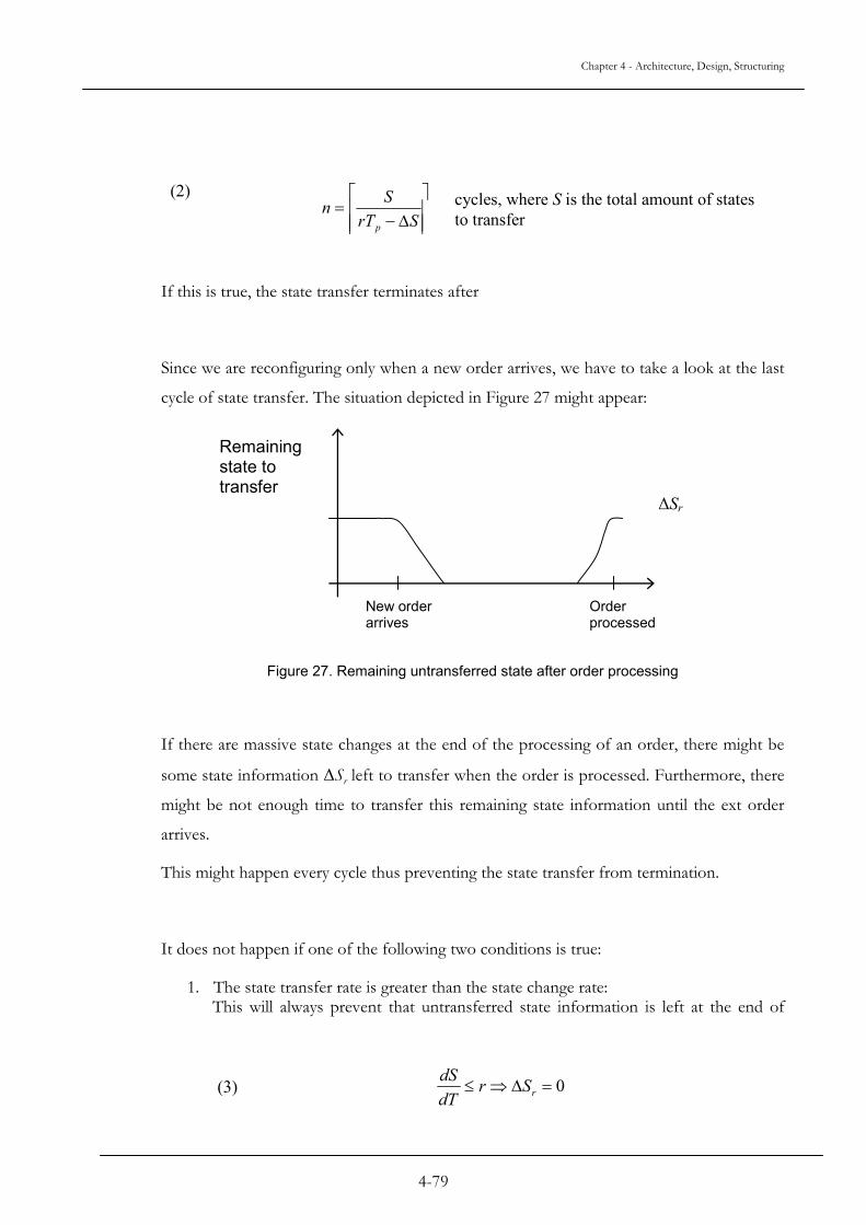
Chapter 4 - Architecture, Design, Structuring
⎤⎡ S(2)
⎥⎥⎥⎢
⎢⎢ ∆−
=SrT
np
cycles, where S is the total amount of states to transfer
If this is true, the state transfer terminates after
Since we are reconfiguring only when a new order arrives, we have to take a look at the last
cycle of state transfer. The situation depicted in Figure 27 might appear:
Remaining state to transfer
∆Sr
New order arrives
Order processed
Figure 27. Remaining untransferred state after order processing
If there are massive state changes at the end of the processing of an order, there might be
some state information ∆Sr left to transfer when the order is processed. Furthermore, there
might be not enough time to transfer this remaining state information until the ext order
arrives.
This might happen every cycle thus preventing the state transfer from termination.
It does not happen if one of the following two conditions is true:
1. The state transfer rate is greater than the state change rate: This will always prevent that untransferred state information is left at the end of
dS
0=∆⇒≤ rSrdT(3)
4-79

Chapter 4 - Architecture, Design, Structuring
order processing. Of course, this is a restrictive condition. Fortunately, there is a
second possibility:
2. The time between the end of the order and the start of the next order plus the allowed blackout time is big enough to transfer ∆Sr.
( )( ) rTTTS blackoutPr ⋅+−≤∆ 0
Of course, ∆Sr is always less or
So ∆S can be used as worst case
It follows:
For the state transfer to termina
here:
This means:
(4)
equal than ∆S: ∆Sr ≤ ∆S
value for ∆Sr
( )( ) rTTTS blackoutP •+−≤∆ 0
( ) blackoutP TTTrS
+−≤∆
0
0TTTT PPblackout +−≥
te at all, condition (1) must be true. So we can introduce (1)
PP
TrSr
TS
≤∆
⇒≤∆
0TTrST Pblackout +−
∆≥
0TTblackout ≥
4-80

Chapter 4 - Architecture, Design, Structuring
This means, that the reconfiguration, in the case of non-blocking approach, can complete
when condition (1) holds and the maximum allowed blackout-time is greater than the time
necessary to process the order.
If this is true, the upper bound for the blackout-time is of course less or equal the blackout-
time requested by the user or application:
TBlackout ≤ TBlackout requested
The reconfiguration time computes to:
TReconfiguration = TTransport + n ⋅ Tp, n according to equation (2)
In this chapter we presented our global approach for the reconfiguration of one or several
services on a middleware.
In the next chapter, the implementation of such algorithms will be discussed.
4-81


5-83
Chapter 5 Implementation Aspects
Our goal in implementing the Dynamic Reconfiguration in OSA+ is to evaluate and
demonstrate the feasibility of such a system on very weight embedded systems.
OSA+ is a microkernel-based middleware platform, which follows the requirements of real-
time and embedded systems. As a real-time hardware and operating system platform, the
Komodo microcontroller, a multithreaded real-time Java processor, can be used. The
discussion of our implementation of dynamic reconfiguration will not cover the
implementation and real-time mechanisms of the OSA+ middleware or the Komodo
microcontroller. For further explanation of both aspects, the reader should see [32] and
[31], which present details of these parts.
The topic of this chapter is to focus on the relevant aspects of the implementation
concerning dynamic reconfiguration. So, we will not discuss standard methods or classes
necessary for implementation. We will detail only the structures, which are of interest in
understanding and implementing the key features of our dynamic reconfiguration concepts.
5.1 Microkernel
This class is part of the standard OSA+, and thus to offer the dynamic reconfiguration
features, it was necessary to alter it.
Since the microkernel is the core of OSA+, all modifications done on that level have to be
done very carefully to not risk deterioration of the good performance of OSA+. It was
necessary to keep in mind during development that all changes to this class can have bad
influences on the results of the system. As the core of the system, only the needed parts
were done in the Microkernel class, i.e., the changes that are necessary for the system.
For this class, only one method was added. It is the method that is in charge of switching
two services: then the old version of a service will be replaced by the new version of a

Chapter 5 - Implementation Aspects
service. This switch is done only when the DynamicCon service sends a message to OSA+
to request the replacement of the old version of the service. The microkernel class is not in
charge of checking either these two services can be switched; this is the task of the
DynamicCon service.
In the current version of OSA+, the services are identified by two means:
- The service identifier, which is an integer value given by the system;
- The service name, which is a table of characters, usually given by the developer of
the service, but it is also possible to be given automatically.
ERROR
oldService = {oldServiceId, “oldServiceName”}
newService = {newServiceId, “newServiceName”}
tempName = “name”
serviceMgr : is an indexedCollection interface
checkings Not OK
OK
exchange the names with the help of tempName
exchange the identifiers
set the former newService as REGISTERED
[destruct the former oldService]
serviceMgr.exchange(oldService, newService)
Figure 28. Process of switching in the microkernel
On the microkernel level, to replace one service by another one, the names, after being
found back by the system, are exchanged, and then the service identifiers of both services
are exchanged too. By exchanging the identifiers, the new service gets the same identifiers
as the old service, thus all connections remain valid and now, point to the new service. At
last, the new service is flagged as being ready to receive orders and to send results.
5-84

Chapter 5 - Implementation Aspects
Figure 28 shows the process of switching. It was necessary to implement this switching
process in the microkernel for the following reasons:
• Regarding to the real-time properties, it is necessary to get the shortest possible
and bounded switching times. So searching service lists is not an option.
• By exchanging the name and the identifier directly in the data structures of the
microkernel, the switching process is extremely fast. Not only no search
operation is necessary, but by swapping the identifiers all related data structures
(e.g. job queues) are automatically swapped at the same time. The way the
swapping is done is described in the next section.
• Due to the already mentioned vital role of the microkernel, accessing the
internal data structures from outside is not advisable. System integrity may be
harmed if this would be allowed.
So the switch has been implemented as an additional method of the microkernel.
When the reconfiguration order is sent via the middleware, the microkernel will have to
process them with respect of their priorities, like any other services. This means that a
reconfiguration order will be placed in the order queue relatively to the priority. If there are
orders with higher priorities in the queues, then the microkernel will first send these orders
rather than the reconfiguration order. It is still possible to have the reconfiguration order
placed high in the order queue, but it will have to be processed after the other orders with
the same priority, which were first in the queue.
In Figure 29, the relationships between the Microkernel class and other basic services are
shown.
5-85

Chapter 5 - Implementation Aspects
IndexedCollection
+ add() ~ get() ~ remove() ~ getIterator() ~ getSize() ~ exchange()
+ sendResult() + ServiceInfo() ~ sendMultiOrder() ~ InsertOrder() ~ InsertResult() ~ existResult() ~ waitResult() ~ existOrder() ~ waitOrder() ~ pendingJobs()
+ SERVICE_REGISTERED + SERVICE_DESTRUCTED + SERVICE_ASKED_FOR_RECONFIG ~ mKernel ~ service ~ availableOrders ~ availableResults ~ serviceState ~ hostThread
osa.ServiceInfo
+ MicroKernel() + platformPopRule() + platformPushRule() + Init() + createConnection() + createConnection() + releaseConnection() + registerService() + unregisterService() + getProcInterface() + addQoSHandler() + getServiceId() + getServiceId() + getService() + getNbActiveConnections() + getNbServices() + switchServices() + setTracer() + getTracer() + printError()
~ serviceMngr ~ qosTable ~ connections ~ tracer - ruleResv - initServiceInf - taskProcInterface
osa.MicroKernel
+ Tracer() + traceCheckpoint() + computeDispersion() + printInterval() + setOutputFormat() + getDispersion() + getIntervalNames() ~ shiftVector() ~ insertValue()
~ dispersion ~ intervals ~ outputFormat ~ pool - traces - intervalNames - tracePos
osa.Tracer + RuleResolver() + add() + get() + remove() + exchange() + getIterator() + getSize() + applyRules()
~ repository
osa.RuleResolver
+ createThread() ~ startThread()
osa.TaskProcInterface
+ processOrder() ~ deliverToService()
osa.QoSHandler
mKernel
initServiceInfo
tracer
connections serviceMngr
repository
ruleResv
taskProcInterface
qosTable
Figure 29. Relationships between the Microkernel class and other OSA+ classes.
5-86

Chapter 5 - Implementation Aspects
5.2 BucketContainer
The BucketContainer is a class, which maintains buckets of objects. It is used to
efficiently manage service lists in OSA+ (cf. [32]). This class provides low bounded access
times to the stored object, and these access times are usually O(log n), with n, the total
number of objects, which can be stored. It represents a general tree, each node can contain
nodeBucketSize links (if it is not a leaf) or leafBucketSize references to objects in case
of leaf nodes.
the exchange method is the implementation of the
indexedCollection.exchange(serviceToBeReplacedId, newServiceId)
pos1 = serviceToBeReplacedId
pos2 = newServiceId
Not OK Localisations of pos1 & pos2
are in range with the tree? ERROR
The tree has a depth of treeLevels and it initially contains a user defined number of leaf
buckets (which is not a complete tree). Still considering the limited amount of available
resources, the tree size will be extended during runtime when the initial capacity of storage
Not OK
Browse tree,
find pos1?
Browse tree,
find pos2?
OK
Not OK
ERROR
OK
ERROR
OK
tempPointer = firstTree.pos1
firstTree.pos1 = secondTree.pos2
secondTree.pos2 = tempPointer
Figure 30. The exchange method
5-87

Chapter 5 - Implementation Aspects
is reached or, otherwise, it will be shrunk if a number of decreasingFactor of leaf
buckets became empty.
The class contains methods to browse through all the tree of services, from one node up to
another one, passing by various branches and leaves.
In this class, a method was added to exchange the position in the tree of the two services.
Figure 30 shows this. This operation is necessary to perform the switch described in the
previous section. The identifier of a service is directly retrieved from its position in the
bucket container. So switching of identifiers means: to switch the position of both
identifiers in the tree. Checkings are first done to evaluate either it is possible to exchange
the position of the services in the tree. Then, the BucketContainer service is browsing its
different branches to find the position, in the tree, of the old version of the service. Then
the BucketContainer service will try to find the path up to the position of the new
version of the service. When both positions are found, they will be exchanged. Due to the
tree structure of the bucket container, this browsing is bounded to O(log n) too.
If, during the process of browsing, one or both services cannot be found, an error is issued,
and the reconfiguration is aborted.
The Figure 31 shows the relationships between this service and the tree-related services,
among them the LinkedList service, which is an important service for the management of
the service hierarchy.
5-88

Chapter 5 - Implementation Aspects
osa.LinkedList
5.
Th
Sin
me
Fo
+ add() ~ get() ~ remove() ~ getIterator() ~ getSize() ~ exchange()
IndexedCollection
+ GeneralTree() + GeneralTree() + setChild() + getChild() + getNodeSize() ~ setData() ~ getData()
osa.GeneralTree
~ data ~ nextLevel
+ LinkedList() + add() + add() + get() + set() + remove() + clear() + isEmpty() + indexOf() + getListIterator() + size() + getHead() + getTail() + toString() - getNode()
~ size ~ head ~ tail
+ BucketContainer() + toString() + checkConsistency() + add() + exchange() + get() + remove() + getIterator() + getSize() + getCapacity() ~ printOnLevel() ~ getRoot() # allocateLeafBuckets() - toStringNode() - fillTree()
~ capacity - root - edge - decreasingFactor - increasingFactor - leafBucketSize - treeLevels - nodeBucketSize - storedObjects - allocatedLeafBuckets - freeSlots
osa.BucketContainer
root
freeSlots
Figure 31. Collaboration diagram for the BucketContainer service.
3 ServiceInfo
e ServiceInfo class is a class implementing communication methods between services.
ce the services can be dynamically changed, it was necessary to modify some of the
thods of this class.
r this class, a service can be in three different states:
5-89

Chapter 5 - Implementation Aspects
- registered: This is the normal state for a service among a platform. This means
the service is known, and is able to process jobs.
- destructed: A service is in destructed state when it received a destruct order. It
is still able to send results to other services but it cannot process any more jobs.
- asked for reconfiguration: In this state, the corresponding service received a
reconfig order, thus it will be reconfigured by a new version.
Figure 32 and Figure 33 shows the reconfiguration related issues of the serviceInfo class.
SendResult:
Service to be
reconfigured?Send result
Priority of reconfig >
priority of result?
No
Yes
Yes
Reconfig!
Send result
No
Figure 32. Principle of the SendResult method
The method SendResult is sending back to the client service, the results of the job. In our
case, the SendResult method has to check if the service to be reconfigured is in a
reconfigurable state. If not, the method SendResult, depending on the error level, just
sends back the result to the corresponding service.
5-90
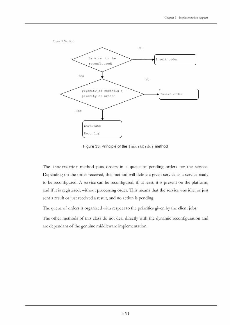
Chapter 5 - Implementation Aspects
InsertOrder:
Service to be
reconfigured?Insert order
Priority of reconfig >
priority of order?
No
Yes
Yes
SaveState
Reconfig!
Insert order
No
Figure 33. Principle of the InsertOrder method
The InsertOrder method puts orders in a queue of pending orders for the service.
Depending on the order received, this method will define a given service as a service ready
to be reconfigured. A service can be reconfigured, if, at least, it is present on the platform,
and if it is registered, without processing order. This means that the service was idle, or just
sent a result or just received a result, and no action is pending.
The queue of orders is organized with respect to the priorities given by the client jobs.
The other methods of this class do not deal directly with the dynamic reconfiguration and
are dependant of the genuine middleware implementation.
5-91
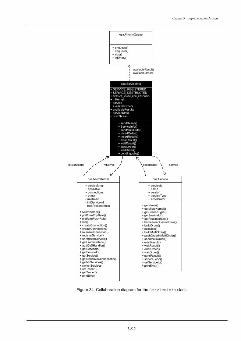
Chapter 5 - Implementation Aspects
osa.PriorityQueue
+ getName() + getMicroKernel() + getServiceType() + getServiceId() + getProcInterface() + kernelNeedControlFlow() + buildOrder() + buildJob() + buildMultiOrder() + pushOrderInMultiOrder() + sendMutliOrder() + existResult() + waitResult() + existOrder() + waitOrder() + sendResult() + serviceLoop() ~ selServiceId() # printError()
~ serviceId ~ name ~ version ~ serviceType ~ accelerator
osa.Service
+ sendResult() + ServiceInfo() ~ sendMultiOrder() ~ InsertOrder() ~ InsertResult() ~ existResult() ~ waitResult() ~ existOrder() ~ waitOrder() ~ pendingJobs()
+ SERVICE_REGISTERED + SERVICE_DESTRUCTED + SERVICE_ASKED_FOR_RECONFIG ~ mKernel ~ service ~ availableOrders ~ availableResults ~ serviceState ~ hostThread
osa.ServiceInfo
+ enqueue() ~ dequeue() ~ size() ~ isEmpty()
+ MicroKernel() + platformPopRule() + platformPushRule() + Init() + createConnection() + createConnection() + releaseConnection() + registerService() + unregisterService() + getProcInterface() + addQoSHandler() + getServiceId() + getServiceId() + getService() + getNbActiveConnections() + getNbServices() + switchServices() + setTracer() + getTracer() + printError()
~ serviceMngr ~ qosTable ~ connections ~ tracer - ruleResv - initServiceInf - taskProcInterface
osa.MicroKernel
availableResults availableOrders
initServiceInf mKernel accelerator service
Figure 34. Collaboration diagram for the ServiceInfo class
5-92
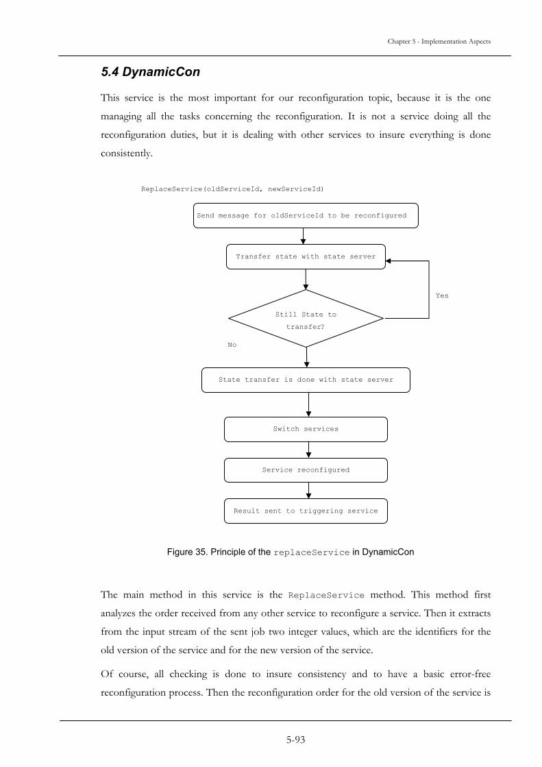
Chapter 5 - Implementation Aspects
5.4 DynamicCon
This service is the most important for our reconfiguration topic, because it is the one
managing all the tasks concerning the reconfiguration. It is not a service doing all the
reconfiguration duties, but it is dealing with other services to insure everything is done
consistently.
ReplaceService(oldServiceId, newServiceId)
Still State to
transfer?
State transfer is done with state server
Switch services
Transfer state with state server
No
Service reconfigured
Result sent to triggering service
Send message for oldServiceId to be reconfigured
Yes
Figure 35. Principle of the replaceService in DynamicCon
The main method in this service is the ReplaceService method. This method first
analyzes the order received from any other service to reconfigure a service. Then it extracts
from the input stream of the sent job two integer values, which are the identifiers for the
old version of the service and for the new version of the service.
Of course, all checking is done to insure consistency and to have a basic error-free
reconfiguration process. Then the reconfiguration order for the old version of the service is
5-93

Chapter 5 - Implementation Aspects
built, to request it to be set in a reconfigurable state. A connection is established via the
system to the old version of the service; and the order is sent. The DynamicCon then waits
for the result, if no error occurs, then DynamicCon proceeds to the state transfer. And at
last, the DynamicCon service sends to the service, which triggers the reconfiguration, the
result concerning the reconfiguration job – i.e. failure or success.
Figure 35 shows the structure of the DynamicCon service for the replaceService method
and Figure 36 shows the relationship between any service and the dynamic reconfiguration
service, DynamicCon.
Service
Figure 36. Collabo
+ getName() + getMicroKernel() + getServiceType() + getServiceId() + getProcInterface() + kernelNeedControlFlow() + buildOrder() + buildJob() + buildMultiOrder() + pushOrderInMultiOrder() + sendMutliOrder() + existResult() + waitResult() + existOrder() + waitOrder() + sendResult() + serviceLoop() ~ selServiceId() # printError()
~ serviceId ~ name ~ version ~ serviceType ~ accelerator
+ print() + checkError() + construct() + destruct() + replaceService() + getQoSCapabilities() + createService() + serviceLoop()
osa.DynamicCon
ration diagram for the DynamicCon service.
5-94

Chapter 5 - Implementation Aspects
5.5 StateServer
The StateServer is the service that is responsible for transferring all the state information
from one version of a service to another version.
Basically, there are two ways to deal with the state information of services:
1. The state information is stored inside the service. The StateServer accesses
this state information to transfer it.
2. The state information is stored inside the StateServer. The service accesses
this state information to operate.
While method 1 is the more natural way, it introduces several problems: the StateServer
would need references to all state variables inside the service, thus overhead is introduced.
Furthermore, it is hard to handle concurrent access to state variables by the StateServer
and by the service. Finally, for the non-blocking approach, it is essential to know the
remaining amount of state information to transfer. With respect to real-time properties and
memory overhead, this cannot be done by always comparing the current state variables with
previous versions. A more efficient way has to be found.
Therefore, we decided to use method 2. The drawback of this approach is a service has to
handle its state externally by accessing the StateServer. However, this drawback can be
solved in future by a compiler or pre-compiler automatically arranging the state information
of a service to the StateServer. On the other side, the approach to handle the state
information in the StateServer has a big advantage: It offers a very efficient
implementation, allows controlling concurrent requests and to maintain the amount of
remaining state information to transfer without compare or search operations.
Figure 37 shows the methods of this StateServer.
Since the state information is handled inside the StateServer, there are three methods to
access the state information by the application services. CreateStateVariable
dynamically creates a new state variable of a given type. As result, a reference to the newly
created variable is returned. Using this reference, the application service can access or
update the state variable using the functions GetStateVariable or
ChangeStateVariable. Id is a unique identifier for state variables. The idea behind this is
as follows: When updating an old service with a new version, the structure of the state
5-95
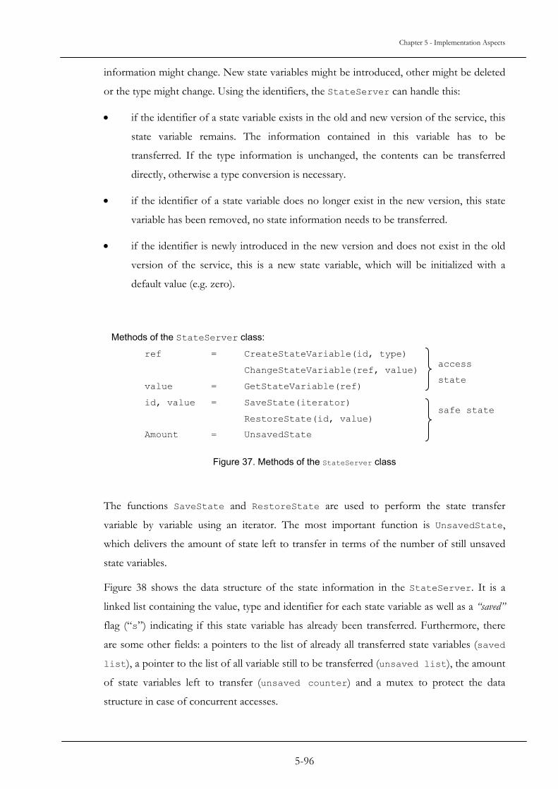
Chapter 5 - Implementation Aspects
information might change. New state variables might be introduced, other might be deleted
or the type might change. Using the identifiers, the StateServer can handle this:
• if the identifier of a state variable exists in the old and new version of the service, this
state variable remains. The information contained in this variable has to be
transferred. If the type information is unchanged, the contents can be transferred
directly, otherwise a type conversion is necessary.
• if the identifier of a state variable does no longer exist in the new version, this state
variable has been removed, no state information needs to be transferred.
• if the identifier is newly introduced in the new version and does not exist in the old
version of the service, this is a new state variable, which will be initialized with a
default value (e.g. zero).
Methods of the StateServer class: ref = CreateStateVariable(id, type)
ChangeStateVariable(ref, value)
value = GetStateVariable(ref)
id, value = SaveState(iterator)
RestoreState(id, value)
Amount = UnsavedState
safe state
access
state
Figure 37. Methods of the StateServer class
The functions SaveState and RestoreState are used to perform the state transfer
variable by variable using an iterator. The most important function is UnsavedState,
which delivers the amount of state left to transfer in terms of the number of still unsaved
state variables.
Figure 38 shows the data structure of the state information in the StateServer. It is a
linked list containing the value, type and identifier for each state variable as well as a “saved”
flag (“s”) indicating if this state variable has already been transferred. Furthermore, there
are some other fields: a pointers to the list of already all transferred state variables (saved
list), a pointer to the list of all variable still to be transferred (unsaved list), the amount
of state variables left to transfer (unsaved counter) and a mutex to protect the data
structure in case of concurrent accesses.
5-96

Chapter 5 - Implementation Aspects
Data Structure:
value, type
identifier “s” next
…
saved list
unsaved list
ref
unsaved counter
mutex
Figure 38. Data structure used in the StateServer class
The following enumeration shows how these functions cooperate and how the amount of
state variables left to transfer is maintained without compare operations:
• unsaved counter holds the number of the currently unsaved (untransferred)
state variables. It is initialized to 0 for a newly registered service.
• CreateStateVariable creates a new state variable and puts it into the top of
the unsaved list. The unsaved counter is incremented. The “s” (saved)
flag is cleared.
• ChangeStateVariable checks if the “s” flag is set. If so, the state variable is
moved from the saved list to the unsaved list. The “s” flag is then cleared
and unsaved counter is incremented.
• SaveState iterates through the unsaved list. It delivers state and identifier
of the next unsaved variable, puts it into the saved list, sets the “s” flag and
decrements the unsaved counter.
• UnsavedState returns the unsaved counter.
5-97

Chapter 5 - Implementation Aspects
• id identifies a state for state transfer. During transfer, a state variable from the
source is copied to the variable with the same id in the destination service.
The Figure 39 presents relationships between the StateServer and the related classes:
5-98

Chapter 5 - Implementation Aspects
Service osa.ServiceInfo
5
T
m
a
(
m
W
a
+ getName() + getMicroKernel() + getServiceType() + getServiceId() + getProcInterface() + kernelNeedControlFlow() + buildOrder() + buildJob() + buildMultiOrder() + pushOrderInMultiOrder() + sendMutliOrder() + existResult() + waitResult() + existOrder() + waitOrder() + sendResult() + serviceLoop() ~ selServiceId() # printError()
~ serviceId ~ name ~ version ~ serviceType ~ accelerator
+ print() + checkError() + construct() + destruct() + createStateVariable() + changeStateVariable() + getStateVariable() + saveState() + restoreState() + getQoSCapabilities() + serviceLoop()
osa.StateServer
+ sendResult() + ServiceInfo() ~ sendMultiOrder() ~ InsertOrder() ~ InsertResult() ~ existResult() ~ waitResult() ~ existOrder() ~ waitOrder() ~ pendingJobs()
+ SERVICE_REGISTERED + SERVICE_DESTRUCTED + SERVICE_ASKED_FOR_RECONFIG ~ mKernel ~ service ~ availableOrders ~ availableResults ~ serviceState ~ hostThread
+ print() + checkError() + construct() + destruct() + replaceService() + getQoSCapabilities() + createService() + serviceLoop()
osa.DynamicCon
Accelerator
Service
Figure 39 Collaboration between StateServer and related services.
.6 Conclusion
he implementation of the dynamic reconfiguration causes only minor changes in the
icrokernel (cf. 5.1 to 5.3). Most of the classes of the core of OSA+ are untouched. It was
main requirement to allow the system to operate as before. Most of the implementation
DynamicCon, StateServer) could be implemented as extension services to the
icrokernel.
ith all the implementation aspects, it was possible to obtain a working middleware
llowing dynamic real-time reconfiguration.
5-99

Chapter 6 Practical Evaluation
The purpose of an evaluation is to prove and to rate a conception. This can be done in a
theoretical and a practical way.
For our approach, we have decided to combine both ways. In the theoretical part described
in section 4.4 we have determined time bounds for the reconfiguration and blackout time
and the conditions for these bounds to hold. In this chapter, we will present an additional
practical evaluation to answer the following questions:
• how is the overall performance of our approach? How big are the reconfiguration- and
blackout-time on an average system?
• how big is the advantage of having a Reconfiguration Service (DynamicCon) instead of
letting the application services do the reconfiguration?
• and finally, what is the advantage of the job-based reconfiguration, where reconfiguration
orders compete with other orders according to their priority?
As evaluation environment, a standard PC has been chosen, running as operating-system
Microsoft Windows 2000, with the latest service pack available. Because worst-case time
bounds have been fixed in a theoretical way, we interested beside the minimum and
maximum performance especially in the average performance in a standard system. So this
system configuration is a good basis, no special real-time operating system is used. The
hardware part is based on an AMD XP1900+ which frequency is 1.6 GHz, and 1 GB of
RAM. The software part, except for the operating system, is composed by the Java
Development Kit 1.4.1. The development of our implementation was done with the normal
JDK classes, i.e. without using any Beans nor Swing classes. Of course, to have more
relevant experiments, they will be done later on a system with RTOS like RT-Linux or
VxWorks.
6-101

Chapter 6 - Practical Evaluation
6.1 Overall Performance To measure the overall performance of our approach, we created a simple test bed. The
system will have only the essential services launched. One service, ServiceBeta, will send
orders to two other services, named OldService and ReconfTrigger. This
ReconfTrigger service will trigger the reconfiguration of OldService by sending a
ReconfOrder to the platform. The order will be distributed to the DynamicCon service.
This one will initiate the reconfiguration process. Then the OldService will be replaced by
the NewService.
OldService and ReconfTrigger receive just orders to print a line on the standard output
(console mode). ReconfTrigger, after a defined amount of orders received, will trigger the
reconfiguration as explained above. Once the reconfiguration is done, while ServiceBeta
will still send orders to both services, but rather than having OldService executing the
orders, it will be NewService (cf. Figure 40).
ReconfTrigger
ServiceBeta
OldServiceresults
orders
results
reconfiguration order for OldService1
result
Triggers the
reconfiguration
NewVersion
oders
results
orders
initiates the reconfiguration
DynamicCon
Figure 40. Test bed for the reconfiguration of a service
The first result is without state transfer. Table 2 shows the average, maximum and
minimum blackout times. It represents 100 experiments and for each, 50 orders were sent.
A reconfiguration order is sent after 10 “normal orders” were sent. As it can be seen,
switching is performed quickly.
6-102
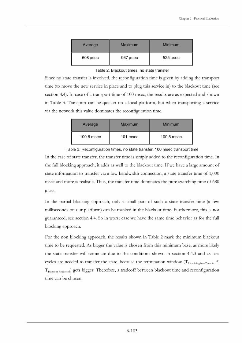
Chapter 6 - Practical Evaluation
Average Maximum Minimum
608 µsec 967 µsec 525 µsec
Table 2. Blackout times, no state transfer
Since no state transfer is involved, the reconfiguration time is given by adding the transport
time (to move the new service in place and to plug this service in) to the blackout time (see
section 4.4). In case of a transport time of 100 msec, the results are as expected and shown
in Table 3. Transport can be quicker on a local platform, but when transporting a service
via the network this value dominates the reconfiguration time.
Average Maximum Minimum
100.6 msec 101 msec 100.5 msec
Table 3. Reconfiguration times, no state transfer, 100 msec transport time
In the case of state transfer, the transfer time is simply added to the reconfiguration time. In
the full blocking approach, it adds as well to the blackout time. If we have a large amount of
state information to transfer via a low bandwidth connection, a state transfer time of 1,000
msec and more is realistic. Thus, the transfer time dominates the pure switching time of 680
µsec.
In the partial blocking approach, only a small part of such a state transfer time (a few
milliseconds on our platform) can be masked in the blackout time. Furthermore, this is not
guaranteed, see section 4.4. So in worst case we have the same time behavior as for the full
blocking approach.
For the non blocking approach, the results shown in Table 2 mark the minimum blackout
time to be requested. As bigger the value is chosen from this minimum base, as more likely
the state transfer will terminate due to the conditions shown in section 4.4.3 and as less
cycles are needed to transfer the state, because the termination window (TRemainingStateTransfer ≤
TBlackout Requested) gets bigger. Therefore, a tradeoff between blackout time and reconfiguration
time can be chosen.
6-103

Chapter 6 - Practical Evaluation
6.2 Advantages of introducing the Reconfiguration Service Basically, there are two ways to handle the reconfiguration. One would be to do the
reconfiguration by the service requesting it using functionality of the microkernel. The other
way, our approach, is to introduce a special extension service for this purpose, the
Reconfiguration Service (DynamicCon). To evaluate the advantages of this approach, let’s
recall the scenario from Figure 40.
The ReconfTrigger service is triggering the reconfiguration. At the same time, this
service is receiving orders by ServiceBeta. Alternativly to our approach, we have
implemented a version where ReconfTrigger does the reconfiguration on its own without
using DynamicCon. Table 4 shows as result the blackout time of ReconfTrigger, this
means the time this service does not react to orders sent by ServiceBeta. The state
transfer time was set to 2,000 msec in this experiment. As it can be seen, the blackout time
using DynamicCon is much shorter, because DynamicCon cares for the state transfer. In the
other case, ReconfTrigger is bothered with this task leading to a big blackout.
Case With DynamicCon Without DynamicCon
Blackout Time in µseconds for the service triggering
the reconfiguration 608 µsec 2,007,906 µsec
Table 4. Comparison of a reconfiguration with and without DynamicCon
This shows that a reconfiguration by switching a working service with another one, with the
help of a dedicated service is more efficient than by doing the reconfiguration internally by
the triggering service itself.
6.3 Priority experiment To evaluate the influence of job-based reconfiguration including priorities, we modified the
above experiment. Rather than to send the reconfiguration order with the same priority as
the others, we made several tests, with different value for the reconfiguration order priority.
Like for the other experiments, we repeated this experiment several times to exclude any
random results. Only the orders sent to the OldService service got different priority
values. In our first priority test, all orders are sent with a priority value of 5, which is an
average value. As all orders have the same priority, they are all processed one after the
other. After the reconfiguration, the NewService will process the orders sent to
OldService.
6-104

Chapter 6 - Practical Evaluation
Second, we decided to give to the reconfiguration order the highest possible priority value,
which is 0. This means that the OldService will process the reconfiguration order before
following orders. Since the reconfiguration order is placed in the order queue of
OldService before the other orders.
At last, we gave to the reconfiguration order the lowest possible priority value, which in our
case is 15. This means that during the time laps orders are placed in the order queue of
OldService, if normal orders are received before the reconfiguration order is processed,
these orders will be executed before the reconfiguration order.
Table 5 shows a log from our experiment, with the slots marked where the reconfiguration
order is received by DynamicCon and where the reconfiguration is finally executed. Figure
41 summarizes the results in a graphic.
Sequential order First Experiment Second Experiment Third Experiment
… … … …
19 *-* order received by
OldService
*-* order received by
OldService
*-* order received by
OldService
20 *** order received by
ReconfTrigger
*** order received by
ReconfTrigger
*** order received by
ReconfTrigger
21 *-* order received by
OldService
*-* order received by
OldService
*-* order received by
OldService
22 --- order received by
DynamicCon
--- order received by
DynamicCon
--- order received by
DynamicCon
23 *** order received by
ReconfTrigger
*** order received by
ReconfTrigger
*** order received by
ReconfTrigger
24 *-* order received by
OldService
*-* order received by
OldService
*-* order received by
OldService
25 -*- order received by
NewService
-*- order received by
NewService
*** order received by
ReconfTrigger
26 *** order received by
ReconfTrigger
*** order received by
ReconfTrigger
*-* order received by
OldService
27 -*- order received by
NewService
-*- order received by
NewService
*** order received by
ReconfTrigger
28 *** order received by
ReconfTrigger
*** order received by
ReconfTrigger
*-* order received by
OldService
29 -*- order received by
NewService
-*- order received by
NewService
*** order received by
ReconfTrigger
6-105

Chapter 6 - Practical Evaluation
30 *** order received by
ReconfTrigger
*** order received by
ReconfTrigger
*-* order received by
OldService
31 -*- order received by
NewService
-*- order received by
NewService
*** order received by
ReconfTrigger
32 *** order received by
ReconfTrigger
*** order received by
ReconfTrigger
*-* order received by
OldService
33 -*- order received by
NewService
-*- order received by
NewService
*** order received by
ReconfTrigger
34 *** order received by
ReconfTrigger
*** order received by
ReconfTrigger
*-* order received by
OldService
35 -*- order received by
NewService
-*- order received by
NewService
-*- order received by
NewService
36 *** order received by
ReconfTrigger
*** order received by
ReconfTrigger
*** order received by
ReconfTrigger
37 -*- order received by
NewService
-*- order received by
NewService
-*- order received by
NewService
38 *** order received by
ReconfTrigger
*** order received by
ReconfTrigger
*** order received by
ReconfTrigger
… … … …
Table 5. Priority log
6-106

Chapter 6 - Practical Evaluation
New Service
Old Service
5 10 15 20 25 30 35 40 45 order processed
Experiment 1: same priorities for all orders
New Service
Old Service
5 10 15 20 25 30 35 40 45 order processed
Experiment 2: reconfiguration order has higher priority
New Service
Old Service
5 10 15 20 25 30 35 40 45 order processed
Experiment 3: reconfiguration order has lower priority
reconfiguration requested
Figure 41. Different priorities of the reconfiguration job
It can be seen, that there is no difference between the first experiment, where all orders
have the same priority, and the second experiment, where the reconfiguration order has the
higher priority. This happens, because the reconfiguration order arrives before the next
regular order. So regardless if the priority of the reconfiguration order is equal or higher
compared to the next order, it is executed first.
This is different, if the reconfiguration order has a lower priority, like in experiment 3. As it
can be seen in the figure, the reconfiguration is delayed. In that case, the higher priority
regular orders overtake the reconfiguration order and are executed first.
This experiment shows, that using job-based reconfiguration including priorities allows a
smooth integration of the reconfiguration in the overall real-time processing.
6-107

Chapter 6 - Practical Evaluation
6.4 Summary Concluding this practical evaluation it is to mention, that it has to be seen as a supplement
to the theoretical part. It is hard to generate a generic workload. As it has been shown, the
state transfer time can easily become the dominating part for the reconfiguration time for all
presented approaches and as well for the blackout time off the full blocking and partial
blocking approach. Switching time and therefore the blackout time for the non blocking
approach can be fast. The state transfer terminates, if the conditions defined in chapter
4.4.3 are met. As longer the allowed blackout time is given, as easier it is to hold these
conditions and to shorten the reconfiguration time.
Due to some time restrictions, it was not possible to do more practical evaluations before
writing this thesis. Nevertheless, the presented results show the feasibility of our approach.
6-108

7-109
Chapter 7 Conclusion and Future Work
7.1 Conclusion
A middleware is something complex by itself and due to its nature: it is a piece of software,
which allow and ease other software to communicate and to interact with each other, nearly
transparently, and whatever the environment, the language, the operating system are. It is an
interconnected heterogeneous world.
The purpose of this PhD thesis was to design, conceive and evaluate a middleware-based
dynamically reconfigurable architecture for distributed real-time systems. Since it should be
suitable for embedded systems with low resources too, we put our approach on top of
OSA+, a microkernel middleware architecture especially designed for embedded systems.
The main contributions of this thesis can be listed as follows:
• a job-based reconfiguration scheme has been introduced allowing reconfiguration jobs
to compete with all other jobs in the system according to priorities (or deadlines). This
scheme integrates the reconfiguration process in the real-time operation of the other
system tasks.
• a Reconfiguration Service takes the reconfiguration load from the application services.
Reconfiguration can be handled in an asynchronous way, the application service
triggering the reconfiguration is not blocked nor has to wait for the end of the
reconfiguration.
• three approaches regarding the state transfer problem have been introduced. Especially
the non blocking approach allows to transfer the state of a service while this service is
still running. This reduces the blackout time, in fact a blackout time can be requested.
A trade-off between the blackout time and the reconfiguration time is possible
• upper bounds for the reconfiguration time and the blackout time have been calculated.
In case of the non-blocking approach, conditions for the termination of the state
transfer have been given.

Chapter 7 - Conclusion and Future Work
• an efficient implementation to maintain and monitor the remaining state information
to transfer in case of the non blocking approach has been given.
• finally, the reconfiguration concept has been integrated and implemented in a full
microkernel service oriented middleware architecture suitable for embedded systems.
7.2 Future Work
The current implementation is a prototype with only the basic necessary functionality
implemented. To make it a mature system, more implementation work has to be done.
Furthermore, next steps will be to implement, test and evaluate our system on different
heterogeneous hardware platforms and operating systems like e.g. VxWorks or Komodo.
At last, it will be time to give a real application a chance, with our middleware. The system
will be embedded on a automated guided vehicle, which will move thanks to various
sensors.
Our work does not concern the load balancing, but it may be a next research step to
evaluate to improve the reconfigurability of the middleware for embedded system, though it
should not interfere with the real-time requirements of the system.
Finally, organic computing is a new research focus dealing with self-x properties of
computational systems like self-organizing, self-configuring, self-healing, self-protecting, etc.
Some of these feature could be realized by dynamic reconfiguration on the middleware
level, e.g. the automatic relocation of services when a component fails (self-healing). One or
more organic managers could observe the system and reconfigure it according to the
current needs.
7-110

Bibliography
[1] D.C. Schmidt, R&D Advances in Middleware for Distributed Real-Time and Embedded Systems,C|Net, 2002.
[2] C.R. Hofmeister, Dynamic Reconfiguration of Distributed Applications, Thesis, 1993.
[3] “IBM Websphere Software”, (1994-2004), IBM Websphere Application Server, available: http://www.ibm.com/websphere, (accessed: 15th of October, 2004) .
[4] Novell, Programming a Distributed Application The TUXEDO® System Approach,Novell, 1993.
[5] J. Allaire and JJ. Allaire, (1995), “ColdFusion”, Macromedia, available: http://www.macromedia.com/software/coldfusion/, (accessed: 3rd of October, 2004).
[6] “ObjectWeb”, (1999-2004), available: http://www.objectweb.org/, (accessed: 6th of October, 2004).
[7] University of Illinois, Glossary, 2004.
[8] “DCE Portal”, (15th of June, 2004), The Open Group, available: http://www.osf.org/dce/, (accessed: 14th of July, 2004).
[9] “DCOM Technical Overview”, (1997-2004), Microsoft, available: http://msdn.microsoft.com/library/default.asp?url=/library/en-us/dndcom/html/msdn_dcomtec.asp, (accessed: 23rd of September, 2004).
[10] “The Common Object Request Broker: Architecture and Specification”, (February 1998), Object Management Group, available: http://www.omg.org, (accessed: 15th of June, 2004).
[11] “FAQ”, (1998-2004), comp.realtime newsgroup, available: nntp://comp.realtime, (accessed: 3rd of November, 2004).
[12] P.A. Laplante, Real-Time Systems Design and Analysis, An Engineer's Handbook, IEEE Press, 1997.
[13] J. Magee and J. Kramer, Dynamic Configuration for Distributed Real-Time Systems, Arlington, Viginia, USA, 1983.
[14] S. Gaa, Autonomous Vehicle Controlled by the Komodo Microcontroller,University of Karlsruhe - IPR Prof. Brinkschulte, Sion, 2004.
[15] Object Management Group, OMG's Object Management Architecture, http://www.omg.org, 2004.
[16] Object Management Group, CORBA FAQ, http://www.omg.org, 2004.
[17] J.M. Grochow, Overload: Creating Value with The New Information Systems Technology,Yourdon Press/Prentice Hall, 1997.
111

Bibliography
112
[18] D.S. Linthicum, Reevaluating Distributed Objects, Vol. 10, Miller Freeman, Inc., 1997.
[19] F. Golatowski, J. Hildebrandt and D. Timmermann, Rapid Prototyping with Reconfigurable Hardware for Embedded Hard Real-Time Systems, Madrid, Spain, 1998.
[20] J. Stankovic, M. Spuri, K. Ramamritham and G. Buttazzo, Deadline Scheduling for Real-Time Systems,Springler, 1998.
[21] C. Liu and J. Layland, Journal of the Association for Computing Machinery, 20 (1973).
[22] Object Management Group, Real-time CORBA Specification,Object Management Group, http://www.omg.org, 2002-2004.
[23] D.C. Schmidt and F. Kuhns, An Overview of the Real-Time CORBA Specification, in Computer, 33#6, 2000.
[24] F. Kon, M. Roman, P. Liu, J. Mao, T. Yamane, L.C. Magalhães and R.H. Campbell, Monitoring, Security, and Dynamic Configuration with the DynamicTAO Reflective ORB, Springer-Verlag, New York, NY, USA, 2000.
[25] D.C. Schmidt and C. Cleeland, Applying Patterns to Develop Extensible ORB Middleware, in IEEE Communications Magazine Special Issue on Design Patterns, 1999.
[26] F. Picioroaga, A. Bechina, U. Brinkschulte and E. Schneider, OSA+ Real-Time Middleware, Results and Perspectives., Vienna, Austria, 2004.
[27] V. Tosic, D. Mennie and B. Pagurek, Software Configuration Management Related to Management of Distributed Systems and Services and Advanced Service Creation, Toronto, Canada, 2001.
[28] P.M. Melliar-Smith, L.E. Moser, V. Kalogeraki and P. Narasimhan, Realize: Resource Management for Soft Real-Time Distributed Systems,IEEE, 1999.
[29] M.A. Wermelinger, Specification of Software Architecture Reconfiguration, Thesis, 1999.
[30] P. Tröger and A. Polze, Object and Process Migration in .NET, Workshop on Object-oriented Real-time Dependable Systems, Guadalajara, Mexico, 2003.
[31] M. Pfeffer and T. Ungerer, Dynamic Real-Time Reconfiguration on a Multithreaded Java-Microcontroller,IEEE International Symposium on Object-oriented Real-time distributed Computing, Vienna, Austria, 2004.
[32] F. Picioroaga, Scalable and Efficient Middleware for Real-Time Embedded Systems. A Uniform Open Service Oriented Microkernel Based Architecture, Université Louis Pasteur Strasbourg I, Strasbourg, France, 2004.

Publications
1 E. Schneider, F. Picioroagă, U. Brinkschulte: Dynamic Reconfiguration through OSA+, a Real-Time Middleware, Middleware 04, 1st Middleware Doctoral Symposium, 2004, 18th-22nd October 2004, ACM, Toronto, Canada
2 A. Bechina, U. Brinkschulte, F. Picioroagă, E. Schneider: OSA+ Real-Time Middleware. Results and Perspectives. International Symposium on Object-Oriented Real-Time Distributed Computing (ISORC 2004), Wien, Austria, May 12 - 14, 2004.
3 U. Brinkschulte, A. Bechina, F. Picioroagă, E. Schneider: Open System Architecture for embedded control applications Concepts and results. To be published in ICIT'03 International Conference on Industrial Technology, Maribor, Slovenia, December 10 - 12, 2003, IEEE.
4 U. Brinkschulte, A. Bechina, B. Keith, F. Picioroagă, E. Schneider: A Middleware Architecture for Ubiquitous Computing Systems with Real-Time needs. 2002 IAR Workshop (Institute for Automation and robotic Research), Grenoble, France, November 23-24, 2002
5 U. Brinkschulte, A. Bechina, F. Picioroagă, E. Schneider: Distributed Real-Time Computing for Microcontrollers - the OSA+ Approach. International Symposium on Object-Oriented Real-Time Distributed Computing (ISORC 2002), Washington D.C., 2002, IEEE, p.169-172. ISBN: 0-7695-1558-4
6 U. Brinkschulte, A. Bechina, F. Picioroagă, E. Schneider & Th. Ungerer, J. Kreuzinger, M. Pfeffer: A Micro-kernel Middleware Architecture for Distributed Embedded Real-Time Systems. 20th Symposium on Reliable Distributed Systems, New Orleans, MI, USA, October 28-31, 2001, IEEE, p.218-226, ISBN: 0-7695-1366-2.
113

Publications
114
7 Bechina, U. Brinkschulte, F. Picioroagă, E. Schneider: Real Time middleware for industrial embedded measurement and control application OSA+. The 2001 International Conference on Parallel and Distributed Processing Techniques and Applications, Las Vegas, Nevada, USA, June 25-28, 2001, CSREA, p.843-849, ISBN: 1-892512-69-6.

Vita
Vita
Etienne Schneider [email protected]
Personal Information Marital Status: Married, one son Military Status : military period
completed (1997-1998) Nationality: French Date of birth : November, the 10th 1971
Summary of qualifications and Education
2000- PhD Thesis candidate at the IPR Laboratory in Karlsruhe, Germany.
The subject is the Dynamic Reconfiguration of a real-time middleware during run-time.
1999 Université Louis Pasteur – Strasbourg I Strasbourg, France
“DEA d’Informatique”, an equivalent of a Master in Computer Sciences degree, ended by a 5 months training period at the LIIA - Laboratoire d’Informatique et d’Intelligence Artificielle The objective of the training period was related to the Representation of Temporal Knowledge in Description Logics. – Java
1997 Université Louis Pasteur – Strasbourg I Strasbourg, France
I passed the "DESS d’Informatique" degree which should corresponds to a Senior Level degree (I learnt : AI, Pictures treatment, Network architecture, Environment, OOP). – Delphi, VB, C++
1996 Université Jules Verne de Picardie – Amiens Amiens, France
I passed the "Maîtrise en Méthodes Informatiques Appliquées à la Gestion des Entreprises " degree which should regroup knowledge about marketing, accountancy, programming techniques, enterprise management. Its purpose is to make programmers able to understand the enterprise management world.
1994 Institution Sainte Clotilde – Strasbourg Strasbourg, France
“Brevet de Technicien Supérieur en Comptabilité-Gestion”, which is a degree done in two years after the baccalauréat (end of senior high-school degree). The topic was about Accountancy and Management.
1991 Institution Sainte Clotilde – Strasbourg Strasbourg, France
115

Vita
“Baccalauréat G2 – Techniques Quantitative de Gestion”, which is a degree done at the end of senior high-school. The topic was about Accountancy and Management.
Professional experience and University’s projects
1998 Concept Strasbourg, France
I worked for that company for 2.5 months, after the military period and just before the “DEA”‘s courses. I used Microsoft Visual C++ for their Accountancy software - Comptawin - main task : solve the Euro problem. – C.
1997 TEPRAL – Groupe Kronenbourg Strasbourg, France
I worked for the TEPRAL a Research Center of the Groupe Danone, developping 3 projects, one of them was a CGI used in conjuction with JavaScript, to conceive dynamic questionnaires about beers on Windows NT. That was my trainee period. After that the TEPRAL hired me in purpose to manage the Intranet network, for a month, before my military period. – VB and VBA.
1995-1996 CDDP de Picardie Amiens, France
Designing a program for young children in the first years of school teaching them the basis of the school procedures (ie : to number, to read a map, to find the right/wrong word,...). – VB.
1995 Infor Conseils La Wantzenau, France
Correcting and updating Domus, a program written in MOS a French computer language, designed for the real estate agencies manager on PC computers. This in the Y2K and Euro objectives. – MOS.
116
Top Related