


Languages
Pages
Legal

C A R B O N 6 2 ( 2 0 1 3 ) 2 8 8 – 2 9 5
.sc iencedi rect .com
Avai lab le at wwwjournal homepage: www.elsev ier .com/ locate /carbon
A high-capacity lithium–air battery with Pdmodified carbon nanotube sponge cathodeworking in regular air
0008-6223/$ - see front matter � 2013 Elsevier Ltd. All rights reserved.http://dx.doi.org/10.1016/j.carbon.2013.05.066
* Corresponding authors: Fax: +86 27 87558241 (Y. Huang).E-mail address: [email protected] (Y. Huang).
1 These authors contributed equally to this work.
Yue Shen a,1, Dan Sun a,1, Ling Yu a, Wang Zhang a, Yuanyuan Shang b, Huiru Tang c,Junfang Wu c, Anyuan Cao b,*, Yunhui Huang a,*
a State Key Laboratory of Material Processing and Die & Mould Technology, School of Materials Science and Engineering,
Huazhong University of Science and Technology, Wuhan, Hubei 430074, Chinab Department of Materials Science and Engineering, College of Engineering, Peking University, Beijing 100871, Chinac State Key Laboratory of Magnetic Resonance and Atomic and Molecular Physics, Wuhan Institute of Physics and Mathematics,
Chinese Academy of Sciences, Wuhan 430071, China
A R T I C L E I N F O A B S T R A C T
Article history:
Received 8 February 2013
Accepted 29 May 2013
Available online 13 June 2013
We report a lithium–air battery with a free-standing, highly porous Pd-modified carbon
nanotube (Pd–CNT) sponge cathode. The Pd-CNT sponge was synthesized through a chem-
ical vapor deposition growth followed with an electrochemical deposition process. To build
a whole lithium–air battery, the air cathode is integrated with a ceramic electrolyte-pro-
tected lithium metal anode and non-volatile ionic liquid electrolyte. The lithium anode is
stable during the operation and long-time storage and the ionic liquid is chemically inert.
By controlling the amount of ionic liquid electrolyte, the sponge is wet but not fulfilled by
the electrolyte. Such configuration offers a tricontinuous passage for lithium ions, oxygen
and electrons, which is propitious to the discharge reaction. In addition, the existence of Pd
nanoparticles improves the catalytic reactivity of the oxygen reduction reaction. The bat-
tery is durable to any humidity level and delivers a capacity as high as 9092 mA h g�1.
� 2013 Elsevier Ltd. All rights reserved.
1. Introduction
The lithium–air battery is receiving world-wide interest be-
cause its theoretical specific energy far exceeds the best of
lithium-ion batteries [1–5]. By carefully designing the porosity,
conductivity and catalytic reactivity of the air cathode, the
cathode capacity of the lithium–air battery with organic elec-
trolyte can reach 15000 mA h g�1 [6]. However, the lithium–air
battery is still far from practical application due to a lot of
problems such as low discharge rate, poor cyclability and
rigorous operation condition [7]. Most of the organic
electrolyte lithium–air batteries have to be operated in pure
oxygen atmosphere to avoid the fast oxidation of the lithium
anode in humid air [8–12]. Aqueous electrolyte lithium–air
batteries with ceramic electrolyte (lithium super ionic con-
ductor, LiSICON [13]) protected anode have been developed
to overcome this disadvantage [14–20]. Nevertheless, the en-
ergy density of an aqueous electrolyte battery is much lower
than the organic electrolyte system [21]. And the evaporation
of the aqueous electrolyte in open air condition is always a
problem. All solid-state lithium–air battery with LiSICON
powder as the cathode electrolyte is an optional choice
[22,23], but the ionic conductivity at the grain boundary of
the LiSICON powder is usually too low. Obtaining high

C A R B O N 6 2 ( 2 0 1 3 ) 2 8 8 – 2 9 5 289
capacity in regular air instead of pure oxygen or saturated
water vapor is a very important direction for development
of lithium–air batteries. A very recent work took advantage
of the p–p interaction between imidazolium ions and single-
walled carbon nanotubes to form a hydrophobic gel air cath-
ode and obtained a capacity as high as 10730 mA h g�1 at 50%
relative humidity (RH), which is very encouraging [24].
In this work, we report a novel lithium–air cathode with a
free-standing, highly porous and catalytic active Pd–modified
carbon nanotube (Pd–CNT) sponge. The air cathode is inte-
grated with a ceramic electrolyte-protected lithium metal an-
ode and non-volatile ionic liquid electrolyte. The battery
design makes it durable to any humidity level and delivers a
capacity as high as 9092 mA h g�1.
2. Experimental
2.1. Synthesis of the carbon nanotube sponges
The carbon nanotube (CNT) sponges were synthesized by
chemical vapor deposition (CVD) process [25]. Ferrocene in
dichlorobenzene solution (0.06 g ml�1) was continuously in-
jected into a 2-inch quartz tube housed in a resistive furnace
by a syringe pump at a feeding rate of 0.13 ml min�1. The
reaction temperature was set at 860 �C. Carrier gas, a mixture
of Ar and H2, was flowing at a rate of 2000 and 300 ml min�1,
respectively. A 2 inch · 1 inch quartz sheet was placed in the
reaction zone as the growth substrate. The sponge-like prod-
ucts were collected from the quartz substrate after CVD,
which reached a thickness of about 0.3 mm for a growth per-
iod of 1 h.
2.2. Electrochemical deposition of the noble metal catalyston the CNT sponges
As synthesized CNT sponges were immersed in a PdCl2(3.3 mg ml�1), HCl (0.1 mol l�1), polyethylene oxide (PEO, mol-
ecule weight � 600,000, 30 mg ml�1) aqueous solution. Two
pieces of the CNT sponges were set as the anode and cathode,
respectively, for the electrochemical deposition. The current
density was set at 0.302 mA mg�1 (carbon) for 10 min to make
the weight ratio between the Pd and CNT equal to 1:10. After
the deposition, the samples were washed with DI water and
were heated to 350 �C for 4 h in Ar–H2 atmosphere (5% H2,
pressure = 15 atm) to eliminate the PEO residue.
2.3. Assembly of the lithium–air battery
Copper current collect, Li–metal disk (1 mm thick), Celgard
3501 porous polymer separator immersed with LiTFSI–
PP13TFSI (0.3 mol kg�1, from Shanghai Chengjie Chemical
Co. Ltd.) and LiSICON plate (thickness = 150 lm, from Ohara
Inc.) were assembled layer by layer in the argon-filled glove
box. Epoxy resin was used as the seal around the edge of
the assembled anode. After that, the anode part was taken
out of the glove box. The Pd–CNT sponge (thickness = 0.3 mm)
was wetted with the ionic liquid electrolyte (30–40% volume
ratio) and put onto the LiSICON surface as the cathode. No
binder was used. The average loading density of the CNT
sponge (including noble metal catalyst) was about 1 mg cm�2.
Nickel foam was put on top of the CNT sponge as the cathode
current collector. The whole cathode was directly exposed in
the open air.
2.4. Electrochemical measurements
The cells were tested in a special blasting drying oven in
which there were cables connected to the battery tester. The
RH outside the oven was controlled with a humidity sensor,
a humidifier and a dehumidifier and the temperature outside
the oven was maintained at 25 �C with an air-conditioner. To
test the discharge performance in RH = 0% condition, the cell
was put in a beaker which had cotton and CaO powder above
the cell. The cells were discharged to 2.0 V to measure the ini-
tial capacity. To test the cyclability at low discharge depth, the
cells were firstly discharged to 2000 mA h g�1 and then cycled
at 1000 mA h g�1. The specific capacity was calculated by the
mass of the whole cathode (Pd + CNT). The electrochemical
impedance spectroscopy (EIS) of the cells was also measured
in the blasting drying oven at the working condition. The fre-
quency range applied was from 1 MHz to 30 mHz at potentio-
static signal amplitudes of 10 mV.
2.5. SEM, TEM, XRD characterizations
The morphology of the air cathode was observed with scan-
ning electron microscope (SEM, SIRION200) before and after
discharge. Transmission electron microscopy (TEM) observa-
tion was carried out on a JEOL 2100F microscope. The dis-
charge product was characterized by X-ray diffraction (XRD,
PANalytical B.V., Holland).
2.6. NMR analysis of the electrolyte
To prepare the sample, the whole air cathode with electrolyte
was soaked into dimethyl sulfoxide-D6 containing 0.03% tet-
ramethylsilane (Cambridge Isotope Laboratories, Inc.) to
make a solution. All 1H NMR (nuclear magnetic resonance)
spectra were acquired at 298 K on a Bruker AVIII 600 MHz
spectrometer equipped with an inverse cryoprobe using a sin-
gle pulse sequence with a recycle delay of 2.0 s (RD-90�-AQ).
Sixteen transients were collected into 32000 data points for
each spectrum with a spectral width of 20 ppm. 19F NMR spec-
tra were acquired with a single pulse sequence (RD-90�-AQ)
on a home-build 500 MHz spectrometer equipped with an
OneNMR probe (Varian Inc.). The 90� pulse length was 7.8 s
and 16 transients were also collected into 32 k data points
with a spectral width of 30 ppm.
3. Results and discussion
3.1. Battery configuration
Our battery design has overlapping features from both the or-
ganic electrolyte design and the aqueous electrolyte design.
The basic principle is like the organic electrolyte design: the
lithium ions come from the lithium metal anode transport
through the electrolytes to the porous air cathode and react

Fig. 2 – Photo of the lithium metal anode taken from the
battery after discharge–charge and 2 months storage.
290 C A R B O N 6 2 ( 2 0 1 3 ) 2 8 8 – 2 9 5
with the oxygen to form solid state discharge products;
whereas a ceramic lithium super ionic conductor (LiSICON)
plate was added in between the cathode and the anode, like
the aqueous electrolyte design, to protect the lithium metal
anode (Fig. 1). With this design, the lithium metal anode is to-
tally isolated from the oxygen and water in the air. So it is sta-
ble during the operation and longtime storage. Fig. 2 shows
that the surface of the lithium metal anode was still shiny
after discharge–charge and 2 months storage. (If the lithium
metal is exposed in humid air, the surface will become dark
after a few minutes.)
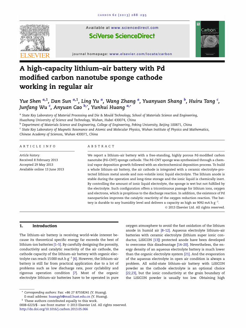
3.2. Structure of the Pd–CNT sponge
To meet the need for a conductive, catalytically active porous
framework of the air cathode, we synthesized Pd–CNT
sponges (Fig. 3) by CVD growth and electrochemical deposi-
tion. The CNT sponge [25,26] is a free-standing sponge-like
bulk material consisting of self-assembled, interconnected,
highly conductive (conductivity = 0.5–1 S cm�1) multi-walled
CNT skeletons, with a density close to the aerogels (den-
sity = 5–10 mg cm�3), porosity of more than 99% and average
pore size of 80 nm [25]. Besides, unlike other carbon nanotube
or carbon nanofiber materials that have a natural tendency to
aggregation and entanglement, the loose structure of CNT
sponge is quite robust. Its surface area is not so large (300–
400 m2 g�1) [25] comparing with active carbon (higher than
2000 m2 g�1) but the surface area is mainly from the macrop-
ores instead of micropores in active carbons. Considering the
solid product will easily fulfill the micropores in the discharge
process, the surface area from micropores is not important.
To improve its catalysis reactivity, traditional oxygen reduc-
tion reaction (ORR) catalyst Pd nanoparticles were deposited
on the surface of the CNT through electrochemical process.
The morphologies are shown in Fig. 3a and b. Comparing
Fig. 3b and c, we can see the Pd particles on the CNTs. The
uniform coating of Pd nanoparticles is also confirmed by en-
ergy dispersive X-ray spectroscopy (EDX) and elemental map-
ping image, as shown in Fig. 3e. The EDX-measured weight
Fig. 1 – Scheme of the battery configurat
ratio of Pd to C is 1:18. The observed Fe signal comes from
the catalyst used in the CNT growth process.
3.3. Liquid electrolyte selection
Ionic liquid lithium bis(trifluoromethylsulfonyl)imide (LiTFSI)
in N-propyl-methyl-piperidinium-bis(trifluoromethylsulfo-
nyl)imide (PP13TFSI) solution (0.3 mol kg�1) was chosen as
the cathode electrolyte. This electrolyte has a very low vapor
pressure so that it will never dry out. It has excellent wettabil-
ity to the graphitic carbon surface. Since it is impossible to
measure the contact angle of the ionic liquid on CNT sponge,
we measured the contact angle of the ionic liquid on a com-
pressed graphite pellet surface that also consists of sp2 C
atoms, as displayed in Fig. 4. And more importantly, it doesn’t
contain ether or carbonate group which are easily attacked by
the nucleophilic O2� and decomposes [27–29]. The only possi-
ble point to be attacked by O2� in PP13TFSI is the N atom in
the center of the PP13 cation. However, since the alkyl groups
bonded to the N atom are very poor leaving groups, there
won’t be any reaction. It should be mentioned that dimethyl
sulfoxide (DMSO) based electrolytes could also be an optional
ion before (a) and after (b) discharge.
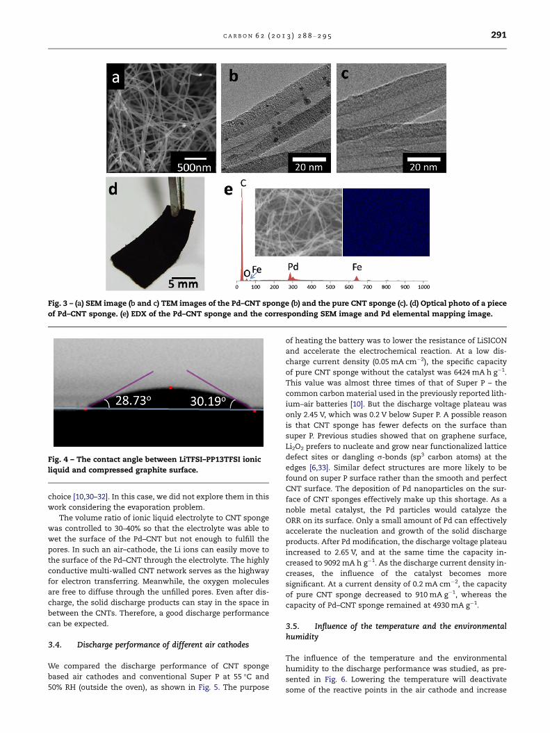
Fig. 3 – (a) SEM image (b and c) TEM images of the Pd–CNT sponge (b) and the pure CNT sponge (c). (d) Optical photo of a piece
of Pd–CNT sponge. (e) EDX of the Pd–CNT sponge and the corresponding SEM image and Pd elemental mapping image.
Fig. 4 – The contact angle between LiTFSI–PP13TFSI ionic
liquid and compressed graphite surface.
C A R B O N 6 2 ( 2 0 1 3 ) 2 8 8 – 2 9 5 291
choice [10,30–32]. In this case, we did not explore them in this
work considering the evaporation problem.
The volume ratio of ionic liquid electrolyte to CNT sponge
was controlled to 30–40% so that the electrolyte was able to
wet the surface of the Pd–CNT but not enough to fulfill the
pores. In such an air–cathode, the Li ions can easily move to
the surface of the Pd–CNT through the electrolyte. The highly
conductive multi-walled CNT network serves as the highway
for electron transferring. Meanwhile, the oxygen molecules
are free to diffuse through the unfilled pores. Even after dis-
charge, the solid discharge products can stay in the space in
between the CNTs. Therefore, a good discharge performance
can be expected.
3.4. Discharge performance of different air cathodes
We compared the discharge performance of CNT sponge
based air cathodes and conventional Super P at 55 �C and
50% RH (outside the oven), as shown in Fig. 5. The purpose
of heating the battery was to lower the resistance of LiSICON
and accelerate the electrochemical reaction. At a low dis-
charge current density (0.05 mA cm�2), the specific capacity
of pure CNT sponge without the catalyst was 6424 mA h g�1.
This value was almost three times of that of Super P – the
common carbon material used in the previously reported lith-
ium–air batteries [10]. But the discharge voltage plateau was
only 2.45 V, which was 0.2 V below Super P. A possible reason
is that CNT sponge has fewer defects on the surface than
super P. Previous studies showed that on graphene surface,
Li2O2 prefers to nucleate and grow near functionalized lattice
defect sites or dangling r-bonds (sp3 carbon atoms) at the
edges [6,33]. Similar defect structures are more likely to be
found on super P surface rather than the smooth and perfect
CNT surface. The deposition of Pd nanoparticles on the sur-
face of CNT sponges effectively make up this shortage. As a
noble metal catalyst, the Pd particles would catalyze the
ORR on its surface. Only a small amount of Pd can effectively
accelerate the nucleation and growth of the solid discharge
products. After Pd modification, the discharge voltage plateau
increased to 2.65 V, and at the same time the capacity in-
creased to 9092 mA h g�1. As the discharge current density in-
creases, the influence of the catalyst becomes more
significant. At a current density of 0.2 mA cm�2, the capacity
of pure CNT sponge decreased to 910 mA g�1, whereas the
capacity of Pd–CNT sponge remained at 4930 mA g�1.
3.5. Influence of the temperature and the environmentalhumidity
The influence of the temperature and the environmental
humidity to the discharge performance was studied, as pre-
sented in Fig. 6. Lowering the temperature will deactivate
some of the reactive points in the air cathode and increase

Fig. 6 – (a and b) Discharge curves of Pd–CNT sponge cathode
at different battery temperature (a) and different
environmental humidity (b). (c) Discharge curves of different
cathode materials at 25 �C, 50% RH.
Fig. 5 – Discharge curves of different cathodes at various
current densities: (a) 0.05, (b) 0.1 and (c) 0.2 mA cm�2.
292 C A R B O N 6 2 ( 2 0 1 3 ) 2 8 8 – 2 9 5
the resistance of LISICON, thus both of the discharge voltage
and the capacity become lower. The humidity in the air will
cause the formation of LiOH which leads to a higher discharge
voltage. So the discharge curve in dry air (filtered with CaO
powder) was about 0.1 V lower than that in humid air. The
capacity in 50 and 95% RH both exceeded 6500 mA g�1; the
capacity in dry air was also higher than 5500 mA g�1. Above
all, we used a LiSICON plate to completely isolate the lithium
metal anode and allow the solid LiOH formation at the cath-
ode. The discharge capacity is comparable to lithium–oxygen
batteries with only Li2O2 formation. With proper temperature
maintaining system, our battery can tolerate any moisture
level.
3.6. Characterization of the discharge products and EISanalysis
The discharge product on the cathode was investigated with
SEM (Fig. 7a) and XRD (Fig. 7b). The results show that the dis-
charge products consist mainly of LiOHÆH2O and Li2O2

Fig. 7 – (a) SEM image of the discharge products. (b) XRD pattern of the cathode material before and after discharge. The
vertical lines at the bottom indicate standard peak positions from powder diffraction files. (c) EIS of the battery at different
discharge states.
C A R B O N 6 2 ( 2 0 1 3 ) 2 8 8 – 2 9 5 293
nanocrystals uniformly grown on the surface of the CNT
sponge. The peaks from Li2O2 are about 0.2� shifted which
showed that there is a strain in the Li2O2 which comes from
the lattice mismatch between the LiOHÆH2O and the Li2O2.
Unlike the conventional LIBs, the termination of the dis-
charge process in Li–air batteries has nothing to do with the
insertion of Li ions into the cathode material, but is related
with the accumulation of the solid discharge products that
may hinder further electrochemical reaction. With the dis-
charge process going on, most of the reactive points on the
CNT sponge are covered with discharge products, so that
the charge transfer resistance becomes higher and the voltage
drops. This mechanism agrees well with EIS in Fig. 7c. The
charge transfer resistance, which is reflected by the radius
of the semi-cycle [34], increases with the discharge process.
3.7. Cyclability of the battery
The cycle performance of the battery is tested with different
discharge–charge modes. If the battery is fully discharged
and charged between 2.0 and 4.5 V, the capacity decreases
to less than 1/20 of the initial value after only four cycles
(Fig. 8). That is mainly because the discharge products are
in solid state. In the charging process, after the oxidation of
inner part of the discharge products, the outside part of the
Fig. 8 – The cycle performance of the battery with fully
discharge–charge.
discharge products would be out of contact with the catalyst
so that the electrochemical reaction is terminated.
If the discharge–charge depth is controlled to 1000 mA h g�1,
the cyclability is much improved. The discharge end potential is
remained at2.2 Vafter 16cycles (Fig. 9).There are alwaystwo po-
tential plateaus in the charging process, corresponding to the
oxidation of Li2O2 and LiOHÆH2O, respectively. The whole cycling
experiment lasted for about 1 week. During this period, it is pos-
sible for carbon dioxide in the air to react with the discharge
products and hence to form Li2CO3. Although there is no Li2CO3
peak in the XRD pattern of the discharge product, we do observe
Fig. 9 – The cycle performance of the battery at restricted
discharge–charge depth. (a) The discharge–charge curves. (b)
The voltage at the end of discharge in different cycles.

Fig. 10 – 1H NMR spectra (left column) and 19F NMR spectra (right column) of the cathode electrolyte before discharge (a) after
fully discharged to 2.0 V (b) and after fully charged to 4.5 V (c). The red numbers indicate signal assignments. The blue
numbers represent the integrated peak area. (For interpretation of the references to color in this figure legend, the reader is
referred to the web version of this article.)
294 C A R B O N 6 2 ( 2 0 1 3 ) 2 8 8 – 2 9 5
some small bubble formation when the discharged cathode is
treated with diluted HCl. Li2CO3 cannot be oxidized during the
charging process, which may be the reason of the poor cyclabil-
ity. Therefore, developing new technology to eliminate CO2 con-
tamination is very important for lithium–air batteries.
3.8. Stability of the ionic liquid electrolyte
The composition of the ionic liquid electrolyte before dis-
charge, after discharge and after 1 cycle of discharge–charge
was investigated with NMR spectroscopy (Fig. 10). The PP13
cation was characterized with 1H NMR and the TFSI anion
which does not contain any hydrogen was characterized with19F NMR. All the peaks from the organic electrolytes main-
tained the same after electrochemical reactions. The only dif-
ference in the spectroscopy before and after discharge–charge
was that the peak of H2O became stronger. No peak from any
electrolyte decomposition product was observable. This result
is quite encouraging since a lot of other organic electrolytes
such as ethers and organic carbonates decompose into Li2-
CO3, HCO2Li, CH3CO2Li, CO2 and other side-reaction products
after discharge [27–29].
4. Conclusions
The CNT sponge obtained from CVD growth is an excellent
cathode skeleton for lithium–air batteries due to its porous,
conductive, free-standing nature. Electrochemical deposition
of Pd effectively improves its catalytic activity. When Pd–
CNT sponge is wetted with an ionic liquid electrolyte and
integrated with a ceramic electrolyte protected Li–metal an-
ode, the battery can tolerate regular air with any humidity le-
vel and delivers a capacity as high as 9092 mA h g�1. Our
results indicate a promising way to achieve practically usable
lithium–air batteries with high capacity.
Acknowledgements
We acknowledge financial supports from the China Postdoc-
toral Science Foundation (2012M510178), Natural Science
Foundation of China (51202076, 20825520) and Ministry of Sci-
ence and Technology of China (2011YQ12003503). The authors
thank Analytical and Testing Center of HUST for XRD and
SEM measurements. A. Cao acknowledges financial support
from the Beijing Natural Science Foundation (Program No.
8112017) and Prof. Dehai Wu and Kunlin Wang for help in pre-
paring carbon nanotube sponge samples.
R E F E R E N C E S
[1] Abraham KM, Jiang Z. A polymer electrolyte-basedrechargeable lithium/oxygen battery. J. Electrochem. Soc.1996;143(1):1–5.
[2] Christensen J, Albertus P, Sanchez-Carrera RS, Lohmann T,Kozinsky B, Liedtke R, et al. A critical review of Li/airbatteries. J. Electrochem. Soc. 2012;159(2):R1–R30.
[3] Bruce PG, Freunberger SA, Hardwick LJ, Tarascon J-M. Li–O(2)and Li–S batteries with high energy storage. Nat. Mater.2012;11(1):19–29.

C A R B O N 6 2 ( 2 0 1 3 ) 2 8 8 – 2 9 5 295
[4] Lee J-S, Kim ST, Cao R, Choi N-S, Liu M, Lee KT, et al. Metal–air batteries with high energy density: Li–air versus Zn–air.Adv. Energy Mater. 2011;1(1):34–50.
[5] Kraytsberg A, Ein-Eli Y. Review on Li–air batteries –opportunities, limitations and perspective. J. Power Sources2011;196(3):886–93.
[6] Xiao J, Mei D, Li X, Xu W, Wang D, Graff GL, et al.Hierarchically porous graphene as a lithium–air batteryelectrode. Nano Lett. 2011;11(11):5071–8.
[7] Padbury R, Zhang X. Lithium–oxygen batteries-limitingfactors that affect performance. J. Power Sources2011;196(10):4436–44.
[8] Sun B, Wang B, Su D, Xiao L, Ahn H, Wang G. Graphenenanosheets as cathode catalysts for lithium–air batterieswith an enhanced electrochemical performance. Carbon2012;50(2):727–33.
[9] Oh SH, Black R, Pomerantseva E, Lee J-H, Nazar LF. Synthesisof a metallic mesoporous pyrochlore as a catalyst forlithium–O2 batteries. Nat. Chem. 2012;4(12):1004–10.
[10] Jung H-G, Hassoun J, Park J-B, Sun Y-K, Scrosati B. Animproved high-performance lithium–air battery. Nat. Chem.2012;4(7):579–85.
[11] Wang Z-L, Xu D, Xu J-J, Zhang L-L, Zhang X-B. Graphene oxidegel-derived, free-standing, hierarchically porous carbon forhigh-capacity and high-rate rechargeable Li–O2 batteries.Adv. Funct. Mater. 2012;22(17):3699–705.
[12] Zhang L, Zhang X, Wang Z, Xu J, Xu D, Wang L. High aspectratio gamma-MnOOH nanowires for high performancerechargeable nonaqueous lithium–oxygen batteries. Chem.Commun. 2012;48(61):7598–600.
[13] Fu J. Superionic conductivity of glass–ceramics in the systemLi2O–Al2O3–TiO2–P2O5. Solid State Ionics 1997;96(3–4):195–200.
[14] Zhang T, Imanishi N, Shimonishi Y, Hirano A, Takeda Y,Yamamoto O, et al. A novel high energy density rechargeablelithium/air battery. Chem. Commun. 2010;46(10):1661–3.
[15] Zhang T, Imanishi N, Takeda Y, Yamamoto O. Aqueouslithium/air rechargeable batteries. Chem. Lett.2011;40(7):668–73.
[16] Zhang T, Imanishi N, Hirano A, Takeda Y, Yamamoto O.Stability of Li/polymer electrolyte-ionic liquid composite/lithium conducting glass ceramics in an aqueous electrolyte.Electrochem. Solid-State Lett. 2011;14(4):A45–8.
[17] He P, Wang Y, Zhou H. Titanium nitride catalyst cathode in aLi–air fuel cell with an acidic aqueous solution. Chem.Commun. 2011;47(38):10701–3.
[18] Li L, Zhao X, Manthiram A. A dual-electrolyte rechargeableLi–air battery with phosphate buffer catholyte. Electrochem.Commun. 2012;14(1):78–81.
[19] Zhou H, Wang Y, Li H, He P. The development of a new type ofrechargeable batteries based on hybrid electrolytes.ChemSusChem 2010;3(9):1009–19.
[20] Wang Y, Zhou H. A lithium–air battery with a potential tocontinuously reduce O2 from air for delivering energy. J.Power Sources 2010;195(1):358–61.
[21] Zheng JP, Andrei P, Hendrickson M, Plichta EJ. The theoreticalenergy densities of dual-electrolytes rechargeable Li–air andLi–air flow batteries. J. Electrochem. Soc. 2011;158(1):A43–6.
[22] Kitaura H, Zhou H. Electrochemical performance of solid-state lithium–air batteries using carbon nanotube catalyst inthe air electrode. Adv. Energy Mater. 2012;2(7):889–94.
[23] Kumar B, Kumar J, Leese R, Fellner JP, Rodrigues SJ, AbrahamKM. A solid-state, rechargeable, long cycle life lithium–airbattery. J. Electrochem. Soc. 2010;157(1):A50–4.
[24] Zhang T, Zhou H. From Li–O2 to Li–air batteries: carbonnanotubes/ionic liquid gels with a tricontinuous passage ofelectrons, ions, and oxygen. Angew. Chem. Int. Ed.2012;51(44):11062–7.
[25] Gui X, Wei J, Wang K, Cao A, Zhu H, Jia Y, et al. Carbonnanotube sponges. Adv. Mater. 2010;22(5):617–21.
[26] Hu L, Wu H, Gao Y, Cao A, Li H, McDough J, et al. Silicon–carbon nanotube coaxial sponge as Li–ion anodes with highareal capacity. Adv. Energy Mater. 2011;1(4):523–7.
[27] Chen Y, Freunberger SA, Peng Z, Barde F, Bruce PG. Li–O2battery with a dimethylformamide electrolyte. J. Am. Chem.Soc. 2012;134(18):7952–7.
[28] Freunberger SA, Chen Y, Drewett NE, Hardwick LJ, Barde F,Bruce PG. The lithium–oxygen battery with ether-basedelectrolytes. Angew. Chem. Int. Ed. 2011;50(37):8609–13.
[29] Freunberger SA, Chen Y, Peng Z, Griffin JM, Hardwick LJ, BardeF, et al. Reactions in the rechargeable Lithium–O2 batterywith alkyl carbonate electrolytes. J. Am. Chem. Soc.2011;133(20):8040–7.
[30] Peng Z, Freunberger SA, Chen Y, Bruce PG. A reversible andhigher-rate Li–O2 battery. Science 2012;337(6094):563–6.
[31] Lim H-D, Park K-Y, Gwon H, Hong J, Kim H, Kang K. Thepotential for long-term operation of a lithium–oxygen batteryusing a non-carbonate-based electrolyte. Chem. Commun.2012;48(67):8374–6.
[32] Xu D, Wang ZL, Xu JJ, Zhang LL, Zhang XB. Novel DMSO-basedelectrolyte for high performance rechargeable Li–O-2batteries. Chem. Commun. 2012;48(55):6948–50.
[33] Yoo E, Zhou H. Li–air rechargeable battery based on metal-free graphene nanosheet catalysts. ACS Nano2011;5(4):3020–6.
[34] Laoire CO, Mukerjee S, Plichta EJ, Hendrickson MA, AbrahamKM. Rechargeable lithium/TEGDME–LiPF6/O2 battery. J.Electrochem. Soc. 2011;158(3):A302–8.
Top Related