


Languages
Pages
Legal

A Comparison of Layering and Stream Replication Video Multicast Schemes
Taehyun Kim and Mostafa H. Ammar

Content
Research Goal Replication VS Layering Experimental Comparison Results Conclusion
Research Goal
A systematic comparison of video multicasting schemes designed to deal with heterogeneous receivers– Replicated streams– Cumulative layering– Non-cumulative layering

Stream Replication
Multiple video streams Same content with different data rates Receiver subscribes to only one stream Example
– SureStream of RealNetworks– Intelligent streaming of Microsoft

Replicated Stream Multicast
R1, R2 and R3 are from different domain
Receivers subscribe to only one stream
R1 joins the high quality stream (8.5Mbps)
R2 receives the medium quality stream (1.37Mbps)
R3 joins the low quality stream (128kbps)

Cumulative Layering
1 base layer + enhancement layers Base layer
– Independently decoded Enhancement layer
– Decoded with lower layers– Improve the video quality
Example– MPEG-2 scalability modes

Non-Cumulative Layering
Video is encoded in two or more independent layers
Receiver can join any subset of the video layer without joining the layer 1 multicast group
Example– Multiple description coding (MDC)
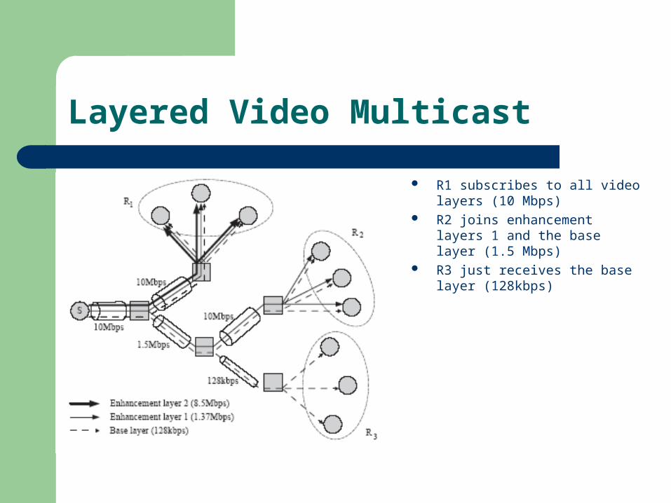
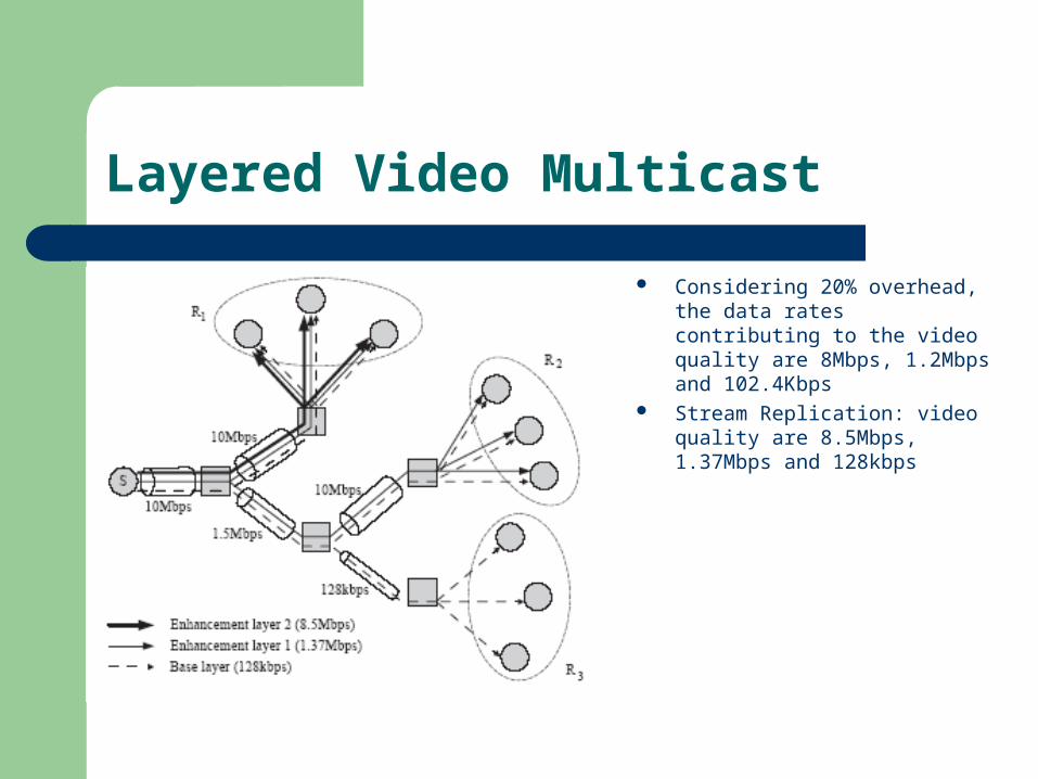
Layered Video Multicast
R1 subscribes to all video layers (10 Mbps)
R2 joins enhancement layers 1 and the base layer (1.5 Mbps)
R3 just receives the base layer (128kbps)

Layering or Replication?
Common wisdom states:– “Layering is better than replication”
However, it depends on– Layering bandwidth penalty– Specifics of encoding– Protocol complexity– Topological placement of receivers
Layered Video Multicast
Considering 20% overhead, the data rates contributing to the video quality are 8Mbps, 1.2Mbps and 102.4Kbps
Stream Replication: video quality are 8.5Mbps, 1.37Mbps and 128kbps

Bandwidth Penalty
Information theoretic results– Recent results showed that the performance of layered codi
ng is not better than that of non-layered coding– Increase the number of layers => significant quality degrada
tion
Packetization overhead– Enhancement layers carry:
Picture header GoP information Macroblock information

Experimental Comparison
Non-layered streams has better video quality
Difference in data rates ranges from 0.4% at 27.7dB PSNR to 117% at 23.2dB PSNR
For a good quality video, the overhead is around 20%

Providing a Fair Comparison
Need to insure that each scheme is optimal Two dimensions
– Stream assignment algorithm Determine the reception rate of each receiver by aggregating
the data rates of the assigned streams– Rate allocation algorithm
Determine the data rate of each stream Goal
– Maximize the bandwidth utilization by each scheme for a given network a particular set of receivers and given available bandwidth on the network links

System Model
Model the network by a graph G = (V, E)– V is a set of routers and hosts– E is a set of edges representing connection links
receivers ofnumber theisn
,...,1,| niVccC ii
Isolated rate– The reception rate of the receiver if there is no
constraint from other receivers in the same session

Stream Assignment
Cumulative layering– Define
i is the data rate of a stream and m is the number of layers
– Assign as many layers as possible Compute the isolated rates Assign that does not exceed the isolated rate
miRii ,...,1,|
i

Stream Assignment
Stream replication– Define
i is the data rate of a replicated stream and m is the number of replicated streams
Set of receivers assigned to stream i, – Two objectives
Minimum reception rate for all receivers is greater than zero Maximum
Greedy algorithm– Allocate 1 to all receivers to satisfy the minimum reception rate constraint
– Receiver is assigned a stream that has not been assigned and has the maximum value of group size and stream rate product
miRii ,...,1,|
ijj cc )(|
ji ii
m
i i bZje
subject to
1
Stream Assignment
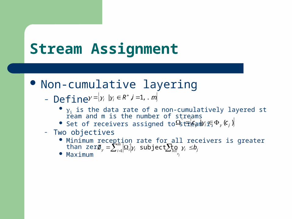
Non-cumulative layering– Define
i is the data rate of a non-cumulatively layered stream and m is the number of streams
Set of receivers assigned to stream i, – Two objectives
Minimum reception rate for all receivers is greater than zero Maximum
miRii ,...,1,|
)(|'jij cc
ji ii
m
i i bZje
subject to
1
'
Rate Allocation
Cumulative layering– Optimal receiver partitioning algorithm (Yang, Kim and Lam 2000)
determines the optimal rates of layer i, i Receivers are partitioned into K groups (G1, G2,…, GK) Objective is to maximize the sum of receiver utilities Dynamic programming algorithm is used to find an optimal partition For a given partition, an optimal group transmission rate can be
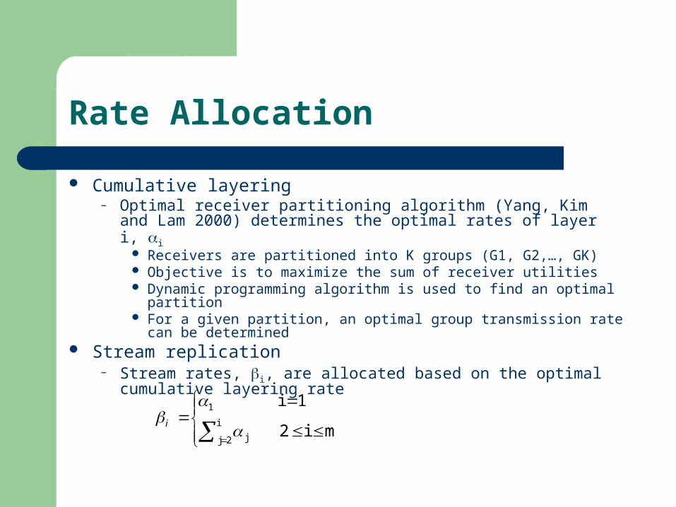
determined Stream replication
– Stream rates, i, are allocated based on the optimal cumulative layering rate
i
2j j
1
mi2
1i
i

Rate Allocation
Non-cumulative layering– Receiver can subscribe to any subset of layers
without joining the base layer ={1,2,4} => isolated rates of {1,2,3,4,5,6,7}– 2m-1 different link capacities with m non-
cumulative layers i are allocated based on i =>
43213
32121
212
11

Performance Metrics
Average reception rate– Average rate received by a receiver
Average effective reception rate– Amount of data received less the layering overhead
Total bandwidth usage– Adding the total traffic carried by all links in the network for
the multicast session
Efficiency– total effective reception rate / total bandwidth usage

Network Topology
Georgia Tech Internetwork Topology Models (GT-ITM)
– 1 server– 1640 nodes with 10 transit domains– 4 nodes per transit domains, 4 stubs per transit node, 10 no
des in a stub domain– transit-to-transit edges = 2.4Gbps – stub-to-stub edges = 10Mbps and 1.5Mbps – transit-to-stub edges = 155Mbps, 45Mbps and 1.5Mbps – number of layers = 8– amount of penalty = 20%
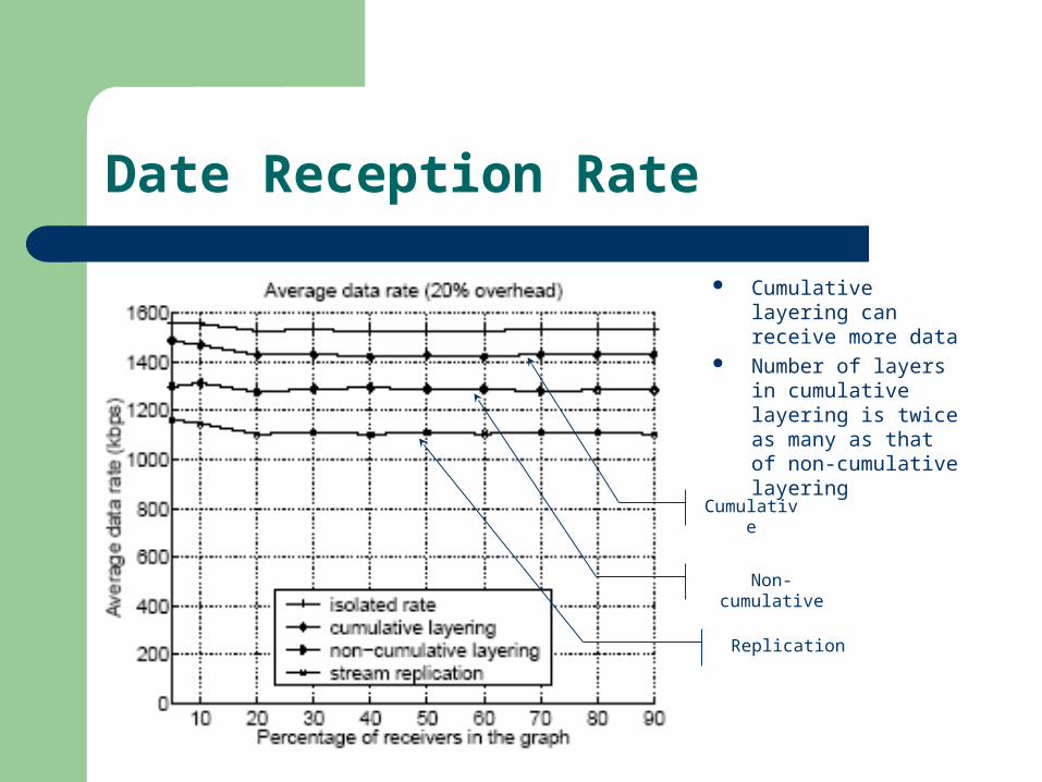
Date Reception Rate
Cumulative layering can receive more data
Number of layers in cumulative layering is twice as many as that of non-cumulative layering
Cumulative
Non-cumulative
Replication

Bandwidth Usage
Bandwidth consumption of cumulatively layered multicasting is the largest
Cumulative
Non-cumulative
Replication

Effective Reception Rate
Only 80% of data contributes to improving the video quality
Cumulative
Non-cumulative
Replication
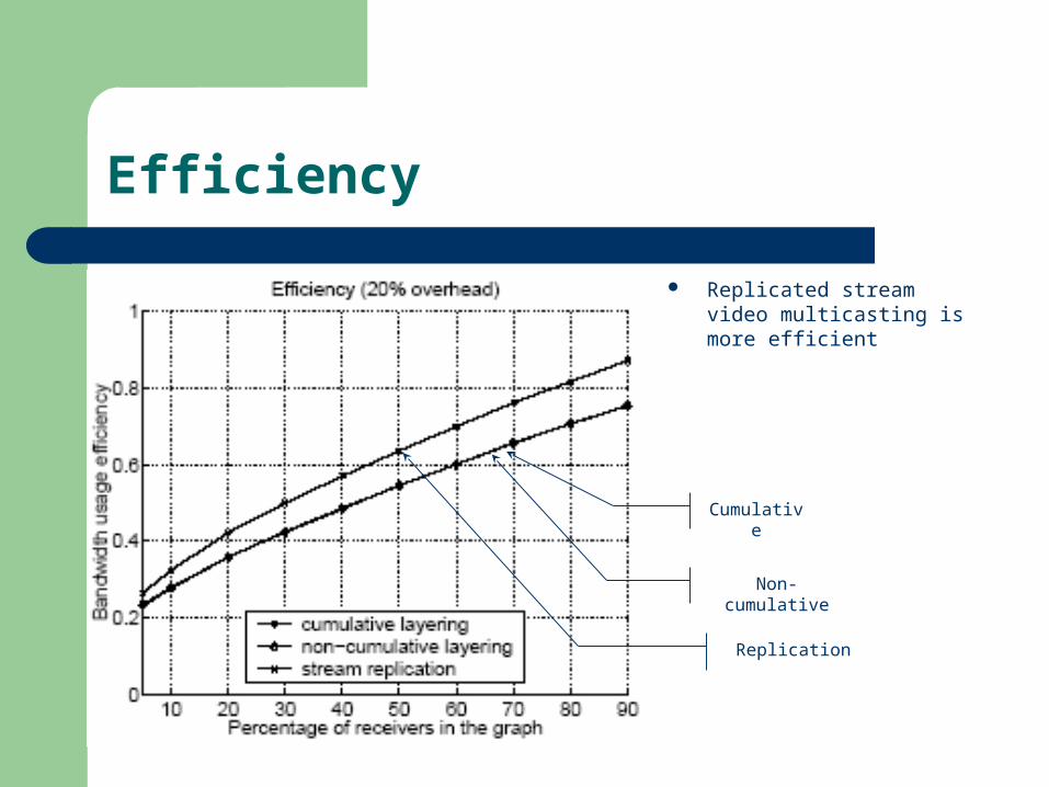
Efficiency
Replicated stream video multicasting is more efficient
Cumulative
Non-cumulative
Replication
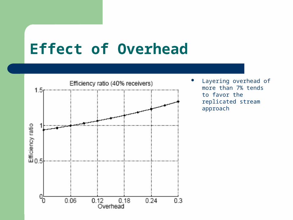
Effect of Overhead
Layering overhead of more than 7% tends to favor the replicated stream approach

Effect of the number of layers
Efficiency of stream replication is always greater than that of cumulative layering
The effect is not so significant

Narrow Distribution
Wide distribution Narrow distribution
The layering approach achieves better bandwidth efficiency when multiple streams share the bottleneck link
In narrow distribution, the reception rates in Figure (a) is larger than that of Figure (b) by 1.63Mbps
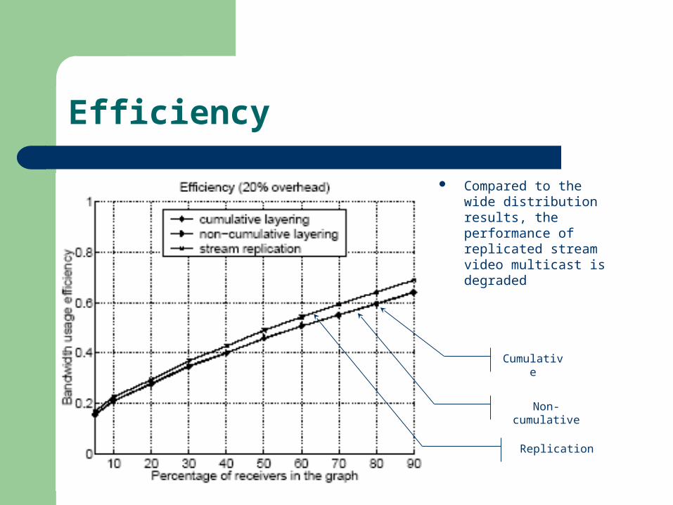
Efficiency
Compared to the wide distribution results, the performance of replicated stream video multicast is degraded
Cumulative
Non-cumulative
Replication

Protocol Complexity
Receiver-driven Layered Multicast (RLM) Receivers decide whether to drop additional layer or not Join experiment incur a bandwidth overhead Receivers send a join message and multicast a message
identifying the experimental layer to the group
Layered video multicasting– Receiver can join multiple groups– Large multicast group size
Replicated stream video multicasting– Receiver only join one group– Small multicast group size

Average Group Size
Group size in cumulatively layered video multicasting is twice as large as that in stream replication
More bandwidth to multicast a message reporting the “join” experiment

Conclusion
Identified the factors affecting relative merits of layering versus replication
– Layering penalty– Specifics of the encoding– Protocol complexity– Topological placement
Developed stream assignment and rate allocation algorithms
Investigated the conditions under which each scheme is superior