


Languages
Pages
Legal


H80SV12017 200W DC/DC Power Modules
Datasheet E-mail: [email protected]
DS_H80SV12017_01112018 http://www.deltaww.com/dcdc
P1
Delphi Series H80SV, half Brick Family
DC/DC Power Modules: 16.8~137.5 Vin,
54/48/24/15/12Vout,200W
The H80SV series Half-Brick is isolated 200W DC/DC converters with
4242VDC isolation. The H80SV family comes with a host of industry-
standard features, such as over current protection, over voltage protection,
over temperature protection and remote on/off. All models have an ultra-
wide 8:1 input voltage range (16.8V to 137.5V). With operating
temperature of -40°C to +85°C, it is suitable for customers’ critical
applications, such as process control and automation, transportation, data
communication and telecom equipment, test equipment, medical device
and wherever space on the PCB is critical.
FEATURES
Efficiency up to 90% @72Vin 12Vout
Ultra wide input range, 16.8V-137.5V
14.4V/1S, 200V/1S transient voltage
Package with Industry Standard Pinout
Package Dimension: 63.1mm*60.6mm*13mm (2.49’’*2.39’’*0.51’’)
OUTPUT OVP,OCP(hiccup) OTP(auto recovery)
Positive or Negative Remote ON/OFF
Without tantalum capacitor inside module
Operating Base Plate Temperature range - 40°C to +100°C
4242VDC input to output reinforced isolation
Unit operation monitor PIN option
A fixed frequency pulse PIN option
Hold up time PIN option
UVLO set up PIN option
RoHs Compliant
5 Years Product Warranty
Heat-sink is optional
Meet requirements of EN50155
UL60950-1, 2nd Edition certified
APPLICATIONS
Railway /Transportation system
SIMPLIFIED APPLICATION CIRCUIT
VIN(+)
BUS(+)
ON/OFF
PULSE OUT
VIN(-)
VOUT(+)
SENSE(+)
TRIM
SENSE(-)
VOUT (-)
UVLO
FUSE
EMI filterInputSource
**
**
* optional component
*
*
Datasheet E-mail: [email protected]
DS_H80SV12017_01112018 http://www.deltaww.com/dcdc
P2
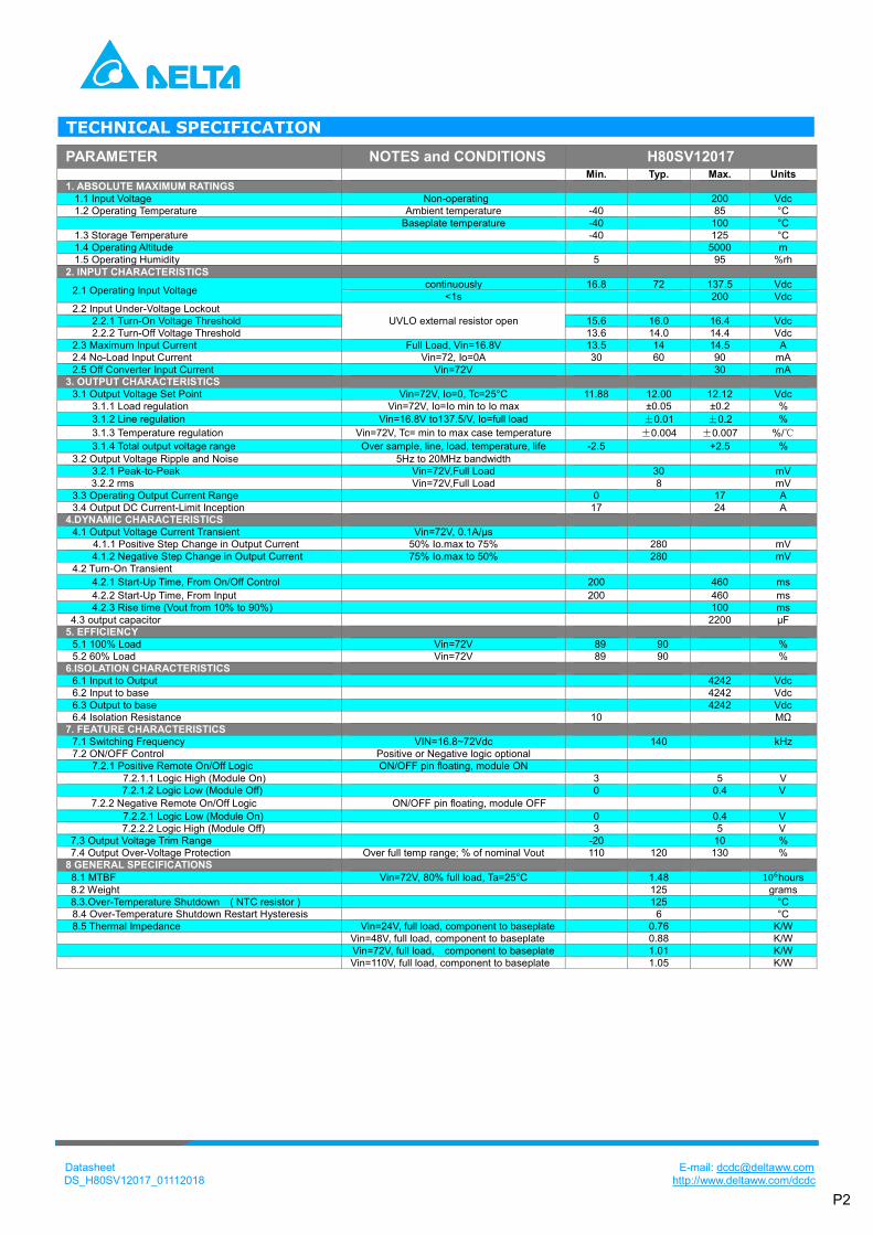
TECHNICAL SPECIFICATION
PARAMETER NOTES and CONDITIONS H80SV12017 Min. Typ. Max. Units
1. ABSOLUTE MAXIMUM RATINGS
1.1 Input Voltage Non-operating 200 Vdc
1.2 Operating Temperature Ambient temperature -40 85 °C
Baseplate temperature -40 100 °C
1.3 Storage Temperature -40 125 °C
1.4 Operating Altitude 5000 m
1.5 Operating Humidity 5 95 %rh
2. INPUT CHARACTERISTICS
2.1 Operating Input Voltage continuously 16.8 72 137.5 Vdc
<1s 200 Vdc
2.2 Input Under-Voltage Lockout
UVLO external resistor open
2.2.1 Turn-On Voltage Threshold 15.6 16.0 16.4 Vdc
2.2.2 Turn-Off Voltage Threshold 13.6 14.0 14.4 Vdc
2.3 Maximum Input Current Full Load, Vin=16.8V 13.5 14 14.5 A
2.4 No-Load Input Current Vin=72, Io=0A 30 60 90 mA
2.5 Off Converter Input Current Vin=72V 30 mA 3. OUTPUT CHARACTERISTICS
3.1 Output Voltage Set Point Vin=72V, Io=0, Tc=25°C 11.88 12.00 12.12 Vdc
3.1.1 Load regulation Vin=72V, Io=Io min to Io max ±0.05 ±0.2 %
3.1.2 Line regulation Vin=16.8V to137.5/V, Io=full load ±0.01 ±0.2 %
3.1.3 Temperature regulation Vin=72V, Tc= min to max case temperature ±0.004 ±0.007 %/℃
3.1.4 Total output voltage range Over sample, line, load, temperature, life -2.5 +2.5 %
3.2 Output Voltage Ripple and Noise 5Hz to 20MHz bandwidth
3.2.1 Peak-to-Peak Vin=72V,Full Load 30 mV
3.2.2 rms Vin=72V,Full Load 8 mV
3.3 Operating Output Current Range 0 17 A
3.4 Output DC Current-Limit Inception 17 24 A 4.DYNAMIC CHARACTERISTICS
4.1 Output Voltage Current Transient Vin=72V, 0.1A/µs
4.1.1 Positive Step Change in Output Current 50% Io.max to 75% 280 mV
4.1.2 Negative Step Change in Output Current 75% Io.max to 50% 280 mV
4.2 Turn-On Transient
4.2.1 Start-Up Time, From On/Off Control 200 460 ms
4.2.2 Start-Up Time, From Input 200 460 ms
4.2.3 Rise time (Vout from 10% to 90%) 100 ms
4.3 output capacitor 2200 µF 5. EFFICIENCY
5.1 100% Load Vin=72V 89 90 %
5.2 60% Load Vin=72V 89 90 % 6.ISOLATION CHARACTERISTICS
6.1 Input to Output 4242 Vdc
6.2 Input to base 4242 Vdc
6.3 Output to base 4242 Vdc
6.4 Isolation Resistance 10 MΩ 7. FEATURE CHARACTERISTICS
7.1 Switching Frequency VIN=16.8~72Vdc 140 kHz
7.2 ON/OFF Control Positive or Negative logic optional
7.2.1 Positive Remote On/Off Logic ON/OFF pin floating, module ON
7.2.1.1 Logic High (Module On) 3 5 V
7.2.1.2 Logic Low (Module Off) 0 0.4 V
7.2.2 Negative Remote On/Off Logic ON/OFF pin floating, module OFF
7.2.2.1 Logic Low (Module On) 0 0.4 V
7.2.2.2 Logic High (Module Off) 3 5 V
7.3 Output Voltage Trim Range -20 10 %
7.4 Output Over-Voltage Protection Over full temp range; % of nominal Vout 110 120 130 % 8 GENERAL SPECIFICATIONS
8.1 MTBF Vin=72V, 80% full load, Ta=25°C 1.48 106hours
8.2 Weight 125 grams
8.3.Over-Temperature Shutdown ( NTC resistor ) 125 °C
8.4 Over-Temperature Shutdown Restart Hysteresis 6 °C
8.5 Thermal Impedance Vin=24V, full load, component to baseplate 0.76 K/W
Vin=48V, full load, component to baseplate 0.88 K/W
Vin=72V, full load, component to baseplate 1.01 K/W
Vin=110V, full load, component to baseplate 1.05 K/W

Datasheet E-mail: [email protected]
DS_H80SV12017_01112018 http://www.deltaww.com/dcdc
P3
ELECTRICAL CHARACTERISTICS CURVES
Figure 1: Efficiency vs. load current at 25°C.
Figure 3: Turn-on transient at full load current (100ms/div).
Top Trace: Vout: 4V/div; Bottom Trace:Vin:50V/div
Figure 5: Output voltage response to step-change in load current (50%-75%-50% of full load; di/dt = 0.1A/µs).
Trace: Vout: 100mV/div; Time: 1ms/div
Figure 2: Efficiency vs. load current for input voltage at
25°C.
Figure 4: Turn-on transient at full load current (100ms/div).
Top Trace: Vout: 4V/div; Bottom Trace: ON/OFF:5V/div
Figure 6: Output voltage ripple at Vin=72V and full load
Trace: Vout: 20 mV/div, 2us/div; Bandwidth: 20 MHz.
70.00%72.00%74.00%76.00%78.00%80.00%82.00%84.00%86.00%88.00%90.00%92.00%94.00%96.00%
0 2 4 6 8 10 12 14 16 18
effi
cien
cy
output current(A)
24V
48V
72V
110V
0
5
10
15
20
25
30
0 2 4 6 8 10 12 14 16 18
Po
wer
loss
(w)
output current(A)
24V
48V
72V
110V
Datasheet E-mail: [email protected]
DS_H80SV12017_01112018 http://www.deltaww.com/dcdc
P4
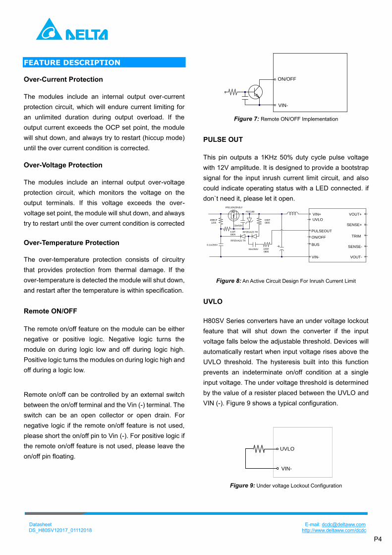
FEATURE DESCRIPTION Over-Current Protection
The modules include an internal output over-current
protection circuit, which will endure current limiting for
an unlimited duration during output overload. If the
output current exceeds the OCP set point, the module
will shut down, and always try to restart (hiccup mode)
until the over current condition is corrected.
Over-Voltage Protection
The modules include an internal output over-voltage
protection circuit, which monitors the voltage on the
output terminals. If this voltage exceeds the over-
voltage set point, the module will shut down, and always
try to restart until the over current condition is corrected
Over-Temperature Protection
The over-temperature protection consists of circuitry
that provides protection from thermal damage. If the
over-temperature is detected the module will shut down,
and restart after the temperature is within specification.
Remote ON/OFF
The remote on/off feature on the module can be either
negative or positive logic. Negative logic turns the
module on during logic low and off during logic high.
Positive logic turns the modules on during logic high and
off during a logic low.
Remote on/off can be controlled by an external switch
between the on/off terminal and the Vin (-) terminal. The
switch can be an open collector or open drain. For
negative logic if the remote on/off feature is not used,
please short the on/off pin to Vin (-). For positive logic if
the remote on/off feature is not used, please leave the
on/off pin floating.
ON/OFF
VIN-
Figure 7: Remote ON/OFF Implementation
PULSE OUT
This pin outputs a 1KHz 50% duty cycle pulse voltage
with 12V amplitude. It is designed to provide a bootstrap
signal for the input inrush current limit circuit, and also
could indicate operating status with a LED connected. if
don`t need it, please let it open.
RF05VA2S TR
PDZ18B
RF05VA2S TR
33n/250V
100/F
0805
100/F
0805
0.1U/250V
6.8/F
0805
33n/50V
IPB110N20N3LF
499K/F
1206
VIN+
UVLO
PULSEOUT
ON/OFF
BUS
VIN-
VOUT+
SENSE+
TRIM
SENSE-
VOUT-
Figure 8: An Active Circuit Design For Inrush Current Limit
UVLO
H80SV Series converters have an under voltage lockout
feature that will shut down the converter if the input
voltage falls below the adjustable threshold. Devices will
automatically restart when input voltage rises above the
UVLO threshold. The hysteresis built into this function
prevents an indeterminate on/off condition at a single
input voltage. The under voltage threshold is determined
by the value of a resister placed between the UVLO and
VIN (-). Figure 9 shows a typical configuration.
UVLO
VIN-
Figure 9: Under voltage Lockout Configuration
Datasheet E-mail: [email protected]
DS_H80SV12017_01112018 http://www.deltaww.com/dcdc
P5
The table below shows UVLO values for various nominal
input voltages and the required resistor.
Nominal Vin 24V 36V 48V 72V 96V 110V
Turn-off Threshold
12.0±0.4V 14.0±0.4V
21.2
±0.4V
28.4
±0.4V
42.8
±1V
57.2
±1V
65.6
±2V
Turn-on Threshold
14.0±0.4V 16.0±0.4V
24.5
±0.4V
33.6
±0.4V
50.4
±1V
67.6
±1V
76.8
±2V
UVLO External
Resistor (KΩ)*
2.2Meg
(UVLO to
Vin+)
open 24.9 12.4 6.19 4.12 3.48
Note: if need to configure UVLO turn off threshold to 12V,
please make sure the output power is no more than 120w,
even though the 12V operating is short duration.
Otherwise the input current maybe over spec and cause
some issue.
Hold up time
Hold up time is defined as the duration of time that the
DC/DC converter output will remain active following a loss
of input power. The BUS+ pin is for hold-up time function.
It is designed to work with an external circuit comprises
C4, R4, D1. When input power supply is interrupt, the H80
DCDC use the energy stored in C4 to support operation.
A typical configuration shows as Figure 10.
R4:100ohm,KNP100JT-73100R/YAGEO
D1:200V/3A,
If hold-up time function is not needed, just leave the 3
components open.
BUS
VIN-
R3
C3C4
R4
D1
Hold- up time circuit
Figure 10: Connection of External Hold-up Circuit
This function provides energy that maintains the DC-
DC converter in operation for 10mS of hold up time.
The capacity in the application is recommended as
below.
Vin
Capacitance
24V 36V 48V 72V 96V 110V
For 10 mS 2400uF 2400uF 2400uF 2400uF 820uF 560uF
For 30 mS 7200uF 7200uF 7200uF 7200uF 2460uF 1680uF
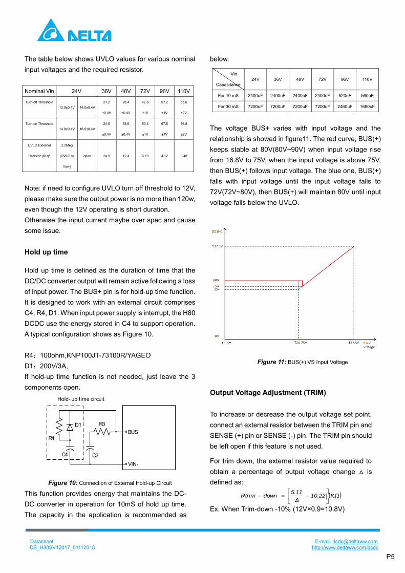
The voltage BUS+ varies with input voltage and the
relationship is showed in figure11. The red curve, BUS(+)
keeps stable at 80V(80V~90V) when input voltage rise
from 16.8V to 75V, when the input voltage is above 75V,
then BUS(+) follows input voltage. The blue one, BUS(+)
falls with input voltage until the input voltage falls to
72V(72V~80V), then BUS(+) will maintain 80V until input
voltage falls below the UVLO.
Figure 11: BUS(+) VS Input Voltage
Output Voltage Adjustment (TRIM)
To increase or decrease the output voltage set point,
connect an external resistor between the TRIM pin and
SENSE (+) pin or SENSE (-) pin. The TRIM pin should
be left open if this feature is not used.
For trim down, the external resistor value required to
obtain a percentage of output voltage change △ is
defined as:
KΩ10.22Δ
5.11downRtrim
Ex. When Trim-down -10% (12V×0.9=10.8V)

Datasheet E-mail: [email protected]
DS_H80SV12017_01112018 http://www.deltaww.com/dcdc
P6
KΩ40.88KΩ10.2210%
5.11downRtrim
For trim up, the external resistor value required to
obtain a percentage output voltage change △ is defined as:
KΩ40Δ
45upRtrim
Ex. When Trim-up +10% (12V×110%=13.2V)
KΩ4904010%
45upRtrim
DESIGN CONSIDERATIONS Input Source Impedance
C1:1UF MLCC or film cap, placed as close to module
as possible
C2:100UF ALCAP
L1:3.3uH inductor, depress the ripple current flow into
C2
For better EMC performance, it is recommended that C2
be parallel connected with MLCC 1UF like C3
VIN+
VIN-
C1
L1
C2 C3
Figure 12 input filter design
Bus Cap and Resistor
An electrolytic cap (C3) at least 200uF and a resistor
(R3) 3ohm connected between bus+ and Vin- is
necessary. The cap provides/absorb transient power
and make the DCDC operating stable. The series
resistor R3 is recommended to depress the high
frequency ripple current flow into C3.
R3
C3
BUS
VIN-
Figure 13 BUS pin circuit
Safety Considerations
The power module must be installed in compliance with
the spacing and separation requirements of the end-
user’s safety agency standard, i.e., UL 60950-1, 2nd
Edition, 2014-10-14, CSA C22.2 No. 60950-1-07, 2nd
Edition, 2014-10, IEC 60950-1: 2005 + A1: 2009 + A2:
2013 and EN 60950-1: 2006 + A11: 2009 + A1: 2010 +
A12: 2011 + A2: 2013, if the system in which the power
module is to be used must meet safety agency
requirements.
Reinforced insulation is provided between the input and
output of the module. Input is considered as secondary
hazardous voltage which main transient is up to 1500Vpk
and output is considered as SELV circuit. The input
source must be insulated from the ac mains by reinforced
or double insulation. The input terminals of the module
are not considered as operator accessible.
A SELV reliability test may require when install on the
system where the module is used, in combination with
the module, to ensure that under a single fault,
hazardous voltage does not appear at the module’s
output.
Soldering and Cleaning Considerations Post solder cleaning is usually the final board assembly
process before the board or system undergoes
electrical testing. Inadequate cleaning and/or drying
may lower the reliability of a power module and severely
affect the finished circuit board assembly test. Adequate
cleaning and/or drying is especially important for un-
encapsulated and/or open frame type power modules.
For assistance on appropriate soldering and cleaning
procedures, please contact Delta’s technical support
team.

Datasheet E-mail: [email protected]
DS_H80SV12017_01112018 http://www.deltaww.com/dcdc
P7
EMC CIRCUIT
C127
C125
C132
RV1
FL1
R110
R111
C124
C2
C4
C123
L1
C1
R3
C3
EARTHEARTH
VO+
VO-
VIN+
UVLO
PULSE OUT
ON/OFF
BUS
VIN-
IN+
IN-
OUT+
OUT-
Figure 14 input filter design for EN50155
ID PART NO. TYPE PARAMETERS QTY VENDOR
RV1 (MOV) B72207S0131K101 Varistor 170VDC,1.2KA 1 EPCOS
C123,C124,
C127,C132
R413F1100JU00M Capacitor,Y2/X1 1000p,300VAC 4 KEMET
C125 R46KF310045M1M Capacitor,X2 0.1uF,275VAC 1 KEMET
FL1 PH9455.105NL Common choke 1mH 1 Pulse
R110,R111 RV1206FR-07100K 1206 1/4W 100k ohm 2 YAGEO
C1 C1210X474K251TX MLCC 0.47uF/250V(2pcs parallel) 2 HOLY STONE
C4 C1210X474K251TX MLCC 0.47uF/250V(2pcs parallel) 2 HOLY STONE
C2 EKXG201ELL101ML20S Capacitor, Electrolytic 100uF,200V 1 NCC
C3 EKXJ251EC3121ML25S Capacitor, Electrolytic 120uF,250V(2pcs parallel) 2 NCC
R3 PNP100JT-52 3R RES WW 1W 3ohm J
FR SMALL
3.01 ohm/1W 1 YAGEO
L1 CMLS104T-3R3MS choke 3uH 1 Cyntec

Datasheet E-mail: [email protected]
DS_H80SV12017_01112018 http://www.deltaww.com/dcdc
P8
THERMAL CONSIDERATIONS
The thermal curve is based on the test setup shown as figure15. The module is mounted on an Al plate and was
cooled by cooling liquid.
Figure16 shows the location to monitor the temperature of the module’s baseplate. The baseplate temperature in
thermal curve is a reference for customer to make thermal evaluation and make sure the module is operated under
allowable temperature. (Thermal curves shown in Figure17 are based on different input voltage).
Figure 15: Test setup Figure 16: Temperature measured point
THERMAL CURVES
Figure 17: Output Power vs Baseplate temperature @Vin=16.8V~137.5V

Datasheet E-mail: [email protected]
DS_H80SV12017_01112018 http://www.deltaww.com/dcdc
P9
MECHANICAL DRAWING(BASEPLATE)
Figure 18: The pin function and mechanical drawing
Datasheet E-mail: [email protected]
DS_H80SV12017_01112018 http://www.deltaww.com/dcdc
P10
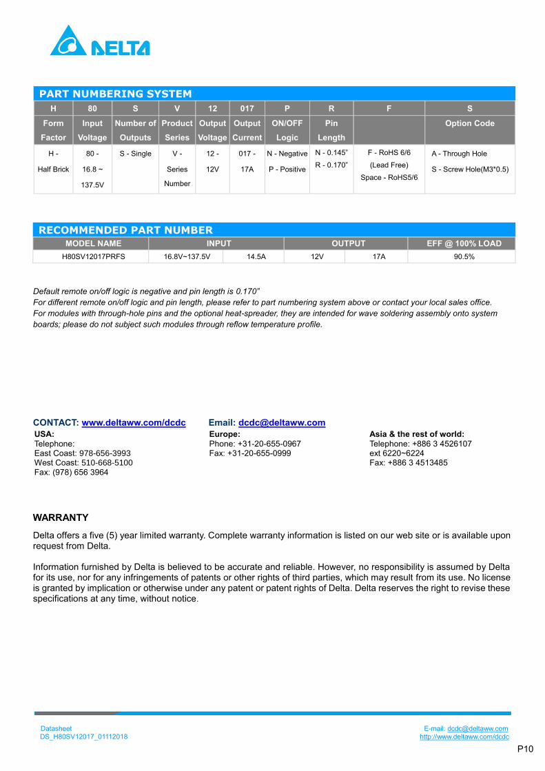
PART NUMBERING SYSTEM
H 80 S V 12 017 P R F S
Form
Factor
Input
Voltage
Number of
Outputs
Product
Series
Output
Voltage
Output
Current
ON/OFF
Logic
Pin
Length
Option Code
H -
Half Brick
80 -
16.8 ~
137.5V
S - Single V -
Series
Number
12 -
12V
017 -
17A
N - Negative
P - Positive
N - 0.145”
R - 0.170”
F - RoHS 6/6
(Lead Free)
Space - RoHS5/6
A - Through Hole
S - Screw Hole(M3*0.5)
RECOMMENDED PART NUMBER
MODEL NAME INPUT OUTPUT EFF @ 100% LOAD
H80SV12017PRFS 16.8V~137.5V 14.5A 12V 17A 90.5%
Default remote on/off logic is negative and pin length is 0.170”
For different remote on/off logic and pin length, please refer to part numbering system above or contact your local sales office.
For modules with through-hole pins and the optional heat-spreader, they are intended for wave soldering assembly onto system
boards; please do not subject such modules through reflow temperature profile.
CONTACT: www.deltaww.com/dcdc Email: [email protected]
USA:
Telephone: East Coast: 978-656-3993 West Coast: 510-668-5100 Fax: (978) 656 3964
Europe:
Phone: +31-20-655-0967 Fax: +31-20-655-0999
Asia & the rest of world:
Telephone: +886 3 4526107 ext 6220~6224 Fax: +886 3 4513485
WARRANTY
Delta offers a five (5) year limited warranty. Complete warranty information is listed on our web site or is available upon request from Delta. Information furnished by Delta is believed to be accurate and reliable. However, no responsibility is assumed by Delta for its use, nor for any infringements of patents or other rights of third parties, which may result from its use. No license is granted by implication or otherwise under any patent or patent rights of Delta. Delta reserves the right to revise these specifications at any time, without notice.
Top Related