


Languages
Pages
Legal


1
TWO PORT TWO PORT NETWORKSNETWORKS

2
SUB - TOPICSSUB - TOPICSZ – PARAMETERY – PARAMETERT (ABCD) – PARAMETERTERMINATED TWO PORT NETWORKS
3
OBJECTIVESOBJECTIVES• TO UNDERSTAND ABOUT TWO – PORT
NETWORKS AND ITS FUNTIONS.• TO UNDERSTAND THE DIFFERENT
BETWEEN Z – PARAMETER, Y – PARAMETER, T – PARAMETER AND TERMINATED TWO PORT NETWORKS.
• TO INVERTIGATE AND ANALYSIS THE BEHAVIOUR OF TWO – PORT NETWORKS.
4
TWO – PORT NETWORKSTWO – PORT NETWORKS• A pair of terminals through which a
current may enter or leave a network is known as a port.
• Two terminal devices or elements (such as resistors, capacitors, and inductors) results in one – port network.
• Most of the circuits we have dealt with so far are two – terminal or one – port circuits.
5
• A two – port network is an electrical network with two separate ports for input and output.
• It has two terminal pairs acting as access points. The current entering one terminal of a pair leaves the other terminal in the pair.

6
Linear network+V-
I
I
One – port network
Linear network+V1
-
I1
I1 I2
I2
+V2
-
Two – port network

7
• Two (2) reason why to study two port – network:Such networks are useful in
communication, control system, power systems and electronics.
Knowing the parameters of a two – port network enables us to treat it as a “black box” when embedded within a larger network.

8
• From the network, we can observe that there are 4 variables that is I1, I2, V1and V2, which two are independent.
• The various term that relate these voltages and currents are called parameters.
9
Z – PARAMETER Z – PARAMETER • Z – parameter also called as impedance
parameter and the units is ohm (Ω)• Impedance parameters is commonly used
in the synthesis of filters and also useful in the design and analysis of impedance matching networks and power distribution networks.
• The two – port network may be voltage – driven or current – driven.
10
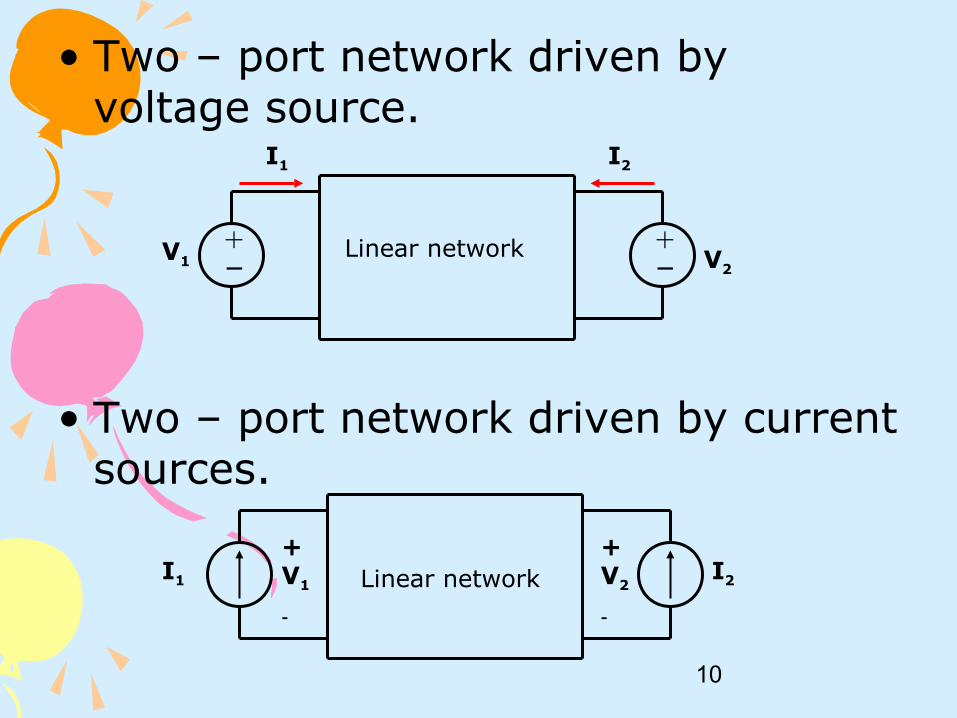
• Two – port network driven by voltage source.
• Two – port network driven by current sources.
Linear network
I1 I2
+−
+−V1 V2
I1 I2
+V1
-
Linear network+V2
-
11
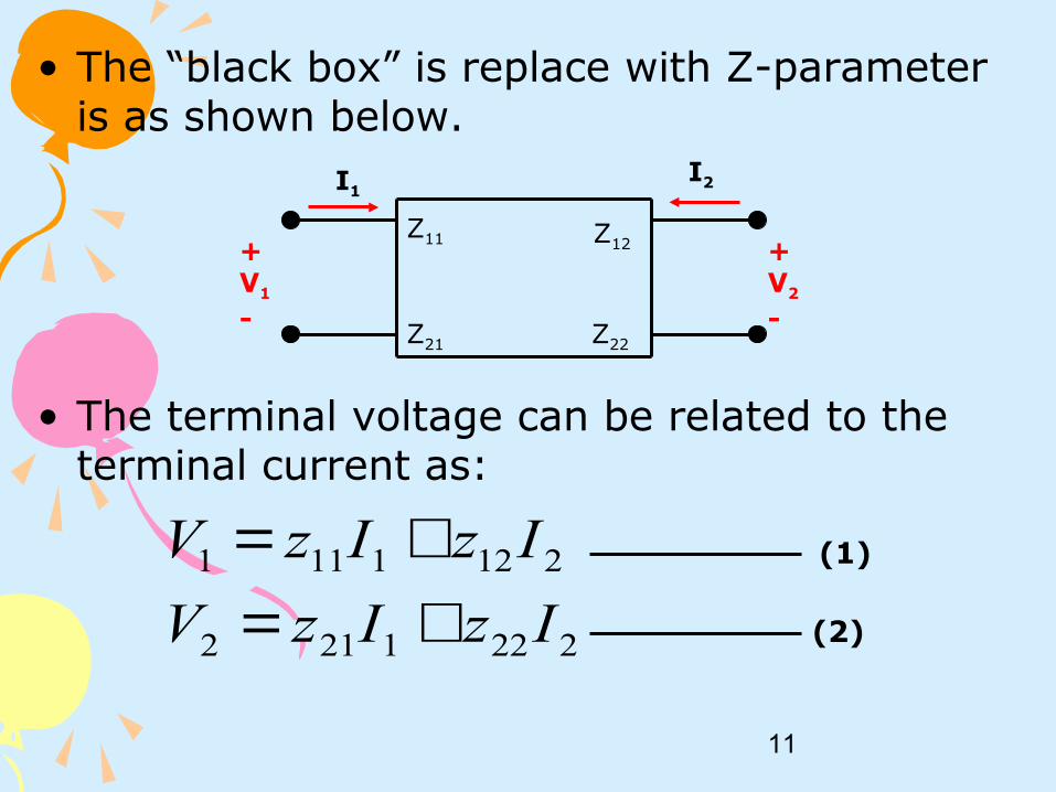
• The “black box” is replace with Z-parameter is as shown below.
• The terminal voltage can be related to the terminal current as:
+V1
-
I1I2
+V2
-
Z11
Z21
Z12
Z22
2221212
2121111
IzIzV
IzIzV
+=+= (1)
(2)

12
• In matrix form as:
• The Z-parameter that we want to determine are z11, z12, z21, z22.
• The value of the parameters can be evaluated by setting:1. I1= 0 (input port open – circuited)
2. I2= 0 (output port open – circuited)
=
2
1
2221
1211
2
1
I
I
zz
zz
V
V

13
• Thus,
01
221
01
111
2
2
=
=
=
=
I
I
I
Vz
I
Vz
02
222
02
112
1
1
=
=
=
=
I
I
I
Vz
I
Vz

14
• Where;z11 = open – circuit input impedance.
z12 = open – circuit transfer impedance from port 1 to port 2.
z21 = open – circuit transfer impedance from port 2 to port 1.
z22 = open – circuit output impedance.

15
Example 1Example 1Find the Z – parameter of the circuit below.
40Ω
240Ω120Ω
+
V1
_
+
V2
_
I1I2

16
Solution Solution
i) I2 = 0(open circuit port 2). Redraw the circuit.
40Ω
240Ω
120Ω
+
V1
_
+
V2
_
I1Ia
Ib

17
Ω==∴
→
=
=
84
(2) (1) sub
)2......(400
280
)1.......(120
1
111
1
1
I
VZ
II
IV
b
b
Ω==∴
→
=
=
72
(3) (4) sub
)4.......(400
120
.......(3)240
1
221
1
2
I
VZ
II
IV
a
a

18
ii) I1 = 0 (open circuit port 1). Redraw the circuit.
40Ω
240Ω120Ω
+
V1
_
+
V2
_
Iy I2
Ix
19
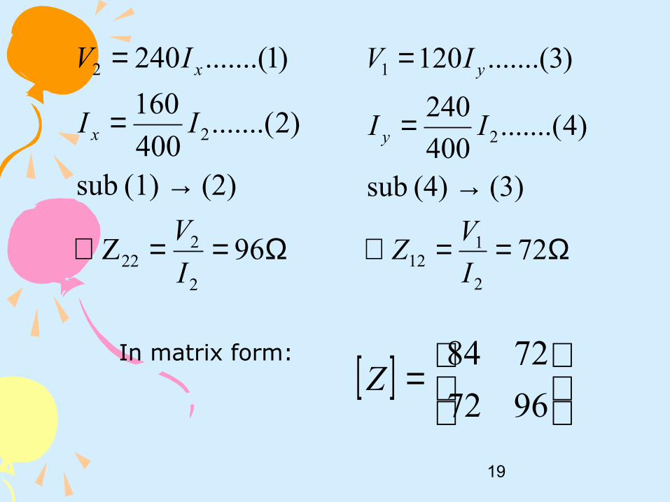
Ω==∴
→
=
=
96Z
(2)(1) sub
)2.......(400
160
)1.......(240
2
222
2
2
I
V
II
IV
x
x
Ω==∴
→
=
=
72
(3)(4) sub
)4.......(400
240
)3.......(120
2
112
2
1
I
VZ
II
IV
y
y
[ ]
=
9672
7284Z
In matrix form:

20
Example 2Example 2Find the Z – parameter of the circuit below
+
_
+
V1
_
+
V2
_-j20Ω
10Ωj4Ω2Ω
10I2
I2I1

21
Solution Solution i) I2 = 0 (open circuit port 2). Redraw the circuit.
Ω=∴=
Ω+==∴
+=
0 Z
circuit)(short 0 V
j4)(2 I
V Z
j4) (2 I V
21
2
1
111
11
+
V1
_
j4Ω2ΩI1
+
V2
_
I2 = 0

22
ii) I1 = 0 (open circuit port 1). Redraw the circuit.
Ω==∴
+=
+−
=
Ω==∴
=
j8)-(16 I
V Z
10
1
20
j V 2I
10
10I - V
j20
V I
10 I
V Z
10I V
2
222
22
2222
2
112
21
[ ]
+=
j8) - (1610
0j4)(2 Z
form;matrix In
+
_
+
V1
_
+
V2
_-j20Ω
10Ω
10I2
I2I1 = 0

23
Y - PARAMETERY - PARAMETER• Y – parameter also called admittance
parameter and the units is siemens (S).• The “black box” that we want to replace
with the Y-parameter is shown below.
+V1
-
I1I2
+V2
-
Y11
Y21
Y12
Y22

24
• The terminal current can be expressed in term of terminal voltage as:
• In matrix form:
2221212
2121111
VyVyI
VyVyI
+=+= (1)
(2)
=
2
1
2221
1211
2
1
V
V
yy
yy
I
I

25
• The y-parameter that we want to determine are Y11, Y12, Y21, Y22. The values of the parameters can be evaluate by setting:i) V1 = 0 (input port short – circuited).
ii) V2 = 0 (output port short – circuited).
• Thus;
01
221
01
111
2
2
=
=
=
=
V
V
V
IY
V
IY
02
222
02
112
1
1
=
=
=
=
V
V
V
IY
V
IY

26
Example 1Example 1
Find the Y – parameter of the circuit shownbelow.
5Ω
15Ω20Ω
+
V1
_
+
V2
_
I1I2

27
Solution Solution
i) V2 = 0
5Ω
20Ω
+
V1
_
I1
I2
Ia
SV
IY
II
IV
a
a
4
1
(2)(1) sub
)2.......(25
5
)1.......(20
1
111
1
1
==∴
→
=
=
SV
IY
IV
5
1
5
1
221
21
−==∴
−=

28
ii) V1 = 0
In matrix form;
5Ω
15Ω
+
V2
_
I1I2
Ix
SV
IY
II
IV
x
x
15
4
(4)(3) sub
)4.......(25
5
)3.......(15
2
222
2
2
==∴
→
=
=
SV
IY
IV
5
1
5
2
112
12
−==∴
−=
[ ] SY
−
−=
15
4
5
15
1
4
1

29
Example 2 (circuit with Example 2 (circuit with dependent source)dependent source)
Find the Y – parameters of the circuitshown.
+
_
+
V1
_
+
V2
_-j20Ω
10Ωj4Ω2Ω
10I2
I2I1

30
Solution Solution i) V2 = 0 (short – circuit port 2). Redraw the circuit.
+
_
+
V1
_
10Ωj4Ω2Ω
10I2
I2I1
S 0 V
I Y
S j0.2) - (0.1 j4 2
1
V
I Y
j4)I (2 V
0 I
1
221
1
111
11
==∴
=+
==∴
+==

31
ii) V1 = 0 (short – circuit port 1). Redraw the circuit.
)2.......(j20-
1
10
1 V 2I
10
10I - V
j20-
V I
)........(1j42
10I- I
22
2222
21
+=
+=
+=
+
_
+
V2
_-j20Ω
10Ωj4Ω2Ω
10I2
I2I1
[ ] S j0.025 0.050
j0.075 1.0j0.2 0.1 Y
form;matrix In
S j0.075) (-0.1 V
I Y
(1) (2) sub
S j0.025) (0.05 V
I Y
2
112
2
222
++−+
=∴
+==
→
+==∴

32
T (ABCD) PARAMETERT (ABCD) PARAMETER• T – parameter or ABCD – parameter is a
another set of parameters relates the variables at the input port to those at the output port.
• T – parameter also called transmission parameters because this parameter are useful in the analysis of transmission lines because they express sending – end variables (V1 and I1) in terms of the receiving – end variables (V2 and -I2).

33
• The “black box” that we want to replace with T – parameter is as shown below.
• The equation is:
+V1
-
I1I2
+V2
-
A11
C21
B12
D22
)2.......(
)1.......(
221
221
DICVI
BIAVV
−=−=

34
• In matrix form is:
• The T – parameter that we want determine are A, B, C and D where A and D are dimensionless, B is in ohm (Ω) and C is in siemens (S).
• The values can be evaluated by settingi) I2 = 0 (input port open – circuit)
ii) V2 = 0 (output port short circuit)
−
=
2
2
1
1
I
V
DC
BA
I
V

35
• Thus;
• In term of the transmission parameter, a network is reciprocal if;
02
1
02
1
2
2
=
=
=
=
I
I
V
IC
V
VA
02
1
02
1
2
2
=
=
=
=
V
V
I
ID
I
VB
1 BC - AD =

36
Example Example
Find the ABCD – parameter of the circuitshown below.
2Ω
10Ω
+
V2
_
I1 I2
+
V1
_
4Ω

37
Solution Solution i) I2 = 0,
2Ω
10Ω
+
V2
_
I1
+
V1
_
2.1
5
6
102
2
1.0
10
2
1
222
1
211
2
1
12
==∴
=+
=
+=
==∴
=
V
VA
VVV
V
VIV
SV
IC
IV

38
ii) V2 = 0,
( )
Ω=−=∴
+
−=
+=++=
=−=∴
−=
8.6
1010
1412
1012
102
4.1
14
10
2
1
221
211
2111
2
1
12
I
VB
IIV
IIV
IIIV
I
ID
II2Ω
10Ω
I1 I2
+
V1
_
4Ω
I1 + I2
[ ]
=
4.11.0
8.62.1T
39
TERMINATED TWO – PORT TERMINATED TWO – PORT NETWORKSNETWORKS
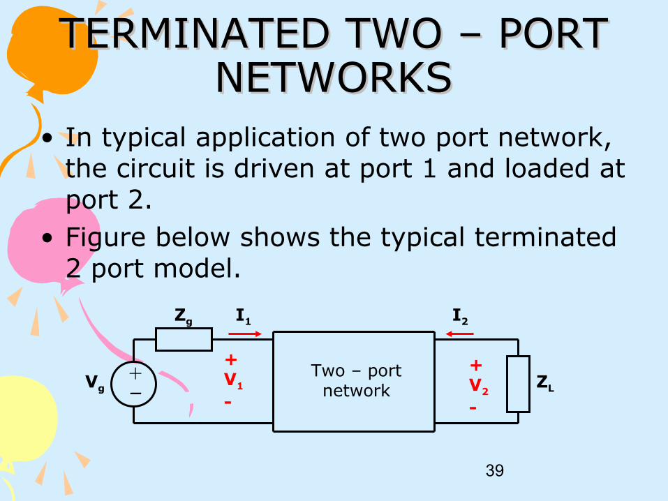
• In typical application of two port network, the circuit is driven at port 1 and loaded at port 2.
• Figure below shows the typical terminated 2 port model.
+V1
-
I1 I2
+V2
-
+−
Zg
ZLVg
Two – port network

40
• Zg represents the internal impedance of the source and Vg is the internal voltage of the source and ZL is the load impedance.
• There are a few characteristics of the terminated two-port network and some of them are;
gV
V
V
V
I
I
I
V
I
V
2g
1
2v
1
2i
2
2o
1
1i
A gain, voltageoverall v)
A gain, voltageiv)
A gain,current iii)
Zimpedance,output ii)
Zimpedance,input i)
=
=
=
=
=

41
• The derivation of any one of the desired expression involves the algebraic manipulation of the two – port equation. The equation are:1) the two-port parameter equation either Z or Y or ABCD.
For example, Z-parameter,
)2.......(IZIZV
)1.......(IZIV
2221212
2121111
+=+= Z
42
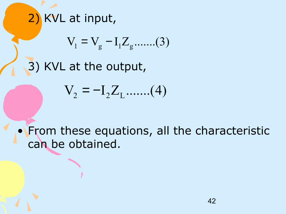
2) KVL at input,
3) KVL at the output,
• From these equations, all the characteristic can be obtained.
.......(3)ZIVV g1g1 −=
)4.......(ZIV L22 −=

43
Example 1 Example 1 For the two-port shown below, obtain the suitable value of Rs such that maximum power is available at the input terminal. The Z-parameter of the two-port network is given as
With Rs = 5Ω,what would be the value of
=
44
26
2221
1211
ZZ
ZZ
s
2
V
V
+V1
-
I1 I2
+V2
-
+−
Rs
4ΩVs
Z

44
Solution Solution 1) Z-parameter equation becomes;
2) KVL at the output;
Subs. (3) into (2)
)2.......(44
)1.......(26
212
211
IIV
IIV
+=+=
)3.......(4 22 IV −=
)4.......(21
2
II −=

45
Subs. (4) into (1)
For the circuit to have maximum power,
)5.......(5 11 IV =
Ω==∴ 51
11 I
VZ
Ω== 51ZRs

46
To find at max. power transfer, voltagedrop at Z1 is half of Vs
From equations (3), (4), (5) & (6)Overall voltage gain,
s
2
V
V
)6.......(21sVV =
5
12 ==s
g V
VA

47
Example 2Example 2The ABCD parameter of two – port network shown below are.
The output port is connected to a variable load for a maximum power transfer. Find RL and the maximum power transferred.
Ω20.1S
204

48
ABCD parameter equation becomesV1 = 4V2 – 20I2
I1 = 0.1V2 – 2I2
At the input port, V1 = -10I
(1)
(2)
(3)
Solution

49
(3) Into (1)-10I1 = 4V2 – 20I2
I1 = -0.4V2 2I2
(2) = (4)0.1V2 – 2I2 = -0.4V2 + 2I2
0.5V2 = 4I2
From (5);ZTH = V2/I2 = 8Ω
(4)
(5)
(6)
50
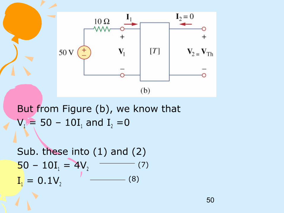
But from Figure (b), we know that V1 = 50 – 10I1 and I2 =0
Sub. these into (1) and (2)50 – 10I1 = 4V2
I1 = 0.1V2
(8)
(7)

51
Sub (8) into (7)V2 = 10
Thus, VTH = V2 = 10V
RL for maximum power transfer,RL = ZTH = 8Ω
The maximum power P = I2RL = (VTH/2RL)2 x RL = V2
TH/4RL = 3.125W
Top Related