


Languages
Pages
Legal


Construction Technology B (CON4313)
1/26
2 - Foundation The British Standard Code of Practice BS8004 defines a foundation as 'that part of
the structure designed and constructed to be in direct contact with and transmitting
loads to the ground'
1 Shallow Foundation (quick revision) 1.1 Pad footing
1.2 Strip footing
1.3 Raft footing
Solid Slab Raft
Beam and Slab Raft
Cellular Raft
1.4 Combined footing 2. Piled Foundation 2.1 Classification of Piles 2.1.1 Classification by Method of Load Transmission
End bearing piles
Friction piles
2.1.2 Classification by Method of Installation
Displacement Piles
Replacement Piles -

Construction Technology B (CON4313)
2/26
3. Displacement Piles Displacement piles are preformed piles made in a factory, transported to the site, and
then driven into the ground. They are also called ‘preformed piles’ or ‘driven piles’.
Preformed piles may be made of reinforced concrete or steel.
(There was a pile type called ‘driven cast-in-situ pile’. It was formed by driving a
shell or a casing with a closed end into the ground and then casting the annular space
with concrete. This type of pile is now obsolete)
3.1. Piling equipment for displacement piles Displacement piles are generally driven into the ground by one of the following
methods:
1. Percussion
2. Vibration
3.1.1 Percussive driving Piles are driven into the ground by the impact of heavy pile hammers. There are
several types of pile hammers:
a. Drop hammer (Fig. 2.1)
b. Diesel hammer (Fig. 2.2)
(These two types of piles are now obsolete.)
c. Hydraulic Hammer A hydraulic hammer unit is mounted on the pile while operating. It is similar to a
drop hammer but the weight is raised by hydraulic jacks. The weight then falls freely
under gravity on to the pile head. Hydraulic jacks are so powerful that the weight can
be up to 18 tonnes. The stroke height is about 1-2 m. The blow rate depends on the
stroke height and ranges from 40 to 100 blows per minutes.

Construction Technology B (CON4313)
3/26
Most hydraulic hammers are equipped with silencers nowadays. They produce less
noise than diesel hammers and they do not emit exhaust fumes. They are suitable for
hard drive.
3.1.2 Vibratory driving – vibration hammer (Fig. 2.3) Vibration hammer is comparatively silent. It is used in driving small displacement
piles such as H-piles and sheet piles. The equipment consists of a vibrating unit
mounted on the pile head transmitting vibrations down the length of the pile shaft.
These vibrations are in turn transmitted to the surrounding soil, reducing its shear
strength enabling the pile to sink into the subsoil under its own weight and also that
of the vibration hammer.
3.1.3 Piling rigs A piling rig has the function of guiding the pile at its correct alignment from the stage
of first pitching in position to its final penetration. It also carries the hammer and
maintains it in position co-axially with the pile. (Fig. 2.4)
3.1.4 Helmets The head of displacement piles must be protected from damage during driving. The
protection consists of resilient packing which is held in position by a steel helmet.
The resilient packing distributes the impact load from the piling hammer evenly on to
the pile head. (Fig. 2.5)
The helmet should fit loosely around the pile, so that the pile may rotate slightly
without inducing torsion on the pile.

Construction Technology B (CON4313)
4/26
3.2 Precast prestressed concrete tubular pile In the past, most of precast concrete piles were square in cross sections. They can be
made of either of normal reinforced concrete or prestressed concrete. Their bearing
capacity ranged between 800-1500 KN.
In 1980s, precast concrete piles in H.K. became tubular because of the development
of a manufacturing technology. This type of pile is prestressed and the concrete is
compacted by centrifugal spinning process. The spinning process effectively
compacts the zero slump concrete and produces a hollow tube without the need of a
former. They are then steam cured in an autoclave under high steam pressure and
high temperature in order to obtain a minimum concrete compressive strength of
about 80 MPa within three days.
The outside diameters of the piles are about 400-600 mm and in lengths of up to 12
m. They have a nominal bearing capacity in the range up to 3500 KN. (Fig. 2.6)
Each pile length has integral steel joint plates (end plates) cast onto ends of the pile.
Lengthening is done by a full penetration butt welding of the end plates.
The disadvantages of these piles are that they produce great noise and vibration
during the installation of these piles. Moreover, most Hong Kong soils are coarse,
containing boulders and rocks which are not too suitable for large diameter
displacement piles.
3.3 Preformed Steel piles 3.3.1 Hollow steel piles Two main types of hollow steel piles: tubular and box sections. Box piles are
normally driven with closed ends (now obsolete) with internal drop hammers. Open
ended tubes can be driven with vibration hammers. Hollow Steel piles have a high
resistance to lateral loading and buckling and good energy-absorbing properties.

Construction Technology B (CON4313)
5/26
They are particular suitable for structures subjected to lateral and impact loading such
as jetties and dolphins.
3.3.2 Steel H-pile Steel H-pile is strong and tough. The displacement of the soil is little compared with
other types of displacement piles. It is widely used in HK.
Driving steel piles generally do not require pile shoes. In hard conditions, the toe of
the pile may be strengthened. Strengthening may be carried out by welding steel
plates or angles to the toe of the pile (Fig. 2.7). Preformed pile shoes for H-piles are
also available (Fig. 2.8). In ground conditions where boulders exist, Oslo point may
be used (Fig. 2.9).
3.3.3 Lengthening Lengthening of steel H-pile is done by butt-welding. Splicers may be used to help
splicing.
3.3.4 Corrosion Protection Steel preformed piles may deteriorate as a result rusting. Corrosion protection is of
particular importance for steel piles because they are embedded in the ground and
become inaccessible for maintenance. A protective coating shall be applied on the
steel piles before being driven into the ground.
The surfaces of steel piles to which protective coatings will be applied shall be
prepared by blast cleaning.
(Source: General Specification for Civil Engineering Works)
Construction Technology B (CON4313)
6/26
3.4 Procedure of driving a displacement pile 1. Prepare a piling rig and a piling hammer.
2. Put marks on the pile length at 500 mm interval to indicate the length being
driven.
3. Pitch the pile in the piling rig. Check its alignment and verticality.
4. Place a suitable pile helmet on the pile head. Mount the piling hammer on top of
it and then start driving.
5. If the whole length of the pile has been driven into the ground, splice a new
length on it, then continue the driving.
6. Repeat step 5 until it renders significant resistance against driving.
7. Perform the set measurement. If the predetermined set is attained, the piling
process is completed. Otherwise repeat from step 5 until it does.
3.5 Measurement of set
‘Set’ related to the ultimate bearing capacity of the pile can be determined by pile
driving formulae by considering the parameters of the pile, the soil and the ground
condition. There are many pile driving formulae, among which the Hiley formula is
the most commonly used one.
The final set shall be measured as:
1. penetration per 10 blows, or
2. the number of blows required to produce 25 mm penetration.

Construction Technology B (CON4313)
7/26
3.6 Advantages and disadvantages of displacement piles 3.6.1 Advantages 1. Where large numbers of piles are to be installed in easy driving conditions, it
can be more economic.
2. Projection above ground level advantageous to marine structures.
3. The pile can be inspected for quality and soundness before driving.
4. Construction operations not affected by ground water.
5. Not liable to ‘squeezing’ or ‘necking’.
3.6.2 Disadvantages of displacement piles 1. Transporting the complete length of pile through narrow and/or congested
streets may be difficult.
2. The driving process, which is generally percussion, can cause unacceptable
noise and vibrations.
3. Pile driving hour is limited by environmental regulations.
4. May break during driving, causing delays and replacement charges.
5. Displacement of soil during driving may damage adjacent structure or cause up
lifting of adjacent piles.
6. Cannot be driven in very large diameters.
7. Cannot be driven in conditions of low headroom.

Construction Technology B (CON4313)
8/26
4. Replacement Pile Replacement pile is also called 'non-displacement pile'. It is formed by boring a pile
shaft and replacing the soil with in situ concrete. In Hong Kong, it is commonly
called ‘bored pile’.
4.1 Methods and equipment for boring pile shafts 4.1.1. Rotary boring Rotary boring involves a drilling rig which may be mounted on a mobile crane or a
truck. The drilling rig consists of a telescopic or extendable kelly bar on which a
boring tool is attached.
There are various types of boring tools: 1. Cheshire auger – The auger has only a few helix turns. It has to go up and down
repeatly to cut the soil and bring the spoil to the ground surface.
2. Continuous auger (flight auger) – It has a long helix. The spoil is continuously
brought to the ground surface by the spiral motion. However, the drilling rig
must provide sufficient torque to overcome the great friction (Fig. 2.10).
3. Drilling bucket – It is designed to withstand the high torque forces developed
during penetration of dense strata. The spoil is temporarily stored in the bucket to
reduce the friction created. The frequency of up and down motions can also be
reduced as compared with that of the Cheshire auger.
4. Coring bucket – It is used to raise a solid core of rock.
5. Chisel - It is used break through boulder or rock. (Fig. 2.11)

Construction Technology B (CON4313)
9/26
4.1.2 Grab boring A grab consists of a clamshell bucket which is operated by means of wire ropes and
suspended from a mobile crane. The grab is dropped on to the soil in an open
position and is then closed. It is then raised to the surface and emptied spoil at the
side of the borehole.
Virtually the rope can be of infinite length. The depth of a borehole can be over a
hundred meters by grab boring. Most boreholes are circular in cross section but can
be rectangular by using a rectangular grab (Fig. 2.12).
When boulders are encountered, they can be broken by free falling a chisel on to it.
The rock fragments are then removed by the grab. Chisel and grab are often used
alternatively to break through obstructions.

Construction Technology B (CON4313)
10/26
4.1.3 Down the hole (DTH) drilling A down the hole drill (DTH) is a large size hammer drill. It is equipped with a button
bit that can drill holes into rock with diameters up to 750 mm and to depths of several
hundred meters.
A conventional hammer drill becomes less efficient as the length of borehole
increases because of the loss of energy in drill stem. To overcome these difficulties
the ‘down the hole’ drill was developed. Its rotary motor remains above ground level
while the pneumatic hammer is followed down the hole. The drill stem rotates in
slow motion while the drill bit strikes rapidly. The drill debris is blown out by
compressed air. (Fig. 2.13)
4.1.4 Reverse circulation drilling (RCD) A reverse circulation drilling rig can drill at a fast rate in a wide range of ground
conditions including rocks. In Hong Kong, it is commonly use to drill the bed rock
sockets for bored piles. When boring in rock, rock roller bits are used.
The Reverse circulation drill sits on the temporary steel casing while operating. It
consists of a double wall drilling pipe and operates on the principle of air lifting.
Compressed air is injected through the annular space of the drilling pipe and
discharge near the base. The rising column of air and water at the centre of the
drilling pipe lifts the soil or rock fragments which has been loosened by the drilling
bit.
(Air lifting is also commonly used to clean the bottom of a bored pile before
concreting.) (Fig. 2.14)
Construction Technology B (CON4313)
11/26
4.1.6 Under-reaming The base of a bored pile can be enlarged to three times the shaft diameter to increase
the bearing capacity of the pile. The method is known as under-reaming which is
done by a belling bucket.
The belling bucket is lowered to the bottom a borehole by a kelly bar with the cutter
in retracted position. It is then rotated by the kelly bar and the cutter is jacked out to
form the bell. (Fig. 2.15, 2.16)

Construction Technology B (CON4313)
12/26
4.2 Methods of supporting boreholes 4.2.1 Self-supported (unsupported) For small diameter bored piles and in stable soils, the borehole may remain
unsupported without collapsing. However, a borehole without support is not
recommended in Hong Kong.
4.2.2 Supported with temporary casing (Fig. 2.17) In unstable or water-bearing ground, the bored pile shaft should be supported by a
steel casing to prevent collapse. The casing can be driven into the ground by a casing
oscillator (or a vibration hammer).
The oscillator consists of a collar clamp and a pair of hydraulic jacks. The collar
clamp grips the casing. The two hydraulic jacks extend and retract repeatly in
opposite phrases. This oscillation motion helps to cut the soil by the casing shoe and
sink the casing into to ground.
The steel casing is usually thick and expensive and will be retrieved after the
borehole is concreted. The casing oscillators (or vibrator hammer) the can be used to
withdraw the casing. In a long pile the casing may be stuck by the concrete and the
extraction becomes difficult. Moreover, temporary steel casings which are in contact
with concrete shall be withdrawn before the initial set of the concrete has taken place.
Otherwise, it shall be left in place.
To overcome this problem, it is advisable to extract the casing in stages, i.e., the
casing is extracted as concreting progresses upwards. However, it is important that a
sufficient concrete pressure head shall be maintained within the steel casing to ensure
that the pressure from external soil and ground water would not cause necking of the
pile.

Construction Technology B (CON4313)
13/26
4.2.3 Permanent casing Sometimes a permanent casing will be lowered into a temporary cased borehole. The
permanent casing is made of light gauge corrugated steel sheet. It is much cheaper
than the thick temporary casing.
The permanent casing prevents the expensive temporary casing being stuck by the
fresh concrete. It also reduces the risk of necking of the pile after extraction of the
temporary casing and prevents the fresh concrete being contaminated by soil and
ground water. Corrugated steel casings are often used in long piles and in difficult
grounds such as reclaimed land.
4.2.4 Supported with bentonite slurry (Fig. 2.18) Bentonite is a kind of clay. When mixed with the correct amount of water bentonite
slurry produces thixotropic properties, it gives a liquid behaviour when agitated and a
gel structure when undisturbed.
During boring, the borehole is filled with bentonite slurry. The boring action stirs the
slurry so it remains liquid state. But the slurry penetrates slightly into the subsoil and
forms a soft gel or so called 'filter cake' at the interface of the excavation sides.
Hydrostatic pressure caused by the slurry thrusting on the 'filter cake' that prevents
the borehole from collapse. This method is not suitable for soil with high
permeability.
4.3 Examples of Replacement Piles 4.3.1 Bored pile Bored pile is perhaps the most popular type of pile in Hong Kong currently. The
maximum diameter can be over 3 m and the pile length can be over 100 m. It can be
designed to carry loads up to 30000 kN.
Construction Technology B (CON4313)
14/26
There are various techniques for boring pile shafts and supporting them. The choices
of the methods and their combinations depend on the ground condition and the pile
design. Some typical examples are as follows:
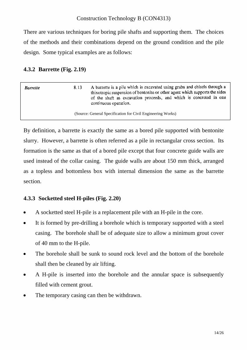
4.3.2 Barrette (Fig. 2.19) By definition, a barrette is exactly the same as a bored pile supported with bentonite
slurry. However, a barrette is often referred as a pile in rectangular cross section. Its
formation is the same as that of a bored pile except that four concrete guide walls are
used instead of the collar casing. The guide walls are about 150 mm thick, arranged
as a topless and bottomless box with internal dimension the same as the barrette
section.
4.3.3 Socketted steel H-piles (Fig. 2.20) A socketted steel H-pile is a replacement pile with an H-pile in the core.
It is formed by pre-drilling a borehole which is temporary supported with a steel
casing. The borehole shall be of adequate size to allow a minimum grout cover
of 40 mm to the H-pile.
The borehole shall be sunk to sound rock level and the bottom of the borehole
shall then be cleaned by air lifting.
A H-pile is inserted into the borehole and the annular space is subsequently
filled with cement grout.
The temporary casing can then be withdrawn.
(Source: General Specification for Civil Engineering Works)
Construction Technology B (CON4313)
15/26
4.3.4 Minipile (Micropile) Minipiles are defined as piles having a diameter of less than 300 mm. Generally they
range in shaft diameter from 50 to 250 mm, with working loads in the range of 50 to
500 kN. There are many ways of forming minipiles. A typical method currently used
in Hong Kong is (Fig. 2.21):
1. Drill a borehole of about 150 mm diameter with a rotary drilling rig and line the
borehole with a steel casing.
2. Grout the borehole with cement slurry from the bottom of the hole.
3. Insert the pile reinforcement into the casing. Normally it consists of 2-4 numbers
of T40 or T50 bars.
(The steel casing is left in place to enhance corrosion protection.)
The principal use of minipiles is for underpinning work or in steep slope where large
piling machine cannot access.
4.3.5 Installation procedure of Bored Piles i) Bored pile supported with temporary and permanent casing Procedure 1. Pitch a temporary steel casing in the correct position and drive it into the ground
with a casing oscillator.
2. Bore within the casing with a hammer grab. Boring shall not go beyond the
bottom of the casing to prevent collapse of the borehole.
3. If rocks or boulders are encountered, use a chisel to break them and then use the
grab to remove the fragments.
4. Extend the steel casing and drive it into the ground if necessary.
5. Repeat steps 2 to 4 until the founding rock is reached.
Construction Technology B (CON4313)
16/26
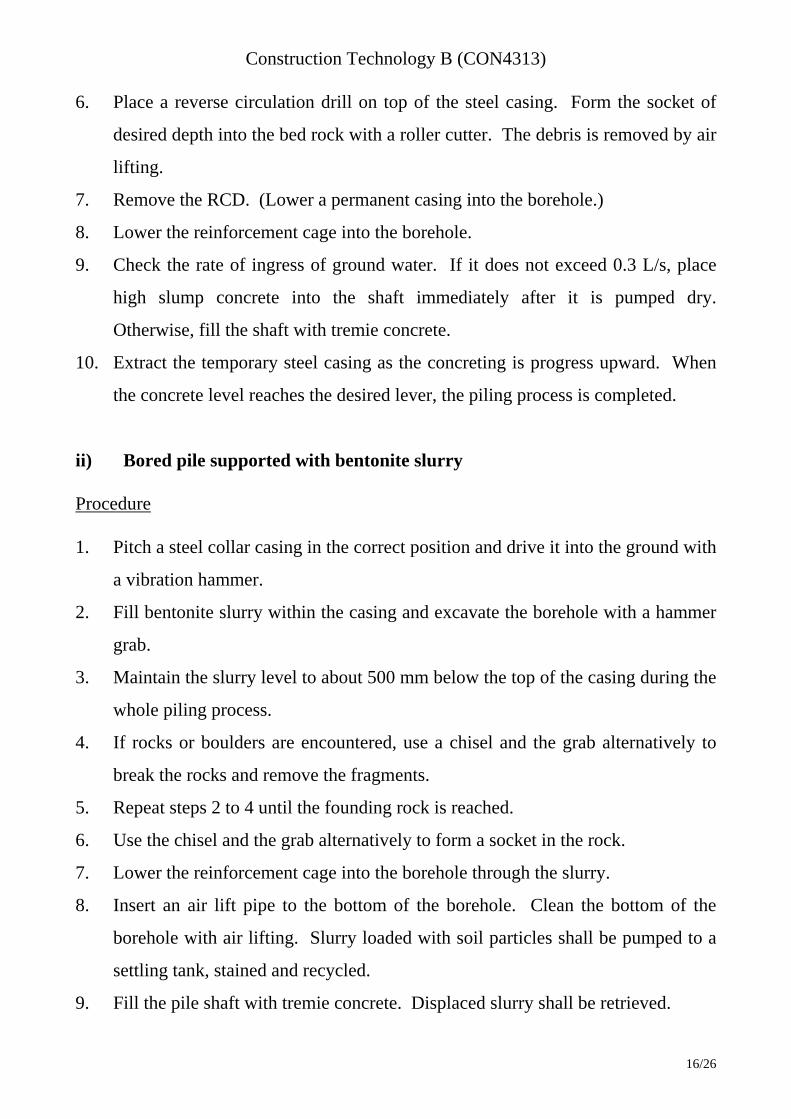
6. Place a reverse circulation drill on top of the steel casing. Form the socket of
desired depth into the bed rock with a roller cutter. The debris is removed by air
lifting.
7. Remove the RCD. (Lower a permanent casing into the borehole.)
8. Lower the reinforcement cage into the borehole.
9. Check the rate of ingress of ground water. If it does not exceed 0.3 L/s, place
high slump concrete into the shaft immediately after it is pumped dry.
Otherwise, fill the shaft with tremie concrete.
10. Extract the temporary steel casing as the concreting is progress upward. When
the concrete level reaches the desired lever, the piling process is completed.
ii) Bored pile supported with bentonite slurry Procedure 1. Pitch a steel collar casing in the correct position and drive it into the ground with
a vibration hammer.
2. Fill bentonite slurry within the casing and excavate the borehole with a hammer
grab.
3. Maintain the slurry level to about 500 mm below the top of the casing during the
whole piling process.
4. If rocks or boulders are encountered, use a chisel and the grab alternatively to
break the rocks and remove the fragments.
5. Repeat steps 2 to 4 until the founding rock is reached.
6. Use the chisel and the grab alternatively to form a socket in the rock.
7. Lower the reinforcement cage into the borehole through the slurry.
8. Insert an air lift pipe to the bottom of the borehole. Clean the bottom of the
borehole with air lifting. Slurry loaded with soil particles shall be pumped to a
settling tank, stained and recycled.
9. Fill the pile shaft with tremie concrete. Displaced slurry shall be retrieved.

Construction Technology B (CON4313)
17/26
10. Stop concreting with the concrete reaches 1 m about the cut-off level. Remove
the collar casing and the piling is completed.

Construction Technology B (CON4313)
18/26
4.4 Advantages and Disadvantages of Replacement Piles 4.4.1 Advantages of replacement piles: 1. Soil or rock removed in boring can be inspected for comparison with site
investigation data.
2. Can be installed in very large diameters.
3. Can be installed in very long length.
4. End enlargements up to three diameters are possible
5. Can be installed without appreciable noise or vibration.
6. Can be installed in conditions of very low headroom.
7. No risk of ground heave.
4.4.2 Disadvantage replacement piles:
1. Drilling a number of piles in group can cause loss of ground and settlement of
adjacent structures.
2. Squeezing or ‘necking’ may occur in soft ground that reduces the bearing
capacity of the pile.
4.5 Placing Concrete in Piles 4.5.1 Concreting by trunking In boreholes where the rate of ingress of water does not exceed 0.3 L/s, the piles shall
be dried immediately before concrete is placed. Then the concrete can be placed
using a readily workable mix (slump 100 mm , which is self-compacting but does
not segregate) through a trunking.

Construction Technology B (CON4313)
19/26
4.5.2 Concreting under water (tremie method) – (Fig. 2.22)
If the excavations for piles are supported by bentonite slurry or if the rate of ingress
of water exceeds 0.3 L/s, concrete shall be placed by a tremie. A tremie is a steel
tube suspended in the water by a crane, with a hopper fixed to the top end to receive
the concrete. The tube shall be watertight, smooth-bored, diameters of 150 - 200 mm.
The tremie concrete shall be of high workability (minimum 150 mm slump).
Procedure:
Erect the tremie pipe (with hopper) vertically and resting on the bottom of the
pile shaft.
Place a traveling plug (formed with foamed plastic in plastic bag) into the tremie
pipe.
Feed high slump concrete into the hopper to push the traveling plug downward.
When the plug reaches the bottom, slightly raise the tremie pipe to let the plug
and the concrete to flow out.
Continuously feed fresh concrete into the tremie pipe. Pump away displaced
water/bentonite slurry.
Raise and remove sections of the tremie pipe progressively to maintain the
concrete flow rate, but keeping at least 3 m embedment of the tremie pipe in the
concrete.
Continue concreting until the concrete lever reaches 750 mm above the cut-off
level.
Remove the tremie pipe. The concreting process is completed.
(The surplus concrete shall be trimmed away hardening.)

Construction Technology B (CON4313)
20/26
5 Quality Control of Piles As the design and construction of buildings become more complex, it is
necessary to exercise closer supervision during construction to ensure quality of
the building works.
The foundation of a building is a fundamental structural element which supports
the whole building. Moreover as the foundation, when constructed, is buried in
the ground, its built quality is not readily visible. There is a need to enhance the
supervision of foundation works during construction and testing of the
completed works in order to ensure that the quality of the foundation works is up
to standard.
There are various methods to control the quality of piling works: 5.1. Pre-drilling for piles founded on rock For piles founded on rock, sufficient pre-drilling should be carried out before the
installation works, such that the quality of the founding rock can be identified
and the appropriate founding levels can be determined.
The pre-drilling should be sunk to at least 5m below the tentative founding rock
levels of the piles.
Pre-drilling should be carried out for each of the large-diameter bored piles,
barrettes and the like.
For minipiles, socketted steel H-piles and similar small diameter-bored piles,
founding on rock, the number of pre-drill boreholes required should be such that
the pile tip of every such pile should be within 5 metres from a pre-drill hole, or
at a larger distance from it as decided by the Engineer.
5.2 Proof drilling 5.2.1 For Large diameter bored piles
Construction Technology B (CON4313)
21/26
Proof drilling shall be carried out on every large-diameter bored pile to check
the condition at the concrete/rock interface.
A base coring tube of at least 150 mm diameter shall be left at about 1000 mm
above the founding level of the pile.
The core-drilling shall be carried out to 1000 mm below the concrete/rock
interface.
5.2.2 For minipiles and socketted steel H-piles Proof drilling shall be carried out to verify the adequacy of the socketted length
of minipiles and socketted steel H-piles
The depths of the proof drill holes shall be at least 5 metres below the founding
levels of the adjoining piles.

Construction Technology B (CON4313)
22/26
6 Determination of the Settlement of the Piles by Load Test 6.1 Procedure of Load Test (Fig. 2.23) a. Working piles shall be tested to not less than 1.8 times working load.
b. Test loads shall be applied and removed in three stages as stated in Table 8.1.1.
c. The test loads shall be applied in increments, and removed in decrements, of
25% of the working load. Increments of load shall not be applied until the rate
of settlement of the pile is less than 0.1 mm in 20 minutes.
d. The full test loads for Stage I shall be applied in increments and shall then be
maintained for at least 24 hours after the rate of settlement has reduced to less
than 0.1 mm per hour. The test loads shall be removed in decrements and the
recovery of the pile determined before loading is resumed.
e. The procedure stated in (d) shall be repeated for Stage II loading.
f. The procedure stated in (d) shall be repeated for Stage III loading.
g. The settlement of the pile shall be measured at hourly intervals. The settlement
of the pile under each increment and decrement of loading shall be measured.
The exact times at which increments are applied and decrements are removed
shall be recorded.
h. The level of the reference beam shall be checked at regular intervals agreed by
the Engineer during the test.
Table 8.11 Test loading stages
Stage Test load
I 25% of max. test load
II 50% of max. test load
III 100% of max. test load
6.2 Compliance criteria of load tests on piles a. The settlement at any load shall be less than twice the settlement at 90% of that
load (Brinch Hansen's criteria).
Construction Technology B (CON4313)
23/26
b. Under working load the gross pile head settlement shall not exceed 20 mm for
buildings and 10 mm for other structures.

Construction Technology B (CON4313)
24/26
7. Testing of concrete core from piles
Concrete cores shall be 100 mm diameter.
Each concrete core from a pile shall be inspected for evidence of segregation of
the constituents and for the presence of voids.
Specimens selected from each core shall be tested to determine the compressive
strength.
The concrete core shall be considered as non-compliant if it exhibits
honeycombing which means interconnected voids arising from, for example,
inadequate compaction or lack of mortar.
For any set of cores representing a test location, the average estimated
equivalent cube strength shall be at least 85% of the specified grade strength.
Each individual estimated equivalent cube strength shall be at least 75% of the
specified grade strength.

Construction Technology B (CON4313)
25/26
8. Sonic Test on bored pile (Fig. 2.24) Prior to concreting, three to four mild steel tubes of not less than 50 internal
diameter are fixed to reinforcement cage of the cast insitu pile.
The tubes shall be watertight, parallel to the axis of the pile and extend the full
depth of the pile.
Testing is carried out by lowering a pair of sensor probes (a transmitter and a
receiver) to the bottom of the tubes. The tubes are filled with water/jelly prior to
testing to provide acoustic coupling
The probes are maintained at the same elevation and simultaneously raised
slowly (20cm/s). The propagation of sonic signals between the tubes is recorded.
The test is repeated for each pair of tubes, i.e. three runs for a pile with three
tubes and six runs for a pile with four tubes.
The sonic profiles of the entire length of the pile are plotted and the defects and
irregularities can be assessed.

Construction Technology B (CON4313)
26/26
Reference: 1. Pile design and construction practice, fourth edition (1994), M.J. Tomlinson, E & FN Spon. 2. Introduction to civil engineering construction, third edition (1995), Roy Holmes, The college of
estate management. 3. Construction Technology, second edition (1987), R. Chudley, Longman Scientific & Technical. 4. Civil Engineering Construction IV (1991), S.A.R. Jufri & R.J. Wellman, Hong Kong
Polytechnic. 5. General Specification for Civil Engineering Works (1992), Hong Kong Government. 6. R.Chudley, 1985, Construction Technology Vol, 3 &4, Longman 7. S.A.R. Jufri & R.J. Wellman, 1991, Civil Engineering Construction IV, Vol 2 & 3, Hong Kong
Polytechnic 8. R. Holmes, 1983, Introduction to Civil Engineering Construction, College of Estate
Management 9. M.J. Turner, 1997, Integrity testing in Piling Practice, Construction Industry Research and
Information Association
Top Related