


Languages
Pages
Legal


1.4 l 77 kW Engine withPetrol Direct Injection System in the Lupo FSI
Design and Function
Self-Study Programme 252
Service.

2
New ImportantNote
This Self-Study Programme explains the design and
function of new developments.
The contents are not updated.
Please always refer to the relevant Service Literature for current inspection,
adjustment and repair instructions.
Volkswagen is fitting a direct-injection petrol engine for the first time in the Lupo FSI. The engine in question is a 1.4-litre unit developing 77kW (105 bhp).
The abbreviation FSI stands for Fuel Stratified Injection. This describes the type of injection used in the fuel-saving operating mode.
By virtue of the petrol-direct injection system in particular, fuel consumption is reduced by as much as 15% compared with a similar engine equipped with an intake manifold injection system.
However, the engine mechanicals were also modified in order to reduce fuel consumption even further.
For more detailed information on the petrol-direct injection system, please refer to Self-Study Programme 253 which describes the engine management system of the 1.4-litre 77kW engine.
252_110
3
Table of contents
Introduction . . . . . . . . . . . . . . . . . . . . . . . . . . . . . . . . . . .4
Specifications . . . . . . . . . . . . . . . . . . . . . . . . . . . . . . . . . 5
Engine mechanicals . . . . . . . . . . . . . . . . . . . . . . . . . . . .6
Toothed belt drive . . . . . . . . . . . . . . . . . . . . . . . . . . . . . . 6
Intake manifold with intake manifold-lower section . . .7
Cylinder head . . . . . . . . . . . . . . . . . . . . . . . . . . . . . . . . . 8
Camshafts. . . . . . . . . . . . . . . . . . . . . . . . . . . . . . . . . . . . . 9
Camshaft timing control . . . . . . . . . . . . . . . . . . . . . . . . 10
Cylinder block . . . . . . . . . . . . . . . . . . . . . . . . . . . . . . . . . 14
Crankcase breather . . . . . . . . . . . . . . . . . . . . . . . . . . . 16
Piston. . . . . . . . . . . . . . . . . . . . . . . . . . . . . . . . . . . . . . . . . 17
Engine management. . . . . . . . . . . . . . . . . . . . . . . . . . . 18
System overview . . . . . . . . . . . . . . . . . . . . . . . . . . . . . . 18
Engine control unit . . . . . . . . . . . . . . . . . . . . . . . . . . . . 20
Operating modes . . . . . . . . . . . . . . . . . . . . . . . . . . . . . .21
Intake system . . . . . . . . . . . . . . . . . . . . . . . . . . . . . . . . . 26
Fuel system . . . . . . . . . . . . . . . . . . . . . . . . . . . . . . . . . . . 34
Exhaust system. . . . . . . . . . . . . . . . . . . . . . . . . . . . . . . . 39
Cooling system. . . . . . . . . . . . . . . . . . . . . . . . . . . . . . . . 49
Function diagram . . . . . . . . . . . . . . . . . . . . . . . . . . . . . 50
Test your knowledge . . . . . . . . . . . . . . . . . . . . . . . . . . .52
Service . . . . . . . . . . . . . . . . . . . . . . . . . . . . . . . . . . . . . .54
Special tools . . . . . . . . . . . . . . . . . . . . . . . . . . . . . . . . . 54
4
Introduction
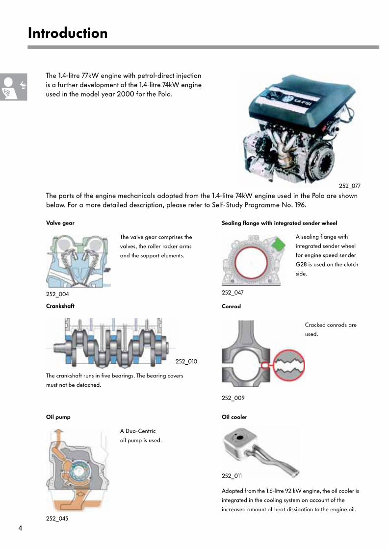
The 1.4-litre 77kW engine with petrol-direct injection is a further development of the 1.4-litre 74kW engine used in the model year 2000 for the Polo.
The parts of the engine mechanicals adopted from the 1.4-litre 74kW engine used in the Polo are shown below. For a more detailed description, please refer to Self-Study Programme No. 196.
A sealing flange with
integrated sender wheel
for engine speed sender
G28 is used on the clutch
side.
252_010
252_047
252_077
Crankshaft
Sealing flange with integrated sender wheel
A Duo-Centric
oil pump is used.
252_045
Oil pump
The crankshaft runs in five bearings. The bearing covers
must not be detached.
The valve gear comprises the
valves, the roller rocker arms
and the support elements.
252_004
Valve gear
252_009
Cracked conrods are
used.
Conrod
252_011
Adopted from the 1.6-litre 92 kW engine, the oil cooler is
integrated in the cooling system on account of the
increased amount of heat dissipation to the engine oil.
Oil cooler

5
Specifications
The 1.4-litre 77kW engine
Maximum power output is 77kW at 6200 rpm. Maximum torque is 130 Nm at an engine speed of 4500 rpm.
The Lupo FSI, like the Lupo 3L, has an ECO mode. In this mode, average fuel consumption is 4.9 l per 100 km in accordance with the MVEG standard. Engine speed is limited to 4000 rpm and full throttle injection quantity is reduced. Maximum power output is 51 kW and maximum torque is 125 Nm at 4000 rpm. The power output and torque figures at engine speeds up to 4000 rpm are approximately 3 % below those shown in the adjacent diagram.
Differences compared with the Lupo 3L
- The Lupo FSI does not have a stop/start func-tion. During stationary phases, therefore, theengine continues to run. This prevents thecatalytic converters cooling down to belowtheir working temperature.
Engine code ARR
Type 4-cylinder inline engine
Valves per cylinder 4
Displacement in cm³ 1390
Bore / stroke in mm 76.5 / 75.6
Compression ratio 11.5 : 1
Engine management Bosch Motronic MED 7.5.10
Fuel Premium unleaded with RON 98
Exhaust gas aftertreatment Lambda control, three-way catalytic converter, NOx storage catalytic converter
Exhaust emission standard EU 4
In the event of a loss of power and torque as well as increased fuel consumption, the engine runs on premium
unleaded RON 95. The increased fuel consumption is the result of the higher sulphur content in the fuel, which is
detrimental to petrol-direct injection engines in particular.
[kW] [Nm]
[rpm] 252_037
- In overrun phases, the clutch is notdisengaged. Consequently, overrun shut-offremains active for as long as possible.

6
Engine mechanicals
The toothed belt drive was adopted from the 1.6-litre 92kW engine of the Polo GTI.
In the main drive, the coolant pump and the inlet camshaft are driven by the crankshaft.A semiautomatic tension pulley and two deflection pulleys stabilise the motion of the toothed belt.
In the secondary drive, the inlet camshaft drives the exhaust camshaft by means of a second toothed belt. The toothed belt is tensioned by a semiautomatic tension pulley.
Toothed belt drive
Coolant pump
Exhaust camshaft
timing belt gear
Inlet camshaft
timing belt gear
Deflection
pulley
Secondary
drive toothed belt
Main drive toothed belt
Crankshaft
timing belt gear
252_049
Secondary
drive tension pulley
Main drive tension
pulleyTDC cylinder 1 mark
Locating bores for the camshaft phasing gear
Deflection
pulley
TDC cylinder 1 mark
Helical cut tooth
7
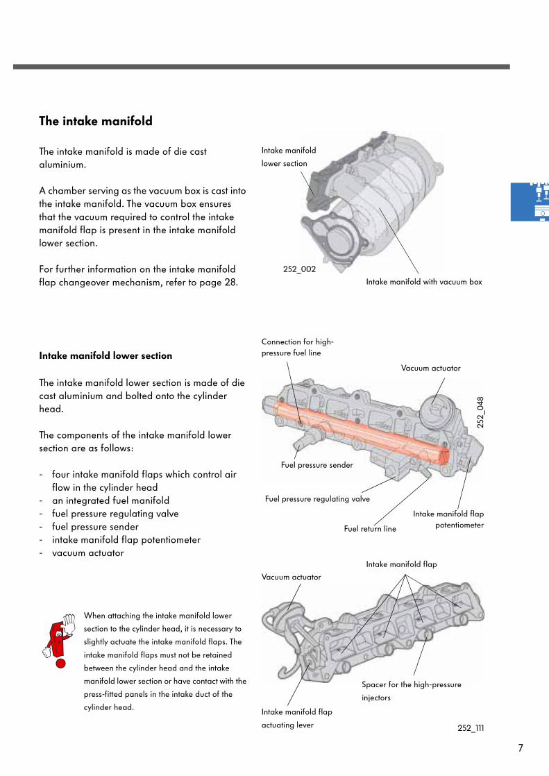
The intake manifold
The intake manifold is made of die cast aluminium.
A chamber serving as the vacuum box is cast into the intake manifold. The vacuum box ensures that the vacuum required to control the intake manifold flap is present in the intake manifold lower section.
For further information on the intake manifold flap changeover mechanism, refer to page 28.
Intake manifold lower section
The intake manifold lower section is made of die cast aluminium and bolted onto the cylinder head.
The components of the intake manifold lower section are as follows:
- four intake manifold flaps which control airflow in the cylinder head
- an integrated fuel manifold - fuel pressure regulating valve- fuel pressure sender- intake manifold flap potentiometer- vacuum actuator
252_002
252_
048
Intake manifold with vacuum box
Vacuum actuator
Intake manifold flap
252_111
Intake manifold flap
actuating lever
Fuel pressure regulating valve
Fuel pressure sender
Connection for high-pressure fuel line
Fuel return line
Intake manifold flappotentiometer
Vacuum actuator
Spacer for the high-pressure
injectors
When attaching the intake manifold lower
section to the cylinder head, it is necessary to
slightly actuate the intake manifold flaps. The
intake manifold flaps must not be retained
between the cylinder head and the intake
manifold lower section or have contact with the
press-fitted panels in the intake duct of the
cylinder head.
Intake manifold
lower section
8
Engine mechanicals
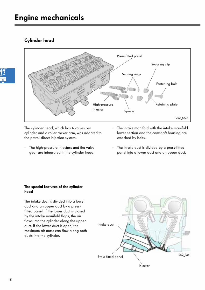
Cylinder head
The cylinder head, which has 4 valves per cylinder and a roller rocker arm, was adapted to the petrol-direct injection system.
- The high-pressure injectors and the valvegear are integrated in the cylinder head.
- The intake manifold with the intake manifoldlower section and the camshaft housing are attached by bolts.
- The intake duct is divided by a press-fittedpanel into a lower duct and an upper duct.
The special features of the cylinder head
The intake duct is divided into a lower duct and an upper duct by a press-fitted panel. If the lower duct is closed by the intake manifold flaps, the air flows into the cylinder along the upper duct. If the lower duct is open, the maximum air mass can flow along both ducts into the cylinder.
252_136
Injector
Intake duct
Press-fitted panel
252_050
High-pressureinjector
Sealing rings
Securing clip
Retaining plate
Spacer
Press-fitted panel
Fastening bolt

9
Triple bearing252_038
252_070
The cams are slipped onto thecamshaft.
The diameter of the hollow shaft is hydraulically widened.
The cams are fixed in place.
Cams
Hollow shaft
Gap
Built-up camshafts are used. The cams are slipped onto a hollow shaft and fixed in place so that they fit exactly. The hollow shaft is then widened hydraulically and the cams are securely located.
Camshafts
The advantages of the two built-up camshafts over cast iron shafts are as follows:
- weight saving of 1.4 kg- twice the flexural rigidity
252_001
The camshaft housing
In the camshaft housing, the two camshafts are mounted on 3 bearings.

10
Engine mechanicals
Camshaft timing control
The 1.4-litre 77kW engine features a variable intake port camshaft timing control. The camshaft timing control is identical to that used in the 1.6-litre 92kW engine of the Polo GTI.
The advantages are:
- improved torque profile- reduced emission and lower fuel consumption
thanks to optimised inner exhaust gasrecirculation.
The camshaft is adjusted at speeds above 1000 rpm depending on engine load and speed. The max. camshaft adjustment is 40° crankshaft angle from the home position in the "advance" direction .
The camshaft is adjusted depending on characteristic maps based on the "engine load" and "engine speed" input signals. The coolant temperature serves as additional information. The engine control unit uses this
information to activate the camshaft timing control and enable advance adjustment or retard adjustment. The Hall sender (G40) recognises the position of the camshaft.
Motronic control unit (J220)
Inlet camshaft timing adjustment
valve (N205)
Hot-film air mass meter (G70)
and intake air temperature
sender (G42)
Engine speed sender (G28)
Coolant temperature sender
(G62)
Hall sender (G40)
Input signals
for the camshaft actual position
for calculating the timing angle
252_148
11
252_071
Inlet camshaft gear
Sealing ring between piston and cylinder
Spacers
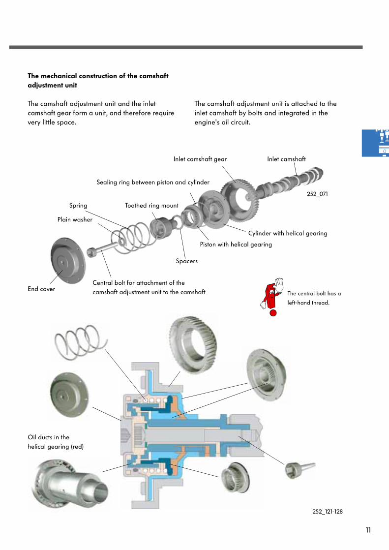
The mechanical construction of the camshaft adjustment unit
The camshaft adjustment unit and the inlet camshaft gear form a unit, and therefore require very little space.
The camshaft adjustment unit is attached to the inlet camshaft by bolts and integrated in the engine's oil circuit.
Cylinder with helical gearing
Piston with helical gearing
Plain washer
Toothed ring mountSpring
End cover
252_121-128
Inlet camshaft
Central bolt for attachment of the camshaft adjustment unit to the camshaft The central bolt has a
left-hand thread.
Oil ducts in the helical gearing (red)

12
Toothed ring mount Piston
Camshaft Cylinder with
helical gearing
Engine mechanicals
Function
The camshaft adjustment unit is attached to the inlet camshaft by bolts. The inlet camshaft is adjusted according to the helical gearing principle.
The means:
The piston in the adjustment unit can be moved in the longitudinal direction by applying oil pressure. The piston is rotated simultaneously because it is mounted on a helical-cut gear.
The toothed ring mount, which the inlet camshaft is bolted to, rotates together with the piston. The position of the camshaft is thus adjusted (see Fig. 252_161).
252_051
Camshaft timing control valve
Duct A
Duct B
Oil inlet
Oil returnpassage
The inlet camshaft timing adjustment valve (N205)
is located on the camshaft housing and integrated in the oil circuit of the engine.
Depending on activation of the camshaft timing control valve, the oil is channelled into various ducts. The ducts are connected to the chambers on both sides of the piston.
"Ignition advance" and "retard adjustment" rake place via duct B and duct A respectively.
Toothed ring mount
Timing belt gear
Piston
Cylinder with helical gearing
Camshaft
252_128
252_161

13
252_058
Activation of the camshaft timing control valve
Configured as a 4/3 way valve, the camshaft timing control valve is activated by the engine control unit. The means that it has four connections and three valve positions are possible.
"Retard adjustment"
For retard adjustment, the oil flows along duct A and into the adjustment unit. The piston is pushed towards the retard stop until the intake port-camshaft has reached the calculated nominal position.The oil on the other side of the piston flows along the other duct and back to the cylinder head.
"Ignition advance"
For ignition advance, the oil is channelled into duct B. The piston is pushed in the direction of the advance stop until the inlet camshaft has reached the calculated nominal position.
The stop position
In this position, the valve closes the two ducts (middle position) leading to the camshaft adjustment unit. Oil can neither flow in nor out. Because the piston remains in this position, the camshaft timing is not adjusted towards "advance" or "retard".
252_059
Duct A
Duct B
In the starting position, the piston is pushed towards the retard stop by the spring when the engine is started. This eliminates noise.
Inlet camshaft timing
adjustment valve N205
Inlet camshaft timing
adjustment valve N205
Retard stop
Advance stop

14
Engine mechanicals
The engine mechanicals are made of a die cast aluminium alloy. For the first time, plasma-coated cylinder liners are used in an engine.
The advantages of this coating are:
- The low layer thickness of 0.085 mm reduces the weight compared to a cylinder block with press-fitted cast ironcylinder bush by approx. 1 kg.
- A plasma-coated cylinder linerreduces both friction and wear.
Cylinder block
252_007
Cylinder wall
Coating powder feed50% alloyed steel, 50% molybdenum
Coating
Plasma jet temp.: approx. 11,700°C
Flow rate = 400-600 m/s
Hydrogen + argon
Anode
Anode
Hydrogen + argon
Speed of application of coating powder:
approx. 80-150 m/s
Temperature of coating powder: approx. 2,500°C
Cathode
The principle of plasma coating
The plasma gas flows through the nozzle outlet and is ignited by an electric arc. In the process, it is heated to a temperature of approx. 11,700°C and enters the plasma state. The gas is accelerated to a max. velocity of 600 m/s .
The coating powder is sprayed into this plasma jet and thus melted. It is heated to a temperature of approx. 2,500°C and accelerated up to 150 m/s.
Nozzle outlet
The plasma burner moves along the cylinder wall while rotating.
252_131
The particles penetrate surface unevenness in the cylinder wall when they impinge on the wall in a liquid state. The kinetic energy is converted into plastic deformation. Solidification of the particles creates a positive bond between the coating and the
cylinder wall. In addition, shrinkage stresses build up within the coating and produce a positive bonding between the coating and the cylinder wall.
15
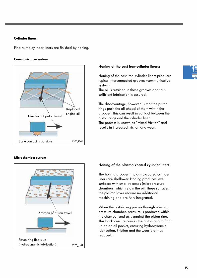
Cylinder liners
Honing of the cast iron-cylinder liners:
Honing of the cast iron-cylinder liners produces typical interconnected grooves (communicative system). The oil is retained in these grooves and thus sufficient lubrication is assured.
The disadvantage, however, is that the piston rings push the oil ahead of them within the grooves. This can result in contact between the piston rings and the cylinder liner. The process is known as "mixed friction" and results in increased friction and wear.
Communicative system
Microchamber system
Honing of the plasma-coated cylinder liners:
The honing grooves in plasma-coated cylinder liners are shallower. Honing produces level surfaces with small recesses (micropressure chambers) which retain the oil. These surfaces in the plasma layer require no additional machining and are fully integrated.
When the piston ring passes through a micro-pressure chamber, pressure is produced within the chamber and acts against the piston ring. This backpressure causes the piston ring to float up on an oil pocket, ensuring hydrodynamic lubrication. Friction and the wear are thus reduced.
Finally, the cylinder liners are finished by honing.
252_041
Displaced engine oil
Direction of piston travel
Edge contact is possible
252_041
Direction of piston travel
Piston ring floats up(hydrodynamic lubrication)

16
Engine mechanicals
The crankcase breather
The crankcase breather comprises an oil separator on the cylinder block and a low-pressure valve on the intake manifold. It prevents oil and unburned hydrocarbons from entering the atmosphere.
The gases are drawn in from the crankcase through the vacuum present in the intake manifold.
The gases initially flow through the oil separator, where the oil is collected and recirculated within the crankcase. The remaining vapours are channelled into the intake manifold via a low-pressure valve and from here into the combustion chamber.
252_130
252_135
Low-pressure valve
Oil separator
The low-pressure valve
This valve maintains a constant vacuum and ensures good crankcase ventilation. The condensate and the fuel entrained in the oil are thus extracted and the quality of the oil is improved.The vacuum must not be too high, because otherwise the sealing rings will open inwards allowing dirt to enter the crankcase.
Function
The low-pressure valve is divided into two chambers by a membrane. One chamber leads into the open and the other chamber leads into the intake manifold and the oil separator.
With increasing vacuum inside the intake manifold, the vacuum inside the crankcase would also increase. To prevent this, the cross-section leading into the intake manifold is adjusted as a function of pressure. A constant gas flow is thus maintained.
The pressure differential between the two chambers is
low high
Connection to intake manifold
Connection to oil separator
Duct leading intothe open air
17
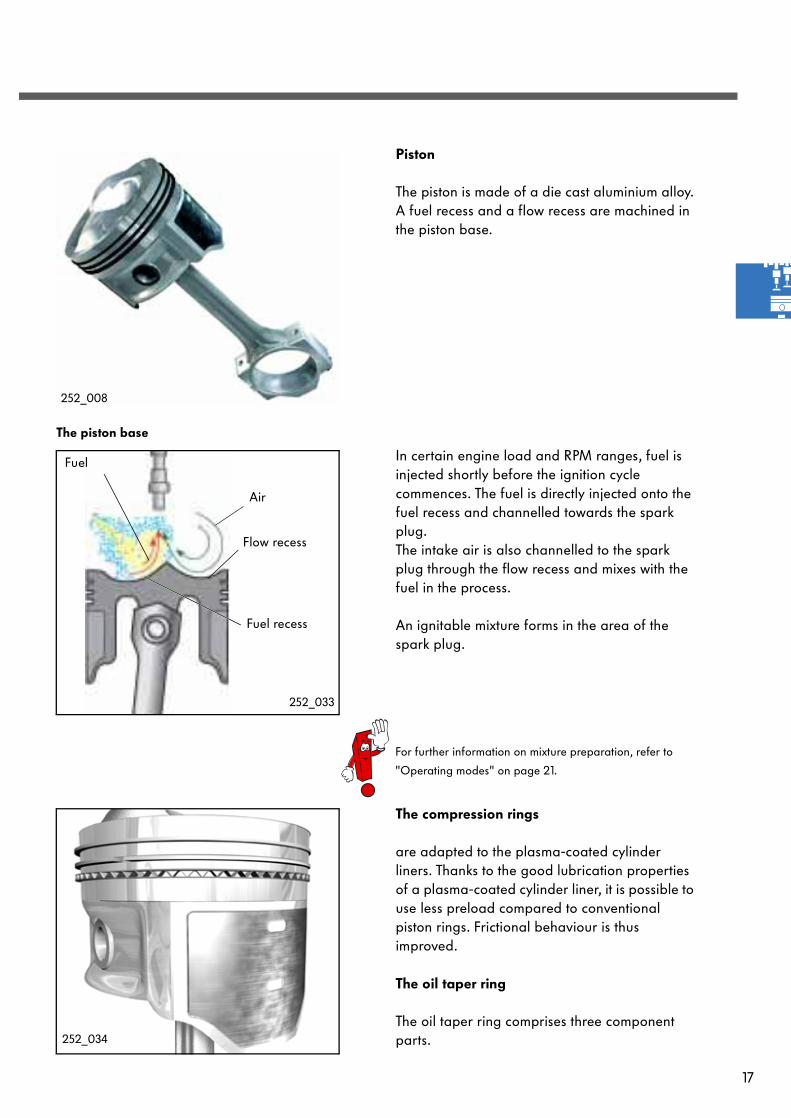
Fuel recess
Air
Flow recess
Fuel
252_033
Piston
The piston is made of a die cast aluminium alloy. A fuel recess and a flow recess are machined in the piston base.
The compression rings
are adapted to the plasma-coated cylinder liners. Thanks to the good lubrication properties of a plasma-coated cylinder liner, it is possible to use less preload compared to conventional piston rings. Frictional behaviour is thus improved.
The oil taper ring
The oil taper ring comprises three component parts.
The piston base
For further information on mixture preparation, refer to
"Operating modes" on page 21.
252_008
In certain engine load and RPM ranges, fuel is injected shortly before the ignition cycle commences. The fuel is directly injected onto the fuel recess and channelled towards the spark plug. The intake air is also channelled to the spark plug through the flow recess and mixes with the fuel in the process.
An ignitable mixture forms in the area of the spark plug.
252_034
18
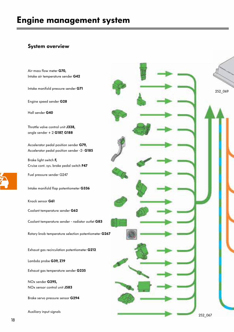
Engine management system
Intake manifold pressure sender G71
System overview
Exhaust gas recirculation potentiometer G212
Intake manifold flap potentiometer G336
Engine speed sender G28
Fuel pressure sender G247
Lambda probe G39, Z19
Throttle valve control unit J338,
angle sender + 2 G187, G188
Coolant temperature sender G62
Hall sender G40
Coolant temperature sender - radiator outlet G83
Exhaust gas temperature sender G235
Brake light switch F,
Cruise cont. sys. brake pedal switch F47
NOx sender G295,
NOx sensor control unit J583
Air-mass flow meter G70,
Intake air temperature sender G42
Brake servo pressure sensor G294
Accelerator pedal position sender G79,
Accelerator pedal position sender -2- G185
Knock sensor G61
252_069
252_067
Rotary knob temperature selection potentiometer G267
Auxiliary input signals

19
Injector, cylinders 1-4 N30-33
Motronic control unit J220
Fuel pump relay J17
Fuel pump G6
Activated charcoal filter system solenoid
valve 1 N80
Ignition coils 1 - 4 N70, N127, N291. N292
Motronic current supply relay J271
Mapped-controlled engine cooling
thermostat F265
Fuel pressure regulating valve N276
Intake manifold flap air flow control valve
N316
Inlet camshaft timing adjustment valve N205
Fuel metering valve N290
Throttle valve control unit J338
Throttle valve drive G186
Lambda probe heater Z19
Exhaust gas recirculation valve N18
NOx sender heater Z44
252_068
Electronic manual gearbox
control unit J514
Airbag control unit J234
ABS control unit
J104
Auxiliary output signals
Control unit with display in dash
panel insert J285
Diagnostic connection

20
Engine management system
Engine control unit
252_075
The engine control unit is housed in the plenum chamber and has 121 pins.
The engine control unit in question is the Bosch Motronic MED 7.5.10 engine management system, an advanced development of the Bosch Motronic ME 7.5.10 featuring "electric throttle control".
The designation MED 7.5.10 stands for:
M = Motronic
E = Electric throttle control
D = Direct injection
7. = Version
5.10 = Development level
Bosch Motronic MED 7.5.10 also includes a petrol-direct injection function.
With this system, the fuel is injected directly into the cylinder and no longer into the intake manifold.
21
Operating modes
Stratified charge mode
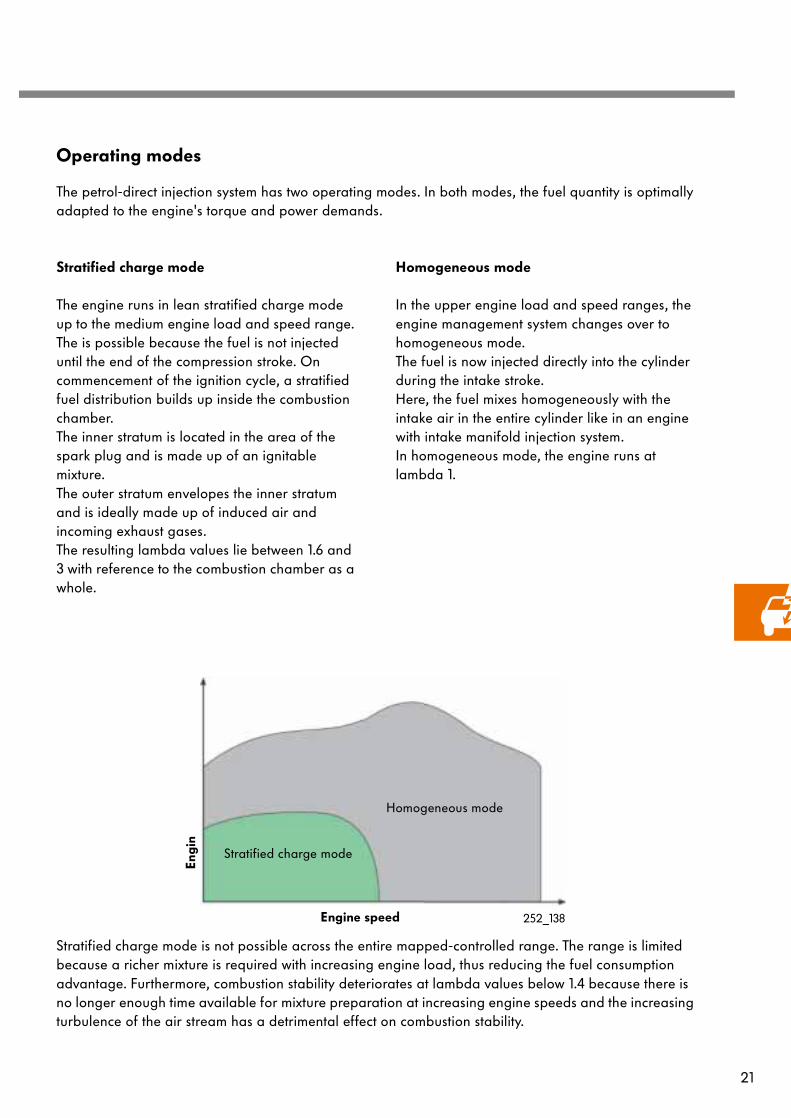
The engine runs in lean stratified charge mode up to the medium engine load and speed range. The is possible because the fuel is not injected until the end of the compression stroke. On commencement of the ignition cycle, a stratified fuel distribution builds up inside the combustion chamber. The inner stratum is located in the area of the spark plug and is made up of an ignitable mixture. The outer stratum envelopes the inner stratum and is ideally made up of induced air and incoming exhaust gases.The resulting lambda values lie between 1.6 and 3 with reference to the combustion chamber as a whole.
Engi
n
Engine speed
Stratified charge mode
Homogeneous mode
The petrol-direct injection system has two operating modes. In both modes, the fuel quantity is optimally adapted to the engine's torque and power demands.
252_138
Stratified charge mode is not possible across the entire mapped-controlled range. The range is limited because a richer mixture is required with increasing engine load, thus reducing the fuel consumption advantage. Furthermore, combustion stability deteriorates at lambda values below 1.4 because there is no longer enough time available for mixture preparation at increasing engine speeds and the increasing turbulence of the air stream has a detrimental effect on combustion stability.
Homogeneous mode
In the upper engine load and speed ranges, the engine management system changes over to homogeneous mode.The fuel is now injected directly into the cylinder during the intake stroke. Here, the fuel mixes homogeneously with the intake air in the entire cylinder like in an engine with intake manifold injection system.In homogeneous mode, the engine runs at lambda 1.

22
Engine management system
Stratified charge mode
Several conditions have to be met before the engine management system can enter stratified charge mode:
- the engine is in the corresponding engine load and speed ranges, - there must not be any emission-relevant faults in the system,- coolant temperature must be above 50°C,- the temperature of the NOx storage catalytic converter must be between 250°C and 500°C and- the intake manifold flap must be closed.
The throttle valve is opened as widely as possible to minimize throttle losses.
The intake manifold flap closes the lower duct in the cylinder head. As a result, the intake air is accelerated and tumbles into the cylinder.
Intake manifold flap
High pressure fuel injector
252_017
Throttle valve
The tumble effect is reinforced in the cylinder by the special shape of the piston base.
252_019
If these conditions are met, the engine can now enter stratified charge mode.
23
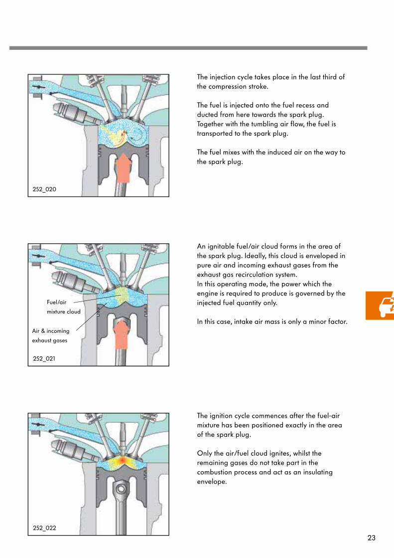
The injection cycle takes place in the last third of the compression stroke.
The fuel is injected onto the fuel recess and ducted from here towards the spark plug. Together with the tumbling air flow, the fuel is transported to the spark plug.
The fuel mixes with the induced air on the way to the spark plug.
An ignitable fuel/air cloud forms in the area of the spark plug. Ideally, this cloud is enveloped in pure air and incoming exhaust gases from the exhaust gas recirculation system. In this operating mode, the power which the engine is required to produce is governed by the injected fuel quantity only.
In this case, intake air mass is only a minor factor.
The ignition cycle commences after the fuel-air mixture has been positioned exactly in the area of the spark plug.
Only the air/fuel cloud ignites, whilst the remaining gases do not take part in the combustion process and act as an insulating envelope.
252_020
252_021
Fuel/air
mixture cloud
Air & incoming
exhaust gases
252_022

24
Engine management system
The throttle valve is opened in accordance with the accelerator pedal position . Following the changeover from stratified charge mode to homogeneous mode, the lower duct in the cylinder head remains closed. As a result, the intake air continues to tumble into the cylinder, which is beneficial to mixture formation. With increasing engine load and engine speed, the air mass which can only be induced via the upper duct would no longer be sufficient. In this case, the intake manifold flap also releases the lower duct (see Fig. on left).
The fuel is injected directly into the cylinder during the intake stroke.
Homogeneous mode
Homogeneous mode is comparable to operation of an engine with an intake manifold injection system. The main difference is that the fuel is injected directly into the cylinder in the case of the petrol-direct injection engine.
252_023
252_025
The directly injected fuel is vaporized in the cylinder and extracts a portion of the heat from the intake air. As a result, the compression ratio can increase to 11.5:1 without causing knocking combustion.

25
By injecting the fuel during the intake stroke, a relatively large amount of time is available for mixture formation. As a result, a homogeneous (uniformly distributed) mixture of injected fuel and induced air forms inside the cylinder. In the combustion chamber, the lambda value = 1.
252_026
252_027
The combustion process takes place throughout the combustion chamber.

26
Engine management system
The intake system
New features include:
- A hot-film air mass meter (G70) withintake air temperature sender (G42),
- an electrical exhaust gas recirculation valve (N18) with the exhaust gas recirculationpotentiometer (G212),
- an intake manifold pressure sender (G71), - an intake manifold with a vacuum-
reservoir for the intake manifold flapchangeover mechanism
- an intake manifold flap changeovermechanism in combination with intakemanifold flap air flow control valve (N316)and the intake manifold flappotentiometer (G336).
Hot-film air mass meter (G70) with intake air temperature sender (G42)
Throttle valve control unit (J338)
Exhaust gas recirculation valve (N18) with exhaust gas recirculation potentiometer (G212)
Intake manifold
Non-return valve
Intake manifold flap valve (N316)
Activated charcoal filter system solenoid valve 1 (N80)
Activated charcoal canister
Intake manifold pressure sender (G71)
was redeveloped and adapted to the requirements of a petrol-direct injection engine. As a result, it was possible to increase the exhaust gas recirculation rate to max. 35% and control air flow in the cylinder.
27
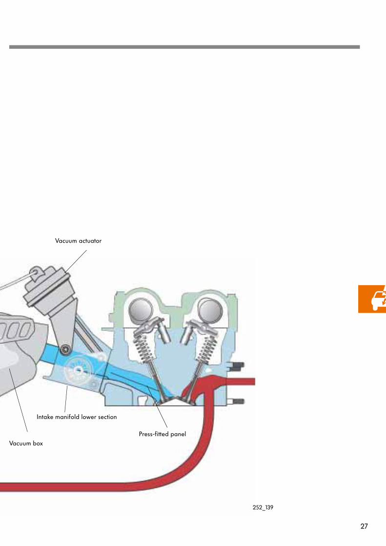
Vacuum actuator
Intake manifold lower section
Press-fitted panelVacuum box
252_139

28
Engine management system
The engine management system allows the air flow in the cylinders to be controlled depending on operating point.
The engine management system consists of:
- a non-return valve- a vacuum box in the intake manifold- an intake manifold flap valve- a vacuum actuator- four intake manifold flaps in the intake
manifold lower section- an intake manifold flap potentiometer- the press-fitted panels in the cylinder head
Vacuum actuator
252_159
Non-return valve
Intake manifold flap valve
Intake manifold
lower section
Intake manifold
flaps
Intake air
Intake manifold
Vacuum box
Intake manifold flap potentiometer
Intake manifold flap changeover mechanism

29
A vacuum builds up in the intake manifold when fresh air is induced. Because the vacuum box and the intake path are directly interconnected, a vacuum also develops in the intake path.
The non-return valve maintains the vacuum in the vacuum box after the engine is turned off.
Intake air
Vacuum actuatorIntake manifold flap
air control valve
Non-return valve
Vacuum box
Function
The intake manifold flap valve is located on the vacuum box. It is activated by the engine control unit and switches the vacuum from the vacuum box through to the vacuum actuator of the intake manifold flap. The vacuum actuator in turn actuates the intake manifold flap.
Intake manifold flaps
Intake manifold flap
potentiometer
Because the position of the intake manifold flap affects mixture formation, and hence also emission levels, diagnosis of the intake manifold flaps must be performed. The diagnosis procedure is performed by the intake manifold flap potentiometer.
252_157
252_158
252_158

30
Engine management system
Intake manifold flap actuated
Intake manifold flap not actuated
In homogeneous mode, the intake manifold flap is not actuated under high engine load, and the two ducts are open.
By virtue of the larger cross-section of the intake duct, the engine is able to draw in the air mass required to generate produce high engine torque.
In stratified charge mode and, in part, in homogeneous mode, the intake manifold flap is actuated and the lower duct in the cylinder head is closed. As a result, the intake air only flows along the narrow upper duct, increasing the flow rate. In addition, the upper duct is designed in such a way that the intake air tumbles into the cylinder.
The tumble air flow has the following effects:
- In stratified charge mode, the fuel is channelled to the spark plug. The fuel/airmixture forms as the fuel flows towards thespark plug.
- Mixture formation supported in severaloperating ranges in homogeneous mode. The movement of the charge ensures a highly ignitable fuel/air mixture and stablecombustion.
252_019
252_023
31
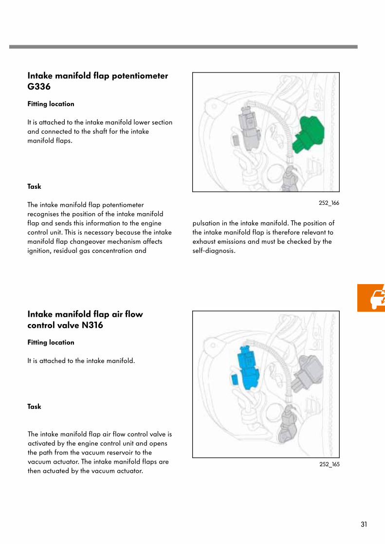
Intake manifold flap potentiometer G336
The intake manifold flap potentiometer recognises the position of the intake manifold flap and sends this information to the engine control unit. This is necessary because the intake manifold flap changeover mechanism affects ignition, residual gas concentration and
Task
252_166
Intake manifold flap air flow control valve N316
The intake manifold flap air flow control valve is activated by the engine control unit and opens the path from the vacuum reservoir to the vacuum actuator. The intake manifold flaps are then actuated by the vacuum actuator.
Task
252_165
pulsation in the intake manifold. The position of the intake manifold flap is therefore relevant to exhaust emissions and must be checked by the self-diagnosis.
Fitting location
It is attached to the intake manifold lower section and connected to the shaft for the intake manifold flaps.
Fitting location
It is attached to the intake manifold.

32
Engine management system
Air-mass flow meter G70 with intake air temperature sender G42
enables the engine control unit to accurately determine air mass intake, and hence engine load. The intake air temperature is sued for exact air mass determination (for further information, refer to SSP 195).
Task 252_164
Intake manifold pressure sender G71
intake manifold pressure rises. The engine control unit calculates the exhaust gas recirculation rate from this differential between the intake manifold pressure (fresh air) and the intake manifold pressure (fresh air + exhaust gas). The exhaust gas recirculation rate can consequently be increased, because a large margin of safety to the operating limit is not required.
Task
The intake manifold pressure sender gauges the pressure inside the intake manifold and sends a corresponding signal to the engine control unit. The engine control unit uses this signal to compute the exhaust gas recirculation rate. From the information supplied by the hot-film air mass meter, the engine control unit knows how much fresh air was induced and, accordingly, how high the intake manifold pressure is required to be. If exhaust gases are admitted, however, the actual
To obtain as exact an engine load signal as possible, an engine air-mass flow meter with reverse flow recognition is used. This device measures not only the air volume which is drawn in; it also recognises how much air flows back when the valves are opened and closed. This
Fitting location
The two sensors are a single component and are located in the intake path upstream of the throttle valve control unit.
Fitting location
It is attached to the intake manifold.
252_167

33
252_163
Brake servo pressure sensor G294
The brake servo pressure sensor gauges the pressure in the line, and hence the pressure in the brake servo. A corresponding voltage signal is sent to the engine control unit. The engine control unit determines whether sufficient vacuum is available for the brake servo. The is necessary because the throttle valve is wide open in stratified charge mode, and consequently there is very little vacuum inside the intake manifold. If the driver now operates the brake several times in succession, the vacuum accumulated in the brake servo will no longer be sufficient. In this case, the driver would have to apply more pressure to the brake. To prevent this, the throttle valve is closed until vacuum is again sufficient to operate the brake servo.In an emergency, the vehicle changes over to homogeneous mode.
Task
Fitting location
It is located in the line between the intake manifold and the brake servo.
34
Engine management system
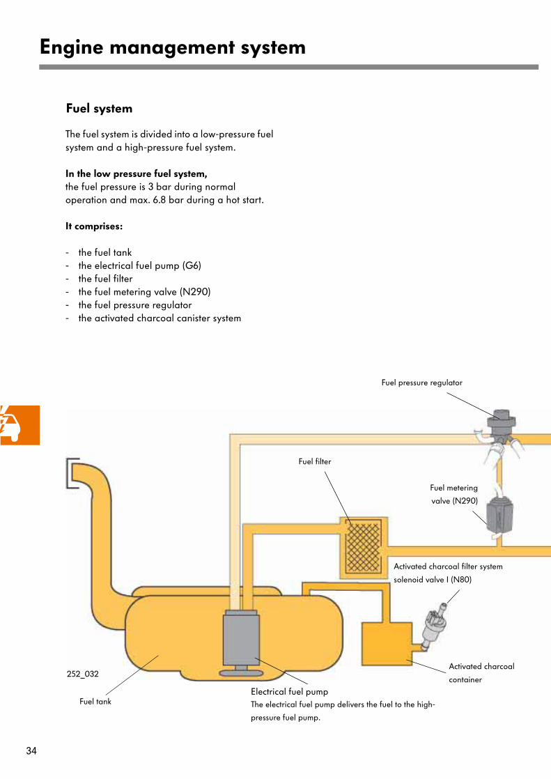
Fuel system
The fuel system is divided into a low-pressure fuel system and a high-pressure fuel system.
In the low pressure fuel system,the fuel pressure is 3 bar during normal operation and max. 6.8 bar during a hot start.
It comprises:
- the fuel tank- the electrical fuel pump (G6)- the fuel filter- the fuel metering valve (N290)- the fuel pressure regulator- the activated charcoal canister system
Fuel pressure regulator
Fuel metering
valve (N290)
Fuel filter
Electrical fuel pump The electrical fuel pump delivers the fuel to the high-
pressure fuel pump.
Fuel tank
Activated charcoal filter system
solenoid valve I (N80)
Activated charcoal
container252_032

35
Fuel railHigh-pressure
fuel pump
Fuel pressure regulating valve
(N276)
Fuel pressure sender
(G247)
High-pressure injectors
(N30-N33)
252_066
In the high-pressure fuel system, the fuel pressure is between 50 and 100 bar, depending on the characteristic map.
It comprises the following components:
- the high-pressure fuel pump - a high-pressure fuel line- the fuel manifold- the fuel pressure sender (G247)- the fuel pressure regulating valve (N276)- the high-pressure injectors (N30-N33)
High-pressure fuel line depressurised
3-6.8 bar
50 - 100 bar

36
Engine management system
The fuel pressure regulator
is located on the suspension strut tower. It sets the fuel pressure in the low pressure fuel system to3 bar by means of a spring-loaded diaphragm valve. In the process, the cross-section to the fuel return line is enlarged or reduced as a function of pressure.
The fuel metering valve (N290)
is attached to the suspension strut tower.
During normal operation, the valve is permanently open and releases the return line to the fuel pressure regulator.
If
- the coolant temperature is higher than 115°Cand
- the intake air temperature is higher than 50°C,
at engine start-up, then the engine control unit closes the valve for approx. 50 seconds. As a result, the path to the fuel return line is blocked on the suction side of the high-pressure fuel pump. The pressure in the low pressure fuel system now rises to the maximum feed pressure of the electrical fuel pump. Max. feed pressure is governed by a pressure limiting valve in the fuel pomp, and must not exceed 6.8 bar.This pressure increase prevents vapour bubble formation on the suction side of the high-pressure fuel pump and ensures correct high-pressure build up.
252_060
252_061

37
The high-pressure fuel pump
is attached to the camshaft housing.
It is a 3-cylinder radial piston pump and is driven by the inlet camshaft. It pumps the fuel along a high-pressure fuel line to the fuel manifold. The high-pressure fuel pump increases the pressure from the low pressure fuel system from 3 bar to approximately 100 bar. The pressure in the fuel manifold is set via the fuel pressure regulating valve.
252_162
The fuel manifold
is integrated in the intake manifold lower section.
The task of the fuel manifold is to store the fuel under high pressure and distribute it via the high-pressure injectors to the individual cylinders.
252_064
The fuel pressure sender (G247)
is located on the intake manifold lower section and is screwed into the fuel manifold.
It gauges the momentary fuel pressure in the fuel manifold and sends this information to the engine control unit in the form of a voltage signal. Regulation of the fuel pressure in the fuel manifold then commences.
252_048
252_052

38
Jet angle
Angle of inclination of jet
252_160
Engine management system
The fuel pressure regulating valve (N276)
is screwed into the intake manifold lower section in the fuel manifold.
The regulating valve regulates the fuel pressure in the fuel manifold between 50 and 100 bar. It is pulse-actuated by the engine control unit, and sets the pressure in the fuel manifold in accordance with discharge quantity.
252_048
252_053
The high-pressure injectors (N30-33)
are positioned in the cylinder head and inject fuel directly into the combustion chamber.
The injectors are single-hole injectors; the jet angle is 70° and the angle of inclination of the jet is 20°.
The injectors are also adapted to the requirements of a petrol-direct injection engine. These are, firstly, the higher fuel pressure and, secondly, the reduced amount of time available to the injection cycle in stratified charge mode .
The injectors are sealed off from the combustion chamber by a Teflon sealing ring.
252_100
Teflon sealing ring
39
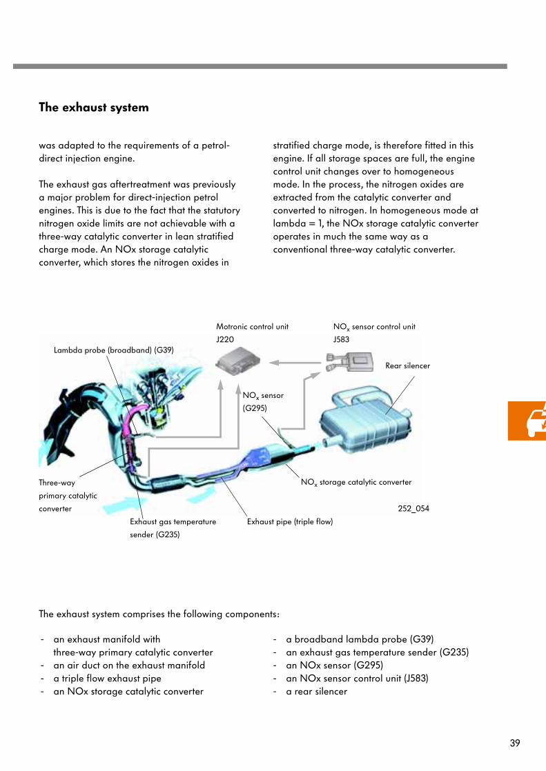
The exhaust system
- an exhaust manifold with three-way primary catalytic converter
- an air duct on the exhaust manifold- a triple flow exhaust pipe- an NOx storage catalytic converter
- a broadband lambda probe (G39)- an exhaust gas temperature sender (G235)- an NOx sensor (G295)- an NOx sensor control unit (J583)- a rear silencer
Exhaust pipe (triple flow)
Lambda probe (broadband) (G39)
Three-way
primary catalytic
converter
Exhaust gas temperature
sender (G235)
NOx storage catalytic converter
NOx sensor
(G295)
Rear silencer
252_054
was adapted to the requirements of a petrol-direct injection engine.
The exhaust gas aftertreatment was previously a major problem for direct-injection petrol engines. This is due to the fact that the statutory nitrogen oxide limits are not achievable with a three-way catalytic converter in lean stratified charge mode. An NOx storage catalytic converter, which stores the nitrogen oxides in
stratified charge mode, is therefore fitted in this engine. If all storage spaces are full, the engine control unit changes over to homogeneous mode. In the process, the nitrogen oxides are extracted from the catalytic converter and converted to nitrogen. In homogeneous mode at lambda = 1, the NOx storage catalytic converter operates in much the same way as a conventional three-way catalytic converter.
The exhaust system comprises the following components:
Motronic control unit
J220
NOx sensor control unit
J583

40
Engine management system
Exhaust manifold cooling system
Fresh air is directed to the exhaust manifold at the front end of the vehicle and thus the exhaust gas is cooled.
As a result, it is possible to change over to the consumption-optimised stratified charge mode as quickly as possible after trips involving high exhaust gas temperatures.
252_140
Exhaust gas cooling system
The NOx storage catalytic converter can only store nitrogen oxides (NOx) within a temperature range between 250°C and 500°C. The exhaust gas is cooled so that it is in this temperature range as often and long as possible. The exhaust gas is cooled firstly by an exhaust manifold cooling system and, secondly, by a triple flow exhaust pipe.
The triple flow exhaust pipe
is located upstream of the NOx storage catalytic converter. It also serves to reduce the temperature of the exhaust gases and NOx storage catalytic converter. Its larger surface area increases heat dissipation to the atmosphere and reduces the exhaust gas temperature.
252_015

41
252_057
252_055
Temperature sensor
Fitting location
The temperature sensor is located downstream of the primary catalytic converter.
Task
It gauges the exhaust gas temperature and sends this information to the engine control unit. The engine control unit calculates the temperature in the NOx storage catalytic converter from this information.
The is necessary because:
- the NOx storage catalytic converter can only store nitrogen oxides at temperaturesbetween 250°C and 500°C. For this reason,stratified charge mode may only be selected
in this temperature range.
- the sulphur from the fuel is also collected involuntarily in the NOx storage catalytic con-verter. To extract the sulphur again, thetemperature in the storage catalytic convertermust rise above 650°C.
252_062
Broadband lambda probe (primary catalytic converter)
Fitting location
It is located on the exhaust manifold.
Task
Using the broadband lambda probe, the oxygen content in the exhaust gas can be defined over a wide measurement range.In the event of deviations from the setpoint, the injection time is corrected.

42
Engine management system
The NOx storage catalytic converter
has a similar mechanical construction to a conventional three-way catalytic converter. However, barium oxide was added to the converter. Barium oxide stores nitrogen oxides at temperatures between 250°C and 500°C by forming nitrates. The is necessary because a three-way catalytic converter can only convert a small proportion of the nitrogen oxides into nitrogen in lean stratified charge mode.
The engine control unit detects when the storage spaces are full and changes over to regeneration mode. This is the only way to maintain the exhaust emission limits.
For further information regarding regeneration mode, refer to pages 44 and 45.
252_141
Due to its chemical similarity with nitrogen oxides, the sulphur contained in the fuel is also stored as a sulphate. Because of this, it occupies the storage spaces of the nitrogen oxides and requires to be frequently regenerated.
252_142
The primary catalytic converter
is a three-way catalytic converter and is located in the exhaust manifold. This near-engine layout is necessary so that the catalytic converter can reach its operating temperature and exhaust gas treatment can begin as quickly as possible. This is the only way to achieve the strict exhaust emission limits.

43
NOx sensor control unit
Fitting location
It is located on the vehicle underbody near to the NOx sensor. The layout near to the engine prevents external interference falsifying the signals of the NOx sensor.
Task
In the NOx sensor control unit, the signals are processed and sent to the engine control unit. If the engine control unit recognises that the storage capacity of the NOx storage catalytic converter is exhausted, it changes over to regeneration mode.
252_073
NOx sensor
Fitting location
It is located downstream of the NOx storage catalytic converter.
Task
The NOx sensor is used to determine the nitrogen oxide (NOx) and oxygen content in the exhaust gas according to the functional principle of a broadband lambda probe.
- The remaining storage capacity of the NOx storage catalytic converter is determined on the basis of nitrogen oxidecontent.
- Oxygen content is still used to monitor the functioning of the catalytic converter and adapt the injection quantity if necessary.
The signals are transmitted from the NOx sensor to the NOx sensor control unit.
252_056
252_016
44
Engine management system
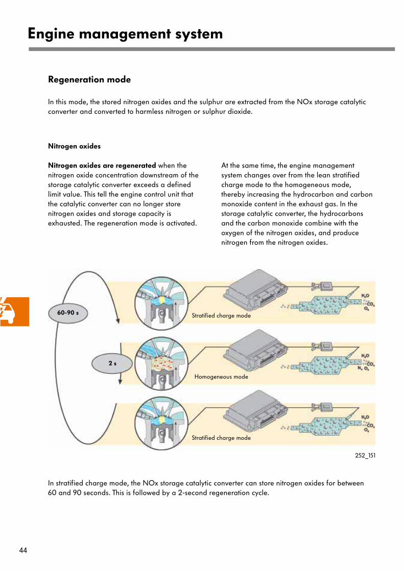
Nitrogen oxides
Nitrogen oxides are regenerated when the nitrogen oxide concentration downstream of the storage catalytic converter exceeds a defined limit value. This tell the engine control unit that the catalytic converter can no longer store nitrogen oxides and storage capacity is exhausted. The regeneration mode is activated.
At the same time, the engine management system changes over from the lean stratified charge mode to the homogeneous mode, thereby increasing the hydrocarbon and carbon monoxide content in the exhaust gas. In the storage catalytic converter, the hydrocarbons and the carbon monoxide combine with the oxygen of the nitrogen oxides, and produce nitrogen from the nitrogen oxides.
Regeneration mode
In this mode, the stored nitrogen oxides and the sulphur are extracted from the NOx storage catalytic converter and converted to harmless nitrogen or sulphur dioxide.
In stratified charge mode, the NOx storage catalytic converter can store nitrogen oxides for between 60 and 90 seconds. This is followed by a 2-second regeneration cycle.
60-90 s
2 s
Stratified charge mode
Homogeneous mode
Stratified charge mode
252_151

45
To minimise fuel consumption by sulphur regeneration, a sulphur-free fuel (Shell Optimax) was developed by Shell in association with Volkswagen. With RON 99, Shell Optimax offers the following advantages:
- lower fuel consumption because fewer sulphur regeneration cycles are needed,- reduced pollutant emissions through a new processing method and sulphur elimination , - improved acceleration due to higher octane number (RON 99) and- fewer deposits in the engine through special fuel additives.
Sulphur regeneration
The regeneration of sulphur is slightly more complex because the sulphur is more temperature resistant and remains stored in the catalytic converter during the nitrogen oxide regeneration cycle. The fuel is desulphurised if the nitrogen oxide concentration downstream of the NOx storage catalytic converter reaches a defined value within ever-decreasing time intervals . From this, the engine control unit concludes that the memory locations of the catalytic converter are free from sulphur and the nitrogen oxides can no longer be stored.
The fuel desulphurisation cycle takes approx. 2 minutes, whereby:
- the engine management system changes overfrom stratified charge mode to homogeneous mode and
- the temperature of the storage catalytic con-verter is increased to above 650°C byadjustingthe ignition timing towards "retard".
Only then is the stored sulphur converted to sulphur dioxide SO2.
2 minutes
Stratified charge mode
Homogeneous mode
Stratified charge mode
252_152
Ignition point "RETARD"
Trips involving high engine load and engine speed lead automatically to desulphurisation because the necessary desulphurisation temperature is reached in the NOx storage catalytic converter.

46
252_144
Exhaust gas recirculation valve (N1Connecting tube
Engine management system
Exhaust gas recirculation system
This justifies the use of a NOx storage catalytic converter. This is because the incoming exhaust gases reduce combustion temperature and nitrogen oxide formation.
Exhaust gas recirculation is performed
- continuously in stratified charge mode and - up to an engine speed of 4000 rpm and at
medium engine load in homogeneous mode,but not when the engine is running at idlingspeed.
The recirculated exhaust gas quantity is max. 35% of the total amount of gas induced.
As a result, the catalytic converter is able to store nitrogen oxides over a longer period of time and does not required to be regenerated as often.
The vehicle can be operated in the fuel-saving stratified charge mode for longer.
The exhaust gas recirculation valve (N18)
is attached to the intake manifold by bolts. It was redesigned to allow high exhaust gas recirculation rates.
It comprises a housing with:
- a throttle valve, - an electric motor and- the exhaust gas
recirculation potentiometer (G212).
The exhaust gases are extracted via a connecting tube on the head of the fourth cylinder.The engine control unit activates the electric motor depending on the characteristic map and actuates a throttle valve.Depending on throttle valve position, a defined quantity of exhaust gas now flows into the intake manifold and mixes with the fresh air induced.
The exhaust gas recirculation potentiometer in the housing cover recognises the position of the throttle valve. This allows the exhaust gas recirculation valve to be diagnosed.
252_108
Electric motorThrottle valve
Exhaust gas
recirculation potentiometer (G212)
47
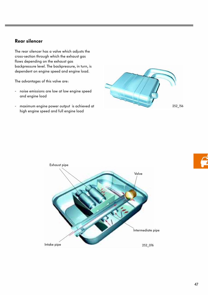
252_076Intake pipe
Valve
Exhaust pipe
Intermediate pipe
Rear silencer
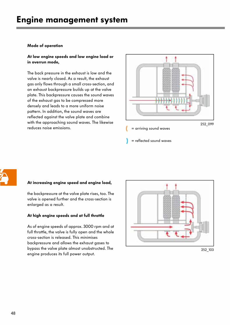
The rear silencer has a valve which adjusts the cross-section through which the exhaust gas flows depending on the exhaust gas backpressure level. The backpressure, in turn, is dependent on engine speed and engine load.
The advantages of this valve are:
- noise emissions are low at low engine speedand engine load
- maximum engine power output is achieved athigh engine speed and full engine load
252_156
48
Engine management system
Mode of operation
At low engine speeds and low engine load or in overrun mode,
The back pressure in the exhaust is low and the valve is nearly closed. As a result, the exhaust gas only flows through a small cross-section, and an exhaust backpressure builds up at the valve plate. This backpressure causes the sound waves of the exhaust gas to be compressed more densely and leads to a more uniform noise pattern. In addition, the sound waves are reflected against the valve plate and combine with the approaching sound waves. The likewise reduces noise emissions.
252_099
252_103
At increasing engine speed and engine load,
the backpressure at the valve plate rises, too. The valve is opened further and the cross-section is enlarged as a result.
At high engine speeds and at full throttle
As of engine speeds of approx. 3000 rpm and at full throttle, the valve is fully open and the whole cross-section is released. This minimises backpressure and allows the exhaust gases to bypass the valve plate almost unobstructed. The engine produces its full power output.
= arriving sound waves
= reflected sound waves

49
Cooling system depending on
The 1.4-litre 77kW engine has an electronically controlled cooling system. This system adjusted the coolant temperature to between 85°C and 110°C depending on the characteristic map.
The temperature in the cooling system is dependent on the coolant quantity which flows through the radiator and is cooled here. The quantity of coolant is defined by the mapped-
controlled engine cooling thermostat . Depending on temperature, the cross-section leading from the radiator to the coolant distributor housing is enlarged or reduced.
In the part-throttle range,
the coolant temperature is between 95°C and 110°C. The engine oil consequently becomes warmer and has a lower viscosity. The reduces friction and fuel consumption.
In the full-throttle range,
the coolant temperature is reduced to between 85°C and 95°C. The lower temperature level means that the induced air does not heat up as much, and the engine produces higher power output and torque.
For further information, please refer to Self-Study Programme "Electronically controlled cooling system" (No. 222).
252_118
Coolant pump
Coolant temperature sender
G 62
Mapped-controlled engine
cooling thermostat F265
Coolant distributor housing
Expansion tank
Throttle valve
control unit
Intake pipe
Heat exchanger for
heating
Oil cooler
Cooler
Cylinder block
Coolant temperature sender -
radiator outlet G83
Coolant cut-off valve
two-way valve N147
Coolant cut-off valveTemperature flap
position switch F269
50
Engine management system
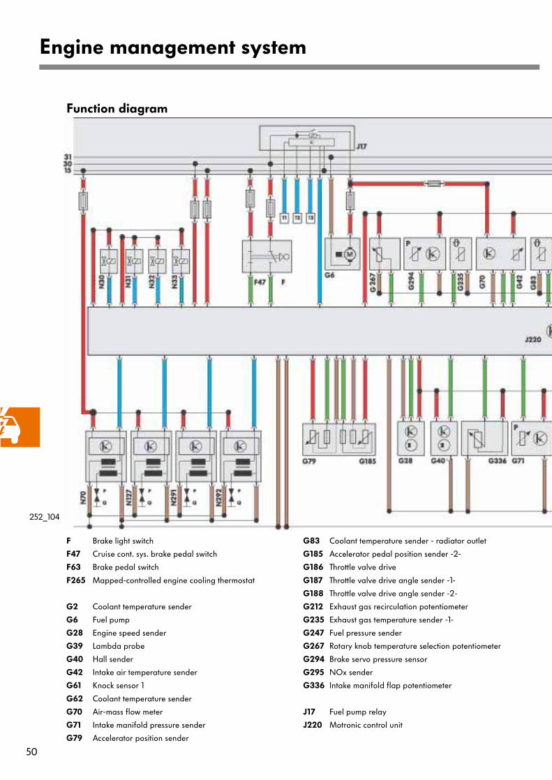
Function diagram
F Brake light switch
F47 Cruise cont. sys. brake pedal switch
F63 Brake pedal switch
F265 Mapped-controlled engine cooling thermostat
G2 Coolant temperature sender
G6 Fuel pump
G28 Engine speed sender
G39 Lambda probe
G40 Hall sender
G42 Intake air temperature sender
G61 Knock sensor 1
G62 Coolant temperature sender
G70 Air-mass flow meter
G71 Intake manifold pressure sender
G79 Accelerator position sender
G83 Coolant temperature sender - radiator outlet
G185 Accelerator pedal position sender -2-
G186 Throttle valve drive
G187 Throttle valve drive angle sender -1-
G188 Throttle valve drive angle sender -2-
G212 Exhaust gas recirculation potentiometer
G235 Exhaust gas temperature sender -1-
G247 Fuel pressure sender
G267 Rotary knob temperature selection potentiometer
G294 Brake servo pressure sensor
G295 NOx sender
G336 Intake manifold flap potentiometer
J17 Fuel pump relay
J220 Motronic control unit
252_104

51
Z19 Lambda probe heater
Z44 NOx sender heater
1 TD signal
2 K/W line
3 Air conditioner compressor
4 A/C ready
5 PWM signal from high pressure sender G65
6 CAN-Bus High
7 CAN-Bus Low
8 3-phase AC alternator terminal DFM
9 Fan control 1
10 Fan control 2
11 Line to terminal 50
12 Line to door contact switch
13 Line to airbag
J271 Motronic current supply relay
J338 Throttle valve control unit
J583 NOx sensor control unit
N70, N127,
N291,N292 Ignition coils 1 - 4 with output stages
N18 Exhaust gas recirculation valve
N30-33 Injectors 1 - 4
N80 Activated charcoal filter system solenoid valve 1
N205 Inlet camshaft timing adjustment valve -1-
N276 Fuel pressure regulating valve
N290 Fuel metering valve
N316 Intake manifold flap air flow control valve
P Spark plug socket
Q Spark plug
252_105
Positive terminal
Earth
Input signal
Output signal
Bidirectional line
CAN databus

52
Test your knowledge
1. The camshaft timing control results in ...
a) ... an improvement in engine smoothness.
b) ... optimum adjustment of internal exhaust gas recirculation with regard to emissions and fuel consumption
c) ... an improvement of the torque curve.
2. Why are the cylinder liners plasma-coated?
a) The plasma coating saves weight.
b) The plasma coating reduces the friction between the piston ring and the cylinder liner.
c) The plasma coating is more easily workable than the cylinder liner.
3. The specially shaped piston recess have the following purpose:
a) ... to save weight through material reduction.
b) ... to reduce combustion temperature through controlled mixture control.
c) ... to channel the fuel and the fresh air to the spark plug.
4. Which of the following statements regarding the stratified charge mode are true?
a) the fuel is channelled to the spark plug through the fuel recess of the piston and by the tumblingairflow.
b) the fuel is injected directly into the cylinder during the final third of the compression stroke.
c) At the point of ignition, an inner layer comprising an ignitable mixture and an outer layercomprising air and recirculated exhaust gases has formed inside the combustion chamber.

53
5. Which of the following statements regarding homogeneous mode are true?
a) In homogeneous mode, the fuel mixes uniformly (homogeneously) with the intake airthroughout the combustion chamber.
b) Homogeneous mode is equivalent to the operating mode of an engine with an intake manifold injection system.
c) In homogeneous mode, the fuel is injected directly into the cylinder during the intake stroke.
6. What is the task of the intake manifold flap changeover mechanism?
a) The intake air tumbles into the cylinder through the actuated intake manifold flap..
b) Internal exhaust gas recirculation is controlled by the intake manifold flap.
c) When the intake manifold flap is actuated, the intake air flow rate increases.
7. What pressures prevail in the fuel system?
a) In the high-pressure fuel system, the pressure is increased to max. 2000 bar.
b) In the low pressure fuel system, the pressure during normal operation is 3 bar.
c) In the high-pressure fuel system, the pressure is between 50 and 100 bar.
8. What is regeneration mode?
a) In regeneration mode, the NOx storage catalytic converter is purged of nitrogen oxides or sulphur.
b) In regeneration mode, the engine management system changes over to stratified charge mode.
c) Regeneration mode is a fuel-saving lean operating mode.

54
Special tools
Special tools
Designation Tool Use
T 10094 Pulling-off tool
The pulling-off tool is used to pull out the single-spark ignition coil.
T 10109Holder
The holder is attached to the cylinder block to support the engine.
T 10110Fixing flange
The fixing flange is used to adjust and check the correct camshaft position when fitting the camshaft adjuster.
252_149
252_133
252_134
55
Solutions to questions on pages 52-53
1.) b,c
2.) a,b
3.) c
4.) a,b,c
5.) a,b,c
6.) a,c
7.) b,c
8.) a

For internal use only © VOLKSWAGEN AG, Wolfsburg
All rights reserved. Technical specifications subject to change without notice.
140.2810.71.20 Technical status: 4/01
❀ This paper is produced from
non-chlorine-bleached pulp.
252
Top Related