


Languages
Pages
Legal

1
HiRadMat Proposal HRMT-22:
Tungsten Powder Target Experiment
(A follow-up to the HRMT-10 ‘W-Thimble’ Experiment in 2012)
Chris Densham, Otto Caretta, Tristan Davenne, Mike Fitton, Peter Loveridge, Joe O’Dell(RAL)
Ilias Efthymiopoulos, Nikolaos Charitonidis(CERN)
2 HiRadMat Technical Review, July 2014
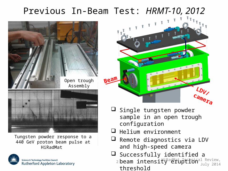
Previous In-Beam Test: HRMT-10, 2012
Beam
LDV/camera
Single tungsten powder sample in an open trough configuration
Helium environment Remote diagnostics via LDV and high-
speed camera Successfully identified a beam intensity
eruption threshold
Open trough Assembly
Tungsten powder response to a 440 GeV proton beam pulse at HiRadMat
3 HiRadMat Technical Review, July 2014
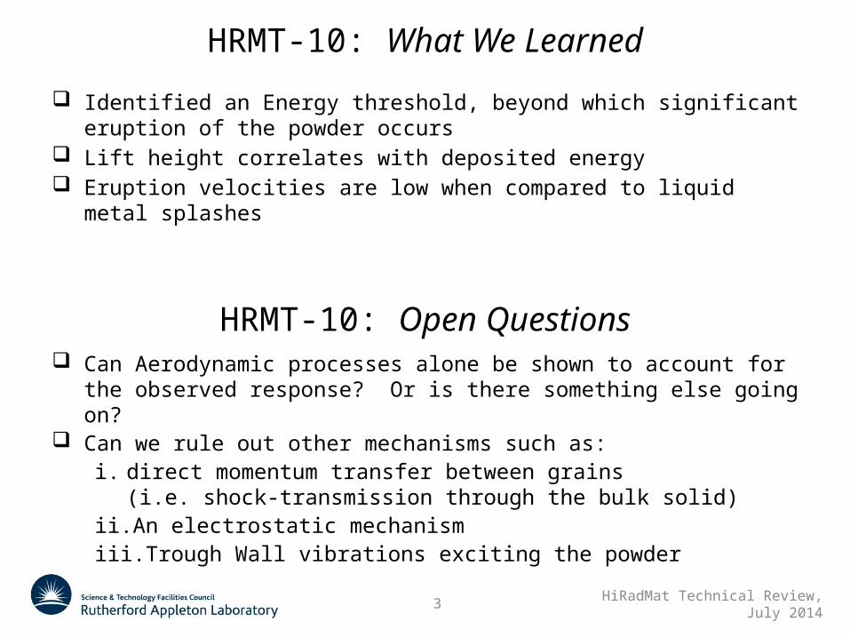
HRMT-10: What We Learned
Identified an Energy threshold, beyond which significant eruption of the powder occurs
Lift height correlates with deposited energy Eruption velocities are low when compared to liquid metal splashes
HRMT-10: Open Questions Can Aerodynamic processes alone be shown to account for the observed
response? Or is there something else going on? Can we rule out other mechanisms such as:
i. direct momentum transfer between grains (i.e. shock-transmission through the bulk solid)
ii. An electrostatic mechanismiii. Trough Wall vibrations exciting the powder
4 HiRadMat Technical Review, July 2014
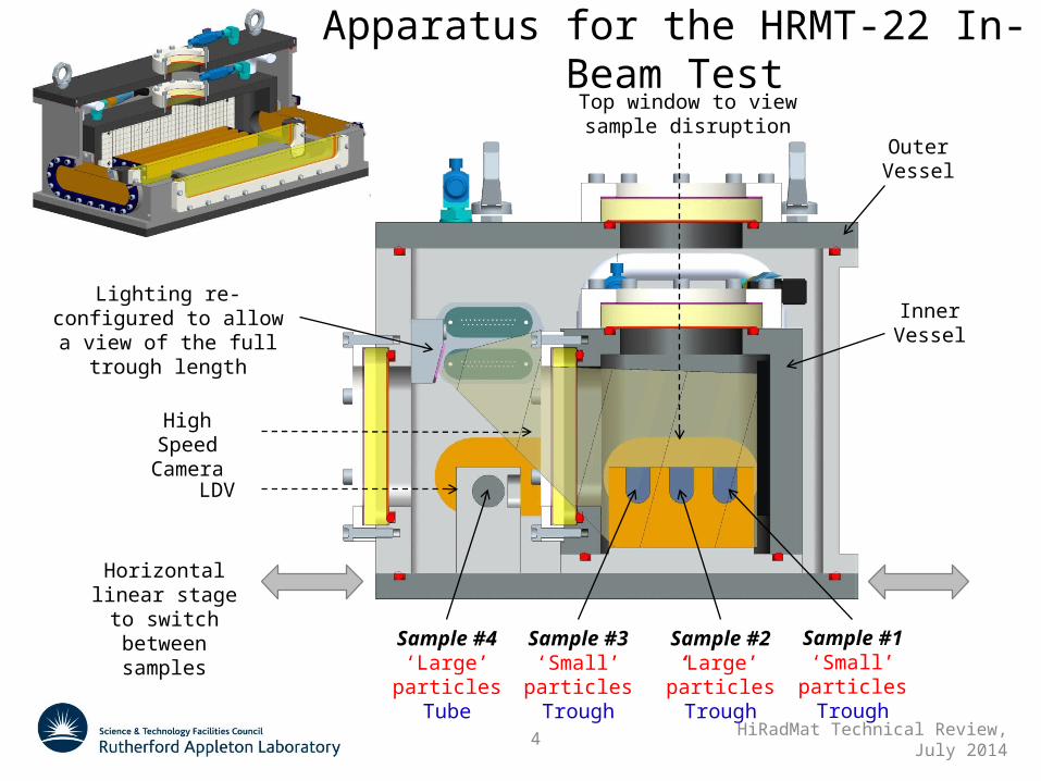
Apparatus for the HRMT-22 In-Beam TestTop window to view sample disruption
Lighting re-configured to allow a view of the full
trough length
Outer Vessel
Inner Vessel
High Speed Camera
LDV
Horizontal linear stage to switch
between samplesSample #1
‘Small’ particlesTrough
Sample #2‘Large’
particlesTrough
Sample #3‘Small’
particlesTrough
Sample #4‘Large’
particlesTube
5 HiRadMat Technical Review, July 2014
Key Improvements for a the HRMT-22 Experiment
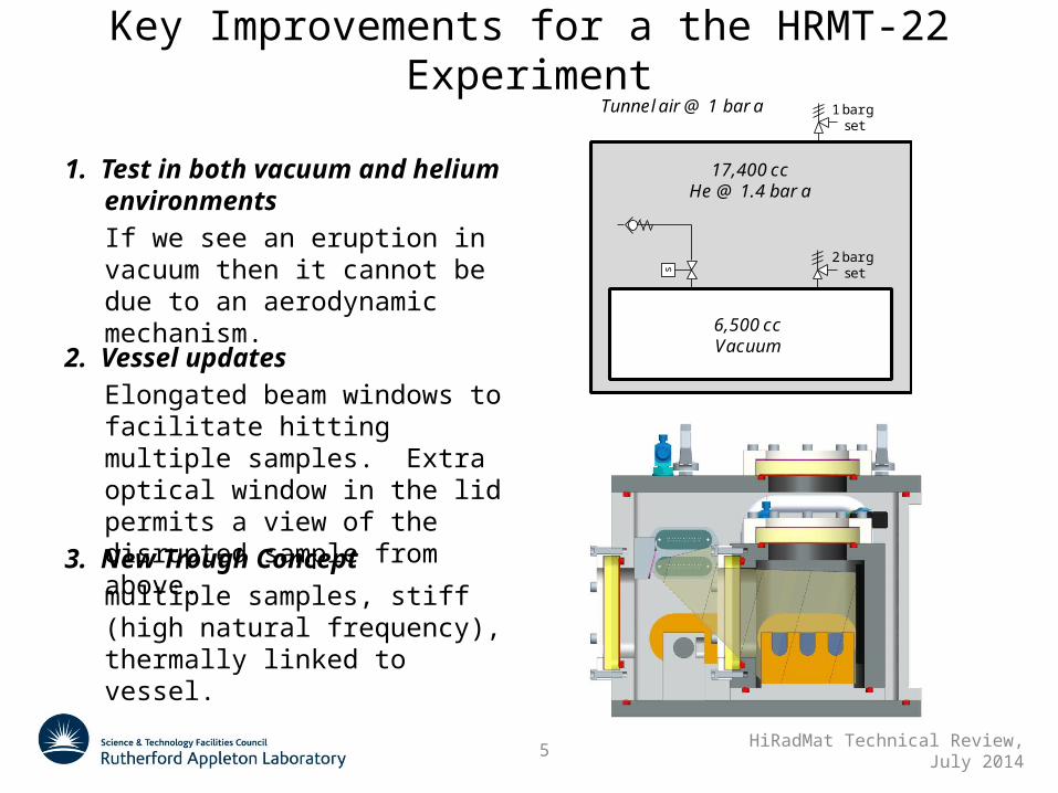
1. Test in both vacuum and helium environmentsIf we see an eruption in vacuum then it cannot be due to an aerodynamic mechanism.
s
2 bar gset
17,400 ccHe @ 1.4 bar a
6,500 ccVacuum
Tunnel air @ 1 bar a 1 bar gset
2. Vessel updatesElongated beam windows to facilitate hitting multiple samples. Extra optical window in the lid permits a view of the disrupted sample from above.
3. New Trough Conceptmultiple samples, stiff (high natural frequency), thermally linked to vessel.
6 HiRadMat Technical Review, July 2014
Key Improvements for a the HRMT-22 Experiment
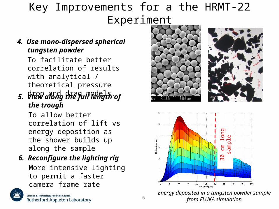
4. Use mono-dispersed spherical tungsten powderTo facilitate better correlation of results with analytical / theoretical pressure drop and drag models.
5. View along the full length of the troughTo allow better correlation of lift vs energy deposition as the shower builds up along the sample
Energy deposited in a tungsten powder samplefrom FLUKA simulation
30 c
m lo
ng s
ampl
e
6. Reconfigure the lighting rigMore intensive lighting to permit a faster camera frame rate
7 HiRadMat Technical Review, July 2014
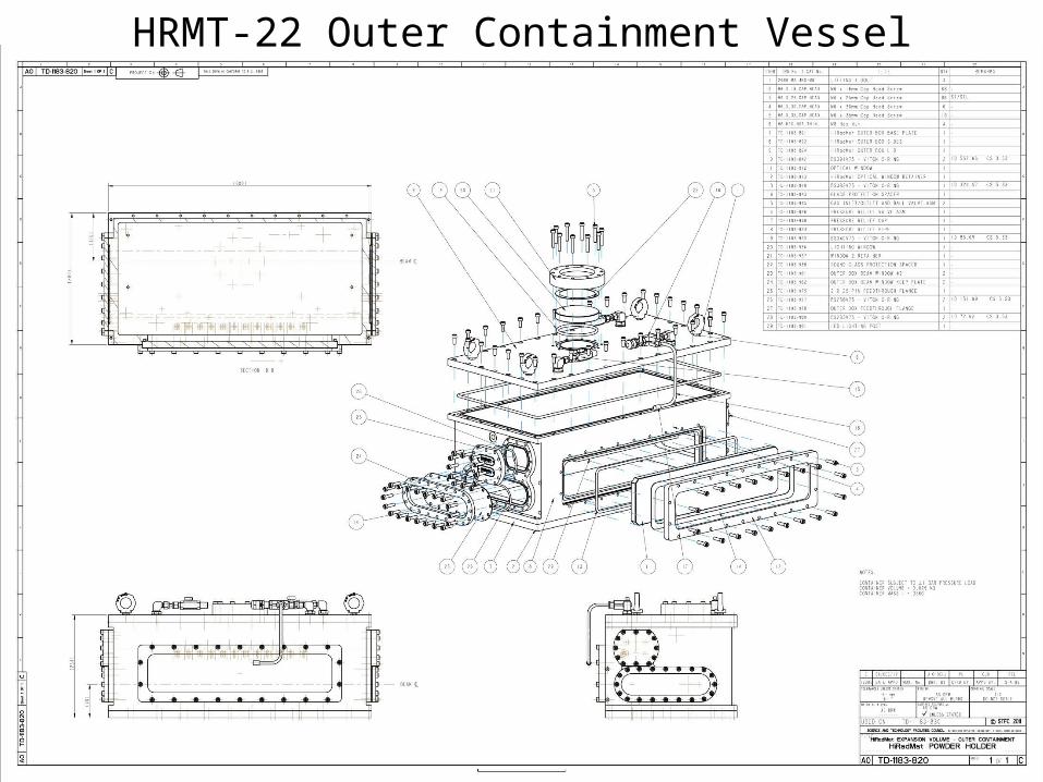
HRMT-22 Outer Containment Vessel
8 HiRadMat Technical Review, July 2014
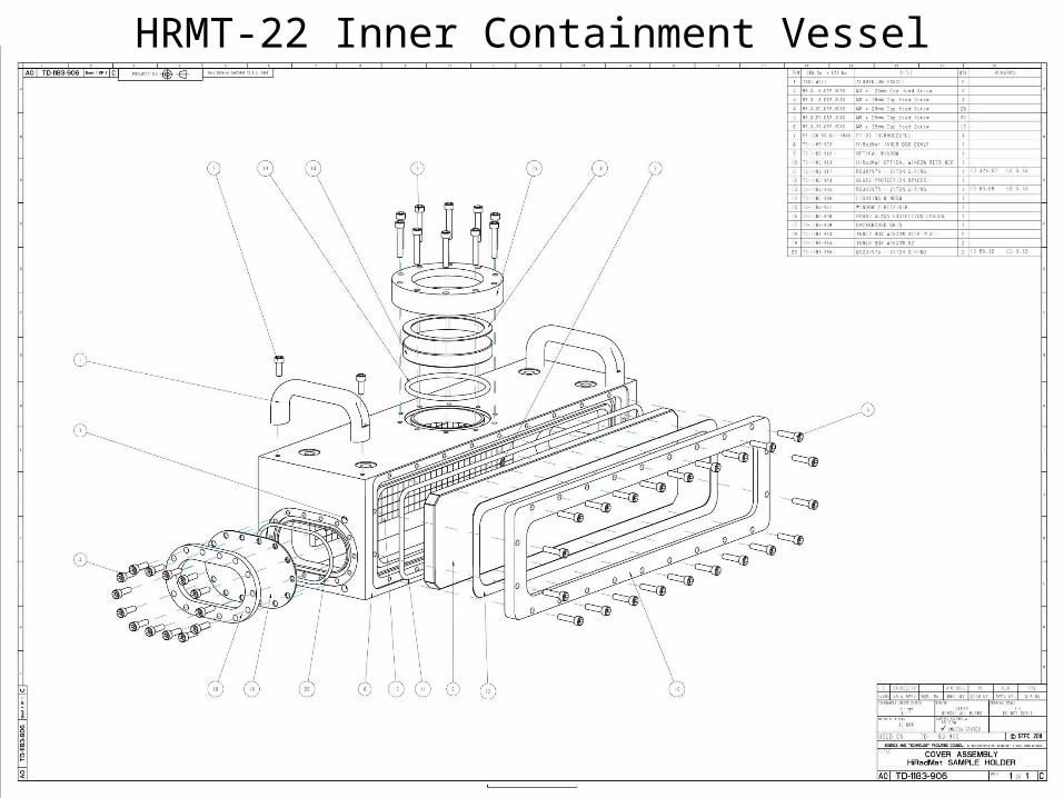
HRMT-22 Inner Containment Vessel
9 HiRadMat Technical Review, July 2014
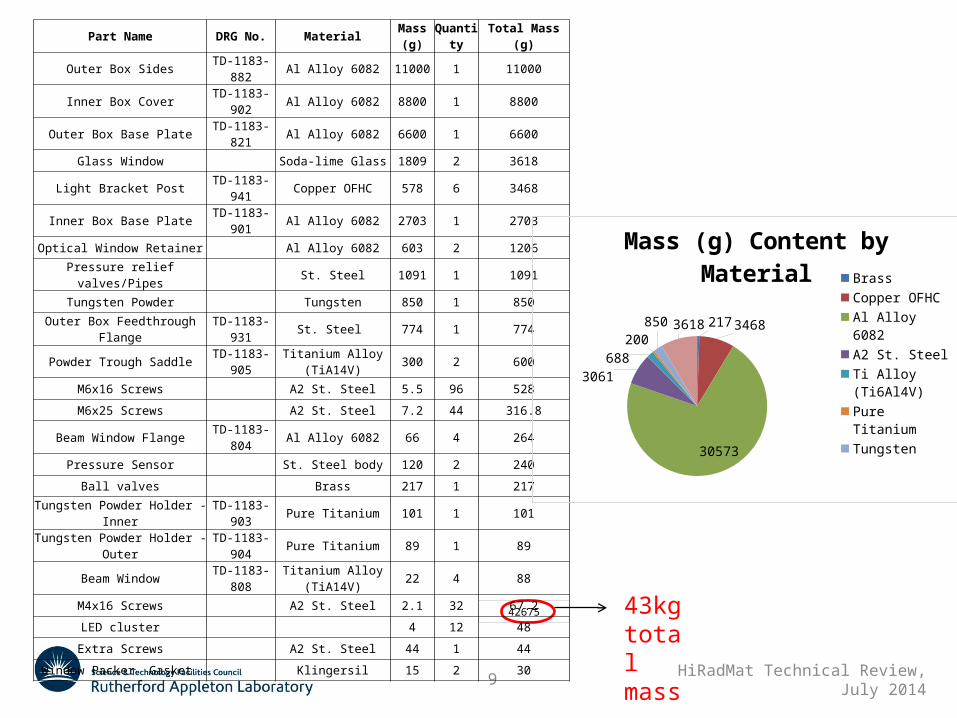
Part Name DRG No. Material Mass (g)Quantity Total Mass (g)
Outer Box Sides TD-1183-882 Al Alloy 6082 11000 1 11000
Inner Box Cover TD-1183-902 Al Alloy 6082 8800 1 8800
Outer Box Base Plate TD-1183-821 Al Alloy 6082 6600 1 6600
Glass Window Soda-lime Glass 1809 2 3618
Light Bracket Post TD-1183-941 Copper OFHC 578 6 3468
Inner Box Base Plate TD-1183-901 Al Alloy 6082 2703 1 2703
Optical Window Retainer Al Alloy 6082 603 2 1206
Pressure relief valves/Pipes St. Steel 1091 1 1091
Tungsten Powder Tungsten 850 1 850
Outer Box Feedthrough Flange TD-1183-931 St. Steel 774 1 774
Powder Trough Saddle TD-1183-905 Titanium Alloy (TiA14V) 300 2 600
M6x16 Screws A2 St. Steel 5.5 96 528
M6x25 Screws A2 St. Steel 7.2 44 316.8
Beam Window Flange TD-1183-804 Al Alloy 6082 66 4 264
Pressure Sensor St. Steel body 120 2 240
Ball valves Brass 217 1 217
Tungsten Powder Holder - Inner TD-1183-903 Pure Titanium 101 1 101
Tungsten Powder Holder - Outer TD-1183-904 Pure Titanium 89 1 89
Beam Window TD-1183-808 Titanium Alloy (TiA14V) 22 4 88
M4x16 Screws A2 St. Steel 2.1 32 67.2
LED cluster 4 12 48
Extra Screws A2 St. Steel 44 1 44
Window Packer Gasket Klingersil 15 2 30
42675
217
3468
30573
3061
688200
850
3618
Mass (g) Content by Material
Brass
Copper OFHC
Al Alloy 6082
A2 St. Steel
Ti Alloy (Ti6Al4V)
Pure Titanium
Tungsten
Glass
43kg total mass
10 HiRadMat Technical Review, July 2014
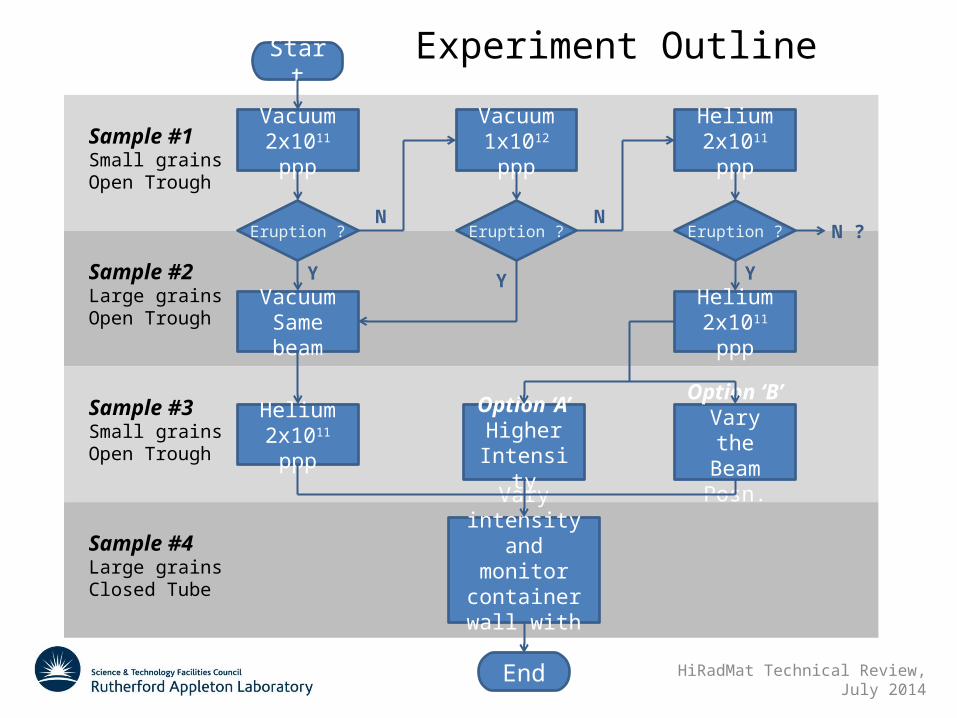
Experiment Outline
Sample #1Small grainsOpen Trough
Vacuum2x1011 ppp
Eruption ?
VacuumSame beam
Vacuum1x1012 ppp
Helium2x1011 ppp
Y
NEruption ?
Y
NEruption ?
Helium2x1011 ppp
Y
N ?
Option ‘A’Higher
Intensity
Option ‘B’Vary the
Beam Posn.
Helium2x1011 ppp
Vary intensity and monitor
container wall with LDV
Sample #2Large grainsOpen Trough
Sample #3Small grainsOpen Trough
Sample #4Large grainsClosed Tube
Start
End

11 HiRadMat Technical Review, July 2014
Preliminary Pulse List
HRMT-22 Beam Pulse ListCreated:
DRAFT 04-July-2014
Beam Pulse List
NoIntensity Beam spot [mm] Bunch
spacing [ns]Pulse length
[us]# bunches p/bunch Total Sigma_x Sigma_y1 5.00E+10 2.0 2.0 2 2.00E+11 2.0 2.0 3 2.00E+11 2.0 2.0 4 1.00E+12 2.0 2.0 5 5.00E+10 2.0 2.0 6 2.00E+11 2.0 2.0 7 2.00E+11 2.0 2.0 8 1.00E+12 2.0 2.0 9 5.00E+10 2.0 2.0
10 2.00E+11 2.0 2.0 11 2.00E+11 2.0 2.0 12 1.00E+12 2.0 2.0 13 5.00E+10 2.0 2.0 14 2.00E+11 2.0 2.0 15 2.00E+11 2.0 2.0 16 1.00E+12 2.0 2.0
Total 5.80E+12 Allow for a total budget of up to 1e13 protons (a few extra shots?)
12 HiRadMat Technical Review, July 2014
Obs
erve
d Er
uptio
ns
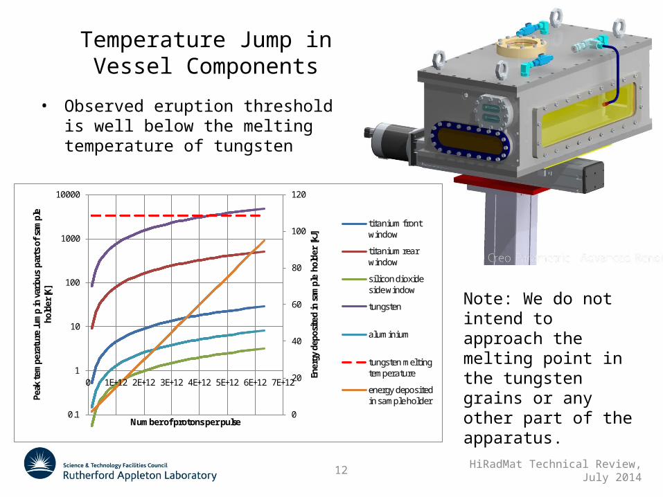
• Observed eruption threshold is well below the melting temperature of tungsten
Temperature Jump in Vessel Components
Note: We do not intend to approach the melting point in the tungsten grains or any other part of the apparatus.
0
20
40
60
80
100
120
0.1
1
10
100
1000
10000
0 1E+12 2E+12 3E+12 4E+12 5E+12 6E+12 7E+12
Ener
gy d
epos
ited
in s
ampl
e ho
lder
[kJ
]
Peak
tem
pera
ture
Jum
p in
var
ious
par
ts o
f sa
mpl
e ho
lder
[K]
Number of protons per pulse
titanium front window
titanium rear window
sil icon dioxide side window
tungsten
aluminium
tungsten melting temperature
energy deposited in sample holder
13 HiRadMat Technical Review, July 2014
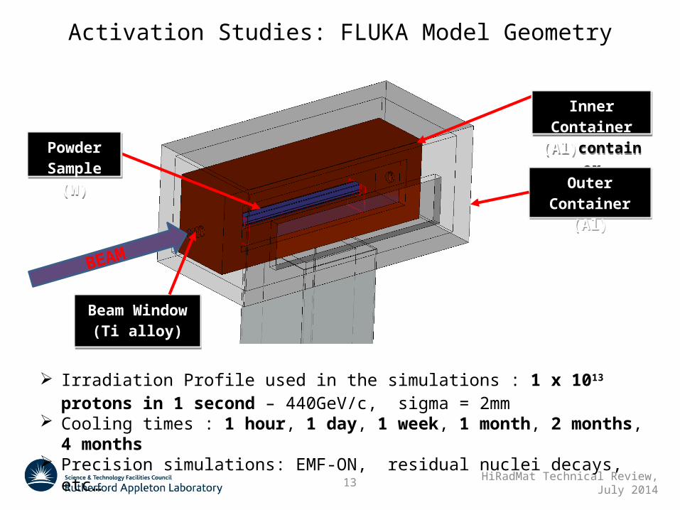
Activation Studies: FLUKA Model Geometry
Inner Container (Al)container
Inner Container (Al)container
Outer Container (Al)
Outer Container (Al)
Powder Sample (W)
Powder Sample (W)
Beam Window (Ti alloy)
Beam Window (Ti alloy)
BEAM
Irradiation Profile used in the simulations : 1 x 10¹³ protons in 1 second –
440GeV/c, sigma = 2mm Cooling times : 1 hour, 1 day, 1 week, 1 month, 2 months, 4 months Precision simulations: EMF-ON, residual nuclei decays, etc…
14 HiRadMat Technical Review, July 2014
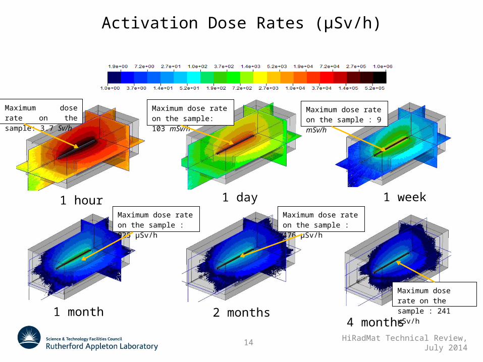
Activation Dose Rates (μSv/h)
1 hour 1 day 1 week
1 month 2 months4 months
Maximum dose rate on the sample: 3.7 Sv/h
Maximum dose rate on the sample: 103 mSv/h
Maximum dose rate on the sample : 9 mSv/h
Maximum dose rate on the sample : 925 μSv/h
Maximum dose rate on the sample : 476 μSv/h
Maximum dose rate on the sample : 241 μSv/h
15 HiRadMat Technical Review, July 2014
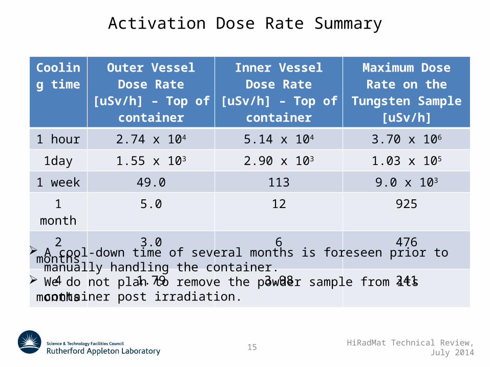
Activation Dose Rate Summary
Cooling time
Outer VesselDose Rate [uSv/h] –
Top of container
Inner VesselDose Rate [uSv/h] –
Top of container
Maximum Dose Rate on the Tungsten Sample [uSv/h]
1 hour 2.74 x 10⁴ 5.14 x 10⁴ 3.70 x 10⁶
1day 1.55 x 10³ 2.90 x 10³ 1.03 x 10⁵
1 week 49.0 113 9.0 x 10³
1 month 5.0 12 925
2 months 3.0 6 476
4 months 1.79 3.98 241
A cool-down time of several months is foreseen prior to manually handling the container.
We do not plan to remove the powder sample from its container post irradiation.
16 HiRadMat Technical Review, July 2014
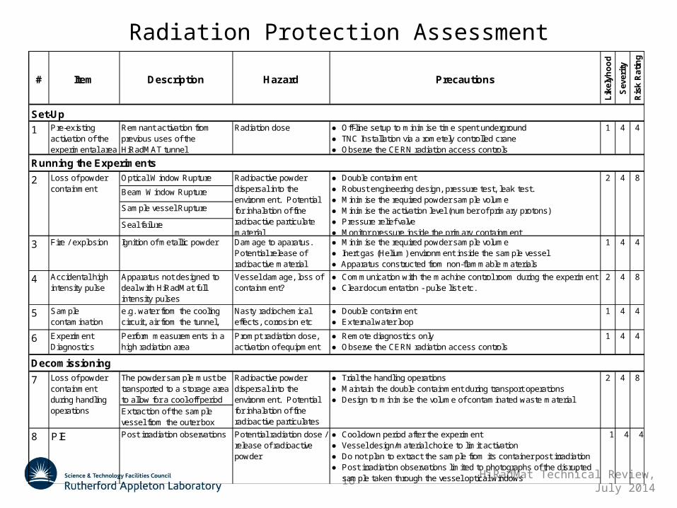
Radiation Protection Assessment
# Item Description Hazard Precautions
Lik
elyh
oo
d
Sev
erit
y
Ris
k R
atin
g
1 Pre-existing activation of the experimental area
Remnant activation from previous uses of the HiRadMAT tunnel
Radiation dose ● Off-line setup to minimise time spent underground● TNC Installation via a rometely controlled crane● Observe the CERN radiation access controls
1 4 4
Optical Window Rupture
Beam Window Rupture
Sample vessel Rupture
Seal failure
3 Fire / explosion Ignition of metallic powder Damage to aparatus. Potential release of radioactive material
● Minimise the required powder sample volume● Inert gas (Helium) environment inside the sample vessel● Apparatus constructed from non-flammable materials
1 4 4
4 Accidental high intensity pulse
Apparatus not designed to deal with HiRadMat full intensity pulses
Vessel damage, loss of containment?
● Communication with the machine control room during the experiment● Clear documentation - pulse list etc.
2 4 8
5 Sample contamination
e.g. water from the cooling circuit, air from the tunnel, etc
Nasty radiochemical effects, corrosion etc
● Double containment● External water loop
1 4 4
6 Experiment Diagnostics
Perform measurements in a high radiation area
Prompt radiation dose, activation of equipment
● Remote diagnostics only● Observe the CERN radiation access controls
1 4 4
The powder sample must be transported to a storage area to allow for a cool-off periodExtraction of the sample vessel from the outer box
8 PIE Post irradiation observations Potential radiation dose / release of radioactive powder
● Cool-down period after the experiment● Vessel design/material choice to limit activation● Do not plan to extract the sample from its container post irradiation● Post irradiation observations limited to photographs of the disrupted sample taken through the vessel optical windows
1 4 4
Loss of powder containment
Radioactive powder dispersal into the environment. Potential for inhalation of fine radioactive particulate material
8
Set-Up
Running the Experiments
Decomissioning
7
● Double containment● Robust engineering design, pressure test, leak test.● Minimise the required powder sample volume● Minimise the activation level (number of primary protons)● Pressure relief valve● Monitor pressure inside the primary containment
2 4 82
Loss of powder containment during handling operations
Radioactive powder dispersal into the environment. Potential for inhalation of fine radioactive particulates
● Trial the handling operations● Maintain the double containment during transport operations● Design to minimise the volume of contaminated waste material
2 4
17 HiRadMat Technical Review, July 2014
# Item Description Hazard Precautions
Lik
elyh
oo
d
Sev
erit
y
Ris
k R
atin
g
1 Pre-existing activation of the experimental area
Remnant activation from previous uses of the HiRadMAT tunnel
Radiation dose ● Off-line setup to minimise time spent underground● TNC Installation via a rometely controlled crane● Observe the CERN radiation access controls
1 4 4
Optical Window Rupture
Beam Window Rupture
Sample vessel Rupture
Seal failure
3 Fire / explosion Ignition of metallic powder Damage to aparatus. Potential release of radioactive material
● Minimise the required powder sample volume● Inert gas (Helium) environment inside the sample vessel● Apparatus constructed from non-flammable materials
1 4 4
4 Accidental high intensity pulse
Apparatus not designed to deal with HiRadMat full intensity pulses
Vessel damage, loss of containment?
● Communication with the machine control room during the experiment● Clear documentation - pulse list etc.
2 4 8
5 Sample contamination
e.g. water from the cooling circuit, air from the tunnel, etc
Nasty radiochemical effects, corrosion etc
● Double containment● External water loop
1 4 4
6 Experiment Diagnostics
Perform measurements in a high radiation area
Prompt radiation dose, activation of equipment
● Remote diagnostics only● Observe the CERN radiation access controls
1 4 4
The powder sample must be transported to a storage area to allow for a cool-off periodExtraction of the sample vessel from the outer box
8 PIE Post irradiation observations Potential radiation dose / release of radioactive powder
● Cool-down period after the experiment● Vessel design/material choice to limit activation● Do not plan to extract the sample from its container post irradiation● Post irradiation observations limited to photographs of the disrupted sample taken through the vessel optical windows
1 4 4
Loss of powder containment
Radioactive powder dispersal into the environment. Potential for inhalation of fine radioactive particulate material
8
Set-Up
Running the Experiments
Decomissioning
7
● Double containment● Robust engineering design, pressure test, leak test.● Minimise the required powder sample volume● Minimise the activation level (number of primary protons)● Pressure relief valve● Monitor pressure inside the primary containment
2 4 82
Loss of powder containment during handling operations
Radioactive powder dispersal into the environment. Potential for inhalation of fine radioactive particulates
● Trial the handling operations● Maintain the double containment during transport operations● Design to minimise the volume of contaminated waste material
2 4
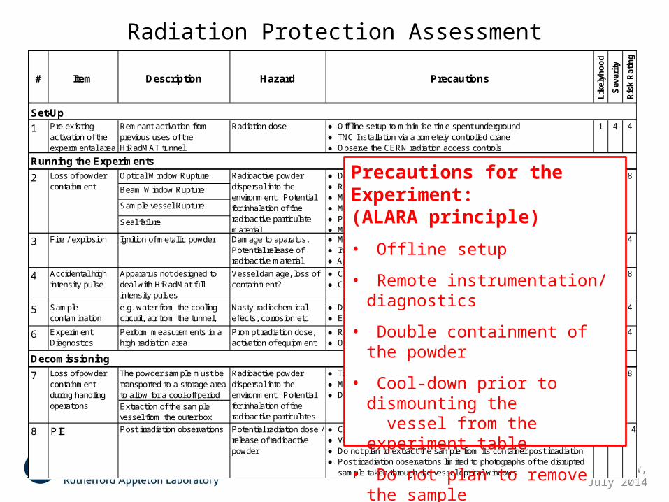
Radiation Protection Assessment
Precautions for the Experiment:(ALARA principle)
• Offline setup
• Remote instrumentation/ diagnostics
• Double containment of the powder
• Cool-down prior to dismounting the vessel from the experiment table
• Do not plan to remove the sample from its container for post irradiation measurements
18 HiRadMat Technical Review, July 2014
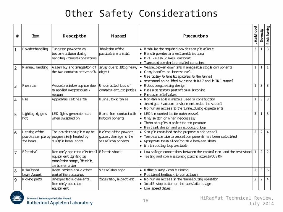
Other Safety Considerations
# Item Description Hazard Precautions
Lik
elyh
oo
d
Sev
erit
y
Ris
k R
atin
g
1 Powder handling Tungsten powder may become airborn during handling / transfer operations
Inhalation of fine particulate material
● Minimise the required powder sample volume● Handle powder in a well ventilated area● PPE - mask, gloves, overcoat● Transport powder in a sealed container
3 1 3
2 Manual Handling Assembly and integration of the two containment vessels
Injury due to lifting heavy object
● Vessel broken down into manageable single components● Carry handles on inner vessel● Use trolley to tansfer aparatus to the tunnel● test stand an be lifted by crane in BA7 and in TNC tunnel
1 1 1
3 Pressure Vessel / window rupture due to applied overpressure / vacuum
Uncontrolled loss of containment, projectiles
● Robust engineering design● Pressure test as part of commissioning● Pressure relief valves
1 3 3
4 Fire Apparatus catches fire Burns, toxic fumes ● Non-flammable materials used in construction● innert gas / vacuum environment inside the vessel● No human access to the tunnel during experiments
1 3 3
5 Lighting rig gets hot
LED lights generate heat when switched on
Burns from contact with hot components
● LED's mounted inside outer vessel● Only switch on when neccessary● Thermocouples monitor the temperature● Heat sink design and water cooling loop
3 1 3
6 Heating of the powder sample by the beam
The powder sample may be progressively heated by multiple beam shots
Melting of the powder grains, damage to the vessel components
● Sample contained inside purpose made vessel● Temperature rise in vessel components has been calculated● Apropriate thermal cooling time between shots● Water cooling loop available
2 2 4
7 Electrical Remotely operated electrical equipment: lighting rig, translation stage, lift table, instrumentation
Electric shock ● Low voltage connections between the control room and the test stand● Testing and commissioning prior to arrival at CERN
1 2 2
8 Misaligned beam/target
Beam strikes some other part of the apparatus
Vessel damaged ● Offline survey / comissioning● Positional feedback to control room
2 3 6
9 Moving parts Unexpected movements. Remotely operated equipment.
finger trap, impact, etc. ● No human access in the tunnel during operation● local E-stop button on the translation stage● Low speed drives
2 2 4
19 HiRadMat Technical Review, July 2014
# Item Description Hazard Precautions
Lik
elyh
oo
d
Sev
erit
y
Ris
k R
atin
g
1 Powder handling Tungsten powder may become airborn during handling / transfer operations
Inhalation of fine particulate material
● Minimise the required powder sample volume● Handle powder in a well ventilated area● PPE - mask, gloves, overcoat● Transport powder in a sealed container
3 1 3
2 Manual Handling Assembly and integration of the two containment vessels
Injury due to lifting heavy object
● Vessel broken down into manageable single components● Carry handles on inner vessel● Use trolley to tansfer aparatus to the tunnel● test stand an be lifted by crane in BA7 and in TNC tunnel
1 1 1
3 Pressure Vessel / window rupture due to applied overpressure / vacuum
Uncontrolled loss of containment, projectiles
● Robust engineering design● Pressure test as part of commissioning● Pressure relief valves
1 3 3
4 Fire Apparatus catches fire Burns, toxic fumes ● Non-flammable materials used in construction● innert gas / vacuum environment inside the vessel● No human access to the tunnel during experiments
1 3 3
5 Lighting rig gets hot
LED lights generate heat when switched on
Burns from contact with hot components
● LED's mounted inside outer vessel● Only switch on when neccessary● Thermocouples monitor the temperature● Heat sink design and water cooling loop
3 1 3
6 Heating of the powder sample by the beam
The powder sample may be progressively heated by multiple beam shots
Melting of the powder grains, damage to the vessel components
● Sample contained inside purpose made vessel● Temperature rise in vessel components has been calculated● Apropriate thermal cooling time between shots● Water cooling loop available
2 2 4
7 Electrical Remotely operated electrical equipment: lighting rig, translation stage, lift table, instrumentation
Electric shock ● Low voltage connections between the control room and the test stand● Testing and commissioning prior to arrival at CERN
1 2 2
8 Misaligned beam/target
Beam strikes some other part of the apparatus
Vessel damaged ● Offline survey / comissioning● Positional feedback to control room
2 3 6
9 Moving parts Unexpected movements. Remotely operated equipment.
finger trap, impact, etc. ● No human access in the tunnel during operation● local E-stop button on the translation stage● Low speed drives
2 2 4
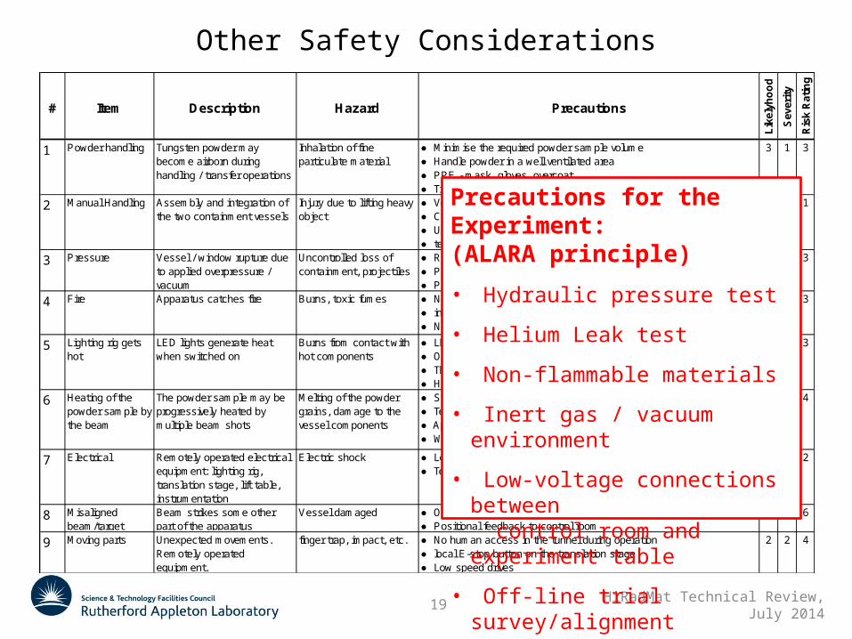
Other Safety Considerations
Precautions for the Experiment:(ALARA principle)
• Hydraulic pressure test
• Helium Leak test
• Non-flammable materials
• Inert gas / vacuum environment
• Low-voltage connections between control room and experiment table
• Off-line trial survey/alignment
20 HiRadMat Technical Review, July 2014
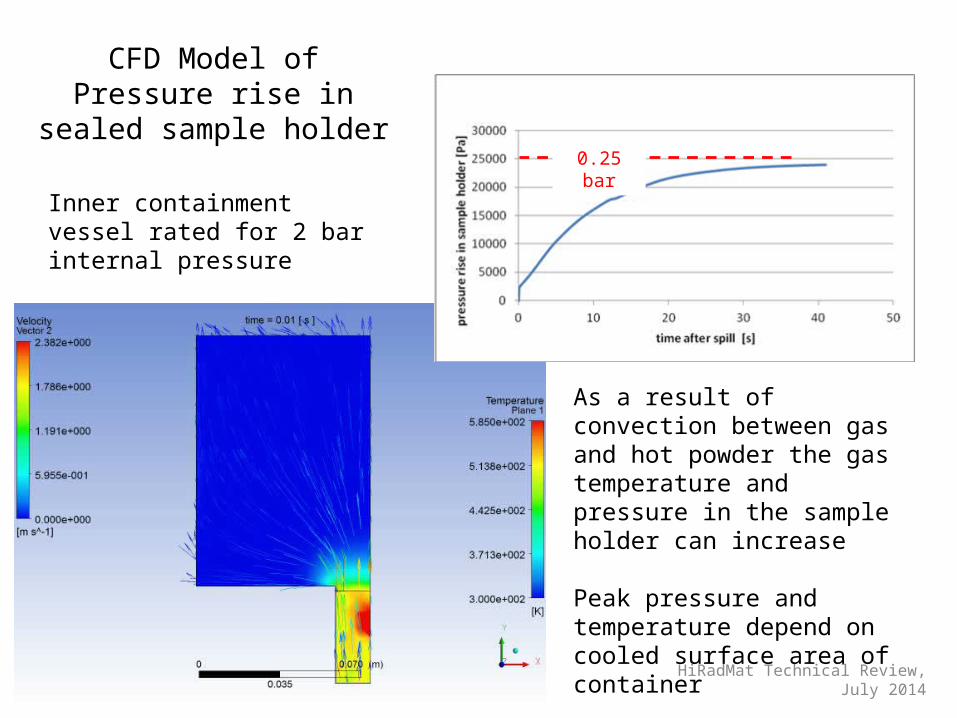
CFD Model of Pressure rise in sealed sample holder
As a result of convection between gas and hot powder the gas temperature and pressure in the sample holder can increase
Peak pressure and temperature depend on cooled surface area of container
Inner containment vessel rated for 2 bar internal pressure
0.25 bar
21 HiRadMat Technical Review, July 2014
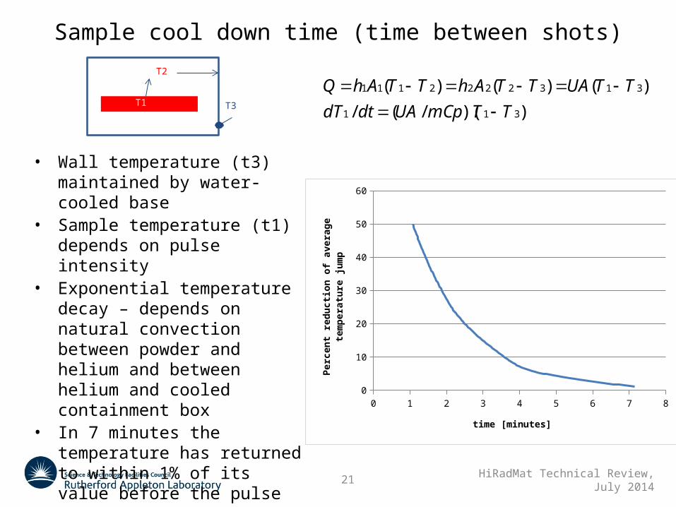
Sample cool down time (time between shots)
0 1 2 3 4 5 6 7 80
10
20
30
40
50
60
time [minutes]
Perc
ent r
educ
tion
of a
vera
ge te
mpe
ratu
re ju
mp
))(/(/
)()()(
311
3132222111
TTmCpUAdtdT
TTUATTAhTTAhQ
T3T1
T2
• Wall temperature (t3) maintained by water-cooled base
• Sample temperature (t1) depends on pulse intensity
• Exponential temperature decay – depends on natural convection between powder and helium and between helium and cooled containment box
• In 7 minutes the temperature has returned to within 1% of its value before the pulse
22 HiRadMat Technical Review, July 2014
Summary
In 2012 the HRMT-10 experiment we observed beam-induced eruptions in a tungsten powder target. A new experimental cell has been designed for the follow-up HRMT-22 experiment.
The rig incorporates the successful safety and containment features implemented with the first experiment: Double containment Remote diagnostics Offline setup
The improvements in the design include: The possibility to house multiple independent samples The possibility to test in vacuum and helium environments Wider camera field of view More intense lighting (higher camera frame rate?) Mono-dispersed spherical powder
Top Related