


![SINTRA REAL 1889-1910revistatritao.cm-sintra.pt/images/galeria/sintrareal/Sintra-Real.pdf · Palácio Real da Pena em Sintra. S. l. [Sintra], s. d. [06 de Setembro de 1899]. Fotógrafo:](https://static.fdocuments.net/doc/165x107/5fd9a8adce30c176d93da239/sintra-real-1889-palcio-real-da-pena-em-sintra-s-l-sintra-s-d-06-de.jpg)


Languages
Pages
Legal


cop2
AIRDISTRIBUTIONPERFORATEDMETALLIC DUCTS WITH ANOPEN CIRCUMFERENCESELECTION CATALOGUE
SISTEMI INNOVATIVI TRATTAMENTO ARIA AMBIENTE
02_Spiropack_ing_v8 ok_Layout 1 24/10/12 17.51 Pagina cop2

JULY 2012 EDITION
02_Spiropack_ing_v8 ok_Layout 1 24/10/12 17.51 Pagina 1

METALLIC DUCTS:
DIMENSIONS AND MATERIAL
The metallic ducts with SPIROPACK™ technology are built in pieces
with a length of 1m with 8mm flanges at each end. These flanges
are made to couple the pieces together, which will be then united with
an omega collar.
The available versions are:
• Zn high quality galvanized steel SG250
• Ep painted with high resistancy epoxy powders
(ral color on demand)
• Inox/s 430 satinized stainless steel AISI 430
• Inox/L 430 polished stainless steel AISI 430
All pieces are supplied with a protective polyethylene film, which
must be removed within 10 days from the delivery of the ducts.
Upon request, it is possible to also have the following materials:
• Inox /s 304 satinized stainless steel AISI 304
• Inox /s 316L satinized stainless steel AISI 316L
• Cu Copper
• All Aluminium
The data quoted above are indicative and are not binding.
SINTRA reserves itself the right to modify them at any time, with no obligation of advanced notification
ny use or reproduction af any part of this docum
ent in any w
ay, all the filling or databases or other system
s are not allow
ed w
othout previous w
ritten confirm
ation by S
IN
TR
A.
2
DIAMETER
02_Spiropack_ing_v8 ok_Layout 1 24/10/12 17.51 Pagina 2

PATENTED GREEN TECHNOLOGY
SPIROPACK™
The data quoted above are indicative and are not binding.
SINTRA reserves itself the right to modify them at any time, with no obligation of advanced notification
ny use or reproduction af any part of this docum
ent in any w
ay, all the filling or databases or other system
s are not allow
ed w
othout previous w
ritten confirm
ation by S
IN
TR
A.
3
SINTRA’s ducts are produced with the patented SPIROPACK™ green technology. This technique consists in producing the ducts with an
open circumference, with a set warpage of the diameter, which allows:
• reduction of the transportation costs
• reduction of the packing costs
• easiness to assembly on site
• reduction of the assembly costs and times
• easy to inspect
• protection of the external surface with film
This SPIROPACK™ technology, despite the riveting which has to be done on site, allows great savings on the assembling times due to a
better management of the encumbrances and to an easy way to find the pieces.
02_Spiropack_ing_v8 ok_Layout 1 24/10/12 17.51 Pagina 3

GALVANIZED STEEL INOX ALUMINIUM COPPER
THICKNESS THICKNESS THICKNESS THICKNESS
Ø EXPANSION 8/10 10/10 12/10 15/10 8/10 10/10 12/10 10/10 10/10
mm mm Kg Kg Kg Kg Kg Kg Kg Kg Kg
280 879 5,7 7,0 8,8 11,4 5,7 7,0 8,8 2,4 6,3
300 942 6,1 7,5 9,4 11,3 6,1 7,5 9,4 2,5 6,8
315 989 6,4 7,9 9,9 11,9 6,4 7,9 9,9 2,7 7,1
350 1.099 7,1 8,8 11,0 13,2 7,1 8,8 11,0 3,0 7,9
355 1.115 7,2 8,9 11,1 13,4 7,2 8,9 11,1 3,0 8,0
400 1.256 8,2 10,0 12,6 15,1 8,2 10,0 12,6 3,4 9,0
450 1.413 9,2 11,3 14,1 17,0 9,2 11,3 14,1 3,8 10,2
500 1.570 10,2 12,6 15,7 18,8 10,2 12,6 15,7 4,2 11,3
550 1.727 11,2 13,8 17,3 20,7 11,2 13,8 17,3 4,7 12,4
560 1.758 11,4 14,1 17,6 21,1 11,4 14,1 17,6 4,7 12,7
600 1.884 12,2 15,1 18,8 22,6 12,2 15,1 18,8 5,1 13,6
630 1.978 12,9 15,8 19,8 23,7 12,9 15,8 19,8 5,3 14,2
650 2.041 13,3 16,3 20,4 24,5 13,3 16,3 20,4 5,5 14,7
700 2.198 14,3 17,6 22,0 26,4 14,3 17,6 22,0 5,9 15,8
710 2.229 14,5 17,8 22,3 26,8 14,5 17,8 22,3 6,0 16,1
750 2.355 15,3 18,8 23,6 28,3 15,3 18,8 23,6 6,4 17,0
800 2.512 16,3 20,1 25,1 30,1 16,3 20,1 25,1 6,8 18,1
850 2.669 17,3 21,4 26,7 32,0 17,3 21,4 26,7 7,2 19,2
900 2.826 18,4 22,6 28,3 33,9 18,4 22,6 28,3 7,6 20,3
950 2.983 19,4 23,9 29,8 35,8 19,4 23,9 29,8 8,1 21,5
1.000 3.140 20,4 25,1 31,4 37,7 20,4 25,1 31,4 8,5 22,6
1.050 3.297 21,4 26,4 33,0 39,6 21,4 26,4 33,0 8,9 23,7
1.100 3.454 22,5 27,6 34,5 41,4 22,5 27,6 34,5 9,3 24,9
1.150 3.611 23,5 28,9 36,1 43,3 23,5 28,9 36,1 9,7 26,0
1.200 3.768 24,5 30,1 37,7 45,2 24,5 30,1 37,7 10,2 27,1
1.250 3.925 25,5 31,4 39,3 47,1 25,5 31,4 39,3 10,6 28,3
1.300 4.082 26,5 32,7 40,8 49,0 26,5 32,7 40,8 11,0 29,4
1.350 4.239 27,6 33,9 42,4 50,9 27,6 33,9 42,4 11,4 30,5
1.400 4.396 28,6 35,2 44,0 52,8 28,6 35,2 44,0 11,9 31,7
1.450 4.553 29,6 36,4 45,5 54,6 29,6 36,4 45,5 12,3 32,8
1.500 4.710 30,6 37,7 47,1 56,5 30,6 37,7 47,1 12,7 33,9
1.550 4.867 31,6 38,9 48,7 58,4 31,6 38,9 48,7 13,1 35,0
1.600 5.024 32,7 40,2 50,2 60,3 32,7 40,2 50,2 13,6 36,2
WEIGHTS AND EXPANSION
CHART
The data quoted above are indicative and are not binding.
SINTRA reserves itself the right to modify them at any time, with no obligation of advanced notification
ny use or reproduction af any part of this docum
ent in any w
ay, all the filling or databases or other system
s are not allow
ed w
othout previous w
ritten confirm
ation by S
IN
TR
A.
4
Suggested thickness
02_Spiropack_ing_v8 ok_Layout 1 24/10/12 17.51 Pagina 4

PRESSURE DROPS
The duct’s pressure drops are determined by
three factors:
• Pressure drops generated by the hole pun-
ching
• Pressure drops due to the air transportation
inside the duct itself
• Pressure drops due to the presence of
connection pieces such as bends, tape-
rings, etc.
Here following there is a graph of the linear
pressure drops distributed inside blind ducts
with a roughness of 0.1mm (“smooth” circular
ducts) and at 0m on the sea level.
Legend:
Q: air flow (m3/h/m)
Ø: duct’s diameter
V: air crossing speed
ΔP0: Pressure drop in Pa per linear meter
The data quoted above are indicative and are not binding.
SINTRA reserves itself the right to modify them at any time, with no obligation of advanced notification
ny use or reproduction af any part of this docum
ent in any w
ay, all the filling or databases or other system
s are not allow
ed w
othout previous w
ritten confirm
ation by S
IN
TR
A.
LINEAR DISTRIBUTED PRESSURE DROPS
5
Pressure drops distributed in blind ducts
02_Spiropack_ing_v8 ok_Layout 1 24/10/12 17.51 Pagina 5

PRESSURE DROPS
The data quoted above are indicative and are not binding.
SINTRA reserves itself the right to modify them at any time, with no obligation of advanced notification
ny use or reproduction af any part of this docum
ent in any w
ay, all the filling or databases or other system
s are not allow
ed w
othout previous w
ritten confirm
ation by S
IN
TR
A.
6
Legend:
Q: air flow (m3/h) at the tapering’s entrance
Ø: tapering’s initial and final diameter
V: air crossing speed
ΔP0: pressure drops concentrated in the tapering
PRESSURE DROPS CONCENTRATED IN THE TAPERINGS
ØA
ØB
02_Spiropack_ing_v8 ok_Layout 1 24/10/12 17.51 Pagina 6

PRESSURE DROPS
The data quoted above are indicative and are not binding.
SINTRA reserves itself the right to modify them at any time, with no obligation of advanced notification
ny use or reproduction af any part of this docum
ent in any w
ay, all the filling or databases or other system
s are not allow
ed w
othout previous w
ritten confirm
ation by S
IN
TR
A.
7
Legend:
Q: air flow (m3/h) at the bend’s entrance
Ø: bend’s initial and final diameter
V: air crossing speed
ΔP0: pressure drops concentrated in the bend
Ø
R
R = ø
PRESSURE DROPS CONCENTRATED IN 90° BENDS
02_Spiropack_ing_v8 ok_Layout 1 24/10/12 17.51 Pagina 7

8
PRESSURE DROPS
The data quoted above are indicative and are not binding.
SINTRA reserves itself the right to modify them at any time, with no obligation of advanced notification
ny use or reproduction af any part of this docum
ent in any w
ay, all the filling or databases or other system
s are not allow
ed w
othout previous w
ritten confirm
ation by S
IN
TR
A.
Legend:
V1 [m/s]: Air speed at the T’s entrance
V2 [m/s]: Air speed at the T’s exit
(opposed to the entrance)
V3 [m/s]: Air speed at the T’s exit
(90° opposed to the entrance)
Δp1 [Pa]: Pressure loss concentrated between
V1 and V3
Δp2 [Pa]: Pressure loss concentrated between
V1 and V2
PRESSURE DROPS CONCENTRATED IN THE T WITH A 90° BRANCH
V2V1
V3
90°
Concentrated pressure drop with regard to the axial exit
Concentrated pressure drop with regard to the 90° lateral exit
02_Spiropack_ing_v8 ok_Layout 1 24/10/12 17.51 Pagina 8
9
PRESSURE DROPS
The data quoted above are indicative and are not binding.
SINTRA reserves itself the right to modify them at any time, with no obligation of advanced notification
V2V1
V3
60°
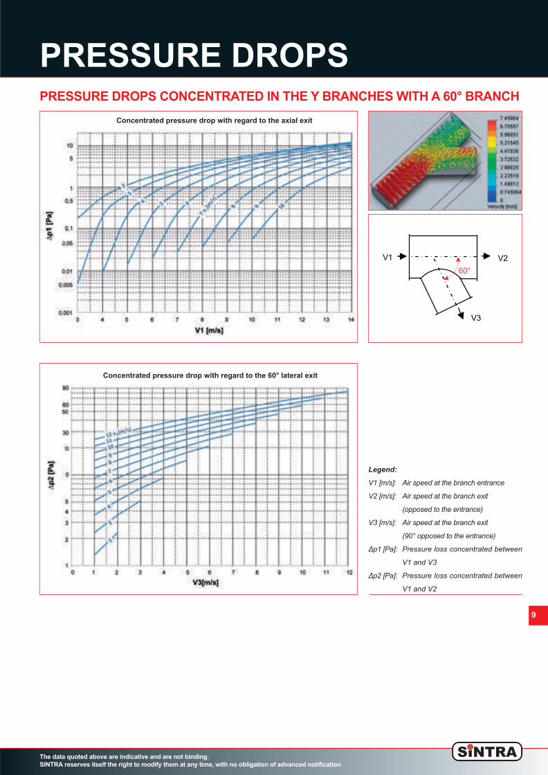
Legend:
V1 [m/s]: Air speed at the branch entrance
V2 [m/s]: Air speed at the branch exit
(opposed to the entrance)
V3 [m/s]: Air speed at the branch exit
(90° opposed to the entrance)
Δp1 [Pa]: Pressure loss concentrated between
V1 and V3
Δp2 [Pa]: Pressure loss concentrated between
V1 and V2
PRESSURE DROPS CONCENTRATED IN THE Y BRANCHES WITH A 60° BRANCH
Concentrated pressure drop with regard to the axial exit
Concentrated pressure drop with regard to the 60° lateral exit
02_Spiropack_ing_v8 ok_Layout 1 24/10/12 17.51 Pagina 9

10
The data quoted above are indicative and are not binding.
SINTRA reserves itself the right to modify them at any time, with no obligation of advanced notification
ny use or reproduction af any part of this docum
ent in any w
ay, all the filling or databases or other system
s are not allow
ed w
othout previous w
ritten confirm
ation by S
IN
TR
A.
PRESSURE DROPS CONCENTRATED IN THE Y BRANCHES WITH A 45° BRANCH
Legend:
V1 [m/s]: Air speed at the branch entrance
V2 [m/s]: Air speed at the branch exit
(opposed to the entrance)
V3 [m/s]: Air speed at the branch exit
(90° opposed to the entrance)
Δp1 [Pa]: Pressure loss concentrated between
V1 and V3
Δp2 [Pa]: Pressure loss concentrated between
V1 and V2
V2V1
V3
45°
PRESSURE DROPS
Concentrated pressure drop with regard to the axial exit
Concentrated pressure drop with regard to the 45° lateral exit
02_Spiropack_ing_v8 ok_Layout 1 24/10/12 17.51 Pagina 10
11
PRESSURE DROPS
The data quoted above are indicative and are not binding.
SINTRA reserves itself the right to modify them at any time, with no obligation of advanced notification
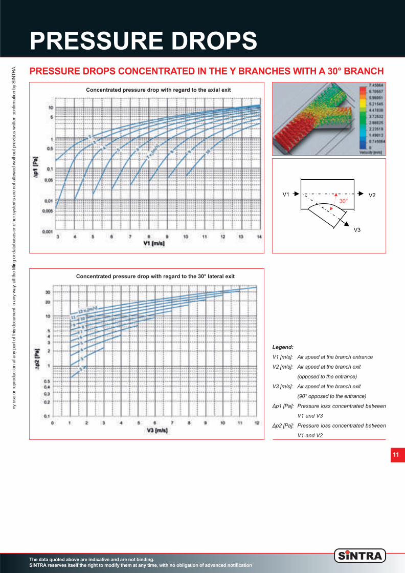
PRESSURE DROPS CONCENTRATED IN THE Y BRANCHES WITH A 30° BRANCH
V2V1
V3
30°
Legend:
V1 [m/s]: Air speed at the branch entrance
V2 [m/s]: Air speed at the branch exit
(opposed to the entrance)
V3 [m/s]: Air speed at the branch exit
(90° opposed to the entrance)
Δp1 [Pa]: Pressure loss concentrated between
V1 and V3
Δp2 [Pa]: Pressure loss concentrated between
V1 and V2
ny use or reproduction af any part of this docum
ent in any w
ay, all the filling or databases or other system
s are not allow
ed w
othout previous w
ritten confirm
ation by S
IN
TR
A.
Concentrated pressure drop with regard to the axial exit
Concentrated pressure drop with regard to the 30° lateral exit
02_Spiropack_ing_v8 ok_Layout 1 24/10/12 17.51 Pagina 11

PRESSURE LOSSES
The data quoted above are indicative and are not binding.
SINTRA reserves itself the right to modify them at any time, with no obligation of advanced notification
ny use or reproduction af any part of this docum
ent in any w
ay, all the filling or databases or other system
s are not allow
ed w
othout previous w
ritten confirm
ation by S
IN
TR
A.
CONCENTRATED PRESSURE LOSSES
VOLUMETRIC MASS CHART FOR THE HUMID AIR AT 1013 mbar - SI UNIT (Kg/m
3
)
Localized pressure losses are determined by the following formula:Pc = ξ * ρ * v2/2 where:Pc = localized pressure loss (Pa)ξ = localized pressure loss coefficient, dimensionlessρ = air’s volumetric mass (Kg/m3)V = air’s medium speed (m/s) 12
TEMPERATURE RELATIVE HUMIDITY
°C °F SECCA 10 20 30 40 50 60 70 80 90 100
-15 5 1.368 1.366 1.366 1.366 1.366 1.366 1.366 1.365 1.365 1.365 1.365
-10 14 1.342 1.40 1.340 1.340 1.340 1.339 1.339 1.339 1.339 1.339 1.339
-5 23 1.317 1.315 1.315 1.314 1.314 1.314 1.314 1.314 1.314 1.313 1.313
0 32 1.293 1.291 1.290 1.290 1.290 1.289 1.289 1.289 1.289 1.288 1.288
5 41 1.270 1.267 1.267 1.267 1.266 1.266 1.265 1.265 1.265 1.264 1.264
10 50 1.247 1.245 1.244 1.244 1.243 1.243 1.242 1.241 1.241 1.240 1.240
15 59 1.226 1.223 1.222 1.221 1.221 1.220 1.219 1.218 1.218 1.217 1.216
20 68 1.205 1.202 1.201 1.200 1.199 1.199 1.197 1.196 1.195 1.194 1.192
25 77 1.185 1.181 1.180 1.179 1.177 1.176 1.174 1.173 14.172 1.170 1.169
30 86 1.165 1.161 1.160 1.158 1.156 1.154 1.152 1.150 1.149 1.147 1.145
35 95 1.146 1.142 1.140 1.137 1.135 1.1133 1.130 1.128 1.129 1.123 1.121
40 104 1.128 1.123 1.120 1.119 1.117 1.111 1.108 1.104 1.101 1.098 1.1095
45 113 1.110 1.104 1.101 1.097 1.093 1.089 1.085 1.081 1.077 1.073 1.069
50 122 1.093 1.086 1.081 1.076 1.071 1.066 1.061 1.056 1.051 1.046 1.041
55 131 1.076 1.068 1.062 1.056 1.049 1.043 1.037 1.031 1.021 1.018 1.012
60 140 1.060 1.0151 1.043 1.035 1.027 1.019 1.011 1.004 1.996 0.988 0.950
65 149 1.044 1.033 1.023 1.014 1.004 0.994 0.985 0.0975 0.965 0.956 0.946
70 158 1.029 1.016 1.004 0.992 0.980 0.938 0.956 0.944 0.932 0.920 0.908
75 167 1.014 0.998 0.984 0.969 0.955 0.940 0.926 0.911 0.897 0.882 0.868
80 176 1.000 0.981 0.963 0.946 0.928 0.911 0.893 0.875 0.858 0.842 0.823
85 185 0.986 0.963 0.942 0.921 0.900 0.879 0.857 0.836 0.815 0.794 0.773
90 194 0.973 0.946 0.920 0.895 0.870 0.744 0.719 0.794 0.768 0.743 0.718
95 203 0.959 0.928 0.898 0.867 0.837 0.807 0.777 0.747 0.717 0.687 0.657
100 212 0.946 0.909 0.874 0.838 0.802 0.767 0.731 0.696 0.660 0.624 0.589
02_Spiropack_ing_v8 ok_Layout 1 24/10/12 17.51 Pagina 12

PRESSURE LOSSES
The data quoted above are indicative and are not binding.
SINTRA reserves itself the right to modify them at any time, with no obligation of advanced notification
ny use or reproduction af any part of this docum
ent in any w
ay, all the filling or databases or other system
s are not allow
ed w
othout previous w
ritten confirm
ation by S
IN
TR
A.
13
PRESSURE LOSSES CONCENTRATED IN THE BENDS
Localized pressure losses are determined by the following formula:Pc = ξ * ρ * v2/2 where:Pc = localized pressure loss (Pa) • ξ = localized pressure loss coefficient, dimensionlessρ = air’s volumetric mass (Kg/m3) • V = air’s medium speed (m/s)
90° bend 30°, 45° and 60° bends
Parted 90° bend Parted 30°, 45° and 60° bends
Rough edge 90° bend Rough edge 30°, 45° and 60° bends
02_Spiropack_ing_v8 ok_Layout 1 24/10/12 17.51 Pagina 13

PRESSURE LOSSES
The data quoted above are indicative and are not binding.
SINTRA reserves itself the right to modify them at any time, with no obligation of advanced notification
14
ny use or reproduction af any part of this docum
ent in any w
ay, all the filling or databases or other system
s are not allow
ed w
othout previous w
ritten confirm
ation by S
IN
TR
A.
CONCENTRATED PRESSURE LOSSES: INLETS AND OUTLETS
Localized pressure losses are determined by the following formula:Pc = ξ * ρ * v2/2 where:Pc = localized pressure loss (Pa) • ξ = localized pressure loss coefficient, dimensionlessρ = air’s volumetric mass (Kg/m3) • V = air’s medium speed (m/s)
Inlet without lead hole Outlet without lead hole
Inlet without lead hole with frontal obstacle Outlet without lead hole with frontal obstacle
Inlet with lead hole with frontal obstacle Outlet with lead hole with frontal obstacle
Inlet with midriff
A: section’s area of the duct
A*: midriff passing area
A: section’s area of the duct
A*: midriff passing area
Outlet with midriff
Inlet with lead hole Outlet with lead hole
02_Spiropack_ing_v8 ok_Layout 1 24/10/12 17.51 Pagina 14

PRESSURE LOSSES
The data quoted above are indicative and are not binding.
SINTRA reserves itself the right to modify them at any time, with no obligation of advanced notification
ny use or reproduction af any part of this docum
ent in any w
ay, all the filling or databases or other system
s are not allow
ed w
othout previous w
ritten confirm
ation by S
IN
TR
A.
15
CONCENTRATED PRESSURE LOSSES
Localized pressure losses are determined by the following formula:Pc = ξ * ρ * v2/2 where:Pc = localized pressure loss (Pa) • ξ = localized pressure loss coefficient, dimensionlessρ = air’s volumetric mass (Kg/m3) • V = air’s medium speed (m/s)
Narrowing without lead hole Narrowing without lead hole
Widening without lead hole Widening without lead hole
Balancing midriff Pipes and rods going through the duct
Butterfly regulator Damper regulator
Protection mesh Perforated metal sheet
A: section’s area of the duct
A*: midriff passing area
A: section’s area of the duct
A*: midriff passing area
02_Spiropack_ing_v8 ok_Layout 1 24/10/12 17.51 Pagina 15

16
PRESSURE LOSSES
The data quoted above are indicative and are not binding.
SINTRA reserves itself the right to modify them at any time, with no obligation of advanced notification
ny use or reproduction af any part of this docum
ent in any w
ay, all the filling or databases or other system
s are not allow
ed w
othout previous w
ritten confirm
ation by S
IN
TR
A.
PRESSURE LOSSES IN THE CONNECTION PIECES
Localized pressure losses are determined by the following formula:Pc = ξ * ρ * v2/2 where:Pc = localized pressure loss (Pa) • ξ = localized pressure loss coefficient, dimensionlessρ = air’s volumetric mass (Kg/m3) • V = air’s medium speed (m/s)
90° T branch 30°, 45° and 60° Y branch
90° T branch with tapering 30°, 45° and 60° Y branch with tapering
Double bend branch Double bend confluence
Double Y branch Double Y confluence
T branch T confluence
02_Spiropack_ing_v8 ok_Layout 1 24/10/12 17.51 Pagina 16

17
CONNECTION PIECES
The data quoted above are indicative and are not binding.
SINTRA reserves itself the right to modify them at any time, with no obligation of advanced notification
ny use or reproduction af any part of this docum
ent in any w
ay, all the filling or databases or other system
s are not allow
ed w
othout previous w
ritten confirm
ation by S
IN
TR
A.
These are examples of standard pieces. Custom pieces can be produced according to the customer’s needs.
T BRANCH
Y BRANCH 30 ° - 45° - 60°
BENDS
02_Spiropack_ing_v8 ok_Layout 1 24/10/12 17.51 Pagina 17

CONNECTION PIECES
The data quoted above are indicative and are not binding.
SINTRA reserves itself the right to modify them at any time, with no obligation of advanced notification
ny use or reproduction af any part of this docum
ent in any w
ay, all the filling or databases or other system
s are not allow
ed w
othout previous w
ritten confirm
ation by S
IN
TR
A.
18
ECCENTRICAL TAPERING
LENGTH L (mm)
Ø A (mm) 200-400 450-600 650-800 850-1000 1050-1200 1250-1400 1450-1600
= øA -50mm 800 800 800 700 700 700 700
Ø B (mm) = øA -100mm 800 800 800 700 700 700 700
= øA -150mm / / / / / / /
CONCENTRICAL TAPERING
LENGTH L (mm)
Ø A (mm) 200-400 450-600 650-800 850-1000 1050-1200 1250-1400 1450-1600
= øA -50mm 800 800 800 800 800 800 800
Ø B (mm) = øA -100mm 800 800 800 800 800 800 800
= øA -150mm 800 800 800 / / / /
These are examples of standard pieces. Custom pieces can be produced according to the customer’s needs.
02_Spiropack_ing_v8 ok_Layout 1 24/10/12 17.51 Pagina 18

ACCESSORIES
The data quoted above are indicative and are not binding.
SINTRA reserves itself the right to modify them at any time, with no obligation of advanced notification
ny use or reproduction af any part of this docum
ent in any w
ay, all the filling or databases or other system
s are not allow
ed w
othout previous w
ritten confirm
ation by S
IN
TR
A.
19
DESCRIPTION MEASURES H THICKNESS HOLE TENSILE LOAD PIECES IN
- NEWTON - BOX
D L mm mm Ø mm CUT RESISTANCE N°
STAINLESS STEEL 32 60 6,5 1.0 - 3.0 3,3 2700 3000 1000
STAINLESS STEEL 32 100 6,5 5.0 - 7.0 3,3 2700 3000 1000
GALVANIZED STEEL 32 60 6,5 2.0 - 3.0 3,3 1300 1650 1000
GALVANIZED STEEL 32 100 6,5 6.0 - 7.0 3,3 1300 3000 1000
ABS GASKET FOR PIECES’ JUNCTION
LIQUID GASKET
The ABS gasket is suggested for plants with installation heights over 4m and available static pressures over 140Pa. Thanks to the particular
shape of the profile, the installation on the duct’s edge folding is simple and quick.
The liquid gasket has to be applied on the closure of each single piece, and it is suggested
for plants with installation heights above 5m and available static pressures above 200Pa.
FIXING RIVETS
The fixing rivets can be in
stainless steel or galvanized
steel.
Stainless steel is suggested
for diameters bigger than
900 mm.
02_Spiropack_ing_v8 ok_Layout 1 24/10/12 17.51 Pagina 19

ACCESSORIES
The data quoted above are indicative and are not binding.
SINTRA reserves itself the right to modify them at any time, with no obligation of advanced notification
ny use or reproduction af any part of this docum
ent in any w
ay, all the filling or databases or other system
s are not allow
ed w
othout previous w
ritten confirm
ation by S
IN
TR
A.
20
COMPRESSOR AND RIVETING GUN
JUNCTION COLLARS
High quality air compressor, complying to the highest international standards. It is extremely manageable, easy to use and with low
noise production. It is used, together with the riveting gun, to close the duct’s modules on site, reducing:
• installation times
• manipulation of the pieces
• damage risks due to manipulation
Compressor’s technical characteristics: 230V/50HZ,2HP,50L
Riveting gun’s technical characteristics:
• Ø rivets: from 2.4mm to 4.8mm
• max length of the head: 14mm
• weight: 1.8kg
• working pressure: 6.3kg/cm2
• max closing effort: 8360Nm
Ø (G) (H) (S) thickness
mm mm mm mm mm
250 8 37 8 0.8
280 8 37 8 0.8
300 8 37 8 0.8
315 8 37 8 0.8
350 8 37 8 0.8
355 8 37 8 0.8
400 10 38 10 0.8
450 10 38 10 0.8
500 10 38 10 1.0
550 10 38 10 1.0
560 10 38 10 1.0
Ø (G) (H) (S) thickness
mm mm mm mm mm
600 10 38 10 1.0
630 10 38 10 1.0
650 10 38 10 1.0
700 10 38 10 1.0
750 10 38 10 1.0
800 14 42 13 1.0
850 14 42 13 1.0
900 14 42 13 1.0
950 14 42 13 1.0
1000 14 42 13 1.0
1050 14 42 13 1.0
Ø (G) (H) (S) thickness
mm mm mm mm mm
1100 14 42 13 1.0
1150 14 42 13 1.0
1200 14 42 13 1.0
1250 14 42 13 1.0
1300 14 42 13 1.0
1350 14 42 13 1.0
1400 14 42 13 1.0
1450 14 42 13 1.0
1500 14 42 13 1.0
1550 14 42 13 1.0
1600 14 42 13 1.0
KINDS OF MATERIALS
DUCT’S MATERIAL JUNCTION COLLAR’S MATERIAL
GALVANIZED STEEL GALVANIZED STEEL
AISI 430 STAINLESS STEEL AISI 304 STAINLESS STEEL
AISI 304 STAINLESS STEEI IAISI 304 STAINLESS STEEL
AISI 316 STAINLESS STEEL IAISI 316 STAINLESS STEEL
COPPER COPPER
ALUMINUM AISI 304 STAINLESS STEEL
PAINTED PAINTED
Omega section collar built in one piece for the junction of the duct’s modules.
02_Spiropack_ing_v8 ok_Layout 1 24/10/12 17.51 Pagina 20

DIFFERENT MATERIALS
The data quoted above are indicative and are not binding.
SINTRA reserves itself the right to modify them at any time, with no obligation of advanced notification
ny use or reproduction af any part of this docum
ent in any w
ay, all the filling or databases or other system
s are not allow
ed w
othout previous w
ritten confirm
ation by S
IN
TR
A.
21
GALVANIZED STEEL CZn PAINTED STEEL CEp
SATINIZED INOX Cinox/s POLISHED INOX Cinox/L
ALUMINIUM CAI COPPER CCu
02_Spiropack_ing_v8 ok_Layout 1 24/10/12 17.51 Pagina 21

BRAND CORRESPONDENCE
Structural steels
GALVANIZED STEEL TECHNICAL FILE
S 250 GD + Z EN 10346
The data quoted above are indicative and are not binding.
SINTRA reserves itself the right to modify them at any time, with no obligation of advanced notification
ny use or reproduction af any part of this docum
ent in any w
ay, all the filling or databases or other system
s are not allow
ed w
othout previous w
ritten confirm
ation by S
IN
TR
A.
DIRECTION
THICKNESS
R
e
(MPa) R
m
(MPa) A80(%)
MP GUARANTEES
R90 N90
(MM) (MONTHS)
0.2 - 0.5 ≥ 15
L 0.5 - 0.7 ≥ 250 ≥ 330 ≥ 17 < 1 — —
0.7 - 6 ≥ 19
MECHANICAL
PROPERTIES
Structural steels
DIMENSION
Structural steels
10142:1991
DIN 17162/1
NF A36-321
BS 2989 Z25G
ASTM A653 SS GRADE 230
EN 10142:2000
PN-89/H-92125:1989
EN 10292:2007
EN 10147:2000 S250GD+Z
EN 10326:2004 S250GD+Z
EN 10327:2004
EN 10346:2009 S250GD+Z
EN 10147:1991 FEE250G
DIN 17162/2 STE 250-2Z
NF A36-322 C.250
OLD BRAND NAMES S250GD+Z
THICKNESS (MM) S250GD+Z EN 10346
MAX WIDTH
0.25 ≤ TH ≤ 0.30 1250
0.30 ≤ TH ≤ 0.35 1290
0.35 ≤ TH ≤ 0.40 1350
0.40 ≤ TH ≤ 0.45 1450
0.45 ≤ TH ≤ 0.50 1560
0.50 ≤ TH ≤ 0.55 1640
0.55 ≤ TH ≤ 0.60 1730
0.60 ≤ TH ≤ 0.65 1840
0.65 ≤ TH ≤ 0.70 1860
0.70 ≤ TH ≤ 0.75 1970
0.75 ≤ TH ≤ 0.80 2060
0.80 ≤ TH ≤ 0.85 2060
0.85 ≤ TH ≤ 1.05 2060
1.05 ≤ TH ≤ 1.50 2060
THICKNESS (MM) S250GD+Z EN 10346
MAX WIDTH
1.50 ≤ TH ≤ 1.75 2060
1.75 ≤ TH ≤ 1.80 2060
1.80 ≤ TH ≤ 1.85 2060
1.85 ≤ TH ≤ 1.90 1970
1.90 ≤ TH ≤ 1.95 1920
1.95 ≤ TH ≤ 2.00 1870
2.00 ≤ TH ≤ 2.05 1830
2.05 ≤ TH ≤ 2.10 1780
2.10 ≤ TH ≤ 2.15 1740
2.15 ≤ TH ≤ 2.20 1700
2.20 ≤ TH ≤ 2.25 1690
2.25 ≤ TH ≤ 2.30 1700
2.30 ≤ TH ≤ 2.35 1750
CHEMICAL COMPOSITION
Structural steels
C (%) MN (%) P (%) S (%) SI (%) AL (%) NB (%) TI (%)
≤ 0.200 ≤ 1.70 ≤ 0.100 ≤ 0.045 ≤ 0.60 — — —
COATING PROPERTIES
DESIGNATION EN 10346
COATING WEIGHT COATING THICKNESS
DOUBLE SIDED (G/M
2
) (μM PER SIDE)
Z 140 140 10.0
Sintra, for the construction of the metallic ducts with SPIROPACK™ technology, does notuse classic DX51 galvanized steel, but only selected galvanized steel with qualities abovestandard. This choice, which is necessary to allow the construction of the ducts following high qualitystandards, always allows a detailed control on the material’s characteristics and as a conse-quence, a structural uniformity which is constant in time.
Legenda
Re = yield limit in N/mm²
Rm = mechanical resi stance to breaking in N/mm²
A 80 % = stretching percentage samples 80m mm
22
BLACK BAND
GALVANIZED STEEL
02_Spiropack_ing_v8 ok_Layout 1 24/10/12 17.51 Pagina 22

STAINLESS STEEL TECHNICAL FILE
AISI 430
The data quoted above are indicative and are not binding.
SINTRA reserves itself the right to modify them at any time, with no obligation of advanced notification
ny use or reproduction af any part of this docum
ent in any w
ay, all the filling or databases or other system
s are not allow
ed w
othout previous w
ritten confirm
ation by S
IN
TR
A.
COLD FORMED METAL
SHEET – STRENGTHENED
Our 430 stainless steel can be readily coldformed by all standard processes (bending,contour forming, drawing, deep drawing, flowturning and stretching). The drawing operations which imply a con-siderable “stretching”, can be eased by theinitial forming, by producing modules with awide bending radius.
This grade complies with:
• Stainless Europe material safety data
sheet n° 1: stainless steel (European
directive 2001/58/EC)
• European directive 2000/53/EC on end-
of-life vehicles, and on the annex II
dated 27 june 2002.
• NFA 36 711 standard “stainless steel in-
tended for use in contact with food-
stuffs, products and beverages for
human and animal consumption (non
packaging steel)
• Requirements of NSF/ANSI 51 – 2007
international standard edition for “Food
Equipment Materials” and of the FDA
(United States Food and Drug Admini-
stration) regarding materials used for
food contact
• French decree Nr. 92-631 dated 8 July
1992 and Regulation No.1935-2004 of
the European parliament and of the
council of 27 October 2004 on materials
and articles intended to come into con-
tact with food (and repealing directives
80/590/EEC and 89/109/EEC)
• French regulatory paper dated 13 Ja-
nuary 1976 relating to materials and ar-
ticles made of stainless steel in contact
with foodstuffs
CHEMICAL COMPOSITION
PHYSICAL PROPERTIES
Cold rolled sheet - annealed
INOX430 INOX430D
STANDARD ENHANCED FORMING
LEVEL GRADE PERFORMANCE GRADE
Typical values
GRADE EUROPEAN ASTM ERICHSEN
DESIGNATION DESIGNATION A 240 DEFLECTION*
K30 1.4016 TYPE 430 MM 8.7
GRADE EUROPEAN ASTM LDR*
DESIGNATION DESIGNATION A 240 (MM)
K30 1.4016 TYPE 430 2.05-2.10
23
General characteristics
The main characteristics of the AISI 430 stainless steel for applications close to room
temperature are:
• Resistance to corrosion with moderately aggressive media
• It can be readily cold formed by all standard processes (enhanced performance for K30D)
• Excellent aesthetical appearance
AISI 430 stainless steel also have a good resistance to oxidation due to high temperatures.
Sintra, in order to give the ducts a more pleasant appearance without having to bear heavily on the costs, introduced the use of theAISI 430 stainless steel instead of the AISI 304 stainless steel, which can be used in all plants as a substitute for galvanized steel.
GRADE DESIGNATION EUROPEAN DESIGNATION
X6CR17 1.4016
(1)
TYPE 430
(2)
(1)
According to EN 10088-2
(2)
According to ASTM A 240
GRADE
INOX430D INOX430D
DESIGNATION
ELEMENTS % %
C 0.05 0.035
SI 0.35 0.35
MN 0.40 0.40
CR 16.5 16.5
Stretching (Erichsen test)
Deep drawing (Swift test)
DENSITY D KG/DM
3
20°C 7.7
FUSION
°C 1500
TEMPERATURE
SPECIFIC
C J/KG.K 20°C 460
400°C 600
HEAT
800°C 800
THERMAL
K W/M.K 20°C 25
CONDUCTIVITY
MEAN
20-200°C 10.5
COEFFICIENT
A 10
-6
/K 20-400°C 11.5
OF THERMAL
20-600°C 11.7
EXPANSION
20-600°C 12.5
ELECTRICAL
P Ω MM
2
/M 20°C 0.60
RESISTIVITY
MAGNETIC
μ
AT 0.8 KA/M
20°C 1000
PERMEABILITY DC OR AC
YOUNG
E MPA.10
3
20°C 220
MODULUS
Temperature (°C)
E (103 MPa)ρ (Ω.mm2/m) k (W/m.K)
15
20
25
100
200
20 200 400 600 800
E
ρ
k
02_Spiropack_ing_v8 ok_Layout 1 24/10/12 17.51 Pagina 23
STAINLESS STEEL TECHNICAL FILE
AISI 430
Mean stresses (Mpa) for different rupture levels according to
temperature
Mean stresses (Mpa) for 1% elongation at different times accor-
ding to temperature
The data quoted above are indicative and are not binding.
SINTRA reserves itself the right to modify them at any time, with no obligation of advanced notification
ny use or reproduction af any part of this docum
ent in any w
ay, all the filling or databases or other system
s are not allow
ed w
othout previous w
ritten confirm
ation by S
IN
TR
A.
Typical values.* based from specimen 20x50 mm
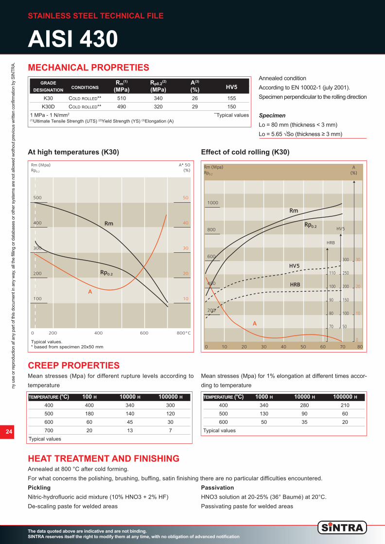
MECHANICAL PROPRETIES
CREEP PROPERTIES
Annealed at 800 °C after cold forming.
For what concerns the polishing, brushing, buffing, satin finishing there are no particular difficulties encountered.
Pickling
Nitric-hydrofluoric acid mixture (10% HNO3 + 2% HF)
De-scaling paste for welded areas
Passivation
HNO3 solution at 20-25% (36° Baumé) at 20°C.
Passivating paste for welded areas
HEAT TREATMENT AND FINISHING
At high temperatures (K30) Effect of cold rolling (K30)
Annealed condition
According to EN 10002-1 (july 2001).
Specimen perpendicular to the rolling direction
SpecimenLo = 80 mm (thickness < 3 mm)
Lo = 5.65 √So (thickness ≥ 3 mm)
GRADE Rm
(1)
Rp0.2
(2)
A
(3)
DESIGNATION
CONDITIONS
(MPa) (MPa) (%)
HV5
K30 COLD ROLLED** 510 340 26 155
K30D COLD ROLLED** 490 320 29 150
1 MPa - 1 N/mm
2 **
Typical values
(1)
Ultimate Tensile Strength (UTS)
(2)
Yield Strength (YS)
(3)
Elongation (A)
TEMPERATURE (°C) 100 H 10000 H 100000 H
400 400 340 300
500 180 140 120
600 60 45 30
700 20 13 7
Typical values
TEMPERATURE (°C) 1000 H 10000 H 100000 H
400 340 280 210
500 130 90 60
600 50 35 20
Typical values
24
02_Spiropack_ing_v8 ok_Layout 1 24/10/12 17.51 Pagina 24

STAINLESS STEEL TECHNICAL FILE
AISI 430
The data quoted above are indicative and are not binding.
SINTRA reserves itself the right to modify them at any time, with no obligation of advanced notification
ny use or reproduction af any part of this docum
ent in any w
ay, all the filling or databases or other system
s are not allow
ed w
othout previous w
ritten confirm
ation by S
IN
TR
A.
Grade designations
Standards
DesignationsType UNS
3004.130014S30K
K30/K30D 430 S43000 1.4016
K41 441 (1) S43932 1.4509
K45 445 (1) S44500 1.4621 (2)
K36 436 S43600 1.4526
K44 444 S44400 1.4521
17-4Mn 201.1 S20100 (3) 1.4618 (2)
18-9 E 304 S30400 1.4301
17-11 MT 316Ti S31635 1.4571
(1) Common designation.(2) Pending update of the standard.(3) With copper addition and 201.1 «rich side» properties per ASTM A240
ASTMEN
K30/K30D17-4Mn
K03
K4118-9EK45
K44
K3617-11MT
-
+
+10 15 20 25 30
Cor
rosi
on r
esis
tanc
e
PREN
CORROSION RESISTANCE
WELDING
430 stainless steel has a good corrosion resistance in a large number
of applications:
• domestic environments;
• domestic handling of foodstuffs
• soaps and detergents
• alkaline solutions at room temperature
• certain diluted organic acids at room temperature
• neutral and alkaline salt solutions other than those containing hali-
des (chlorides, fluorides, bromides, iodides)
• numerous organic substances
• Oxidation limits the continuous service temperature of 430 stainless
steel to 800°C
NO FILLER METAL WITH FILLER METAL
WELDING
TYPICAL THICKNESSES FILLER METAL SHIELDING GAS*
PROCESS
THICKNESSES
ROD WIRE
RESISTANCE:
≤ 2 MM
SPOT, SEAM
W.N° 1.4370 W.N° 1.4370
TIG < 1.5 MM > 0.5 MM ER 309 L (SI) ER 309 L (SI) ARGON
ER 316 L (SI) ER 316 L (SI)
W.N° 1.4370
PLASMA < 1.5 MM > 0.5 MM ER 309 L (SI) ARGON
ER 316 L (SI)
W.N° 1.4370
ARGON + 2% CO
MIG
(2)
> 0.8 MM ER 309 L (SI)
ER 316 L (SI)
ARGON + 2% O
S.A.W
(2)
> 2 MM
ER 309 L
ER 316 L
ELECTRODE REPAIRS
ER 309 L
ER 316 L
LASER < 5 MM HELIUM
(1)
The S.A.W. process is not recommended, due to the high power input.
(2)
Pulsed MIG welding preferred, due to the lower power input.
In general 430 stainless steel is poorly sui-
ted to welding operations, since it readily
forms martensite in the weld, leading to
brittle and relatively undeformable joints.
However, satisfactory results can be obtai-
ned without having to resort to post-weld
treatments, providing that the welding pro-
cess employed forges the weld sufficiently
and that the welding power is not too high.
430 stainless steel is not recommended for
heavy gage welded structures, due to the
brittleness of the non-forged weld joints.
There is no thermal treatment required
after the welding.
Welding points must be mechanically or
chemically descaled, then passivated.
Localised corrosion resistance
Typical values of pitting corrosion potential in NaCl 0.02M,
23°C, pH6.6 as a function of PREN (%Cr+3.3%Mo+16%N).
25
The data quoted above are indicative and are not binding.
SINTRA reserves itself the right to modify them at any time, with no obligation of advanced notification
02_Spiropack_ing_v8 ok_Layout 1 24/10/12 17.51 Pagina 25

STAINLESS STEEL TECHNICAL FILE
AISI 304
The data quoted above are indicative and are not binding.
SINTRA reserves itself the right to modify them at any time, with no obligation of advanced notification
COLD FORMING
In the strengthened condition, 304 stainless
steel can be readily cold formed by all stan-
dard processes (bending, contour forming,
drawing, deep drawing, flow turning and
stretching). Some forming operations are
easier when performed hot. Subsequent pic-
kling is necessary.
Deep drawing (Swift test)
The Swift test is a method used to determinate
the Limiting Drawing Ratio (LDR). This LDR is
defined by the maximum ratio between the
blank diameter (variable) and the punch diame-
ter (fixed) for which the drawing can be perfor-
med successfully in one step.
This 304 stainless steel complies with:
• Stainless Europe material safety data sheet n° 1: stainless steel (Eu-
ropean directive 2001/58/EC)
• European directive 2000/53/EC on end-of-life vehicles, and on the
annex II dated 27 June 2002.
• NFA 36 711 standard “stainless steel intended for use in contact with
foodstuffs, products and beverages for human and animal consum-
ption (non packaging steel)
• Requirements of NSF / ANSI 51-2009 International edition for "Col-
lective Restoration Materials" and of FDA (United States Food and
Drug Administration) for what concerns materials used for contact
with foodstuffs
• French decree Nr. 92-631 dated 8 July 1992 and Regulation
No.1935-2004 of the European parliament and of the council of 27
October 2004 on materials and articles intended to come into contact
with food (and repealing directives 80/590/EEC and 89/109/EEC)
• French regulatory paper dated 13 January 1976 relating to materials
and articles made of stainless steel in contact with foodstuffs
• Italian decree dated 21 March1973: a list of steel kinds appro-
priate to the “rules for the hygiene of packaging, and instruments
destined to come in contact with foodstuffs or with substances
for personal use”
• PED (Pressure Equipment Directive) according to EN 10028-7 and
AD2000 Merkblatt and W2 and W10 (TÜV WB494).
CHEMICAL COMPOSITION
General characteristics
The main characteristics of the 304 stainless
steel are:
• Good resistance to corrosion in acids and
chlorides containing media
• Very good resistance to pitting corrosion
and crevice corrosion
• Very good resistance to intergranular
corrosion, even after welding
• Excellent weldability
• High ductility
• Good drawability
• Excellent polishing
TEMPERATURE (°C) 100 H 10000 H 100000 H
400 400 340 300
500 180 140 120
600 60 45 30
700 20 13 7
Typical values
TEMPERATURE (°C) 100 H 10000 H 100000 H
400 400 340 300
500 180 140 120
600 60 45 30
700 20 13 7
Typical values
Gradedesignation
LDR* (mm)
18-9E 1.9618-9ED 1.98
18-9DDQ 2.0217-4Mn 1.92
K41 2.29K45 2.28
D
d
LDR = Dmax
d* Limiting Drawing Ratio - Lubricant = Mobilux EP00Typical values tests done on 0.8mm thick.
Temperature (°C)
E (103 MPa)ρ (Ω.mm2/m) k (W/m.K)
15
20
25
100
200
20 200 400 600 800
E
ρ
k
PHYSICAL PROPERTIES
Cold rolled and annealed sheet
DENSITY D KG/DM³ 20 °C 7.9
MELTING TEMPERATURE °C LIQUIDUS 1450
SPECIFIC HEAT C J/KG.K 20 °C 500
THERMAL CONDUCTIVITY K W/M.K 20 °C 15
20-100 °C 16.0
MEAN COEFFICIENT
20-200 °C 16.5
ά 10
-6
/K 20-400 °C 17.0
OF THERMAL EXPANSION
20-600 °C 17.5
20-800 °C 18.0
ELECTRICAL RESISTIVITY ρ Ω MM
2
/M 20 °C 0.73
MAGNETIC PERMEABILITY μ AT 0.8 KA/M DC OR AC 20 °C 1.02
YOUNG’S MODULUS E MPA.10
3
20 °C 200
Poisson’s coefficient: 0.30
ny use or reproduction af any part of this docum
ent in any w
ay, all the filling or databases or other system
s are not allow
ed w
othout previous w
ritten confirm
ation by S
IN
TR
A.
26
02_Spiropack_ing_v8 ok_Layout 1 24/10/12 17.51 Pagina 26

STAINLESS STEEL TECHNICAL FILE
AISI 304
Heat treatment and finishing
Temperature
After cold forming (work hardening) and after
welding (risk of intergranular corrosion in the
weld joint) an annealing treatment for a cou-
ple of minutes at 1075 ± 25°C followed by air
cooling, restores the microstructure (recry-
stallization and dissolution of carbides) and
eliminates internal stresses. After annealing,
pickling followed by passivation is necessary.
Pickling
Nitric-hydrofluoric acid mixture (10% HNO3
+ 2% HF) at room temperature or up to 60°C
Sulfuric-nitric acid mixture (10% H2So4 +
0,5% HNO3) at 60°C
Descaling paste for welded areas
Passivation
20-25% HNO3 solution(36° Baumé) at 20°C
- passivating paste for the welded areas
Polishing
The surface of the 304 stainless steel is in-
dicated for all kinds of polishing (grit, scotch-
brite, electropolishing)
The data quoted above are indicative and are not binding.
SINTRA reserves itself the right to modify them at any time, with no obligation of advanced notification
ny use or reproduction af any part of this docum
ent in any w
ay, all the filling or databases or other system
s are not allow
ed w
othout previous w
ritten confirm
ation by S
IN
TR
A.
20 150
Rm
A
950550 650 750 850300
500
900
60
40
80
100
120
160
140
180
300
100
200
400
600
800
R m (MPa)R p 0.2
A(%)
Rp 0.2
700
Typical values Temperature (°C)0%
R m (MPa)R p
A(%)
Rm
A
Rp
%06%02 40%
200
800
1200
1400
10
20
30
40
50
60
70
1000
600
400
0.2
0.2
Degree of cold work
MECHANICAL PROPRETIES
Size Range
At high temperatures (18-9DDQ) Work hardened condition (18-9E)
According to EN 10002-1 (July 2001), test
piece perpendicular to rolling direction.
Test piece
Length = 80 mm (thickness < 3 mm)
Length = 5.65 √So (thickness ≥ 3 mm)
Cold rolled
2.0 2.50 3.0 3.5 4.0 4.5 5 6.0 7.0 8.0 9.0 10.0 12.0 13.0
Thickness (mm)Hot rolled HRAP 1D Cold rolled HRC 2E (only 18-9E)
1500
2000
1250
1000
Our size range is based on our production capa-
bilities. For the latest information on our offer,
please consult us.
Cold Rolled (width (mm)) Hot Rolled and HRC
GRADE EUROPEAN ASTM Rm
(1)
Rp0.2
(2)
A
(3)
DESIGNATION DESIGNATION A240 (MPa) (MPa) (%)
1B-9E 1.4301 304 670 320 50
18-9ED 1.4301 304 630 300 55
18-9DDQ 1.4301 304 610 270 57
17-4Mn 1.4618 201.1 650 330 50
K41 1.4509 441(a) 480 310 30
K41 1.4621(b) 445(a) 510 360 29
1 MPa - 1 N/mn
2
Typical values
(1)
Ultimate Tensile Strength (UTS)
(2)
Yield Strength (YS)
(3)
Elongation (A)
(a)
Common designation
(b)
Pending update of the standard
0.3 0.4 0.5 0.6 0.7 0.8 0.9 1.0 1.20 1.50 2.0 2.50 3.0 4.0 5.0 6.0 8.0Thickness (mm)
1500
1000
2000
1250
Cold rolled 2D, 2B Cold rolled BA (2R) and 2D, 2B Cold rolled BA (2R) only for 18-9E & 18-9ED
27
02_Spiropack_ing_v8 ok_Layout 1 24/10/12 17.51 Pagina 27
(1)
ER 308L (AWS A5.9) = G 19 9 L (NF EN ISO 14343)
(2)
ER 347 (AWS A5.9) = G 19 9 Nb (NF EN ISO 14343)
(3)
E308L (AWS A5.4) = E 19 9 L (EN1600)
(4)
E347 (AWS A5.4) = E 19 9 Nb (EN1600)
STAINLESS STEEL TECHNICAL FILE
AISI 304
The data quoted above are indicative and are not binding.
SINTRA reserves itself the right to modify them at any time, with no obligation of advanced notification
ny use or reproduction af any part of this docum
ent in any w
ay, all the filling or databases or other system
s are not allow
ed w
othout previous w
ritten confirm
ation by S
IN
TR
A.
Pitti
ng p
oten
tial i
n a
NaCl
0.0
2M, p
H =
6.6
aera
ted
envir
onm
ent a
t 23°
C / p
ittin
g po
tent
ial (
mV/
ECS)
17-4Mn
18-9E/18-9ED/18-9DDQ
K45
-
+
+10 15 20 25 30
K03
K41
18-11ML
PREN (CR+3.3Mo+16N)
pH K45
18-11ML18-11ML18-11ML18-11ML
17-4 Mn
18-9E/18-9L18-9E/18-9L18-9E/18-9L18-9E/18-9L
1,5
2,5
2
-
+
Cre
vice
cor
rosi
on re
sist
ance
K41
Depassivation pH in a deaerated NaCl 2M environment at 23°C
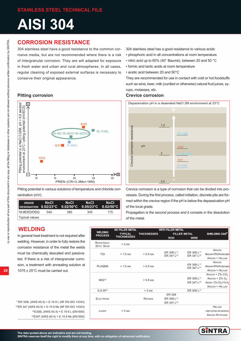
CORROSION RESISTANCE
Pitting corrosion Crevice corrosion
304 stainless steel have a good resistance to the common cor-
rosive media, but are not recommended where there is a risk
of intergranular corrosion. They are will adapted for exposure
in fresh water and urban and rural atmospheres. In all cases,
regular cleaning of exposed external surfaces is necessary to
conserve their original appearance.
304 stainless steel has a good resistance to various acids:
• phosphoric acid in all concentrations at room temperature
• nitric acid up to 65% (40° Baumé), between 20 and 50 °C
• formic and lactic acids at room temperature
• acetic acid between 20 and 50°C
They are recommended for use in contact with cold or hot foodstuffs
such as wine, beer, milk (curdled or otherwise) natural fruit juices, sy-
rups, molasses, etc.
Pitting potential in various solutions of temperature and chloride con-
centration (mV).
Crevice corrosion is a type of corrosion that can be divided into pro-
cesses. During the first process, called initiation, discrete pits are for-
med within the crevice region if the pH is below the depassivation pH
of the local grade.
Propagation is the second process and it consists in the dissolution
of the metal.
28
GRADE NACI NACI NACI NACI
DESIGNATION 0.02/23°C 0.02/50°C 0.05/23°C 0.02/50°C
18-9E/ED/DDQ 540 385 305 175
Typical values
WELDING NO FILLER METAL WITH FILLER METAL
WELDING
TYPICAL THICKNESSES FILLER METAL SHIELDING GAS*
PROCESS
THICKNESSES
ROD WIRE
RESISTANCE:
< 2 MM
SPOT, SEAM
ER 308 L
(1)
ER 308 L
(1)
ARGON
TIG < 1.5 MM > 0.5 MM ARGON+5%HYDROGEN
ER 347 L
(2)
ER 347 L
(2)
ARGON + HELIUM
ER 308 L
(1)
ARGON
PLASMA < 1.5 MM > 0.5 MM ARGON+5%HYDROGEN
ER 347 L
(2)
ARGON + HELIUM
ARGON + 2% CO
2
MIG
(2)
> 0.8 MM
ER 308 L
(1)
ARGON + 2% O
2
ER 347 L
(2)
ARGON + 2% CO
2
+1% H
2
ARGON + HELIUM
S.A.W
(2)
> 2 MM ER 308 L
(1)
ER 308
ELECTRODE REPAIRS ER 308 L
(1)
ER 347 L
(2)
HELIUM
LASER < 5 MM UNDER CERTAIN CIRCUMSTANCES
ARGON NITROGEN
In general heat treatment is not required after
welding. However, in order to fully restore the
corrosion resistance of the metal the welds
must be chemically descaled and passiva-
ted. If there is a risk of intergranular corro-
sion, a treatment with annealing solution at
1075 ± 25°C must be carried out.
02_Spiropack_ing_v8 ok_Layout 1 24/10/12 17.51 Pagina 28

STAINLESS STEEL TECHNICAL FILE
AISI 316/316L
The data quoted above are indicative and are not binding.
SINTRA reserves itself the right to modify them at any time, with no obligation of advanced notification
29
COLD FORMING
In the strengthened condition, 316/316L
stainless steel can be readily cold formed by
all standard processes (bending, contour for-
ming, drawing, deep drawing, flow turning
and stretching).
Deep drawing (Swift test)
The Swift test is a method used to determinate
the Limiting Drawing Ratio (LDR). This LDR is
defined by the maximum ratio between the
blank diameter (variable) and the punch diame-
ter (fixed) for which the drawing can be perfor-
med successfully in one step.
This 316/316L stainless steel complies with:
• Stainless Europe material safety data sheet n° 1: stainless steel
(European directive 2001/58/EC)
• European directive 2000/53/EC on end-of-life vehicles, and on the
annex II dated 27 June 2002.
• PED (pressure equipment directive) according to EN 10028-7
andAD2000 Merkblatt W2 e W10 (TUV WB494)
• NFA 36 711 standard “stainless steel intended for use in contact
with foodstuffs, products and beverages for human and animal con-
sumption (non packaging steel)
• Requirements of NSF / ANSI 51-2009 International edition for "Col-
lective Restoration Materials" and of FDA (United States Food and
Drug Administration) for what concerns materials used for contact
with foodstuffs
• French decree Nr. 92-631 dated 8 July 1992 and Regulation
No.1935-2004 of the European parliament and of the council of 27
October 2004 on materials and articles intended to come into con-
tact with food (and repealing directives 80/590/EEC and
89/109/EEC)
• French regulatory paper dated 13 January 1976 relating to mate-
rials and articles made of stainless steel in contact with foodstuffs
• Italian decree dated 21 March1973: a list of steel kinds appropriate to
the “rules for the hygiene of packaging, and instruments destined to
come in contact with foodstuffs or with substances for personal use”
CHEMICAL COMPOSITION
The main characteristics of the 304 stainless
steel are:
• Good resistance to corrosion in acids and
chlorides containing media
• Very good resistance to pitting corrosion
and crevice corrosion
• Very good resistance to intergranular cor-
rosion, even after welding
• Excellent weldability
• High ductility
• Good drawability
• Excellent polishing
ELEMENTS% C SI MN CR NI MO
18-11ML ≤ 0.02 0.40 1.20 16.70 10.05 2.05
Typical values
GRADE EUROPEAN AMERICAN
DESIGNATION DESIGNATION DESIGNATION
IMDS NR
18-11ML
X5CRNIMO 17- UNS 31600/
2934460
12-2/1.4401
(1)
TYPE 316
(2)
18-11ML
X5CRNIMO 17- UNS 31603/
2934460
12-2/1.4404
(1)
TYPE 316L
(2)
(1)
According to EN 10088-2
(2)
According to ASTM A240
Gradedesignation LDR*
18-11ML 2.01DX22-05 1.9 – 1.95
K44 2.10 - 2.15* Limiting Drawing Ratio – Lubricant = Mobilux EP00 0.8 mm thick sheet
D
d
LDR = Dmax
d
Temperature (°C)
E (103 MPa)ρ (Ω.mm2/m) k (W/m.K)
15
20
25
100
200
20 200 400 600 800
E
ρ
k
PHYSICAL PROPERTIES
Cold rolled sheet - annealed
DENSITY D KG/DM³ 20 °C 7.9
MELTING TEMPERATURE °C LIQUIDUS 1440
SPECIFIC HEAT C J/KG.K 20 °C 500
THERMAL CONDUCTIVITY K W/M.K 20 °C 15
MEAN COEFFICIENT OF THERMAL
20-100 °C 16.0
ά 10
-6
/K 20-300 °C 17.0
THERMAL EXPANSION
20-500 °C 18.0
ELECTRICAL RESISTIVITY ρ Ω MM
2
/M 20 °C 0.75
MAGNETIC PERMEABILITY μ AT 0.8 KA/M DC OR AC 20 °C 1005
YOUNG’S MODULUS E MPA.10
3
20 °C 200
ny use or reproduction af any part of this docum
ent in any w
ay, all the filling or databases or other system
s are not allow
ed w
othout previous w
ritten confirm
ation by S
IN
TR
A.
02_Spiropack_ing_v8 ok_Layout 1 24/10/12 17.51 Pagina 29

STAINLESS STEEL TECHNICAL FILE
AISI 316/316L
Heat treatment and finishing
Temperature
After cold forming (work hardening) and after welding (risk of in-
tergranular corrosion in the weld joint) an annealing treatment for
a couple of minutes at 1075 ± 25°C followed by air cooling, resto-
res the microstructure (recrystallization and dissolution of carbi-
des) and eliminates internal stresses. After annealing, pickling
followed by passivation is necessary.
Pickling
Nitric-hydrofluoric acid mixture (10% HNO3 + 2% HF) st room
temperature or up to 60°C
Sulfuric-nitric acid mixture (10% H2So4 + 0,5% HNO3) at 60°C
Descaling paste for welded areas
Passivation
20-25% HNO3 solution (36° Baumé) at 20°C - passivating paste
for the welded areas
Polishing
The surface of the 316/316L stainless steel is indicated for all
kinds of polishing (grit, scotch-brite, electropolishing)
The data quoted above are indicative and are not binding.
SINTRA reserves itself the right to modify them at any time, with no obligation of advanced notification
0
Rm
A
800 600200 400
300
500
600
700
20
10
70
30
50
60
400
200
100
40
Rm (MPa)Rp0.2
A(%)
Rp0.2
Typical values Temperature (°C)
1400
1800
806040200
10
20
30
200
Rm
Rm (MPa)
Rp0.2
A(%)
1000
2000
40
600
Rp0.2
A
800
400
1200
1600
Degree of cold work
MECHANICAL PROPRETIES
At elevated temperatures Work hardened condition
In the annealed condition. In accordance EN10002-1 (July 2001), test piece perpendicu-lar to rolling direction.Test pieceLength = 80 mm (thickness < 3 mm)Length = 5.65 √So (thickness ≥ 3 mm)Cold rolled
Our size range is based on our productioncapabilities. For the latest information onour offer, please consult us.
GRADE EUROPEAN ASTM Rm
(1)
Rp0.2
(2)
A
(3)
DESIGNATION DESIGNATION A240 (MPa) (MPa) (%)
18-11ML 1.4001/4404 316/316L 620 310 48
22-05 1.4462 2205 840 620 29
K44 1.4521 444 520 380 28
1 MPa - 1 N/mn
2
Typical values
(1)
Ultimate Tensile Strength (UTS)
(2)
Yield Strength (YS)
(3)
Elongation (A)
2.0 2.50 3.0 3.5 4.0 4.5 5 6.0 7.0 8.0 9.0 10.0 12.0 13.0
Thickness (mm)
Width (mm)
Hot rolled HRAP 1D Cold rolled HRC 2E
1500
2000
1250
1000
0.3 0.4 0.5 0.6 0.7 0.8 0.9 1.0 1.20 1.50 2.0 2.50 3.0 4.0 5.0 6.0 8.0
Thickness (mm)
Width (mm)
Cold rolled 2D, 2B
1500
1000
2000
1250
Cold rolled BA (2R) and 2D, 2B
Size Range Cold Rolled Hot Rolled and HRC
ny use or reproduction af any part of this docum
ent in any w
ay, all the filling or databases or other system
s are not allow
ed w
othout previous w
ritten confirm
ation by S
IN
TR
A.
30
02_Spiropack_ing_v8 ok_Layout 1 24/10/12 17.51 Pagina 30

STAINLESS STEEL TECHNICAL FILE
AISI 316/316L
The data quoted above are indicative and are not binding.
SINTRA reserves itself the right to modify them at any time, with no obligation of advanced notification
31
(1)
ER 316L (AWS A5.9) = G 19 12 3 L (EN 14343)
(2)
E 316L (AWS A5.4) = E 19 12 3 L (EN 1600)
Qualsiasi utilizzazione o riproduzione di qualunque parte di questo docum
ento, in qualsiasi form
a o m
odo, tutte le archivazioni su database o altro sistem
a di archiviazione non sono consentiti senza l’accordo preventivo e scritto di S
intra.
8070503010 90 100 %604020
18-9L18-9L18-9L18-9L
80
1ML1ML18 -
30
40
20
70
50
60
°C
10
Sulfuric acid
18 1
CORROSION RESISTANCE
Pitting corrosion Crevice corrosion
Depassivation pH in a deaerated NaCl 2Menvironment at 23°C
Intergranular corrosion
AISI 316/316L stainless steel has an excellent resistance in acid solutions and shows a good resistance in chloride-containing media.
This steel is then used for the production of parts which come into contact with low temperature salt water.
This steel is also recommended where
there is a risk of intergranular corrosion
by meeting the following requirements of
the standard intergranular corrosion
tests: EN ISO 3651-2 (sensitizing treat-
ments T1and T2), ASTM A 262, ex DIN
50914.
Pitting potential in various solu-
tions of temperature and chloride
concentration (mV).
K44 and double DX2205 (1.4462) and
DX2304 (1.4362) are alternatives for 8-
11ML. Thanks to their higher resistance to
corrosion, duplex pitting potentials cannot
be determined in such conditions of tempe-
rature (23°C) and chloride concentration
(0.02M). To consider
them, please report
to their specific data
sheets.
Crevice corrosion is a type of corrosion that
can be divided into processes.
During the first process, called initiation, di-
screte pits are formed within the crevice re-
gion if the pH is below the depassivation pH
of the local grade.
Propagation is the second process and it
consists in the dissolution of the metal.
GRADE NACI NACI NACI NACI
DESIGNATION 0.02/23°C 0.02/50°C 0.05/23°C 0.02/50°C
18-11ML 630 500 455 270
Typical values
WELDING
NO FILLER METAL WITH FILLER METAL
WELDING
TYPICAL THICKNESSES FILLER METAL SHIELDING GAS*
PROCESS
THICKNESSES
ROD WIRE
RESISTANCE:
< 2 MM
SPOT, SEAM
ARGON
TIG < 1.5 MM > 0.5 MM ER 316 L
(1)
ER 316 L
(1)
ARGON+5%HYDROGEN
ARGON + HELIUM
ARGON
PLASMA < 1.5 MM > 0.5 MM ER 316 L
(1)
ARGON+5%HYDROGEN
ARGON + HELIUM
ARGON + 2% CO
2
MIG > 0.8 MM ER 316 L SI
(1)
ARGON + 2% O
2
ARGON + 2% CO
2
+1% H
2
ARGON + HELIUM
S.A.W > 2 MM ER 316 L
(1)
ELECTRODE REPAIRS ER 316 L
(1)
HELIUM
LASER < 5 MM UNDER CERTAIN CIRCUMSTANCES
ARGON NITROGEN
In general heat treatment is not required after
welding. However, in order to fully restore the
corrosion resistance of the metal, the welds
must be mechanically or chemically desca-
led and passivated. In case of applications
at temperatures above 500°C, a specific filler
material has to be used to guarantee a ferrite
level below 8% in the weld.
17-4Mn
18-9L/18-10L
K45
-
+
+10 15 20 25 30
K03
K41
18-11ML
17-11MT
K44
PREN (CR+3,3Mo+16N)
Pit
tin
g p
ote
nti
al
in a
Na
CI
0.0
2M
, p
H=
6.6
are
ate
d
en
vir
on
me
nt
at
23
°C (
mV
/SC
E)
pH
18-11ML18-11ML18-11ML18-11ML
17-4 Mn
18-12MS18-12MS18-12MS18-12MS
22-05
304/304L304/304L304/304L304/304L
301LN301LN301LN301LN
1,5
1
2,5
2
3,5
3
+
Cre
vice
cor
rosi
on re
sist
ance
K03
K44K45
02_Spiropack_ing_v8 ok_Layout 1 24/10/12 17.51 Pagina 31

Description
It is the most popular between stainless steels.
Austenitic stainless steel, non-magnetic at the annealed state, slightly magnetic if cold rolled.
Hardenable through cold forming.
Good mechanical characteristics, not too elevated when at room temperature but excellent at very low temperatures, particularly
for what concerns resilience as well as the high resistance to effort with little sensitivity to incisions.
Indicative analisys %
SUMMARY OF THE DIFFERENT TYPES OF
STAINLESS STEEL
The data quoted above are indicative and are not binding.
SINTRA reserves itself the right to modify them at any time, with no obligation of advanced notification
ny use or reproduction af any part of this docum
ent in any w
ay, all the filling or databases or other system
s are not allow
ed w
othout previous w
ritten confirm
ation by S
IN
TR
A.
AISI 304
Indicative correspondance
Physical characteristics
Elasticity module: 200.000 [N/mm2]
Thermal conductivity: 15 [W/mK]
Specific heat: 500 [J/KgK]
Coefficients of (20°-200°C) 16.5 [10
-6
K
-1
]
thermal expansion: (20°- 400°C) 17.5 [10
-6
K
-1
]
(20°- 600°C) 18.5 [10
-6
K
-1
]
Mechanical characteristics at room temperature
Yield stress: RP O.2 ≥ 190 [N/mm2]
Tensile strength: Rm 500 ÷ 700 [N/mm2]
Stretching: A 5% ≥ 45
Brinell stretching test: HB ≤ 215
32
C MNMAX PMAX SMAX SIMAX CR NI MO ALTRI ELEMENTI
0,045MAX 2 0.045 0.015(A) 0.45 17.8 ÷ 18.5 8 ÷ 10 - N ≤ 0.11
EN 10088/3
10088/3 (European rules) X 5 Cr Ni Mb17-12-2
W.
(Germany) 1.4401 1
JIS
(Japan) SUS 316
AISI
(U.S.A.) 304
EN 10088/3
10088/3 (European rules) X 5 Cr Ni 18-10
W.
(Germany) 1.4301
JIS
(Japan) SUS 304
AISI
(U.S.A.) 304
Description
Austenitic stainless steel, non-magnetic at the annealed state, slightly magnetic if cold rolled.
Hardenable through cold forming. It has a resistance to corrosion higher than the 304 steel, for what concerns pitting caused by
chloride ions and corrosion under tension.
Indicative analisys %
AISI 316
Indicative correspondance
Physical characteristics
Elasticity module: 200.000 [N/mm2]
hermal conductivity: 15 [W/mK]
Specific heat: 500 [J/KgK]
Coefficients of (20°-200°C) 16.5 [10
-6
K
-1
]
thermal expansion: (20°- 400°C) 17.5 [10
-6
K
-1
]
(20°- 600°C) 19.0 [10
-6
K
-1
]
Mechanical characteristics at room temperature
Yield stress: RP O.2 ≥ 190 [N/mm2]
Tensile strength: Rm 500 ÷ 700 [N/mm2]
Stretching: A 5% ≥ 40
Brinell stretching test: HB ≤ 215
C MNMAX PMAX SMAX SIMAX CR NI MO ALTRI ELEMENTI
0,02MAX 1.2 0.045 0.015(A) 0.4 16.5 ÷ 17.5 10 ÷ 11 2 ÷ 2.1 N ≤ 0.11
02_Spiropack_ing_v8 ok_Layout 1 24/10/12 17.51 Pagina 32

SUMMARY OF THE DIFFERENT TYPES OF
STAINLESS STEEL
The data quoted above are indicative and are not binding.
SINTRA reserves itself the right to modify them at any time, with no obligation of advanced notification
ny use or reproduction af any part of this docum
ent in any w
ay, all the filling or databases or other system
s are not allow
ed w
othout previous w
ritten confirm
ation by S
IN
TR
A.
33
EN 10088/3
10088/3 (European rules) X 6 Cr 17
W.
(Germany) 1.4016
JIS
(Japan) SUS 430
AISI
(U.S.A.) 430
Description
Ferritic and ferromagnetic stainless steel. Hardenable through cold forming.
Indicative analisys %
AISI 430
Indicative correspondance
Physical characteristics
Elasticity module: 220.000 [N/mm2]
Thermal conductivity: 25 [W/mK]
Specific heat: 460 [J/KgK]
Coefficients of (20°-200°C) 10.0 [10
-6
K
-1
]
thermal expansion: (20°- 400°C) 10.5 [10
-6
K
-1
]
(20°- 600°C) 12.0 [10
-6
K
-1
]
Mechanical characteristics at room temperature
Yield stress: RP O.2 ≥ 240 [N/mm2]
Tensile strength: Rm 460 ÷ 630 [N/mm2]
Stretching: A 5% ≥ 20
Brinell stretching test: HB ≤ 205
C MNMAX PMAX SMAX SIMAX CR NI MO ALTRI ELEMENTI
0.035 ÷ 0.05 0.4 0.045 0.015(A) 0.35 16.0 ÷ 17.0 - - -
Description
Austenitic stainless steel, non-magnetic at the annealed state, slightly
magnetic if cold rolled. Hardenable through cold forming.
Resistance to corrosion and to pitting caused by chloride ions. Com-
pared to AISI 316, it has a lower carbon content.
Resistance to corrosion
Very good in atmosphere and in a wide variety of salts, organic acids
and foodstuffs, discrete towards solutions with low in reducing acids
and towards halides and sea water. 316L stainless steel, thanks to
the very low carbon content, is virtually insensible to intercrystalline
corrosion.
Indicative analisys %
AISI 316L
Indicative correspondance
Physical characteristics
Elasticity module: 200.000 [N/mm2]
Thermal conductivity: 15 [W/mK]
Specific heat: 500 [J/KgK]
Coefficients of (20°-200°C) 16.5 [10
-6
K
-1
]
thermal expansion: (20°- 400°C) 17.5 [10
-6
K
-1
]
(20°- 600°C) 18.8 [10
-6
K
-1
]
Mechanical characteristics at room temperature
Yield stress: RP O.2 ≥ 190 [N/mm2]
Tensile strength: Rm 500 ÷ 700 [N/mm2]
Stretching: A 5% ≥ 40
Brinell stretching test: HB ≤ 215
C MNMAX PMAX SMAX SIMAX CR NI MO ALTRI ELEMENTI
0,045 2 0.045 0.015(A) 0.45 17.8 ÷ 18.5 10 ÷ 13(B) 2 ÷ 2.5 N ≤ 0.11
EN 10088/3
EN 10088/3 (European rules) X 2 Cr Ni 17-12-2
W.
(Germany) 1.4404
JIS
(Japan) SUS 316L
AISI
(U.S.A.) 316L
02_Spiropack_ing_v8 ok_Layout 1 24/10/12 17.51 Pagina 33

USE OF STAINLESS STEEL IN (e.g. swimming pools)
AGGRESSIVE ENVIRONMENTS
The data quoted above are indicative and are not binding.
SINTRA reserves itself the right to modify them at any time, with no obligation of advanced notification
ny use or reproduction af any part of this docum
ent in any w
ay, all the filling or databases or other system
s are not allow
ed w
othout previous w
ritten confirm
ation by S
IN
TR
A.
34
The definition of this metal has been given when its prerogatives were
still not well-known, seen as steel can actually OXYDIZE, and the
causes which can trigger the corrosive phenomenons can be many:
• Thermal alterations such as welding or laser cut
• Contaminations with traces of iron (coming from the use of non-
dedicated utensils, or from promiscuous processing with steel
and iron)
• Uneven surfaces where the stagnation of polluting elements is
possible
• Surface finishings which entail a roughness increase, such as gla-
zing, flourishing or sanding, which can caus eth einclusion of pollu-
ting elements
• Aggressive environments, such as marine environments or envi-
ronments with the presence of chlorine
• Sanding carried out with sand which is not perfectly clean, or is con-
taminated with ferrous materials
And many more.
In order guarantee the stainlessness of the steel, it is indispensable
to have a work cycle constituted by:
De-greasing, de-contamination, deoxydizing: consisting in the eli-
mination of traces of oil, greases and other contaminants due to the
processing
Pickling: (removal of the de-chromed area): it is the base treatment
in order to eliminate the oxide traces due to chemical alterations. The
removal of the de-chromed area has the function to take off the impo-
verished chrome layer, which is a critical area for the corrosive attack.
Restoration of the chrome oxide film: after having de-contamina-
ted and de-oxydized the manufactured product from possible pollu-
ting agents, stainless steel can remain with no protection, and
therefore exposed to eventual external aggressive attacks. It is fun-
damental to restore the chrome oxide layer on the surface. It is an
indispensable process in order to be able to guarantee the stainles-
sness of the stainless steel.
The chlorine evaporation due to the
water’s thermal treatment when the venti-
lation plant was off, allowed the condensa-
tion of the duct’s surface, which has been
then corroded in a significant way as a re-
sult of the incorrect pickling process.
SWIMMING POOL WITH AISI 316L
stainless steel ducts, correctly pickled
SWIMMING POOL WITH AISI 316L
stainless steel ducts, correctly pickled
SWIMMING POOL
WITH AISI 316L
non-pickled
02_Spiropack_ing_v8 ok_Layout 1 24/10/12 17.51 Pagina 34

USE OF GALVANIZED STEEL PAINTED WITH EXPOXY POWDERS IN (e.g. swimming pools)
AGGRESSIVE ENVIRONMENTS
The data quoted above are indicative and are not binding.
SINTRA reserves itself the right to modify them at any time, with no obligation of advanced notification
ny use or reproduction af any part of this docum
ent in any w
ay, all the filling or databases or other system
s are not allow
ed w
othout previous w
ritten confirm
ation by S
IN
TR
A.
35
PRODUCT DESCRIPTION
SINTRA uses a range of powder paints formulated for the coating of aluminium and galvanized steel.
These paints are available in a wide range of colours and they have been specifically chosen between those that do not contain TGIC. Also,
they offer an excellent external durability and an optimal colour retention in compliance with the characteristics required by all major standard
European specifications for architecture.
All the powders used fully comply with the rules di BS6496:1984, BS6497:1984, Qualicoat Class1 and GSB.
POWDER’S CHARACTERISTICS
Chemical nature: Polyester
Shine: 0 - 30 % (60°)
Granulometry: Suitable for electrostatic applications
Specific weight: 1.2 - 1.9 g/cm3 (depending on the color)
Storage: Keep in a dry environment not above 35°C and in a closed box
Durability: 12 months
Cooking times: 15 minutes at 190°C
(object’s temperature) 10 minutes at 200°C
9 minutes at 205°C
MECHANICAL TESTS
Flexibility: BS 3900 - E11 (conical mandrel) Passes 3mm ISO 1519/73 (E) (cylindrical mandrel) Passes 3/16”
Adherence: ISO 2409 (Comb 2mm) : class 0
DIN 53151 (Comb 2mm) : GT0>95%
Deep drawing: ISO 1520 : Passes > 7mm
Hardness: ISO 2815 (4000gr): Passes - (does not penetrate into the substrate)
ASTM D 3363/74(pencils) : Passes H - 2H
Impact resistance: ECCA T5: Passes 3 joules D/R
UNI 8901: Passes 30Kg x cm D/R
APPLICATIVE CONDITIONS
The following results are based on mechanical and chemical tests which, except for different indications, have been carried out in la-
boratory and are purely indicatives. The effective performance will depend on the product’s applicative conditions.
Substrate: Aluminium
Pre-treatment: Chromate-based conversion
Thickness of the paint film: 60 microns
Cooking: 10 minutes at 200°C (object’s temperature)
CHEMICAL TESTS FOR DURABILITY
Aluminium and bronze/copper based metal products, even if keeping the general protective and anti-corrosive characteristics of the
powder paints, show a quick loss of the metallic finishing when subject to the following tests:
Saline fog: ISO 1456 : passes at 1000 hours - no corrosion area over 3mm from the incision’s edge
Acetic saline fog: ISO 9227 : passes at 1000 hours - < 16mm2 corrosion /10cm
Humidity cycle: DIN 50017 : Passes at 1000 hours - no blistering or shine loss
Sulfur dioxide: ISO 3231 (Kesternich) : Passes - no blistering or shine loss / fading after 30 cycles
Chemical resistance: Generally it has a good resistance to most acids and of diluted alkals to oils at room temperature of 25°C
Following the considerations developed for the use of stainless steel in environments with an oxydation and corrosion risk, we suggest the
use of galvanized steel painted with expoxy powders
02_Spiropack_ing_v8 ok_Layout 1 24/10/12 17.51 Pagina 35

36
ASSEMBLING
The data quoted above are indicative and are not binding.
SINTRA reserves itself the right to modify them at any time, with no obligation of advanced notification
ny use or reproduction af any part of this docum
ent in any w
ay, all the filling or databases or other system
s are not allow
ed w
othout previous w
ritten confirm
ation by S
IN
TR
A.
ASSEMBLING SEQUENCE
1. Each pallet has, on the four sides, an identification letter with the general layout of the plant, the number and kind of ducts it con-
tains and the gross weight.
2. On the layout sheet we indicate exactly where in the building the pallet must be positioned in order to be exactly centred, under-
neath the area where the ducts have to be installed.
3. Once the external packaging has been removed, we can see the ducts bundled together in their characteristic SPIROPACK™
shape. On top of the ducts you can find the collars and the accessories box.
4. Start from the first duct on the outside, taking advantage of the elasticity of the sheet metal.
5. Please note that the edge next to the deep drawing is narrower on one side and wider on the other.
6. You must take the protective film off from the wider edge and the deep drawing before proceeding with the duct's assembly.
1
3
4 5 6
3 3
21
02_Spiropack_ing_v8 ok_Layout 1 24/10/12 17.52 Pagina 36

37
ASSEMBLING
The data quoted above are indicative and are not binding.
SINTRA reserves itself the right to modify them at any time, with no obligation of advanced notification
ny use or reproduction af any part of this docum
ent in any w
ay, all the filling or databases or other system
s are not allow
ed w
othout previous w
ritten confirm
ation by S
IN
TR
A.
ASSEMBLING SEQUENCE
7. We provide the fixing rivets, the blue gasket and, upon request, the air compressor with pneumatic riveting machine and a liquid
mastic that expands for better hold.
8. You should put a thin layer of mastic at the base of the deep drawing (only next to the wide edge) wich, when the two deep dra-
wings will overlap, will be positioned on the inside of the duct.
9. You can now proceed with the closure of the duct, fixing the first rivet in the higher part of the deep drawing.
10. The second rivet will be fixed at the opposite extremity, the third one in the center and then you can fix the other rivets, for a total
of nine rivets, positioned in the central part of the deep drawing.
11. In cases where the working pressure is elevated, a second row of nine holes, parallel to the deep drawing’s base can be foreseen.
12. The gasket (which has to be installed only on one edge for each duct module) has to be wedged in on the duct's edge, being
careful NOT to start in correspondence with the deep drawing.
13. The gasket is then cut at a 45° angle leaving an overlap in order to hav a better hold when it is going to be compressed by the
collar.
7 8 9
10
11 11 12 12
10 10
02_Spiropack_ing_v8 ok_Layout 1 24/10/12 17.52 Pagina 37

ASSEMBLING
The data quoted above are indicative and are not binding.
SINTRA reserves itself the right to modify them at any time, with no obligation of advanced notification
ny use or reproduction af any part of this docum
ent in any w
ay, all the filling or databases or other system
s are not allow
ed w
othout previous w
ritten confirm
ation by S
IN
TR
A.
38
ASSEMBLING SEQUENCE
14. In order to tighten and to facilitate the manipulation of every single duct on the yard, we give an extra collar that has to be positioned
a few centimetres away from the lower part of the duct, but NOT on the edge.
15. This collar is not used to join two duct modules, but just as a reinforcement for the handling in the yard and can be removed at
the end of the assembly.
16. The second collar is then mounted in correspondance of the gasketed edge.
17. This is the collar that will be used fto fix two duct modules together.
In an average time of 2-3 minutes of assembly, the duct is now
ready to be mounted.
For the clamping there aren't any particular directions, it is there-
fore possible to follow any system that is normally used for spira-
loid ducts.
N.B.
Should you have any doubt or need advice about the assembly,
please call:
TECHNICAL ASSISTANCE(+39) 0322 - 86 36 01
14 14 15
16 16 16
02_Spiropack_ing_v8 ok_Layout 1 24/10/12 17.52 Pagina 38

VARITRAP
®
’S ASSEMBLING
The data quoted above are indicative and are not binding.
SINTRA reserves itself the right to modify them at any time, with no obligation of advanced notification
ny use or reproduction af any part of this docum
ent in any w
ay, all the filling or databases or other system
s are not allow
ed w
othout previous w
ritten confirm
ation by S
IN
TR
A.
39
ASSEMBLING SEQUENCE
1. All the accessories necessary for the assemblying of
the VARITRAP
®
(screwer excluded) will be delivered
to the building site.
2. The duct module has two rectangular openings and,
for each opening, two lines of holes ø 4,2 mm. The pro-
vided 5 self-threading screws must be inserted in the
ø 4,2 mm holes, and will automatically be driven into
the ø 3,3 mm holes placed on the supplied holding pro-
files.
3-4. Insert the screw into the first ø 4,2 hole on the external
surface of the duct, and at the same time place the hol-
ding profile on the inside in the same position shown
in the picture.
1
3
4
2
02_Spiropack_ing_v8 ok_Layout 1 24/10/12 17.52 Pagina 39

VARITRAP
®
’S ASSEMBLING
The data quoted above are indicative and are not binding.
SINTRA reserves itself the right to modify them at any time, with no obligation of advanced notification
ny use or reproduction af any part of this docum
ent in any w
ay, all the filling or databases or other system
s are not allow
ed w
othout previous w
ritten confirm
ation by S
IN
TR
A.
40
ASSEMBLING SEQUENCE
5-6-7. While holding the profile pressed closely to the internal surface of the duct's module, fix all the screws in, without tightening
them too much.
5
76
8 9
8-9. Take the sliding door which must be insterted in the previously fixed holding profiles.
02_Spiropack_ing_v8 ok_Layout 1 24/10/12 17.52 Pagina 40
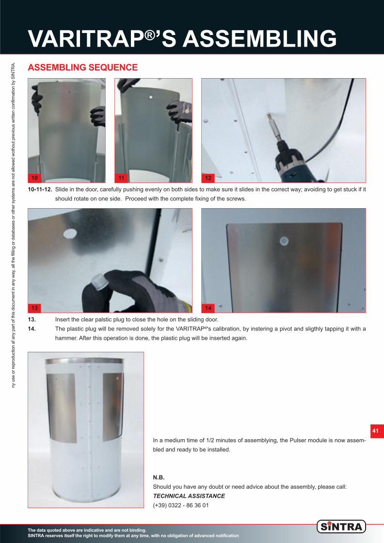
VARITRAP
®
’S ASSEMBLING
The data quoted above are indicative and are not binding.
SINTRA reserves itself the right to modify them at any time, with no obligation of advanced notification
ny use or reproduction af any part of this docum
ent in any w
ay, all the filling or databases or other system
s are not allow
ed w
othout previous w
ritten confirm
ation by S
IN
TR
A.
41
ASSEMBLING SEQUENCE
13. Insert the clear palstic plug to close the hole on the sliding door.
14. The plastic plug will be removed solely for the VARITRAP
®
's calibration, by instering a pivot and sligthly tapping it with a
hammer. After this operation is done, the plastic plug will be inserted again.
10-11-12. Slide in the door, carefully pushing evenly on both sides to make sure it slides in the correct way; avoiding to get stuck if it
should rotate on one side. Proceed with the complete fixing of the screws.
In a medium time of 1/2 minutes of assemblying, the Pulser module is now assem-
bled and ready to be installed.
N.B.
Should you have any doubt or need advice about the assembly, please call:
TECHNICAL ASSISTANCE(+39) 0322 - 86 36 01
10 11 12
13 14
02_Spiropack_ing_v8 ok_Layout 1 24/10/12 17.52 Pagina 41

42
ASSEMBLING OF THE
ADJUSTABLE TELESCOPIC PIECE
The data quoted above are indicative and are not binding.
SINTRA reserves itself the right to modify them at any time, with no obligation of advanced notification
ny use or reproduction af any part of this docum
ent in any w
ay, all the filling or databases or other system
s are not allow
ed w
othout previous w
ritten confirm
ation by S
IN
TR
A.
ASSEMBLING SEQUENCE
1-2. Close with the rivets both the piece with the 8mm folding at both endings, and the “male” piece, with the 8mm folding just on one side.
3. Mark the adjustable piece in the exact point where it will have to
be cut to measure. (The “male” adjustable piece has to enter in
the “female” piece for a length included between 100 mm and
250 mm).
1
3
4. Cut the male piece along the previously marked line.
4
2
02_Spiropack_ing_v8 ok_Layout 1 24/10/12 17.52 Pagina 42
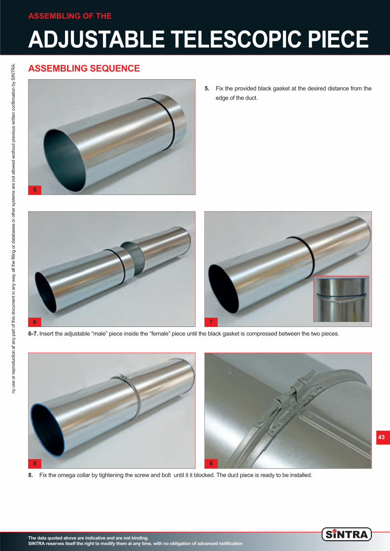
43
ASSEMBLING OF THE
ADJUSTABLE TELESCOPIC PIECE
The data quoted above are indicative and are not binding.
SINTRA reserves itself the right to modify them at any time, with no obligation of advanced notification
ny use or reproduction af any part of this docum
ent in any w
ay, all the filling or databases or other system
s are not allow
ed w
othout previous w
ritten confirm
ation by S
IN
TR
A.
ASSEMBLING SEQUENCE
5. Fix the provided black gasket at the desired distance from the
edge of the duct.
5
6-7. Insert the adjustable “male” piece inside the “female” piece until the black gasket is compressed between the two pieces.
6 7
8. Fix the omega collar by tightening the screw and bolt until it it blocked. The duct piece is ready to be installed.
8 8
02_Spiropack_ing_v8 ok_Layout 1 24/10/12 17.52 Pagina 43

44
FASTENING
The data quoted above are indicative and are not binding.
SINTRA reserves itself the right to modify them at any time, with no obligation of advanced notification
ny use or reproduction af any part of this docum
ent in any w
ay, all the filling or databases or other system
s are not allow
ed w
othout previous w
ritten confirm
ation by S
IN
TR
A.
FASTENING EXAMPLES
For the fastening, SINTRA suggests the use of systems which wrap the duct without blocking it.
SINTRA advises against the fastening on the collar.
For the fixing of the SPIROPACK™ ducts, all the systems normally used to fix circular section ducts can be used, the only required
condition is that the fixing will not obstruct any of the holes, and that it will not be welded or punched into the duct.
We advise against the suspension through the collar’s closing bolt for diameters over 400mm, since the effort which is necessary to
hold the duct up would totally be upon the collar’s welding.
The best solution suggested by SINTRA is to use systems of the “GRIPPLE” kind, with a stainless steel cable which wraps the duct’s
circumference.
02_Spiropack_ing_v8 ok_Layout 1 24/10/12 17.52 Pagina 44

The data quoted above are indicative and are not binding.
SINTRA reserves itself the right to modify them at any time, with no obligation of advanced notification
cop1
Corso Europa 24
28010 Fontaneto d'Agogna (NO)
Tel.: (+39) 0322 863601
Fax: (+39) 0322 863688
Email: sintra@mixind.it
www.mixind.it
02_Spiropack_ing_v8 ok_Layout 1 24/10/12 17.50 Pagina cop1
Top Related