


Languages
Pages
Legal

Usi
ng
01V
96i E
dito
r W
ind
ow
s
1
Get
tin
g S
tart
ed W
ind
ow
sK
eyb
oar
d S
ho
rtcu
tsIn
dex
01V96i Editor—Owner’s Manual
Special Notices
• The software and this owner’s manual are the exclu-sive copyrights of Yamaha Corporation.
• Copying of the software or reproduction of this man-ual in whole or in part by any means is expressly for-bidden without the written consent of the manufacturer.
• Copying of the commercially available music sequence data and/or digital audio files is strictly pro-hibited except for your personal use.
• Yamaha makes no representations or warranties with regard to the use of the software and documentation and cannot be held responsible for the results of the use of this manual and the software.
• The screen displays as illustrated in this owner’s man-ual are for instructional purposes, and may appear somewhat different from the screens which appear on your computer.
• Future upgrades of application and system software and any changes in specifications and functions will be announced separately.
• The company names and product names in this Owner’s Manual are the trademarks or registered trademarks of their respective companies.
Yamaha Pro Audio Global Site
http://www.yamahaproaudio.com/
Contents
Getting Started .......................................... 2Overview of 01V96i Editor .................................... 2Configuring 01V96i Editor .................................... 2Synchronizing 01V96i Editor ................................ 4Offline Edit Function .............................................. 4Working with Sessions ........................................... 4Undo/Redo Function .............................................. 5Other Functions ...................................................... 6
Using 01V96i Editor Windows ................... 7Master Window ....................................................... 7Layer Windows ........................................................ 8Selected Channel Window ................................... 14Library Window .................................................... 21Patch Editor Window ........................................... 23Surround Editor Window .................................... 28Effect Editor Window ........................................... 29Meter Window ...................................................... 31
Keyboard Shortcuts ................................. 32
Index ........................................................ 33
* Specifications and descriptions in this owner ’s manual are for information purposes only. Yamaha Corp. reserves the right to change or modify products or specifications at any time without prior notice. Since specifications, equipment or options may not be the same in every locale, please check with your Yamaha dealer.
01V96i Editor01V96i Editor01V96i EditorOwner’s ManualOwner’s Manual
Description of menus and buttonsIn the event that menu and button names on a Windows system are different from those on a Macintosh, this manual uses the Windows menu and button names followed by the Macintosh menu and button names in parentheses.
Usi
ng
01V
96 E
dito
r W
ind
ow
sG
etti
ng
Sta
rted
Key
bo
ard
Sh
ort
cuts
Ind
ex
201V96i Editor—Owner’s Manual
Win
do
ws
Getting Started
Overview of 01V96i Editor01V96i Editor enables you to remotely control the Yamaha 01V96i mixing console and to save the parameter settings on your computer. To use 01V96i Editor, you must first perform the following operations:
1 Start and configure Studio Manager.
2 Start and configure 01V96i Editor.
3 Synchronize 01V96i Editor with your 01V96i console (see page 4).For more information on using Studio Manager, refer to the Studio Manager Owner’s Manual.
Configuring 01V96i EditorYou must configure the following settings for each open Editor.
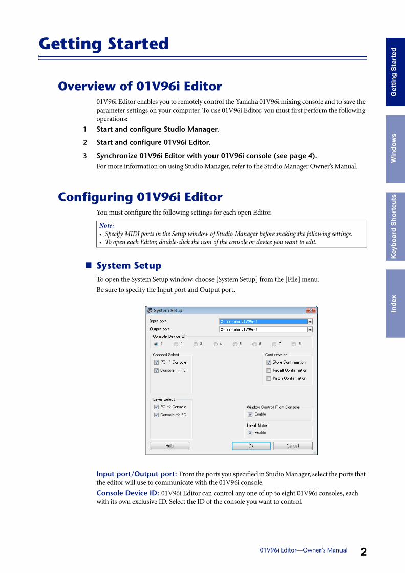
System SetupTo open the System Setup window, choose [System Setup] from the [File] menu. Be sure to specify the Input port and Output port.
Input port/Output port: From the ports you specified in Studio Manager, select the ports that the editor will use to communicate with the 01V96i console.Console Device ID: 01V96i Editor can control any one of up to eight 01V96i consoles, each with its own exclusive ID. Select the ID of the console you want to control.
Note: • Specify MIDI ports in the Setup window of Studio Manager before making the following settings.• To open each Editor, double-click the icon of the console or device you want to edit.
Usi
ng
01V
96 E
dito
r W
ind
ow
sG
etti
ng
Sta
rted
Key
bo
ard
Sh
ort
cuts
Ind
ex
301V96i Editor—Owner’s Manual
Win
do
ws
Channel Select: These options determine whether or not channel selection is linked. When the PC->Console option is on, selecting a channel in 01V96i Editor selects the same channel on the console. When the Console->PC option is on, selecting a channel on the console selects the same channel in 01V96i Editor.Confirmation: These options determine whether or not a confirmation dialog box appears when storing, recalling, or patching.Layer Select: These options determine whether or not Layer selection is linked. When the PC->Console option is on, selecting a Layer in 01V96i Editor selects the same Layer on the console. When the Console->PC option is on, selecting a Layer on the console selects the same Layer in 01V96i Editor.Window Control from Console: This option determines whether or not using the USER DEFINED KEYS on the console enables you to remotely open and close the 01V96i Editor win-dows.Level Meter: This option determines whether or not the level meters in 01V96i Editor are enabled.
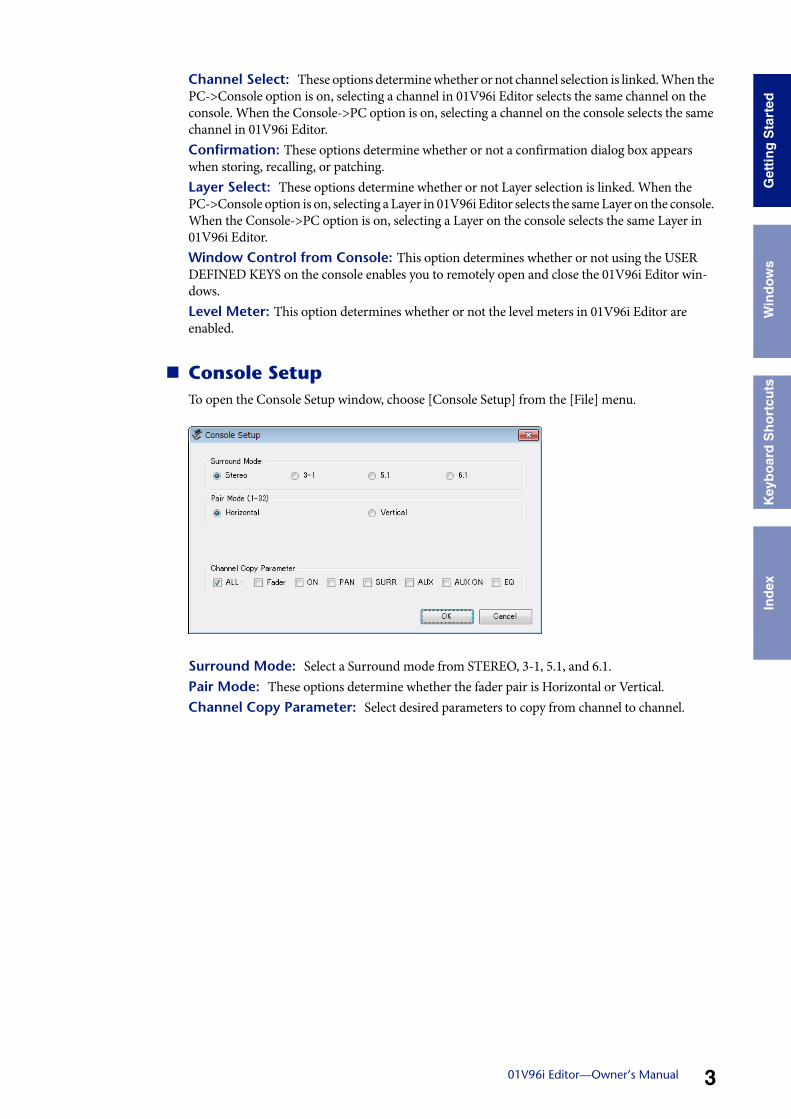
Console SetupTo open the Console Setup window, choose [Console Setup] from the [File] menu.
Surround Mode: Select a Surround mode from STEREO, 3-1, 5.1, and 6.1.Pair Mode: These options determine whether the fader pair is Horizontal or Vertical.Channel Copy Parameter: Select desired parameters to copy from channel to channel.
Usi
ng
01V
96 E
dito
r W
ind
ow
sG
etti
ng
Sta
rted
Key
bo
ard
Sh
ort
cuts
Ind
ex
401V96i Editor—Owner’s Manual
Win
do
ws
Synchronizing 01V96i EditorWhen 01V96i Editor starts up, the parameter settings on the console and the parameter settings in 01V96i Editor may be different. Therefore, you must first match the parameter settings on the con-sole with those in 01V96i Editor. This operation is called “synchronization.” Follow the steps below to synchronize 01V96i Editor.
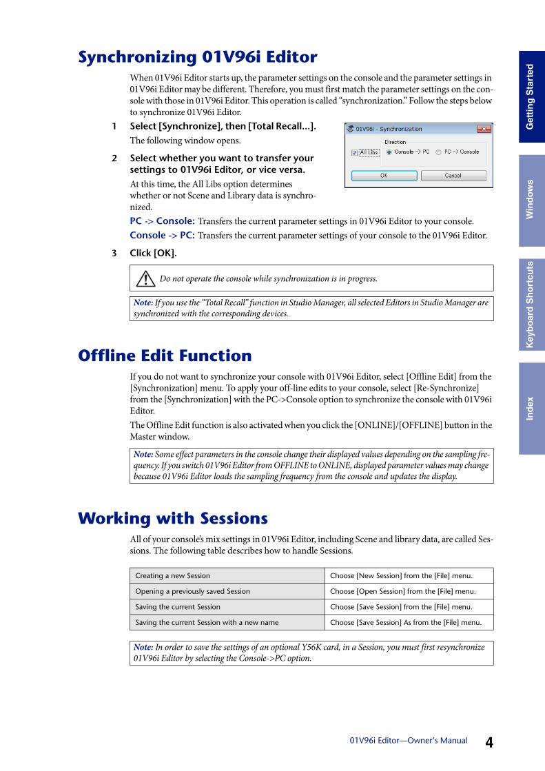
1 Select [Synchronize], then [Total Recall...].The following window opens.
2 Select whether you want to transfer your settings to 01V96i Editor, or vice versa.At this time, the All Libs option determines whether or not Scene and Library data is synchro-nized. PC -> Console: Transfers the current parameter settings in 01V96i Editor to your console.Console -> PC: Transfers the current parameter settings of your console to the 01V96i Editor.
3 Click [OK].
Offline Edit FunctionIf you do not want to synchronize your console with 01V96i Editor, select [Offline Edit] from the [Synchronization] menu. To apply your off-line edits to your console, select [Re-Synchronize] from the [Synchronization] with the PC->Console option to synchronize the console with 01V96i Editor.The Offline Edit function is also activated when you click the [ONLINE]/[OFFLINE] button in the Master window.
Working with SessionsAll of your console’s mix settings in 01V96i Editor, including Scene and library data, are called Ses-sions. The following table describes how to handle Sessions.
Do not operate the console while synchronization is in progress.
Note: If you use the “Total Recall” function in Studio Manager, all selected Editors in Studio Manager are synchronized with the corresponding devices.
Note: Some effect parameters in the console change their displayed values depending on the sampling fre-quency. If you switch 01V96i Editor from OFFLINE to ONLINE, displayed parameter values may change because 01V96i Editor loads the sampling frequency from the console and updates the display.
Creating a new Session Choose [New Session] from the [File] menu.
Opening a previously saved Session Choose [Open Session] from the [File] menu.
Saving the current Session Choose [Save Session] from the [File] menu.
Saving the current Session with a new name Choose [Save Session] As from the [File] menu.
Note: In order to save the settings of an optional Y56K card, in a Session, you must first resynchronize 01V96i Editor by selecting the Console->PC option.
Usi
ng
01V
96 E
dito
r W
ind
ow
sG
etti
ng
Sta
rted
Key
bo
ard
Sh
ort
cuts
Ind
ex
501V96i Editor—Owner’s Manual
Win
do
ws
If you save a Session in an Editor, only that Editor’s settings are saved in a file. The Editor’s settings are saved in either the Studio Manager V2 format (file extension “.YSE”) or a format that is com-patible with earlier versions of Studio Manager (file extension “.01X”). Note that earlier versions of Studio Manager cannot open a Session saved in the “.YSE” format.If you save a Session in the Studio Manager window, all selected Editor settings are saved in a file with a file extension of “.YSM.”
Undo/Redo FunctionIn 01V96i Editor, you can cancel the latest operation (Undo) and also cancel the cancellation of the latest operation (Redo). If you perform an Undo operation twice in a row, you can cancel the two most-recent operations. If you perform an Undo operation three times in a row, you can cancel the three most-recent operations. In this way, you can cancel multiple recent operations. The following table describes how to use the Undo/Redo function.
Please note, however, that after you perform one of the following operations, you cannot success-fully undo or redo any previous operation:• Operations on the console• Closing Studio Manager• Changing Surround mode (Stereo/3-1/5.1/6.1)• Changing Pair mode (Horizontal/vertical)• Synchronizing the console with 01V96i Editor• Creating a new Session• Saving a Session• Copying and pasting a channel• Creating or cancelling a channel pair• Storing or recalling a scene or library• Turning on or off the GATE: [LINK] button in the Selected Channel window• Turning on or off the COMPRESSOR: [LINK] button in the Selected Channel window• Turning on or off the [LINK] button in the Surround Editor window• Changing Aux Send mode (Fixed/variable) on the console• Changing the sampling frequency (operated on the device)• Changing the User Assignable Layer settings (operated on the device)
Undo Choose [Undo] from the [Edit] menu.
Redo Choose [Redo] from the [Edit] menu.
Note: You cannot Undo or Redo the following operations:• Edits in the Setup window• Synchronization• Opening and closing the windows• Resizing the windows
Note: In the Library window, you can Undo or Redo only the most recent operation. You cannot cancel the preceding operations.
Usi
ng
01V
96 E
dito
r W
ind
ow
sG
etti
ng
Sta
rted
Key
bo
ard
Sh
ort
cuts
Ind
ex
601V96i Editor—Owner’s Manual
Win
do
ws
Other Functions
Copy & Paste FunctionYou can copy and paste the channel parameters.In the Console Setup window (page 3), you can also specify the parameters to be copied.The following table describes how to use the Copy & Paste function.
Resetting to the default value (Ctrl ( ) + click)Move the cursor to a control or a parameter value, then hold down the <Ctrl> key ( ) and click the mouse button to reset the value to the default (e.g., to reset an Input Channel fader to –×, or reset a pan setting to Center).
Ctrl( )+Shift+ClickMove the cursor to a fader or AUX Send control, then hold down the <Ctrl> key ([ ]) and <Shift> key and click the mouse button to reset the value to the nominal level.
Copying a channel Right-click (<control>+click) a copy source channel, then choose [Copy].
Pasting a channelRight-click (<control>+click) the copy destination channel, then choose [Paste].
701V96i Editor—Owner’s Manual
Get
ting
Sta
rted
Key
boar
d S
hort
cuts
Inde
x W
indo
ws
Using 01V96i Editor Windows
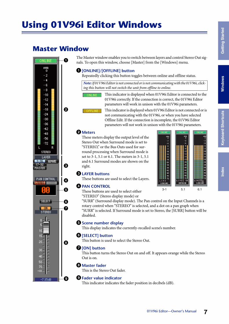
Master WindowThe Master window enables you to switch between layers and control Stereo Out sig-nals. To open this window, choose [Master] from the [Windows] menu.
1 [ONLINE]/[OFFLINE] buttonRepeatedly clicking this button toggles between online and offline status.
This indicator is displayed when 01V96i Editor is connected to the 01V96i correctly. If the connection is correct, the 01V96i Editor parameters will work in unison with the 01V96i parameters.This indicator is displayed when 01V96i Editor is not connected or is not communicating with the 01V96i, or when you have selected Offline Edit. If the connection is incomplete, the 01V96i Editor parameters will not work in unison with the 01V96i parameters.
2MetersThese meters display the output level of the Stereo Out when Surround mode is set to “STEREO,” or the Bus Outs used for sur-round processing when Surround mode is set to 3-1, 5.1 or 6.1. The meters in 3-1, 5.1 and 6.1 Surround modes are shown on the right.
3 LAYER buttonsThese buttons are used to select the Layers.
4 PAN CONTROLThese buttons are used to select either “STEREO” (Stereo display mode) or “SURR” (Surround display mode). The Pan control on the Input Channels is a rotary control when “STEREO” is selected, and a dot on a pan graph when “SURR” is selected. If Surround mode is set to Stereo, the [SURR] button will be disabled.
5 Scene number displayThis display indicates the currently-recalled scene’s number.
6 [SELECT] buttonThis button is used to select the Stereo Out.
7 [ON] buttonThis button turns the Stereo Out on and off. It appears orange while the Stereo Out is on.
8Master faderThis is the Stereo Out fader.
9 Fader value indicatorThis indicator indicates the fader position in decibels (dB).
Note: If 01V96i Editor is not connected or is not communicating with the 01V96i, click-ing this button will not switch the unit from offline to online.
2
1
3
4
5
6
7
8
9
3-1 5.1 6.1
Usi
ng 0
1V96
Edi
tor
Win
dow
sG
ettin
g S
tart
edK
eybo
ard
Sho
rtcu
tsIn
dex
801V96i Editor—Owner’s Manual
Win
dow
s
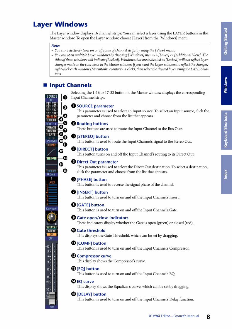
Layer WindowsThe Layer window displays 16 channel strips. You can select a layer using the LAYER buttons in the Master window. To open the Layer window, choose [Layer] from the [Windows] menu.
Input ChannelsSelecting the 1-16 or 17-32 button in the Master window displays the corresponding Input Channel strips.
1 SOURCE parameterThis parameter is used to select an Input source. To select an Input source, click the parameter and choose from the list that appears.
2 Routing buttonsThese buttons are used to route the Input Channel to the Bus Outs.
3 [STEREO] buttonThis button is used to route the Input Channel’s signal to the Stereo Out.
4 [DIRECT] buttonThis button turns on and off the Input Channel’s routing to its Direct Out.
5Direct Out parameterThis parameter is used to select the Direct Out destination. To select a destination, click the parameter and choose from the list that appears.
6 [PHASE] buttonThis button is used to reverse the signal phase of the channel.
7 [INSERT] buttonThis button is used to turn on and off the Input Channel’s Insert.
8 [GATE] buttonThis button is used to turn on and off the Input Channel’s Gate.
9Gate open/close indicatorsThese indicators display whether the Gate is open (green) or closed (red).
)Gate thresholdThis displays the Gate Threshold, which can be set by dragging.
! [COMP] buttonThis button is used to turn on and off the Input Channel’s Compressor.
@ Compressor curveThis display shows the Compressor’s curve.
# [EQ] buttonThis button is used to turn on and off the Input Channel’s EQ.
$ EQ curveThis display shows the Equalizer’s curve, which can be set by dragging.
% [DELAY] buttonThis button is used to turn on and off the Input Channel’s Delay function.
Note: • You can selectively turn on or off some of channel strips by using the [View] menu.• You can open multiple Layer windows by choosing [Windows] menu -> [Layer] -> [Additional View]. The
titles of these windows will indicate [Locked]. Windows that are indicated as [Locked] will not reflect layer changes made on the console or in the Master window. If you want the Layer windows to reflect the changes, right-click each window (Macintosh: <control> + click), then select the desired layer using the LAYER but-tons.
1
2
3456789)!
@
#
$
%
Usi
ng 0
1V96
Edi
tor
Win
dow
sG
ettin
g S
tart
edK
eybo
ard
Sho
rtcu
tsIn
dex
901V96i Editor—Owner’s Manual
Win
dow
s
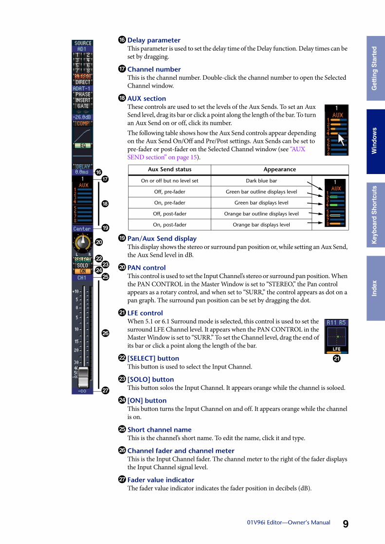
^Delay parameterThis parameter is used to set the delay time of the Delay function. Delay times can be set by dragging.
& Channel numberThis is the channel number. Double-click the channel number to open the Selected Channel window.
* AUX sectionThese controls are used to set the levels of the Aux Sends. To set an Aux Send level, drag its bar or click a point along the length of the bar. To turn an Aux Send on or off, click its number.The following table shows how the Aux Send controls appear depending on the Aux Send On/Off and Pre/Post settings. Aux Sends can be set to pre-fader or post-fader on the Selected Channel window (see “AUX SEND section” on page 15).
( Pan/Aux Send displayThis display shows the stereo or surround pan position or, while setting an Aux Send, the Aux Send level in dB.
A PAN controlThis control is used to set the Input Channel’s stereo or surround pan position. When the PAN CONTROL in the Master Window is set to “STEREO,” the Pan control appears as a rotary control, and when set to “SURR,” the control appears as dot on a pan graph. The surround pan position can be set by dragging the dot.
B LFE controlWhen 5.1 or 6.1 Surround mode is selected, this control is used to set the surround LFE Channel level. It appears when the PAN CONTROL in the Master Window is set to “SURR.” To set the Channel level, drag the end of its bar or click a point along the length of the bar.
C [SELECT] buttonThis button is used to select the Input Channel.
D [SOLO] buttonThis button solos the Input Channel. It appears orange while the channel is soloed.
E [ON] buttonThis button turns the Input Channel on and off. It appears orange while the channel is on.
F Short channel nameThis is the channel’s short name. To edit the name, click it and type.
G Channel fader and channel meterThis is the Input Channel fader. The channel meter to the right of the fader displays the Input Channel signal level.
H Fader value indicatorThe fader value indicator indicates the fader position in decibels (dB).
^&
*
(
A
CDEF
G
H
Aux Send status Appearance
On or off but no level set Dark blue bar
Off, pre-fader Green bar outline displays level
On, pre-fader Green bar displays level
Off, post-fader Orange bar outline displays level
On, post-fader Orange bar displays level
B
Usi
ng 0
1V96
Edi
tor
Win
dow
sG
ettin
g S
tart
edK
eybo
ard
Sho
rtcu
tsIn
dex
1001V96i Editor—Owner’s Manual
Win
dow
s
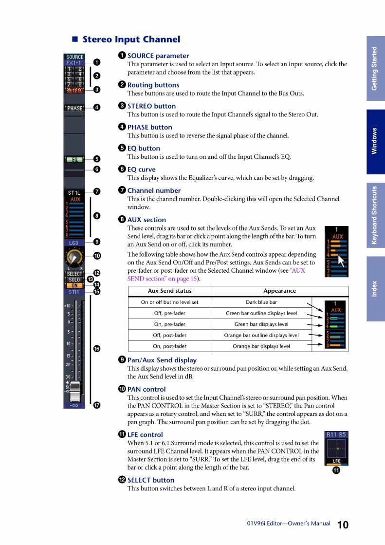
Stereo Input Channel
1 SOURCE parameterThis parameter is used to select an Input source. To select an Input source, click the parameter and choose from the list that appears.
2 Routing buttonsThese buttons are used to route the Input Channel to the Bus Outs.
3 STEREO buttonThis button is used to route the Input Channel’s signal to the Stereo Out.
4 PHASE buttonThis button is used to reverse the signal phase of the channel.
5 EQ buttonThis button is used to turn on and off the Input Channel’s EQ.
6 EQ curveThis display shows the Equalizer’s curve, which can be set by dragging.
7 Channel numberThis is the channel number. Double-clicking this will open the Selected Channel window.
8 AUX sectionThese controls are used to set the levels of the Aux Sends. To set an Aux Send level, drag its bar or click a point along the length of the bar. To turn an Aux Send on or off, click its number.The following table shows how the Aux Send controls appear depending on the Aux Send On/Off and Pre/Post settings. Aux Sends can be set to pre-fader or post-fader on the Selected Channel window (see “AUX SEND section” on page 15).
9 Pan/Aux Send displayThis display shows the stereo or surround pan position or, while setting an Aux Send, the Aux Send level in dB.
) PAN controlThis control is used to set the Input Channel’s stereo or surround pan position. When the PAN CONTROL in the Master Section is set to “STEREO,” the Pan control appears as a rotary control, and when set to “SURR,” the control appears as dot on a pan graph. The surround pan position can be set by dragging the dot.
! LFE controlWhen 5.1 or 6.1 Surround mode is selected, this control is used to set the surround LFE Channel level. It appears when the PAN CONTROL in the Master Section is set to “SURR.” To set the LFE level, drag the end of its bar or click a point along the length of the bar.
@ SELECT buttonThis button switches between L and R of a stereo input channel.
7
1
2
3
4
5
9
6
@
%
&
^
#
8
)
$Aux Send status Appearance
On or off but no level set Dark blue bar
Off, pre-fader Green bar outline displays level
On, pre-fader Green bar displays level
Off, post-fader Orange bar outline displays level
On, post-fader Orange bar displays level
!

Usi
ng 0
1V96
Edi
tor
Win
dow
sG
ettin
g S
tart
edK
eybo
ard
Sho
rtcu
tsIn
dex
1101V96i Editor—Owner’s Manual
Win
dow
s
# SOLO buttonThis button solos the Input Channel. It appears orange while the channel is soloed.
$ON buttonThis button turns the Input Channel on and off. It appears orange while the channel is on.
% Short channel nameThis is the channel’s short name. To edit the name, click it and type.
^ Channel fader/Channel meterThis is the Input Channel’s fader. The meter at the right of the fader indicates the sig-nal level.
& Fader valueThis indicates the dB value of the fader.
1201V96i Editor—Owner’s Manual
Get
ting
Sta
rted
Key
boar
d S
hort
cuts
Inde
x W
indo
ws
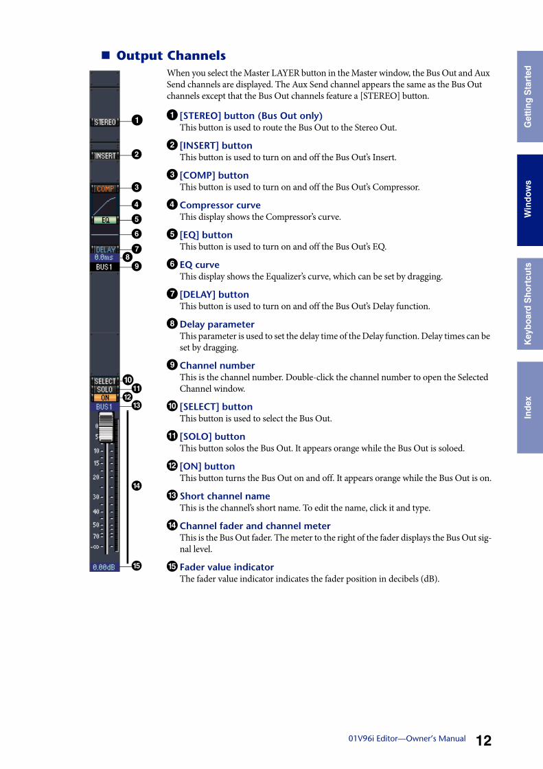
Output ChannelsWhen you select the Master LAYER button in the Master window, the Bus Out and Aux Send channels are displayed. The Aux Send channel appears the same as the Bus Out channels except that the Bus Out channels feature a [STEREO] button.
1 [STEREO] button (Bus Out only)This button is used to route the Bus Out to the Stereo Out.
2 [INSERT] buttonThis button is used to turn on and off the Bus Out’s Insert.
3 [COMP] buttonThis button is used to turn on and off the Bus Out’s Compressor.
4 Compressor curveThis display shows the Compressor’s curve.
5 [EQ] buttonThis button is used to turn on and off the Bus Out’s EQ.
6 EQ curveThis display shows the Equalizer’s curve, which can be set by dragging.
7 [DELAY] buttonThis button is used to turn on and off the Bus Out’s Delay function.
8Delay parameterThis parameter is used to set the delay time of the Delay function. Delay times can be set by dragging.
9 Channel numberThis is the channel number. Double-click the channel number to open the Selected Channel window.
) [SELECT] buttonThis button is used to select the Bus Out.
! [SOLO] buttonThis button solos the Bus Out. It appears orange while the Bus Out is soloed.
@ [ON] buttonThis button turns the Bus Out on and off. It appears orange while the Bus Out is on.
# Short channel nameThis is the channel’s short name. To edit the name, click it and type.
$ Channel fader and channel meterThis is the Bus Out fader. The meter to the right of the fader displays the Bus Out sig-nal level.
% Fader value indicatorThe fader value indicator indicates the fader position in decibels (dB).
78
1
2
3
4
5
9
6
!
#
%
$
)
@
1301V96i Editor—Owner’s Manual
Get
ting
Sta
rted
Key
boar
d S
hort
cuts
Inde
x W
indo
ws
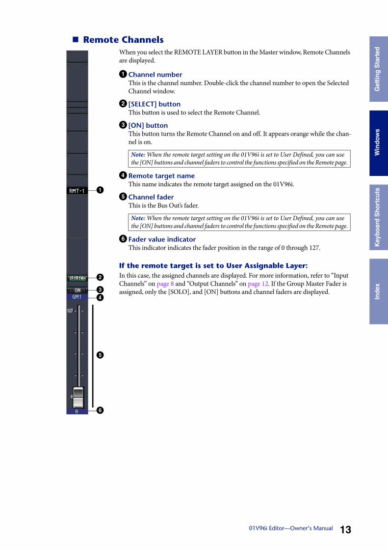
Remote ChannelsWhen you select the REMOTE LAYER button in the Master window, Remote Channels are displayed.
1 Channel numberThis is the channel number. Double-click the channel number to open the Selected Channel window.
2 [SELECT] buttonThis button is used to select the Remote Channel.
3 [ON] buttonThis button turns the Remote Channel on and off. It appears orange while the chan-nel is on.
4 Remote target nameThis name indicates the remote target assigned on the 01V96i.
5 Channel faderThis is the Bus Out’s fader.
6 Fader value indicatorThis indicator indicates the fader position in the range of 0 through 127.
If the remote target is set to User Assignable Layer:In this case, the assigned channels are displayed. For more information, refer to “Input Channels” on page 8 and “Output Channels” on page 12. If the Group Master Fader is assigned, only the [SOLO], and [ON] buttons and channel faders are displayed.
Note: When the remote target setting on the 01V96i is set to User Defined, you can use the [ON] buttons and channel faders to control the functions specified on the Remote page.
Note: When the remote target setting on the 01V96i is set to User Defined, you can use the [ON] buttons and channel faders to control the functions specified on the Remote page.
1
2
34
6
5
Usi
ng 0
1V96
Edi
tor
Win
dow
sG
ettin
g S
tart
edK
eybo
ard
Sho
rtcu
tsIn
dex
1401V96i Editor—Owner’s Manual
Win
dow
s
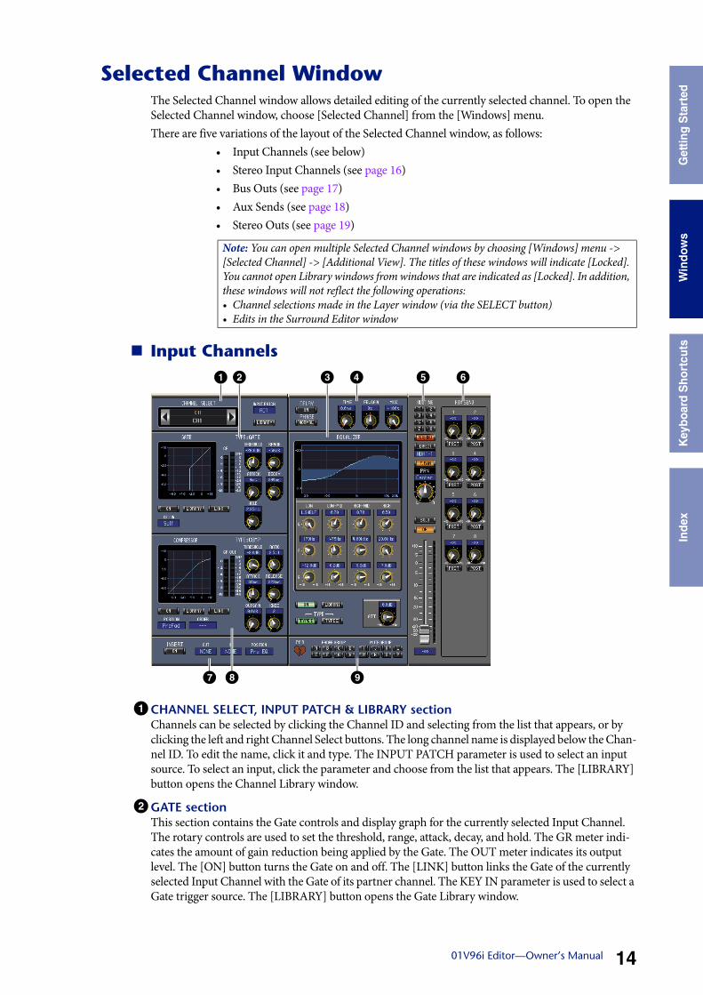
Selected Channel WindowThe Selected Channel window allows detailed editing of the currently selected channel. To open the Selected Channel window, choose [Selected Channel] from the [Windows] menu.There are five variations of the layout of the Selected Channel window, as follows:
• Input Channels (see below)• Stereo Input Channels (see page 16)• Bus Outs (see page 17)• Aux Sends (see page 18)• Stereo Outs (see page 19)
Input Channels
1 CHANNEL SELECT, INPUT PATCH & LIBRARY sectionChannels can be selected by clicking the Channel ID and selecting from the list that appears, or by clicking the left and right Channel Select buttons. The long channel name is displayed below the Chan-nel ID. To edit the name, click it and type. The INPUT PATCH parameter is used to select an input source. To select an input, click the parameter and choose from the list that appears. The [LIBRARY] button opens the Channel Library window.
2GATE sectionThis section contains the Gate controls and display graph for the currently selected Input Channel. The rotary controls are used to set the threshold, range, attack, decay, and hold. The GR meter indi-cates the amount of gain reduction being applied by the Gate. The OUT meter indicates its output level. The [ON] button turns the Gate on and off. The [LINK] button links the Gate of the currently selected Input Channel with the Gate of its partner channel. The KEY IN parameter is used to select a Gate trigger source. The [LIBRARY] button opens the Gate Library window.
Note: You can open multiple Selected Channel windows by choosing [Windows] menu -> [Selected Channel] -> [Additional View]. The titles of these windows will indicate [Locked]. You cannot open Library windows from windows that are indicated as [Locked]. In addition, these windows will not reflect the following operations:• Channel selections made in the Layer window (via the SELECT button)• Edits in the Surround Editor window
1 2 43 5 6
7 8 9
Usi
ng 0
1V96
Edi
tor
Win
dow
sG
ettin
g S
tart
edK
eybo
ard
Sho
rtcu
tsIn
dex
1501V96i Editor—Owner’s Manual
Win
dow
s
3 EQUALIZER sectionThis section contains the EQ controls and display graph for the currently selected Input Channel. The rotary controls are used to set the gain, center frequency, and Q of each band, and the pre-EQ attenuation level. EQ can also be set by dragging the EQ curve on the EQUALIZER graph. The [ON] button turns the EQ on and off. The TYPE buttons select the EQ type. The [LIBRARY] button opens the Equalizer Library window.
4DELAY & PHASE sectionThis section contains the delay and phase controls for the currently selected Input Channel. The rotary controls are used to set the delay time, feedback gain, and mix balance (wet/dry balance). The [ON] button turns the Delay on and off. The [PHASE] button reverses the channel’s signal phase.
5 ROUTING, PAN & level sectionThis section contains the routing, pan, and level controls and the [SOLO], and [ON] buttons for the currently selected Input Channel. ROUTING buttons 1–8 are used to route the channel to the Bus Outs. The [STEREO] button routes the channel to the Stereo Out. The [DIRECT] button routes the channel to its Direct Out, and the Direct Out parameter below it selects a Direct Out destination. The [F.PAN] button turns on and off the Bus Out Follow Pan function. The PAN control is used to pan the channel. The [SOLO] button is used to solo the channel, the [ON] button, to turn on and off the chan-nel, and the channel fader, to set the channel level. The meter to the right of the fader indicates the sig-nal level, and the value indicator under the fader indicates the fader position in decibels (dB).
6 AUX SEND sectionThis section contains the Aux Send controls for the currently selected Input Channel. Use the rotary controls to set the Aux Send levels, and click them to turn Aux Sends on and off. Use the button below each Aux Send control to select pre-fader or post-fader. In Fixed mode, this button is used to turn Aux Sends on and off (the level is fixed at nominal).When Aux Sends are paired, a heart icon is displayed between them, and the odd-numbered Aux Send control sets the level, while the even-numbered control works as a pan control.
7 INSERT sectionThis section contains the Insert parameters for the currently selected Input Channel. The [ON] button turns the Insert on and off. The OUT and IN parameters are used to specify the insert out destination and insert in source respectively. The POSITION parameter is used to specify the position of the Insert in the signal path.
8 COMPRESSOR sectionThis section contains the Compressor controls and display graph for the currently selected Input Channel. The rotary controls are used to set the threshold, ratio, attack, release, gain, and knee. The GR meter indicates the amount of gain reduction being applied by the Compressor. The OUT meter indicates its output level. The [ON] button turns the Compressor on and off. The [LINK] button links the Compressor of the currently selected Input Channel with the Compressor of its partner channel. The POSITION parameter is used to specify the position of the Compressor in the signal path. The ORDER parameter is used to specify the order of the Compressor and Insert when both are inserted at the same position. The [LIBRARY] button opens the Compressor Library window.
9 PAIR, FADER GROUP & MUTE GROUP sectionThis section contains the Pair, Fader and Mute group functions for the currently selected Input Channel. Click the heart icon to pair and unpair the channel with its partner chan-nel. Use the FADER GROUP buttons to add the channel to Fader groups, and use the MUTE GROUP buttons to add it to Mute groups.
Usi
ng 0
1V96
Edi
tor
Win
dow
sG
ettin
g S
tart
edK
eybo
ard
Sho
rtcu
tsIn
dex
1601V96i Editor—Owner’s Manual
Win
dow
s
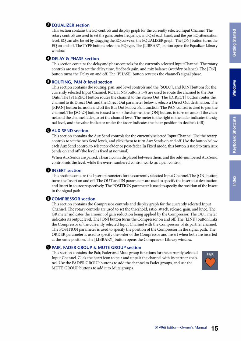
Stereo Input Channels
1 CHANNEL SELECT, INPUT PATCH & LIBRARY sectionChannels can be selected by clicking the Channel ID and selecting from the list that appears, or by clicking the left and right Channel Select buttons. The long channel name is displayed below the Chan-nel ID. To edit the name, click it and type. The INPUT PATCH parameter is used to select an input source. To select an input, click the parameter and choose from the list that appears. The LIBRARY button opens the Channel Library window.
2 PHASE sectionThis section contains the phase control for the currently selected Stereo Input Channel. The PHASE button reverses the channel’s signal phase.
3 EQUALIZER sectionThis section contains the EQ controls and display graph for the currently selected Stereo Input Chan-nel. The rotary controls are used to set the gain, center frequency, and Q of each band, and the pre-EQ attenuation level. EQ can also be set by dragging the EQ curve on the EQUALIZER graph. The ON button turns the EQ on and off. The TYPE buttons select the EQ type. The LIBRARY button opens the Equalizer Library window.
4 Routing, pan & level sectionThis section contains the routing, pan, and level controls and the, SOLO, and ON buttons for the cur-rently selected Stereo Input Channel. ROUTING buttons 1–8 are used to route the channel to the Bus Outs. The STEREO button routes the channel to the Stereo Out. The DIRECT button routes the chan-nel to its Direct Out, and the Direct Out parameter below it selects a Direct Out destination. The F.PAN button turns on and off the Bus Out Follow Pan function. The PAN control is used to pan the channel. The SOLO button is used to solo the channel, the ON button, to turn on and off the channel, and the channel fader, to set the channel level.
5 AUX SEND sectionThis section contains the Aux Send controls for the currently selected Stereo Input Channel. Use the rotary controls to set the Aux Send levels, and click them to turn Aux Sends on and off. Use the button below each Aux Send control to select pre-fader or post-fader. In Fixed mode, this button is used to turn Aux Sends on and off (the level is fixed at nominal).When Aux Sends are paired, a heart icon is displayed between them, and the odd-numbered Aux Send control sets the level, while the even-numbered control works as a pan control.
1 2 3 4
6
5
Usi
ng 0
1V96
Edi
tor
Win
dow
sG
ettin
g S
tart
edK
eybo
ard
Sho
rtcu
tsIn
dex
1701V96i Editor—Owner’s Manual
Win
dow
s
6 FADER GROUP & MUTE GROUP sectionThis section contains the Fader and Mute group functions for the currently selected Stereo Input Channel. Use the FADER GROUP buttons to add the channel to Fader groups, and use the MUTE GROUP buttons to add it to Mute groups.
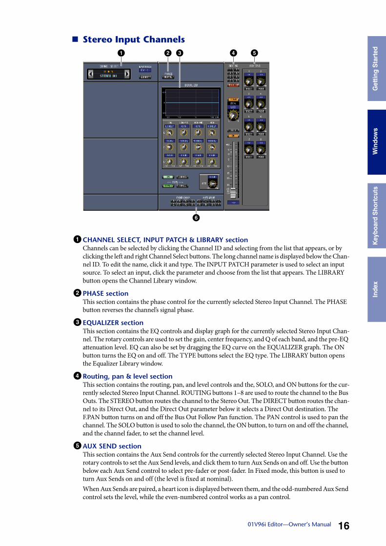
Bus Outs
1 CHANNEL SELECT sectionChannels can be selected by clicking the Channel ID and selecting from the list that appears, or by clicking the left and right Channel Select buttons. The long channel name is displayed below the Chan-nel ID. The [LIBRARY] button opens the Channel Library window.
2 EQUALIZER sectionThis section contains the EQ controls and display graph for the currently selected Bus Out. It’s layout is identical to the EQUALIZER section for Input Channels. See “EQUALIZER section” on page 15 for more information.
3DELAY sectionThis section contains the delay controls for the currently selected Bus Out. The rotary control is used to set the delay time, and the [ON] button turns the Delay function on and off.
4 TO STEREO & level sectionThis section contains the TO STEREO, pan and level controls and the [SOLO], and [ON] buttons for the currently selected Bus Out. The TO STEREO button routes the Bus Out to the Stereo Out, and the rotary controls are used to set the Bus to Stereo send level and pan. The [SOLO] button is used to solo the Bus Out, the [ON] button, to turn the Bus Out on and off, and the channel fader, to set the Bus Out level. The meter to the right of the fader indicates the signal level, and the value indicator under the fader indicates the fader position in dB.
5 INSERT sectionThis section contains the Insert parameters for the currently selected Bus Out. The [ON] button turns the Insert on and off. The OUT and IN parameters are used to select the insert out destination and insert in source respectively. The POSITION parameter is used to specify the position of the Insert in the signal path.
1 32 4
5 6 7
Usi
ng 0
1V96
Edi
tor
Win
dow
sG
ettin
g S
tart
edK
eybo
ard
Sho
rtcu
tsIn
dex
1801V96i Editor—Owner’s Manual
Win
dow
s
6 COMPRESSOR sectionThis section contains the Compressor controls and display graph for the currently selected Bus Out. Its layout is identical to the COMPRESSOR section for Input Channels. See “COMPRESSOR section” on page 15 for more information.
7 PAIR, FADER GROUP & MUTE GROUP sectionThis section contains the Pair, Fader and Mute group functions for the currently selected Bus Out. Click the heart icon to pair and unpair the channel with its partner channel. Use the FADER GROUP buttons to add the channel to Fader groups, and use the MUTE GROUP buttons to add it to Mute groups.
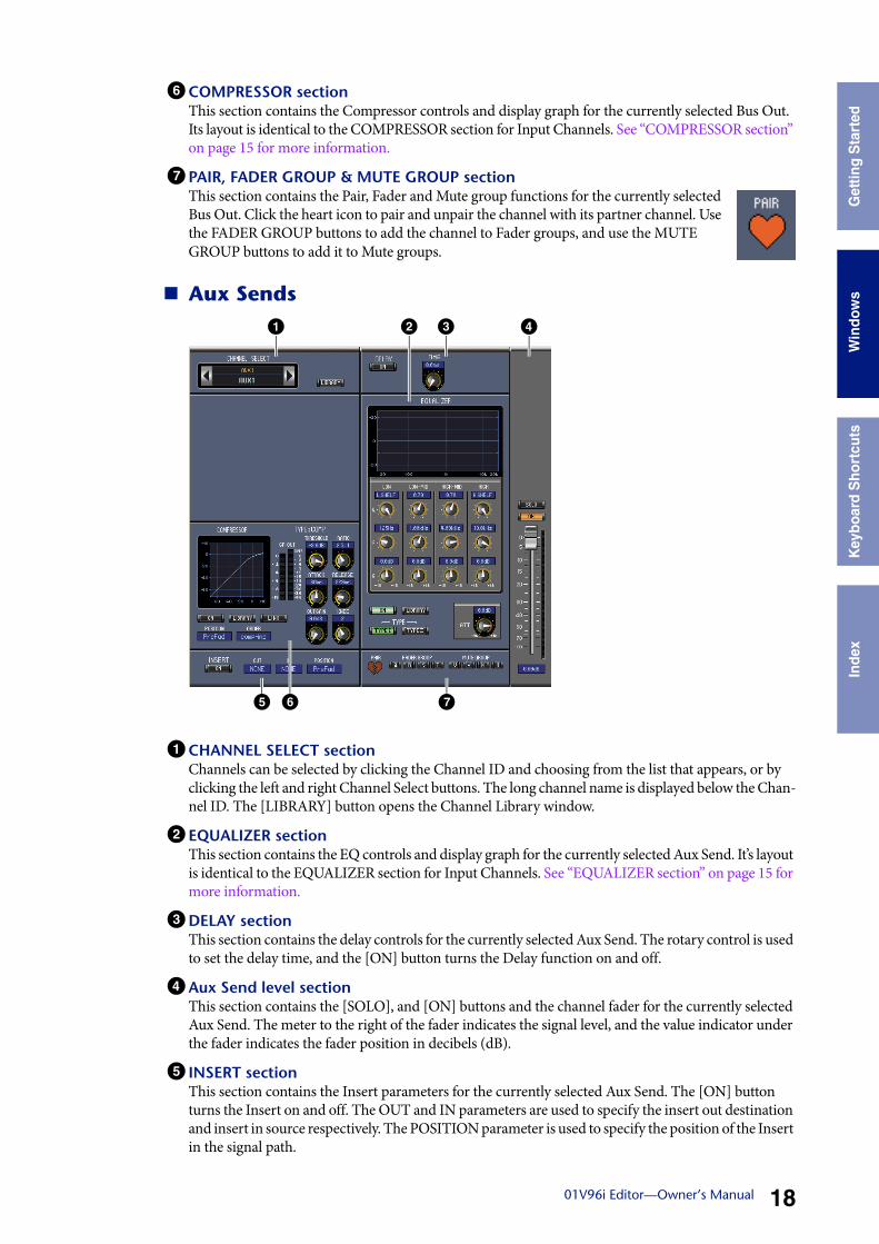
Aux Sends
1 CHANNEL SELECT sectionChannels can be selected by clicking the Channel ID and choosing from the list that appears, or by clicking the left and right Channel Select buttons. The long channel name is displayed below the Chan-nel ID. The [LIBRARY] button opens the Channel Library window.
2 EQUALIZER sectionThis section contains the EQ controls and display graph for the currently selected Aux Send. It’s layout is identical to the EQUALIZER section for Input Channels. See “EQUALIZER section” on page 15 for more information.
3DELAY sectionThis section contains the delay controls for the currently selected Aux Send. The rotary control is used to set the delay time, and the [ON] button turns the Delay function on and off.
4 Aux Send level sectionThis section contains the [SOLO], and [ON] buttons and the channel fader for the currently selected Aux Send. The meter to the right of the fader indicates the signal level, and the value indicator under the fader indicates the fader position in decibels (dB).
5 INSERT sectionThis section contains the Insert parameters for the currently selected Aux Send. The [ON] button turns the Insert on and off. The OUT and IN parameters are used to specify the insert out destination and insert in source respectively. The POSITION parameter is used to specify the position of the Insert in the signal path.
1 32 4
5 6 7

Usi
ng 0
1V96
Edi
tor
Win
dow
sG
ettin
g S
tart
edK
eybo
ard
Sho
rtcu
tsIn
dex
1901V96i Editor—Owner’s Manual
Win
dow
s
6 COMPRESSOR sectionThis section contains the Compressor controls and display graph for the currently selected Aux Send. Its layout is identical to the COMPRESSOR section for Input Channels. See “COMPRESSOR section” on page 15 for more information.
7 PAIR, FADER GROUP & MUTE GROUP sectionThis section contains the Pair, Fader and Mute group functions for the currently selected Aux Send. Click the heart icon to pair and unpair the channel with its partner channel. Use the FADER GROUP buttons to add the channel to Fader groups, and use the MUTE GROUP buttons to add it to Mute groups.
Stereo Out
1 CHANNEL SELECT sectionChannels can be selected by clicking the Channel ID and choosing from the list that appears, or by clicking the left and right Channel Select buttons. The long channel name is displayed below the Chan-nel ID. The [LIBRARY] button opens the Channel Library window.
2 EQUALIZER sectionThis section contains the EQ controls and display graph for the Stereo Out. It’s layout is identical to the EQUALIZER section for Input Channels. See “EQUALIZER section” on page 15 for more informa-tion.
3DELAY sectionThis section contains the delay controls for the Stereo Out. The rotary control is used to set the delay time, and the [ON] button turns the Delay function on and off.
4 Balance & level sectionThis section contains the balance control, [ON], and channel fader for the Stereo Out. The meter to the right of the fader indicates the signal level, and the value indicator under the fader indicates the fader position in decibels (dB).
5 INSERT sectionThis section contains the Insert parameters for the Stereo Out. The [ON] button turns the Insert on and off. The OUT and IN parameters are used to specify the insert out destination and insert in source respectively. The POSITION parameter is used to specify the position of the Insert in the signal path.
1 32 4
5 6 7
Usi
ng 0
1V96
Edi
tor
Win
dow
sG
ettin
g S
tart
edK
eybo
ard
Sho
rtcu
tsIn
dex
2001V96i Editor—Owner’s Manual
Win
dow
s
6 COMPRESSOR sectionThis section contains the Compressor controls and display graph for the currently selected Stereo Out. Its layout is identical to the COMPRESSOR section for Input Channels except there is no [LINK] but-ton. See “COMPRESSOR section” on page 15 for more information.
7 FADER GROUP & MUTE GROUP sectionThis section contains the Fader and Mute group functions for the Stereo Out. Use the FADER GROUP buttons to add the Stereo Out to Fader groups, and use the MUTE GROUP buttons to add it to Mute groups.
Usi
ng 0
1V96
Edi
tor
Win
dow
sG
ettin
g S
tart
edK
eybo
ard
Sho
rtcu
tsIn
dex
2101V96i Editor—Owner’s Manual
Win
dow
s
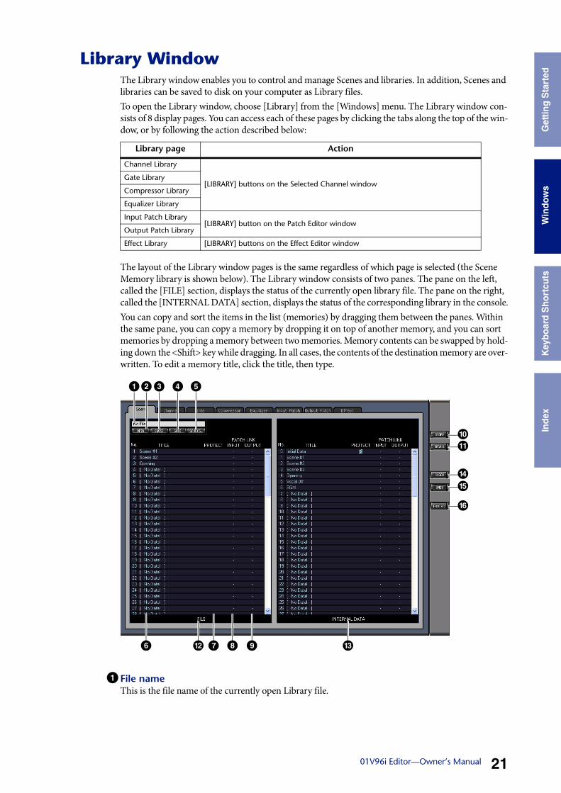
Library WindowThe Library window enables you to control and manage Scenes and libraries. In addition, Scenes and libraries can be saved to disk on your computer as Library files.To open the Library window, choose [Library] from the [Windows] menu. The Library window con-sists of 8 display pages. You can access each of these pages by clicking the tabs along the top of the win-dow, or by following the action described below:
The layout of the Library window pages is the same regardless of which page is selected (the Scene Memory library is shown below). The Library window consists of two panes. The pane on the left, called the [FILE] section, displays the status of the currently open library file. The pane on the right, called the [INTERNAL DATA] section, displays the status of the corresponding library in the console.You can copy and sort the items in the list (memories) by dragging them between the panes. Within the same pane, you can copy a memory by dropping it on top of another memory, and you can sort memories by dropping a memory between two memories. Memory contents can be swapped by hold-ing down the <Shift> key while dragging. In all cases, the contents of the destination memory are over-written. To edit a memory title, click the title, then type.
1 File nameThis is the file name of the currently open Library file.
Library page Action
Channel Library
[LIBRARY] buttons on the Selected Channel windowGate Library
Compressor Library
Equalizer Library
Input Patch Library[LIBRARY] button on the Patch Editor window
Output Patch Library
Effect Library [LIBRARY] buttons on the Effect Editor window
1
6
23 4 5
7 8 9@ #
)!
$%
^
Usi
ng 0
1V96
Edi
tor
Win
dow
sG
ettin
g S
tart
edK
eybo
ard
Sho
rtcu
tsIn
dex
2201V96i Editor—Owner’s Manual
Win
dow
s
2 [OPEN] buttonThis button is used to open Library files.
3 [CLOSE] buttonThis button is used to close the currently open Library file.
4 [SAVE] buttonThis button is used to save the currently open Library file.
5 [SAVE AS] buttonThis button is used to save the currently open Library file with a different name.
6 TITLEThis column displays the memory titles.
7 PROTECT (only for Scene memories)This column displays padlock icons for protected memories. It also displays an “ ” (read-only) icon for preset data.
8 INPUT PATCH LINK (only for Scene memories)This column displays the input patch memory numbers linked to the Scene library. When you store or recall a Scene memory, the linked Input Patch Library memory is stored or recalled at the same time.
9OUTPUT PATCH LINK (only for Scene memories)This column displays the Output Patch memory numbers linked to the Scene library. When you store or recall a Scene memory, the linked Output Patch Library memory is stored or recalled at the same time.
) [STORE] buttonThis button is used to store the contents of the library to the specified location.
! [RECALL] buttonThis button is used to recall the selected memory.
@ [FILE] sectionThis section displays the contents of the currently open library file.
# [INTERNAL DATA] sectionThis section displays the console’s status of the currently selected library.
$ [CLEAR] buttonThis button clears the selected memory from the list.
% [UNDO] buttonThis button undoes the last recall, store, copy, clear, sort or titling operation.
^ [PROTECT] button (only for Scene memories)This button is used to protect or unprotect the selected memory.
Note: 01V96i Editor may be unable to open some files stored in SmartMedia. In this case, copy those files onto a hard disk, then try to open them in 01V96i Editor.
Note: In the Effect Library page, the number of the internal effect processor to which the store/recall operation applies is shown above the [STORE] button.
Note: If the OFFLINE indicator is selected by the [ONLINE]/[OFFLINE] button in the Master window, 01V96i Editor is not synchronizing with the console. Therefore, this section does not display the console’s cor-rect status.
Note: In the Library window, you can undo only the most recent operation. You cannot undo any operations performed prior to the most recent operation.
Usi
ng 0
1V96
Edi
tor
Win
dow
sG
ettin
g S
tart
edK
eybo
ard
Sho
rtcu
tsIn
dex
2301V96i Editor—Owner’s Manual
Win
dow
s
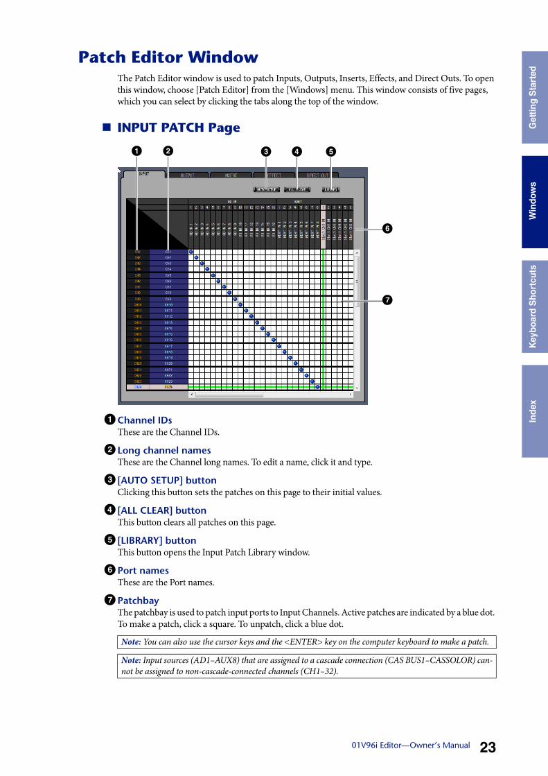
Patch Editor WindowThe Patch Editor window is used to patch Inputs, Outputs, Inserts, Effects, and Direct Outs. To open this window, choose [Patch Editor] from the [Windows] menu. This window consists of five pages, which you can select by clicking the tabs along the top of the window.
INPUT PATCH Page
1 Channel IDsThese are the Channel IDs.
2 Long channel namesThese are the Channel long names. To edit a name, click it and type.
3 [AUTO SETUP] buttonClicking this button sets the patches on this page to their initial values.
4 [ALL CLEAR] buttonThis button clears all patches on this page.
5 [LIBRARY] buttonThis button opens the Input Patch Library window.
6 Port namesThese are the Port names.
7 PatchbayThe patchbay is used to patch input ports to Input Channels. Active patches are indicated by a blue dot. To make a patch, click a square. To unpatch, click a blue dot.
Note: You can also use the cursor keys and the <ENTER> key on the computer keyboard to make a patch.
Note: Input sources (AD1–AUX8) that are assigned to a cascade connection (CAS BUS1–CASSOLOR) can-not be assigned to non-cascade-connected channels (CH1–32).
21 3 4 5
7
6
Usi
ng 0
1V96
Edi
tor
Win
dow
sG
ettin
g S
tart
edK
eybo
ard
Sho
rtcu
tsIn
dex
2401V96i Editor—Owner’s Manual
Win
dow
s
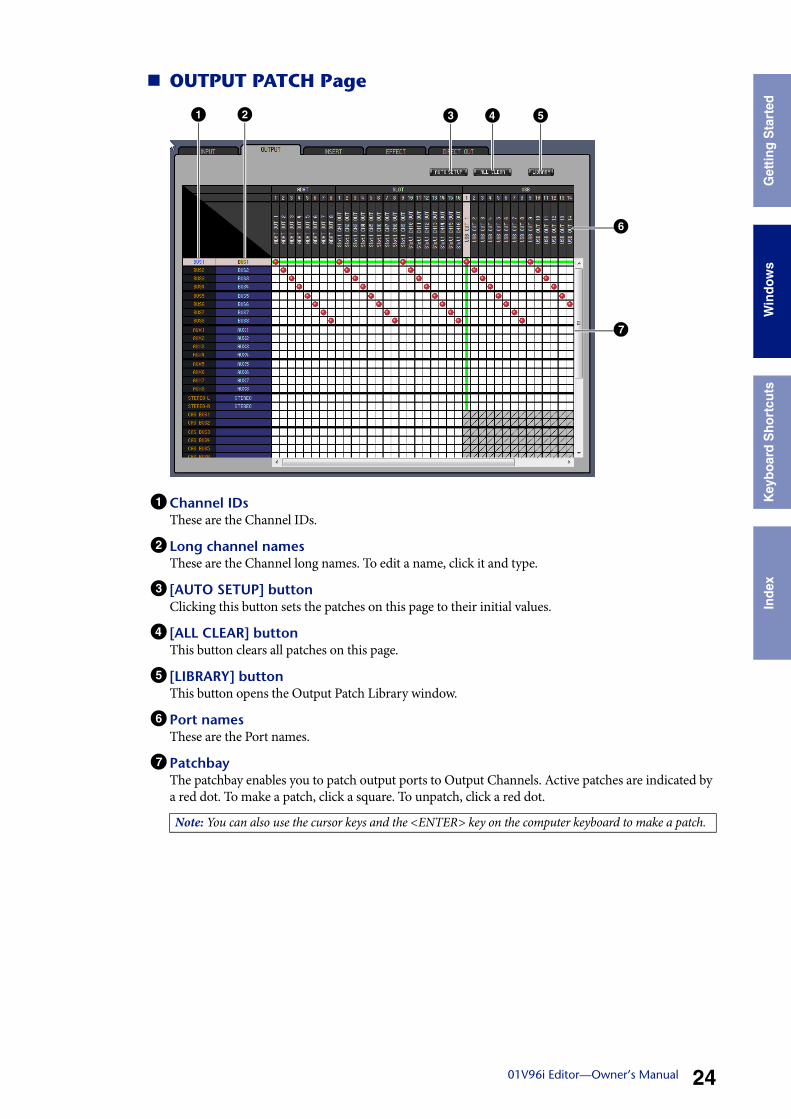
OUTPUT PATCH Page
1 Channel IDsThese are the Channel IDs.
2 Long channel namesThese are the Channel long names. To edit a name, click it and type.
3 [AUTO SETUP] buttonClicking this button sets the patches on this page to their initial values.
4 [ALL CLEAR] buttonThis button clears all patches on this page.
5 [LIBRARY] buttonThis button opens the Output Patch Library window.
6 Port namesThese are the Port names.
7 PatchbayThe patchbay enables you to patch output ports to Output Channels. Active patches are indicated by a red dot. To make a patch, click a square. To unpatch, click a red dot.
Note: You can also use the cursor keys and the <ENTER> key on the computer keyboard to make a patch.
21 3 4 5
7
6
Usi
ng 0
1V96
Edi
tor
Win
dow
sG
ettin
g S
tart
edK
eybo
ard
Sho
rtcu
tsIn
dex
2501V96i Editor—Owner’s Manual
Win
dow
s
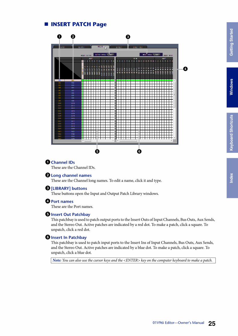
INSERT PATCH Page
1 Channel IDsThese are the Channel IDs.
2 Long channel namesThese are the Channel long names. To edit a name, click it and type.
3 [LIBRARY] buttonsThese buttons open the Input and Output Patch Library windows.
4 Port namesThese are the Port names.
5 Insert Out PatchbayThis patchbay is used to patch output ports to the Insert Outs of Input Channels, Bus Outs, Aux Sends, and the Stereo Out. Active patches are indicated by a red dot. To make a patch, click a square. To unpatch, click a red dot.
6 Insert In PatchbayThis patchbay is used to patch input ports to the Insert Ins of Input Channels, Bus Outs, Aux Sends, and the Stereo Out. Active patches are indicated by a blue dot. To make a patch, click a square. To unpatch, click a blue dot.
Note: You can also use the cursor keys and the <ENTER> key on the computer keyboard to make a patch.
2 3
5 6
4
1
Usi
ng 0
1V96
Edi
tor
Win
dow
sG
ettin
g S
tart
edK
eybo
ard
Sho
rtcu
tsIn
dex
2601V96i Editor—Owner’s Manual
Win
dow
s
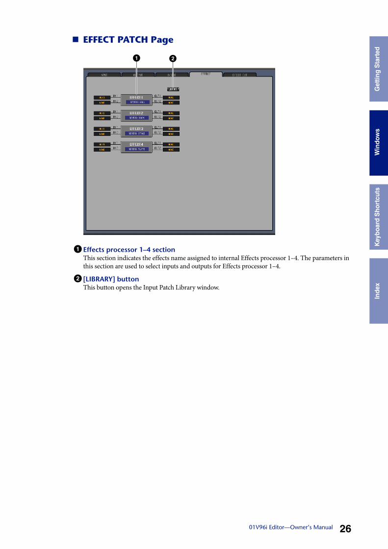
EFFECT PATCH Page
1 Effects processor 1–4 sectionThis section indicates the effects name assigned to internal Effects processor 1–4. The parameters in this section are used to select inputs and outputs for Effects processor 1–4.
2 [LIBRARY] buttonThis button opens the Input Patch Library window.
1 2
Usi
ng 0
1V96
Edi
tor
Win
dow
sG
ettin
g S
tart
edK
eybo
ard
Sho
rtcu
tsIn
dex
2701V96i Editor—Owner’s Manual
Win
dow
s
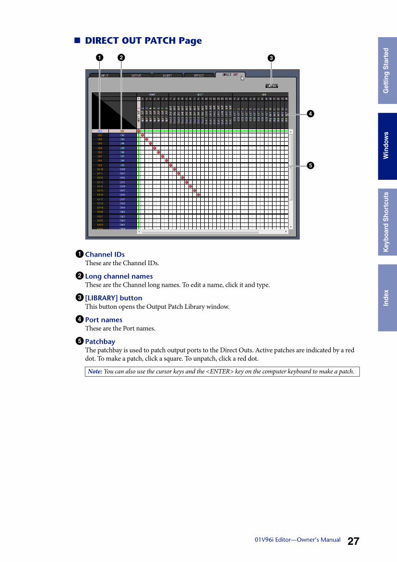
DIRECT OUT PATCH Page
1 Channel IDsThese are the Channel IDs.
2 Long channel namesThese are the Channel long names. To edit a name, click it and type.
3 [LIBRARY] buttonThis button opens the Output Patch Library window.
4 Port namesThese are the Port names.
5 PatchbayThe patchbay is used to patch output ports to the Direct Outs. Active patches are indicated by a red dot. To make a patch, click a square. To unpatch, click a red dot.
Note: You can also use the cursor keys and the <ENTER> key on the computer keyboard to make a patch.
21 3
4
5
Usi
ng 0
1V96
Edi
tor
Win
dow
sG
ettin
g S
tart
edK
eybo
ard
Sho
rtcu
tsIn
dex
2801V96i Editor—Owner’s Manual
Win
dow
s
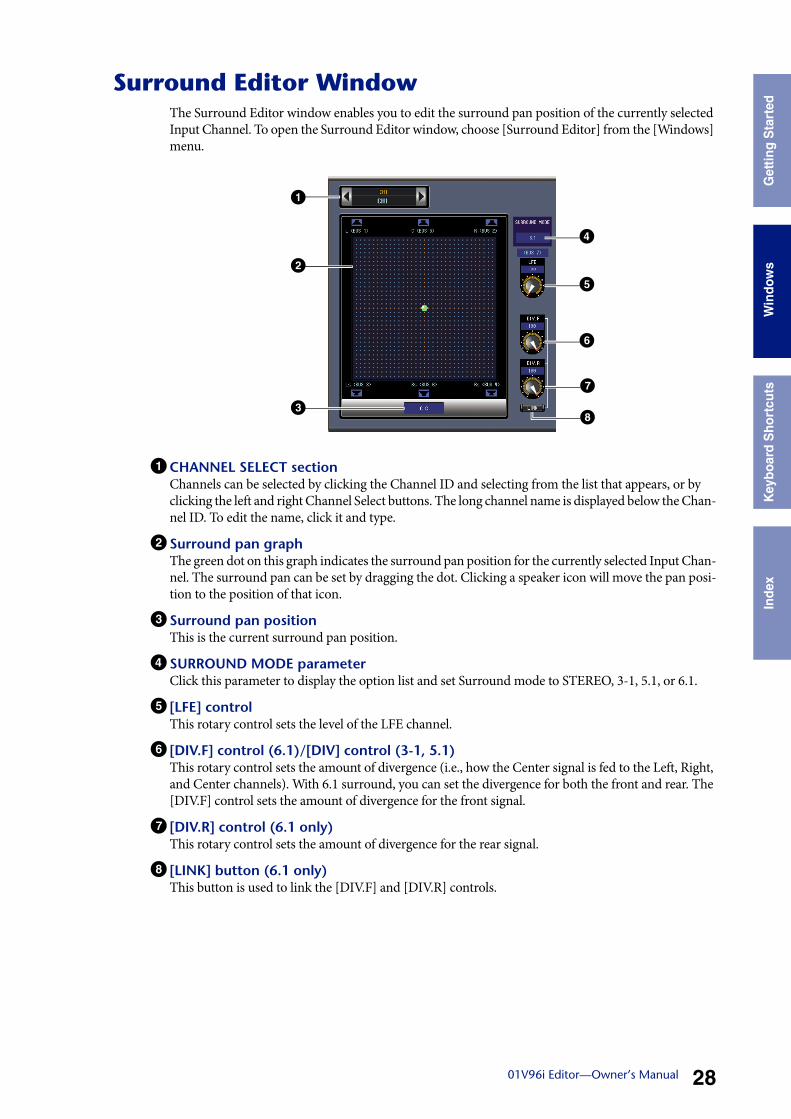
Surround Editor WindowThe Surround Editor window enables you to edit the surround pan position of the currently selected Input Channel. To open the Surround Editor window, choose [Surround Editor] from the [Windows] menu.
1 CHANNEL SELECT sectionChannels can be selected by clicking the Channel ID and selecting from the list that appears, or by clicking the left and right Channel Select buttons. The long channel name is displayed below the Chan-nel ID. To edit the name, click it and type.
2 Surround pan graphThe green dot on this graph indicates the surround pan position for the currently selected Input Chan-nel. The surround pan can be set by dragging the dot. Clicking a speaker icon will move the pan posi-tion to the position of that icon.
3 Surround pan positionThis is the current surround pan position.
4 SURROUND MODE parameterClick this parameter to display the option list and set Surround mode to STEREO, 3-1, 5.1, or 6.1.
5 [LFE] controlThis rotary control sets the level of the LFE channel.
6 [DIV.F] control (6.1)/[DIV] control (3-1, 5.1)This rotary control sets the amount of divergence (i.e., how the Center signal is fed to the Left, Right, and Center channels). With 6.1 surround, you can set the divergence for both the front and rear. The [DIV.F] control sets the amount of divergence for the front signal.
7 [DIV.R] control (6.1 only)This rotary control sets the amount of divergence for the rear signal.
8 [LINK] button (6.1 only)This button is used to link the [DIV.F] and [DIV.R] controls.
1
4
2
3
5
6
7
8
Usi
ng 0
1V96
Edi
tor
Win
dow
sG
ettin
g S
tart
edK
eybo
ard
Sho
rtcu
tsIn
dex
2901V96i Editor—Owner’s Manual
Win
dow
s
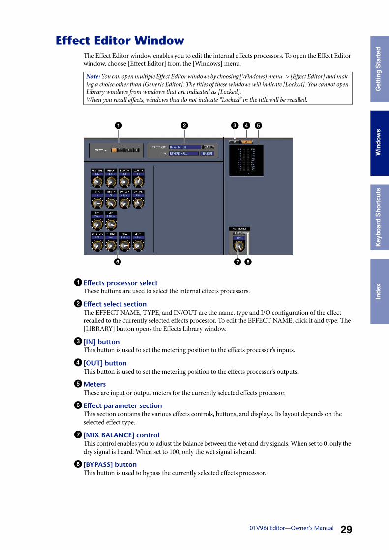
Effect Editor WindowThe Effect Editor window enables you to edit the internal effects processors. To open the Effect Editor window, choose [Effect Editor] from the [Windows] menu.
1 Effects processor selectThese buttons are used to select the internal effects processors.
2 Effect select sectionThe EFFECT NAME, TYPE, and IN/OUT are the name, type and I/O configuration of the effect recalled to the currently selected effects processor. To edit the EFFECT NAME, click it and type. The [LIBRARY] button opens the Effects Library window.
3 [IN] buttonThis button is used to set the metering position to the effects processor’s inputs.
4 [OUT] buttonThis button is used to set the metering position to the effects processor’s outputs.
5MetersThese are input or output meters for the currently selected effects processor.
6 Effect parameter sectionThis section contains the various effects controls, buttons, and displays. Its layout depends on the selected effect type.
7 [MIX BALANCE] controlThis control enables you to adjust the balance between the wet and dry signals. When set to 0, only the dry signal is heard. When set to 100, only the wet signal is heard.
8 [BYPASS] buttonThis button is used to bypass the currently selected effects processor.
Note: You can open multiple Effect Editor windows by choosing [Windows] menu -> [Effect Editor] and mak-ing a choice other than [Generic Editor]. The titles of these windows will indicate [Locked]. You cannot open Library windows from windows that are indicated as [Locked].When you recall effects, windows that do not indicate “Locked” in the title will be recalled.
1 2 53 4
6 7 8
Usi
ng 0
1V96
Edi
tor
Win
dow
sG
ettin
g S
tart
edK
eybo
ard
Sho
rtcu
tsIn
dex
3001V96i Editor—Owner’s Manual
Win
dow
s
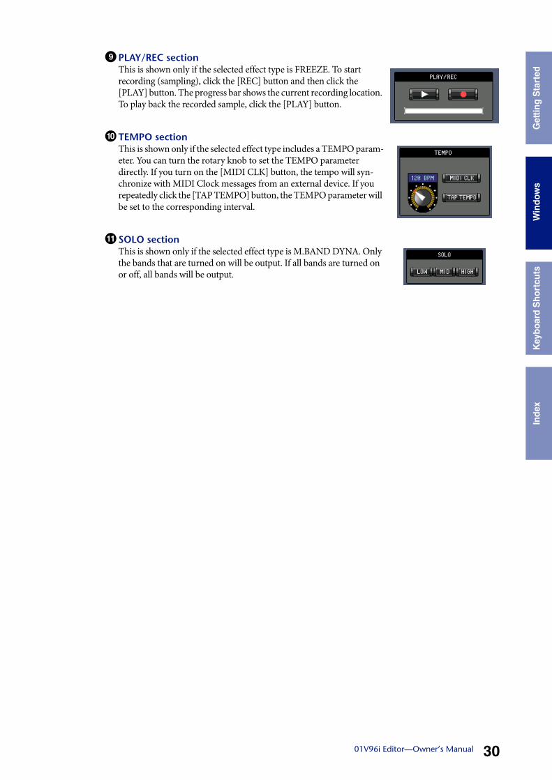
9 PLAY/REC sectionThis is shown only if the selected effect type is FREEZE. To start recording (sampling), click the [REC] button and then click the [PLAY] button. The progress bar shows the current recording location. To play back the recorded sample, click the [PLAY] button.
) TEMPO sectionThis is shown only if the selected effect type includes a TEMPO param-eter. You can turn the rotary knob to set the TEMPO parameter directly. If you turn on the [MIDI CLK] button, the tempo will syn-chronize with MIDI Clock messages from an external device. If you repeatedly click the [TAP TEMPO] button, the TEMPO parameter will be set to the corresponding interval.
! SOLO sectionThis is shown only if the selected effect type is M.BAND DYNA. Only the bands that are turned on will be output. If all bands are turned on or off, all bands will be output.
Usi
ng 0
1V96
Edi
tor
Win
dow
sG
ettin
g S
tart
edK
eybo
ard
Sho
rtcu
tsIn
dex
3101V96i Editor—Owner’s Manual
Win
dow
s
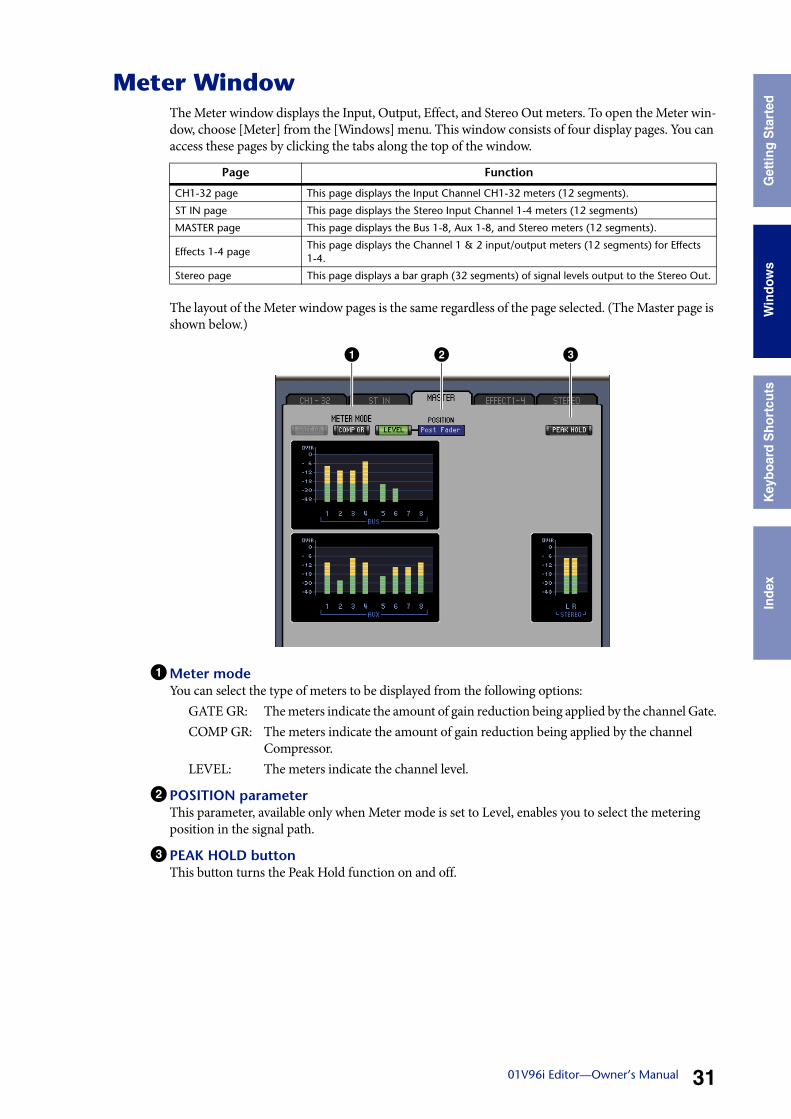
Meter WindowThe Meter window displays the Input, Output, Effect, and Stereo Out meters. To open the Meter win-dow, choose [Meter] from the [Windows] menu. This window consists of four display pages. You can access these pages by clicking the tabs along the top of the window.
The layout of the Meter window pages is the same regardless of the page selected. (The Master page is shown below.)
1Meter modeYou can select the type of meters to be displayed from the following options:
GATE GR: The meters indicate the amount of gain reduction being applied by the channel Gate.COMP GR: The meters indicate the amount of gain reduction being applied by the channel
Compressor.LEVEL: The meters indicate the channel level.
2 POSITION parameterThis parameter, available only when Meter mode is set to Level, enables you to select the metering position in the signal path.
3 PEAK HOLD buttonThis button turns the Peak Hold function on and off.
Page Function
CH1-32 page This page displays the Input Channel CH1-32 meters (12 segments).
ST IN page This page displays the Stereo Input Channel 1-4 meters (12 segments)
MASTER page This page displays the Bus 1-8, Aux 1-8, and Stereo meters (12 segments).
Effects 1-4 pageThis page displays the Channel 1 & 2 input/output meters (12 segments) for Effects 1-4.
Stereo page This page displays a bar graph (32 segments) of signal levels output to the Stereo Out.
1 2 3
Usi
ng 0
1V96
Edi
tor
Win
dow
sG
ettin
g S
tart
edK
eybo
ard
Sho
rtcu
tsIn
dex
3201V96i Editor—Owner’s Manual
Win
dow
s
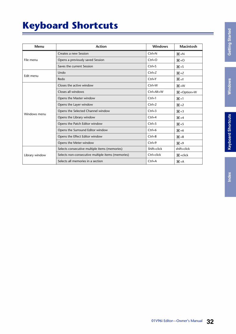
Keyboard Shortcuts
Menu Action Windows Macintosh
File menu
Creates a new Session Ctrl+N +N
Opens a previously saved Session Ctrl+O +O
Saves the current Session Ctrl+S +S
Edit menuUndo Ctrl+Z +Z
Redo Ctrl+Y +Y
Windows menu
Closes the active window Ctrl+W +W
Closes all windows Ctrl+Alt+W +Option+W
Opens the Master window Ctrl+1 +1
Opens the Layer window Ctrl+2 +2
Opens the Selected Channel window Ctrl+3 +3
Opens the Library window Ctrl+4 +4
Opens the Patch Editor window Ctrl+5 +5
Opens the Surround Editor window Ctrl+6 +6
Opens the Effect Editor window Ctrl+8 +8
Opens the Meter window Ctrl+9 +9
Library window
Selects consecutive multiple items (memories) Shift+click shift+click
Selects non-consecutive multiple items (memories) Ctrl+click +click
Selects all memories in a section Ctrl+A +A
Usi
ng 0
1V96
i Edi
tor
Win
dow
sG
ettin
g S
tart
edK
eybo
ard
Sho
rtcu
tsIn
dex
3301V96i Editor—Owner’s Manual
Win
dow
s
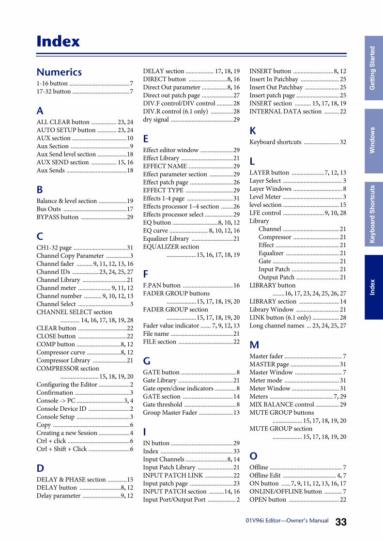
Index
Numerics1-16 button .........................................717-32 button .......................................7
AALL CLEAR button ................. 23, 24AUTO SETUP button ............. 23, 24AUX section .....................................10Aux Section ........................................9Aux Send level section ....................18AUX SEND section ................. 15, 16Aux Sends .........................................18
BBalance & level section ...................19Bus Outs ...........................................17BYPASS button ...............................29
CCH1-32 page ....................................31Channel Copy Parameter ................3Channel fader ...........9, 11, 12, 13, 16Channel IDs ..................23, 24, 25, 27Channel Library ..............................21Channel meter ...................... 9, 11, 12Channel number ............ 9, 10, 12, 13Channel Select ...................................3CHANNEL SELECT section
............. 14, 16, 17, 18, 19, 28CLEAR button .................................22CLOSE button .................................22COMP button ..............................8, 12Compressor curve .......................8, 12Compressor Library .......................21COMPRESSOR section
..........................15, 18, 19, 20Configuring the Editor .....................2Confirmation .....................................3Console -> PC ................................3, 4Console Device ID ............................2Console Setup ....................................3Copy ....................................................6Creating a new Session .....................4Ctrl + click ..........................................6Ctrl + Shift + Click ............................6
DDELAY & PHASE section .............15DELAY button ............................8, 12Delay parameter ..........................9, 12
DELAY section ................... 17, 18, 19DIRECT button ..........................8, 16Direct Out parameter .................8, 16Direct out patch page .....................27DIV.F control/DIV control ...........28DIV.R control (6.1 only) ...............28dry signal ..........................................29
EEffect editor window ......................29Effect Library ...................................21EFFECT NAME ..............................29Effect parameter section ................29Effect patch page .............................26EFFECT TYPE ................................29Effects 1-4 page ...............................31Effects processor 1–4 section ........26Effects processor select ...................29EQ button ...............................8, 10, 12EQ curve .......................... 8, 10, 12, 16Equalizer Library ............................21EQUALIZER section
....................15, 16, 17, 18, 19
FF.PAN button ..................................16FADER GROUP buttons
....................15, 17, 18, 19, 20FADER GROUP section
....................15, 17, 18, 19, 20Fader value indicator ....... 7, 9, 12, 13File name ..........................................21FILE section .....................................22
GGATE button .....................................8Gate Library .....................................21Gate open/close indicators ..............8GATE section ..................................14Gate threshold ...................................8Group Master Fader .......................13
IIN button ..........................................29Index .................................................33Input Channels ............................8, 14Input Patch Library ........................21INPUT PATCH LINK ...................22Input patch page .............................23INPUT PATCH section ..........14, 16Input Port/Output Port ...................2
INSERT button ........................... 8, 12Insert In Patchbay .......................... 25Insert Out Patchbay ....................... 25Insert patch page ............................. 25INSERT section ........... 15, 17, 18, 19INTERNAL DATA section .......... 22
KKeyboard shortcuts ........................ 32
LLAYER button ......................7, 12, 13Layer Select ........................................ 3Layer Windows ................................. 8Level Meter ........................................ 3level section ...................................... 15LFE control ............................9, 10, 28Library
Channel ...................................... 21Compressor ............................... 21Effect ........................................... 21Equalizer .................................... 21Gate ............................................. 21Input Patch ................................ 21Output Patch ............................. 21
LIBRARY button........16, 17, 23, 24, 25, 26, 27
LIBRARY section ........................... 14Library Window ............................. 21LINK button (6.1 only) .................. 28Long channel names ... 23, 24, 25, 27
MMaster fader ....................................... 7MASTER page ................................. 31Master Window ................................ 7Meter mode ..................................... 31Meter Window ................................ 31Meters ...........................................7, 29MIX BALANCE control ................ 29MUTE GROUP buttons
.................... 15, 17, 18, 19, 20MUTE GROUP section
.................... 15, 17, 18, 19, 20
OOffline ................................................. 7Offline Edit .................................... 4, 7ON button ......7, 9, 11, 12, 13, 16, 17ONLINE/OFFLINE button ............ 7OPEN button .................................. 22
Usi
ng 0
1V96
i Edi
tor
Win
dow
sG
ettin
g S
tart
edK
eybo
ard
Sho
rtcu
tsIn
dex
3401V96i Editor—Owner’s Manual
Win
dow
s
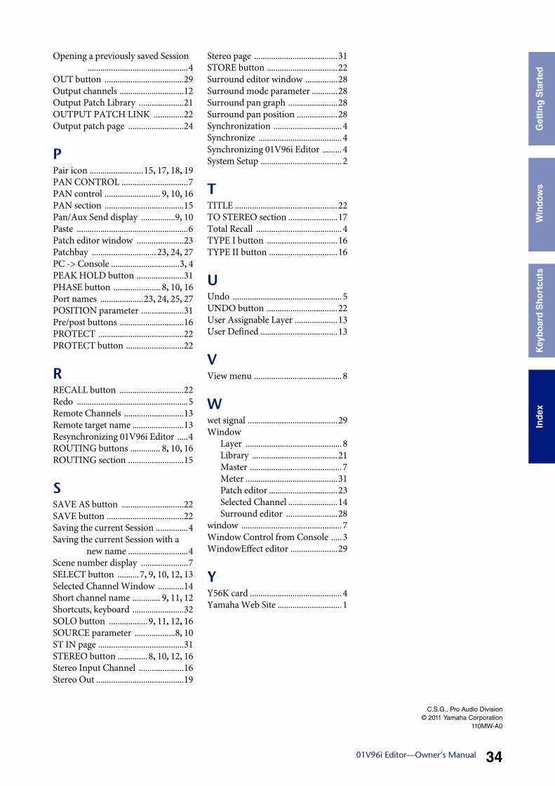
Opening a previously saved Session...............................................4
OUT button .....................................29Output channels ..............................12Output Patch Library .....................21OUTPUT PATCH LINK ..............22Output patch page ..........................24
PPair icon .........................15, 17, 18, 19PAN CONTROL ...............................7PAN control .......................... 9, 10, 16PAN section .....................................15Pan/Aux Send display ................9, 10Paste ....................................................6Patch editor window ......................23Patchbay .............................. 23, 24, 27PC -> Console ................................3, 4PEAK HOLD button ......................31PHASE button ...................... 8, 10, 16Port names ....................23, 24, 25, 27POSITION parameter ....................31Pre/post buttons ..............................16PROTECT ........................................22PROTECT button ...........................22
RRECALL button ..............................22Redo ....................................................5Remote Channels ............................13Remote target name ........................13Resynchronizing 01V96i Editor .....4ROUTING buttons .............. 8, 10, 16ROUTING section ..........................15
SSAVE AS button .............................22SAVE button ....................................22Saving the current Session ...............4Saving the current Session with a
new name ............................4Scene number display ......................7SELECT button ..........7, 9, 10, 12, 13Selected Channel Window ............14Short channel name ............. 9, 11, 12Shortcuts, keyboard ........................32SOLO button ..................9, 11, 12, 16SOURCE parameter ...................8, 10ST IN page ........................................31STEREO button .............. 8, 10, 12, 16Stereo Input Channel .....................16Stereo Out .........................................19
Stereo page .......................................31STORE button .................................22Surround editor window ...............28Surround mode parameter ............28Surround pan graph .......................28Surround pan position ...................28Synchronization ................................4Synchronize .......................................4Synchronizing 01V96i Editor .........4System Setup ......................................2
TTITLE ................................................22TO STEREO section .......................17Total Recall ........................................4TYPE I button .................................16TYPE II button ................................16
UUndo ...................................................5UNDO button .................................22User Assignable Layer ....................13User Defined ....................................13
VView menu .........................................8
Wwet signal ..........................................29Window
Layer .............................................8Library ........................................21Master ...........................................7Meter ...........................................31Patch editor ................................23Selected Channel .......................14Surround editor ........................28
window ...............................................7Window Control from Console .....3WindowEffect editor ......................29
YY56K card ...........................................4Yamaha Web Site ..............................1
C.S.G., Pro Audio Division© 2011 Yamaha Corporation
110MW-A0
Top Related