


Languages
Pages
Legal


AD-A73 123 FOREIGN TECHNOLOGY DIV WRIGHT-PATTERSON AFS OH FIG 1/3THE MIG-25, A VERY HIGH SPEED INTERCEPTOR AND RECONNAISSANCE AlI-ETC4U)JUL 81 Z MARINKOVAC
UNCLASSIFIED 6 TD-If(RS)T-0541-81
*EOR

FOR),EIGN TECHNOLOGY DIVISION
7TfIC~16
THE MC -25, A ',RL .G -rE~ - 1C.T~
AND RECOM1;:JAT-3ANC7 Al RCR7
by
I Zoran NarinIkovic
AipcvdfrpbIcrlae
ditiuin n.mtd

FTD-ID (;i:.2T-C,5*n412?
EDITED VF2Ak':5'LAT1ON
/I FTD-ID(RS)T-05141-81 17 Jul* 1.981
MICROFICHE NR: FTD-81-C-000628
THMIG-25, A VERY HIGH SPEED INTERCEPTORAND RECO!,'NAIsSSANCE AIRCRAFT_
Bya;-- Zoran; Narinkovic
Eneio., pages.:. G
Country of origin: KPoland)Translated by: S " -ITRA-14--
F33657-T8-D-0619Requester: FTD/SDNSApproved for public release; distributionunlimited.
THIS TRANSLATION IS A RENDITION OF THE ORIGI.NAL FOREIGN TEXT WITHOUT ANY ANALYTICAL OREDITORIAL COMMENT. STATEMENTS OR THEORES PREPARED BY:ADVOCATED OR IMPLIEDOARE THOSE OF THE SOURCEANODO NOT NECESSARILY REFLECT THE POSITION TRANSLATION tIVISIONOR OPINION OF THE FOREIGN TECHNOLOGY DI- FOREIGN TECHNOLOGY DIVISIONVISION. WP.AFS, OHIO.
FTD-D(RST-051-81Date7 Ju 98

THE A23-5 AVElY IIH SIPEED 1I:TiLPTURAND~ RLCO.IhAIS A:;C. AIRCRhAlT
Zoran ".1arinkovic

Because of the lack of data and the limited information from Soviet
sources, the aircraft discussed here is only called the FOXBAT. The NATO mili-
tary forces have given it this name just because of its appearance.
Rapid work on the production of a new Soviet military aircraft was already
begun in the 1950's, immediately after the F-4 Phantom II entered military
service.
At this time (1960) the Soviet RV [expansion unknown] possessed several
different versions of the MiG-21, which were comparable in every respect to
those of their Western enemies. Its designers, Mikojana and Gurjevica, tried
to design a better airplane in line with new tactical and technological re-
quiremnents. At this time the MiG-21 possessed a speed of 2 Mach, but the
transition from 2 Mach to 3 Mach was a very long and complex path. It was
necessary to solve a number of problems in its structure, thrust assembly and
other systems. The aircraft design was begun in 1960, and the first prototype
was flown in 1962.
It is thought that the lack of time forced the Soviet designers to
have recourse in tested structural technology, requiring the use of steel in
the production of all structural elements exposed to high loads.
As a result of this the structure is naturally heavy, but it was built
relatively fast, and only areas exposed to high thermal overload, such as the
leading edges of the wings and the tail surfaces, were made of titanium.
The small proportion of titanium in the structure caused the USSR to
have difficulties In the 1960's in using the structural elements with tita-
nium, not at all connected with the significantly higher costs. The Americans
lik~ewise had problems with the use of titanium in the B-70.

in... . . . ..-
• . ...'-I .: ,,- ... "
I t
I ,. p
: .. .. t. . . . . -
-,--.
S 4
According to data in the Western aircraft press, MiG-25 was put into
operational use in the 1966-1970 period. The MG-25 is one of the first modern
Soviet aircraft equipped for all kinds of operational missions, day and night
and under all weather conditions.
Structure
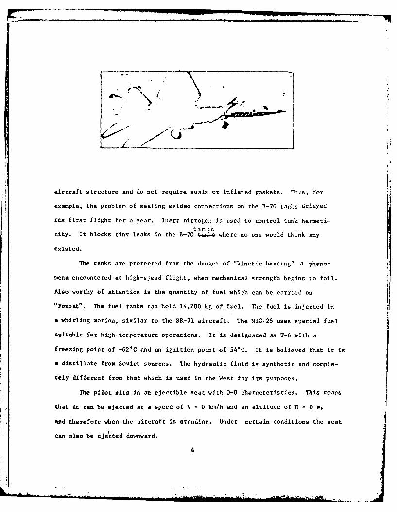
The MiG-25 was built without any special aerodynamic compromises for
direct supersonic flight at high altitudes. It flies "nose up" at extreme
speeds and altitudes. 9
The MIG-25 aircraft is a two-engine, high-wing airplane with slim delta
wings swept somewhat backwards, horizontal arrowlike tail surfaces, and separate
vertical tail surfaces.

-I0-',% Il
The fuselage has an oval cross-section with large lateral, rectangular
air ducts (3.2 x 1.2 m in size) ,and cut obliquely in the front.
Both jets of the aircraft are built parallel into the rear part of the
fuselage. An adjustable fin is built into the belly to prevent rotation around
the transverse axis.
Air brakes are built into the upper part of the fuselage. A hook has
been built into the lower part of the fuselage to reduce rolling on landing.
Braking parachutes 7 m in diameter are used for short landings. A
launching rocket, built into the rear of the fuselage, is used for short
take-off s. The permanent gangway is stored in the fuselage because there is
no room in the slim wings.
On the MIG-25 the fuel tanks are located on the fuselage and wings.
Sealing the fuel tanks presents a real problem at high speeds, but it has been
solved very successfully on the MiC-25. The tanks are welded directly onto the
3
aircraft structure and do not require seals or inflated gaskets. Thus, for
example, the problem of sealing welded connections on the B-70 tanks delayed
its first flight for a year. Inert nitrogen is used to control tank hermeti-
tankscity. It blocks tiny leaks in the B-70 U where no one would think any
existed.
The tanks are protected from the danger of "kinetic heating" a pheno-
mena encountered at high-speed flight, when mechanical strength begins to fail.
Also worthy of attention is the quantity of fuel which can be carried on
"Foxbat". The fuel tanks can hold 14,200 kg of fuel. The fuel is injected in
a whirling motion, similar to the SR-71 aircraft. The MiG-25 uses special fuel
suitable for high-temperature operations. It is designated as T-6 with a
freezing point of -62*C and an ignition point of 54*C. It is believed that it is
a distillate from Soviet sources. The hydraulic fluid is synthetic and comple-
tely different from that which is used in the West for its purposes.
The pilot sits in an ejectible seat with 0-0 characteristics. This means
that it can be ejected at a speed of V - 0 km/h and an altitude of II - 0 m,
and therefore when the aircraft is standing. Under certain conditions the seat
can also be ejected downward.
4

- -.. ...
The propulsion system is the biggest surprise. According to one report
the Tumanski RD-31 jet engine was developed as a thrust engine for supersonic
unmanned aircraft. The RD-31 engine is about as complex as the Rolls-Royce
Viper motor, with one shaft, a five-stepped compressor for which the West has
no equivalent, a one-step turbine and a lift ratio of 7:1. There is no variable
geometry, and the stators are welded to the engine housing. The turbine is not
cooled. For the most part the motor elements are made of steel with titanium
in the compressor and jet sections.
The temperature at the entrance of the turbine is 1120 kelvins.
Electronic Equipment
Special attention was devoted to the electronic equipment. The MiG-25
has electronic devices which are not inferior to American ones.
It is equipped with radar with a corresponding computer for aiming guided
air-air rockets. Infrared radiation tracking equipment makes it possible to
attack all aircraft which have jet or rocket enrines.
5
6 - 1 AW".;Lk~.!-AI
The computer to control flight uses vacuum tubes, and is connected to
ground control. The MiG-25, Just like other Soviet interceptors, is puided
by ground-based operators for the greater part of its mission. Pilot responsi-
bility is limited to take-off, gas regulation and landing. The computer can
return the aircraft to any of four designated bases, and can also process input
data from radar and other sensors.
The autopilot works in conjunction with the computer to guide the aircraft
at the optimal flight regime. In addition to this, it is equipped with two
radars to detect obstacles and to track the terrain, also operating in conjunc-
tion with the autopilot, making it possible to operate successfully at low
altitudes (fence-hopping).
This equipment functions faster than a pilot, because fence-hopping
at supersonic speeds exceeds the limits of human ability.
The length of all cables and wires in the MiG-25 electronic system is
approximately 50 km, and the number of its electronic tubes and transistors
exceeds 20,000.
MiG-25 Foxbat-A
The MiG-25 Foxbat-A is an interceptor with two highly-placed delta wings.
Sonm 37% of the free surface of the wings is protected.
Fox-Fire X-Band aircraft search radar with a 0.85 m spherical antenna
and a maximal impulse output power of 600 kW is the most powerful fire-control
radar in the world. The radar is installed in the nose space of the fuselage,
along with its large electronic system. "4'" radar uses electron tube tech-
nology and is considerably heavier than Western counterparts.
Its great power makes it possible to detect and track targets at great
distances, eveto in the presence of relatively powerful electronic interference.
6
.1. -
Judging froia its main parameters (thrust and weight ratio, sp(ecific
wing load, electronic equipment and armament), Foxbat-A is built for very fast
and high reconnaissance missions, in addition to its primary Interceptor role.
The MiG-25 can be used as an armed aircraft carrying air-ground rockets with a
range of 100-200 kin. In this role the MiG-25 can be used predominantly for
attacking radar stations and ships in coastal zones.
MiG-25 R Foxbat-B
Since the B-70 bomber was the primary MiC target, the USSR began the
serious production of a fighter, although in a more limited scope than the
standard fighter intended for territorial defense, such as the SU-15 Flagon.
However, secondary capabilities of the MiG-25 R, as a military reconnaissance
aircraft, were established very quickly. Differently from Foxbat-A, Foxbat-BJAYBIRD
has only J.ap=d.-radar, probably used for non-military purposes in low flight
operations. It is totally incapable of bearing armament, so that it can be
anticipated that the strong points under the wings will be used in the future
for external fuel tanks. The military reconnaissance equipment of Foxbat-B
consists of five cameras mounted in the nose section. Two of them are turned
to the right and two to the left at angles of 150 with respect to the vertical.
From an altitude of 24 km it can take useful photographs from cameras angled
at 45* in a corridor 70 km wide. The five cameras produce vertical photographs
and probably have telescopic lenses in order to be able to provide sharp images
of individual targets which must be attacked. The Foxbat-B cameras also carry
additional IC (infrared: IR] equipment for rectilinear observation with
feedback sensors which can clearly see from both sides of the fuselage nose
section. Nothing is known of the capacity of this reconnaissance equipment, but
it may be presumed that optical and IR photography cover the same area, up to
70 km in width.
7
. .-
NiC-25 U Foxbat-C
As in the case of other Soviet heavy fiphters and bombers, the training
version of the iG-25 has also been developed with the addition of a second
pilot cabin. The result of this is very restricted electronic equipment, and
not even the (I -- i aar is installe6, clearly indicatinp that the Foxbat-C
would be used exclusively for training purposes, at lest currently.
However, it is also possible that a 2-seater version will later be developed
with a second cabin of very suitable aerodynamic features. With the proper
equipment and armament, which can consist of guided and unguided rockets or
air-ground rockets, this version of the MiC-25 could be used as a bomber
to attack strategic targets.
MiG-25 RE Foxbat-D
This version of tle MiG-25 differs from the Foxbat-B in that a radar
is installed for lateral observation of considerable areas, instead of the
camera and IR equipment for rectilinear observation. Little is known of the
capability of this radar equipment but conclusions about it can be drawn in
consideration of the operating altitude and the size of the available radar
antennae which indicate the possibility of reconnaissance to a depth of 100 km
from both sides of the aircraft (across the flight path).
MiG-25 It Foxbat-E (?)
According to what has been written in the Western press an interceptor
version has also been developed, the Foxbat-E. In this aircraft the structure,
engine, electronic equipment and armament have been considerably improved. The
structure is reinforced to the extent that it is possible to reach a speed of
M-1 immediately above the sea (in contrast to Mach 0.85 in other Mig-25 versions
under the same conditions). The engine has a considerably improved performance
(RD-F or RD-F3) enobling a maximal thrust of 14,000 kp instead of 11,200 kp in
the engines of the older model. In addition Foxbat-E, in consideration of its
8

newly r-odified radar and improved rocket guidjance system, now exhibits its
real ability to attack low-flying- targets. The number of projectiles has been
increased from 4 to 6 with the addition of two lawicliers on the fuselage, so
that interceptor missions can be implemented with a combination of AA-6 ACRID
and AA-7 APEX roct'ets.
The AA-6 ACRID and AA-7 APEX air-air rockets are missJles wbich are pro-
duced in two versions, one with semi-active radar control and the second with
passive infrared control.
Both rockets are used in such a way that two rockets are successively
launched at a target in an interval of less than 1 second, the first with IR
control. In order to achieve greater lateral acceleration, the AA-7 rocket has
a cross-shaped command surface at the front of the rocket and stabilizers at
the rear. This version is intended to intercept high speed aircraft with high-
altitude maneuvering capabilities.
The MiG-25 is probably equipped with cannons which are either the 23 mm
double-tube GS-23 or the MiG-27 six-tube piece.
The operating capacity of the MiG-25 M is now greater because of the
structural reinforcement, the better thrust/weight ratio, the improved elec-
tronic equipment and the armament. The AA-7 APEX missiles will probably be
the exclusive armament used in future missions.
Conclusion
By using tested technology in the MiG-25, the designers succeeded in
developing a high-performance military aircraft in a relatively short tive,
capable of adequately fulfilling its role in the existing weapons system.
It is a fact that in some structural solutions the technology has not developed
as in the West. However, the appearance of the MiG-25 M demonstrates that
Foxbat is opening a phase of modernization. In the immediace future we can
expect a new version of the RiG which will exceed the current family of mili-
tary aircraft. 9

MiG-25 Tactical and Technical Data
Total length, m 22.30
Wing spread, m 14.00
Wing area, m2 59
Specific wing load, kg/ 2 578
Weight cf equipped aircraft, kg 20,000
Fuel in internal tanks, kg 14,000
Thrust from one engine, kp 7,600 t
Thrust from one engine at top power, kp 11,200
Weight on one engine, kg 2,100
Air flow in engine, kg/sec 170
Maximal speed at sea level, Mach 0.85
Maximum high-altitude speed, Mach 2.80
Climbing speed at sea level, m/s 208
Climbing speed at high altitude, m/s 260
Time to climb to 12 kin, in min 2.1
Time to climb to 24 km, in min 8.6
Take-off distance, m 1,380
Take-off distance to altitude of 15 m, in m 2,800
Landing speed, km/h 270
Rolling distance on landing, m 2,180
Radius of action, km 2,700
Practical flight ceiling, m 24,000
10
b.A - . . - " . . .. , . : .

I; I i I I (1I I I
AdV', 9A" IlkA2 10 A'%:U 3 .i,4 ..IA,-(' - 2C9
C'A(, I I A
C c, I ' I I C ' ! ; A I 1 J~ i A i -M'C 1.11 iU-AY1
C 5 i l lA t -i -6q - k
C5 .P) f'~N
Qtj 19 MIA 141GTU4U
E05J I3 LI A/INET 1S4j i~/INA
E4 10A:/INU-129 Z /1NDv~uu5 WU)/ I SIVDVIi,00 QIA,/W1VAL/SD)
A!'*
N1iIS
NA1A/NS'1'-44N!;W/ 2 1 J/TI1)L
FTD-ID(RS)T-054 1-81

Top Related