


Languages
Pages
Legal

© 2017 JETIR September 2017, Volume 4, Issue 9 www.jetir.org (ISSN-2349-5162)
JETIR1709089 Journal of Emerging Technologies and Innovative Research (JETIR) www.jetir.org 608
THREE PHASE GENERALIZED 63 LEVEL
MULTILEVEL INVERTER FED INDUCTION
MOTOR DRIVE WITH INTELLIGENT
CONTROLLERS
1 Mr.Bolla Madhusudana Reddy 2 N.Shanmuka Sundaram 3K.Vijay kumar 1Assistant Professor, 2Professor, 3Professor.,
1Dept.of EEE, 1Annamacharya Institute of Technology, A.P, India.
Abstract : Multilevel inverters play a pivotal role for smooth functioning of AC drives, pumps, UPS, railway locomotives, grid
connected photovoltaic systems and are grabbed attention by many researchers mainly because of their minimal harmonic distortion
and production of good quality output power compared to conventional two level inverters. Against this back drop this paper presents
63 level optimal structured single phase multilevel inverter by means of fewer switches and Sinusoidal Pulse Width Modulation-
(SPWM) technique used according to the requirements the switches were operated. In the next step three phase optimal cascaded 63
level multilevel inverter with same SPWM controlling technique is implemented. In the consequent step closed loop optimal cascaded
high level multilevel inverter feeding induction motor (IM) drive with Fuzzy Logic Controller (FLC) has been designed. To further
better performance with same drive, replace FLC with Adaptive Neuro Fuzzy Inference System (ANFIS) controller by verifying
voltage, current, distortion and speed- torque under no load and ON load conditions. By following the above mentioned methods the
proposed drive of validity has been proved with MATLAB/SIMULINK.
Index terms: Multilevel inverter, Induction motor, FLC, ANFIS, THD, Speed, Torque.
I. INTRODUCTION
The multilevel inverters (MLIs) are consisting of power semiconductor switches arranged in such a manner
with number of DC voltage sources used for generating alternating wave form with different steps of voltage
levels. When compared to classical two level inverters these MLIs [1-2] have tremendous features such as low
switching losses, low electromagnetic interference, and minimum distortion, reduced dv/dt stress on load and
quality output waveform. If number of levels are improved in output waveform that leads to decrease total
harmonic distortion. Another advantage of MLIs is high voltage requirement is achieved by connecting modules
of MLIs in a series manner. The applications of MLIs are UPS, speed control of AC drives, HVDC system,
reactive power compensators and smart grid with PV system. Generally classical MLIs are categorized into three
types (i) Neutral point or diode clamped MLIs [3] (ii) Flying or fixed capacitor MLIs [4] (iii) Cascaded multilevel
inverters [5]. With above classical MLIs some other topologies are symmetric & asymmetric multilevel inverters
[6-7], hybrid type MLIs with combination of diode clamped and flying capacitor. The performance investigation
for four - Switch three phase Inverter with PI and FLC was implemented [8].A control technique was
implemented with new neural network applicable to induction motor [9].An induction motor had been controlled
by using direct torque control method with sophisticated lookup tables based on neural networks. Common mode
voltage can be minimized using novel space vector PWM with direct torque control feeding induction motor
[10]. Acoustical noise was reduced by using random operated SVPWM for induction motor with direct torque
control technique.
Initially in industry applications three phase inverter with six switches were used which were not suitable for
medium and high voltage or power requirements due to high switching losses, controlling technique complexity
and low quality output. To avoid such problems, classical multilevel inverters were designed and implemented.
Problems in classical MLIs were - more switching devices, DC sources with high standing voltages and
distortion. Most of the industrial requirements three phase induction motors were used due to their simple
construction and ruggedness. Ancient days speed control AC motor done with three phase voltage source inverter
(VSI) but this drive speed torque performance was very poor. In order to improve drive performance, classical
MLIs were replaced in place of VSIs.
Still to improve performance of AC motor drives an optimal structured 63 level MLI is proposed with
minimum required count of switches and DC sources through sinusoidal pulse width modulation control
technique for proper operation switches. The proposed MLI produces very low switching losses, low off state
voltage drops and minimum total harmonic distortion-(THD) due to the cause of almost sinusoidal output wave
form at output with more levels. The proposed MLI control of induction motor drive through FLC is compared
with proposed MLI feeding induction motor drive with ANFIS controller for achieving better speed torque
performance.
© 2017 JETIR September 2017, Volume 4, Issue 9 www.jetir.org (ISSN-2349-5162)
JETIR1709089 Journal of Emerging Technologies and Innovative Research (JETIR) www.jetir.org 609
II. DESIGN OF OPTIMAL CASCADED HIGH LEVEL MULTILEVEL
INVERTER
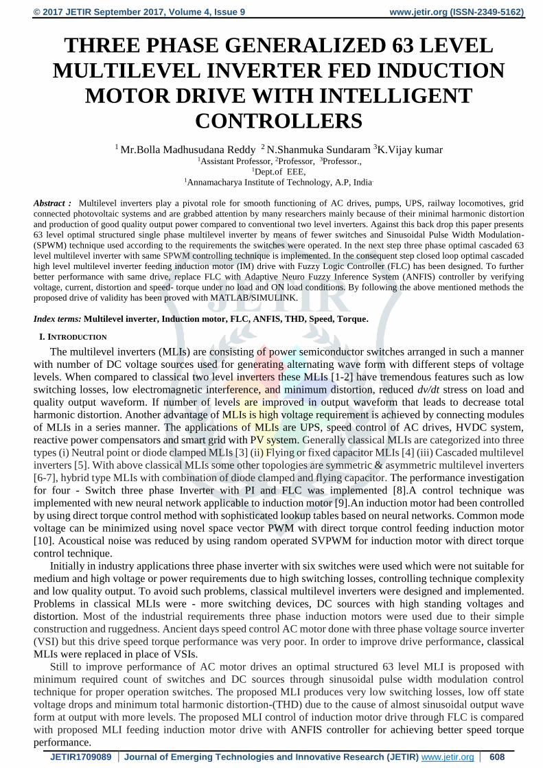
The proposed optimal cascaded 63 level MLI is shown in figure 1 which is designed with series connection of ‘u’ number of
sub units to achieve more steps of voltage levels in output waveform. Each sub unit contains two switches with
one DC source. A number of output levels in voltage wave form decided based on quantity of DC sources applied
in every one sub division of proposed MLI. If all ‘s’ number of DC sources values are same then low levels are
obtained in output but with different values of DC sources with ratio of 1:2:4:8:16 applied to respective sub units,
more number of levels are achieved in output.
12),2(
1,42
swhensu
swhenuNSWITCH
2SWITCHDRIVER NN
342 usN IGBT 4* suN SOURCE
5............... ,2,1, UDCDCDC VVV
6,12 equalsourcesDCIfuN LEVEL
uJwhere
VsV DC
J
JDC
........3,2,1
71 1,
1
,
8,12 1 unequalsourcesDCIfN u
LEVEL
Where JDCV , , SWITCHN
, DRIVERN,
IGBTN, SOURCEN
, LEVELN are the DC voltage of Jth Sub unit, No. Of
switches, No. Of switches’ drivers, No. of IGBTs and total No. of Sources for proposed MLI. The Series
connected sub units of proposed MLI produces only zero and positive levels of output. An H bridge linked with
series combination of sub units to obtain negative levels in addition to positive levels and zero level. The positive
levels of output voltages are obtained during the ON condition of ‘H1’ and ‘H4’ devices in the H-Bridge and
negative levels of output voltages are achieved for ON position of ‘H2’ and ‘H3’ in the H-Bridge
‘
Figure 1.Single phase proposed optimal cascaded 63 level MLI
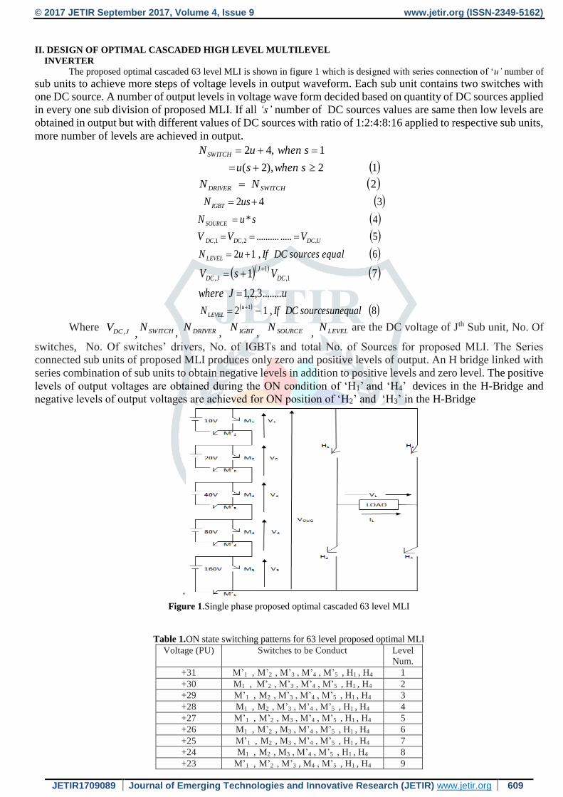
Table 1.ON state switching patterns for 63 level proposed optimal MLI
Voltage (PU) Switches to be Conduct Level
Num.
+31 M’1 , M’2 , M’3 , M’4 , M’5 , H1 , H4 1
+30 M1 , M’2 , M’3 , M’4 , M’5 , H1 , H4 2
+29 M’1 , M2 , M’3 , M’4 , M’5 , H1 , H4 3
+28 M1 , M2 , M’3 , M’4 , M’5 , H1 , H4 4
+27 M’1 , M’2 , M3 , M’4 , M’5 , H1 , H4 5
+26 M1 , M’2 , M3 , M’4 , M’5 , H1 , H4 6
+25 M’1 , M2 , M3 , M’4 , M’5 , H1 , H4 7
+24 M1 , M2 , M3 , M’4 , M’5 , H1 , H4 8
+23 M’1 , M’2 , M’3 , M4 , M’5 , H1 , H4 9
© 2017 JETIR September 2017, Volume 4, Issue 9 www.jetir.org (ISSN-2349-5162)
JETIR1709089 Journal of Emerging Technologies and Innovative Research (JETIR) www.jetir.org 610
+22 M1 , M’2 , M’3 , M4 , M’5 , H1 , H4 10
+21 M’1 , M2 , M’3 , M4 , M’5 , H1 , H4 11
+20 M1 , M2 , M’3 , M4 , M’5 , H1 , H4 12
+19 M’1 , M’2 , M3 , M4 , M’5 , H1 , H4 13
+18 M1 , M’2 , M3 , M4 , M’5 , H1 , H4 14
+17 M’1 , M2 , M3 , M4 , M’5 , H1 , H4 15
+16 M1 , M2 , M3 , M4 , M’5 , H1 , H4 16
+15 M’1 , M’2 , M’3 , M’4 , M5 , H1 , H4 17
+14 M1 , M’2 , M’3 , M’4 , M5 , H1 , H4 18
+13 M’1 , M2 , M’3 , M’4 , M5 , H1 , H4 19
+12 M1 , M2 , M’3 , M’4 , M5 , H1 , H4 20
+11 M’1 , M’2 , M3 , M’4 , M5 , H1 , H4 21
+10 M1 , M’2 , M3 , M’4 , M5 , H1 , H4 22
+9 M’1 , M2 , M3 , M’4 , M5 , H1 , H4 23
+8 M1 , M2 , M3 , M’4 , M5 , H1 , H4 24
+7 M’1 , M’2 , M’3 , M4 , M5 , H1 , H4 25
+6 M1 , M’2 , M’3 , M4 , M5 , H1 , H4 26
+5 M’1 , M2 , M’3 , M4 , M5 , H1 , H4 27
+4 M1 , M2 , M’3 , M4 , M5 , H1 , H4 28
+3 M’1 , M’2 , M3 , M4 , M5 , H1 , H4 29
+2 M1 , M’2 , M3 , M4 , M5 , H1 , H4 30
+1 M’1 , M2 , M3 , M4 , M5 , H1 , H4 31
0 M1 , M2 , M3 , M4 , M5 32
-31 M’1 , M’2 , M’3 , M’4 , M’5 , H2 , H3 33
-30 M1 , M’2 , M’3 , M’4 , M’5 , H2 , H3 34
-29 M’1 , M2 , M’3 , M’4 , M’5 , H2 , H3 35
-28 M1 , M2 , M’3 , M’4 , M’5 , H2 , H3 36
-27 M’1 , M’2 , M3 , M’4 , M’5 , H2 , H3 37
-26 M1 , M’2 , M3 , M’4 , M’5 , H2 , H3 38
-25 M’1 , M2 , M3 , M’4 , M’5 , H2 , H3 39
-24 M1 , M2 , M3 , M’4 , M’5 , H2 , H3 40
-23 M’1 , M’2 , M’3 , M4 , M’5 , H2 , H3 41
-22 M1 , M’2 , M’3 , M4 , M’5 , H2 , H3 42
-21 M’1 , M2 , M’3 , M4 , M’5 , H2 , H3 43
-20 M1 , M2 , M’3 , M4 , M’5 , H2 , H3 44
-19 M’1 , M’2 , M3 , M4 , M’5 , H2 , H3 45
-18 M1 , M’2 , M3 , M4 , M’5 , H2 , H3 46
-17 M’1 , M2 , M3 , M4 , M’5 , H2 , H3 47
-16 M1 , M2 , M3 , M4 , M’5 , H2 , H3 48
-15 M’1 , M’2 , M’3 , M’4 , M5 , H2 , H3 49
-14 M1 , M’2 , M’3 , M’4 , M5 , H2 , H3 50
-13 M’1 , M2 , M’3 , M’4 , M5 , H2 , H3 51
-12 M1 , M2 , M’3 , M’4 , M5 , H2 , H3 52
-11 M’1 , M’2 , M3 , M’4 , M5 , H2 , H3 53
-10 M1 , M’2 , M3 , M’4 , M5 , H2 , H3 54
-9 M’1 , M2 , M3 , M’4 , M5 , H2 , H3 55
-8 M1 , M2 , M3 , M’4 , M5 , H2 , H3 56
-7 M’1 , M’2 , M’3 , M4 , M5 , H2 , H3 57
-6 M1 , M’2 , M’3 , M4 , M5 , H2 , H3 58
-5 M’1 , M2 , M’3 , M4 , M5 , H2 , H3 59
-4 M1 , M2 , M’3 , M4 , M5 , H2 , H3 60
-3 M’1 , M’2 , M3 , M4 , M5 , H2 , H3 61
-2 M1 , M’2 , M3 , M4 , M5 , H2 , H3 62
-1 M’1 , M2 , M3 , M4 , M5 , H2 , H3 63
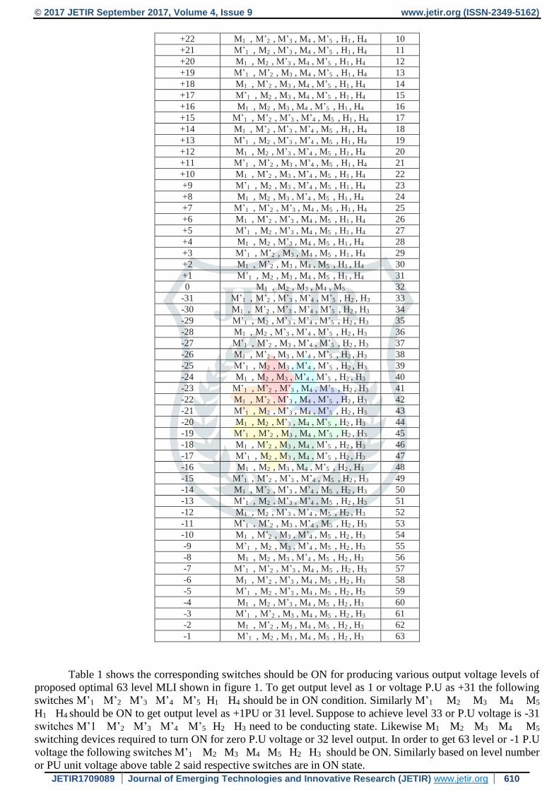
Table 1 shows the corresponding switches should be ON for producing various output voltage levels of
proposed optimal 63 level MLI shown in figure 1. To get output level as 1 or voltage P.U as +31 the following
switches M’1 M’2 M’3 M’4 M’5 H1 H4 should be in ON condition. Similarly M’1 M2 M3 M4 M5
H1 H4 should be ON to get output level as +1PU or 31 level. Suppose to achieve level 33 or P.U voltage is -31
switches M’1 M’2 M’3 M’4 M’5 H2 H3 need to be conducting state. Likewise M1 M2 M3 M4 M5
switching devices required to turn ON for zero P.U voltage or 32 level output. In order to get 63 level or -1 P.U
voltage the following switches M’1 M2 M3 M4 M5 H2 H3 should be ON. Similarly based on level number
or PU unit voltage above table 2 said respective switches are in ON state.

© 2017 JETIR September 2017, Volume 4, Issue 9 www.jetir.org (ISSN-2349-5162)
JETIR1709089 Journal of Emerging Technologies and Innovative Research (JETIR) www.jetir.org 611
III. DESIGN OF PROPOSED INDUCTION MOTOR DRIVE
The proposed MLI is extended as three phase 63 level optimal MLI is with star connection of three
individual single phase 63 optimal MLIs. Hence the designed three phase optimal MLI is feeding with IM with
different controllers for improving drive performance.
Electro Magnetic Torque equation
9 T B /dt d J T Lrre
J-Moment of inertia; 𝝎r –Rotor speed (rad/sec),
B-friction coefficient, TL-Load torque
Induction motor rotor speed equation 10 S-1 sr
Synchronous speed (rad /sec)
1160/2 ss N
Synchronous speed (rev/min)
12/120 pfN s Slip of induction motor
13/ srsS
‘S’ means Slip of induction motor, ‘ f ’ is frequency of supply to stator of IM, ‘p’ means poles number of
magnets.
3.1 Closed loop control of optimal MLI fed IM drive with FLC
The operation of FLC shown in figure 2 depends on linguistic rules IF, AND & THEN operators. The
importance of FLC is to make the induction motor actual current, voltage, speed and torque equals to given
reference values of the same .There are two inputs given to FLC one is error in voltage ‘ΔV’ and second is change
in error voltage ‘ΔE’ and with five membership functions such as ‘NL’ negative low, ‘NH’ negative high, ‘PL’
positive low, ‘PH’ positive high, ‘ZE’ zero equal. By using above said five membership functions, 25 rules are
made in FLC for reducing error between actual and reference values as shown in table 2 for improving
presentation of projected optimal MLI fed induction motor drive. The 63 level MLI feeding induction drive
controlled by FLC block diagram is as shown in figure 4 by replacing ANFIS with FLC. The input to the FLC is
the difference in voltage between reference value and actual value obtained from MLI. The function of FLC
controller is to decrease the steady state and transient error in voltage and the same as input to the induction
motor for improving drive performance.
Figure 2. Fuzzy logic controller implementation in drive
Table 2. Rules for FLC
S.No Rule
1 IF (ΔV is NH) AND (ΔE is NH) THEN (ERROR is ZE)
2 IF (ΔV is NH) AND (ΔE is NL) THEN (ERROR is NL)
3 IF (ΔV is NH) AND (ΔE is ZE) THEN (ERROR is NH)
4 IF (ΔV is NH) AND (ΔE is PL) THEN (ERROR is NH)
5 IF (ΔV is NH) AND (ΔE is PH) THEN (ERROR is NH)
6 IF (ΔV is NL) AND (ΔE is NH) THEN (ERROR is PL)
7 IF (ΔV is NL) AND (ΔE is NL) THEN (ERROR is ZE)
8 IF (ΔV is NL) AND (ΔE is ZE) THEN (ERROR is NL)
9 IF (ΔV is NL) AND (ΔE is PL) THEN (ERROR is NH)
10 IF (ΔV is NL) AND (ΔE is PH) THEN (ERROR is NH)
11 IF (ΔV is ZE) AND (ΔE is NH) THEN (ERROR is PH)
12 IF (ΔV is ZE) AND (ΔE is NL) THEN (ERROR is PL)
13 IF (ΔV is ZE) AND (ΔE is ZE) THEN (ERROR is ZE)
14 IF (ΔV is ZE) AND (ΔE is PL) THEN (ERROR is NL)
15 IF (ΔV is ZE) AND (ΔE is PH) THEN (ERROR is NH)
16 IF (ΔV is PL) AND (ΔE is NH) THEN (ERROR is PH)
17 IF (ΔV is PL) AND (ΔE is NL) THEN (ERROR is PH
18 IF (ΔV is PL) AND (ΔE is ZE) THEN (ERROR is PL)
19 IF (ΔV is PL) AND (ΔE is PL) THEN (ERROR is ZE)
20 IF (ΔV is PL) AND (ΔE is PH) THEN (ERROR is NL)
© 2017 JETIR September 2017, Volume 4, Issue 9 www.jetir.org (ISSN-2349-5162)
JETIR1709089 Journal of Emerging Technologies and Innovative Research (JETIR) www.jetir.org 612
21 IF (ΔV is PH) AND (ΔE is NH) THEN (ERROR is PH)
22 IF (ΔV is PH) AND (ΔE is NL) THEN (ERROR is PH)
23 IF (ΔV is PH) AND (ΔE is ZE) THEN (ERROR is PH)
24 IF (ΔV is PH) AND (ΔE is PL) THEN (ERROR is PL)
25 IF (ΔV is PH) AND (ΔE is PH) THEN (ERROR is ZE)
In the above table 2 ‘ΔV’ means voltage error as input 1; ‘ΔE’ means change in voltage error as input
2,‘ERROR’ means output voltage error.
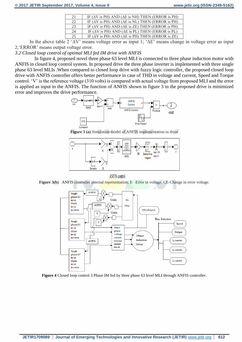
3.2 Closed loop control of optimal MLI fed IM drive with ANFIS
In figure 4, proposed novel three phase 63 level MLI is connected to three phase induction motor with
ANFIS in closed loop control system. In proposed drive the three phase inverter is implemented with three single
phase 63 level MLIs .When compared to closed loop drive with fuzzy logic controller, the proposed closed loop
drive with ANFIS controller offers better performance in case of THD in voltage and current, Speed and Torque
control. ‘V’ is the reference voltage (310 volts) is compared with actual voltage from proposed MLI and the error
is applied as input to the ANFIS. The function of ANFIS shown in figure 3 in the proposed drive is minimized
error and improves the drive performance.
Figure 3 (a) Simulation model of ANFIS implementation in drive
Figure 3(b) ANFIS controller internal representation; E –Error in voltage, CE-Change in error voltage.
Figure 4 Closed loop control 3 Phase IM fed by three phase 63 level MLI through ANFIS controller.
© 2017 JETIR September 2017, Volume 4, Issue 9 www.jetir.org (ISSN-2349-5162)
JETIR1709089 Journal of Emerging Technologies and Innovative Research (JETIR) www.jetir.org 613
IV. RESULTS AND DISCUSSION
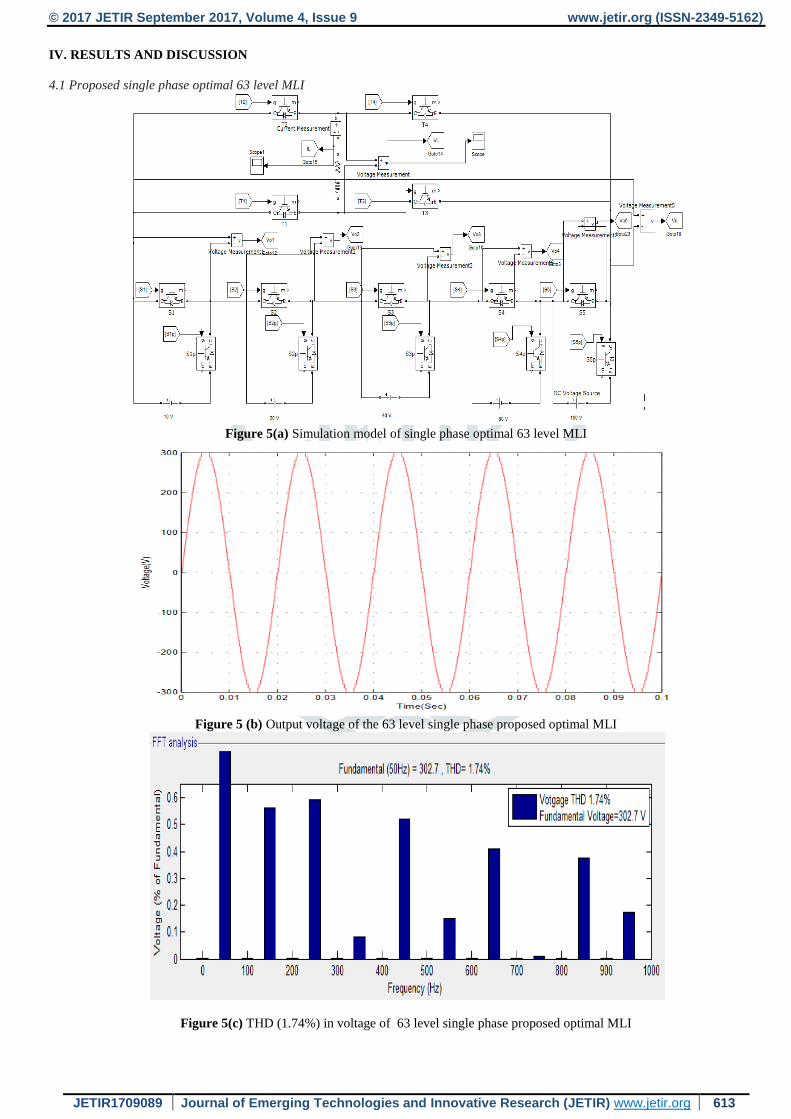
4.1 Proposed single phase optimal 63 level MLI
Figure 5(a) Simulation model of single phase optimal 63 level MLI
Figure 5 (b) Output voltage of the 63 level single phase proposed optimal MLI
Figure 5(c) THD (1.74%) in voltage of 63 level single phase proposed optimal MLI
© 2017 JETIR September 2017, Volume 4, Issue 9 www.jetir.org (ISSN-2349-5162)
JETIR1709089 Journal of Emerging Technologies and Innovative Research (JETIR) www.jetir.org 614
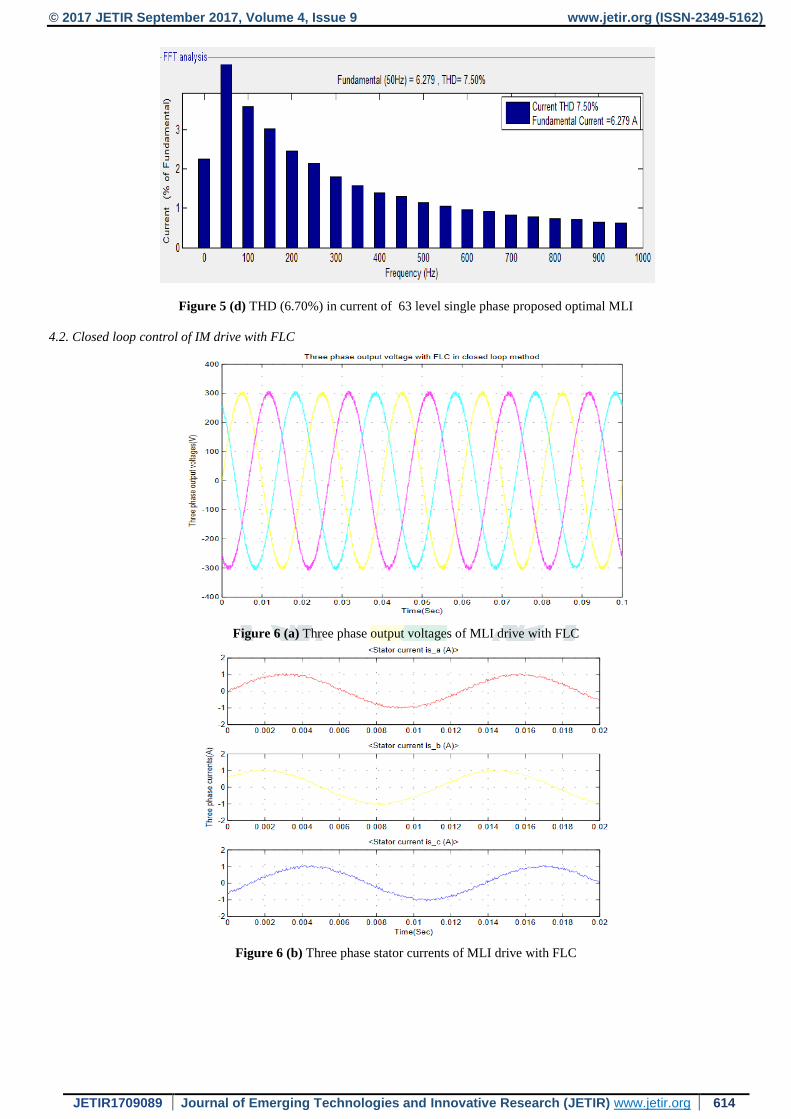
Figure 5 (d) THD (6.70%) in current of 63 level single phase proposed optimal MLI
4.2. Closed loop control of IM drive with FLC
Figure 6 (a) Three phase output voltages of MLI drive with FLC
Figure 6 (b) Three phase stator currents of MLI drive with FLC

© 2017 JETIR September 2017, Volume 4, Issue 9 www.jetir.org (ISSN-2349-5162)
JETIR1709089 Journal of Emerging Technologies and Innovative Research (JETIR) www.jetir.org 615
Figure 6(c) Rotor Speed and torque under no load condition of MLI drive with FLC
Figure 6(d) Rotor Speed and torque under applied load (6 Nm) condition of MLI drive with FLC
Figure 6(e) %THD of three phase voltages of MLI drive with FLC
© 2017 JETIR September 2017, Volume 4, Issue 9 www.jetir.org (ISSN-2349-5162)
JETIR1709089 Journal of Emerging Technologies and Innovative Research (JETIR) www.jetir.org 616
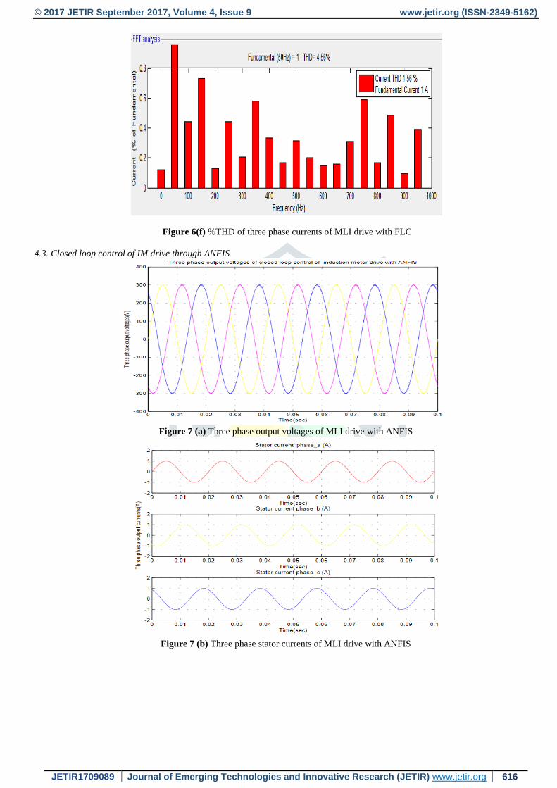
Figure 6(f) %THD of three phase currents of MLI drive with FLC
4.3. Closed loop control of IM drive through ANFIS
Figure 7 (a) Three phase output voltages of MLI drive with ANFIS
Figure 7 (b) Three phase stator currents of MLI drive with ANFIS
© 2017 JETIR September 2017, Volume 4, Issue 9 www.jetir.org (ISSN-2349-5162)
JETIR1709089 Journal of Emerging Technologies and Innovative Research (JETIR) www.jetir.org 617
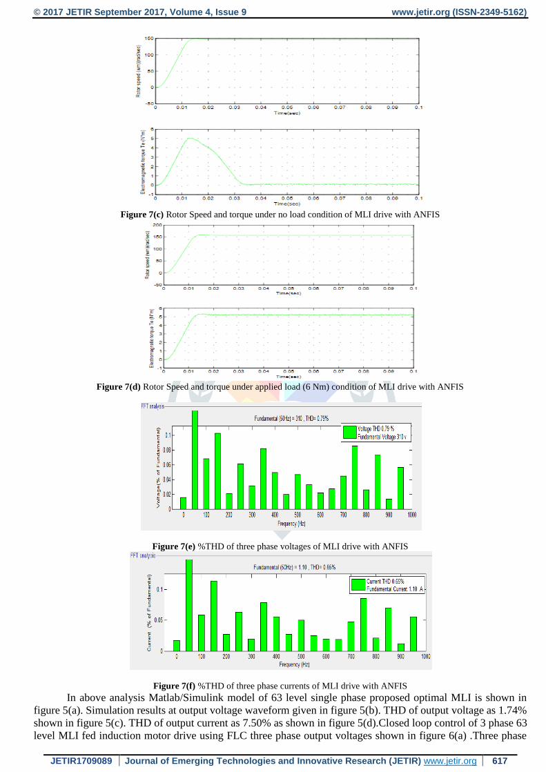
Figure 7(c) Rotor Speed and torque under no load condition of MLI drive with ANFIS
Figure 7(d) Rotor Speed and torque under applied load (6 Nm) condition of MLI drive with ANFIS
Figure 7(e) %THD of three phase voltages of MLI drive with ANFIS
Figure 7(f) %THD of three phase currents of MLI drive with ANFIS
In above analysis Matlab/Simulink model of 63 level single phase proposed optimal MLI is shown in
figure 5(a). Simulation results at output voltage waveform given in figure 5(b). THD of output voltage as 1.74%
shown in figure 5(c). THD of output current as 7.50% as shown in figure 5(d).Closed loop control of 3 phase 63
level MLI fed induction motor drive using FLC three phase output voltages shown in figure 6(a) .Three phase

© 2017 JETIR September 2017, Volume 4, Issue 9 www.jetir.org (ISSN-2349-5162)
JETIR1709089 Journal of Emerging Technologies and Innovative Research (JETIR) www.jetir.org 618
stator currents given in figure 6(b).Speed versus torque under no load condition shown in figure 6(c). Rotor Speed
and torque under applied load (6 Nm) condition shown in figure 6(d) %THD of three phase voltages is 2.38%
shown in figure 6(e). %THD of three phase currents is 4.56% shown in figure 6(f). Closed loop control of 3
phase 63 level MLI fed induction motor drive using ANFIS waveforms regarding -Three phase output voltages
shown in figure 7 (a). Three phase stator currents shown in figure 7 (b). Rotor Speed and torque under no load
condition shown in figure 7 (c). Rotor speed and torque under applied load (6 Nm) condition shown in figure 7
(d). %THD of three phase voltages is 0.79% shown in figure 7 (e). %THD of three phase currents is 0.65% shown
in figure 7(f). Therefore in the proposed drive using ANFIS produces more fundamental voltage and current,
better speed torque control and less THD in voltage and current when compared to drive with FLC in closed loop
control system as shown in table 3.
As the number of levels was increased by using proposed 63 level MLI the output quality also be
improved. The proposed 63 level MLI cost is less than existing high level MLI due to cause of less number of
switching devices and drivers used in proposed MLI. Similarly proposed MLI offers minimum switching, power
losses and low voltage drops. Thus by using this proposed MLI with control of Induction motor drive produces
better performance
Table 3 Comparisons between closed loop 63 level MLI fed Induction motor drive through FLC Controller and ANFIS
Parameters
Closed loop
control of
optimal MLI
fed IM drive
with FLC
Closed loop
control of
optimal MLI
fed IM drive
with ANFIS
%THD Voltage 2.38 0.79
Fundamental voltage(V) 300 310
%THD current 4.56 0.65
Fundamental current(A) 1.00 1.10
Speed(rad/sec) 147 154
Torque (Nm) 5.2 5.8
Table 4 Induction motor specifications
Configuration and Parameters
Mechanical input Torque(Nm)
Rotor type Squirrel cage
Reference frame rotor
Rotor resistance(Rr)) 0.21 Ω
Rotor Inductance(Llr) 1.62mH
Stator resistance(Rs)) 0.66Ω
Stator Inductance(Lls) 1.6mH
Mutual Inductance 38.8mH
Friction factor 0 N-ms
Power(Po) 1.5KW
Voltage(VPh) 310V
Frequency 50 Hz
Inertia(J) 0.08Kgm
Pole Pairs(P) 2
V. CONCLUSION
The proposed three phase optimal 63 level MLI is designed by using three individual single phase multi-
level inverters. Proposed optimal MLI is the asymmetrical type which has been inducted with SPWM control
technique. The extend part of closed loop control method the drive has been controlled and influenced by a FLC
controller after that with ANFIS controller. Simulation results show that proposed drive produces more
fundamental voltage and current, low THD in voltage and current and better speed torque control when it was
controlled by ANFIS.
VI. ACKNOWLEDGMENT
The authors convey deep sense of gratitude to the management of Annamacharya Institute of Technology and
Sciences for helping with required facilities to complete this work.

© 2017 JETIR September 2017, Volume 4, Issue 9 www.jetir.org (ISSN-2349-5162)
JETIR1709089 Journal of Emerging Technologies and Innovative Research (JETIR) www.jetir.org 619
REFERENCES
1. J.Rodriugz,J.s Lai and F.Z Pen.Multilevel inverters A survey of topology, control and applications, IEEE ,vol 49,no 4 ,Aug 2002.
2. J. H. Kim, S.K.Sul, A career based PWM method with optimal switching sequence for a multilevel four-leg voltage source
inverter ,IEEE Trans Ind App, vol, no 4,,july /aug 2008.
3. Sergio Daher, Jürgen, Schmid, Fermando, Multilevel Inverter Topologies for Stan Alone PV System, Jul 2010.
4. Anushuman Shukal,Arindam Ghosh ,Flying-Capacitor-Based Chopper Circuit for DC Capacitor Voltage Balancing in diode
Clamped Multilevel Inverter, vol 13 no 4 2011.
5. Ataollah Mokhberdoran and Ali Ajami, “Symmetric and Asymmetric design of new cascaded multilevel inverter” ieee
transactions on power electronics,vol. 29, no. 12,dec 2014.
6. C.K. Lee, S. Y.Ron Hui,Senior Member, IEEE, and Henry shu- Hung Chung Member, IEEE. A 31 level Cascade Inverter for
Power Applications, IEEE transactions on industrial electronics, vol. 49, no. 3, june 2002.
7. Eduardo E. Espinosa, EEE,A New modulation method for 13 level asymmetric inverter towards minimum THD, IEEE transactions
on industry applications, vol. 50, no. 3, may/june 2014.
8. Mohamed.S, Zaky .A Performance Investigation of a Four - switch Three Phase Inverter-Fed IM Drives at Low Speeds Using
Fuzzy Logic and PI Controllers, IEEE Trans Power electronics.jun 2016.
9. Xingang Fu,and Shuhui Li,Senior .A Novel Neural Network Vector Control Technique for Induction Motor Drive. Dec 2017.
10. Y. V. Siva Reddy, M. Vijaya Kumar, A New Space Vector Pulse width Modulation for Reduction of Common Mode Voltage in
Direct Torque Controlled Induction Motor Drive, Iranian journal electrical and computer engineering, vol. 7, no. 1, winter-
spring 2008.
Top Related