
ZULU MZULU M Radio MODEM Module Radio MODEM...
12
ZULU M ZULU M ZULU M ZULU M DS-ZULUM-1 Radio MODEM Module Radio MODEM Module Radio MODEM Module Radio MODEM Module Applications Applications Applications Applications • Remote Networking • USB/RS232 Cable Replacement • Remote Data Log • Meter Reading The ZULU Modem module is a highly integrated RF Modem and intelligent controller with simple interface to achieve a wireless serial data link for data (upto 38K4bps) over 2KM range. Range may be further extended with suitable antenna. The user interface is standard RS232 style control operating at low voltage. All RF op- eration is automatically controlled (with error checking etc) so the Zulu can be treated as a simple Communications device. Possible applications include one-to-one and multi-node wireless links in applications in- cluding car and building security, EPOS, inventory tracking, remote industrial process monitoring and computer networking. Because of their small size and low power re- quirements this module is ideal for use in portable, battery-powered applications such as hand-held terminals. Part No Part No Part No Part No Description Description Description Description ZULU-M868 Radio Modem Module DIP Package ZULU-M868-SO Radio Modem Module SMT Package Features Features Features Features • Intelligent RF Modem Module • Serial Data Interface with Handshake • Host Data Rates up to 38,400 Baud • RF Data Rates to 56Kbps • Range up to 2Km • Minimal external components • Direct Led Drive Shows Data Flow • 8 User Selectable Channels • Secure Data Protocol • Ultra Low Power 2.2 - 3.6V Operation • CE Compliant for Licence Free Use • 868MHz or 915MHz Versions • 100mW Transmit Power (+20dBm) • Receiver Sensitivity –116dBm
Transcript of ZULU MZULU M Radio MODEM Module Radio MODEM...

ZULU MZULU MZULU MZULU M
DDDDSSSS----ZZZZUUUULLLLUUUUMMMM----1111
Radio MODEM Module Radio MODEM Module Radio MODEM Module Radio MODEM Module
ApplicationsApplicationsApplicationsApplications
•• Remote Networking
• USB/RS232 Cable Replacement
•• Remote Data Log
•• Meter Reading
The ZULU Modem module is a highly integrated RF Modem and intelligent controller
with simple interface to achieve a wireless serial data link for data (upto 38K4bps) over
2KM range. Range may be further extended with suitable antenna.
The user interface is standard RS232 style control operating at low voltage. All RF op-
eration is automatically controlled (with error checking etc) so the Zulu can be treated
as a simple Communications device.
Possible applications include one-to-one and multi-node wireless links in applications in-
cluding car and building security, EPOS, inventory tracking, remote industrial process
monitoring and computer networking. Because of their small size and low power re-
quirements this module is ideal for use in portable, battery-powered applications such
as hand-held terminals.
Part NoPart NoPart NoPart No DescriptionDescriptionDescriptionDescription
ZULU-M868 Radio Modem Module DIP Package
ZULU-M868-SO Radio Modem Module SMT Package
FeaturesFeaturesFeaturesFeatures
• Intelligent RF Modem Module
• Serial Data Interface with Handshake
• Host Data Rates up to 38,400 Baud
• RF Data Rates to 56Kbps
•• Range up to 2Km
•• Minimal external components
• Direct Led Drive Shows Data Flow
• 8 User Selectable Channels
•• Secure Data Protocol
•• Ultra Low Power 2.2 - 3.6V Operation
•• CE Compliant for Licence Free Use
•• 868MHz or 915MHz Versions
•• 100mW Transmit Power (+20dBm)
•• Receiver Sensitivity –116dBm

ZULU ModemZULU ModemZULU ModemZULU Modem
DDDDSSSS----ZZZZUUUULLLLUUUUMMMM----1111
PinoutPinoutPinoutPinout
Pin DescriptionPin DescriptionPin DescriptionPin Description
Pin NoPin NoPin NoPin No NameNameNameName DirectionDirectionDirectionDirection DescriptionDescriptionDescriptionDescription
1 ANT In Antenna Input / Output 50ohm Impedance
2, 15 GND In Connect to Ground
3-5,
11,
13-14,
20-24
N/C N/A Unused Leave Disconnected.
6 RX In (Low Level RS232) Data in
7 TX Out Low Level RS232 Data Out
8 LINK In Connect to LINK on Pin 28
9 CTS Out Low Level RS232 CTS
10 RTS In Low Level RS232 RTS
12 RESET In Device Reset Input (Tie High via 10K Resistor)
16 Vcc In +2.2-3.6v
17-18 DR1-DR2 In Host Data Rate selection.
19 WRE In
When High configuration data is held in EEPROM.
When Low configuration data is held in volatile memory
and lost on power cycle.
25 PD In Power down mode. Take low to enter Sleep mode
26 TX LED Out RF TX LED indicator
27 RX LED Out RF RX LED indicator
28 LINK Out Connect to LINK on Pin 8
29-30 XTAL1-2 In Connect 30MHz XTAL here to drive RF Circuit
ZULU ModemZULU ModemZULU ModemZULU Modem
DDDDSSSS----ZZZZUUUULLLLUUUUMMMM----1111
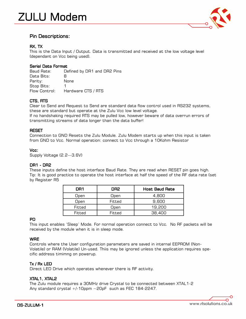
Pin Descriptions:Pin Descriptions:Pin Descriptions:Pin Descriptions:
RX, TX RX, TX RX, TX RX, TX
This is the Data Input / Output. Data is transmitted and received at the low voltage level
(dependant on Vcc being used).
Serial Data FormatSerial Data FormatSerial Data FormatSerial Data Format
Baud Rate: Defined by DR1 and DR2 Pins
Data Bits: 8
Parity: None
Stop Bits: 1
Flow Control: Hardware CTS / RTS
CTS, RTSCTS, RTSCTS, RTSCTS, RTS
Clear to Send and Request to Send are standard data flow control used in RS232 systems,
these are standard but operate at the Zulu Vcc low level voltage.
If no handshaking required RTS may be pulled low, however beware of data overrun errors of
transmitting streams of data longer than the data buffer!
RESETRESETRESETRESET
Connection to GND Resets the Zulu Module. Zulu Modem starts up when this input is taken
from GND to Vcc. Normal operation: connect to Vcc through a 10Kohm Resistor
Vcc:Vcc:Vcc:Vcc:
Supply Voltage (2.2—3.6V)
DR1 DR1 DR1 DR1 ---- DR2 DR2 DR2 DR2
These inputs define the host interface Baud Rate. They are read when RESET pin goes high.
Tip: It is good practice to operate the host interface at half the speed of the RF data rate (set
by Register R5
PDPDPDPD
This input enables ‘Sleep’ Mode. For normal operation connect to Vcc. No RF packets will be
received by the module when it is in sleep mode.
WREWREWREWRE
Controls where the User configuration parameters are saved in internal EEPROM (Non-
Volatile) or RAM (Volatile) Un-used. Thiis may be ignored unless the application requires spe-
cific address timimng on powerup.
Tx / Rx LEDTx / Rx LEDTx / Rx LEDTx / Rx LED
Direct LED Drive which operates whenever there is RF activity.
XTAL1, XTAL2 XTAL1, XTAL2 XTAL1, XTAL2 XTAL1, XTAL2
The Zulu module requires a 30MHz drive Crystal to be connected between XTAL1-2
Any standard crystal +/-10ppm ~20pF such as FEC 184-2247.
DR1DR1DR1DR1 DR2DR2DR2DR2 Host Baud RateHost Baud RateHost Baud RateHost Baud Rate
Open Open 4,800
Open Fitted 9,600
Fitted Open 19,200
Fitted Fitted 38,400
ZULU ModemZULU ModemZULU ModemZULU Modem
DDDDSSSS----ZZZZUUUULLLLUUUUMMMM----1111
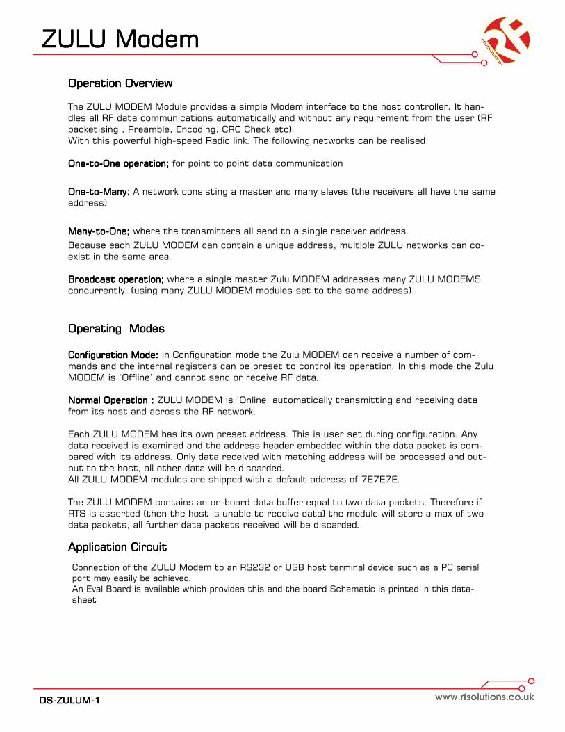
Operation OverviewOperation OverviewOperation OverviewOperation Overview
The ZULU MODEM Module provides a simple Modem interface to the host controller. It han-
dles all RF data communications automatically and without any requirement from the user (RF
packetising , Preamble, Encoding, CRC Check etc).
With this powerful high-speed Radio link. The following networks can be realised;
OneOneOneOne----totototo----One operation; One operation; One operation; One operation; for point to point data communication
OneOneOneOne----totototo----ManyManyManyMany; A network consisting a master and many slaves (the receivers all have the same
address)
ManyManyManyMany----totototo----One; One; One; One; where the transmitters all send to a single receiver address.
Because each ZULU MODEM can contain a unique address, multiple ZULU networks can co-
exist in the same area.
Broadcast operation; Broadcast operation; Broadcast operation; Broadcast operation; where a single master Zulu MODEM addresses many ZULU MODEMS
concurrently. (using many ZULU MODEM modules set to the same address),
Operating ModesOperating ModesOperating ModesOperating Modes
Configuration Mode: Configuration Mode: Configuration Mode: Configuration Mode: In Configuration mode the Zulu MODEM can receive a number of com-
mands and the internal registers can be preset to control its operation. In this mode the Zulu
MODEM is ‘Offline’ and cannot send or receive RF data.
Normal Operation : Normal Operation : Normal Operation : Normal Operation : ZULU MODEM is ’Online’ automatically transmitting and receiving data
from its host and across the RF network.
Each ZULU MODEM has its own preset address. This is user set during configuration. Any
data received is examined and the address header embedded within the data packet is com-
pared with its address. Only data received with matching address will be processed and out-
put to the host, all other data will be discarded.
All ZULU MODEM modules are shipped with a default address of 7E7E7E.
The ZULU MODEM contains an on-board data buffer equal to two data packets. Therefore if
RTS is asserted (then the host is unable to receive data) the module will store a max of two
data packets, all further data packets received will be discarded.
Application CircuitApplication CircuitApplication CircuitApplication Circuit
Connection of the ZULU Modem to an RS232 or USB host terminal device such as a PC serial
port may easily be achieved.
An Eval Board is available which provides this and the board Schematic is printed in this data-
sheet
ZULU ModemZULU ModemZULU ModemZULU Modem
DDDDSSSS----ZZZZUUUULLLLUUUUMMMM----1111
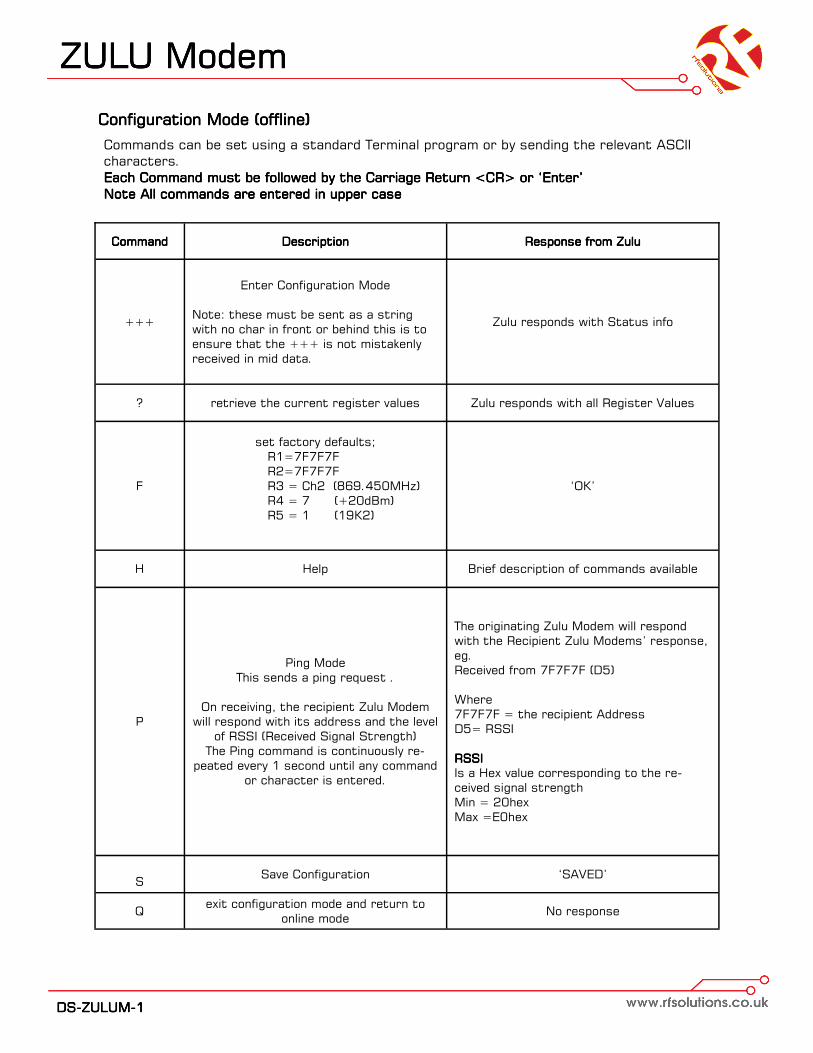
Configuration Mode (offline)Configuration Mode (offline)Configuration Mode (offline)Configuration Mode (offline)
Commands can be set using a standard Terminal program or by sending the relevant ASCII
characters.
Each Command must be followed by the Carriage Return <CR> or ‘Enter’Each Command must be followed by the Carriage Return <CR> or ‘Enter’Each Command must be followed by the Carriage Return <CR> or ‘Enter’Each Command must be followed by the Carriage Return <CR> or ‘Enter’
Note All commands are entered in upper caseNote All commands are entered in upper caseNote All commands are entered in upper caseNote All commands are entered in upper case
Command Command Command Command DescriptionDescriptionDescriptionDescription
+++
Enter Configuration Mode
Note: these must be sent as a string
with no char in front or behind this is to
ensure that the +++ is not mistakenly
received in mid data.
? retrieve the current register values
F
set factory defaults;
R1=7F7F7F
R2=7F7F7F
R3 = Ch2 (869.450MHz)
R4 = 7 (+20dBm)
R5 = 1 (19K2)
H Help
S Save Configuration
Q exit configuration mode and return to
online mode
Response from ZuluResponse from ZuluResponse from ZuluResponse from Zulu
Zulu responds with Status info
Zulu responds with all Register Values
‘OK’
Brief description of commands available
‘SAVED’
No response
P
Ping Mode
This sends a ping request .
On receiving, the recipient Zulu Modem
will respond with its address and the level
of RSSI (Received Signal Strength)
The Ping command is continuously re-
peated every 1 second until any command
or character is entered.
The originating Zulu Modem will respond
with the Recipient Zulu Modems’ response,
eg.
Received from 7F7F7F (D5)
Where
7F7F7F = the recipient Address
D5= RSSI
RSSI RSSI RSSI RSSI
Is a Hex value corresponding to the re-
ceived signal strength
Min = 20hex
Max =E0hex
ZULU ModemZULU ModemZULU ModemZULU Modem
DDDDSSSS----ZZZZUUUULLLLUUUUMMMM----1111
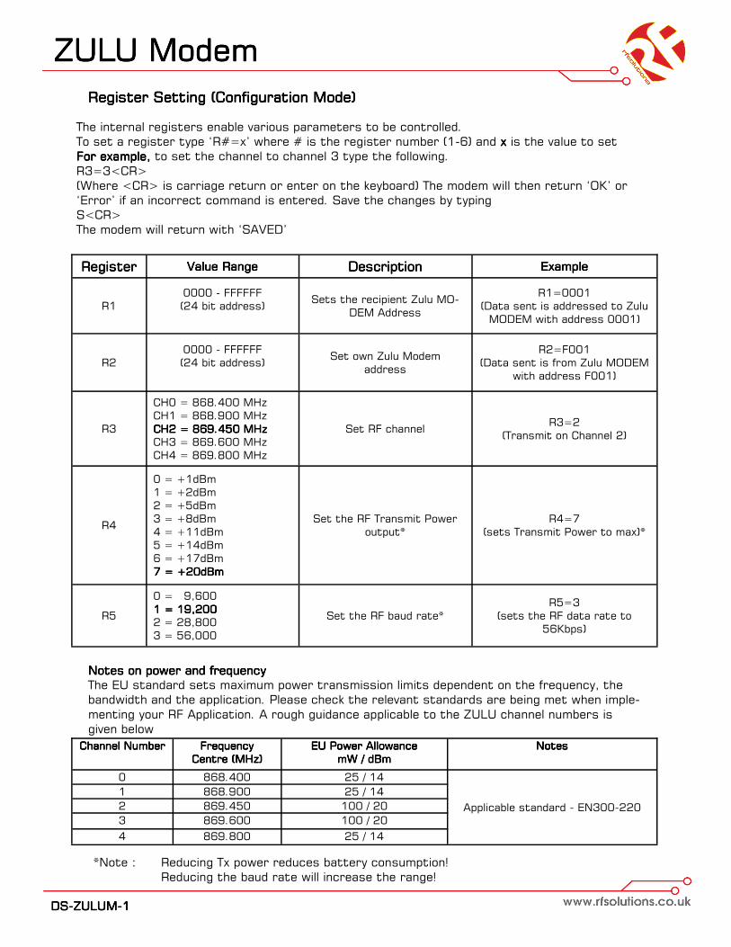
Register Setting (Configuration Mode)Register Setting (Configuration Mode)Register Setting (Configuration Mode)Register Setting (Configuration Mode)
The internal registers enable various parameters to be controlled.
To set a register type ‘R#=x’ where # is the register number (1-6) and xxxx is the value to set
For example, For example, For example, For example, to set the channel to channel 3 type the following.
R3=3<CR>
(Where <CR> is carriage return or enter on the keyboard) The modem will then return ‘OK’ or
‘Error’ if an incorrect command is entered. Save the changes by typing
S<CR>
The modem will return with ‘SAVED’
RegisterRegisterRegisterRegister Value RangeValue RangeValue RangeValue Range DescriptionDescriptionDescriptionDescription ExampleExampleExampleExample
R1
0000 - FFFFFF
(24 bit address)
Sets the recipient Zulu MO-
DEM Address
R1=0001
(Data sent is addressed to Zulu
MODEM with address 0001)
R2
0000 - FFFFFF
(24 bit address)
Set own Zulu Modem
address
R2=F001
(Data sent is from Zulu MODEM
with address F001)
R3
CH0 = 868.400 MHz
CH1 = 868.900 MHz
CH2 = 869.450 MHzCH2 = 869.450 MHzCH2 = 869.450 MHzCH2 = 869.450 MHz
CH3 = 869.600 MHz
CH4 = 869.800 MHz
Set RF channel R3=2
(Transmit on Channel 2)
R4
0 = +1dBm
1 = +2dBm
2 = +5dBm
3 = +8dBm
4 = +11dBm
5 = +14dBm
6 = +17dBm
7 = +20dBm7 = +20dBm7 = +20dBm7 = +20dBm
Set the RF Transmit Power
output*
R4=7
(sets Transmit Power to max)*
R5
0 = 9,600
1 = 19,2001 = 19,2001 = 19,2001 = 19,200
2 = 28,800
3 = 56,000
Set the RF baud rate*
R5=3
(sets the RF data rate to
56Kbps)
*Note : Reducing Tx power reduces battery consumption!
Reducing the baud rate will increase the range!
Channel NumberChannel NumberChannel NumberChannel Number Frequency Frequency Frequency Frequency
Centre (MHz)Centre (MHz)Centre (MHz)Centre (MHz)
EU Power AllowanceEU Power AllowanceEU Power AllowanceEU Power Allowance
mW / dBmmW / dBmmW / dBmmW / dBm
NotesNotesNotesNotes
0 868.400 25 / 14
1 868.900 25 / 14
2 869.450 100 / 20
3 869.600 100 / 20
4 869.800 25 / 14
Applicable standard - EN300-220
Notes on power and frequencyNotes on power and frequencyNotes on power and frequencyNotes on power and frequency
The EU standard sets maximum power transmission limits dependent on the frequency, the
bandwidth and the application. Please check the relevant standards are being met when imple-
menting your RF Application. A rough guidance applicable to the ZULU channel numbers is
given below
ZULU ModemZULU ModemZULU ModemZULU Modem
DDDDSSSS----ZZZZUUUULLLLUUUUMMMM----1111
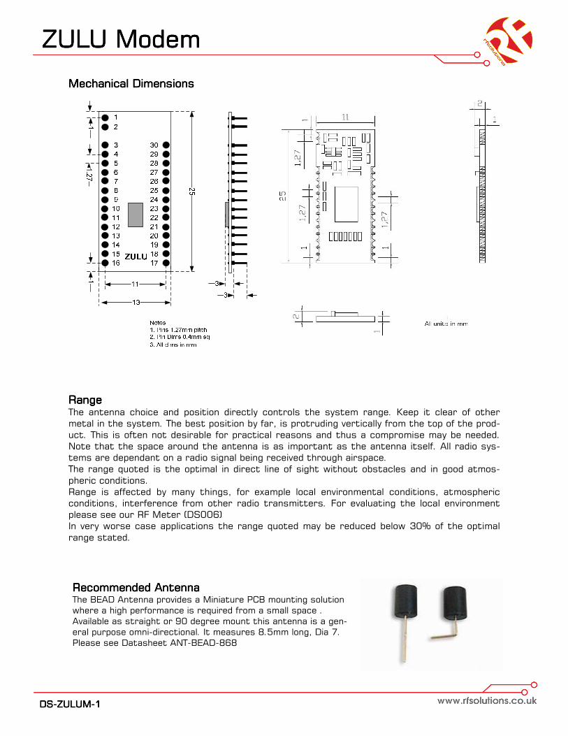
RangeRangeRangeRange The antenna choice and position directly controls the system range. Keep it clear of other
metal in the system. The best position by far, is protruding vertically from the top of the prod-
uct. This is often not desirable for practical reasons and thus a compromise may be needed.
Note that the space around the antenna is as important as the antenna itself. All radio sys-
tems are dependant on a radio signal being received through airspace.
The range quoted is the optimal in direct line of sight without obstacles and in good atmos-
pheric conditions.
Range is affected by many things, for example local environmental conditions, atmospheric
conditions, interference from other radio transmitters. For evaluating the local environment
please see our RF Meter (DS006)
In very worse case applications the range quoted may be reduced below 30% of the optimal
range stated.
Mechanical Dimensions Mechanical Dimensions Mechanical Dimensions Mechanical Dimensions
Recommended AntennaRecommended AntennaRecommended AntennaRecommended Antenna The BEAD Antenna provides a Miniature PCB mounting solution
where a high performance is required from a small space .
Available as straight or 90 degree mount this antenna is a gen-
eral purpose omni-directional. It measures 8.5mm long, Dia 7.
Please see Datasheet ANT-BEAD-868

ZULU ModemZULU ModemZULU ModemZULU Modem
DDDDSSSS----ZZZZUUUULLLLUUUUMMMM----1111
Technical SpecificationsTechnical SpecificationsTechnical SpecificationsTechnical Specifications
Absolute MaximumsAbsolute MaximumsAbsolute MaximumsAbsolute Maximums:::: Temperature RangeTemperature RangeTemperature RangeTemperature Range: Storage –50 to +125oC.
Weight: SMT version 7grams, DIP Part 13grams
DC CharacteristicsDC CharacteristicsDC CharacteristicsDC Characteristics
ParameterParameterParameterParameter MinMinMinMin MaxMaxMaxMax UnitsUnitsUnitsUnits
Supply Voltage -0.3 3.6 V
Voltage on any Input -0.3 Vcc+0. V
Max Input power (thro Antenna) +10 dBm
ParameterParameterParameterParameter MinMinMinMin TypicalTypicalTypicalTypical MaxMaxMaxMax UnitsUnitsUnitsUnits
Supply Voltage 2.2 3.6 V
Operating Temperature -40 +85 oC
Zulu Tx Supply Current:
When Transmitting
When sleeping
100
1
mA
uA
Zulu Rx Supply Current:
When Receiving
When sleeping
18.5
1
mA
uA
AC CharacteristicsAC CharacteristicsAC CharacteristicsAC Characteristics
ParameterParameterParameterParameter MinMinMinMin TypicalTypicalTypicalTypical MaxMaxMaxMax UnitsUnitsUnitsUnits
Operating Frequency—see freq channel setting 868 870 MHz
Operating Temperature -40 +85 oC
Deviation 45 KHz
Zulu Tx—Rx FSK Raw RF Data Rate 256 Kbps
Zulu Rx Sensitivity -116 dBm
Band width per channel 100 KHz
Zulu Tx MAX Output Power +20 dBm

ZULU ModemZULU ModemZULU ModemZULU Modem
DDDDSSSS----ZZZZUUUULLLLUUUUMMMM----1111
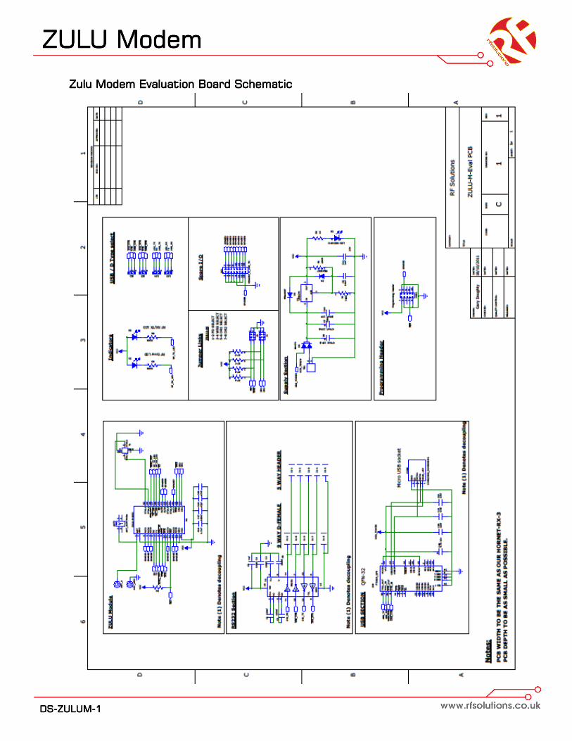
Zulu Modem Evaluation BoardZulu Modem Evaluation BoardZulu Modem Evaluation BoardZulu Modem Evaluation Board The ZULU EVAL Board provides a ready made platform which can be used to
demonstrate the capabilities of ZULU Modem Modules providing ready made
RS232 and USB Modem Solutions.
Part NoPart NoPart NoPart No DescriptionDescriptionDescriptionDescription
ZULUEVAL-M Zulu Modem Eval Board
PSU-12V100MAUK Plugtop Power Supply 12V 100mA
FeaturesFeaturesFeaturesFeatures
•• Direct Connection to RS232 / USB
• 9-12Vdc Power in Screw Terminal
• LED Indication Transmit / Receiver
• User Config Jumper Links

ZULU ModemZULU ModemZULU ModemZULU Modem
DDDDSSSS----ZZZZUUUULLLLUUUUMMMM----1111
EVAL Board ConfigurationEVAL Board ConfigurationEVAL Board ConfigurationEVAL Board Configuration
Power Requirements: 9Power Requirements: 9Power Requirements: 9Power Requirements: 9----15Vdc15Vdc15Vdc15Vdc
Weight: 27grams, Dimensions:
Config LinksConfig LinksConfig LinksConfig Links
USB / D Links (LK2,3,4,5)USB / D Links (LK2,3,4,5)USB / D Links (LK2,3,4,5)USB / D Links (LK2,3,4,5) For USB connect all Links from Centre to ’USB’ Side
For RS232 connect all Links from Centre to ’RS232’ Side
Antenna ConnectorAntenna ConnectorAntenna ConnectorAntenna Connector
The connector is a 4mm Screw Thread (Part NO: SCRTM4RA)
Power ConnectionPower ConnectionPower ConnectionPower Connection
Power is only required for RS232 comms, USB connection provides power automatically
Host Terminal SoftwareHost Terminal SoftwareHost Terminal SoftwareHost Terminal Software
Connection to Host is via the micro-USB Cable or RS232 Cable.
Any Terminal emulation program can interface the Eval board, one we have found to be easy to
use and powerful is ‘Terminal’
This can be downloaded from :
https://sites.google.com/site/terminalbpp/
Notes for Optimising RangeNotes for Optimising RangeNotes for Optimising RangeNotes for Optimising Range
In order to obtain the best range
1. Use max RF Transmit power (set Register R4 = 7)
2. use the slowest RF comms Rate (set Register R5 = 0)
3. Power the Eval boards from 12V (don't rely on the USB power)
4. Consider upgrading the antennas to models with gain.
Link RefLink RefLink RefLink Ref NameNameNameName When FittedWhen FittedWhen FittedWhen Fitted When OpenWhen OpenWhen OpenWhen Open
PD Power Down Modem is Placed in Sleep Mode Normal Operation
WRE Write Enable On each Power up with Zulu Con-
fig setting are reset to defaults
On Power up Zulu Config settings
remain unchanged
DR1
DR2
Sets Host
Baud
DR1 DR2
Open Open
Open Fitted
Fitted Open
Fitted Fitted
Baud Rate:
4800
9600
19200
38400
ZULU ModemZULU ModemZULU ModemZULU Modem
DDDDSSSS----ZZZZUUUULLLLUUUUMMMM----1111
Zulu Modem Evaluation Board SchematicZulu Modem Evaluation Board SchematicZulu Modem Evaluation Board SchematicZulu Modem Evaluation Board Schematic

ZULU ModemZULU ModemZULU ModemZULU Modem
Whilst the information in this document is believed to be correct at the time of issue, RF Solutions Ltd does not accept any liability whatsoever for its accuracy,
adequacy or completeness. No express or implied warranty or representation is given relating to the information contained in this document. RF Solutions Ltd
reserves the right to make changes and improvements to the product(s) described herein without notice. Buyers and other users should determine for them-
selves the suitability of any such information or products for their own particular requirements or specification(s). RF Solutions Ltd shall not be liable for any loss
or damage caused as a result of user’s own determination of how to deploy or use RF Solutions Ltd’s products. Use of RF Solutions Ltd products or components
in life support and/or safety applications is not authorised except with express written approval. No licences are created, implicitly or otherwise, under any of RF
Solutions Ltd’s intellectual property rights. Liability for loss or damage resulting or caused by reliance on the information contained herein or from the use of the
product (including liability resulting from negligence or where RF Solutions Ltd was aware of the possibility of such loss or damage arising) is excluded. This will not
operate to limit or restrict RF Solutions Ltd’s liability for death or personal injury resulting from its negligence.
Reader ResponseReader ResponseReader ResponseReader Response It is our intention to provide you with the best documentation possible to ensure successful
use of your RF Solutions product.
If you wish to provide your comments on organization, clarity, subject matter, and ways in
which our documentation can better serve you, please email us your comments to the Tech-
nical Publications Manager
Application:
Would you like a reply? Y / N
Datasheet: DS-ZULUModem-1
Questions:
1. What are the best features of this document?
2. How does this document meet your hardware and software development needs?
3. Do you find the organization of this document easy to follow? If not, why?
4. What additions to the document do you think would enhance the structure and subject?
5. What deletions from the document could be made without affecting the usefulness?
6. Is there any incorrect or misleading information (what and where)?
7. How would you improve this document?
R F Solutions Ltd.,R F Solutions Ltd.,R F Solutions Ltd.,R F Solutions Ltd.,
Unit 21, Cliffe Industrial Estate,Unit 21, Cliffe Industrial Estate,Unit 21, Cliffe Industrial Estate,Unit 21, Cliffe Industrial Estate,
Lewes, E. Sussex. BN8 6JL. England.Lewes, E. Sussex. BN8 6JL. England.Lewes, E. Sussex. BN8 6JL. England.Lewes, E. Sussex. BN8 6JL. England.
Email : Email : Email : Email : [email protected]@[email protected]@rfsolutions.co.uk http://www.rfsolutions.co.ukhttp://www.rfsolutions.co.ukhttp://www.rfsolutions.co.ukhttp://www.rfsolutions.co.uk
Tel Sales: Tel Sales: Tel Sales: Tel Sales: 01273 898 02001273 898 02001273 898 02001273 898 020
Tel Technical: Tel Technical: Tel Technical: Tel Technical: 01273 898 00701273 898 00701273 898 00701273 898 007
Tel Gen Enq: Tel Gen Enq: Tel Gen Enq: Tel Gen Enq: 01273 898 00001273 898 00001273 898 00001273 898 000
RF Solutions Ltd. Recycling NoticeRF Solutions Ltd. Recycling NoticeRF Solutions Ltd. Recycling NoticeRF Solutions Ltd. Recycling Notice
Meets the following EC Directives:
DO NOT DO NOT DO NOT DO NOT Discard with normal waste, please recycle.
ROHS Directive 2002/95/ECROHS Directive 2002/95/ECROHS Directive 2002/95/ECROHS Directive 2002/95/EC
Specifies certain limits for hazardous substances.
WEEE Directive 2002/96/ECWEEE Directive 2002/96/ECWEEE Directive 2002/96/ECWEEE Directive 2002/96/EC
Waste electrical & electronic equipment. This product must be disposed of through a licensed
WEEE collection point. RF Solutions Ltd., fulfils its WEEE obligations by membership of an ap-
proved compliance scheme.