ZoneZ Network Manual - Touch-Plate Lighting...
20
ZoneZ Network Manual
Transcript of ZoneZ Network Manual - Touch-Plate Lighting...

ZoneZ Net work M anual

Table O f Contents
Preparation .. . . . . . . . . . . . . . . . . . . . . . . . . . . . . . . . . . . . . . . . . . . . . . . . . . . . . . . . . . . . . . . . . . . . . . . . . . . . . . . . . . . . . . . . . . . . . . . . . . . . . . . . . . . . . . . . . . . . . . . . . . . . . . . . . . . . . . . . . . . . . .2
ZNZ-ZN Overview .. . . . . . . . . . . . . . . . . . . . . . . . . . . . . . . . . . . . . . . . . . . . . . . . . . . . . . . . . . . . . . . . . . . . . . . . . . . . . . . . . . . . . . . . . . . . . . . . . . . . . . . . . . . . . . . . . . . . . . . . . . . . . . . . . . .3
Installation Notes . . . . . . . . . . . . . . . . . . . . . . . . . . . . . . . . . . . . . . . . . . . . . . . . . . . . . . . . . . . . . . . . . . . . . . . . . . . . . . . . . . . . . . . . . . . . . . . . . . . . . . . . . . . . . . . . . . . . . . . . . . . . . . . . . . .4
Retrofitting an Existing System .. . . . . . . . . . . . . . . . . . . . . . . . . . . . . . . . . . . . . . . . . . . . . . . . . . . . . . . . . . . . . . . . . . . . . . . . . . . . . . . . . . . . . . . . . . . . . . . . . . . . . . . . . . . .5
Line Voltage Wiring and Connections . . . . . . . . . . . . . . . . . . . . . . . . . . . . . . . . . . . . . . . . . . . . . . . . . . . . . . . . . . . . . . . . . . . . . . . . . . . . . . . . . . . . . . . . . . . . . . . . . . .6
Contact Closure Switch Wiring and Connections (Relays 1-6) . . . . . . . . . . . . . . . . . . . . . . . . . . . . . . . . . . . . . . . . . . . . . . . . . . . . . . . . . .7
Contact Closure Switch Wiring and Connections (Grouping) . . . . . . . . . . . . . . . . . . . . . . . . . . . . . . . . . . . . . . . . . . . . . . . . . . . . . . . . . . . .8
Contact Closure Switch Wiring and Connections (LED) . . . . . . . . . . . . . . . . . . . . . . . . . . . . . . . . . . . . . . . . . . . . . . . . . . . . . . . . . . . . . . . . . . . . .9
Programming Interface Explanations . . . . . . . . . . . . . . . . . . . . . . . . . . . . . . . . . . . . . . . . . . . . . . . . . . . . . . . . . . . . . . . . . . . . . . . . . . . . . . . . . . . . . . . . . . . . . . . . .10
Programming Group Functions . . . . . . . . . . . . . . . . . . . . . . . . . . . . . . . . . . . . . . . . . . . . . . . . . . . . . . . . . . . . . . . . . . . . . . . . . . . . . . . . . . . . . . . . . . . . . . . . . . . . . . . . . . .11
Programming LED Functions . . . . . . . . . . . . . . . . . . . . . . . . . . . . . . . . . . . . . . . . . . . . . . . . . . . . . . . . . . . . . . . . . . . . . . . . . . . . . . . . . . . . . . . . . . . . . . . . . . . . . . . . . . . . . . .12
Address Dip Switches . . . . . . . . . . . . . . . . . . . . . . . . . . . . . . . . . . . . . . . . . . . . . . . . . . . . . . . . . . . . . . . . . . . . . . . . . . . . . . . . . . . . . . . . . . . . . . . . . . . . . . . . . . . . . . . . . . . . . . . . . . .13
Option Dip Switches . . . . . . . . . . . . . . . . . . . . . . . . . . . . . . . . . . . . . . . . . . . . . . . . . . . . . . . . . . . . . . . . . . . . . . . . . . . . . . . . . . . . . . . . . . . . . . . . . . . . . . . . . . . . . . . . . . . . . . . . . . . . . .14
Termination Dip Switches . . . . . . . . . . . . . . . . . . . . . . . . . . . . . . . . . . . . . . . . . . . . . . . . . . . . . . . . . . . . . . . . . . . . . . . . . . . . . . . . . . . . . . . . . . . . . . . . . . . . . . . . . . . . . . . . . . . .14
LED Intensity Dip Switches .. . . . . . . . . . . . . . . . . . . . . . . . . . . . . . . . . . . . . . . . . . . . . . . . . . . . . . . . . . . . . . . . . . . . . . . . . . . . . . . . . . . . . . . . . . . . . . . . . . . . . . . . . . . . . . . . . .14
Troubleshooting Guide . . . . . . . . . . . . . . . . . . . . . . . . . . . . . . . . . . . . . . . . . . . . . . . . . . . . . . . . . . . . . . . . . . . . . . . . . . . . . . . . . . . . . . . . . . . . . . . . . . . . . . . . . . . . . . . . . . . . . . . .15
Frequently Asked Questions . . . . . . . . . . . . . . . . . . . . . . . . . . . . . . . . . . . . . . . . . . . . . . . . . . . . . . . . . . . . . . . . . . . . . . . . . . . . . . . . . . . . . . . . . . . . . . . . . . . . . . . . . . . . . . . . .16
1830 Wayne Trace l For t Wayne, I ndiana 46803 l 1 .260.426.1565 l w w w.touchplate.com
Page 2w w w.touchplate.com
Touch-Plate® L ight ing ControlsZoneZ Net work Manual
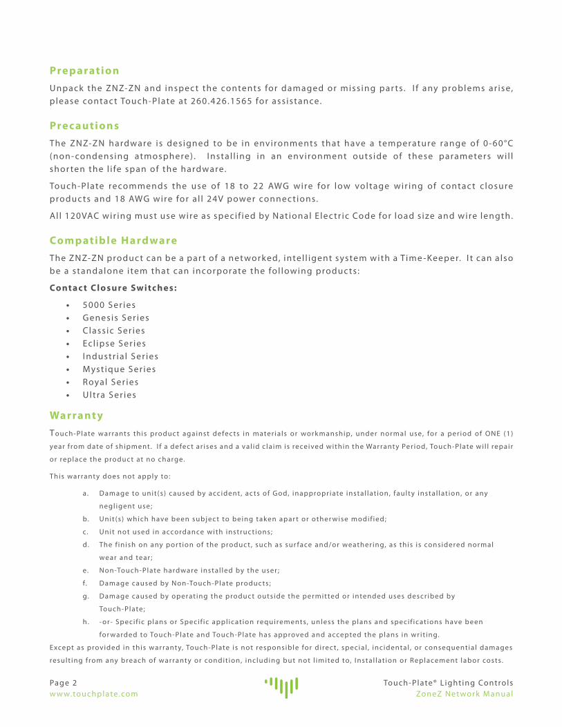
PreparationUnpack the ZNZ-ZN and inspec t the contents for damaged or miss ing par ts . I f any problems ar ise, p lease contac t Touch-Plate at 260.426.1565 for ass istance.
Prec autionsThe ZNZ-ZN hardware is des igned to be in environments that have a temperature range of 0-60°C (non- condensing atmosphere) . I nsta l l ing in an environment outs ide of these parameters wi l l shor ten the l i fe span of the hardware.
Touch-Plate recommends the use of 18 to 22 AWG wire for low voltage wir ing of contac t c losure produc ts and 18 AWG wire for a l l 24V power connec t ions.
Al l 120VAC wir ing must use wire as speci f ied by Nat ional E lec tr ic Code for load s ize and wire length.
Compatible HardwareThe ZNZ-ZN produc t can be a par t of a net worked, intel l igent system with a Time -Keeper. I t can a lso be a standalone i tem that can incorporate the fol lowing produc ts :
Contac t Closure Switches:
• 5000 Ser ies • Genesis Ser ies • Class ic Ser ies • Ecl ipse Ser ies • I ndustr ia l Ser ies • M yst ique Ser ies • Royal Ser ies • Ultra Ser ies
Warrant yT ouch-Plate warrants this produc t against defec ts in mater ia ls or work manship, under normal use, for a per iod of ONE (1)
year f rom date of shipment. I f a defec t ar ises and a val id c la im is received within the Warrant y Per iod, Touch-Plate wi l l repair
or replace the produc t at no charge.
This warrant y does not apply to :
a . Damage to unit (s ) caused by accident , ac ts of God, inappropr iate insta l lat ion, fault y insta l lat ion, or any
negl igent use ;
b. Unit (s ) which have been subjec t to being taken apar t or other wise modif ied;
c. Unit not used in accordance with instruc t ions ;
d. The f in ish on any por t ion of the produc t , such as sur face and/or weather ing, as this i s considered normal
wear and tear ;
e. Non-Touch-Plate hardware insta l led by the user ;
f. Damage caused by Non-Touch-Plate produc ts ;
g. Damage caused by operat ing the produc t outs ide the permitted or intended uses descr ibed by
Touch-Plate ;
h . - or- Speci f ic p lans or Speci f ic appl icat ion requirements, unless the plans and speci f icat ions have been
for warded to Touch-Plate and Touch-Plate has approved and accepted the plans in wr i t ing.
Except as provided in this warrant y, Touch-Plate is not responsible for d i rec t , specia l , inc idental , or consequentia l damages
result ing f rom any breach of warrant y or condit ion, inc luding but not l imited to, I nsta l lat ion or Replacement labor costs.

ALU D
ALU F
Touch-Plate® L ight ing ControlsZoneZ Net work Manual
Page 3w w w.touchplate.com
ZNZ-ZN O ver viewThe ZNZ-ZN is the ef for t less l ight ing solut ion that a l lows for s imple group control .
The ZNZ-ZN has the fol lowing opt ions :
RS485 Connec t ion to Time -Keeper Master Control ler
Terminat ion DIP Switches
Programming I nter face
Contac t Closure Switch I nputs
Group I nputs
LED Outputs
Pi lot Voltage Sett ings
O ther Func t ions DIP Switches
Address DIP Switches
Pi lot I ntensit y DIP Switches
E
F
A
B
C
D
G
H
I
A B
C
D
E
F
G
H
I
J
J

Page 4w w w.touchplate.com
Touch-Plate® L ight ing ControlsZoneZ Net work Manual
I nstal lation NotesThe ZNZ-ZN has re lays which can be removed f rom the system i f they ever need to be replaced. Use the fol lowing diagram and instruc t ions on how to remove the re lay boards f rom the system.
I nser t f lathead screwdr iver into the s lot on the din ra i l c l ip.
Us ing the screwdr iver, pr y the c l ip away f rom the din ra i l .
L i f t the re lay board up f rom the din ra i l and s l ide the re lay board out .
A
B
C
A
B
C

Touch-Plate® L ight ing ControlsZoneZ Net work Manual
Page 5w w w.touchplate.com
Retrofitt ing an Exist ing SystemTo correc t ly update an exist ing system, be sure that the ent i re system is being updated. Power f rom the c i rcuit breaker MUST be turned off before removing any exist ing par ts . Most systems that have control stat ions with pi lot l ights must have those exist ing control stat ions replaced before br inging power to the updated system.
Use the fol lowing instruc t ions to correc t ly label and remove the exist ing system.
Label a l l wires before or dur ing removal . Use the fol lowing char t to ident i fy the wires that need labeled.
Wires to be Labeled Wire Descr ipt ion
Low Voltage Switch Leg Low Voltage Switch Leg f rom the Switch to the Relay
Common Common from the Switch to the Transver ter ( TPS/T VR)
Common Common from the Switch to the Transformer (PL-6)
L ine Voltage Switch Leg Wire f rom the Breaker to the Transver ter ( TPS/T VR)
Breaker Wire f rom the Breaker to the L ight ing Load
Disconnec t the Transver ter ( t ypical ly a T VR-1 or TPS-0120) .
Disconnec t the l ine voltage f rom the re lay ( t wo wires f rom the base of the re lay) ; many t imes the Hot wires are jumped together.
Disconnec t the low voltage f rom the re lay (wires f rom the coi l of the re lay) .
Disconnec t the pi lot l ight t ransformer f rom the l ight ing load and control stat ion(s) . The l ine voltage wires connec ted to the pi lot l ight t ransformer are no longer needed.
Remove the enclosure with a l l the re lays, t ransver ter, and pi lot l ight t ransformers d isconnec ted. I f reus ing the enclosure, only remove the re lays, t ransver ter, and pi lot l ight t ransformers.
E
A
B
C
D
A
A
A
A
A
AB
CD
F
E E
Page 6w w w.touchplate.com
Touch-Plate® L ight ing ControlsZoneZ Net work Manual
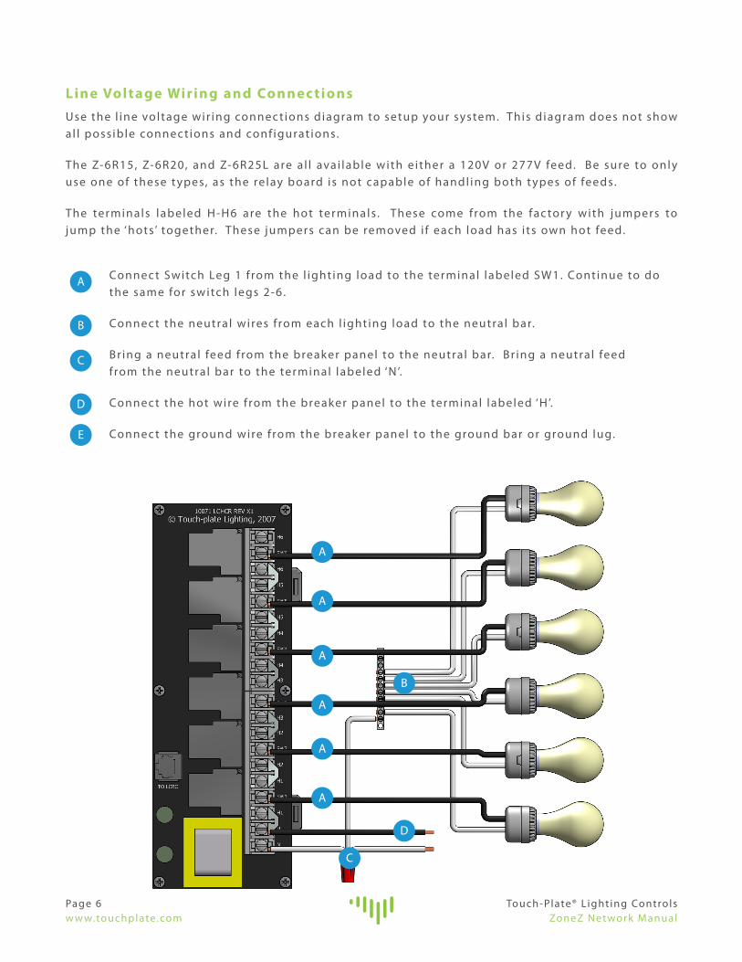
Line Voltage Wiring and Connec tionsUse the l ine voltage wir ing connec t ions diagram to setup your system. This d iagram does not show al l poss ible connec t ions and conf igurat ions.
The Z-6R15, Z-6R20, and Z-6R25L are a l l avai lable with e i ther a 120V or 277V feed. Be sure to only use one of these t ypes, as the re lay board is not capable of handl ing both t ypes of feeds.
The terminals labeled H-H6 are the hot terminals . These come from the fac tor y with jumpers to jump the ‘hots’ together. These jumpers can be removed i f each load has i ts own hot feed.
Connec t Switch Leg 1 f rom the l ight ing load to the terminal labeled SW1. Cont inue to do the same for switch legs 2-6 .
Connec t the neutra l wires f rom each l ight ing load to the neutra l bar.
Br ing a neutra l feed f rom the breaker panel to the neutra l bar. Br ing a neutra l feed f rom the neutra l bar to the terminal labeled ‘N’.
Connec t the hot wire f rom the breaker panel to the terminal labeled ‘H’.
Connec t the ground wire f rom the breaker panel to the ground bar or ground lug.
E
A
B
C
D
A
A
A
A
A
A
B
C
D
ALU D
ALU F
Touch-Plate® L ight ing ControlsZoneZ Net work Manual
Page 7w w w.touchplate.com
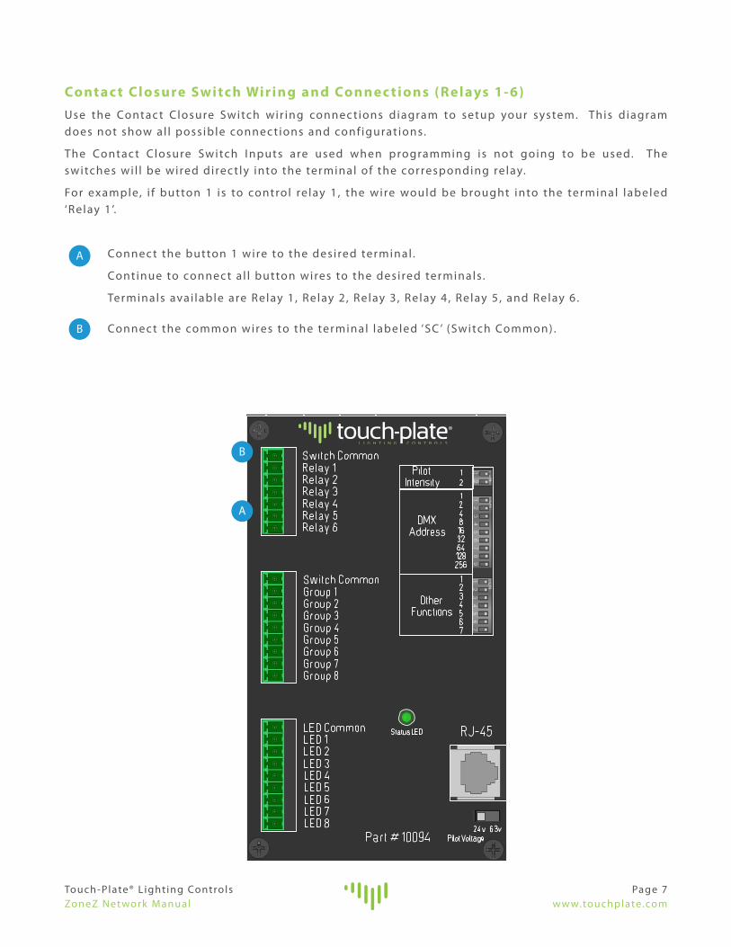
Contac t Closure Switch Wiring and Connec tions (Relays 1-6)Use the Contac t Closure Switch wir ing connec t ions diagram to setup your system. This d iagram does not show al l poss ible connec t ions and conf igurat ions.
The Contac t Closure Switch I nputs are used when programming is not going to be used. The switches wi l l be wired direc t ly into the terminal of the corresponding re lay.
For example, i f button 1 is to control re lay 1 , the wire would be brought into the terminal labeled ‘Relay 1 ’.
Connec t the button 1 wire to the desi red terminal .
Cont inue to connec t a l l button wires to the desi red terminals .
Terminals avai lable are Relay 1 , Relay 2 , Relay 3 , Relay 4 , Relay 5 , and Relay 6 .
Connec t the common wires to the terminal labeled ‘SC ’ (Switch Common) .
A
B
A
B
ALU D
ALU F
Page 8w w w.touchplate.com
Touch-Plate® L ight ing ControlsZoneZ Net work Manual
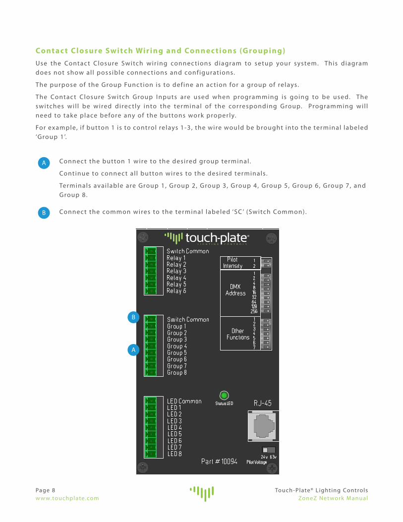
Contac t Closure Switch Wiring and Connec tions (G rouping)Use the Contac t Closure Switch wir ing connec t ions diagram to setup your system. This d iagram does not show al l poss ible connec t ions and conf igurat ions.
The purpose of the Group Func t ion is to def ine an ac t ion for a group of re lays.
The Contac t Closure Switch Group I nputs are used when programming is going to be used. The switches wi l l be wired direc t ly into the terminal of the corresponding Group. Programming wi l l need to take place before any of the buttons work proper ly.
For example, i f button 1 is to control re lays 1-3 , the wire would be brought into the terminal labeled ‘Group 1 ’.
Connec t the button 1 wire to the desi red group terminal .
Cont inue to connec t a l l button wires to the desi red terminals .
Terminals avai lable are Group 1 , Group 2 , Group 3 , Group 4 , Group 5 , Group 6 , Group 7 , and Group 8 .
Connec t the common wires to the terminal labeled ‘SC ’ (Switch Common) .
A
B
A
B

Touch-Plate® L ight ing ControlsZoneZ Net work Manual
Page 9w w w.touchplate.com
ALU D
ALU F
Contac t Closure Switch Wiring and Connec tions (LED)Use the Contac t Closure Switch wir ing connec t ions diagram to setup your system. This d iagram does not show al l poss ible connec t ions and conf igurat ions.
The LED outputs are used when LEDs are present on the Switches. These can be wired and used whether the Contac t Closure Switch I nputs or Group I nputs are used.
The LED outputs correspond to the LED locat ion on the switch.
For example, when wir ing LED #4 on the switch, br ing the LED wire to the terminal labeled ‘LED 4 ’.
Connec t the LED 1 wire to the desi red terminal .
Cont inue to connec t a l l LED wires to the desi red terminals .
Terminals avai lable are LED 1 , LED 2 , LED 3 , LED 4 , LED 5 , LED 6 , LED 7 , and LED 8 .
Connec t the common wires to the terminal labeled ‘PC ’ (Pi lot/LED Common) .
A
B
A
B

Page 10w w w.touchplate.com
Touch-Plate® L ight ing ControlsZoneZ Net work Manual
Time -Keep er Wiring and Connec tionsUse the Time -Keeper wir ing connec t ions diagram to setup your system. This d iagram does not show al l poss ible connec t ions and conf igurat ions.
The Time -Keeper wi l l be wired direc t ly into the terminal labeled ‘RS485’ on the ZNZ-ZN.
Connec t the Ground wire to the terminal labeled ‘S’ under the RS485 sec t ion.
Connec t the - wire to the terminal labeled ‘B ’ under the RS485 sec t ion.
Connec t the + wire to the terminal labeled ‘A’ under the RS485 sec t ion.
A
A

Touch-Plate® L ight ing ControlsZoneZ Net work Manual
Page 11w w w.touchplate.com
Time -Keep er NotesWhen a ZNZ-ZN is paired with a Time -Keeper, some of the sett ings change to ensure that they are compatible with one another. P lease review the fol lowing i f a Time -Keeper is par t of the system.
• A Time -Keeper paired with a ZNZ-ZN is only ut i l ized to program events.
• The ZNZ-ZN wi l l not a l low LEDs to reac t to events programmed through the Time -Keeper.
• The Address and Option DIP Switches are only ut i l ized i f a Time -Keeper is par t of the system. Pages 15 and 16 provide fur ther information on the DIP Switches.
Page 12w w w.touchplate.com
Touch-Plate® L ight ing ControlsZoneZ Net work Manual
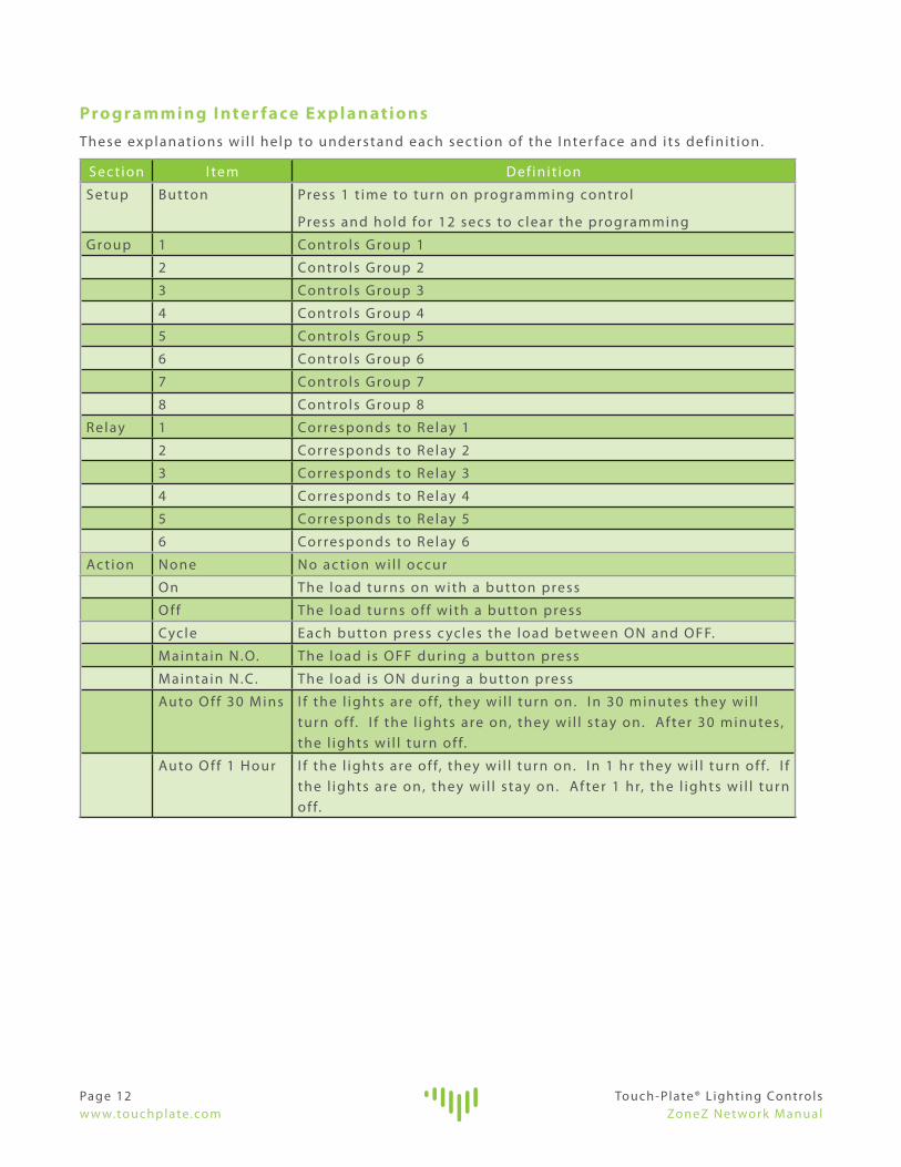
Pro gramming I nter face ExplanationsThese explanat ions wi l l help to understand each sec t ion of the I nter face and i ts def in i t ion.
Sec t ion I tem Definit ion
Setup Button Press 1 t ime to turn on programming control
Press and hold for 12 secs to c lear the programming
Group 1 Controls Group 1
2 Controls Group 2
3 Controls Group 3
4 Controls Group 4
5 Controls Group 5
6 Controls Group 6
7 Controls Group 7
8 Controls Group 8
Relay 1 Corresponds to Relay 1
2 Corresponds to Relay 2
3 Corresponds to Relay 3
4 Corresponds to Relay 4
5 Corresponds to Relay 5
6 Corresponds to Relay 6
Ac t ion None No ac t ion wi l l occur
On The load turns on with a button press
O ff The load turns of f with a button press
Cycle Each button press c ycles the load bet ween ON and OFF.
Maintain N.O. The load is OFF dur ing a button press
Maintain N.C. The load is ON dur ing a button press
Auto O ff 30 M ins I f the l ights are of f, they wi l l turn on. I n 30 minutes they wi l l turn of f. I f the l ights are on, they wi l l s tay on. Af ter 30 minutes, the l ights wi l l turn of f.
Auto O ff 1 Hour I f the l ights are of f, they wi l l turn on. I n 1 hr they wi l l turn of f. I f the l ights are on, they wi l l s tay on. Af ter 1 hr, the l ights wi l l turn of f.

Touch-Plate® L ight ing ControlsZoneZ Net work Manual
Page 13w w w.touchplate.com
Pro gramming G roup Func tionsUse the programming diagram to setup your system. Each load needs to have i ts Ac t ion determined before programming begins. Each system wi l l have di f ferent programming charac ter ist ics and this document does not show al l poss ible programming opt ions.
I f using M aintain options in a G roup and multiple inputs are pro grammed to control the same loads, the M aintain options c an make the other pro grammed Ac tions not work .
Press the ‘SE TUP ’ button once to begin the programming.
Press the ‘GROUP ’ button mult iple t imes unt i l the LED Is l i t nex t to the Group Number that i s to be programmed.
Press the ‘RELAY ’ button mult iple t imes unt i l the LED is l i t nex t to the Relay Number that i s to be programmed.
Press the ‘AC TION’ button mult iple t imes unt i l the LED Is l i t nex t to the Ac t ion that i s to be carr ied out by the re lay.
Press the ‘GROUP ’ button to move to the nex t group that i s des i red to be programmed.
B
A
B
C
D
A B C D

Page 14w w w.touchplate.com
Touch-Plate® L ight ing ControlsZoneZ Net work Manual
Pro gramming LED Func tionsUse the programming diagram to setup your system. These instruc t ions are used to program an LED to respond to the Group programming. Each system wi l l have di f ferent programming charac ter ist ics and this document does not show al l poss ible programming opt ions.
Press the ‘SE TUP ’ button t wice to begin the programming.
Press the ‘GROUP ’ button mult iple t imes unt i l the LED Is l i t nex t to the Group Number that i s to have a corresponding LED turned On.
Press the ‘GROUP ’ button to move to the nex t LED that i s des i red to be programmed.
A
B
C

Touch-Plate® L ight ing ControlsZoneZ Net work Manual
Page 15w w w.touchplate.com
Address D ip SwitchesThe Address Dip Switches are used to set the DMX Address only i f a Time -Keeper is present .
Normal ly, these Dip Switches come from the fac tor y pre -programmed. I f they do not , make sure you do not dupl icate addresses, as each ZNZ-ZN must have i ts own unique address.
Note that each ZNZ-ZN ut i l izes 6 addresses. For example, i f on one Time -Keeper net work there were t wo (2) ZNZ-ZN’s, the f i rst would be set to Address 73 and the second would be set to Address 79.
Do not change values unless direc ted by Touch-Plate! ! !
Val id addresses are f rom 73 to 193. Addresses are set us ing the nine Address Dip Switches, which each have a value noted in the char t below.
Address Dip Switch 1 2 3 4 5 6 7 8 9
Value 1 2 4 8 16 32 64 128 256
The values of a l l switches in the ON posit ion are added together and the total i s equal to the address. See the examples below :
DMX Address 1 : Turn on switch 1 only, and leave a l l other Address switches of f.
DMX Address 13: Turn on switches 1 , 3 and 4 . The values of those switches is 1 + 4 + 8 = 13.
Address 1 2 3 4 5 6 7 8 973 ON OFF OFF ON OFF OFF ON OFF OFF
79 ON ON ON ON OFF OFF ON OFF OFF
85 ON OFF ON OFF ON OFF ON OFF OFF
91 ON ON OFF ON ON OFF ON OFF OFF
97 ON OFF OFF OFF OFF ON ON OFF OFF
103 ON ON ON OFF OFF ON ON OFF OFF
109 ON OFF ON ON OFF ON ON OFF OFF
115 ON ON OFF OFF ON ON ON OFF OFF
121 ON OFF OFF ON ON ON ON OFF OFF
127 ON ON ON ON ON ON ON OFF OFF
133 ON OFF ON OFF OFF OFF OFF ON OFF
139 ON ON OFF ON OFF OFF OFF ON OFF
145 ON OFF OFF OFF ON OFF OFF ON OFF
151 ON ON ON OFF ON OFF OFF ON OFF
157 ON OFF ON ON ON OFF OFF ON OFF
163 ON ON OFF OFF OFF ON OFF ON OFF
169 ON OFF OFF ON OFF ON OFF ON OFF
175 ON ON ON ON OFF ON OFF ON OFF
181 ON OFF ON OFF ON ON OFF ON OFF
187 ON ON OFF ON ON ON OFF ON OFF
Val id Addresses are through Address 193

Page 16w w w.touchplate.com
Touch-Plate® L ight ing ControlsZoneZ Net work Manual
O ption D ip SwitchesThe Option Dip Switches are used to set d i f ferent func t ions.
Option ON/OFF Def init ion
1 ON DMX func t ional i t y i s ON. This has to be on when a Time -Keeper is a par t of the system.
1 OFF DMX func t ional i t y i s OFF.
2 ON N/A
2 OFF N/A
3 ON N/A
3 OFF N/A
4 ON N/A
4 OFF N/A
5 ON N/A
5 OFF N/A
6 ON N/A
6 OFF N/A
7 ON N/A
7 OFF N/A
Termination D ip SwitchesThe Terminat ion Dip Switches are used to set the Terminat ions.
Terminat ions Def init ion
A Pul l Up
B Pul l Down
AB Terminat ion
LED I ntensit y D ip SwitchesThe Pi lot I ntensit y Dip Switches are used to set the LED I ntensit y. This opt ion is only used when the fac tor y has been contac ted.
I ntensit y Def ini t ion
1 ON = Low I ntensit y
2 ON = Medium I ntensit y
1 & 2 ON = H igh I ntensit y

Touch-Plate® L ight ing ControlsZoneZ Net work Manual
Page 17w w w.touchplate.com
Troublesho oting G uideI f no response occurs when the system is powered up, use the fol lowing steps to ident i fy the problem.
1. Remove the Diecut f rom the ZNZ-ZN.
2 . Look for the LED indicator to be bl ink ing on the ZNZ-ZN.
a . For the indicator to be bl ink ing, power has to be correc t ly brought to the system.
b. I f the LED indicator i s not bl ink ing, conf i rm power connec t ions and then contac t the fac tor y for ass istance.
c. I f the LED indicator i s b l ink ing, move on to the nex t step.
3 . Ver i fy that the l ine voltage has been fed to a l l the necessar y re lays.
4 . Ver i fy that each l ight f ix ture is connec ted to the ‘Switched Leg’.
5 . Ver i fy that 120 VAC has been connec ted to the t ransformer on the Relay Board.
6 . Take a shor t p iece of thin wire (both ends need to be str ipped) and hold one end to the conduc t ive metal of the ‘Switch Common’.
7 . Take the other end of the shor t wire and tap i t to the conduc t ive metal of each of the Relay terminals , on the ZoneZ-N, one at a t ime.
a . Each touch should energize the re lay and change i ts state. The l ights in the respec t ive rooms should go ON and OFF when the terminal i s touched.
8 . I f the l ights do not respond, use a meter on the l ine voltage re lay outputs to see i f the voltage switches f rom 0 to 120 VAC.
9 . I f these steps do not solve the problem, please contac t the fac tor y for ass istance.

Page 18w w w.touchplate.com
Touch-Plate® L ight ing ControlsZoneZ Net work Manual
Frequently Asked Q uestions
1. What are Groups?
a. Groups a l low for a s ingle button to control mult iple re lays.b. For example: I n most bathrooms there are l ights above the s ink and above
the shower. I f both l ights are desi red to be turned on at the same t ime with the push of a s ingle button, Grouping makes this poss ible.
2 . What are the ‘Opt ion’ Func t ions?
a . Opt ion Func t ions are to be used when a Time -Keeper is connec ted to the ZNZ-ZN.
3 . What is the ‘DMX Address’?
a . The DMX Address is a number in a l ine of speci f ic addresses. b. This has to be done because ever ything has a unique address and has to be
programmed to do so.
4 . What is the ‘Pi lot Voltage’?
a . Pi lot Voltage is set to 24V f rom the fac tor y so i t can send the correc t voltage to the switches.
b. When us ing the Pi lot Voltage set at 6 .3V, th is can only be used when exist ing l i t switches are not updated at the same t ime.
5 . What are the ‘ Terminat ions’?
a . These are DMX l ine terminat ions. This i s only used i f a DMX control ler i s connec ted to the ZNZ-ZN.
6 . Why are there so many ‘HOTs’ and what are ‘Jumpers’?
a . The ‘HOTs’ are so power can be fed to a l l s ix re lays without us ing wire nuts. This wi l l help make the insta l lat ion as neat and order ly as poss ible.
b. The way that the power is fed to a l l s ix re lays is by us ing the ‘Jumpers’. These are metal inser ts that “ jump” the previous ‘HOT ’ to the nex t ‘HOT ’.
7 . How do you save the programming?
a. The programming is saved once the Group, Relay, or Ac t ion is entered and the button press is re leased.

Touch-Plate ZoneZ Net work ManualRevis ion: 1 .0a