Zone Inspection Criteria - dcfpnavymil.org · Zone Inspection Criteria . ... • For an outside...
46
Zone Inspection Criteria Here is a power point to help train Fire Marshals and Khaki inspectors What to look for and how to do a zone inspection (DCCM Terry Wylie)
-
Upload
truongdien -
Category
Documents
-
view
220 -
download
0
Transcript of Zone Inspection Criteria - dcfpnavymil.org · Zone Inspection Criteria . ... • For an outside...

Zone Inspection Criteria
Here is a power point to help train Fire Marshals and Khaki inspectors What to look for and how to do a zone inspection (DCCM Terry Wylie)

Bull’s Eye
Space “Length”
Compt. #
Division Respon
s.

Damage Control and System Marking Requirements
• Compartment bullseyes are to be applied in each space or compartment to identify the space, setting forth the frames which bound the space and the division responsible.
• A bullseye should be visible from each access to the space. • Lettering will be two inches in height applied over a 12-inch high by 15-inch wide
photoluminescent label or yellow painted area. • For photoluminescent adhesive material, use blue retro-reflective lettering, two
inches high; for painted bullseyes, use black lettering, two inches high. • Interior fire station bullseyes are to be applied as near as possible to each
interior fire plug, sized to best fit the area available, preferably immediately above the fire plug valve.
• The bullseye will identify the fire plug number and the valve number(s) necessary to isolate the fire plug in the event of damage.
• The photoluminescent painted area background is 12 inches high by 15 inches wide and has red painted lettering, two inches high.
• Photoluminescent adhesive material is 12 inches high by 15 inches wide with red retro-reflective lettering, two inches high.
• The red painted area background is 12 inches high by 15 inches wide with white lettering, two inches high.

Damage Control and System Marking Requirements
VALVE LABEL

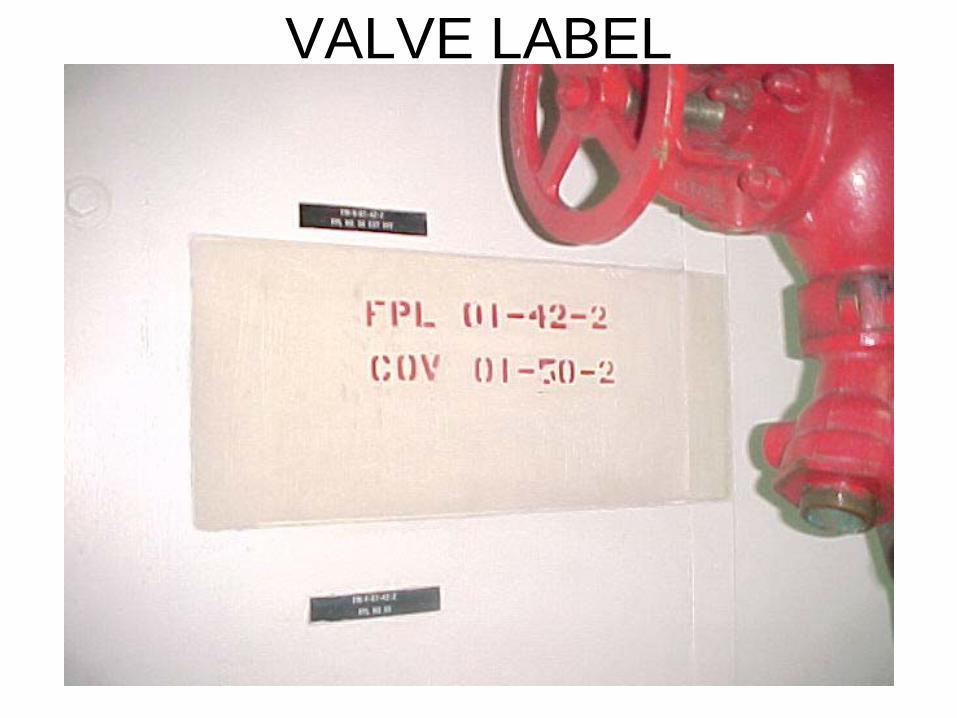
Compartment Check-Off Lists CCOL’s
Master- Maintained by DCA Individual- For Space w/ 1
Access Duplicate- For Space >1
Access Partial- For Small Space w/in
Larger Space

079-21.4.5.1 General. Compartment checkoff lists are prepared and supplied by the shipbuilder. Ship’s force is required to keep them current. CCOLs are prepared on form NAVSHIPS 9880/2 (REV 2-67) . Computer generated facsimiles may be used. Pen and ink changes are not authorized on computerized CCOLs. The DCA will maintain a master CCOL hard copy and a backup disk when the CCOL is computerized.
CCOL’s

079-21.4.5.1.2 The miscellaneous unclassified data fields category is deleted as a CCOL requirement since this data is also covered in DCAMS, EGLs and PMS.
CCOL’s
079-21.4.5.1.3 Any changes to the CCOLs will be as approved by the DCA. 079-21.4.5.1.4 Ensure that the division responsible or DC repair station is filled in on CCOL.

079-21.4.5.1.5 When using NAVSEA computerized software, the revision date and print date replace the signature requirement.
CCOL’s

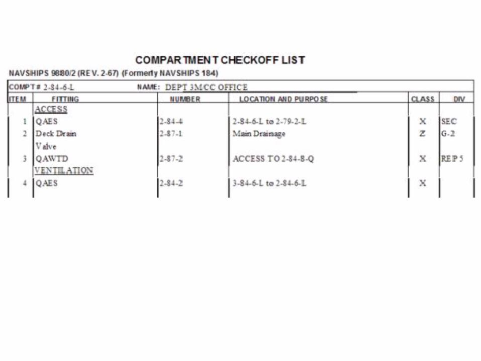
Mat’l Condition What’s Closed?
Zebra
Z Z Y Y X X
Yoke Y Y X X
X-ray X X
D Z

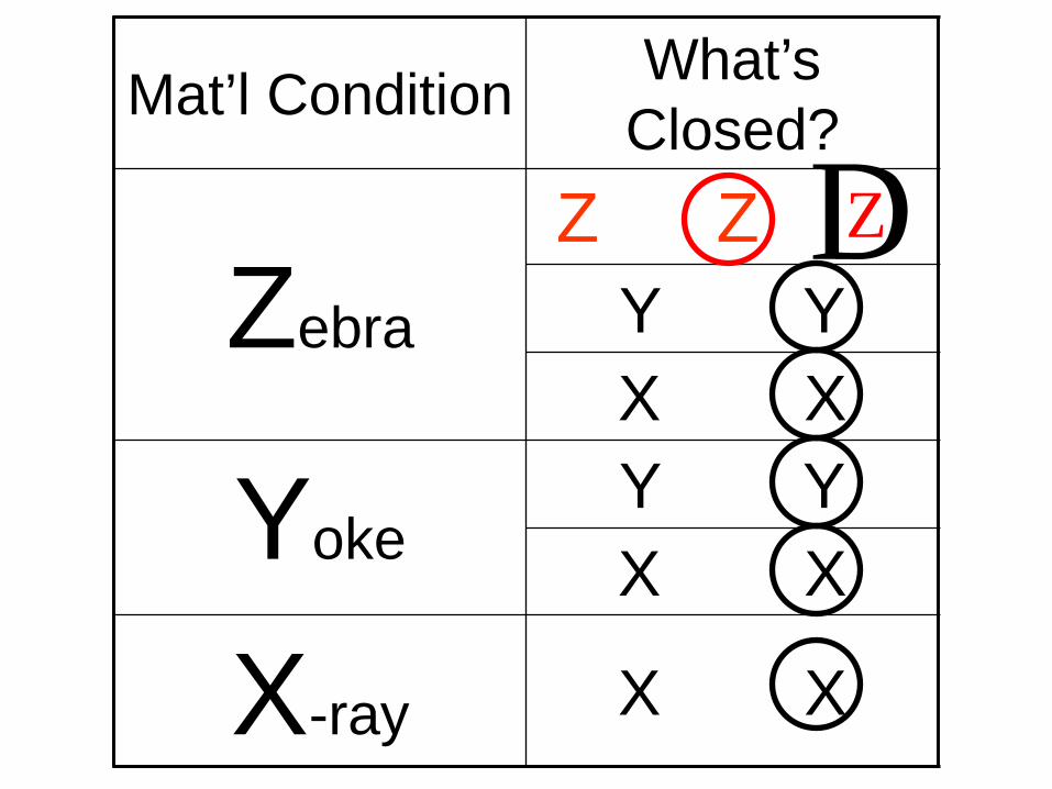
Material Condition
Must be photo engraved Or 3M sticker Can not be more than 50% worn
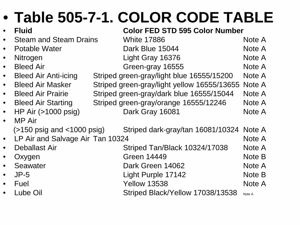
• Table 505-7-1. COLOR CODE TABLE • Fluid Color FED STD 595 Color Number
• Steam and Steam Drains White 17886 Note A • Potable Water Dark Blue 15044 Note A • Nitrogen Light Gray 16376 Note A • Bleed Air Green-gray 16555 Note A • Bleed Air Anti-icing Striped green-gray/light blue 16555/15200 Note A • Bleed Air Masker Striped green-gray/light yellow 16555/13655 Note A • Bleed Air Prairie Striped green-gray/dark blue 16555/15044 Note A • Bleed Air Starting Striped green-gray/orange 16555/12246 Note A • HP Air (>1000 psig) Dark Gray 16081 Note A • MP Air (>150 psig and <1000 psig) Striped dark-gray/tan 16081/10324 Note A • LP Air and Salvage Air Tan 10324 Note A • Deballast Air Striped Tan/Black 10324/17038 Note A • Oxygen Green 14449 Note B • Seawater Dark Green 14062 Note A • JP-5 Light Purple 17142 Note B • Fuel Yellow 13538 Note A • Lube Oil Striped Black/Yellow 17038/13538 Note A

Foam Discharge Plugs (AFFF) Striped Red/Green 11105/14062 Note A Gasoline Yellow 13538 Note B Fresh water Light Blue 15200 Note A Hydraulic Orange 12246 Note A Refrigerant Dark Purple 17100 Note B Hydrogen Chartreuse 23814 Note A Amine Dry Cleaning Fluid Brown 10080 Note B Helium Buff 10371 Note A Helium/Oxygen Striped Buff/Green 10371/14449 Note A Sewage Gold 17043 Note A Halon Striped Gray/White 16187/17886 Note A Fire Main Red 11105 Note C Chilled Water Striped Light Blue/Dark Green 15200/14062 Note A Demin. Elect. Cooling Water Striped Light Blue/ Dark Purple 15200/17100 Note A AFFF Concentrate Striped Light Blue/Red 15200/11105 Note A Oil Pollution Abatement Black 17038 Note B,E Jacket Water/Waste Heat Striped Light Blue/Black 15200/17038 Note A Divers life support system Various/Various Note F AFFF Solution Striped Red/Dark Green 11105/14062 Note D
•Table 505-7-1. COLOR CODE TABLE
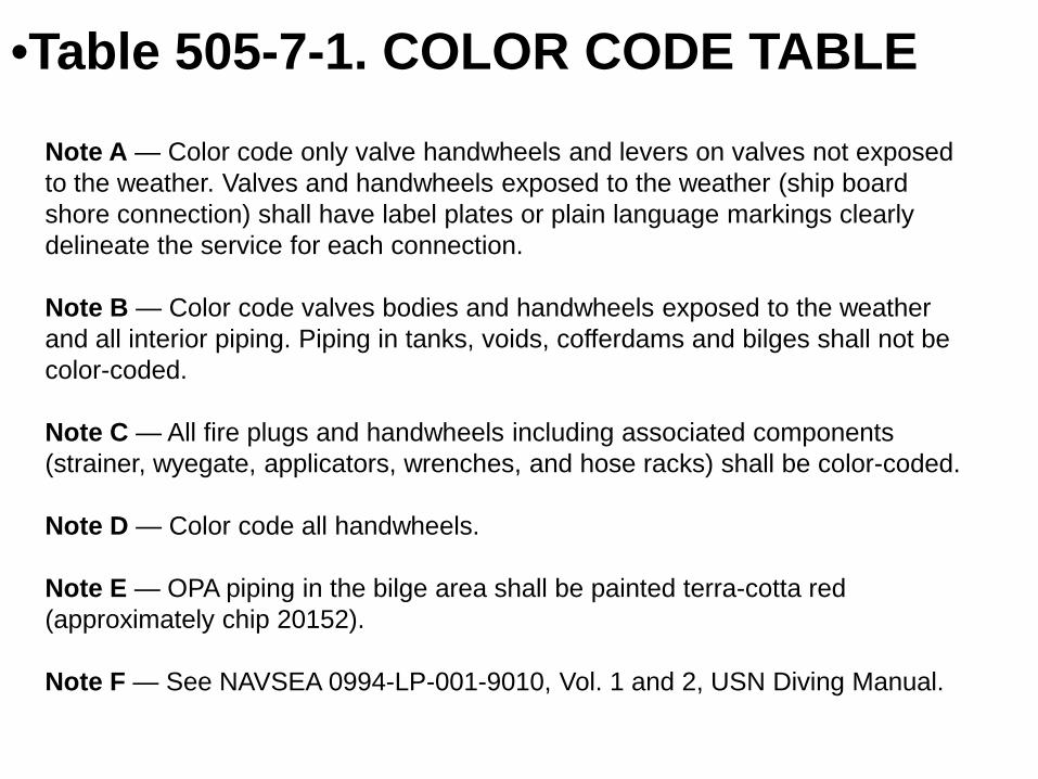
Note A — Color code only valve handwheels and levers on valves not exposed to the weather. Valves and handwheels exposed to the weather (ship board shore connection) shall have label plates or plain language markings clearly delineate the service for each connection. Note B — Color code valves bodies and handwheels exposed to the weather and all interior piping. Piping in tanks, voids, cofferdams and bilges shall not be color-coded. Note C — All fire plugs and handwheels including associated components (strainer, wyegate, applicators, wrenches, and hose racks) shall be color-coded. Note D — Color code all handwheels. Note E — OPA piping in the bilge area shall be painted terra-cotta red (approximately chip 20152). Note F — See NAVSEA 0994-LP-001-9010, Vol. 1 and 2, USN Diving Manual.
•Table 505-7-1. COLOR CODE TABLE

• 505-7.8.3.1.3 Markings shall be spaced not more than 15 feet apart, as measured along the run of piping, and shall be applied in conspicuous locations, preferably near control valves. Where piping is concealed behind sheeting, the markings shall be spaced not more than 5 feet apart, measured along the run of piping.

• For an outside diameter of 6 inches and larger (bare or lagged) pipe, apply markings that have 2-inch high letters. On pipes or lagging with a diameter between 2 inches and less than 6 inches, apply markings that have 1-inch high letters. For diameters less than 2 inches, use 3/8-inch high letters. The marking may be stenciled or applied using preprinted retro-reflective labels. Directionof- flow arrows shall also be marked on the piping. As a minimum, one arrow must be placed immediately following the functional name. Additional arrows shall be placed at junctions and tees to indicate flow divisions. Flow arrows may be stenciled or applied using preprinted retro-reflective labels.
505-7.8.3.1 Pipe Marking.

Fan Room Storage
NSTM 510-7.2.1 {paraphrased} Fan rooms must not be used for stowage or office space. Swabs, deck gear, or trash shall not be stowed in fan rooms or HVAC terminals shall not be used for the stowage of clothing, shoes, toilet articles, or any other items.
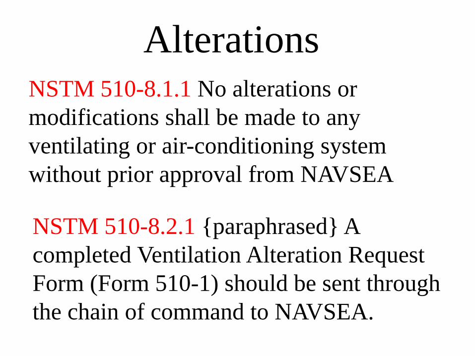
Alterations NSTM 510-8.1.1 No alterations or modifications shall be made to any ventilating or air-conditioning system without prior approval from NAVSEA
NSTM 510-8.2.1 {paraphrased} A completed Ventilation Alteration Request Form (Form 510-1) should be sent through the chain of command to NAVSEA.

VALVE INSPECTION • LEAKAGE • VERDIGRIS • LUBRICATION • HANDWHEEL FIRMLY ATTACHED • VALVE IDENTIFICATION • BRIDGEWALL MARKING/ FLOW
ARROW • FLANGE SHIELD INSTALLED
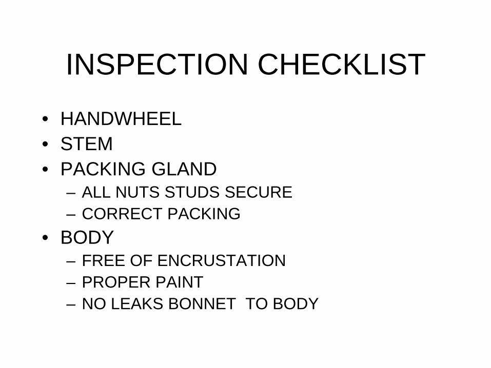
• HANDWHEEL • STEM • PACKING GLAND
– ALL NUTS STUDS SECURE – CORRECT PACKING
• BODY – FREE OF ENCRUSTATION – PROPER PAINT – NO LEAKS BONNET TO BODY
INSPECTION CHECKLIST

Firestations
Challenges • Hydrostatic test reference mark not visible or separation between mark and coupling evident. • Hose hydrostatic test date not properly marked or outside of periodicity (36 months). • Vari-nozzle seized or difficult to operate. • Missing spanner wrenches. • Ferrous fasteners.

Portable Extinguishers
• Mounting brackets in poor condition (no longer meet Grade A shock condition)
• Safety pins, tamper seals missing. • Fittings (hose, horn, cap) overtight / loose. • Agent not in proper condition or amount.
– PKP hard packed, too little, too much. – AFFF/CO2 pressure out of spec.
• PMS tags filled out incorrectly. • Cylinder overdue for hydrostatic testing. • Stowage location markings (photolum).

Portable DC Extinguishers
Challenges • PKP – Dry Chemical Extinguisher.
– Mounting brackets in poor physical condition (no longer in Grade A shock condition per GSO).
– Valve safety pin missing. – Fill cap overtight (should be hand tight). – PKP powder hard packed. – PKP fill height is not within standards:
• 3 to 5 inches for ANSUL and 5 to 8 inches for FLAG extinguishers as measured from the lowest thread in the fill opening to the upper surface of the PKP powder.
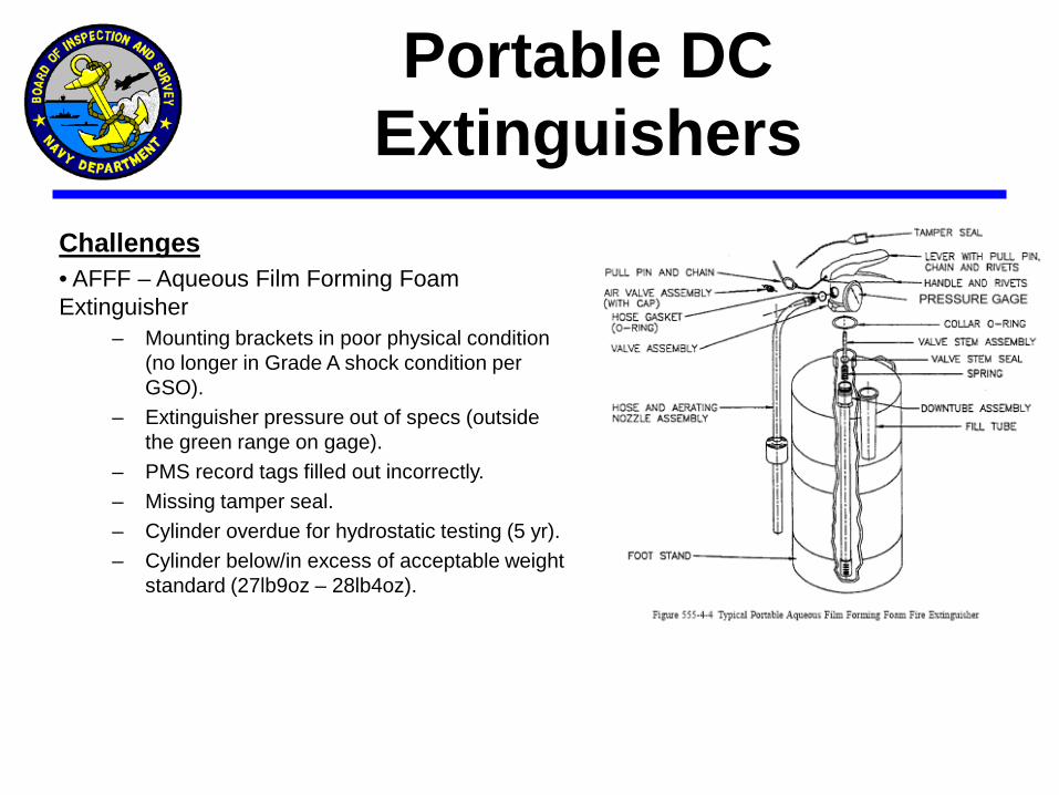
Challenges • AFFF – Aqueous Film Forming Foam Extinguisher
– Mounting brackets in poor physical condition (no longer in Grade A shock condition per GSO).
– Extinguisher pressure out of specs (outside the green range on gage).
– PMS record tags filled out incorrectly. – Missing tamper seal. – Cylinder overdue for hydrostatic testing (5 yr). – Cylinder below/in excess of acceptable weight
standard (27lb9oz – 28lb4oz).
Portable DC Extinguishers

Portable DC Extinguishers
Challenges •CO2 – Portable 15lb CO2 Extinguisher
– Mounting brackets in poor physical condition (no longer in Grade A shock condition per GSO).
– PMS record tags filled out improperly. – Cylinder past due for hydrostatic testing
(12yr). – Valve safety pins missing. – Stowage location not properly marked
with photoluminescent labels. – Exposed hose to horn metallic coupling
not covered with electrical tape. – Cylinder weight was not within PMS
standards.
Damage Control and System Marking Requirements
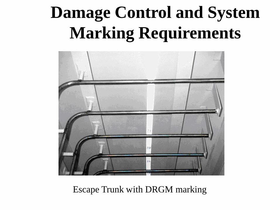
Escape Trunk with DRGM marking

Damage Control and System Marking Requirements
• Frame markings are to be applied every 14 feet or once centered in a given compartment that is less than 14 feet fore to aft.
• APC system markings are installed as near as practicable to actuators. • The markings for portable and installed firefighting systems and
extinguishers are to be located as near as practical, immediately above the extinguisher, hose reel or actuator.
• Vertical or horizontal markings for the OBA, SCBA and EEBD storage
cabinets and OBA canister stowage cabinets are to be provided. • EXIT signs with arrows are to be located within 5 feet of each access
(door, hatch) to a compartment, except where the access opens directly to weather. The arrow direction is to indicate nearest egress route to weather area (i.e., main deck, hangar, flight deck).

Damage Control and System Marking Requirements
Damage Control and System Marking Requirements
• Each door passed through along egress routes will be marked by photoluminescent strips around the outside perimeter to illuminate the opening.
• The word EXIT is to be placed on each door in a normal egress route, six inches above the bottom of the door.
• Balanced doors serving machinery spaces shall have an EXIT marker applied in the center of the door only.
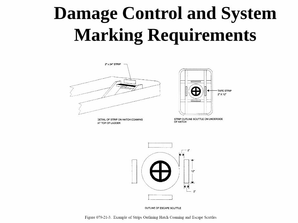
• The side of a hatch coaming where the ladder attaches will be marked with a photoluminescent strip to indicate the location of the coamings.
• Entrance doors to damage control spaces shall be painted red. Retro-reflective signs shall be used to identify the space and the numbers shall be placed below the letters.
• Inclined ladders are to be marked by applying photoluminescent strips on the inner frame, alternating sides with each step. The handrails will be marked with six bands wrapped on each side.

FRAME LABEL
A Frame Label shall be Installed in Compartments over
14 feet Long, every 14 feet.

2. Retroreflective Diamond Grade

Damage Control and System Marking Requirements
Damage Control and System Marking Requirements

Damage Control and System Marking Requirements

COMPARTMENT ID PLATE
Door # Leads to this Compt.

Ship's Complement
Embarked Personnel
150% 100%
EEBD ALLOWANCES
Berthing Spaces 100% (One EEBD per Rack)
OCENCO 15 years

Engineering Spaces 200%
EEBD ALLOWANCES (cont’d)
(Two EEBDs per GQ Watchstander)
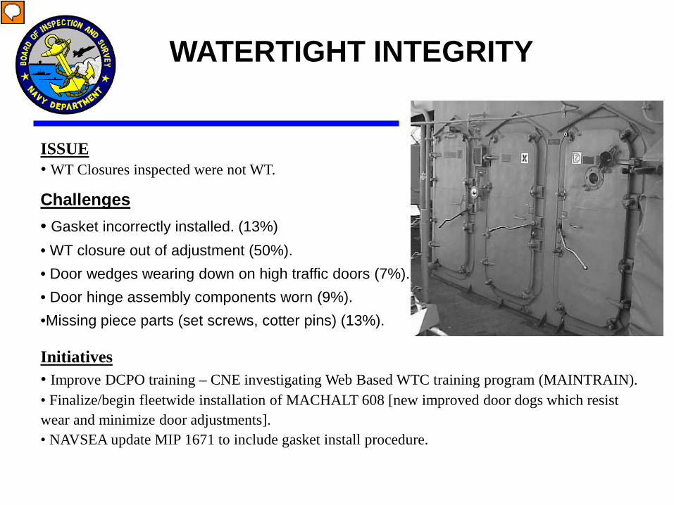
ISSUE • WT Closures inspected were not WT.
Challenges • Gasket incorrectly installed. (13%) • WT closure out of adjustment (50%). • Door wedges wearing down on high traffic doors (7%). • Door hinge assembly components worn (9%). •Missing piece parts (set screws, cotter pins) (13%). Initiatives • Improve DCPO training – CNE investigating Web Based WTC training program (MAINTRAIN). • Finalize/begin fleetwide installation of MACHALT 608 [new improved door dogs which resist wear and minimize door adjustments]. • NAVSEA update MIP 1671 to include gasket install procedure.
WATERTIGHT INTEGRITY
Presenter
Presentation Notes
Discuss “In Harm’s Way Analogy Low-tech but High maintenance

General guidance for inspections
Doors, hatches and scuttles should routinely be inspected by DCPOs, work center supervisors and zone inspectors for: Loose, missing and damaged parts Paint, rust or other foreign matter on gaskets, knife edges and
working parts. Binding and difficult operations Distortion and deterioration of metal surfaces Hinge pin wear and pins that are not properly secured. Gasket cracks, deterioration, hardness, permanent set over 1/8 inch
deep and gaps where the gasket ends meet. No more than one joints in gaskets. Gaskets must be no less than 24 inches in length.
Lesson Topic 1.4, Watertight Closures Inspection and Maintenance
General guidance for inspections
Doors, hatches and scuttles should routinely be inspected by DCPOs, work center supervisors and zone inspectors for: Obstructed access to escape scuttles. Packing plungers intact and stick packing adequate (except on
closures with self-lubricated bushings) Broken or missing spring clips. Missing special purpose wrenches:
dogging wrenches T-wrenches engineer's wrench (1-5/16 inch)
Lesson Topic 1.4, Watertight Closures Inspection and Maintenance

Watertight Door Maintenance
The maximum acceptable variation for knife edge straightness is plus or minus 1/8 inch.
The maximum acceptable warpage of the door frame is 1/8 inch.
If frame/coaming warpage is excessive, or the knife edge straightness is not within tolerance, initiate replace the closure.
Lesson Topic 1.4, Watertight Closures Inspection and Maintenance
Watertight Door Maintenance
Inspect the knife edge for paint, dirt, rust or nicks.
Be sure to remove the abrasive grit with a clean rag to prevent the grit from getting embedded in the gasket.
Lesson Topic 1.4, Watertight Closures Inspection and Maintenance
NOTE: For steel knife edges, remove paint and rust with #320 grit aluminum oxide abrasive cloth.
CAUTION: For aluminum knife edges, remove paint with a nylon scrubbing pad and rag only.

Watertight Door Maintenance
Inspect hinge sleeves and hinge pins for wear
With the door opened, grasp the door from the hand lever side and push it towards the hinged side. The door should not give more than approximately 3/16 inch.
If it does, either the hinge pins and/or washers are worn, or
the holes for the hinge pins have become enlarged.
Lesson Topic 1.4, Watertight Closures Inspection and Maintenance
NOTE: Do not confuse hinge pin wear with normal play in the hinge blades.

Watertight Door Maintenance
Another indication of hinge pin wear is if the metal channel surrounding the gasket on the door side is rubbing against the knife edge, or if the door panel rubs one or more side dogs when opening and closing.
Lesson Topic 1.4, Watertight Closures Inspection and Maintenance