
Zonal modeling of radiative heat transfer in industrial furnaces using simplified model for exchange...
12
Zonal modeling of radiative heat transfer in industrial furnaces using simplified model for exchange area calculation Hadi Ebrahimi a , Akbar Zamaniyan a,⇑ , Jafar S. Soltan Mohammadzadeh b , Ali Asghar Khalili c a Department of Natural Gas Conversion, Gas Research Division, Research Institute of Petroleum Industry (RIPI), Tehran 14665-137, Iran b Department of Chemical Engineering, University of Saskatchewan, College of Engineering, 57 Campus Drive, Saskatoon SK, Canada S7N 5A9 c Chemistry and Chemical Engineering Division, Research Institute of Petroleum Industry (RIPI), Tehran 14665-137, Iran article info Article history: Received 19 July 2012 Received in revised form 6 January 2013 Accepted 20 February 2013 Available online xxxx Keywords: Radiation heat transfer Zone method Exchange area Mathematical modeling Furnace abstract The zonal analysis of industrial furnaces is considered with three-dimensional radiative heat transfer, incorporated with the mathematical zone method. In this method exchange areas are determined by simplified numerical integration in three dimensions for surface- surface, surface-gas and gas–gas zones for absorbing and emitting media. By focusing on new strategies to overcome the drawbacks of evaluating direct exchange areas, it is shown that the zone method is an effective numerical method for modeling three-dimensional thermal performance of gas-filled enclosures. Also the developed method for evaluating of exchange area is presented and compared with other methods in both sides of CPU time and accuracy. The method can decrease about 70% in error of calculation of some exchange areas as compared with the other numerical methods. Ó 2013 Elsevier Inc. All rights reserved. 1. Introduction Thermal radiation is a dominant heat transfer mode in furnaces as compared with convection and conduction transfers. Generally radiative transfer is provided by the combustion of the fuels in a burner. This kind of heat transfer depends strongly on the system geometry, the nature of surface and gas zones, and the relative positions of sinks and sources in the system. Many reports are found in the literature representing the attempts to model and analysis of the radiative envi- ronments [1–6]. Numerical solutions of conservation equations for radiative transfer, including integro-differential forms, are possible now using high-speed computer processors. So, not only other modes of heat transfer but also turbulent phenomena could be coupled with these equations to understand the process behavior of the fluid flows by finding key parameters such as temperature. However, long computation time of solving the equations, even with most powerful and high-speed modern computers is still an important challenge. The integro-differential equations for radiative heat transfer have been solved by the methods such as spherical harmonics and discrete ordinates [1]. The method of spherical harmonics or P N approxi- mation was first proposed by Jeans [3] on the radiative transfer in stars. This method converts the transfer equations into a set of simultaneous partial differential equations. The discrete ordinates (S N approximation) method was introduced by Chandrasekhar [5] on stellar and atmospheric radiation. This method is based on a discrete representation of directional var- iation of radiative intensity. The integro-differential techniques for radiative transfer are easy to solve for simple geometry problems but these methods are complex and difficult when radiative properties vary with direction or in presence of con- siderable scattering and for complex geometries. 0307-904X/$ - see front matter Ó 2013 Elsevier Inc. All rights reserved. http://dx.doi.org/10.1016/j.apm.2013.02.053 ⇑ Corresponding author. Tel.: +98 (21) 48252336; fax: +98 (21) 44739716. E-mail address: [email protected] (A. Zamaniyan). Applied Mathematical Modelling xxx (2013) xxx–xxx Contents lists available at SciVerse ScienceDirect Applied Mathematical Modelling journal homepage: www.elsevier.com/locate/apm Please cite this article in press as: H. Ebrahimi et al., Zonal modeling of radiative heat transfer in industrial furnaces using simplified model for exchange area calculation, Appl. Math. Modell. (2013), http://dx.doi.org/10.1016/j.apm.2013.02.053
-
Upload
ali-asghar -
Category
Documents
-
view
217 -
download
5
Transcript of Zonal modeling of radiative heat transfer in industrial furnaces using simplified model for exchange...

Applied Mathematical Modelling xxx (2013) xxx–xxx
Contents lists available at SciVerse ScienceDirect
Applied Mathematical Modelling
journal homepage: www.elsevier .com/locate /apm
Zonal modeling of radiative heat transfer in industrial furnacesusing simplified model for exchange area calculation
0307-904X/$ - see front matter � 2013 Elsevier Inc. All rights reserved.http://dx.doi.org/10.1016/j.apm.2013.02.053
⇑ Corresponding author. Tel.: +98 (21) 48252336; fax: +98 (21) 44739716.E-mail address: [email protected] (A. Zamaniyan).
Please cite this article in press as: H. Ebrahimi et al., Zonal modeling of radiative heat transfer in industrial furnaces using simplifiedfor exchange area calculation, Appl. Math. Modell. (2013), http://dx.doi.org/10.1016/j.apm.2013.02.053
Hadi Ebrahimi a, Akbar Zamaniyan a,⇑, Jafar S. Soltan Mohammadzadeh b, Ali Asghar Khalili c
a Department of Natural Gas Conversion, Gas Research Division, Research Institute of Petroleum Industry (RIPI), Tehran 14665-137, Iranb Department of Chemical Engineering, University of Saskatchewan, College of Engineering, 57 Campus Drive, Saskatoon SK, Canada S7N 5A9c Chemistry and Chemical Engineering Division, Research Institute of Petroleum Industry (RIPI), Tehran 14665-137, Iran
a r t i c l e i n f o
Article history:Received 19 July 2012Received in revised form 6 January 2013Accepted 20 February 2013Available online xxxx
Keywords:Radiation heat transferZone methodExchange areaMathematical modelingFurnace
a b s t r a c t
The zonal analysis of industrial furnaces is considered with three-dimensional radiativeheat transfer, incorporated with the mathematical zone method. In this method exchangeareas are determined by simplified numerical integration in three dimensions for surface-surface, surface-gas and gas–gas zones for absorbing and emitting media. By focusing onnew strategies to overcome the drawbacks of evaluating direct exchange areas, it is shownthat the zone method is an effective numerical method for modeling three-dimensionalthermal performance of gas-filled enclosures. Also the developed method for evaluatingof exchange area is presented and compared with other methods in both sides of CPU timeand accuracy. The method can decrease about 70% in error of calculation of some exchangeareas as compared with the other numerical methods.
� 2013 Elsevier Inc. All rights reserved.
1. Introduction
Thermal radiation is a dominant heat transfer mode in furnaces as compared with convection and conduction transfers.Generally radiative transfer is provided by the combustion of the fuels in a burner. This kind of heat transfer dependsstrongly on the system geometry, the nature of surface and gas zones, and the relative positions of sinks and sources inthe system. Many reports are found in the literature representing the attempts to model and analysis of the radiative envi-ronments [1–6].
Numerical solutions of conservation equations for radiative transfer, including integro-differential forms, are possiblenow using high-speed computer processors. So, not only other modes of heat transfer but also turbulent phenomena couldbe coupled with these equations to understand the process behavior of the fluid flows by finding key parameters such astemperature. However, long computation time of solving the equations, even with most powerful and high-speed moderncomputers is still an important challenge. The integro-differential equations for radiative heat transfer have been solvedby the methods such as spherical harmonics and discrete ordinates [1]. The method of spherical harmonics or PN approxi-mation was first proposed by Jeans [3] on the radiative transfer in stars. This method converts the transfer equations into aset of simultaneous partial differential equations. The discrete ordinates (SN approximation) method was introduced byChandrasekhar [5] on stellar and atmospheric radiation. This method is based on a discrete representation of directional var-iation of radiative intensity. The integro-differential techniques for radiative transfer are easy to solve for simple geometryproblems but these methods are complex and difficult when radiative properties vary with direction or in presence of con-siderable scattering and for complex geometries.
model

Nomenclature
A area of surface zones (m2)dx, dy, dz dimensions of a sub-zone in x, y, and z directions (m)Eg, Es black emissive powers for gases and surfaces (Wm�2)gigj; GiGj direct and total exchange areas for volumes i and j (m2)gisj; GiSj direct and total exchange areas for volume i and surface j (m2)Ng, N0g number of volume zones
Ns;N0s number of surface zones
Q heat (W)r distance between centers of two zones of i and jr0 distance between centers of two sub-zones of m and nsisj; SiSj direct and total exchange areas for surfaces i and j (m2)SM a matrixT temperature (K)TM a matrixV volume of volume zones (m3)x, y, z Cartesian coordinatesXM a matrix
Greek lettersb extinction coefficientdij Kronecker deltae emissivityq reflectivity, in the present study, it is equal to emissivity, eh angle between r direction and normal to surface
Subscriptsg, v gas or volume zonei, j index for two zoness surface zone
2 H. Ebrahimi et al. / Applied Mathematical Modelling xxx (2013) xxx–xxx
Hottel and Cohen [6] developed zone method for absorbing and emitting media. They evaluated the important parame-ters of radiative enclosure, exchange areas, based on graphical methods to import them to the energy balance of the system.However, graphical choice of evaluation is not useful in complex geometries and computer simulations. Hottel and Sarofim[7] presented some tables and graphs in their well-known book. The method has been used for many applications in Carte-sian or cylindrical coordinate systems [1].
The Monte-Carlo statistical method was first applied to thermal radiation problems by Fleck [8] and Howell and Perlmut-ter [9]. This method used the random numbers and probability distribution functions for calculating the exchange factorsand it could be coupled with zone method. In practice, complex radiant enclosure problems are often best treated by calcu-lating exchange factors through Monte Carlo simulation. However due to inherent statistical nature, these estimations con-tain random errors that cause violations of the reciprocity rule of the exchange factors, and consequently the second law ofthermodynamics [10].
There have been several attempts to evaluate the integral forms of direct exchange areas (DEAs). A simple procedure isreducing of integral order that has already considered by several authors that studied the multifold integrals in special cases[10–14]. A simplified technique for evaluating surface-volume exchange areas was shown by Becker [13]. He proposed asolution for a gray-gas-to-surface area for a rectangular parallelepiped gas volume and an adjacent face, in terms of elemen-tary functions and single integrals. Moreover, Tucker [14] presented more accurate data covering a range of optical thick-nesses from zero to 18 and simple exponential correlations which could easily be implemented into a computer program.
Sika [15] reduced analytically multiple integral of direct exchange areas bringing in a significant increase in computingefficiency. Tian and Chiu [16] reduced the integration order by a variable transformation. They also proposed that the meth-od may be refined in regions consisting of large temperature gradient with a proper accuracy. They later [17] used the FiniteVolume Method (FVM) for direct exchange areas of adjacent and overlapping zones; whereas, they employed a more efficientmidpoint integration scheme for the majority of nonadjacent zones, where the integrands are smooth. They applied themethod for an infinitely long black-walled rectangular enclosure and proved their method.
Increasing the number of zones allows the use of a simple efficient technique for evaluation of direct exchange areas.Modest [18] found that for sufficiently large number of zones, all exchange areas except one may be calculated by evaluatingthe integral between zone centers, multiplied by the applicable zone areas and/or volumes [1]. He demonstrated that errorsassociated with the closest zones would be reduced by applying conservation of energy.
Please cite this article in press as: H. Ebrahimi et al., Zonal modeling of radiative heat transfer in industrial furnaces using simplified modelfor exchange area calculation, Appl. Math. Modell. (2013), http://dx.doi.org/10.1016/j.apm.2013.02.053

H. Ebrahimi et al. / Applied Mathematical Modelling xxx (2013) xxx–xxx 3
In the present work the zonal mathematical model of radiative transfer has been adapted to predict the performance ofindustrial furnaces with emphasis on the use of three-dimensional zone method that deals with comprehensive studies inradiative transfer for the furnaces, boilers, and other fired heaters [10,19].
Because of difficulties in evaluating direct-exchange areas (DEA) [6,7,11] and solving the matrices caused by calculation oftotal exchange areas [20,21], the zone method has not been widely used for radiative heat transfer modeling particularly inthree dimensions. Moreover, difficulty of using the zone method for complex geometries, errors encountered from four to sixfold integrals particularly self-zone radiation mode, and high amount of CPU time are other reasons that researchers do notprefer to use the method. They usually use spherical harmonics (PN approximation) and discrete ordinates [3,5,22]. However,in the present study the authors have focused on the drawbacks of the method particularly high computation time and theproblem of center-to-center zones (since a gas zone could exchange radiative heat by itself or any adjacent surfaces). In thismethod exchange areas are determined by simplified numerical integration in three dimensions for all surface-surface, sur-face-gas and gas–gas zones for absorbing and emitting media. In the current study, new strategies are applied to overcomethe drawbacks of evaluating direct exchange areas. It is shown that the zone method is an effective numerical method formodeling of three-dimensional thermal performance of gas-filled enclosures. To circumvent the problem a simplified meth-od of calculating direct exchange areas is considered and the performance of the algorithm regarding CPU time and accuracyis studied.
The current zonal radiative model deals with choosing a sufficient number of zones such a way that after normalization ofdirect exchange areas and total exchange areas, errors are negligible in the radiative transfer calculations. The direct ex-change areas are calculated based on the center-to-center orientation and distance concept. For more remote zone pairs, di-rect calculation is based on the spacing and orientation of the centers of each element. Since the exchange areas betweenother elements are small enough, the common integral-based evaluation or center-to-center distance method could be usedwithout contributing significant errors [10].
Using the current three-dimensional zone method, a working model is developed and the model performance is validatedusing the results of previous work in the literature. It is shown that not only the model could predict the direct exchange areaperfectly in comparison to the well-performed graphical method [7], but it could also be used in the absorbing and emittingmedia enclosures. For this goal, the results of an idealized furnace were compared with those of previous work. Moreover,the effect of flame position on the ideal-radiative furnace performance is investigated as a case study. As an another verifi-cation, this furnace with four flame zones as the source together with the bottom sink-surface of the gas enclosure was sim-ulated by using P1-approximation model of radiation.
2. Modeling
2.1. Zonal analysis
The zone method can be used for modeling of radiative heat transfer in an absorbing, emitting and scattering medium. Inthis method the enclosure is subdivided into a finite number of isothermal volumes and surface area zones [7]. Energy bal-ance and other governing equations are then applied to the radiative exchange between any two zones [7,12], employingpre-calculated ‘‘exchange areas’’ [1]. In fact, the exchange areas (direct and total) are more general forms of well-known viewfactors. Finally a set of simultaneous nonlinear equations are solved numerically to find unknown parameters e.g. temper-atures and heat fluxes.
2.2. Direct exchange areas
A direct exchange area, between two zone elements i and j, is defined by the total directly exchanged flux without reflec-tions and scattering. Three types of direct exchange areas (DEAs), for surface-surface (sisj), surface-volume (sigj), and volume-volume (gigj) zones, are given as follow [1]:
Pleasefor ex
sisj ¼Z
Ai
ZAj
e�br cos hi cos hj
pr2 dAidAj ð1Þ
sigj ¼Z
Ai
ZVj
e�brbjcos hi
pr2 dAidVj ð2Þ
gigj ¼Z
Vi
ZVj
e�brbibj1
pr2 dVidVj ð3Þ
where:
b ¼ 1r
Z rj
ri
brdr ð4Þ
cite this article in press as: H. Ebrahimi et al., Zonal modeling of radiative heat transfer in industrial furnaces using simplified modelchange area calculation, Appl. Math. Modell. (2013), http://dx.doi.org/10.1016/j.apm.2013.02.053

4 H. Ebrahimi et al. / Applied Mathematical Modelling xxx (2013) xxx–xxx
br, the extinction coefficient between two zones of i and j may be varied along r direction that depends on the gas zone prop-erties. Each surface zone with surface area of A has an angle between surface and normal vector, h. For these two surfacezones, DEA is calculated through the distance r where there are a lot of participating media gas zones (each gas zone hasa b. Conservation of energy dictates:
Pleasefor ex
XNg
j
Sigj þXN
j
sSiSj ¼ Ai for i ¼ 1;2; . . . ;Ns ð5Þ
XNg
j
gisj þXN
j
sgigj ¼ 4biV i for i ¼ 1;2; . . . ;Ng ð6Þ
that Ns and Ng are the number of surface and volume zones, respectively. According to Eqs. (1)–(3), the relations for directexchange areas are generally given by four to sixfold integrals, which in concrete geometry applications could be evaluatednumerically. Some problems such as high computation time and an uncontrollable loss of precision of the results stem frommultiple integrals.
For a better accuracy, each zone (surface or volume) is subdivided into several sub-zones as presented in Fig. 1(a). Thefigure shows two elements, surface zone i with area of Ai and volume zone j with volume Vj, which have been subdividedinto N0s and N0g elements, respectively. So, the direct exchange area of two zones, for instance surface zone i and gas zonej, sigj, is calculated by summing of all direct exchange areas included in the zones of i and j, as follow:
sigj ¼XN0s
m
XN0gn
DðsigjÞm;n ð7Þ
where:
DðsigjÞm;n ¼ e�b:r0bjcos hm
pðr0Þ2DAmð Þ DVnð Þ; cos hm ¼
x1
r0ð8Þ
In the above equation, r0 is the distance between two sub-zones. Eq. (7) could also be used for surface-surface and vol-ume-volume exchange areas.
After calculating of direct exchange areas by the above equations, the conservation energy equations including Eqs. (5)and (6) are applied to reduce errors due to closely spaced zones as a technique of normalization [1]. Actually, at first, the leftside of Eqs. (5), and (6), calculated for all relevant zones, is not exactly the same as the right side. So, the left side of the equa-tion is normalized based on the right side to overcome the errors encountered in the calculations.
Fig. 1. The schematic of (a) a surface zone i and a volume zone j and (b) a volume and four surface zones in an arbitrary enclosure.
cite this article in press as: H. Ebrahimi et al., Zonal modeling of radiative heat transfer in industrial furnaces using simplified modelchange area calculation, Appl. Math. Modell. (2013), http://dx.doi.org/10.1016/j.apm.2013.02.053

H. Ebrahimi et al. / Applied Mathematical Modelling xxx (2013) xxx–xxx 5
Since a volume zone could exchange radiation by itself, there is a gigj in the energy balance that should be calculated. Inthis case, the distance between two centers of the zones would be zero so that it is impossible to integrate or calculate withthe simplified integration method. Therefore a small modification should be applied to the point cancroids for solving theproblem or removing this sub-exchange area in efficient high subdivision. A proper modified center-to-center distance, r0, is:
Pleasefor ex
r0 ¼ 0:5� dxþ dyþ dz3
� �when r0 ¼ 0 ð9Þ
where dx, dy, and dz are dimensions of a cube zone. In fact, if this distance is considered zero, the relevant exchange areashould be removed from the summation to avoid the infinitive fraction of the Eq. (8). But, because of self-radiation of a zone,it could not be dismissed. By analysis of the results obtained from the suggested relation, it must be verified, that is consid-ered here.
2.3. Total exchange areas
The required parameters for calculating total exchange areas are defined in matrix forms [1]:
SM ¼ ½sisjej� ð10Þ
TM ¼dij
ej�
qjsisj
ejAj
� �ð11Þ
dij ¼0 for i ¼ j1 for i – j
�ð12Þ
XM ¼gigj
Aj
qj
ej
� �ð13Þ
Eg is the black emissive power for gas zones. Then three matrices of the total exchange areas, SS, SG, and GG are:
SS ¼ T�1M � SM ð14Þ
SG ¼ T�1M � sg ð15Þ
GG ¼ gg þ XM � SG ð16Þ
that all parameters in the above Eqs. (14)–(16) are in the matrix forms. For more accuracy, the mentioned normalizationroute as employed for DEAs, is applied here for the total exchange areas, too. Conservation energy relations give the flowingrelations:
XNg
j
SiGj þXNs
j
SiSj ¼ eiAi for i ¼ 1;2; . . . ;Ns ð17Þ
XNg
j
GiSj þXNg
j
GiGj ¼ 4biV i for i ¼ 1;2; . . . ;Ng ð18Þ
2.4. Energy balance
The energy conservation laws are valid for each surface and volume element in the calculation domain including [23–25]:
Q Radiation þ Q Convection þ QConduction þ Q Source þ Q Sink ¼ Q Loss ð19Þ
that Q is the energy transferred by any mode of heat, radiation, convection, and conduction, or the sink and source or eventhe heat loss. For convenience, in the present work, for the sake of testing the method of evaluating DEAs, only the radiationand source terms are applied in the energy equation. The source may be electrical, fossil fuel, or nuclear energy seen in theindustrial furnaces widely. Therefore, the above balance equation is reduced to:
Q Radiation þ Q Source ¼ 0 ð20Þ
Net radiation heat that is absorbed by a volume zone, Vi is:
Q Radiation ¼XNs
j
GiSjEs;j þXNg
j
GiGjEg;j � 4biV iEg;i ð21Þ
cite this article in press as: H. Ebrahimi et al., Zonal modeling of radiative heat transfer in industrial furnaces using simplified modelchange area calculation, Appl. Math. Modell. (2013), http://dx.doi.org/10.1016/j.apm.2013.02.053

6 H. Ebrahimi et al. / Applied Mathematical Modelling xxx (2013) xxx–xxx
where two first terms in the right side are total radiation energy received from all volume and surface zones in an enclosureand the third term is related to the radiation emitted from a volume zone with total absorption coefficient bi. GiSj is the totalexchange area between two gas i and surface j zones. The net radiation heat for surface zone, Ai is:
Table 1Evaluat
GrapGQ�
F
GQ�N
Simpn
This
* %Erro** % Er£ On 60§ Calcu� By gr� N = N
Pleasefor ex
QRadiation ¼XNs
j
SiSjEs;j þXNg
j
SiGjEv;j � AieiEs;i ð22Þ
2.5. Solution procedure
Initially, the geometry of the furnace discretized into a sufficient number of zones with the specified properties includingemissivities and extinction coefficients. For evaluating of DEAs, the only equations (1)–(9) are enough (Section 3.1). However,other equations including total exchange areas and energy balances are necessary for calculating unknown temperatures. Onthe other hand, Eq. (20) is a general energy balance that must be solved numerically. If the unknown parameters are only gastemperatures (Section 3.2.1 and 3.2.2), Eq. (21) is used. But, in the case of predicting of both gas and surface elements (Sec-tion 3.2.3), in addition to the Eq. (21), Eq. (22) is applied to the Eq. (20) for the unknown surface elements. After setting upthe governing equations for elements the numerical solution is applied. Damping Newton Raphson iterative numericalmethod [22,26] was used for solving the set of simultaneous nonlinear equations. Initial values of temperature were as-sumed for all elements (i.e. surface and gas zones in the furnace). A system of M nonlinear equations and M unknowns wereset up:
M¼Number of gas elements in furnaceþNumber of surface elements in the furnace ðin the case of unknown surfaces zonesÞ:
The iterative calculation is continued until convergence is obtained.
3. Results and discussion
3.1. Direct exchange areas
The simplified non-integration method was validated using some cases. Since the errors encountered in the nearest zonesare larger than those of the further zones, only nearest zones are considered for accuracy of testing.
The schematic of four surfaces and a volume zone is shown in Fig. 1(b). In this case all dimensions are assumed 10 m (forsurface elements S1, S2, S3 and S4 and volume element g1). The results from four methods are compared with the graphicalintegrations of Hottel and Cohen [6] gathered in Table 1. According to the table numerical integrations by Gaussian quad-rature and Simpson’s methods [26] cannot be used for modeling due to high errors and large computation time. The simpli-fied non-integration method with different number of subdivided zones shows that this method performs reasonably well.
ion of direct exchange areas for Fig. 1(b).
s1s2 (% Error)* s1s3 (% Error) s1g1(% Error) g1g1 (% Error) s3g1 (% Error) CPU Time£
(Second)
hical§ method 13.4 0.98 2.54 92.0 37.5our Points 27.71 (106.7) 4.058 (314) 3.1197 (23) 56.10 (39) 60.35 (60.1) 0.551ine Points 25.32 (88.9) 4.040 (312.2) 3.01 (18.5) 55.0 (40) 58.12 (54.9) 5.51son’s� (1/3,= 10)
6.14 (54.2) 1.48 (51) 1.175 (53.7) 27.21 (70) 11.6 (69) 1.603
work N� = 1 18.156 (35.5)[10]**
1.088 (11) [2.01] 3.413 (34.4) [11] 67.97 (26) [7.0] 53.96 (43.9)[12]
10�6
N = 3 16.44 (22.7) [5.5] 0.97 (1.0) [0.08] 3.135 (23.4)[5.9]
68.76 (25) [6.3] 50.192 (34)[8.2]
0.03
N = 5 15.48 (15.5) [3.1] 0.967 (1.3) [0.1] 3.125 (23.03)[5.7]
74.623 (19)[4.5]
45.58 (21.6)[4.7]
0.50
N = 7 14.97 (11.7) [2.1] 0.965 (1.53)[0.15]
3.122 (22.9)[5.6]
77.76 (15.5)[3.1]
43.51 (16) [3.5] 3.375
N = 10 14.55 (8.6) [1.02] .9657 (1.45)[0.11]
3.121 (22.8)[5.55]
80.46 (12.5)[2.5]
41.94 (11.7)[1.3]
26.85
r ¼ GraphicalMethod�calculatedj jGraphicalMethod � 100
ror, after normalization with conservation laws.0 MHz, 256 RAM.
lated by extension of the work by Carnahan et al.[28].aphical methods of Hottel and Cohen [6].0s = N0g in Eq. (7).
cite this article in press as: H. Ebrahimi et al., Zonal modeling of radiative heat transfer in industrial furnaces using simplified modelchange area calculation, Appl. Math. Modell. (2013), http://dx.doi.org/10.1016/j.apm.2013.02.053

H. Ebrahimi et al. / Applied Mathematical Modelling xxx (2013) xxx–xxx 7
Table 1 presents also the error reduction after the normalization technique through the increasing the number ofsub-zones (N) from 1 to 10. It demonstrates that the accuracy of the model increases by increasing the number of zones,but computation time increases too. For instance, it is seen that the minimum error for calculation of s1g1 is 18.5% withGQ with nine-points while it is reduced to 5.55% with the present method by using of the sub-zone summation techniquewith N = 10 and normalization route (about 70% decrease in error). The CPU time, a key parameter of computational methodsis prepared on the last column of the table. As a practical point of view, it is reasonable for today-high-speed computers andhence, there is no need to calculate the DEAs with the analytical or numerical integration of four to sixth-fold integrals.Moreover, although the CPU time is reached from 10�6 for N = 1 to 26.85 s for N = 10, it is acceptable for numerical methods.
Fig. 2(a) and (b) show the error percentage and CPU computation time for direct exchange areas of surface-surface (s1s2)and surface-volume (s3g1), respectively. Fig. 2(a) indicates that summation as compared with normalization of the presentmethod in this work, results about 88% decreasing in error (from 8.6% to 1.02%). The error of this case for N = 10 is reduced to1.02, while the GQ (the common numerical integration method) obtains about 90%. Fig. 2(b) also shows about 89% (from 11.7to 1.3) decreasing in error for the s3g1 case.
Fig. 2(a) and (b)) indicates that an acceptable accuracy and a reasonable computation time is obtained in the case of N = 7.It is evident that increasing the number of zones beyond 7 has a minor effect on accuracy. Thus it can be stated that N = 7 isthe optimum point for both sides of accuracy and CPU time for evaluating surface to gas DEAs. However, the optimum casemay be obtained based on the problem conditions.
Fig. 2(c) presents not only the effect of normalization and increasing the number of sub-zones, but also shows the appli-cation of simplified relation of equation (9). The figure represents that the assumption of r = 0 has a large error. However, theerrors are substantially reduced by the current method after normalization.
(c)
(a) (b)
3 4 5 6 7 8 90
10
20
30
40
50
60
N
% E
rror f
or g
1g1
simplified modelSimplified model, after normalizationSimple modelSimple model, after normalization
0 2 4 6 8 100
10
20
30
40
N
% E
rror o
r tim
e (s
) for
s1s
2
% Error, before normalization% Error, after normalizationCPU time(s)
0 2 4 6 8 100
10
20
30
40
50
N
% E
rror o
r tim
e (s
), fo
r s3g
1
% Error, before normalization% Error, after normalizationCPU time(s)
Fig. 2. Errors encountered by DEAs calculation compared with the graphical method, before and after normalization altogether with CPU time (a) and (b)and effect of zero center-to-center assumption of nearest gas zones (c) versus the number of subdivision (N) for three exchange areas: (a) s1s2 (surface-surface), (b) s3g1 (surface-volume), and (c) g1g1.
Please cite this article in press as: H. Ebrahimi et al., Zonal modeling of radiative heat transfer in industrial furnaces using simplified modelfor exchange area calculation, Appl. Math. Modell. (2013), http://dx.doi.org/10.1016/j.apm.2013.02.053
8 H. Ebrahimi et al. / Applied Mathematical Modelling xxx (2013) xxx–xxx
3.2. Temperature distributions in the furnace
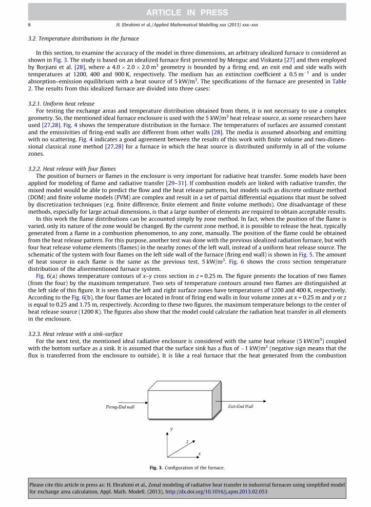
In this section, to examine the accuracy of the model in three dimensions, an arbitrary idealized furnace is considered asshown in Fig. 3. The study is based on an idealized furnace first presented by Menguc and Viskanta [27] and then employedby Borjiani et al. [28], where a 4.0 � 2.0 � 2.0 m3 geometry is bounded by a firing end, an exit end and side walls withtemperatures at 1200, 400 and 900 K, respectively. The medium has an extinction coefficient a 0.5 m�1 and is underabsorption–emission equilibrium with a heat source of 5 kW/m3. The specifications of the furnace are presented in Table2. The results from this idealized furnace are divided into three cases:
3.2.1. Uniform heat releaseFor testing the exchange areas and temperature distribution obtained from them, it is not necessary to use a complex
geometry. So, the mentioned ideal furnace enclosure is used with the 5 kW/m3 heat release source, as some researchers haveused [27,28]. Fig. 4 shows the temperature distribution in the furnace. The temperatures of surfaces are assumed constantand the emissivities of firing-end walls are different from other walls [28]. The media is assumed absorbing and emittingwith no scattering. Fig. 4 indicates a good agreement between the results of this work with finite volume and two-dimen-sional classical zone method [27,28] for a furnace in which the heat source is distributed uniformly in all of the volumezones.
3.2.2. Heat release with four flamesThe position of burners or flames in the enclosure is very important for radiative heat transfer. Some models have been
applied for modeling of flame and radiative transfer [29–31]. If combustion models are linked with radiative transfer, themixed model would be able to predict the flow and the heat release patterns, but models such as discrete ordinate method(DOM) and finite volume models (FVM) are complex and result in a set of partial differential equations that must be solvedby discretization techniques (e.g. finite difference, finite element and finite volume methods). One disadvantage of thesemethods, especially for large actual dimensions, is that a large number of elements are required to obtain acceptable results.
In this work the flame distributions can be accounted simply by zone method. In fact, when the position of the flame isvaried, only its nature of the zone would be changed. By the current zone method, it is possible to release the heat, typicallygenerated from a flame in a combustion phenomenon, to any zone, manually. The position of the flame could be obtainedfrom the heat release pattern. For this purpose, another test was done with the previous idealized radiation furnace, but withfour heat release volume elements (flames) in the nearby zones of the left wall, instead of a uniform heat release source. Theschematic of the system with four flames on the left side wall of the furnace (firing end wall) is shown in Fig. 5. The amountof heat source in each flame is the same as the previous test, 5 kW/m3. Fig. 6 shows the cross section temperaturedistribution of the aforementioned furnace system.
Fig. 6(a) shows temperature contours of x–y cross section in z = 0.25 m. The figure presents the location of two flames(from the four) by the maximum temperature. Two sets of temperature contours around two flames are distinguished atthe left side of this figure. It is seen that the left and right surface zones have temperatures of 1200 and 400 K, respectively.According to the Fig. 6(b), the four flames are located in front of firing end walls in four volume zones at x = 0.25 m and y or zis equal to 0.25 and 1.75 m, respectively. According to these two figures, the maximum temperature belongs to the center ofheat release source (1200 K). The figures also show that the model could calculate the radiation heat transfer in all elementsin the enclosure.
3.2.3. Heat release with a sink-surfaceFor the next test, the mentioned ideal radiative enclosure is considered with the same heat release (5 kW/m3) coupled
with the bottom surface as a sink. It is assumed that the surface sink has a flux of �1 kW/m2 (negative sign means that theflux is transferred from the enclosure to outside). It is like a real furnace that the heat generated from the combustion
Fig. 3. Configuration of the furnace.
Please cite this article in press as: H. Ebrahimi et al., Zonal modeling of radiative heat transfer in industrial furnaces using simplified modelfor exchange area calculation, Appl. Math. Modell. (2013), http://dx.doi.org/10.1016/j.apm.2013.02.053

0 0.5 1 1.5 2800
900
1000
1100
1200
y (m)
Gas
Tem
pera
ture
(K)
x=0.4 m
x=2 m
x=3.6 m
This Work FVM and 2D-ZM
Fig. 4. Comparison of results of this work with Borjiani et al. [28].
Fig. 5. Schematic of the furnace with four flames.
Table 2Specification of the furnace [28].
1Firing-end wall Temperature (K) 1200Exit-end wall Temperature (K) 400Other surface Temperatures (K) 900Furnace length (m) 4Furnace width (m) 2Furnace height (m) 2Heat source (kW/m3) 5Gas absorption coefficient (1/m) 0.5Firing-end wall emissivityOther surface emissivity
H. Ebrahimi et al. / Applied Mathematical Modelling xxx (2013) xxx–xxx 9
chamber, particularly from several burners, used for a load (e.g. reactor tubes and metal loads). Fig. 7 shows the temper-ature of gas zones in two cases of the first and second gas zones in z direction along the x elements, started from left. It isalso compared with P1-approximation model of radiation, a simple model of spherical harmonic used widely by re-searches. In this work, the method of previous work [22] using the FLUENT CFD-software applied to the ideal furnaceto predict the temperatures. According to the figure, there are some differences between the two models; however, thetrend is approximately the same. The difference could be due to the assumptions in P1 method or even reminded errorsoccurred in the zone method. Fig. 8 shows the temperature contours for two cross sections of x = 0.25 m (a) and x = 1.75(b). It is seen that the method could perfectly predict the temperatures of the enclosure. According to the figures, the max-imum temperature is decreased along the x direction. Although the sink, below y = 0.25 m, has a negative flux, the tem-peratures in the center of the furnace are so high. It is demonstrated that in the zone method all parameters includingradiation from all surface and gas elements, heat source and sink terms, and even gas and surface emissivities are consid-ered to find the final temperatures.
Please cite this article in press as: H. Ebrahimi et al., Zonal modeling of radiative heat transfer in industrial furnaces using simplified modelfor exchange area calculation, Appl. Math. Modell. (2013), http://dx.doi.org/10.1016/j.apm.2013.02.053

(a)Front side
(b)Right side
x (m)
y (m
)
1000
110012
00
900 600
800
500
1000
0 0.25 0.75 1.25 1.75 2.25 2.75 3.25 3.75 40
0.25
0.75
1.25
1.75
2
500
600
700
800
900
1000
1100
1200
z (m)
y (m
) 1000
1000
950
10001200
950
1050
950
1150
0 0.25 0.75 1.25 1.75 20
0.25
0.75
1.25
1.75
2
950
1000
1050
1100
1150
1200
Fig. 6. Cross section contours of temperature (K) in (a) front -side, z = 0.25 m; and (b) right side, x = 0.25 m. (Grids are 8�4�4 and the four flames are inx = 0.25 m with y = 0. 25 and 1.75 m and z = 0. 25 and 1.75 m.
1 2 3 4 5 6 7 8900
950
1000
1050
1100
1150
x elements
Tem
pera
tutu
re, K
z=2, Zone Methodz=2, P1-Approximationz=1, P1 Approximationz=1, Zone Method
Fig. 7. Comparison of temperatures of two series of z-direction elements along the x elements (gas zones from left to the right sides) obtained from thecurrent model with those of P1 method [22].
10 H. Ebrahimi et al. / Applied Mathematical Modelling xxx (2013) xxx–xxx
Please cite this article in press as: H. Ebrahimi et al., Zonal modeling of radiative heat transfer in industrial furnaces using simplified modelfor exchange area calculation, Appl. Math. Modell. (2013), http://dx.doi.org/10.1016/j.apm.2013.02.053

(a)
(b)
z (m)
y (m
)1110
1110
11001090
1080
1070
1060
1090
x=0.25 m
0.25 0.75 1.25 1.750.25
0.75
1.25
1.75
1050
1060
1070
1080
1090
1100
1110
z (m)
y (m
)
x=1.75 m
1070
1080
10601050
10101020
1030
1050
1010
1040
0.25 0.75 1.25 1.750.25
0.75
1.25
1.75
980
1000
1020
1040
1060
1080
Fig. 8. Temperature contours in the cross section of y–z in x = 0.25 m (a) and x = 1.75 m (b) from left side of idealized furnace with a heat source and asurface sink.
H. Ebrahimi et al. / Applied Mathematical Modelling xxx (2013) xxx–xxx 11
4. Conclusion
The zone analysis was used for modeling of radiative transfer in furnaces. This method is simple, exclusive non-differen-tial or integral form that can analyze the three-dimensional phenomena in the furnaces. A simple three-dimensional methodwas applied for calculation of direct exchange areas. This method is fast, simple and does not need integration for large num-ber of zones. The method gives better results as compared to the Hottel’s graphical and other numerical integration methods.After comparison of the results obtained from this simplified method (without integration) with numerical integral methods(Gaussian quadrature and Simpson’s Methods [26]), no considerable error was observed. For instance, the minimum error forcalculation of s1g1 is 18.5% with GQ, nine-points; while after the use of normalization and summation, it is decrease to 5.55%with the present method (about 70% decreasing in error). The computation time of the simplified method was much lessthan other methods. Nowadays with high speed computers available, the method could be used for calculation of exchangeareas. Graphical methods and algebraic relations rely on charts and graphs that have limited use in complex geometries. Sta-tistical methods such as Monte Carlo are cumbersome and time consuming whereas the present method yields reasonableresults is shorter computation time. It was shown that the method of exchange area calculation employed in energy balanceequations, is favorable as compared to other methods. So, a conclusion of the current paper is that the mentioned 3D zonemethod with the optimized parameters of calculating direct exchange areas could be properly replaced with other methodssuch as Monte Carlo and Discrete Ordinates methods. In fact, difficulty of using Zone method for complex geometries, errorsencountered from four to six fold integrals particularly self-zone radiation mode, and high amount of CPU time are the mainreasons that researchers do not prefer to use the method. They abundantly use other methods in commercial CFD softwares(e.g. FLUENT and ANSIS-CFX).
Please cite this article in press as: H. Ebrahimi et al., Zonal modeling of radiative heat transfer in industrial furnaces using simplified modelfor exchange area calculation, Appl. Math. Modell. (2013), http://dx.doi.org/10.1016/j.apm.2013.02.053

12 H. Ebrahimi et al. / Applied Mathematical Modelling xxx (2013) xxx–xxx
The accuracy of the model was tested as compared with literature data and acceptable results were obtained. Also modelcapability for accounting of flame position was tested and flame distributions in furnace were also considered by three-dimensional zone method. In the case of four flame zones, the maximum temperature was obtained in the center of flamesas 1200 K. The results show that the method is comprehensive and easy to implement for radiative phenomenon in furnaces.The method can be proposed for modeling of radiative heat transfer for several applications.
Appendix A. Supplementary data
Supplementary data associated with this article can be found, in the online version, at http://dx.doi.org/10.1016/j.apm.2013.02.053.
References
[1] M.F. Modest, Radiative Heat Transfer, second ed., McGraw Hill Inc., New York, 1993.[2] I. Teleaga, M. Seaïd, Simplified radiative models for low-Mach number reactive flows, Appl. Math. Model. 32 (2008) 971–991.[3] J.H. Jeans, The equations of radiation transfer of energy, Mon. Not. R. Astron. Soc. 78 (1917) 28–36.[4] S. Xia, L. Chen, F. Sun, Optimal paths for minimizing entransy dissipation during heat transfer processes with generalized radiative heat transfer law,
Appl. Math. Model. 34 (2010) 2242–2255.[5] S. Chandrasekhar, Radiative Transfer, Dover Publications, New York, 1960.[6] H.C. Hottel, E.S. Cohen, Radiant heat exchange in a gas-filled enclosure: allowance for non uniformity of gas temperature, AIChE J. 4 (1958) 3–14.[7] H.C. Hottel, A.F. Sarofim, Radiative Transfer, McGraw-Hill, New York, 1967.[8] J.A. Fleck, The calculation of nonlinear radiation transport by a Monte Carlo method: statistical physics, Methods Comput. Phys. 1 (1961) 43–65.[9] J.R. Howell, M. Perlmutter, Monte Carlo solution of thermal transfer through radiation media between gray walls, ASME J. Heat Transfer 86 (1964) 116–
122.[10] J.M. Rhine, R.J. Tucker, Modeling of Gas-Fired Furnaces and Boilers and Other Industrial Heating Processes, McGraw-Hill, London, 1991.[11] E.S. Cohen, Effect of gas temperature gradients on radiant heat transmission. Sc. D. Thesis, Mass. Inst. Tech., Cambridge, 1955.[12] R. Siegel, J.R. Howell, Thermal Radiation Heat Transfer, third ed., Hemisphere Publishing Corporation, New York, 1992.[13] H.B. Becker, A mathematical solution for a gas-to-surface radiative exchange area for a rectangular parallelpiped enclosure containing a gray gas, ASME
J. Heat Transfer 99 (1977) 203–207.[14] Tucker, Direct exchange areas for calculation radiation transfer in rectangular furnaces, ASME J. Heat Transfer 108 (1986) 707–710.[15] J. Sika, Evaluation of direct exchange areas for a cylindrical enclosure, ASME J. Heat Transfer 113 (1991) 1040–1044.[16] W. Tian, W.K.S. Chiu, Calculation of direct exchange areas for non-uniform zones using a reduced integration scheme, ASME J. Heat Transfer 125 (2003)
839–844.[17] W. Tian, W.K.S. Chiu, Hybrid method to calculate direct exchange areas using the finite volume method and midpoint integration, ASME J. Heat
Transfer 127 (2005) 911–917.[18] M.F. Modest, Radiative equilibrium in a rectangular enclosure bounded by gray walls, J. Quant. Spectrosc. Radiat. Transfer 15 (1975) 445–461.[19] D.O. Marlow, Modelling direct-fired annealing furnaces for transient operations, Appl. Math. Model. 20 (1996) 34–40.[20] J. Noble, The zone method: explicit matrix relations for total exchange areas, Int. J. Heat Mass Transfer 18 (1974) 261–269.[21] M.H.N. Naraghi, B.T.F. Chung, A unified matrix formulation for the zone method: a stochastic approach, Int. J. Heat Mass Transfer 28 (1985) 245–251.[22] H. Amirshaghaghi, A. Zamaniyan, H. Ebrahimi, M. Zarkesh, Numerical simulation of methane partial oxidation in the burner and combustion chamber
of autothermal reformer, Appl. Math. Model. 34 (2010) 2312–2322.[23] W.E. Lobo, J.E. Evans, Heat transfer in radiant section of petroleum heaters, Trans. A.I. AIChE 35 (1939) 743–751.[24] R. Nogay, Better design method for fired heaters, Hyd. Proc. (1985) 50–61.[25] M.S. Liu, C.K. Choi, C.W. Leung, Startup analysis of oil-fired furnace-the smoothing Monte Carlo model approach, Heat Mass Transfer 37 (2001) 449–
457.[26] B. Carnahan, H.A. Luther, J.O. Wilkes, Applied Numerical Methods, John Wiley, New York, 1969.[27] M. Menguc, R. Viskanta, Radiative transfer in three-dimensional rectangular enclosures containing inhomogeneous, anisotropically scattering media, J.
Quant. Spectrosc. Radiat. Transfer 33 (1986) 533–549.[28] M.N. Borjiani, H. Farhat, M.S. Radhouani, Analysis of radiative heat transfer in a partitioned idealized furnace, Numer. Heat Transfer Part A 44 (2003)
199–218.[29] C. Inman, The use of simple isothermal model as a guide to flame behaviour in a glass furnace, J. Inst. Fuel 42 (1969) 451–454.[30] S.R. Turns, An Introduction to Combustion, Concepts and Applications, second ed., McGraw Hill, New York, 2002.[31] P.J. Stopford, Recent applications of CFD modelling in the power generation and combustion industries, Appl. Math. Model. 26 (2002) 351–374.
Please cite this article in press as: H. Ebrahimi et al., Zonal modeling of radiative heat transfer in industrial furnaces using simplified modelfor exchange area calculation, Appl. Math. Modell. (2013), http://dx.doi.org/10.1016/j.apm.2013.02.053