
ZODIAC CH 601 - Zenith Aircraft Company · ZODIAC CH 601 Series Kit Aircraft ... With a square,...
17
ZODIAC CH 601 Series Kit Aircraft THE FOLLOWING IS A DRAFT MANUAL This manual has been written and published strictly for informational purpose. It has been prepared as a guide to facilitate the assembly of the ZODIAC CH 601 kit aircraft. It is published to supplement (and not replace) the Zenair drawings and manuals. If a discrepancy arises between this informational manual and the Drawings, the Drawings always take precedence. All pictures, diagrams, drawings or graphs, are used for general identification only, and are not to be taken to represent technical drawings or replicas of exact parts. You should not consider the educational material in the manual to be the practice of general aviation nor is it intended for this manual to be a complete account of sheet metal aircraft technology: It is limited to the scope of the ZODIAC CH 601 aircraft assembly This manual is not intended to replace, substitute for or supersede any technical information contained in the ZODIAC CH 601 Drawings and Manuals by Chris Heintz, or other designer’s specifications. Zenith Aircraft Company (ZAC) nor its authors guarantees the accuracy or completeness of any information published herein and neither ZAC nor its authors shall be responsible for any errors, omissions, or damages arising out of use of this information. This guide is printed with the understanding that ZAC and its authors are supplying information but are not attempting to render engineering or other professional services. If such services are required, the assistance of an appropriate professional should be sought. Copyright, 1995-2001 Zenith Aircraft Company
Transcript of ZODIAC CH 601 - Zenith Aircraft Company · ZODIAC CH 601 Series Kit Aircraft ... With a square,...

ZODIAC CH 601Series Kit Aircraft
THE FOLLOWING IS A DRAFT MANUAL
This manual has been written and published strictly for informational purpose. It hasbeen prepared as a guide to facilitate the assembly of the ZODIAC CH 601 kit aircraft. Itis published to supplement (and not replace) the Zenair drawings and manuals. If adiscrepancy arises between this informational manual and the Drawings, the Drawingsalways take precedence.
All pictures, diagrams, drawings or graphs, are used for general identification only, andare not to be taken to represent technical drawings or replicas of exact parts. You shouldnot consider the educational material in the manual to be the practice of general aviationnor is it intended for this manual to be a complete account of sheet metal aircrafttechnology: It is limited to the scope of the ZODIAC CH 601 aircraft assemblyThis manual is not intended to replace, substitute for or supersede any technicalinformation contained in the ZODIAC CH 601 Drawings and Manuals by Chris Heintz,or other designer’s specifications.
Zenith Aircraft Company (ZAC) nor its authors guarantees the accuracy or completenessof any information published herein and neither ZAC nor its authors shall be responsiblefor any errors, omissions, or damages arising out of use of this information. This guide isprinted with the understanding that ZAC and its authors are supplying information but arenot attempting to render engineering or other professional services. If such services arerequired, the assistance of an appropriate professional should be sought.
Copyright, 1995-2001 Zenith Aircraft Company

Zenith Aircraft Company Print Date: 10/25/01 ZODIAC CH 601www.zenithair.com HD / HDS / UL
REAR FUSELAGE ASSEMBLY WORK REPORT
Step # Check Parts Inventory Qty.1 [ ] 6F2-1 Front H.T. Frame .032 11 [ ] 6F2-2 Angle .032 12 [ ] N66 Plastic Bearing (Fairlead) Material t=.125 13 [ ] 6F2-3 Rear H.T. Frame .032 13 [ ] 6F2-4 Angle .032 14 [ ] 6F2-6 Rear Panel .025 15 [ ] 6F1-1 Rear Bottom Skin .016 1
PRE-DRILLED FOR L ANGLES ANDSIDE LONGERONS.
5 [ ] L Angles 66 [ ] 6F1-2 Rear Bottom End Skin .025 17 [ ] 6F3-2B Lower Rudder Hinge (Bottom) .063 19 [ ] SHIM 20mm t= .040 19 [ ] SHIM 20 x 92 t= .063 113 [ ] 6F1-5 Lower Middle Longeron .040 1L & 1R14 [ ] 6F1-3 Rear Longerons .040 415 [ ] 6F1-4 Lower Longeron Doubler .040 216 [ ] 6F1-6 Cross Stiffener .025 117 [ ] 6F3-3 Rear Middle Side Skins .016 2
PRE-DRILLED FOR L ANGLES ANDBOTTOM LONGERONS.
21 [ ] 6F2-7 H.T. Attachment Bracket (Rear) .063 122 [ ] 6F2-8 H.T. Attachment Bracket (Front) .063 223 [ ] L Angles 523 [ ] Gussets .016 524 [ ] 6F3-1 Upper Rudder Hinge .125 125 [ ] 6F3-2A Lower Rudder Hinge (top) .063 126 [ ] 6F4-1 Cable Outlet Fairing .016 2
SIGNATURES: Builder _____________________________________ date
Inspector ____________________________________ date

Zenith Aircraft Company Print Date: 10/25/01 ZODIAC CH 601www.zenithair.com HD / HDS / UL
HORIZONTAL TAIL (H.T.) FRAME ASSEMBLY F-3Add the angle at the bottom to set the height of the of the assemblies.
1. Cleco the Angle 6F2-2 at the bottom of the Front H. T. Frame 6F2-1 REFERENCE: 6-F-2 CLAMP: 6F2-2 to 6F2-1 CHECK: a) The height is 376; measured from outside to outside between 6F2-2 and 6F2-1
b) With a square, check that the Bottom Angle 6F2-2 is at 90 degrees with thesides flanges of 6F1-2
c) The Angle is centered on the aircraft center line (the Angle is centered left andright on the Frame).
RIVET LINE: The rivet line is located as the split middle of the overlap of flange 6F2-2over the web 6F2-1 (midway between the bottom edge of 6F2-1and the top edge of 6F2-2). PITCH: A5 pitch 20 CUT: On the bottom flange, taper the ends of the Angle 6F2-2 to match the BottomFuselage Skin. TIP: Draw a center line on the four flanges of the assembly. SUGGESTION: Drill a #40 hole on the aircraft center line (longitudinal axis) in thebottom flange; this will help center the assembly to the Bottom Skin.
2. Cable Fairlead (1/8” plastic material), contour (file) the Fairlead to match the curvature of
the lightning hole on the Front H. T Frame 6F2-1 REFERENCE: Top left diagram on 6-F-2 MATERIAL: 1/8” plastic: Nylon or Teflon. RIVET: 2A4
3. Cleco the Angle 6F2-4 at the bottom of the Rear H.T. Frame 6F2-3
REFERENCE: 6-F-2 CLAMP: 6F2-4 to 6F2-3 CHECK: a) The height is 360; measure from outside to outside between 6F2-3 and 6F2-4
b) With a square, check that the Bottom Angle 6F2-4 is at 90 degrees with thesides flanges of 6F2-3
Wait to drill the center hole in the bottom flange of the Angle 6F2-4, the 30mm flange is toowide!
4. Cut the opening in the Rear Panel (top) 6F2-6
REFERENCE: 6-F-2 CUT: Use a hole saw or fly cutter set for diameter = 60mm to cut the two outside holes.Connect the two holes on by their tangent lines, cut on the line with hand snips. File to asmooth finish.

© Zenith Aircraft Company: Mexico Memorial Airport, PO Box 650, Mexico, MO 65265 USA (573) 581-9000 FAX: 573-581-0011
Description:
REAR FUSELAGE FRAMESZODIACCH 601
Drawing Rev.
1st Edition:7-96(3/98)
F-4F-4
ZODIAC CH 601
6F2-2ANGLEt=.032l=210
6F2-1FRONT H.T. FRAMEt=.0251 REQ.
PLASTIC FAIRLEAD
CLECO:A5 PITCH 20
6F2-4ANGLEt=.025l=100
6F2-3FRONT H.T. FRAMEt=.0251 REQ.
RIVET 2 A4
376
358
CLECO:A5 PITCH 20
6F2-6REAR TOPPANELt=.0251 REQ.
150 150
30mm RADIUS
Zenith Aircraft Company Print Date: 10/25/01 ZODIAC CH 601www.zenithair.com HD / HDS / UL
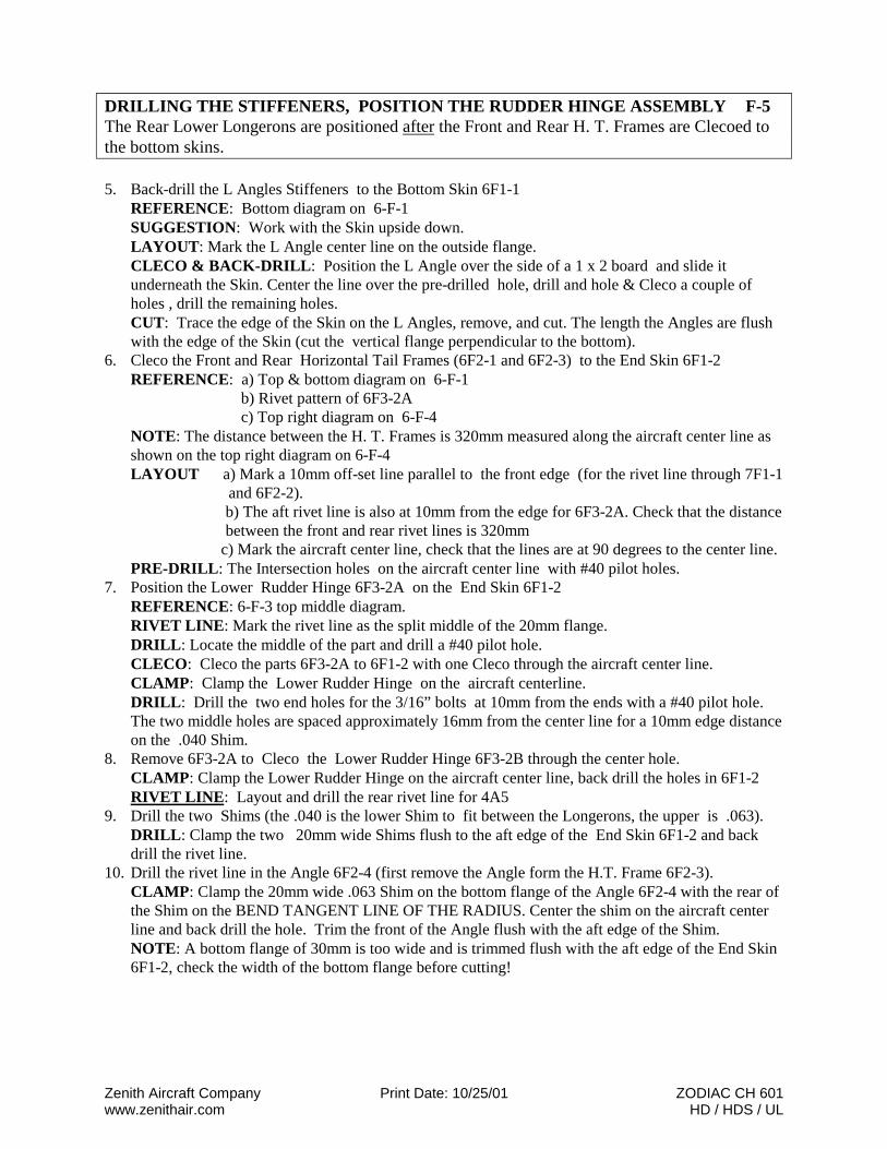
DRILLING THE STIFFENERS, POSITION THE RUDDER HINGE ASSEMBLY F-5 The Rear Lower Longerons are positioned after the Front and Rear H. T. Frames are Clecoed tothe bottom skins. 5. Back-drill the L Angles Stiffeners to the Bottom Skin 6F1-1
REFERENCE: Bottom diagram on 6-F-1 SUGGESTION: Work with the Skin upside down. LAYOUT: Mark the L Angle center line on the outside flange. CLECO & BACK-DRILL: Position the L Angle over the side of a 1 x 2 board and slide itunderneath the Skin. Center the line over the pre-drilled hole, drill and hole & Cleco a couple ofholes , drill the remaining holes. CUT: Trace the edge of the Skin on the L Angles, remove, and cut. The length the Angles are flushwith the edge of the Skin (cut the vertical flange perpendicular to the bottom).
6. Cleco the Front and Rear Horizontal Tail Frames (6F2-1 and 6F2-3) to the End Skin 6F1-2 REFERENCE: a) Top & bottom diagram on 6-F-1
b) Rivet pattern of 6F3-2A c) Top right diagram on 6-F-4
NOTE: The distance between the H. T. Frames is 320mm measured along the aircraft center line asshown on the top right diagram on 6-F-4 LAYOUT a) Mark a 10mm off-set line parallel to the front edge (for the rivet line through 7F1-1
and 6F2-2). b) The aft rivet line is also at 10mm from the edge for 6F3-2A. Check that the distancebetween the front and rear rivet lines is 320mm
c) Mark the aircraft center line, check that the lines are at 90 degrees to the center line. PRE-DRILL: The Intersection holes on the aircraft center line with #40 pilot holes.
7. Position the Lower Rudder Hinge 6F3-2A on the End Skin 6F1-2 REFERENCE: 6-F-3 top middle diagram. RIVET LINE: Mark the rivet line as the split middle of the 20mm flange. DRILL: Locate the middle of the part and drill a #40 pilot hole. CLECO: Cleco the parts 6F3-2A to 6F1-2 with one Cleco through the aircraft center line. CLAMP: Clamp the Lower Rudder Hinge on the aircraft centerline. DRILL: Drill the two end holes for the 3/16” bolts at 10mm from the ends with a #40 pilot hole.The two middle holes are spaced approximately 16mm from the center line for a 10mm edge distanceon the .040 Shim.
8. Remove 6F3-2A to Cleco the Lower Rudder Hinge 6F3-2B through the center hole.CLAMP: Clamp the Lower Rudder Hinge on the aircraft center line, back drill the holes in 6F1-2RIVET LINE: Layout and drill the rear rivet line for 4A5
9. Drill the two Shims (the .040 is the lower Shim to fit between the Longerons, the upper is .063).DRILL: Clamp the two 20mm wide Shims flush to the aft edge of the End Skin 6F1-2 and backdrill the rivet line.
10. Drill the rivet line in the Angle 6F2-4 (first remove the Angle form the H.T. Frame 6F2-3).CLAMP: Clamp the 20mm wide .063 Shim on the bottom flange of the Angle 6F2-4 with the rear ofthe Shim on the BEND TANGENT LINE OF THE RADIUS. Center the shim on the aircraft centerline and back drill the hole. Trim the front of the Angle flush with the aft edge of the Shim.NOTE: A bottom flange of 30mm is too wide and is trimmed flush with the aft edge of the End Skin6F1-2, check the width of the bottom flange before cutting!
© Zenith Aircraft Company: Mexico Memorial Airport, PO Box 650, Mexico, MO 65265 USA (573) 581-9000 FAX: 573-581-0011
Description:
L STIFFENER OF BOTTOMLOWER RUDDER HINGE
ZODIACCH 601
Drawing Rev.
1st Edition:7-96(3/98)
F-6F-6
ZODIAC CH 601
L
L
L
L
BACK DRILL ANGLESTHROUGH PRE-DRILLED SKIN,THEN CUT L ANGLE FLUSHWITH THE SKIN
6F1-6
6F3-2ALOWER RUDDERHINGEt=.063
3/16” HOLE8mm RADIUS
BENT11 m
m11
mm
3/16” HOLE8mm RADIUS
6F3-2BLOWER RUDDERHINGEt=.063
LOWER RUDDERHINGE ASSEMBLY
AN3
BUSHING 3.2mm
6F3-2A
.063 SHIM
6F2-4
6F3-2B
LONGERON
6F1-1
6F3-2A
.063 SHIM
6F2-4
.040 SHIM
6F1-2
6F3-2B
BENT

Zenith Aircraft Company Print Date: 10/25/01 ZODIAC CH 601www.zenithair.com HD / HDS / UL
POSITION THE END SKIN & THE LOWER MIDDLE LONGERONS F-7When connecting the rear fuselage to the wing center section, the Lower Middle Longerons 6F1-5 will overlap on top of the Rear Zee 6V7-1 with the Bottom Skin inbetween Rear Zee and theBottom Skin 6V11-2. To allow the Bottom Skin 6F1-1 to overlap the full width of the Rear Zeeflange, the Lower Middle Longeron 6F1-5 is moved back to avoid interference with the bendradius of the lower Flange.
11. Back-drill the Rear Bottom Skin 6F1-1 to the End Skin 6F1-2 REFERENCE: 6-F-1, 6-F-4 NOTE: At the overlap the sides bow in approximately 8mm from the straight lineconnecting the front and aft corners of the fuselage. CLAMP: 6F1-1 overlaps on top of 6F1-2 CHECK: a) The overall length = 2544 (measure along the center line).
b) Check that the End Skin is centered on the aircraft center line! BACK-DRILL: with #40 pilot holes.
12. Cleco the Front H. T. Frame assembly 6F2-2 to the Bottom Skin 6F1-2 REFERENCE: 6-F-4 CLECO: Take the H.T. Frame apart and Cleco the Angle 6F2-2 to End Skin 6F1-2 throughtheir common center hole. CLAMP: The Angle is parallel with the front edge. BACK-DRILL: a) With #30
b) Open up the aft rivet line in 6F1-1 with #30 holes.13. Back drill the Lower Middle Longeron 6F1-5 to the Bottom Skin 6F1-1
REFERENCE: 6-F-1, 6-F-6, 6-F-10 CUT: a) Trace and snip the bottom flange to match the front corner the Skin 6F1-1
b) Snip the side flange at 79 degrees (inside angle). See top right diagram on 6V7 NOTE: The angle between the rear fuselage section and the center wing section isdetermined by the angle of the bottom flange of the Rear Zee 6V7-1 EDGE DISTANCE: The pre-drill rivet lines in the sides of the Bottom Skin are at 3/8” fromthe edge. LAYOUT: Mark a 3mm off-set line along the front edge of the Skin 6F1-1 DRILLING TIP: Place the Longeron underneath the Bottom Skin and back-drill fromthe top through the pre-drilled Skin. (the overlap order is reversed to simplify drilling byworking from the top). CLAMP: The front edge of the Longeron on the 3 mm off-set line. CHECK: a) The distance across the Longerons 6F1-5 is 1055mm measured from
outside to outside to fit inside the Rear Pick Up Channels 6F6-3 as shown ondrawing 6-F-6
b) The first L Angle at STA 594 overlaps on top of the Longeron BACK-DRILL: With #40
Wait to drill the front and inside rivet line: The front rivet line is riveted through the RearZee and the inside rivet line into the Lower Front Longeron 6F5-4 as shown on drawing6F10. The side flange is drilled later through the Side Skins.

© Zenith Aircraft Company: Mexico Memorial Airport, PO Box 650, Mexico, MO 65265 USA (573) 581-9000 FAX: 573-581-0011
Description:
POSITION LONGERONZODIACCH 601
Drawing Rev.
1st Edition:7-96(3/98)
F-8F-8
ZODIAC CH 601
6F2-4ANGLEt=.032
6F1-2BOTTOM END SKINt=.0251 REQ.
320 mm.
between rivets
20 mm.OVERLAP
6F1-1REAR BOTTOM SKINt=.0251 req.
6F1-5LOWER MIDDLE LONGERONt=.040
6F1-5LONGERON
SIDE VIEW
The edge of the bottom skinstops at the bend tangent
line of the longeron.SKIN
Trim the longeron
1055
3 mm. from end

Zenith Aircraft Company Print Date: 10/25/01 ZODIAC CH 601www.zenithair.com HD / HDS / UL
REAR LONGERONS & LONGERONS DOUBLERS F9The Rear Longerons are positioned butt to butt with the Longerons Doublers and Clamped to theside flange of the Front and Rear H.T. Frames.
14. The Rear Longerons 6F1-3 are installed with the H.T. Frame assembly Clecoed to theFuselage Bottom Skins 6F1-1 and 6F1-2 REFERENCE: 6-F-1, 6-F-3 RIVET: The Angles to the H.T Frame assemblies: 6F2-1 to 6F2-2 and 6F2-3 to 6F2-4 CLECO: The Front and Rear Horizontal Tail Frames to the Bottom Skins 6F1-1and 6F1-2 DRILLING TIP: Place the Longeron underneath the Bottom Skin and back-drill from thetop through the pre-drilled Skin. (the overlap order is reversed to simplify drilling by workingfrom the top). CLAMP: a) Butt the Longerons 6F1-3 and 6F1-5 end to end.
b) Clamp the Longerons 6F1-3 to the HT frames and to the End Skin. CHECK: The Skin stops at the Longeron bend tangent line, see bottom right diagram on6-F-3 (edge distance of 3/8”). BACK-DRILL : With #30 CUT: The end of the Longerons 6F1-3 flush with the End Skin 6F1-2
15. Position the Lower Longeron Doubler 6F1-4 to overlap on top of 6F1-5 and 6F1-3
REFERENCE: 6-F-1 POSITION: a) 6F1-4 overlaps on top of 6F1-5 & 6F1-3
b) the front the Doubler is set back 100mm from the front edge of the BottomSkin
CLAMP: a) 6F1-4 to 6F1-3 along the side flange. b) 6F1-4 to 6F1-5 c) 6F1-5 to 6F1-1 along the bottom flange.
PITCH: a) 5A5 in 6F1-3, 3A5 pitch 15 at front ends of 6F1-3 and at the rear end of 6F1-5,A5 pitch 30 in-between.
b) Remember the L angle! 16. Position the Cross Stiffener 6F1-6
REFERENCE: 6-F-1 PITCH: 3A5 into the Lower Middle Longerons 6F1-5
TIP: Wait to rivet 6F1-4 through 6F1-5, it is riveted later together with the Fuselage-Wing
Fairing 6E1-1. The side flange is drilled later through the Side Skin 6F3-3.

© Zenith Aircraft Company: Mexico Memorial Airport, PO Box 650, Mexico, MO 65265 USA (573) 581-9000 FAX: 573-581-0011
Description:
BOTTOM SKIN & STIFFENERSZODIACCH 601
Drawing Rev.
1st Edition:7-96(3/98)
F-10F-10
ZODIAC CH 601
6F1-4LOWER LONGERON DOUBLERt=.0402 req.
A5 RIVETS A4 R
IVETS
6F1-3REAR LONGERONt=.0404 req.
100 mm
6F1-3REARLONGERON
SIDESKIN
A4 RIVETS
L
L
A4 PITCH 40
BOTTOM OF SIDE SKINFLUSH TO LONGERON END
L ANGLE IS ATTHE END OF THEDOUBLER
TRIM SHIM TO FIT BE-TWEEN LONGERONS
.040 SHIM
REARLONGERON
6F3-3REAR MIDDLE SIDESKINt=.0402 req.

Zenith Aircraft Company Print Date: 10/25/01 ZODIAC CH 601www.zenithair.com HD / HDS / UL
THE REAR MIDDLE SIDE SKINS F-11 Use the pre-drilled holes for the H.T. Frame to reference the Side Skins on the fuselageassembly. 17. Back-drill the H.T frames through the pre-drilled pilot holes in the Rear Middle Side Skins
6F3-3 REFERENCE: 6-F-3, 6-F-4, 6-F-15 NOTE: a) The H. T. Frames are set at 90degress to the top edge of the Skin.
b) The L Angles stations are given along the bottom edge. c) The L Angles are at 90 degrees to the top edge of the Skin.
CLAMP: a) The Side Skin to the Front and Rear H. T. Frames. b) The bottom edge of the Skin stops at the bent tangent line of the Longeron. c) The aft edge of the Skin is flush with the End Skin 61-2
SUGGESTION: To support the Side Skins at the front, clamp them to a temporary woodframe or large cardboard box. Work with one Side Skin at a time! CHECK: i.) The center line of the H.T. Frames is visible through the pre-drilled holes in
the skin. ii.) The bottom of the Skin stops at the bent tangent line of the Longeron.
iii.) The aft edge of the Skin is flush with the aft edge of the End Skin (the frontbottom corner also lines up with the front of the fuselage skin).
BACK-DRILL & CLECO: Start at the rear with #30 COMMENT: The Rudder Stop overlaps the Side Skins and is riveted to the Rear H.T.Frame. Plan for a “no rivet zone” at the bottom, see 6-F-15
18. Add the diagonal L angles between the two H.T. frames.
TACK RIVETING:This is the same technique used to hold the Rear Top Skin 6V8-1 to the Main spar. On theFuselage the tack rivets hold the Longeron 6F1-3 to the Side Skin. The rivet line through theLongeron is drilled later through the Rear Top Skin 6F14-1

© Zenith Aircraft Company: Mexico Memorial Airport, PO Box 650, Mexico, MO 65265 USA (573) 581-9000 FAX: 573-581-0011
Description:
REAR PANEL & LONGERONZODIACCH 601
Drawing Rev.
1st Edition:7-96(3/98)
F-12F-12
ZODIAC CH 601
REAR PANEL6F2-6
REAR LONGERON6F1-3
SIDE SKINSUPPORT BOX(JIG)
A4PITCH 20
A4 PITCH 40
L A4 PITCH 20
TRIM

Zenith Aircraft Company Print Date: 10/25/01 ZODIAC CH 601www.zenithair.com HD / HDS / UL
REAR PANEL & REAR LONGERONS F-13The Rear Longerons are held in place with tack (flush countersunk) riveted to the Side Skin.The Longeron rivet line is drilled later through the Rear Top Skin 6F14-1
19. Cleco the Rear Top Panel 6F2-6 on top of the H.T. Frame assemblies. REFERENCE: 6-F-4 LAYOUT: Mark and extend flange center line of the H.T. Frame on the inside of the SideSkins; this is to locate the flange center line when the Rear Top Panels are dropped in place. POSITION: Position the end of the Top Panel flush with the end of the Side Skins.Transfer the H.T Frame center line previously marked on the Side Skin to the Top Panel.Connect the left and right mark with a straight line to mark the flange center line of the H.T.Frame. CHECK: 320mm between center lines. DRILL & CLECO: The intersection hole of the aircraft center line with the H.T. Framewith #30
20. Position the upper Rear Longerons 6F1-3 on the Top Panel 6F2-6 REFERENCE: 6-F-4, tack rivets. CUT: Position the inner corner of the bottom flange of the Longeron flush with the aft edgeof the Top Plate. Trim the side flange to fit the Side Skin without reducing the overall lengthof the Longeron. CLAMP: a) The Longerons to the Side Skins.
b) Clamp the Top Panel to the Longerons through the middle cutout. CHECK FOR TWIST: With a digital level (protractor) it is easy to see if the sides areparallel. If a large carpenter square is used, hold it in the same position on both sides of thefuselage. Readjust the clamps if necessary! CLECO: a) Flush tack rivets are used where the Top Skin will overlap the Side Skin. Start
at 600 from the end and pitch of 300, see bottom right diagram on 6-F-4 b) Drill and Cleco the Side Skins to the Longerons on the distance inbetween the
H.T. Attachment Brackets 7F2-7 and 6F2-8 with #30. Remember the “no rivetzone” for 6F2-7 & 6F2-8 (The Rear Top Skin will extend approximately100mm aft of the Bulkhead 6F11-1).

© Zenith Aircraft Company: Mexico Memorial Airport, PO Box 650, Mexico, MO 65265 USA (573) 581-9000 FAX: 573-581-0011
Description:
H.T. BRACKETS, SIDE STIFFENERSZODIACCH 601
Drawing Rev.
1st Edition:7-96(3/98)
F- 4F-14
ZODIAC CH 601
20 20
20
20
20
20
7 A5
6F2-8H.T. ATTACH.BRACKET (FRONT)t=.0632 REQ.
6F2-7H.T. ATTACH.BRACKET(REAR)t=.0632 REQ.
A5 RIVETS A5 RIVETS
GUSSET
SKINL STIFFENERSL STIFFENERSGUSSETt=.016

Zenith Aircraft Company Print Date: 10/25/01 ZODIAC CH 601www.zenithair.com HD / HDS / UL
H.T. BRACKETS, SIDE STIFFENERS & GUSSET F-15 The vertical rivet line of the H.T. Attachment Brackets Rivet on the flange center line of the H.T.Frame and the horizontal rivet line into Longeron.
21. Cleco the Rear H.T. Attachment Brackets 6F2-7 to the fuselage assembly. REFERENCE: 6-F-2, 6-F-4, 6-F-15 PRE-DRILL: Layout and pre-drill the Brackets with #40 pilot holes (the horizontal rivetline through the Longeron is 35mm from the top of the Bracket. CLAMP: The Brackets to the Fuselage with the pre-drilled holes on the flange center line. BACK-DRILL & CLECO: With #20
22. Cleco the two parallel L Angles flush with the sides of the cutout on the Rear Top Panel6F2-6 with an end-hole in each H.T. Frame. REFERENCE: 6-F-4 NOTE: The length of the L Angle is cut long enough to overlap the Front and Rear H.T.Frames. CUT: The L angle overlaps on top of Longeron, taper the aft bottom flange of the L Anglesto position the Angles flush with the sides the cutout. CLAMP: The L Angles to overlap on top of the Longerons; they should be 60mm apart. DRILL & CLECO: With #30
23. Drill the Longerons to the Top Panel 6F2-6PITCH: A4 pitch 20, (with a rivet in the front H.T. Frame) Rivet the Longeron beforeriveting the two L Angles to avoid interference of the rivet head with the side of the L angle.NOTE: Wait to drill the front end hole through the Panel. This is drilled later through theBulkhead B6 positioned along the front edge of the Panel as shown on drawings 6-F-4 and6-F-11
24. Drill the front and rear rivet lines in the top flange of the H. T Frames in the middle andbetween the L angles and the Longerons. A4 PITCH 20
25. Add the L Stiffeners on the Side Skin, the Gussets at the top of the L Angles slideunderneath the L Angles and the Longeron.CUT: Cut the length of 3 L Angles to overlap the bottom Longerons and to fit underneath theTop Longerons.CUT: The top of the 2 forward L angles is ¾” below the bottom flange of the TopLongeron to allow clearance for Extrusion 6F1-3 installed later.POSITION: Slide the .016 Gusset underneath the L angle and the Longeron.PITCH IN GUSSET: 2 holes in the L angle, 3 holes in the Longerons (see F-14).
RUDDER HINGE BUSHING:The S.25x.028” 4130 steel bushing is held in place by the AN3 bolt through 6F3-2A and6F3-2B, a similar arrangement is used on the two Upper Bearing 6T4-3 riveted to the Rudder.The Upper Rudder Hinge 6F3-1 and the Vertical Tail Horn 6T5-3 as both drilled with a ¼” holeto turn around the steel bushing. A self locking nylon nut is used to secure the bolt (and thebushing) to prevent them from turning or spinning in the holes. Only the parts 6F3-1 and 6T5-3turn around the bushing.

© Zenith Aircraft Company: Mexico Memorial Airport, PO Box 650, Mexico, MO 65265 USA (573) 581-9000 FAX: 573-581-0011
Description:
POSITION HINGESZODIACCH 601
Drawing Rev.
1st Edition:7-96(3/98)
F-16F-16
ZODIAC CH 601
6F3-1UPPER RUDDER HINGEt=1/8”1 REQ.
3 A5+ 2 AN3BOLTS
6F1-3
6F2-3
REAR H.T.FRAME LONGERON
TIE-DOWN RING
PLASTIC FAIRLEAD
SKIN CABLE
30 mm.29 mm.
6 mm.RADIUS
5 mm.6F2-3
DOWEL(PARALLEL WITHTHE SIDE SKIN!)
6F2-1
100380 m
m.
90 DEG.
1/4” HOLE
11 mm.
AN3-5ABEND

Zenith Aircraft Company Print Date: 10/25/01 ZODIAC CH 601www.zenithair.com HD / HDS / UL
UPPER RUDDER HINGE, CABLE FAIRLEAD F-17 The straight line connecting the upper and lower hinges is parallel with the aft edge of the SideSkins.
26. Drill a 1/8” pilot hole in the Lower Rudder Hinges 6F3-2A and 6F3-2B checking for aminimum of 8mm edge distance to the sides of the Hinges. Center punch the hole for betteraccuracy before drilling!CLECO: The Lower Rudder Hinges to the fuselage.
27. Position the Upper Rudder Hinge 6F3-1 NOTE: The Rudder Spar 6T3-4 is installed parallel with the end of the Side Skins 6F3-4 .When the Top Longeron is level the bottom hinge is offset by 100mm from a vertical plumline through top hinge. LAYOUT: Drill the hinge pivot for a hole #40 pilot hole. POSITION: a) Feed a long steel welding rod (straight wire) through the top and bottom
hinge plates. Clamp the Upper Rudder Hinge at the 100mm off-set using alarge square reference on the top of the Side Skins. b) Stand back, looking at the fuselage from the rear, and check that the rod isvertical .
DRILL: The 5 holes (with good edge distance in 6F1-3 underneath). The two rear holes aredrilled for an AN3 bolt
28. Position the Cable Outlet Fairings 6F4-1 on the Fuselage Sides 6F3-3
REFERENCE: Bottom right diagrams on 6-F-4 CUT: The slot in the Side Skin 6F3-3 TRIM: Position the Fairing level with the top edge of the Side skin and trace the undersideof the fuselage to trim any access material off the Fairing. DRILL & CLECO: The Cable Outlet Fairing over the slot (slide the Fairing between theLongeron and the Skin to back drill through the existing holes in the Longeron – the fore andaft positions of the Fairing can be moved to adjust the edge distance of the end holes). BEARING MATERIAL: Remove the Cable Outlet Fairing , position the plastic Fairleadmaterial on the inside of the fuselage against the Side Skin and back drill the top and bottomrivet line. In the middle of the slot drill a 1/8” for the rudder cable.
Remove the Plastic Fairlead and elongate the 1/8” hole to align with the actual path of therudder cable: insert the drill in the 1/8” hole and with the drill at high speed slowly bring thedrill from a vertical position to a diagonal position, (as close as the chuck will allow youbefore touching the Fairlead!). By exaggerating the elongation the cable will choose its ownpath with the least resistance or change of angular deflection.
- end –
08/01: ZAC Engineering/601 manual/fuselage/REAR-F.doc© Zenith Aircraft Company


![PURCHASE AGREEMENT BETWEEN ZODIAC SEATS … · PURCHASE AGREEMENT . BETWEEN . ZODIAC SEATS UK LIMITED . AND [customer name] FOR THE SUPPLY OF [seat type] FITTED TO [aircraft type]](https://static.fdocuments.net/doc/165x107/5b50a3f47f8b9a5a6f8ee001/purchase-agreement-between-zodiac-seats-purchase-agreement-between-zodiac.jpg)