Zimmer Natural Nail System...femur should be taken preoperatively and evaluated for length, canal...
25
Zimmer ® Natural Nail ® System Cephalomedullary Nail Surgical Technique STANDARD
Transcript of Zimmer Natural Nail System...femur should be taken preoperatively and evaluated for length, canal...

Zimmer®
Natural Nail®
SystemCephalomedullary Nail
Surgical Technique
STANDARD


Zimmer® Natural Nail® System Cephalomedullary Nail Surgical Technique - Standard 1
Zimmer Natural Nail System Cephalomedullary Nail Surgical Technique - Standard
Table of Contents
Product Overview 2
Implant Overview 2
Indications 2
Contraindications 2
Surgical Technique 2Preoperative Planning 2
Patient Positioning 2
Reduction 3
Starting Point Location 3
Proximal Reaming 4
Shaft Reaming 5
Implant Selection 5
Nail Assembly and Insertion 5
Lag Screw Placement 7
Distal Targeting For Short Nails 10
Freehand Technique for Long Nails 11
Final Implant Placement 11
Postoperative Care 11
Nail Extraction 11
Cephalomedullary Long Nail Details 13
Cephalomedullary Short Nail Details 14
Product Information 15

Zimmer® Natural Nail® System Cephalomedullary Nail Surgical Technique - Standard2
Product Overview
The Zimmer Natural Nail System is a system of intramedullary nails, screws, instruments and other associated implants that are designed to provide stable internal fixation for fractured long bones. The nails have been designed for specific applications to help restore the shape of the fractured bone to its natural, pre-injured state.
The Cephalomedullary Nail was designed to help treat fractures of the femur, especially intertrochanteric and subtrochanteric fractures. The nail features a small proximal section that is designed to minimize the amount of bone that must be removed for nail insertion. A lag screw is placed through the nail into the femoral head to secure the nail in place proximally and help control the different segments of the bone while healing occurs. Screws are placed through the nail distally to further secure the implant in place and maintain length and alignment while healing occurs.
A choice of short and long nails, as well as nails of different diameters and center-column-diaphyseal (CCD) angles are available to best match the individual anatomy of the patient.
Implant Overview
Nail Diameters: 10, 11.5, 13, 14.5 (14.5 is available only for short nails)
Nail Lengths: 21.5cm (short), 30 to 48cm in 2cm increments
CCD Angles: 125°, 130°, 135°
Lag Screw Diameter: 10.5mm
Lag Screw Lengths: 70 to 130mm in 5mm increments
Distal Screw Diameter: 5.0mm
Distal Screw Lengths: 20 to 60mm in 2.5mm increments, 65 to 100mm in 5mm increments
Distal Screws available in fully- and partially-threaded configurations
Materials: Ti-6Al-4V alloy
Precision instrumentation is provided to help implant the nail. Many of the instruments and implants feature a color coding system to help the surgical team use the system. Certain instruments are not color coded. The color coding system is referenced in the technique. A wall chart (97-2493-003-00) is also available to help explain the color coding system.
Indications
The Zimmer Natural Nail System is intended for temoraty fracture fixation and stabilization of the bone.
Indications for the Cephalomedullary nails include:
• Compoundandsimpleshaftfractures
• Proximal,metaphysealanddistalshaftfractures
• Segmentalfractures
• Comminutedfractures
• Fracturesinvolvingosteopenicandosteoporotic bone
• Pathologicalfractures
• Fractureswithboneloss
• Pseudoarthrosis,non-union,mal-union and delayed union
• Periprostheticfractures
• Surgicallycreateddefectssuchasosteotomies
• Intertrochantericandsubtrochantericfractures
Contraindications
• Amedullarycanalobliteratedbyaprevious fracture or tumor
• Boneshafthavingexcessivebowordeformity
• Lackofbonesubstanceorbonequality,whichmakesstableseatingofthe implant impossible
• Allconcomitantdiseasesthatcanimpair the functioning and the success of the implant
• Infection
• Insufficientbloodcirculation
• Skeletallyimmaturepatients
WARNING: This nail should only be used to treat a periprosthetic fracture if the in situ device is firmly fixed. When treating a periprosthetic fracture, the nail should be positioned so that it does not come in contact with the in situ device.
Surgical Technique
Preoperative PlanningPreoperative planning is recommended before beginning the surgical procedure. An A/P and Lateral x-ray of the injured femurshouldbetakenpreoperativelyand evaluated for length, canal size and implant suitability. A/P and Lateral x-rays of the contralateral uninjured femurcanalsobetakenpreoperativelyto provide insight into the characteristics of the pre-injured femur.

Zimmer® Natural Nail® System Cephalomedullary Nail Surgical Technique - Standard 3
Patient PositioningPatients can be positioned either supine or in a lateral decubitus position. As the C-arm will be used during the procedure, careshouldbetakentoorientthepatientto allow for A/P and Lateral imaging of the proximal femur, the fracture and the distal femur. The use of a fracture table can be beneficial in helping to reduce fractures as well as to facilitate intraoperative imaging with a C-arm. The patient should be positioned to allow for easy access to the greater trochanter of the femur with instrumentation. Adduction of the affected leg can also be helpful, especially in the supine position.
Drape the patient appropriately to allow thesurgeontoworkaroundthehipandfulllengthofthefemur(totheknee).
ReductionIt is critical to achieve anatomic reduction before beginning any of the steps to place the intramedullary nail. Traction should be used as necessary to help achieve fracture reduction. Several instruments are available to assist in fracture reduction including clamps, ball spikepushersandSteinmannpins.
Starting Point LocationPalpate the greater trochanter manually. Incisetheskinstartingabout2cmproximal to the tip of the greater trochanter and extending proximally 2 to 3 cm. Dissect through the tissues splitting the fascia lata down to the bone. Assemble the STARTING POINT LOCATOR inside the ENTRY CANNULA. Place the tip of the STARTING POINT LOCATOR through the incision down to thetipofthegreatertrochanter(Fig.1).
In large patients and/or when using the standard guide, a more proximal incision may be appropriate.
Place the 3.0mm PIN through the center hole of the STARTING POINT LOCATOR. Use the C-arm to visualize the pin’s position from an A/P and Lateral view. The pin should be inserted at the tip of the greater trochanter in the posterior portion of the middle third of the trochanter. The pin should not be on the lateral portion of the greater trochanter, it must be on the tip. A starting point slightly medial to the tip of the trochanter is also acceptable.
NOTE: A starting point lateral to the tip of the greater trochanter may lead to a varus reduction following nail insertion.
If necessary, remove the pin and move it into the hole in the STARTING POINT LOCATOR that will align the pin correctly with the tip of the greater trochanter.
Drive the pin through the tip of the greater trochanter down to the level of the lesser trochanter. Remove the STARTING POINT LOCATOR from the ENTRY CANNULA. Use the 8mm ENTRY REAMER to ream an entry portal into the proximal femur through the starting point on the tip of the greater trochanter (Fig2).Removethereamerand3.0mm pin.
Fig. 1
Alternatively, a CANNULATED AWL can be used to find the entry point and create theentryportal(Fig.3).Wideningofthe fracture side and varus tilting of the proximal fragment should be avoided.
Fig. 2
Fig. 3

Zimmer® Natural Nail® System Cephalomedullary Nail Surgical Technique - Standard4
AREDUCTIONFINGERisincludedintheset.The ball tip guide wire can be fed retrograde throughtheREDUCTIONFINGER.TheREDUCTIONFINGERcanthenbeplacedintothefemur and used to help reduce the femur from the inside as well as to help facilitate passage of the guide wire past the fracture site.
If a LONG NAIL is to be implanted, assemble the Two Piece NAIL LENGTH GAUGE. This step canbeskippedifusingashortnail(21.5cmin length). Slide the tube portion of the gauge over the 3.0mm x 100cm GUIDE WIRE until the tip of the tube is at the level of the tip of the greater trochanter (confirm position usingfluoroscopy)(Fig.6).Theproximalendof the GUIDE WIRE indicates the length of the wire in the canal. When determining nail length,considerationshouldbetakenastohow deep the nail will be inserted into the femur based upon the shape of the patient’s proximal femur. A RULER is also included in the set which can be used to radiographically determine nail length.
Proximal ReamingUsethe15.5mmTAPEREDREAMER(BLUE)toprepare the proximal femur for the proximal portionofthenail(Fig.7).TheC-armshouldbe used to visualize the depth of the reamer intheproximalfemur.Careshouldbetakentokeepthereamerinlinewiththeshaftofthefemur to avoid reaming through the cortex of the femur.
The 15.5mm TAPERED REAMER has three grooves on it. The most proximal groove
indicates the final position of the top of the nail. The two distal grooves help visualize the placement of the lag screw. Visualizing a line between these grooves on each side of the reamer (under fluoroscopic visualization) will indicate where a 130° CCD angle lag screw wouldbeplacedinthefemoralneckandhead.
Placea3.0mmx100cmBALLTIPGUIDEWIREor TEAR DROP GUIDE WIRE through the ENTRY CANNULA,allthewayintothedistalfemur(Fig.4). To aid in manipulation, bend the tip of the GUIDE WIRE at about a 10o angle 5cm from the end.
CAUTION: If the GUIDE WIRE is bent shorter than 5cm from the end of the wire and/or more than 10 degrees it may be difficult to remove from the nail. If the wire becomes lodged inside the nail, utilize the GUIDE WIRE GRIPPER and mallet to remove the guide wire from the nail.
If you plan to ream the canal of the femur, the GUIDE WIRE should be embedded in the distal femur at the level of the distal epiphyseal scar using the GUIDE WIRE GRIPPER and a MALLET (Fig.5).Careshouldbetakennottodrivethewirethroughthekneejoint.
A CHANNEL REAMER is also available for proximal reaming. The INNER CHANNEL REAMER is placed inside the 14.5mm CHANNEL REAMER SLEEVE and secured by twisting the connector. The CHANNEL REAMER is then advanced over the GUIDE WIRE through the greater trochanter. Advance the reamer to level of the lesser trochanter (Fig.8),ordeepenoughtoaccommodatetheproximal body of the nail.
Fig. 4
Fig. 5 Fig. 6
Fig. 7
Fig. 8

Zimmer® Natural Nail® System Cephalomedullary Nail Surgical Technique - Standard 5
Fig. 15
After reaming to the proper depth, the INNER CHANNEL REAMER is removed by disengaging the connector and pulling the INNER CHANNEL REAMER out of the surgical field (Fig.9).TheCHANNELREAMERSLEEVEcanbe left in place to act as a tissue protection sleeve during shaft reaming for shaft reamers up to 13mm in diameter. To achieve greater reaming depth or diameter, the ENTRY CANNULA can be used in place of the sleeve. To facilitate reamer removal via the sleeve, power the reamer until it enters the sleeve. FollowingshaftreamingtheCHANNELREAMER SLEEVE should be removed from the surgicalfield(Fig.10).
Shaft ReamingReaming should be performed through theENTRYCANNULA.Toreducetheriskof enlarging the entry hole laterally, push the ENTRY CANNULA medially. Start with a small reamer. Increase the diameter of the reamer by 0.5 - 1.0mm depending on the amount of resistance felt while reaming. (Fig.11).Whencorticalchatteroccurs,stop
reaming. Choose a nail that is 1.5 - 2.0mm smaller than the last reamer used. If a short nail is to be used, it is only necessary to ream the proximal 21.5cm of the canal. If a long nail is planned, ream the full length of the canal. The GUIDE WIRE PUSHER can help prevent the GUIDE WIRE from coming out of the femur during reaming.
NOTE: If the GUIDE WIRE becomes lodged within the reamer, use the GUIDE WIRE PUSHER to push the GUIDE WIRE back into the IM canal.
Implant SelectionThe diameter and length of the nail have already been determined (using nail length gauge and last size of reamer utilized). Visualizing the reduced femur and/or the contralateral femur, determine which CCD angle is appropriate for the patient.
Nail Assembly and InsertionThe color code for the cephalomedullary nailisBLUE.Ti-6Al-4Valloynails,theTARGETING GUIDE and the CONNECTING BOLTallhavebluecolorsonthem,aswellasthewordBLUEonthem.
Fig. 11
Fig. 14
Both a MODULAR STANDARD (00-2490-003-10) and STANDARD (00-2490-003-00) TARGETING GUIDE exists. When implanting a short nail the STANDARD TARGETING GUIDE (Fig. 12) must be used. When implanting a long nail, either the MODULAR STANDARD TARGETING GUIDE (Fig. 13) or STANDARD TARGETING GUIDE can be used.
PlacetheCONNECTINGBOLTthroughthebarreloftheTARGETINGGUIDE(Fig.14).The arrow on the nail (with an R for a Right Nail or an L for a Left Nail) will line up with the arrow on the barrel of the guide when the nail is correctly aligned.
BeginthreadingtheCONNECTINGBOLT(byhandorusingtheCONNECTINGBOLTINSERTER) into the proximal portion of the nail. Orient the proximal portion of the nail so that the slots in the nail match up with the corresponding tines on the barrel of the TARGETING GUIDE. Completely tighten theCONNECTINGBOLTusingan11mmWRENCH to secure the nail to the guide (Fig15).
Fig. 12
Fig. 13
Fig. 9
Fig. 10

Zimmer® Natural Nail® System Cephalomedullary Nail Surgical Technique - Standard6
Lay the guide attached to the nail over the femur. Confirm that the bow of the nail is anterior similar to the bow of the femur. Confirm also that the lag screw hole in the nail is oriented to guide a lag screw into the femoral head. Care mustbetakentoensurethatthecorrectnail is selected and that it is assembled correctly to the guide. If this is not the case, loosen and reattach the nail appropriately or choose the correct nail and attach it to the guide.
Use a LAG SCREW CANNULA and the LAG SCREW REAMER or a CANNULA, DRILL SLEEVE AND DRILL to verify that the guide will target all required holes in the nail correctly. Hole indicators can be placed in static (ST) and dynamic (DY) holes of the targeting guide and in holes for CCD angles that will not be used to avoid the accidental use of those holes during the surgery. Use a push-and-twist motion when inserting the hole indicators to help ensure that they stay in place.
The STANDARD TARGETING GUIDE is designed to target the transverse distal static (ST) and dynamic (DY) holes in SHORT nails. As the guide is designed to work with both left and right ST and DY holes, care must be taken to ensure that the correct ST/DY holes will be used for the surgery (use the left holes when using a left nail, and vice versa). The holes that will be used to place screws into the distal portion of SHORT NAILS are on the anterior side of the guide when the patient is in a supine position.
The MODULAR STANDARD TARGETING GUIDE (00-2490-003-10) is not designed to target the transverse distal static (ST) and dynamic (DY) holes and therefore should not be used with short nails.
Insert the nail over the GUIDE WIRE with the arm of the guide facing anteriorly (Fig.16).
As the nail passes through the canal, it will naturally turn approximately 90° until the anterior bow of the nail is in line with the bow of the femur. Monitor the progression of the nail down the canal using the C-arm, especially as the nail is passing through or near the fracture site.
CAUTION: Do not pry excessively on the targeting guide as damage may result.
If the nail does not pass down the canal easily, attach the IMPACTION HEAD to the TARGETING GUIDE. Using the MALLET, impact gently on the IMPACTION HEAD (Fig.17).
CAUTION: Do not strike excessively as damage to the guide and bone may result. Verify that the CONNECTING BOLT is tight while, and after, impacting. Do not impact on any portion of the TARGETING GUIDE as this may break the guide or cause it to lose its accuracy.
If the nail will not advance with impaction, remove the nail and ream the canal to a larger diameter at additional 0.5 mm increments or consider using a smaller diameter nail.
Anteversion can be verified by placing a threadedguidepinthroughtheskinandsoft tissue along the anterior axis of the femoralneck.
Remove the GUIDE WIRE from the nail using the GUIDE WIRE GRIPPER.
If it is desired to utilize an antirotation pin to assist in stabilizing the femoral head during lag screw preparation and insertion, a 3.2mm PIN can be used. It can be placed using a freehand technique anterior to the nail and into thefemoralneckandhead.1,2
Fig. 16
Fig. 17
Zimmer® Natural Nail® System Cephalomedullary Nail Surgical Technique - Standard 7
Lag Screw PlacementFortheSTANDARDandMODULARSTANDARDGUIDES,instrumentsmarkedBLUEareutilizedtoplacetheLAGSCREW. Marksonthetargetingguidesneartheholes indicate the color of cannula that should be passed through that specific hole. The chart below details the color coded instruments that are used to target and place the lag screw.
Instrument Type Standard
Lag Screw Cannula Blue
Lag Screw Pin Sleeve Blue
Lag Screw Reamer Blue
Lag Screw Tap Blue
Lag Screw Inserter Blue
Lag Screw Retaining Shaft Blue
CAUTION: Retighten the CONNECTING BOLT to the nail to maintain targeting accuracy.
The Tip-Apex Distance (TAD), the sum of the distances of the tip of the lag screw to the apex of the femoral head in the A/P and Lateral x-ray views, has been shown tobeakeyindicatorinreducingcut-outoflag screws in the femoral head. The TAD should be less than 25mm.3
Position the TARGETING GUIDE so that the trajectory of the LAG SCREW CANNULA will place the lag screw in the appropriate positioninthefemoralheadandneck.PINScanbeheldovertheskininlinewiththe LAG SCREW CANNULA to help estimate this position and correct CCD angle.
NOTE: If planning to use an ANTIROTATION PIN to further stabilize the femoral head, insert the DOUBLE CANNULA instead of the LAG SCREW CANNULA.
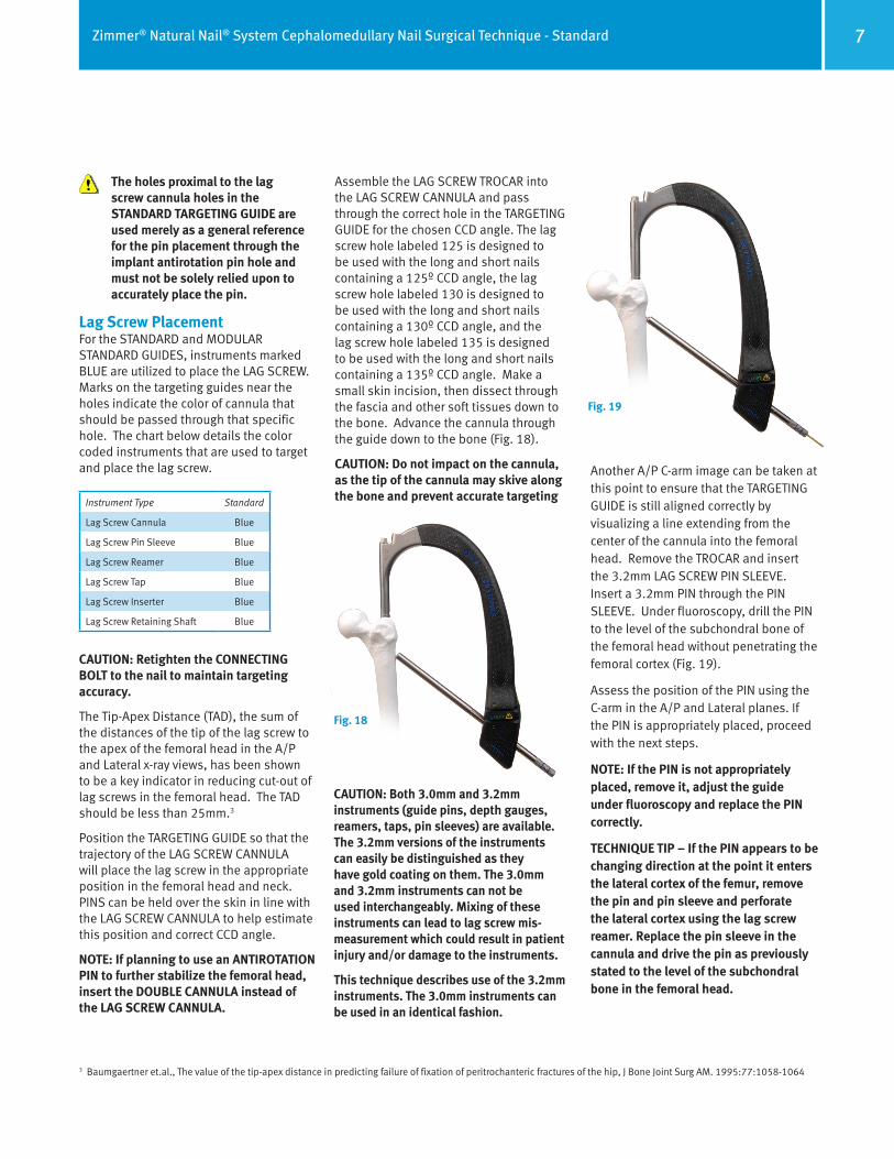
Assemble the LAG SCREW TROCAR into the LAG SCREW CANNULA and pass through the correct hole in the TARGETING GUIDE for the chosen CCD angle. The lag screw hole labeled 125 is designed to be used with the long and short nails containing a 125º CCD angle, the lag screw hole labeled 130 is designed to be used with the long and short nails containing a 130º CCD angle, and the lag screw hole labeled 135 is designed to be used with the long and short nails containinga135ºCCDangle.Makeasmallskinincision,thendissectthroughthe fascia and other soft tissues down to the bone. Advance the cannula through theguidedowntothebone(Fig.18).
CAUTION: Do not impact on the cannula, as the tip of the cannula may skive along the bone and prevent accurate targeting
Fig. 18
CAUTION: Both 3.0mm and 3.2mm instruments (guide pins, depth gauges, reamers, taps, pin sleeves) are available. The 3.2mm versions of the instruments can easily be distinguished as they have gold coating on them. The 3.0mm and 3.2mm instruments can not be used interchangeably. Mixing of these instruments can lead to lag screw mis-measurement which could result in patient injury and/or damage to the instruments.
This technique describes use of the 3.2mm instruments. The 3.0mm instruments can be used in an identical fashion.
Fig. 19
AnotherA/PC-armimagecanbetakenatthis point to ensure that the TARGETING GUIDE is still aligned correctly by visualizing a line extending from the center of the cannula into the femoral head. Remove the TROCAR and insert the 3.2mm LAG SCREW PIN SLEEVE. Insert a 3.2mm PIN through the PIN SLEEVE. Under fluoroscopy, drill the PIN to the level of the subchondral bone of the femoral head without penetrating the femoralcortex(Fig.19).
Assess the position of the PIN using the C-arm in the A/P and Lateral planes. If the PIN is appropriately placed, proceed with the next steps.
NOTE: If the PIN is not appropriately placed, remove it, adjust the guide under fluoroscopy and replace the PIN correctly.
TECHNIQUE TIP – If the PIN appears to be changing direction at the point it enters the lateral cortex of the femur, remove the pin and pin sleeve and perforate the lateral cortex using the lag screw reamer. Replace the pin sleeve in the cannula and drive the pin as previously stated to the level of the subchondral bone in the femoral head.
The holes proximal to the lag screw cannula holes in the STANDARD TARGETING GUIDE are used merely as a general reference for the pin placement through the implant antirotation pin hole and must not be solely relied upon to accurately place the pin.
3Baumgaertneret.al.,Thevalueofthetip-apexdistanceinpredictingfailureoffixationofperitrochantericfracturesofthehip,JBoneJointSurgAM.1995:77:1058-1064

Zimmer® Natural Nail® System Cephalomedullary Nail Surgical Technique - Standard8
Fig. 21
Fig. 22Remove the 3.2mm LAG SCREW PIN SLEEVE from The LAG SCREW CANNULA.
Slide the CANNULATED LAG SCREW DEPTH GAUGE over the 3.2mm PIN down tothebone(Fig.21).
Confirm that the depth gauge is touching the lateral cortex of the femur using fluoroscopy to accurately determine the length of lag screw to be used. The end of
Fig. 23
Fig. 24
Fig. 25
If it is desired to utilize an ANTIROTATION PIN to assist in stabilizing the femoral head during lag screw insertion, a 3.0mm ANTIROTATION PIN can be placed intothefemoralneckandheadusingaDOUBLECANNULA.UsethesmallersleeveoftheDOUBLECANNULAtoplacethis pin at this time. The pin is passed so that it does not penetrate the femoral cortexinthefemoralheadorneck(Fig.20). Place pin to appropriate depth beyond fracture site to provide stabilization.
NOTE: Place the 3.2mm PIN prior to the ANTIROTATION PIN to reduce mis-targeting. Position the ANTIROTATION PIN slightly proximal to the center-line of the femoral neck.
Alternatively, the pin can be placed using a freehand technique anterior to the nail andintothefemoralneckandhead.4, 5
NOTE: Insert 3.2mm pin anterior to the nail. Inserting them posterior to the nail may cause damage to the neurovascular structures.
the PIN in the depth gauge indicates the length of lag screw to be used.
SlidetheLAGSCREWSTOPASSEMBLYontotheLAGSCREWREAMER(Fig.22).Place the window in the stop over the number measured with the CANNULATED LAG SCREW DEPTHGAUGE(Fig. 23).Ifthemeasurement wasbetweenmarkingsonthe cannulated depth gauge, set the stop to the smaller number.
Prior to reaming, manually bend the ANTIROTATION PIN approximately 30o away from the path of the 3.2mm PIN. Attach the LAG SCREW REAMER to the drill. Ream over the PIN to the level of the subchondralbone(Fig.24).Whiledrilling,use the C-arm intermittently to verify positionofthereamerandtomakesurethat the PIN is not migrating through the femoral head. Remove the reamer. Push the end of the PIN while withdrawing the power tool.
The lag screw is self tapping. If preferred, tap a hole for the lag screw over the PIN. The stop can be used to indicate the appropriate depth gauge.
Select the appropriate length LAG SCREW based on previous measurements. The SCREW DEPTH GAUGE can also be used to verify the length of lag screw that should be used.
Attach the LAG SCREW to the LAG SCREW INSERTER using the LAG SCREW RETAINING SHAFTtofullysecurethescrewtotheinserter(Fig.25).
Fig. 20
4 AO Principles of Fracture Management, Thieme, 20005 Browner et.al., Skeletal Trauma Vol. 2, Basic Science, Management and Reconstruction, p.1929 – 1931, 2003
Zimmer® Natural Nail® System Cephalomedullary Nail Surgical Technique - Standard 9
Fig. 26
Fig. 27
Fig. 28
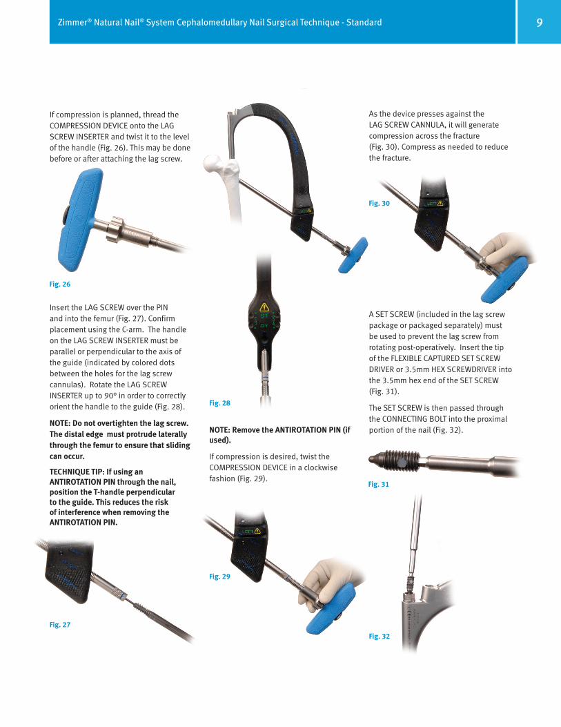
If compression is planned, thread the COMPRESSION DEVICE onto the LAG SCREW INSERTER and twist it to the level ofthehandle(Fig.26).Thismaybedonebefore or after attaching the lag screw.
Insert the LAG SCREW over the PIN andintothefemur(Fig.27).Confirmplacement using the C-arm. The handle on the LAG SCREW INSERTER must be parallel or perpendicular to the axis of the guide (indicated by colored dots between the holes for the lag screw cannulas). Rotate the LAG SCREW INSERTER up to 90° in order to correctly orientthehandletotheguide(Fig.28).
NOTE: Do not overtighten the lag screw. The distal edge must protrude laterally through the femur to ensure that sliding can occur.
TECHNIQUE TIP: If using an ANTIROTATION PIN through the nail, position the T-handle perpendicular to the guide. This reduces the risk of interference when removing the ANTIROTATION PIN.
Fig. 29
NOTE: Remove the ANTIROTATION PIN (if used).
If compression is desired, twist the COMPRESSIONDEVICEinaclockwisefashion(Fig.29).
Fig. 30
As the device presses against the LAG SCREW CANNULA, it will generate compression across the fracture (Fig.30).Compressasneededtoreducethe fracture.
Fig. 31
A SET SCREW (included in the lag screw packageorpackagedseparately)mustbe used to prevent the lag screw from rotating post-operatively. Insert the tip oftheFLEXIBLECAPTUREDSETSCREWDRIVERor3.5mmHEXSCREWDRIVERintothe 3.5mm hex end of the SET SCREW (Fig.31).
The SET SCREW is then passed through theCONNECTINGBOLTintotheproximalportionofthenail(Fig.32).
Fig. 32

Zimmer® Natural Nail® System Cephalomedullary Nail Surgical Technique - Standard10
NOTE: If using the FLEXIBLE CAPTURED SET SCREW DRIVER make sure that it is not used at an angle greater than 40˚. If it is used at an angle greater than 40˚, it may be damaged.
NOTE: Do not drive the set screw into the nail under power as damage to the set screw or the nail could result.
The SET SCREW should be tightened down into the groove in the lag screw. As noted above, the LAG SCREW INSERTER must be positioned so that the handle on the inserter is parallel or perpendicular to the colored dots on the TARGETING GUIDE in order for the SET SCREW and LAG SCREW grooves to engage properly. To verify engagement, attempt to twist the LAG SCREW INSERTER. If it cannot be rotated using a reasonable amount of force, the construct is in the correct position. If rotation is possible, adjust the position of the LAG SCREW (rotate slightly) so that the set screw can enter the grooveintheLAGSCREW(Fig.33).
Fig. 33
NOTE: To achieve sliding, tighten the SET SCREW and then rotate the FLEXIBLE CAPTURED SET SCREW DRIVER counterclockwise one quarter turn. Do not unscrew the SET SCREW more than one quarter turn. Make sure that the SET SCREW is still engaged in the groove by checking that it is still not possible to turn the LAG SCREW with the LAG SCREW INSERTER.
Disengage the LAG SCREW INSERTER fromtheLAGSCREW.A3.5mmHEXSCREWDRIVER may be used to disengage theLAGSCREWRETAININGSHAFTfromtheLAG SCREW.
TECHNIQUE TIP: The LAG SCREW CANNULA can be left in place to aid in stabilizing the construct during distal screw placement in the short nails, if desired (Fig. 34). Remove the FLEXIBLE CAPTURED SET SCREW DRIVER and set aside.
Distal Targeting For Short NailsColor coded instruments are also used fordistaltargetingofshortnails.FortheSTANDARD TARGETING GUIDE, instruments markedGREENareutilizedtoplacethedistal screws. The chart below details the color coded instruments that are used for distal targeting and distal screw placement.
The STANDARD TARGETING GUIDE is designed to target the distal static (ST) and dynamic (DY) holes in SHORT nails. As the guide is designed to work with both left and right ST and
DY holes, care must be taken to ensure that the correct targeting holes (left or right) are used for drilling and screw placement. At this point in the surgery, with the guide oriented horizontally and the nail in place, the correct holes are on the top (anterior) side of the guide. A YELLOW CAUTION SYMBOL is engraved on the face of the guide near the ST/DY holes to remind the surgeon to take note of the placement of the screw. Additionally, the words “LEFT” and “RIGHT” are embossed in green on the appropriate side of the guide where the SCREW CANNULAS should be placed to insert these screws.
The MODULAR STANDARD TARGETING GUIDE can not be used to distal target the short nails.
Assemble the TROCAR to the 8.0mm CANNULA. Pass the CANNULA through the appropriate hole in the TARGETING GUIDE to target the distal hole or slot. The hole is labeled ST is for the Static Hole. The hole labeled DY is for the Dynamic Slot.
After pressing the tip of the TROCAR and CANNULA againsttheskin,makeasmallincisionatthatpointthroughtheskinandfascia lata. Spread the soft tissue down to the bone. Advance the CANNULA down to the bone.
CAUTION: Do not impact on the CANNULA or TROCAR, as the tip of the cannula may skive along the bone and prevent accurate targeting.
Remove the TROCAR (if used) and insert the 4,3mm DRILL SLEEVE into the CANNULA.
Utilizethe4.3mmDRILLBITtodrillthroughboth cortices of bone. The depth of the hole can be measured using calibrations on the DRILLBIT.Anotheroptionistoremovethedrill bit and the drill sleeve and then use the SCREW DEPTH GAUGE to measure the depth of the hole.
CAUTION: In cases where hard cortical bone is encountered, or at the surgeon’s preference, a 5.0mm TAP (00-2490-048-50) can be used to ease insertion of the screws.
Fig. 34
Instrument Type Standard
8.0mm Screw Cannula Green
4.3mm Drill Sleeve Green–Red
4.3mmDrillBit Green–Red
Screwdriver Green
Screw Depth Gauge Green

Zimmer® Natural Nail® System Cephalomedullary Nail Surgical Technique - Standard 11
Fig. 34
The nail utilizes a 5.0mm screw distally. Thescrewpackagesarelabeledwiththe color RED. The distal hole and slot in the nail allows for standard or fixed anglelocking.ToachieveSTANDARDLOCKING, choose a PARTIALLY THREADED 5.0mmSCREW.ToachieveaFIXEDANGLEconstruct,chooseaFIXEDANGLE5.0mmSCREW(Fig35),applicableforlongnails only). In SHORT nails, either screw type will result in a STANDARD LOCKING construct.
Choose the appropriate length screw based ontheDEPTHGAUGEorDRILLBITreading.Usethe3.5mmHEXSCREWDRIVERtoplacethe screw bicortically through the bone.
If using the CAPTURED SCREWDRIVER, place the appropriate screw on the 3.5mm HEXandtightenthescrewtotheCAPTURED SCREWDRIVERbyturningtheknobnexttothehandleclockwise.
CAUTION: If using the CAPTURED SCREW DRIVER, do not torque the CAPTURED SCREWDRIVER beyond the calibration line next to the handle.
CAUTION: Do not drive the screws into the bone under power, as damage to the bone, screws and nail could result.
Remove the screwdriver and cannula. If desired, repeat these steps to place another screw in the other hole or slot. If not previously done, remove the LAG SCREW CANNULA.
Freehand Technique for Long NailsInserttheFREEHAND4.3mmDRILLBIT(RED) into the DISTAL TARGETING DEVICE. FingertightentheSETSCREW.Position
* It is the responsibility of the surgeon to determine what is the most suitable postoperative
care depending on each patient’s health condition.
the C-arm in order to get a lateral view of the distal femur. Adjust the angle of the C-arm so that the hole through the nail appears as aperfectcircleonthemonitor.BringthetipofthedrillbittotheskinandusetheC-armto center it over the hole that you desire to placeascrewthrough.Makeastabwoundat this point and dissect down to the bone. Place the tip of the drill bit against the bone. Verify that the tip of the drill bit is in the center of the hole. Align the drill bit with the C-arm beam. Tap the drill bit into the bone using the MALLET.
Remove the DISTAL TARGETING DEVICE. Slide theFREEHANDTISSUEPROTECTIONSLEEVEovertheDRILLBIT.AttachtheDRILLtotheFREEHAND4.3mmDRILLBITandadvancethe drill bit through the bone. Verify that the drill bit has gone through the hole in the nail.
Remove the drill bit. Measure the depth of theholeusingtheFREEHANDSCREWDEPTHGAUGE. Insert the appropriate length screw using the screwdriver.
If using the CAPTURED SCREWDRIVER, place theappropriatescrewonthe3.5mmHEXand tighten the screw to the CAPTURED SCREWDRIVERbyturningtheknobnexttothehandleclockwise(Fig.36).
CAUTION: If using the CAPTURED SCREW DRIVER, do not torque the CAPTURED SCREWDRIVER beyond the calibration line next to the handle.
CAUTION: Do not drive the screws into the bone under power, as damage to the bone, screws and nail could result.
Repeat these steps to insert additional distal screws.
Final Implant PlacementObserve the depth of the nail in the proximal femur. Ridges at 5 and 10mm from the end of the targeting guide barrel indicate nail depth.
It is recommended to use a NAIL CAP to close the proximal part of the nail to prevent bone ingrowth.
Place a 2.0mm GUIDE PIN through the CONNECTINGBOLTandintotheproximalportion of the NAIL. Loosen and remove the CONNECTINGBOLTfromthenailtakingcareto leave the 2.0mm GUIDE PIN in place. If a NAIL CAP will not be used, do not introduce the 2.0mm GUIDE PIN.
TECHNIQUE NOTE: The 0mm height NAIL CAP can be placed through the TARGETING GUIDE following removal of the CONNECTING BOLT. Other NAIL CAPS cannot be placed until the TARGETING GUIDE is also removed.
Choose the appropriate height of NAIL CAP. Secure the selected NAIL CAP to the NAIL CAP INSERTER using the NAIL CAP RETAININGSHAFT(Fig.37).
Place the NAIL CAP over the 2.0mm GUIDE WIRE and thread it into the top of the NAIL. Using the C-arm, verify that the cap is completely seated in the top of the nail.
Disengage the NAIL CAP INSERTER from the NAIL CAP. Remove the 2.0mm GUIDE PIN.
Close all wounds and apply the appropriate dressings.
Fig. 37Fig. 36
Fig. 35
Zimmer® Natural Nail® System Cephalomedullary Nail Surgical Technique - Standard12
Postoperative CareEarlyrangeofmotionexercisesofthekneeandankleareencouraged.Allowtoe-touchweight bearing to progress to full weight bearing as fracture callus increases on the x-ray films.*
Nail ExtractionUse the C-arm to locate any distal screws. Removethescrewsusinga3.5mmHEXSCREWDRIVER. Remove the NAIL CAP (if one was inserted) with a 5.0mm HEXSCREWDRIVER.Usea3.5mmHEXSCREWDRIVER to remove the set screw. Expose the lag screw and use the LAG SCREW INSERTER to remove it.
NOTE: To remove the lag screw it is not necessary that the set screw is completely removed. Turn the set screw two turns backwards and make sure that the set screw is still engaged in the threads of the nail.
NOTE: It is recommended to use the LAG SCREW CANNULA as guidance for the LAG SCREW INSERTER while removing the lag screw. Assemble the LAG SCREW INSERTER through the LAG SCREW CANNULA into the lag screw. Use the compression device to push the LAG SCREW CANNULA to the bone. Make sure the LAG SCREW INSERTER is fully seated. Hand tighten the LAG SCREW INSERTER with the 3.5mm HEX SCREWDRIVER.
To remove the nail, slide a 3.0mm x 100cm GUIDE WIRE through the nail. Insert the CEPHALOMEDULLARY CANNULATED EXTRACTIONADAPTERoverthewireintothe top of the nail. Tighten the adapter to the nail. Attach a SLAPHAMMER or other impactiondeviceandimpacttobackout the nail. The nail should move with each impaction. Periodically retighten the adapter and/or SLAPHAMMER during extraction as needed. The nail may rotate as it passes through the canal during extraction.

Zimmer® Natural Nail® System Cephalomedullary Nail Surgical Technique - Standard 13
Cephalomedullary Long Nail Details
4o Proximal Lateralization Angle
10, 11.5, 13mm shaft diameters
SpiralFlutes
45 to 50mm from tip
34 to 39mm from tip
17 to 29mm from tip (Dynamic Slot)
Anterior bevel on tip7 to 12mm from tip
15.5mm Proximal Head
58mm Proximal Body Length
1275mm AnteriorBowRadiusLengths 30 through 34cm
1400mm AnteriorBowRadiusLengths 36 through 40cm
1525mm AnteriorBowRadiusLengths 42 through 48cm
Lag Screw
10.5mm Diameter
6.6mm Minor Diameter
10.2mm Drill
2.8mm Tip Length
5.0mm Screw
8mm Diameter Head
3.8mm Head Height
4.3mm Minor Diameter
4.3mm Drill
2.0mm Tip Length
35 to 39mm from tip (3.0mm Pin)
42 to 54mm from tip (10.5mm Lag Screw)
Blue Ring
15o Anteversion
125o / 130o/ 135o CCD Angle

Zimmer® Natural Nail® System Cephalomedullary Nail Surgical Technique - Standard14
Cephalomedullary Short Nail Details
4o Proximal Lateralization Angle
10, 11.5, 13, 14.5mm shaft diameters
60 to65mm from tip
43 to 55mm from tip (Dynamic Slot)
Clothespin tip (for nails 11.5mm in diameter and larger)
15.5mm Proximal Head
58mm Proximal Body Length
1275mm AnteriorBowRadius
35 to 39mm from tip (3.0mm Pin)
42 to 54mm from tip (10.5mm Lag Screw)
Lag Screw
10.5mm Diameter
6.6mm Minor Diameter
10.2mm Drill
2.8mm Tip Length
5.0mm Screw
8mm Diameter Head
3.8mm Head Height
4.3mm Minor Diameter
4.3mm Drill
2.0mm Tip Length
BlueRing
5.0mm Screws
15o Anteversion
NOTE: There is no locking tab (StabiliZe Technology) for the Cephalomedullary Short Nails.
125o / 130o/ 135o CCD Angle

Zimmer® Natural Nail® System Cephalomedullary Nail Surgical Technique - Standard 15
Item Number Product Description
47-2493-300-10CephalomedullaryLongNail10mmX30cm125CCDRightTi-6Al-4V Alloy
47-2493-301-10CephalomedullaryLongNail10mmX30cm125CCDLeftTi-6Al-4V Alloy
47-2493-302-10CephalomedullaryLongNail10mmX30cm130CCDRightTi-6Al-4V Alloy
47-2493-303-10CephalomedullaryLongNail10mmX30cm130CCDLeftTi-6Al-4V Alloy
47-2493-304-10CephalomedullaryLongNail10mmX30cm135CCDRightTi-6Al-4V Alloy
47-2493-305-10CephalomedullaryLongNail10mmX30cm135CCDLeftTi-6Al-4V Alloy
47-2493-320-10CephalomedullaryLongNail10mmX32cm125CCDRightTi-6Al-4V Alloy
47-2493-321-10CephalomedullaryLongNail10mmX32cm125CCDLeftTi-6Al-4V Alloy
47-2493-322-10CephalomedullaryLongNail10mmX32cm130CCDRightTi-6Al-4V Alloy
47-2493-323-10CephalomedullaryLongNail10mmX32cm130CCDLeftTi-6Al-4V Alloy
47-2493-324-10CephalomedullaryLongNail10mmX32cm135CCDRightTi-6Al-4V Alloy
47-2493-325-10CephalomedullaryLongNail10mmX32cm135CCDLeftTi-6Al-4V Alloy
47-2493-340-10CephalomedullaryLongNail10mmX34cm125CCDRightTi-6Al-4V Alloy
47-2493-341-10CephalomedullaryLongNail10mmX34cm125CCDLeftTi-6Al-4V Alloy
47-2493-342-10CephalomedullaryLongNail10mmX34cm130CCDRightTi-6Al-4V Alloy
47-2493-343-10CephalomedullaryLongNail10mmX34cm130CCDLeftTi-6Al-4V Alloy
47-2493-344-10CephalomedullaryLongNail10mmX34cm135CCDRightTi-6Al-4V Alloy
47-2493-345-10CephalomedullaryLongNail10mmX34cm135CCDLeftTi-6Al-4V Alloy
47-2493-360-10CephalomedullaryLongNail10mmX36cm125CCDRightTi-6Al-4V Alloy
47-2493-361-10CephalomedullaryLongNail10mmX36cm125CCDLeftTi-6Al-4V Alloy
47-2493-362-10CephalomedullaryLongNail10mmX36cm130CCDRightTi-6Al-4V Alloy
47-2493-363-10CephalomedullaryLongNail10mmX36cm130CCDLeftTi-6Al-4V Alloy
47-2493-364-10CephalomedullaryLongNail10mmX36cm135CCDRightTi-6Al-4V Alloy
47-2493-365-10CephalomedullaryLongNail10mmX36cm135CCDLeftTi-6Al-4V Alloy
47-2493-380-10CephalomedullaryLongNail10mmX38cm125CCDRightTi-6Al-4V Alloy
47-2493-381-10CephalomedullaryLongNail10mmX38cm125CCDLeftTi-6Al-4V Alloy
47-2493-382-10CephalomedullaryLongNail10mmX38cm130CCDRightTi-6Al-4V Alloy
47-2493-383-10CephalomedullaryLongNail10mmX38cm130CCDLeftTi-6Al-4V Alloy
47-2493-384-10CephalomedullaryLongNail10mmX38cm135CCDRightTi-6Al-4V Alloy
Cephalomedullary Short Nails
Product Information
Item Number Product Description
47-2493-210-10CephalomedullaryShortNail10mmX21.5cm125CCDRight Ti-6Al-4V Alloy
47-2493-211-10CephalomedullaryShortNail10mmX21.5cm125CCDLeft Ti-6Al-4V Alloy
47-2493-212-10CephalomedullaryShortNail10mmX21.5cm130CCDRight Ti-6Al-4V Alloy
47-2493-213-10CephalomedullaryShortNail10mmX21.5cm130CCDLeft Ti-6Al-4V Alloy
47-2493-214-10CephalomedullaryShortNail10mmX21.5cm135CCDRight Ti-6Al-4V Alloy
47-2493-215-10CephalomedullaryShortNail10mmX21.5cm135CCDLeft Ti-6Al-4V Alloy
47-2493-210-11CephalomedullaryShortNail11.5mmX21.5cm125CCDRight Ti-6Al-4V Alloy
47-2493-211-11CephalomedullaryShortNail11.5mmX21.5cm125CCDLeft Ti-6Al-4V Alloy
47-2493-212-11CephalomedullaryShortNail11.5mmX21.5cm130CCDRight Ti-6Al-4V Alloy
47-2493-213-11CephalomedullaryShortNail11.5mmX21.5cm130CCDLeft Ti-6Al-4V Alloy
47-2493-214-11CephalomedullaryShortNail11.5mmX21.5cm135CCDRight Ti-6Al-4V Alloy
47-2493-215-11CephalomedullaryShortNail11.5mmX21.5cm135CCDLeft Ti-6Al-4V Alloy
47-2493-210-13CephalomedullaryShortNail13mmX21.5cm125CCDRight Ti-6Al-4V Alloy
47-2493-211-13CephalomedullaryShortNail13mmX21.5cm125CCDLeft Ti-6Al-4V Alloy
47-2493-212-13CephalomedullaryShortNail13mmX21.5cm130CCDRight Ti-6Al-4V Alloy
47-2493-213-13CephalomedullaryShortNail13mmX21.5cm130CCDLeft Ti-6Al-4V Alloy
47-2493-214-13CephalomedullaryShortNail13mmX21.5cm135CCDRight Ti-6Al-4V Alloy
47-2493-215-13CephalomedullaryShortNail13mmX21.5cm135CCDLeft Ti-6Al-4V Alloy
47-2493-210-14CephalomedullaryShortNail14.5mmX21.5cm125CCDRight Ti-6Al-4V Alloy
47-2493-211-14CephalomedullaryShortNail14.5mmX21.5cm125CCDLeft Ti-6Al-4V Alloy
47-2493-212-14CephalomedullaryShortNail14.5mmX21.5cm130CCDRight Ti-6Al-4V Alloy
47-2493-213-14CephalomedullaryShortNail14.5mmX21.5cm130CCDLeft Ti-6Al-4V Alloy
47-2493-214-14CephalomedullaryShortNail14.5mmX21.5cm135CCDRight Ti-6Al-4V Alloy
47-2493-215-14CephalomedullaryShortNail14.5mmX21.5cm135CCDLeft Ti-6Al-4V Alloy
Cephalomedullary Long Nails

Zimmer® Natural Nail® System Cephalomedullary Nail Surgical Technique - Standard16
47-2493-385-10CephalomedullaryLongNail10mmX38cm135CCDLeftTi-6Al-4V Alloy
47-2493-400-10CephalomedullaryLongNail10mmX40cm125CCDRightTi-6Al-4V Alloy
47-2493-401-10CephalomedullaryLongNail10mmX40cm125CCDLeftTi-6Al-4V Alloy
47-2493-402-10CephalomedullaryLongNail10mmX40cm130CCDRightTi-6Al-4V Alloy
47-2493-403-10CephalomedullaryLongNail10mmX40cm130CCDLeftTi-6Al-4V Alloy
47-2493-404-10CephalomedullaryLongNail10mmX40cm135CCDRightTi-6Al-4V Alloy
47-2493-405-10CephalomedullaryLongNail10mmX40cm135CCDLeftTi-6Al-4V Alloy
47-2493-420-10CephalomedullaryLongNail10mmX42cm125CCDRightTi-6Al-4V Alloy
47-2493-421-10CephalomedullaryLongNail10mmX42cm125CCDLeftTi-6Al-4V Alloy
47-2493-422-10CephalomedullaryLongNail10mmX42cm130CCDRightTi-6Al-4V Alloy
47-2493-423-10CephalomedullaryLongNail10mmX42cm130CCDLeftTi-6Al-4V Alloy
47-2493-424-10CephalomedullaryLongNail10mmX42cm135CCDRightTi-6Al-4V Alloy
47-2493-425-10CephalomedullaryLongNail10mmX42cm135CCDLeftTi-6Al-4V Alloy
47-2493-440-10CephalomedullaryLongNail10mmX44cm125CCDRightTi-6Al-4V Alloy
47-2493-441-10CephalomedullaryLongNail10mmX44cm125CCDLeftTi-6Al-4V Alloy
47-2493-442-10CephalomedullaryLongNail10mmX44cm130CCDRightTi-6Al-4V Alloy
47-2493-443-10CephalomedullaryLongNail10mmX44cm130CCDLeftTi-6Al-4V Alloy
47-2493-444-10CephalomedullaryLongNail10mmX44cm135CCDRightTi-6Al-4V Alloy
47-2493-445-10CephalomedullaryLongNail10mmX44cm135CCDLeftTi-6Al-4V Alloy
47-2493-460-10CephalomedullaryLongNail10mmX46cm125CCDRightTi-6Al-4V Alloy
47-2493-461-10CephalomedullaryLongNail10mmX46cm125CCDLeftTi-6Al-4V Alloy
47-2493-462-10CephalomedullaryLongNail10mmX46cm130CCDRightTi-6Al-4V Alloy
47-2493-463-10CephalomedullaryLongNail10mmX46cm130CCDLeftTi-6Al-4V Alloy
47-2493-464-10CephalomedullaryLongNail10mmX46cm135CCDRightTi-6Al-4V Alloy
47-2493-465-10CephalomedullaryLongNail10mmX46cm135CCDLeftTi-6Al-4V Alloy
47-2493-480-10CephalomedullaryLongNail10mmX48cm125CCDRightTi-6Al-4V Alloy
47-2493-481-10CephalomedullaryLongNail10mmX48cm125CCDLeftTi-6Al-4V Alloy
47-2493-482-10CephalomedullaryLongNail10mmX48cm130CCDRightTi-6Al-4V Alloy
47-2493-483-10CephalomedullaryLongNail10mmX48cm130CCDLeftTi-6Al-4V Alloy
47-2493-484-10CephalomedullaryLongNail10mmX48cm135CCDRightTi-6Al-4V Alloy
47-2493-485-10CephalomedullaryLongNail10mmX48cm135CCDLeftTi-6Al-4V Alloy
47-2493-300-11CephalomedullaryLongNail11.5mmX30cm125CCDRight Ti-6Al-4V Alloy
47-2493-301-11CephalomedullaryLongNail11.5mmX30cm125CCDLeft Ti-6Al-4V Alloy
47-2493-302-11CephalomedullaryLongNail11.5mmX30cm130CCDRight Ti-6Al-4V Alloy
47-2493-303-11CephalomedullaryLongNail11.5mmX30cm130CCDLeft Ti-6Al-4V Alloy
47-2493-304-11CephalomedullaryLongNail11.5mmX30cm135CCDRight Ti-6Al-4V Alloy
47-2493-305-11CephalomedullaryLongNail11.5mmX30cm135CCDLeft Ti-6Al-4V Alloy
47-2493-320-11CephalomedullaryLongNail11.5mmX32cm125CCDRight Ti-6Al-4V Alloy
47-2493-321-11CephalomedullaryLongNail11.5mmX32cm125CCDLeft Ti-6Al-4V Alloy
47-2493-322-11CephalomedullaryLongNail11.5mmX32cm130CCDRight Ti-6Al-4V Alloy
47-2493-323-11CephalomedullaryLongNail11.5mmX32cm130CCDLeft Ti-6Al-4V Alloy
47-2493-324-11CephalomedullaryLongNail11.5mmX32cm135CCDRight Ti-6Al-4V Alloy
47-2493-325-11CephalomedullaryLongNail11.5mmX32cm135CCDLeft Ti-6Al-4V Alloy
47-2493-340-11CephalomedullaryLongNail11.5mmX34cm125CCDRight Ti-6Al-4V Alloy
47-2493-341-11CephalomedullaryLongNail11.5mmX34cm125CCDLeft Ti-6Al-4V Alloy
47-2493-342-11CephalomedullaryLongNail11.5mmX34cm130CCDRight Ti-6Al-4V Alloy
47-2493-343-11CephalomedullaryLongNail11.5mmX34cm130CCDLeft Ti-6Al-4V Alloy
47-2493-344-11CephalomedullaryLongNail11.5mmX34cm135CCDRight Ti-6Al-4V Alloy
47-2493-345-11CephalomedullaryLongNail11.5mmX34cm135CCDLeft Ti-6Al-4V Alloy
47-2493-360-11CephalomedullaryLongNail11.5mmX36cm125CCDRight Ti-6Al-4V Alloy
47-2493-361-11CephalomedullaryLongNail11.5mmX36cm125CCDLeft Ti-6Al-4V Alloy
47-2493-362-11CephalomedullaryLongNail11.5mmX36cm130CCDRight Ti-6Al-4V Alloy
47-2493-363-11CephalomedullaryLongNail11.5mmX36cm130CCDLeft Ti-6Al-4V Alloy
47-2493-364-11CephalomedullaryLongNail11.5mmX36cm135CCDRight Ti-6Al-4V Alloy
47-2493-365-11CephalomedullaryLongNail11.5mmX36cm135CCDLeft Ti-6Al-4V Alloy
47-2493-380-11CephalomedullaryLongNail11.5mmX38cm125CCDRight Ti-6Al-4V Alloy
47-2493-381-11CephalomedullaryLongNail11.5mmX38cm125CCDLeft Ti-6Al-4V Alloy
47-2493-382-11CephalomedullaryLongNail11.5mmX38cm130CCDRight Ti-6Al-4V Alloy
47-2493-383-11CephalomedullaryLongNail11.5mmX38cm130CCDLeft Ti-6Al-4V Alloy
47-2493-384-11CephalomedullaryLongNail11.5mmX38cm135CCDRight Ti-6Al-4V Alloy

Zimmer® Natural Nail® System Cephalomedullary Nail Surgical Technique - Standard 17
47-2493-485-11CephalomedullaryLongNail11.5mmX48cm135CCDLeft Ti-6Al-4V Alloy
47-2493-300-13CephalomedullaryLongNail13mmX30cm125CCDRightTi-6Al-4V Alloy
47-2493-301-13CephalomedullaryLongNail13mmX30cm125CCDLeftTi-6Al-4V Alloy
47-2493-302-13CephalomedullaryLongNail13mmX30cm130CCDRightTi-6Al-4V Alloy
47-2493-303-13CephalomedullaryLongNail13mmX30cm130CCDLeftTi-6Al-4V Alloy
47-2493-304-13CephalomedullaryLongNail13mmX30cm135CCDRightTi-6Al-4V Alloy
47-2493-305-13CephalomedullaryLongNail13mmX30cm135CCDLeftTi-6Al-4V Alloy
47-2493-320-13CephalomedullaryLongNail13mmX32cm125CCDRightTi-6Al-4V Alloy
47-2493-321-13CephalomedullaryLongNail13mmX32cm125CCDLeftTi-6Al-4V Alloy
47-2493-322-13CephalomedullaryLongNail13mmX32cm130CCDRightTi-6Al-4V Alloy
47-2493-323-13CephalomedullaryLongNail13mmX32cm130CCDLeftTi-6Al-4V Alloy
47-2493-324-13CephalomedullaryLongNail13mmX32cm135CCDRightTi-6Al-4V Alloy
47-2493-325-13CephalomedullaryLongNail13mmX32cm135CCDLeftTi-6Al-4V Alloy
47-2493-340-13CephalomedullaryLongNail13mmX34cm125CCDRightTi-6Al-4V Alloy
47-2493-341-13CephalomedullaryLongNail13mmX34cm125CCDLeftTi-6Al-4V Alloy
47-2493-342-13CephalomedullaryLongNail13mmX34cm130CCDRightTi-6Al-4V Alloy
47-2493-343-13CephalomedullaryLongNail13mmX34cm130CCDLeftTi-6Al-4V Alloy
47-2493-344-13CephalomedullaryLongNail13mmX34cm135CCDRightTi-6Al-4V Alloy
47-2493-345-13CephalomedullaryLongNail13mmX34cm135CCDLeftTi-6Al-4V Alloy
47-2493-360-13CephalomedullaryLongNail13mmX36cm125CCDRightTi-6Al-4V Alloy
47-2493-361-13CephalomedullaryLongNail13mmX36cm125CCDLeftTi-6Al-4V Alloy
47-2493-362-13CephalomedullaryLongNail13mmX36cm130CCDRightTi-6Al-4V Alloy
47-2493-363-13CephalomedullaryLongNail13mmX36cm130CCDLeftTi-6Al-4V Alloy
47-2493-364-13CephalomedullaryLongNail13mmX36cm135CCDRightTi-6Al-4V Alloy
47-2493-365-13CephalomedullaryLongNail13mmX36cm135CCDLeftTi-6Al-4V Alloy
47-2493-380-13CephalomedullaryLongNail13mmX38cm125CCDRightTi-6Al-4V Alloy
47-2493-381-13CephalomedullaryLongNail13mmX38cm125CCDLeftTi-6Al-4V Alloy
47-2493-382-13CephalomedullaryLongNail13mmX38cm130CCDRightTi-6Al-4V Alloy
47-2493-383-13CephalomedullaryLongNail13mmX38cm130CCDLeftTi-6Al-4V Alloy
47-2493-384-13CephalomedullaryLongNail13mmX38cm135CCDRightTi-6Al-4V Alloy
47-2493-385-11CephalomedullaryLongNail11.5mmX38cm135CCDLeft Ti-6Al-4V Alloy
47-2493-400-11CephalomedullaryLongNail11.5mmX40cm125CCDRight Ti-6Al-4V Alloy
47-2493-401-11CephalomedullaryLongNail11.5mmX40cm125CCDLeft Ti-6Al-4V Alloy
47-2493-402-11CephalomedullaryLongNail11.5mmX40cm130CCDRight Ti-6Al-4V Alloy
47-2493-403-11CephalomedullaryLongNail11.5mmX40cm130CCDLeft Ti-6Al-4V Alloy
47-2493-404-11CephalomedullaryLongNail11.5mmX40cm135CCDRight Ti-6Al-4V Alloy
47-2493-405-11CephalomedullaryLongNail11.5mmX40cm135CCDLeft Ti-6Al-4V Alloy
47-2493-420-11CephalomedullaryLongNail11.5mmX42cm125CCDRight Ti-6Al-4V Alloy
47-2493-421-11CephalomedullaryLongNail11.5mmX42cm125CCDLeft Ti-6Al-4V Alloy
47-2493-422-11CephalomedullaryLongNail11.5mmX42cm130CCDRight Ti-6Al-4V Alloy
47-2493-423-11CephalomedullaryLongNail11.5mmX42cm130CCDLeft Ti-6Al-4V Alloy
47-2493-424-11CephalomedullaryLongNail11.5mmX42cm135CCDRight Ti-6Al-4V Alloy
47-2493-425-11CephalomedullaryLongNail11.5mmX42cm135CCDLeft Ti-6Al-4V Alloy
47-2493-440-11CephalomedullaryLongNail11.5mmX44cm125CCDRight Ti-6Al-4V Alloy
47-2493-441-11CephalomedullaryLongNail11.5mmX44cm125CCDLeft Ti-6Al-4V Alloy
47-2493-442-11CephalomedullaryLongNail11.5mmX44cm130CCDRight Ti-6Al-4V Alloy
47-2493-443-11CephalomedullaryLongNail11.5mmX44cm130CCDLeft Ti-6Al-4V Alloy
47-2493-444-11CephalomedullaryLongNail11.5mmX44cm135CCDRight Ti-6Al-4V Alloy
47-2493-445-11CephalomedullaryLongNail11.5mmX44cm135CCDLeft Ti-6Al-4V Alloy
47-2493-460-11CephalomedullaryLongNail11.5mmX46cm125CCDRight Ti-6Al-4V Alloy
47-2493-461-11CephalomedullaryLongNail11.5mmX46cm125CCDLeft Ti-6Al-4V Alloy
47-2493-462-11CephalomedullaryLongNail11.5mmX46cm130CCDRight Ti-6Al-4V Alloy
47-2493-463-11CephalomedullaryLongNail11.5mmX46cm130CCDLeft Ti-6Al-4V Alloy
47-2493-464-11CephalomedullaryLongNail11.5mmX46cm135CCDRight Ti-6Al-4V Alloy
47-2493-465-11CephalomedullaryLongNail11.5mmX46cm135CCDLeft Ti-6Al-4V Alloy
47-2493-480-11CephalomedullaryLongNail11.5mmX48cm125CCDRight Ti-6Al-4V Alloy
47-2493-481-11CephalomedullaryLongNail11.5mmX48cm125CCDLeft Ti-6Al-4V Alloy
47-2493-482-11CephalomedullaryLongNail11.5mmX48cm130CCDRight Ti-6Al-4V Alloy
47-2493-483-11CephalomedullaryLongNail11.5mmX48cm130CCDLeft Ti-6Al-4V Alloy
47-2493-484-11CephalomedullaryLongNail11.5mmX48cm135CCDRight Ti-6Al-4V Alloy

Zimmer® Natural Nail® System Cephalomedullary Nail Surgical Technique - Standard18
47-2493-385-13CephalomedullaryLongNail13mmX38cm135CCDLeftTi-6Al-4V Alloy
47-2493-400-13CephalomedullaryLongNail13mmX40cm125CCDRightTi-6Al-4V Alloy
47-2493-401-13CephalomedullaryLongNail13mmX40cm125CCDLeftTi-6Al-4V Alloy
47-2493-402-13CephalomedullaryLongNail13mmX40cm130CCDRightTi-6Al-4V Alloy
47-2493-403-13CephalomedullaryLongNail13mmX40cm130CCDLeftTi-6Al-4V Alloy
47-2493-404-13CephalomedullaryLongNail13mmX40cm135CCDRightTi-6Al-4V Alloy
47-2493-405-13CephalomedullaryLongNail13mmX40cm135CCDLeftTi-6Al-4V Alloy
47-2493-420-13CephalomedullaryLongNail13mmX42cm125CCDRightTi-6Al-4V Alloy
47-2493-421-13CephalomedullaryLongNail13mmX42cm125CCDLeftTi-6Al-4V Alloy
47-2493-422-13CephalomedullaryLongNail13mmX42cm130CCDRightTi-6Al-4V Alloy
47-2493-423-13CephalomedullaryLongNail13mmX42cm130CCDLeftTi-6Al-4V Alloy
47-2493-424-13CephalomedullaryLongNail13mmX42cm135CCDRightTi-6Al-4V Alloy
47-2493-425-13CephalomedullaryLongNail13mmX42cm135CCDLeftTi-6Al-4V Alloy
47-2493-440-13CephalomedullaryLongNail13mmX44cm125CCDRightTi-6Al-4V Alloy
47-2493-441-13CephalomedullaryLongNail13mmX44cm125CCDLeftTi-6Al-4V Alloy
47-2493-442-13CephalomedullaryLongNail13mmX44cm130CCDRightTi-6Al-4V Alloy
47-2493-443-13CephalomedullaryLongNail13mmX44cm130CCDLeftTi-6Al-4V Alloy
47-2493-444-13CephalomedullaryLongNail13mmX44cm135CCDRightTi-6Al-4V Alloy
47-2493-445-13CephalomedullaryLongNail13mmX44cm135CCDLeftTi-6Al-4V Alloy
47-2493-460-13CephalomedullaryLongNail13mmX46cm125CCDRightTi-6Al-4V Alloy
47-2493-461-13CephalomedullaryLongNail13mmX46cm125CCDLeftTi-6Al-4V Alloy
47-2493-462-13CephalomedullaryLongNail13mmX46cm130CCDRightTi-6Al-4V Alloy
47-2493-463-13CephalomedullaryLongNail13mmX46cm130CCDLeftTi-6Al-4V Alloy
47-2493-464-13CephalomedullaryLongNail13mmX46cm135CCDRightTi-6Al-4V Alloy
47-2493-465-13CephalomedullaryLongNail13mmX46cm135CCDLeftTi-6Al-4V Alloy
47-2493-480-13CephalomedullaryLongNail13mmX48cm125CCDRightTi-6Al-4V Alloy
47-2493-481-13CephalomedullaryLongNail13mmX48cm125CCDLeftTi-6Al-4V Alloy
47-2493-482-13CephalomedullaryLongNail13mmX48cm130CCDRightTi-6Al-4V Alloy
47-2493-483-13CephalomedullaryLongNail13mmX48cm130CCDLeftTi-6Al-4V Alloy
47-2493-484-13CephalomedullaryLongNail13mmX48cm135CCDRightTi-6Al-4V Alloy
47-2493-485-13CephalomedullaryLongNail13mmX48cm135CCDLeftTi-6Al-4V Alloy
Item Number Product Description
47-2485-070-10 10.5mm Lag Screw 70mm Length Ti-6Al-4V Alloy
47-2485-075-10 10.5mm Lag Screw 75mm Length Ti-6Al-4V Alloy
47-2485-080-10 10.5mm Lag Screw 80mm Length Ti-6Al-4V Alloy
47-2485-085-10 10.5mm Lag Screw 85mm Length Ti-6Al-4V Alloy
47-2485-090-10 10.5mm Lag Screw 90mm Length Ti-6Al-4V Alloy
47-2485-095-10 10.5mm Lag Screw 95mm Length Ti-6Al-4V Alloy
47-2485-100-10 10.5mm Lag Screw 100mm Length Ti-6Al-4V Alloy
47-2485-105-10 10.5mm Lag Screw 105mm Length Ti-6Al-4V Alloy
47-2485-110-10 10.5mm Lag Screw 110mm Length Ti-6Al-4V Alloy
47-2485-115-10 10.5mm Lag Screw 115mm Length Ti-6Al-4V Alloy
47-2485-120-10 10.5mm Lag Screw 120mm Length Ti-6Al-4V Alloy
47-2485-125-10 10.5mm Lag Screw 125mm Length Ti-6Al-4V Alloy
47-2485-130-10 10.5mm Lag Screw 130mm Length Ti-6Al-4V Alloy
10.5mm Lag Screws
Item Number Product Description
47-2483-020-505.0mm Cortical Screw 20mm Length Ti-6Al-4V Alloy Partially Threaded 3.5mm Hex Head
47-2483-022-505.0mm Cortical Screw 22.5mm Length Ti-6Al-4V Alloy Partially Threaded 3.5mm Hex Head
47-2483-025-505.0mm Cortical Screw 25mm Length Ti-6Al-4V Alloy Partially Threaded 3.5mm Hex Head
47-2483-027-505.0mm Cortical Screw 27.5mm Length Ti-6Al-4V Alloy Partially Threaded 3.5mm Hex Head
47-2483-030-505.0mm Cortical Screw 30mm Length Ti-6Al-4V Alloy Partially Threaded 3.5mm Hex Head
47-2483-032-505.0mm Cortical Screw 32.5mm Length Ti-6Al-4V Alloy Partially Threaded 3.5mm Hex Head
47-2483-035-505.0mm Cortical Screw 35mm Length Ti-6Al-4V Alloy Partially Threaded 3.5mm Hex Head
47-2483-037-505.0mm Cortical Screw 37.5mm Length Ti-6Al-4V Alloy Partially Threaded 3.5mm Hex Head
47-2483-040-505.0mm Cortical Screw 40mm Length Ti-6Al-4V Alloy Partially Threaded 3.5mm Hex Head
47-2483-042-505.0mm Cortical Screw 42.5mm Length Ti-6Al-4V Alloy Partially Threaded 3.5mm Hex Head
47-2483-045-505.0mm Cortical Screw 45mm Length Ti-6Al-4V Alloy Partially Threaded 3.5mm Hex Head
47-2483-047-505.0mm Cortical Screw 47.5mm Length Ti-6Al-4V Alloy Partially Threaded 3.5mm Hex Head
47-2483-050-505.0mm Cortical Screw 50mm Length Ti-6Al-4V Alloy Partially Threaded 3.5mm Hex Head
5.0mm Screws (for distal screw holes)

Zimmer® Natural Nail® System Cephalomedullary Nail Surgical Technique - Standard 19
47-2483-052-505.0mm Cortical Screw 52.5mm Length Ti-6Al-4V Alloy Partially Threaded 3.5mm Hex Head
47-2483-055-505.0mm Cortical Screw 55mm Length Ti-6Al-4V Alloy Partially Threaded 3.5mm Hex Head
47-2483-057-505.0mm Cortical Screw 57.5mm Length Ti-6Al-4V Alloy Partially Threaded 3.5mm Hex Head
47-2483-060-505.0mm Cortical Screw 60mm Length Ti-6Al-4V Alloy Partially Threaded 3.5mm Hex Head
47-2483-065-505.0mm Cortical Screw 65mm Length Ti-6Al-4V Alloy Partially Threaded 3.5mm Hex Head
47-2483-070-505.0mm Cortical Screw 70mm Length Ti-6Al-4V Alloy Partially Threaded 3.5mm Hex Head
47-2483-075-505.0mm Cortical Screw 75mm Length Ti-6Al-4V Alloy Partially Threaded 3.5mm Hex Head
47-2483-080-505.0mm Cortical Screw 80mm Length Ti-6Al-4V Alloy Partially Threaded 3.5mm Hex Head
47-2483-085-505.0mm Cortical Screw 85mm Length Ti-6Al-4V Alloy Partially Threaded 3.5mm Hex Head
47-2483-090-505.0mm Cortical Screw 90mm Length Ti-6Al-4V Alloy Partially Threaded 3.5mm Hex Head
47-2483-095-505.0mm Cortical Screw 95mm Length Ti-6Al-4V Alloy Partially Threaded 3.5mm Hex Head
47-2483-100-505.0mm Cortical Screw 100mm Length Ti-6Al-4V Alloy Partially Threaded 3.5mm Hex Head
47-2484-020-505.0mm Cortical Screw 20mm Length Ti-6Al-4V Alloy FixedAngle3.5mmHexHead
47-2484-022-505.0mm Cortical Screw 22.5mm Length Ti-6Al-4V Alloy FixedAngle3.5mmHexHead
47-2484-025-505.0mm Cortical Screw 25mm Length Ti-6Al-4V Alloy FixedAngle3.5mmHexHead
47-2484-027-505.0mm Cortical Screw 27.5mm Length Ti-6Al-4V Alloy FixedAngle3.5mmHexHead
47-2484-030-505.0mm Cortical Screw 30mm Length Ti-6Al-4V Alloy FixedAngle3.5mmHexHead
47-2484-032-505.0mm Cortical Screw 32.5mm Length Ti-6Al-4V Alloy FixedAngle3.5mmHexHead
47-2484-035-505.0mm Cortical Screw 35mm Length Ti-6Al-4V Alloy FixedAngle3.5mmHexHead
47-2484-037-505.0mm Cortical Screw 37.5mm Length Ti-6Al-4V Alloy FixedAngle3.5mmHexHead
47-2484-040-505.0mm Cortical Screw 40mm Length Ti-6Al-4V Alloy FixedAngle3.5mmHexHead
47-2484-042-505.0mm Cortical Screw 42.5mm Length Ti-6Al-4V Alloy FixedAngle3.5mmHexHead
47-2484-045-505.0mm Cortical Screw 45mm Length Ti-6Al-4V Alloy FixedAngle3.5mmHexHead
47-2484-047-505.0mm Cortical Screw 47.5mm Length Ti-6Al-4V Alloy FixedAngle3.5mmHexHead
47-2484-050-505.0mm Cortical Screw 50mm Length Ti-6Al-4V Alloy FixedAngle3.5mmHexHead
47-2484-052-505.0mm Cortical Screw 52.5mm Length Ti-6Al-4V Alloy FixedAngle3.5mmHexHead
47-2484-055-505.0mm Cortical Screw 55mm Length Ti-6Al-4V Alloy FixedAngle3.5mmHexHead
47-2484-057-505.0mm Cortical Screw 57.5mm Length Ti-6Al-4V Alloy FixedAngle3.5mmHexHead
47-2484-060-505.0mm Cortical Screw 60mm Length Ti-6Al-4V Alloy FixedAngle3.5mmHexHead
47-2484-065-505.0mm Cortical Screw 65mm Length Ti-6Al-4V Alloy FixedAngle3.5mmHexHead
47-2484-070-505.0mm Cortical Screw 70mm Length Ti-6Al-4V Alloy FixedAngle3.5mmHexHead
47-2484-075-505.0mm Cortical Screw 75mm Length Ti-6Al-4V Alloy FixedAngle3.5mmHexHead
47-2484-080-505.0mm Cortical Screw 80mm Length Ti-6Al-4V Alloy FixedAngle3.5mmHexHead
47-2484-085-505.0mm Cortical Screw 85mm Length Ti-6Al-4V Alloy FixedAngle3.5mmHexHead
47-2484-090-505.0mm Cortical Screw 90mm Length Ti-6Al-4V Alloy FixedAngle3.5mmHexHead
47-2484-095-505.0mm Cortical Screw 95mm Length Ti-6Al-4V Alloy FixedAngle3.5mmHexHead
47-2484-100-505.0mm Cortical Screw 100mm Length Ti-6Al-4V Alloy FixedAngle3.5mmHexHead
Item Number Product Description
47-2487-002-00 Cephalomedullary Nail Cap 0mm Height Ti-6AL-4V Alloy
47-2487-002-05 Cephalomedullary Nail Cap 5mm Height Ti-6AL-4V Alloy
47-2487-002-10Cephalomedullary Nail Cap 10mm Height Ti-6AL-4V Alloy
47-2487-002-15Cephalomedullary Nail Cap 15mm Height Ti-6AL-4V Alloy
47-2493-000-00 Cephalomedullary Nail Set Screw Ti-6AL-4V Alloy
Nail Caps / Set Screw

Zimmer® Natural Nail® System Cephalomedullary Nail Surgical Technique - Standard20
00-2490-035-03 Cephalomedullary Screwdriver, 3.5mm Hex 1
00-2490-035-07CephalomedullaryFlexibleCapturedSetScrewDriverStandard
1
00-2490-035-40 Long Modular 3.5 Hex Screwdriver 2
00-2490-035-42 Captured Screwdriver 3.5 Hex- Long 1
00-2490-035-72 Captured Screwdriver 3.5 Hex- freehand 1
00-2490-035-75 FreehandModular3.5mmHexScrewdriver 2
00-2490-040-10 Long Cephalomedullary Lag Screw Cannula 1
00-2490-042-10 Long Cephalomedullary Lag Screw Trocar 1
00-2490-040-80 Long Screw Cannula 8.0mm 1
00-2490-043-32 Long Cephalomedullary Lag Screw Pin Sleeve 3.2mm 1
00-2490-043-43 Long Drill Sleeve 4.3mm 1
00-2490-044-43 Calibrated Drill 4.3mm Long 2
00-2490-045-80 Long Screw Depth Gauge 8mm 1
00-2490-046-20 2.0mm Pin 2
00-2490-047-32 3.2mm Threaded Pin x 508mm 3
00-2490-046-32 Guide Pin Inserter/Extractor 1
00-2490-003-80 Long Cannulated Screw Depth Gauge 1
00-2490-050-01 Modular Handle AO 1
00-2490-050-02 Modular T-Handle 1
00-2490-070-00 FreeHandTargetingWand 1
00-2490-073-00 FreeHandTargetingDepthGauge 1
00-2490-074-00 FreeHandTissueProtectionSleeve 1
00-2490-075-43 4.3mmFreeHandDrill152.5mm 1
00-2490-080-00 Nail Cap Inserter 1
00-2490-080-03 Nail Cap Retaining Shaft 1
00-2490-090-11 Cephalomedullary Extraction Adapter Cannulated 1
00-5900-099-00 GenericStackableLid 2
00-2490-042-80 Long Screw Trocar 1
Item Number Product Description Qty
02.00020.049 Ratchet Wrench 11mm 1
00-2490-000-30 Nail Diameter Gauge 1
00-2490-000-33 Ruler 1
00-2490-000-34 Nail Length Gauge 1
00-2490-000-41 Hole Indicator 2
00-2490-003-00 Cephalomedullary Standard Targeting Guide 1
00-2490-003-02 StandardCephalomedullaryConnectingBolt 2
00-2490-032-44 Long Cephalomedullary Lag Screw Reamer 3.2mm ID 1
00-2490-003-45 Cephalomedullary Lag Screw Stop Assembly 2
00-2490-032-48 Long Cephalomedullary Lag Screw Tap 3.2mm ID 1
00-2490-003-49 Cephalomedullary Lag Screw Compression Device 1
00-2490-003-50 Long Cephalomedullary Lag Screw Inserter 1
00-2490-003-51 Long Cephalomedullary Lag Screw Retaining Shaft 1
00-2490-010-00 Long Cannulated Awl 1
00-2490-010-01 Short Cannulated Awl 1
00-2490-012-00 Guide Wire Gripper 1
00-2490-012-30 3.0mmThreadedPinBy305mm 3
00-2490-013-00 Entry Cannula 1
00-2490-013-01 Entry Cannula Starting Point Locator 1
00-2490-014-15 Cephalomedullary Tapered Reamer 15.5mm 1
00-2490-014-80 Entry Reamer 8mm 1
00-2490-017-00 Guide Wire Pusher 1
00-2490-024-00 ReductionFinger 1
00-2490-031-05 11mm Hex / Pin Wrench 2
00-2490-031-08 CephalomedullaryConnectingBoltInserter8.0mm 1
00-2490-032-00 Impaction Head 1
00-2490-032-05 Slotted Mallet 1
00-2490-033-00 Slap Hammer Adapter 1
Instruments
KT-2490-003-00 – STANDARD Cephalomedullary Nail Instrument Set

Zimmer® Natural Nail® System Cephalomedullary Nail Surgical Technique - Standard 21
Item Number Product Description Qty
00-2490-014-03 Inner Channel Reamer 1
00-2490-014-04 Inner Channel Reamer Sleeve 1
00-2490-030-04 Standard Antirotation Pin 1
00-2490-003-10 Cephalomedullary Standard Modular Targeting Guide 1
00-2490-048-50 Long 5.0mm Tap 1
00-2490-041-04 StandardDoubleBarrelCannula 1
00-2490-072-43 FreeHandTargetingDrill4.3mm 2
00-2490-091-11 Cephalomedullary Extraction Rod - M11 Thread 1
00-2490-048-32 3.2mm Non-Threaded Pin x 508mm 3
Optional Instruments
Item Number Product Description
00-2255-008-01 3.0mmBallTipGuideWire100cm
47-2255-008-01 3.0mmBallTipGuideWire100cm(Sterile)
00-2255-008-00 2.4mmBallTipGuideWire70cm
47-2255-008-00 2.4mmBallTipGuideWire70cm(Sterile)
Ball Tip Guide Wire (available separately)
Surgical Technique - 97-2493-002-00Wall Chart - 97-2493-003-00X-ray Templates:CM Short: 06.02075.000/97-2493-051-00 (US Only)CM Long: 06.02087.000/97-2493-050-00 (US Only)
Item Number Product Description Qty
00-2490-037-50Cephalomedullary Standard Case 1 Of 2 - Stainless Steel And Aluminum
1
00-2490-051-50Cephalomedullary Standard Case 2 Of 2 - Stainless Steel And Aluminum
1
00-2490-037-00Cephalomedullary Standard Case 1 Of 2 - Stainless Steel
1
00-2490-051-00Cephalomedullary Standard Case 2 Of 2 - Stainless Steel
1
Instrument Cases (Select both “Stainless Steel” or both “Stainless Steel and Aluminum” Cases)
Item Number Product Description
47-2490-097-00 3.0mm x 100cm Tear Drop Guide Wire (Sterile)
47-2490-098-00 3.0mm x 70cm Tear Drop Guide Wire (Sterile)
47-2490-097-01 2.4mm x 100cm Tear Drop Guide Wire (Sterile)
47-2490-098-01 2.4mm x 70cm Tear Drop Guide Wire (Sterile)
Tear Drop Guide Wire (available separately)


97-2493-002-00 Rev. 6 1207-T01 2/19/2013 ©2013 Zimmer, Inc.
This documentation is intended exclusively for physicians and is not intended for laypersons.Information on the products and procedures contained in this document is of a general nature anddoesnotrepresentanddoesnotconstitutemedicaladviceorrecommendations.Becausethis information does not purport to constitute any diagnostic or therapeutic statement with regard to any individual medical case, each patient must be examined and advised individually, and this document does not replace the need for such examination and/or advice in whole or inpart.Pleaserefertothepackageinsertsforimportantproductinformation,including,butnotlimited to, contraindications, warnings, precautions, and adverse effects.
Contact your Zimmer representative or visit us at www.zimmer.com
TheCEmarkisvalidonlyifitisalsoprintedontheproductlabel.