
Zimmer Hip Prosthesis - zimmerbiomet.comprosthesis and a +3.5 x 28mm diameter femoral head, placed...
18
Zimmer ® M/L Taper Hip Prosthesis Surgical Technique
Transcript of Zimmer Hip Prosthesis - zimmerbiomet.comprosthesis and a +3.5 x 28mm diameter femoral head, placed...

Zimmer®
M/L Taper Hip Prosthesis
Surgical Technique


Zimmer® M/L Taper Hip Prosthesis
FA DRAFT August 11, 2014 11:44 AM
1
Zimmer M/L TaperHip Prosthesis Surgical Technique
Table of Contents
Preoperative Planning 2
Determination of Leg Length 2
Determination of Abductor Muscle Tension and Femoral Offset 2
Component Size Selection/Templating 3
Surgical Technique 5
Exposure 5
Determination of Leg Length 5
Osteotomy of the Femoral Neck 5
Preparation of the Femur 6
Femoral Rasping 7
Rasp Options 7
Differentiating Between System and 0mm Rasp 7
Torque the Rasp (Optional) 7
Calcar Planing (Optional) 7
Trial Reduction 8
Insertion of the Femoral Component 8
Optional Insertion Technique 9
Femoral Component Extraction 9
Attachment of the Femoral Head 9
Wound Closure 9
Postoperative Management 9
Zimmer M/L Taper Hip Prosthesis Dimensions 10
Zimmer M/L Taper Hip Prosthesis Instrumentation 12

2 Zimmer® M/L Taper Hip Prosthesis
FA DRAFT August 11, 2014 11:44 AM
Preoperative Planning
Effective preoperative planning allows the surgeon to predict the impact of different interventions in order to perform the joint restoration in the most accurate and safe manner. Optimal femoral stem fit, the level of the femoral neck cut, the prosthetic neck length, and the femoral component offset can be evaluated through preoperative radiographic analysis. Preoperative planning also allows the surgeon to have the appropriate implants available at surgery.
The objectives of preoperative planning include:
1 Determination of leg length
2 Establishment of appropriate abductor muscle tension and femoral offset
3 Determination of the anticipated component size
The overall objective of preoperative planning is to enable the surgeon to gather anatomic parameters which will allow accurate intraoperative placement of the femoral implant.
Determination of Leg Length
Determining the preoperative leg length is essential for restoration of the appropriate leg length during surgery. If there are concerns regarding lower extremity or lumbar abnormalities, such as equinus of the foot, flexion or varus/valgus deformities of the knee, or scoliosis, perform further radiographic evaluation to aid in the determination of preoperative leg length status.
An anterior/posterior (A/P) pelvic radiograph often gives enough documentation of leg length inequality to proceed with surgery. If more information is needed, a scanogram or CT evaluation of leg length may be helpful. From the clinical and radiographic information on leg lengths, determine the appropriate correction, if any, to be achieved during surgery.
If the limb is to be significantly shortened, osteotomy and advancement of the greater trochanter or a subtrochanteric shortening osteotomy may be necessary. If the limb is shortened without osteotomy and advancement of the greater trochanter, the abductors will be lax postoperatively, and the risk of dislocation will be high. Also, gait will be compromised by the laxity of the abductors. If leg length is to be maintained or increased, it is usually possible to perform the operation successfully without osteotomy of the greater trochanter. However, if there is some major anatomic abnormality, osteotomy of the greater trochanter may be helpful.
Determination of Abductor Muscle Tension and Femoral Offset
Once the requirements for establishing the desired postoperative leg length have been decided, the next step is to consider the requirement for abductor muscle tension. When templating, center the femoral component in the canal. Choose the offset (standard or extended) that most closely approximates that of the patient when the new center of rotation is determined (after acetabular component templating). For patients with a very large distance between the center of rotation of the femoral head and the line that is centered in the medullary canal, insertion of a femoral component with a lesser offset will, in effect, medialize the femoral shaft. To the extent that this occurs, laxity in the abductors will result with a heightened dislocation risk.
Although rare, it may not be possible to restore offset in patients with an unusually large preoperative offset or with a severe varus deformity. In such cases, tension in the abductors can be increased by lengthening the limb, a method that is especially useful when the involved hip is short. If this option is not advisable and if the disparity is great between the preoperative offset and the offset achieved at surgery by using the longest head/neck piece possible, some surgeons may choose to osteotomize and advance the greater trochanter to eliminate the slack in the abductor muscles. Technical variations in the placement of the acetabular components can also reduce the differences in offset.
3Zimmer® M/L Taper Hip Prosthesis
FA DRAFT August 11, 2014 11:44 AM
Component Size Selection/Templating
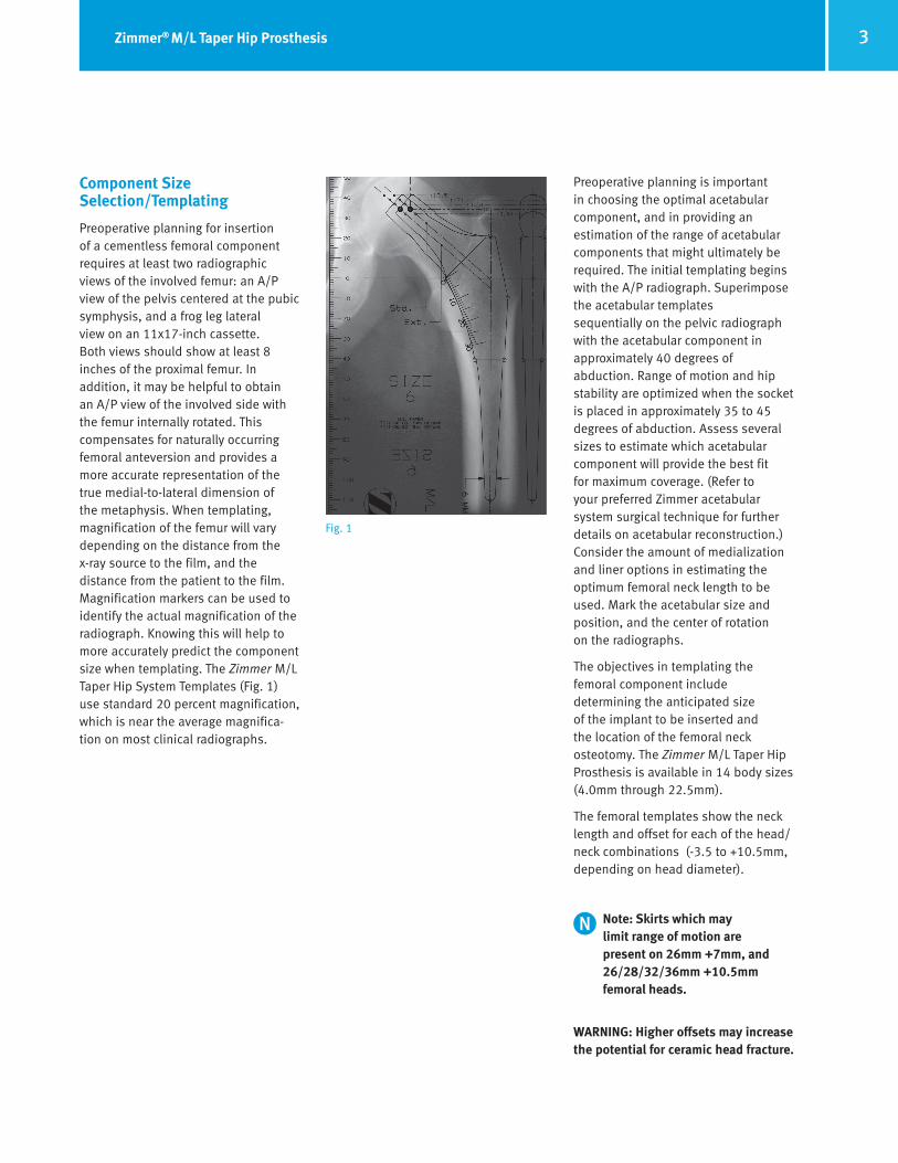
Preoperative planning for insertion of a cementless femoral component requires at least two radiographic views of the involved femur: an A/P view of the pelvis centered at the pubic symphysis, and a frog leg lateral view on an 11x17-inch cassette. Both views should show at least 8 inches of the proximal femur. In addition, it may be helpful to obtain an A/P view of the involved side with the femur internally rotated. This compensates for naturally occurring femoral anteversion and provides a more accurate representation of the true medial-to-lateral dimension of the metaphysis. When templating, magnification of the femur will vary depending on the distance from the x-ray source to the film, and the distance from the patient to the film. Magnification markers can be used to identify the actual magnification of the radiograph. Knowing this will help to more accurately predict the component size when templating. The Zimmer M/L Taper Hip System Templates (Fig. 1) use standard 20 percent magnification, which is near the average magnifica-tion on most clinical radiographs.
Preoperative planning is important in choosing the optimal acetabular component, and in providing an estimation of the range of acetabular components that might ultimately be required. The initial templating begins with the A/P radiograph. Superimpose the acetabular templates sequentially on the pelvic radiograph with the acetabular component in approximately 40 degrees of abduction. Range of motion and hip stability are optimized when the socket is placed in approximately 35 to 45 degrees of abduction. Assess several sizes to estimate which acetabular component will provide the best fit for maximum coverage. (Refer to your preferred Zimmer acetabular system surgical technique for further details on acetabular reconstruction.) Consider the amount of medialization and liner options in estimating the optimum femoral neck length to be used. Mark the acetabular size and position, and the center of rotation on the radiographs.
The objectives in templating the femoral component include determining the anticipated size of the implant to be inserted and the location of the femoral neck osteotomy. The Zimmer M/L Taper Hip Prosthesis is available in 14 body sizes (4.0mm through 22.5mm).
The femoral templates show the neck length and offset for each of the head/neck combinations (-3.5 to +10.5mm, depending on head diameter).
Note: Skirts which may limit range of motion are present on 26mm +7mm, and 26/28/32/36mm +10.5mm femoral heads.
WARNING: Higher offsets may increase the potential for ceramic head fracture.
Fig. 1

4 Zimmer® M/L Taper Hip Prosthesis
FA DRAFT August 11, 2014 11:44 AM
To estimate the femoral implant size, assess the body size on the A/P radiograph. Superimpose the template on the metaphysis and estimate the appropriate size of the femoral stem. The body of the femoral component should fit, or nearly fit, the medial- lateral dimensions of the medullary canal on the A/P x-ray film, and should not be superimposed onto cortical bone. It is not necessary for the stem to have cortical contact in the medul-lary canal.
After establishing the proper size of the femoral component, determine the height of its position in the proximal femur and the amount of offset needed to provide adequate abductor muscle tension. Generally, if the leg length and offset are to remain unchanged, the center of the head of the prosthesis should be at the same level as the center of the femoral head of the patient’s hip. This should also correspond to the center of rotation of the templated acetabulum. To lengthen the limb, raise the template proximally. To shorten the limb, shift the template distally. The extended offset option offers lateral translation of 5mm. This allows for an offset increase of 5mm without changing the vertical height or leg length. The femoral head neck length will also affect leg length and offset.
Once the height has been determined, note the distance in millimeters from the underside of the osteotomy line to the top of the lesser trochanter by using the millimeter scale on the template. For example, one might decide from the templating that a 52mm OD socket, with a size 15 prosthesis and a +3.5 x 28mm diameter femoral head, placed 15mm above the lesser trochanter, are the appropriate choices. Proximal/distal adjustments in prosthesis position can reduce the need for a femoral head with a skirt.
The Zimmer M/L Taper Hip System accommodates a variety of Zimmer head diameters with a 12/14 internal taper. The intermediate femoral heads allow the use of an acetabular compo-nent with an outside diameter small enough to seat completely in the bone while also allowing for a polyethylene liner of sufficient thickness. In special circumstances, such as the treatment of small patients and patients with congenital hip dysplasia and small acetabular volume, size 22mm heads are available.
5Zimmer® M/L Taper Hip Prosthesis
FA DRAFT August 11, 2014 11:44 AM
Surgical Technique
Exposure
In total hip arthroplasty, exposure can be achieved through a variety of methods based on the surgeon’s preference. The Zimmer M/L Taper Hip Prosthesis can be implanted using a variety of standard surgical approaches.
For more information regarding vari-ous surgical approaches, contact your Zimmer representative.
Determination of Leg Length
Establish landmarks and take measurements before dislocation of the hip so that after reconstruction, a comparison of leg length and femoral shaft offset can be obtained. From this comparison, adjustments can be made to achieve the goals established during preoperative planning. There are several methods to measure leg length. One method is to fix a leg length caliper to the wing of the ilium. Then, take baseline measurements to a cautery mark at the base of the greater trochanter while marking the position of the lower limb on the table.
Once neutral alignment has been determined, move the template proxi-mally or distally to the correct height as determined by preoperative planning. Then use electrocautery to inscribe a line across the femoral neck parallel to the base of the Osteotomy Guide.
Using the inscribed line as a guide, perform the osteotomy of the femoral neck. To prevent possible damage to the greater trochanter, stop the cut as the saw approaches the greater trochanter. Remove the saw and either bring it in from the superior portion of the femoral neck to complete the osteotomy cut, or use an osteotome to finish the cut.
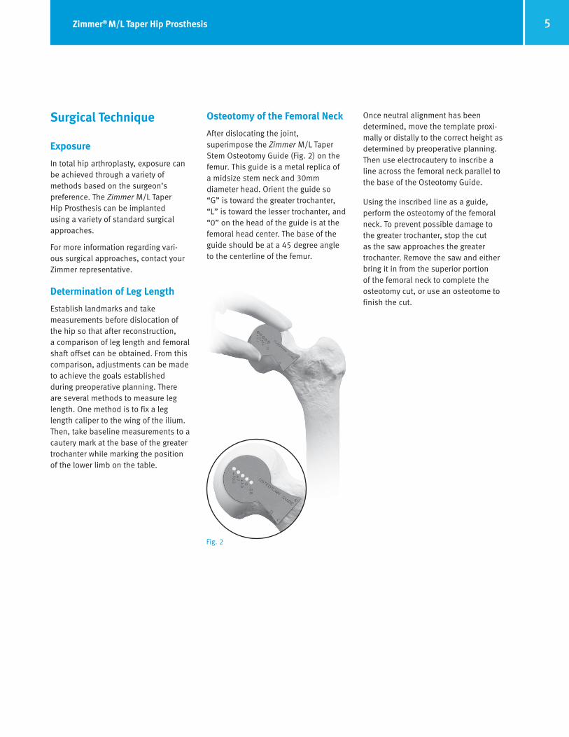
Osteotomy of the Femoral Neck
After dislocating the joint, superimpose the Zimmer M/L Taper Stem Osteotomy Guide (Fig. 2) on the femur. This guide is a metal replica of a midsize stem neck and 30mm diameter head. Orient the guide so “G” is toward the greater trochanter, “L” is toward the lesser trochanter, and “0” on the head of the guide is at the femoral head center. The base of the guide should be at a 45 degree angle to the centerline of the femur.
Fig. 2
6 Zimmer® M/L Taper Hip Prosthesis
FA DRAFT August 11, 2014 11:44 AM
Preparation of the Femur
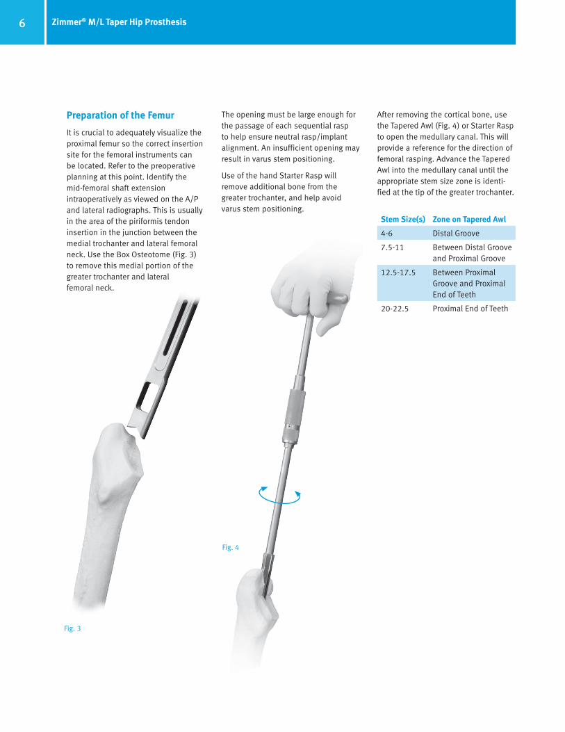
It is crucial to adequately visualize the proximal femur so the correct insertion site for the femoral instruments can be located. Refer to the preoperative planning at this point. Identify the mid-femoral shaft extension intraoperatively as viewed on the A/P and lateral radiographs. This is usually in the area of the piriformis tendon insertion in the junction between the medial trochanter and lateral femoral neck. Use the Box Osteotome (Fig. 3) to remove this medial portion of the greater trochanter and lateral femoral neck.
Fig. 4
Fig. 3
After removing the cortical bone, use the Tapered Awl (Fig. 4) or Starter Rasp to open the medullary canal. This will provide a reference for the direction of femoral rasping. Advance the Tapered Awl into the medullary canal until the appropriate stem size zone is identi-fied at the tip of the greater trochanter.
Stem Size(s) Zone on Tapered Awl
4-6 Distal Groove
7.5-11 Between Distal Groove and Proximal Groove
12.5-17.5 Between Proximal Groove and Proximal End of Teeth
20-22.5 Proximal End of Teeth
The opening must be large enough for the passage of each sequential rasp to help ensure neutral rasp/implant alignment. An insufficient opening may result in varus stem positioning.
Use of the hand Starter Rasp will remove additional bone from the greater trochanter, and help avoid varus stem positioning.
7Zimmer® M/L Taper Hip Prosthesis
FA DRAFT August 11, 2014 11:44 AM
Fig. 7
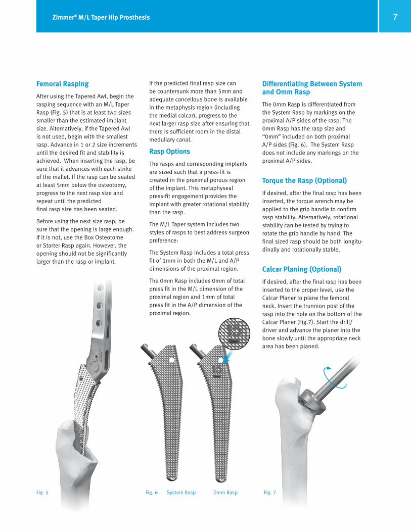
Femoral Rasping
After using the Tapered Awl, begin the rasping sequence with an M/L Taper Rasp (Fig. 5) that is at least two sizes smaller than the estimated implant size. Alternatively, if the Tapered Awl is not used, begin with the smallest rasp. Advance in 1 or 2 size increments until the desired fit and stability is achieved. When inserting the rasp, be sure that it advances with each strike of the mallet. If the rasp can be seated at least 5mm below the osteotomy, progress to the next rasp size and repeat until the predicted final rasp size has been seated.
Before using the next size rasp, be sure that the opening is large enough. If it is not, use the Box Osteotome or Starter Rasp again. However, the opening should not be significantly larger than the rasp or implant.
If the predicted final rasp size can be countersunk more than 5mm and adequate cancellous bone is available in the metaphysis region (including the medial calcar), progress to the next larger rasp size after ensuring that there is sufficient room in the distal medullary canal.
Rasp Options
The rasps and corresponding implants are sized such that a press-fit is created in the proximal porous region of the implant. This metaphyseal press-fit engagement provides the implant with greater rotational stability than the rasp.
The M/L Taper system includes two styles of rasps to best address surgeon preference:
The System Rasp includes a total press fit of 1mm in both the M/L and A/P dimensions of the proximal region.
The 0mm Rasp includes 0mm of total press fit in the M/L dimension of the proximal region and 1mm of total press fit in the A/P dimension of the proximal region.
Differentiating Between System and Omm Rasp
The 0mm Rasp is differentiated from the System Rasp by markings on the proximal A/P sides of the rasp. The 0mm Rasp has the rasp size and “0mm” included on both proximal A/P sides (Fig. 6). The System Rasp does not include any markings on the proximal A/P sides.
Torque the Rasp (Optional)
If desired, after the final rasp has been inserted, the torque wrench may be applied to the grip handle to confirm rasp stability. Alternatively, rotational stability can be tested by trying to rotate the grip handle by hand. The final sized rasp should be both longitu-dinally and rotationally stable.
Calcar Planing (Optional)
If desired, after the final rasp has been inserted to the proper level, use the Calcar Planer to plane the femoral neck. Insert the trunnion post of the rasp into the hole on the bottom of the Calcar Planer (Fig.7). Start the drill/driver and advance the planer into the bone slowly until the appropriate neck area has been planed.
Fig. 5 Fig. 6 System Rasp 0mm Rasp

8 Zimmer® M/L Taper Hip Prosthesis
FA DRAFT August 11, 2014 11:44 AM
Trial Reduction
Assemble the appropriately sized Neck Provisional and Femoral Head Provisional to the rasp (Fig. 8).
For the Standard or Extended Neck options, the size 4 neck provisional works with the size 4 rasp. The size 5-6 neck provisionals work with the size 5-6 rasps, and sizes 7.5-22.5 work with the remaining sizes.
For the Reduced Neck options, the size 4-9 neck provisionals work with the size 4-9 rasps. The size 10-12.5 neck provisionals work with the size 10-12.5 rasps, and sizes 13.5-22.5 work with the remaining sizes.
Visually verify that no gap is present between the neck provisional and the rasp area and the neck provisional and the femoral head provisional.
Refer to Zimmer VerSys® Trial Head Surgical Technique (97-8018-001-00) for proper femoral head provisional use.
Note: Verify etched size on rasp and provisionals before performing a trial reduction.
Fig. 9
Perform a trial reduction. Check the leg length and offset of the femur by referencing the lengths measured prior to dislocation of the hip. It is impor-tant at this stage to reposition the leg exactly where it was during the first measurement. Adjust the neck length by changing Femoral Head Provisionals to achieve the desired result. With the exception of 22mm heads, Femoral Head Provisionals are available with five neck lengths (-3.5mm to +10.5mm) which provide a total range of 14mm of neck length. When satisfactory leg length, offset, range of motion and sta-bility have been achieved, dislocate the hip. Remove the rasp and provisionals, use the provisional size markings to confirm desired implant size(s).
Insertion of the Femoral Component
Insert the implant into the canal until it will no longer advance with hand pressure, which is approximately 1 to 2 cm above the final seated position. (Fig. 9). The Standard Stem Driver has a tear-drop-shaped tip to allow the surgeon to control intitial rotation during insertion. An optional Round Tip Stem Driver is also available to allow rotational freedom during insertion.
Allow the stem to follow the prepared envelope, to better avoid any potential for fracture. The insertion hole on the implant will accept either tip.
Apply the Stem Driver to the implant and begin to tap the handle with a mallet until the implant will no longer advance (Fig. 10).
Note: Do not continue to try to advance the prosthesis once it has made contact with the cortical bone in the medial calcar.
The prosthesis should be seated when the most proximal part of the porous surface is level with the osteotomy line. If the implant does not advance with each strike of the mallet, stop insertion and remove the component. Then, rasp or ream additional bone from the areas that are preventing the insertion and insert the component again.
Note: If using both the System Rasps and the 0mm Rasps, and specifically if switching from the System Rasps to the 0mm Rasps, begin the rasping sequence with a 0mm Rasp that is at least one size smaller than the last System Rasp size used.
Fig. 8 Fig. 10

9Zimmer® M/L Taper Hip Prosthesis
FA DRAFT August 11, 2014 11:44 AM
Optional Insertion Technique
If preferred, a Stem Inserter can be used to impact the implant (Fig. 11).
Attach the Stem Inserter to the selected femoral implant. To facilitate alignment, the Stem Inserter has three holes that will accept 1/8” diameter Steinmann pins. The holes are marked for 0, 7.5, and 15 degrees of anteversion.
Note: When disengaging the Stem Inserter, listen for an audible click to confirm that the instrument is completely released from the stem.
Fig. 11
Femoral Component Extraction
An Extraction Hook to remove the femoral component is included in the instrument set (Fig. 12). If the femoral component is removed, do not re-insert it. Implant a new femoral component.
Attachment of the Femoral Head
Once the implant is fully seated in the femoral canal, place the selected Femoral Head Provisional onto the taper of the implant. Perform a trial reduction to assess joint stability, range of motion, and restoration of leg length and offset. When the appropriate femoral head implant is confirmed, remove the Femoral Head Provisional and check to ensure that the 12/14 taper is clean and dry.
Fig. 12
Then place the selected femoral head on the taper and secure it firmly by twisting it and striking it once with the Head Impactor (Fig. 13). Test the security of the head fixation by trying to remove it by hand.
Note: Do not impact the femoral head onto the taper before driving in the prosthesis as the femoral head may loosen during impaction.
Reduce the hip and assess leg length, range of motion, stability, and abductor tension for the final time.
Wound Closure
After obtaining hemostasis, insert a Hemovac® Wound Drainage Device and close the wound in layers.
Postoperative ManagementThe postoperative management of patients with a Zimmer M/L Taper Hip Prosthesis is determined by the surgical technique, patient’s bone quality, fit of the implant, and the surgeon’s judgment.
Fig. 13
10 Zimmer® M/L Taper Hip Prosthesis
FA DRAFT August 11, 2014 11:44 AM
A
B
EC
DF
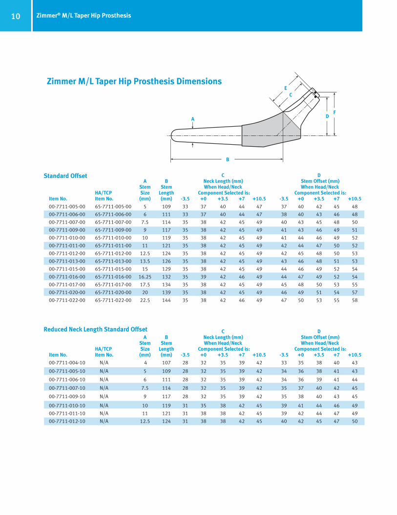
Zimmer M/L Taper Hip Prosthesis Dimensions
Standard Offset C D A B Neck Length (mm) Stem Offset (mm) Stem Stem When Head/Neck When Head/Neck HA/TCP Size Length Component Selected is: Component Selected is:Item No. Item No. (mm) (mm) -3.5 +0 +3.5 +7 +10.5 -3.5 +0 +3.5 +7 +10.5
00-7711-005-00 65-7711-005-00 5 109 33 37 40 44 47 37 40 42 45 48
00-7711-006-00 65-7711-006-00 6 111 33 37 40 44 47 38 40 43 46 48
00-7711-007-00 65-7711-007-00 7.5 114 35 38 42 45 49 40 43 45 48 50
00-7711-009-00 65-7711-009-00 9 117 35 38 42 45 49 41 43 46 49 51
00-7711-010-00 65-7711-010-00 10 119 35 38 42 45 49 41 44 46 49 52
00-7711-011-00 65-7711-011-00 11 121 35 38 42 45 49 42 44 47 50 52
00-7711-012-00 65-7711-012-00 12.5 124 35 38 42 45 49 42 45 48 50 53
00-7711-013-00 65-7711-013-00 13.5 126 35 38 42 45 49 43 46 48 51 53
00-7711-015-00 65-7711-015-00 15 129 35 38 42 45 49 44 46 49 52 54
00-7711-016-00 65-7711-016-00 16.25 132 35 39 42 46 49 44 47 49 52 54
00-7711-017-00 65-7711-017-00 17.5 134 35 38 42 45 49 45 48 50 53 55
00-7711-020-00 65-7711-020-00 20 139 35 38 42 45 49 46 49 51 54 57
00-7711-022-00 65-7711-022-00 22.5 144 35 38 42 46 49 47 50 53 55 58
C D A B Neck Length (mm) Stem Offset (mm) Stem Stem When Head/Neck When Head/Neck HA/TCP Size Length Component Selected is: Component Selected is:Item No. Item No. (mm) (mm) -3.5 +0 +3.5 +7 +10.5 -3.5 +0 +3.5 +7 +10.5
00-7711-004-10 N/A 4 107 28 32 35 39 42 33 35 38 40 43 00-7711-005-10 N/A 5 109 28 32 35 39 42 34 36 38 41 43
00-7711-006-10 N/A 6 111 28 32 35 39 42 34 36 39 41 44
00-7711-007-10 N/A 7.5 114 28 32 35 39 42 35 37 40 42 45
00-7711-009-10 N/A 9 117 28 32 35 39 42 35 38 40 43 45
00-7711-010-10 N/A 10 119 31 35 38 42 45 39 41 44 46 49
00-7711-011-10 N/A 11 121 31 38 38 42 45 39 42 44 47 49
00-7711-012-10 N/A 12.5 124 31 38 38 42 45 40 42 45 47 50
Reduced Neck Length Standard Offset
11Zimmer® M/L Taper Hip Prosthesis
FA DRAFT August 11, 2014 11:44 AM
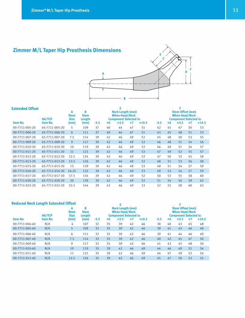
E F A B Neck Length (mm) Stem Offset (mm) Stem Stem When Head/Neck When Head/Neck HA/TCP Size Length Component Selected is: Component Selected is:Item No. Item No. (mm) (mm) -3.5 +0 +3.5 +7 +10.5 -3.5 +0 +3.5 +7 +10.5
00-7711-005-20 65-7711-005-20 5 109 37 40 44 47 51 42 45 47 50 53
00-7711-006-20 65-7711-006-20 6 111 37 40 44 47 51 43 45 48 51 53
00-7711-007-20 65-7711-007-20 7.5 114 39 42 46 49 52 45 48 50 53 55
00-7711-009-20 65-7711-009-20 9 117 39 42 46 49 52 46 48 51 54 56
00-7711-010-20 65-7711-010-20 10 119 39 42 46 49 52 46 49 51 54 57
00-7711-011-20 65-7711-011-20 11 121 39 42 46 49 53 47 49 52 55 57
00-7711-012-20 65-7711-012-20 12.5 124 39 42 46 49 52 47 50 53 55 58
00-7711-013-20 65-7711-013-20 13.5 126 39 42 46 49 52 48 51 53 56 58
00-7711-015-20 65-7711-015-20 15 129 39 42 46 49 53 49 51 54 57 59
00-7711-016-20 65-7711-016-20 16.25 132 39 42 46 49 53 49 52 54 57 59
00-7711-017-20 65-7711-017-20 17.5 134 39 42 46 49 52 50 53 55 58 60
00-7711-020-20 65-7711-020-20 20 139 39 42 46 49 52 51 54 56 59 62
00-7711-022-20 65-7711-022-20 22.5 144 39 42 46 49 53 52 55 58 60 63
E F A B Neck Length (mm) Stem Offset (mm) Stem Stem When Head/Neck When Head/Neck HA/TCP Size Length Component Selected is: Component Selected is:Item No. Item No. (mm) (mm) -3.5 +0 +3.5 +7 +10.5 -3.5 +0 +3.5 +7 +10.5
00-7711-004-40 N/A 4 107 32 35 39 42 46 38 40 43 45 4800-7711-005-40 N/A 5 109 32 35 39 42 46 39 41 43 46 48
00-7711-006-40 N/A 6 111 32 35 39 42 46 39 41 44 46 49
00-7711-007-40 N/A 7.5 114 32 35 39 42 46 40 42 45 47 50
00-7711-009-40 N/A 9 117 32 35 39 42 46 41 43 45 48 50
00-7711-010-40 N/A 10 119 35 39 42 46 49 44 46 49 51 54
00-7711-011-40 N/A 11 121 35 39 42 46 49 44 47 49 52 54
00-7711-012-40 N/A 12.5 124 35 39 42 46 49 45 47 50 52 55
Extended Offset
A
B
EC
DF
Zimmer M/L Taper Hip Prosthesis Dimensions
Reduced Neck Length Extended Offset
A12 Zimmer® M/L Taper Hip Prosthesis
FA DRAFT August 11, 2014 11:44 AM
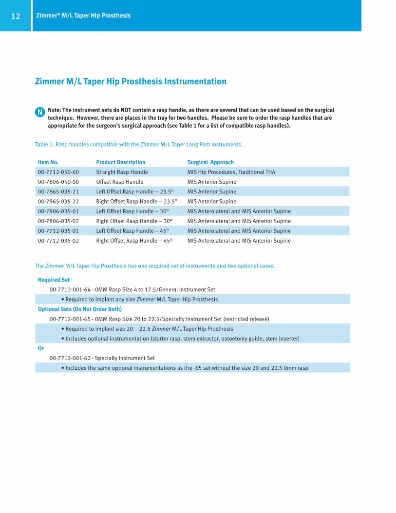
Zimmer M/L Taper Hip Prosthesis Instrumentation
Note: The instrument sets do NOT contain a rasp handle, as there are several that can be used based on the surgical technique. However, there are places in the tray for two handles. Please be sure to order the rasp handles that are appropriate for the surgeon’s surgical approach (see Table 1 for a list of compatible rasp handles).
Table 1. Rasp handles compatible with the Zimmer M/L Taper Long Post Instruments.
Item No. Product Description Surgical Approach
00-7712-050-60 Straight Rasp Handle MIS Hip Procedures, Traditional THA
00-7806-050-00 Offset Rasp Handle MIS Anterior Supine
00-7865-035-21 Left Offset Rasp Handle – 23.5° MIS Anterior Supine
00-7865-035-22 Right Offset Rasp Handle – 23.5° MIS Anterior Supine
00-7806-035-01 Left Offset Rasp Handle – 30° MIS Anterolateral and MIS Anterior Supine
00-7806-035-02 Right Offset Rasp Handle – 30° MIS Anterolateral and MIS Anterior Supine
00-7712-035-01 Left Offset Rasp Handle – 45° MIS Anterolateral and MIS Anterior Supine
00-7712-035-02 Right Offset Rasp Handle – 45° MIS Anterolateral and MIS Anterior Supine
The Zimmer M/L Taper Hip Prosthesis has one required set of instruments and two optional cases.
Required Set
00-7712-001-64 - 0MM Rasp Size 4 to 17.5/General Instrument Set
• Required to implant any size Zimmer M/L Taper Hip Prosthesis
Optional Sets (Do Not Order Both)
00-7712-001-65 - 0MM Rasp Size 20 to 22.5/Specialty Instrument Set (restricted release)
• Required to implant size 20 – 22.5 Zimmer M/L Taper Hip Prosthesis
• Includes optional instrumentation (starter rasp, stem extractor, ostoetomy guide, stem inserter)
Or
00-7712-001-62 - Specialty Instrument Set
• Includes the same optional instrumentations as the -65 set without the size 20 and 22.5 0mm rasp
13Zimmer® M/L Taper Hip Prosthesis
FA DRAFT August 11, 2014 11:44 AM
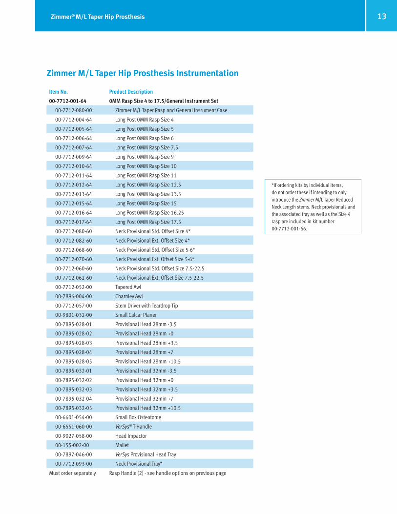
Item No. Product Description
00-7712-001-64 0MM Rasp Size 4 to 17.5/General Instrument Set
00-7712-080-00 Zimmer M/L Taper Rasp and General Insrument Case
00-7712-004-64 Long Post 0MM Rasp Size 4
00-7712-005-64 Long Post 0MM Rasp Size 5
00-7712-006-64 Long Post 0MM Rasp Size 6
00-7712-007-64 Long Post 0MM Rasp Size 7.5
00-7712-009-64 Long Post 0MM Rasp Size 9
00-7712-010-64 Long Post 0MM Rasp Size 10
00-7712-011-64 Long Post 0MM Rasp Size 11
00-7712-012-64 Long Post 0MM Rasp Size 12.5
00-7712-013-64 Long Post 0MM Rasp Size 13.5
00-7712-015-64 Long Post 0MM Rasp Size 15
00-7712-016-64 Long Post 0MM Rasp Size 16.25
00-7712-017-64 Long Post 0MM Rasp Size 17.5
00-7712-080-60 Neck Provisional Std. Offset Size 4*
00-7712-082-60 Neck Provisional Ext. Offset Size 4*
00-7712-068-60 Neck Provisional Std. Offset Size 5-6*
00-7712-070-60 Neck Provisional Ext. Offset Size 5-6*
00-7712-060-60 Neck Provisional Std. Offset Size 7.5-22.5
00-7712-062-60 Neck Provisional Ext. Offset Size 7.5-22.5
00-7712-052-00 Tapered Awl
00-7896-004-00 Charnley Awl
00-7712-057-00 Stem Driver with Teardrop Tip
00-9801-032-00 Small Calcar Planer
00-7895-028-01 Provisional Head 28mm -3.5
00-7895-028-02 Provisional Head 28mm +0
00-7895-028-03 Provisional Head 28mm +3.5
00-7895-028-04 Provisional Head 28mm +7
00-7895-028-05 Provisional Head 28mm +10.5
00-7895-032-01 Provisional Head 32mm -3.5
00-7895-032-02 Provisional Head 32mm +0
00-7895-032-03 Provisional Head 32mm +3.5
00-7895-032-04 Provisional Head 32mm +7
00-7895-032-05 Provisional Head 32mm +10.5
00-6601-054-00 Small Box Osteotome
00-6551-060-00 VerSys® T-Handle
00-9027-058-00 Head Impactor
00-155-002-00 Mallet
00-7897-046-00 VerSys Provisional Head Tray
00-7712-093-00 Neck Provisional Tray*
Must order separately Rasp Handle (2) - see handle options on previous page
Zimmer M/L Taper Hip Prosthesis Instrumentation
*If ordering kits by individual items,do not order these if intending to onlyintroduce the Zimmer M/L Taper ReducedNeck Length stems. Neck provisionals andthe associated tray as well as the Size 4rasp are included in kit number00-7712-001-66.

A14 Zimmer® M/L Taper Hip Prosthesis
FA DRAFT August 11, 2014 11:44 AM
Item No. Product Description
00-7712-001-66 M/L Taper Reduced Neck 4 – 12.5 Cone Provisional Upgrade Kit
00-7712-072-60 Neck Provisional Size 4 – 9 Std. Offset
00-7712-074-60 Neck Provisional Size 4 – 9 Ext. Offset
00-7712-076-60 Neck Provisional Size 10 – 12.5 Std. Offset
00-7712-078-60 Neck Provisional Size 10 – 12.5 Ext. Offset
00-7712-094-00 Neck Provisional Tray Size 4 – 12.5
00-7712-004-64 M/L Taper Size 4 Long Post 0MM Rasp
Item No. Product Description
00-7712-001-65 0MM Rasp Size 20 to 22.5/Specialty Instrument Set
00-7712-085-00 Zimmer M/L Taper Rasp and Specialty Instrument Case
00-7803-065-00 Hand Starter Rasp
00-7712-020-64 Long Post 0MM Rasp Size 20
00-7712-022-64 Long Post 0MM Rasp Size 22.5
00-7712-063-00 Extractor Hook
00-7712-056-00 Stem Inserter
00-7712-054-00 Osteotomy Guide

15Zimmer® M/L Taper Hip Prosthesis
FA DRAFT August 11, 2014 11:44 AM
Zimmer M/L Taper Hip Prosthesis Instrumentation
Item No. Product Description
00-7712-001-62 Specialty Instrument Set (same as -65, but less rasps)
00-7712-085-00 Zimmer M/L Taper Rasp and Specialty Instrument Case
00-7803-065-00 Hand Starter Rasp
00-7712-063-00 Extractor Hook
00-7712-056-00 Stem Inserter
00-7712-054-00 Osteotomy Guide
Item No. Product Description
Miscellaneous Instruments Order Separately
00-7712-085-00 Zimmer M/L Taper Rasp and Specialty Instrument Case
00-6601-030-00 Anatomic Hip Square Drive Torque Wrench 3/8 inch
00-7712-004-60 Long Post Rasp Size 4
00-7712-005-60 Long Post Rasp Size 5
00-7712-006-60 Long Post Rasp Size 6
00-7712-007-60 Long Post Rasp Size 7.5
00-7712-009-60 Long Post Rasp Size 9
00-7712-010-60 Long Post Rasp Size 10
00-7712-011-60 Long Post Rasp Size 11
00-7712-012-60 Long Post Rasp Size 12.5
00-7712-013-60 Long Post Rasp Size 13.5
00-7712-015-60 Long Post Rasp Size 15
00-7712-016-60 Long Post Rasp Size 16.25
00-7712-017-60 Long Post Rasp Size 17.5
00-7712-020-60 Long Post Rasp Size 20
00-7712-022-60 Long Post Rasp Size 22.5
00-7712-055-00 Zimmer M/L Taper Torque Wrench Adapter 3/8 inch
00-7803-057-00 MIS Provisional Head Inserter
00-7712-064-00 Stem Driver with Round Tip

Contact your Zimmer Representative or visit us at www.zimmer.com
97-7711-202-00 Rev. 1 MC0000119778 7/17/14 Printed in USA ©2014 Zimmer Inc.
The CE mark is valid only if it is also printed on the product label.
This documentation is intended exclusively for physicians and is not intended for laypersons.Information on the products and procedures contained in this document is of a general natureand does not represent and does not constitute medical advice or recommendations. Becausethis information does not purport to constitute any diagnostic or therapeutic statement withregard to any individual medical case, each patient must be examined and advised individually,and this document does not replace the need for such examination and/or advice in whole orin part. Please refer to the package inserts for important product information, including, but notlimited to, contraindications, warnings, precautions, and adverse effects.


![in.chineseembassy.orgin.chineseembassy.org/chn/lsfw/P020180927692869987159.pdf · 48mm*33mm, 15mm-22mm, 28mm-33mm, —Z 5k, C] ákJ . ± 48mm*33mm, 15mm-22mm, 28mm-33mm, , El-J ,](https://static.fdocuments.net/doc/165x107/5f0d73a67e708231d43a6c7d/in-48mm33mm-15mm-22mm-28mm-33mm-az-5k-c-kj-48mm33mm-15mm-22mm.jpg)


