Zimmer Continuum Acetabular System - zgreatlakes.comzgreatlakes.com/Literature/Hips/97-7255-078-00...
24
Zimmer ® Continuum ™ Acetabular System Surgical Technique Bringing together proven technologies.
Transcript of Zimmer Continuum Acetabular System - zgreatlakes.comzgreatlakes.com/Literature/Hips/97-7255-078-00...

1
Zimmer® Continuum™ Acetabular
System
Surgical Technique
Bringing together proven technologies.

2 Surgical Technique
Device Description• The Continuum Shell is hemispherical in shape with an exterior
of Trabecular Metal™ Material that is bonded to a Tivanium® alloy substrate. The shell has a snap fit locking groove for acceptance of the Longevity® Highly Crosslinked Polyethylene Neutral. Twelve scallops, equally spaced in 30° increments, included on the shell face mate with twelve anti-rotation tabs on the Longevity Liners. The shell also has an integrated locking taper mechanism deigned to accept Metasul® Hard Bearing Liners.
Indications/Intended UseLongevity Polyethylene Liners• The system is indicated for primary or revision surgery in
skeletally mature individuals for rehabilitating hips damaged as a result of noninflammatory degenerative joint disease (NIDJD) or its composite diagnoses of osteoarthritis, avascular necrosis, protrusio acetabuli, traumatic arthritis, slipped capital epiphysis, fused hip, fracture of the pelvis, and diastrophic variant.
• The system is intended for use either with or without bone cement in total hip arthroplasty.
Metasul Metal-on-Metal Technology• Noninflammatory degenerative joint disease (NIDJD) including
avascular necrosis, osteoarthritis, post-traumatic arthritis and congenital hip dysplasia and inflammatory joint disease (IJD), e.g. rheumatoid arthritis if bone quality is adequate.
• Failed previous surgery where pain, deformity, or dysfunction persists.
• Revision of previously failed hip arthroplasty.
• Total hip replacements may be considered for younger patients if any unequivocal indication outweighs the risks associated with the age of the patient and modified demands regard-ing activity and hip joint loading are assured. This includes severely handicapped patients with multiple joint involvement, for whom an immediate need of hip mobility leads to an expec-tation of significant improvement in the quality of their lives.
• The system is intended for use either with or without bone
cement in total hip arthroplasty.
3Surgical Technique
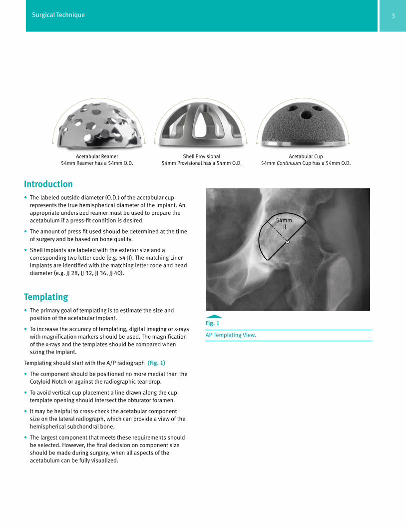
Shell Provisional 54mm Provisional has a 54mm O.D.
Acetabular Reamer 54mm Reamer has a 54mm O.D.
Acetabular Cup 54mm Continuum Cup has a 54mm O.D.
Introduction • The labeled outside diameter (O.D.) of the acetabular cup
represents the true hemispherical diameter of the Implant. An appropriate undersized reamer must be used to prepare the acetabulum if a press-fit condition is desired.
• The amount of press fit used should be determined at the time of surgery and be based on bone quality.
• Shell Implants are labeled with the exterior size and a corresponding two letter code (e.g. 54 JJ). The matching Liner Implants are identified with the matching letter code and head diameter (e.g. JJ 28, JJ 32, JJ 36, JJ 40).
Templating• The primary goal of templating is to estimate the size and
position of the acetabular Implant.
• To increase the accuracy of templating, digital imaging or x-rays with magnification markers should be used. The magnification of the x-rays and the templates should be compared when sizing the Implant.
Templating should start with the A/P radiograph (Fig. 1)
• The component should be positioned no more medial than the Cotyloid Notch or against the radiographic tear drop.
• To avoid vertical cup placement a line drawn along the cup template opening should intersect the obturator foramen.
• It may be helpful to cross-check the acetabular component size on the lateral radiograph, which can provide a view of the hemispherical subchondral bone.
• The largest component that meets these requirements should be selected. However, the final decision on component size should be made during surgery, when all aspects of the acetabulum can be fully visualized.
Fig. 1 AP Templating View.
54mm JJ

4 Surgical Technique
Acetabular Reaming • From templating and preoperative planning, determine the
desired head position.
• Start with a smaller reamer, then progress to the next largest size until exposing bleeding cancellous bone.
Note: Take extra care to avoid eccentric reaming by holding the reamer steady. Apply constant pressure in the recommended final Implant orientation of 45 degrees of abduction and 20 degrees of forward flexion.
Shell Provisional Insertion and Alignment• Proper care must be taken to assess bone quality and to
determine the appropriate Implant size and type.
• Place the Shell Inserter Adaptor, with or without Rotational Control, onto the tip of either the Straight or Offset Hybrid Shell Inserter.
• Insert a Ball Head Hex Driver through the window and into the Locking Screw at the tip of the Inserter. (Fig. 2)
• Place the selected size Shell Provisional over the tip of the Adaptor so the square tip of the Adaptor mates with the square recess at the pole of the Provisional. (Fig. 3)
• While holding the Shell Provisional in place, securely thread the Locking Screw into the Polar Hole of the Shell Provisional.
• Attach the Alignment Frame to the Inserter and tighten the Thumb Screw.
See the following diagrams for use instructions on the lateral and supine approaches (Pages 14, 15, 16, 17).
Fig. 3 The Shell Inserter with Adaptor mating with the Provisional Shell.
Fig. 2
Attaching the Shell Provisional to the Inserter Handle using the Hex-Head Driver.

5Surgical Technique
Note: The Alignment Support Frame on the Shell Inserter will not be vertical to the floor and should not be used as a positioning guide. (Fig. 4) The arms on the Guide are used to correctly position the Provisional Shell and/or Implant (Pages 14, 15, 16, 17).
• With the Shell Provisional in the appropriate alignment, use a mallet to impact the handle of the Inserter.
• When the Shell Provisional is fully seated, turn the Driver counterclockwise to loosen the Attachment Screw on the Inserter.
• Remove the Inserter.
The Shell Provisional has fenestrations to assess proper cup seating inside the acetabulum.
Provisional Liner Insertion Inserting the Provisional Liner
• Select the Provisional Liner size that matches the selected Provisional Shell.
• The selected Shell Provisional will be identified through a size and a two letter code (e.g. 50 HH). There are different inner diameter Implant sizes available for each Shell size. The Provisional Liner will be identified by letter code matching the Shell diameter and desired inner diameter (e.g. 32 HH).
• Use a Hex-head Driver to insert the Provisional Locking Screw through the Polar Hole of the Provisional Liner. The Provisional Locking Screw will have a silver ring. The smallest Liners in head sizes 36 and 40 (HH 36 and JJ 40) do not have a Locking Screw and seat with a peg feature.
• Insert the Provisional Liner by hand into the Shell Provisional.
Note: Do not impact the Provisional Liner as damage may occur.
• Thread the Locking Screw into the Polar Hole of the Shell Provisional.
Trial Range of Motion• Insert a head/neck Provisional onto the Implanted Stem or Rasp
Cone Provisional and perform a trial reduction.
• Check for stability and range of motion.
• Remove the Provisional components.
Note: Refer to Zimmer’s product compatibility website, www.productcompatibility.zimmer.com, to determine compatibility among all selected components.
Fig. 4 Do not use the support frame to align the Provisional Shell or Shell Implant.

6 Surgical Technique
* Wasielewski RC, Cooperstein LA, Kruger MP, Rubash HE. Acetabular anatomy and
the transacetabular fixation of screws in total hip arthroplasty. J Bone Joint Surg.
1990:72-A(4);501-508.
PosteriorSuperior
AnteriorInferior
PosteriorInferiorAnterior
Superior
Implant Insertion• As previously mentioned, there are two Adaptors for the Inserter
Handles. The Adaptor with Rotational Control Locks to prevent the Implant from rotating freely on the Inserter handle. If this Adaptor is used with a Cluster Hole Shell, the dark etch on the Adaptor should be in line with the alignment frame on the Inserter to allow for Cluster Hole placement in the posterior superior and posterior inferior quadrants.
Note: The Shell Inserter Adaptor without Rotational Control will allow the Implant to rotate freely on the Inserter. Use this Adaptor when it is necessary to position the Screw Holes in a specific location within the acetabulum.
• The Shell Inserter Adaptor with Rotational control has two pins that will fit into slots at the tip of the Inserter. These pins are not found on the Shell Inserter Adaptor without Rotational Control.
• Insert a Ball Hex Head Driver through the opening and into the Locking Screw at the tip of the Inserter.
• Place the Implant over the tip of the Adaptor so the square tip of the Adaptor mates with the square recess at the pole of the Implant.
• While holding the Implant in place, securely thread the locking Screw into the Polar Hole of the Implant. Excessive torque forces may cause damage to the thread of the Polar Hole.
• Ensure that the patient is in the correct position for the selected surgical approach.
• Attach the Alignment Frame to the Inserter and tighten the Thumb Screw.
• With the final prosthesis connected to the Shell Inserter, insert the Implant into the prepared acetabulum.
• To achieve 45 degrees of abduction and 20 degrees of forward flexion:
· When using the Lateral Alignment Guide, ensure that the Lateral Frame is parallel to the floor, and that the anterior rod of the Alignment Frame is in line with the patient’s torso. (Page 14, Fig. 20)
· When using the Supine Alignment Guide, align the Lateral Arm of the guide with the long axis of the body. (Page 16, Fig. 22)
Fig. 5 Correct location for Screw placement in shaded regions.
Note: The potential for neurologic and vascular injury can be minimized if the posterior quadrants are used for transacetabular screw placement.* The Shell should be positioned to allowscrew placement in the posterior superior and/or posterior inferior quadrants of the acetabulum. (Fig. 5) The Continuum Screw Holes are located closer to the Polar region as compared to the Trabecular Metal™ Shell.
• With the Implant in the appropriate position and alignment, use a mallet to impact the handle of the Inserter.
• When the Implant is fully seated, turn the Driver counterclockwise to loosen the Attachment Screw on the Inserter.
• Remove the Inserter.
Note: The impact required to seat the Implant is dictated by the bone quality.
Note: Do not lever on the Shell or the cup Inserter to reposition the Implant, as damage may occur to the threads or inner diameter of the Shell.

7Surgical Technique
Screw InsertionIf Screw placement is desired:
• Carefully following these steps for Screw insertion can help to minimize Screw push through or torque out after initial Implantation.
• Drill a pilot hole, using either a Modular or One-Piece Flex Drill.
• If using th Modular Flex Drill attach the selected bit using the Hex Wrench. (Fig. 6) Check the bit to ensure that it is not dull.
• Position the Adjustable Drill Guide and Flex Drill into the selected Screw Hole. (Fig. 7)
• For sclerotic bone, an option may be to tap the Screw hole.
· Attach the Modular Tap Shaft into the Modular Handle by pulling back on the snap-lock collet and aligning the hole in the shaft with the etched line on the collet.
· Attach the appropriate Tap to the Modular Tap Shaft.
· Bicortical tapping the entire depth should be done with care by turning the Tap Handle clockwise.
Fig. 6 Attaching the bit to the Flex Drill with the Hex Wrench.
Fig. 7
Inserting the Adjustable Drill Guide and Modular Flex Shaft into the Shell.

8 Surgical Technique
After drilling the pilot or tapping the Screw hole:
• Use the Depth Gauge to measure the depth of the Screw hole. (Fig. 8)
• Select the appropriate length Trilogy® Screw.
• Use a Screwdriver to insert it into the selected Screw hole. Screws cannot be inserted into the Polar Hole at the dome of the Shell. (Fig. 9)
• Check to ensure that the heads of inserted Screws are below the inner diameter of the cup. Screw heads that protrude into the inner Shell can prevent adequate seating of the Insert. (Fig. 10)
• Place additional Screws as necessary.
• Carefully evaluate the bone quality, and avoid over tightening the Screws.
• To remove a Screw, engage the Screw with a Hex-head Driver and turn it counter clock wise.
Warning: Avoid Screw placement through the Shell into the anterior inferior and anterior superior quadrants of the acetabulum to prevent injury to the neurovascular structures.
Fig. 8 Using the Depth Gauge to measure the screw hole depth.
Fig. 9 Using a scewdriver to insert the screws.
Fig. 10 Checking to ensure that the screws are properly seated.
9Surgical Technique
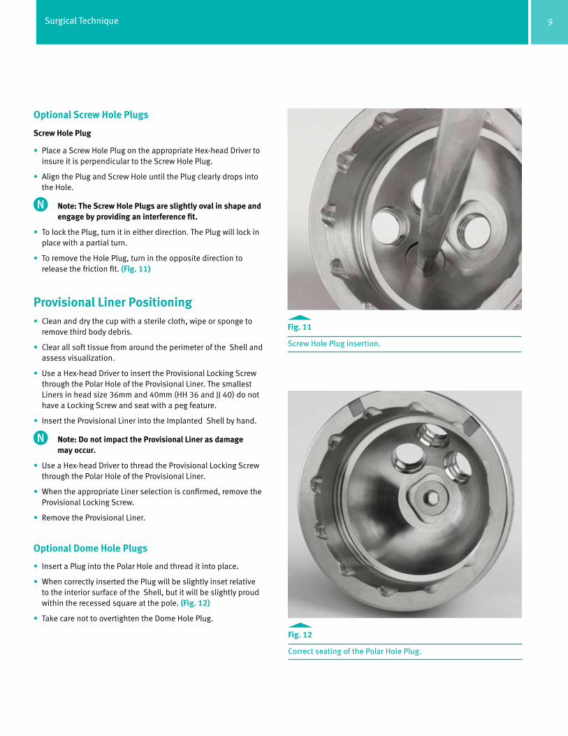
Optional Screw Hole Plugs
Screw Hole Plug
• Place a Screw Hole Plug on the appropriate Hex-head Driver to insure it is perpendicular to the Screw Hole Plug.
• Align the Plug and Screw Hole until the Plug clearly drops into the Hole.
Note: The Screw Hole Plugs are slightly oval in shape and engage by providing an interference fit.
• To lock the Plug, turn it in either direction. The Plug will lock in place with a partial turn.
• To remove the Hole Plug, turn in the opposite direction to release the friction fit. (Fig. 11)
Provisional Liner Positioning• Clean and dry the cup with a sterile cloth, wipe or sponge to
remove third body debris.
• Clear all soft tissue from around the perimeter of the Shell and assess visualization.
• Use a Hex-head Driver to insert the Provisional Locking Screw through the Polar Hole of the Provisional Liner. The smallest Liners in head size 36mm and 40mm (HH 36 and JJ 40) do not have a Locking Screw and seat with a peg feature.
• Insert the Provisional Liner into the Implanted Shell by hand.
Note: Do not impact the Provisional Liner as damage may occur.
• Use a Hex-head Driver to thread the Provisional Locking Screw through the Polar Hole of the Provisional Liner.
• When the appropriate Liner selection is confirmed, remove the Provisional Locking Screw.
• Remove the Provisional Liner.
Optional Dome Hole Plugs
• Insert a Plug into the Polar Hole and thread it into place.
• When correctly inserted the Plug will be slightly inset relative to the interior surface of the Shell, but it will be slightly proud within the recessed square at the pole. (Fig. 12)
• Take care not to overtighten the Dome Hole Plug.
Fig. 11 Screw Hole Plug insertion.
Fig. 12 Correct seating of the Polar Hole Plug.

10 Surgical Technique
Liner Insertion Instrument Metasul® Liners
• Prior to inserting the Metasul Liner, ensure the interior of the Shell and the Liner and Liner Insertion Tool are clean and dry. Also inspect the Shell to ensure that no damage occurred to the taper, Dome hole Plugs or Screw hole Plugs.
• Metasul Liners can be inserted by hand or using the Liner Insertion Tool.
• If using the Liner Insertion Tool, follow these Assembly Instructions:
· Insert the suction tip onto the shaft of the Instrument up to the etch line. Ensure that the shaft is bottomed out in the suction tip. · Saline or water can be used to lubricate the suction cup for easier assembly.
· Engage Liner and Liner Insertion Tool by depressing the suction cup in the liner.
· Insert the liner into the Shell.
· Remove the liner inserter tool by lifting up on the interior rod to release the vacuum. (Fig. 13)
Note: Do not impact the Liner Insertion Instrument. This is indicated on the Instrument using the following symbol.
• Select the correct size Hard Bearing Rim Impactor which will match the implant head size (32mm, 36mm or 40mm).
• Attach the Hard Bering Rim Impactor to either the straight or curved Universal Handle by aligning the pins on the Universal Handle with the keyhole slot on the underside of the Impactor. (Fig. 14)
• Push the Impactor onto the handle and twist it in either direction to lock it in place.
Fig. 14 Hard Bearing Rim Impactor.
Fig. 13 Disengaging the Liner Insertion Instrument.

11Surgical Technique
• Center the Metasul Liner by rocking the Universal Handle with the attached Hard Bearing Rim Impactor prior to impaction. (Fig. 15) This will decrease the likelihood of incorrect liner seating.
• Palpate the liner to ensure it is uniformly seated prior to Impaction.
• Place the Hard Bearing Rim Impactor or Dome Impactor on the liner.
• Firmly strike the Universal Handle once with a mallet to fully seat the liner.
• Verify that the liner is properly inserted. When fully inserted, it should be flush and level to the face of the Shell. (Fig. 16)
Note: Larger sized Metasul Liners may be difficult to handle and assemble given their greater weight.
Fig. 15 Rocking Universal Handle to center Hard Bearing Liner.
Fig. 16 Verify that the Metasul Liner is properly seated into the Shell.

12 Surgical Technique
Longevity Polyethylene Liner
• Prior to inserting the Longevity Liner, ensure that the Shell interior is clean and dry
• Place the final polyethylene liner into the implanted Shell by hand, or use the Liner Insertion Tool.
• If inserting by hand, spin the liner until scallops engage.
Note: Before Impaction, the polyethylene liner will not be flush with the rim of the Shell.
Note: Smaller inner diameter Longevity Liners may not freely disengage from the Liner Insertion Tool. It is recommended that it be placed by hand.
• Select the proper size Dome Impactor and attach it to the Universal Handle.
· Align the pins on the Universal Handle with the keyhole slot on the underside of the Adaptor.
· Push the Dome Impactor onto the handle and twist in either direction to lock it in place.
• Place the Dome Impactor on the liner and strike the liner until it is fully seated.
• Verify that the liner is properly inserted by palpating at the rim. (Fig. 17)
• If liner is not fully seated, additional Impaction may be required.
Final ReductionPerform a final reduction and assess range of motion, hip stability, and limb length.
Liner Removal• Upon removal of any liner, inspect the taper and polyethylene
locking mechanisms for damage.
• Special care should be taken not to lever against the Shell during liner removal.
• Once the acetabular Shell taper has been deformed through assembly of a hard bearing insert Metasul insert, the Shell should not be used with another hard bearing insert. The safety and effectiveness of the taper locking mechanism has not been established for multiple hard bearing liner insertions.
• After removing a liner cup, assess the stability and positioning of the newly positioned liner through trial reduction.
Fig. 17 Verify that the Poly Liner is properly seated into the Shell.

13Surgical Technique
Liner Removal (continued) Metasul Liners
• Attach the Liner Insertion Instrument to the Metasul Liner by pressing the Suction Cup in the Liner. Ensure the Liner and Liner Insertion Tool are clean and dry prior to attachment.
• Attach the single point Hard Bearing Remover to the Universal Handle by aligning the pins on the Universal Handle with the keyhole slot on the underside of the single point Hard Bearing Remover.
• Place the tip of the single point Hard Bearing Remover on the face of the implant Shell with the alignment tab between the outside edge of the Shell and the bone, between scallops on the thickest portion of the Shell. (Fig. 18)
• Place the tip of the single point Hard Bearing Remover entirely flush onto the edge of the metal Shell. (Fig. 19)
• Firmly strike the Universal Handle once with a mallet to dislodge the Liner from the Shell while pulling on the Liner Insertion Instrument.
Note: The single point Hard Bearing Remover should not contact the liner during impaction.
Polyethylene Liner (Bone Screw Method)
• Locate two 50mm bone Screws
• Drive one Screw a few turns into the face of the liner near the Dome
• The second Screw is placed on the opposite side of the insert also near the Dome of the Shell
• Alternate advancing each Screw with a few turns until the liner is lifted out of the Shell
Polyethylene Liner (Osteotome Method)
• The insert may also be removed by creating a slot in an area between the inner diameter and the outer rim. A curved osteotome may then be placed into the slot to lever the insert away from the Shell.
• Special care should be taken not to lever against the polyethylene locking mechanism or taper region on the Shell.
Intraoperative Shell Removal
• To remove a Shell, place an Adaptor on the end of the Inserter Handle.
• Place the Inserter with attached Adaptor into the Shell Polar Hole.
• Turn the Locking Screw clockwise to secure the Locking Screw.
• Remove the Inserter and Shell.
Fig.18 Proper placement of the Hard Bearing Removal Instrument.
Fig.19 Proper seating of the single point Hard Bearing Remover.

14 Surgical Technique
Fig. 20
Lateral Patient Positioning “A-Frame”• Insert the Shell Provisional or Implant into the prepared acetabulum.
• To achieve 45° of abduction and 20° of forward flexion, ensure that the Alignment Frame is parallel to the floor and the anterior rod of the Alignment Frame is in line with the longitudinal body axis. (Fig. 20)

15Surgical Technique
Lateral Patient Positioning “Gunsight”• The “Gunsight” alignment extension needs to be parallel with the longitudinal body axis to achieve a 45° inclination (abduction)
and 20° anteversion (Fig. 21)
Fig. 21

16 Surgical Technique
Fig. 22
Supine Patient Positioning “A-Frame”• Insert the Shell Provisional or Implant into the prepared acetabulum.
• To achieve 45° of abduction and 20° of forward flexion, ensure that the Alignment Frame is parallel to the floor.
• The lateral arm needs to be parallel with the longitudinal body axis. (Fig. 22)

17Surgical Technique
Supine Patient Positioning “Gunsight”• The “Gunsight” alignment extension needs to be parallel with the longitudinal body axis to achieve a 45° inclination (abduction)
and a 20° anteversion (Fig. 23)
Fig. 23

18 Surgical Technique
Shell & Liner Sizing Chart
Shell Size in mm 48 50 52 54 56 58 60 62 64 66 68
Continuum Shells GG HH II JJ KK LL MM NN OO PP QU
LongevityHighly Crosslinked PE
28mm Neutral
32mm Neutral
36mm Neutral
40mm Neutral
MetasulMetal Liners
32mm
36mm
40mm
Longevity Highly-crosslinked Liner, Neutral, 28mm00-8751-008-28 HXPE Liner, Neutral, 48 GG x2800-8751-009-28 HXPE Liner, Neutral, 50 HH x2800-8751-010-28 HXPE Liner, Neutral, 52 II x2800-8751-011-28 HXPE Liner, Neutral, 54 JJ x2800-8751-012-28 HXPE Liner, Neutral, 56 KK x2800-8751-013-28 HXPE Liner, Neutral, 58 LL x2800-8751-014-28 HXPE Liner, Neutral, 60 MM x2800-8751-015-28 HXPE Liner, Neutral, 62 NN x2800-8751-016-28 HXPE Liner, Neutral, 64 OO x2800-8751-017-28 HXPE Liner, Neutral, 66 PP x2800-8751-018-28 HXPE Liner, Neutral, 68 QU x28

19Surgical Technique
Continuum Shell, Uni HoleItem Number Description00-8757-048-00 Continuum Shell, Uni, 48 GG 00-8757-050-00 Continuum Shell, Uni, 50 HH 00-8757-052-00 Continuum Shell, Uni, 52 II 00-8757-054-00 Continuum Shell, Uni, 54 JJ 00-8757-056-00 Continuum Shell, Uni, 56 KK 00-8757-058-00 Continuum Shell, Uni, 58 LL 00-8757-060-00 Continuum Shell, Uni, 60 MM 00-8757-062-00 Continuum Shell, Uni, 62 NN 00-8757-064-00 Continuum Shell, Uni, 64 OO 00-8757-066-00 Continuum Shell, Uni, 66 PP 00-8757-068-00 Continuum Shell, Uni, 68 QU
Continuum Shell, Cluster Hole00-8757-048-01 Continuum Shell, Cluster, 48 GG 00-8757-050-01 Continuum Shell, Cluster, 50 HH 00-8757-052-01 Continuum Shell, Cluster, 52 II 00-8757-054-01 Continuum Shell, Cluster, 54 JJ 00-8757-056-01 Continuum Shell, Cluster, 56 KK 00-8757-058-01 Continuum Shell, Cluster, 58 LL 00-8757-060-01 Continuum Shell, Cluster, 60 MM 00-8757-062-01 Continuum Shell, Cluster, 62 NN 00-8757-064-01 Continuum Shell, Cluster, 64 OO 00-8757-066-01 Continuum Shell, Cluster, 66 PP 00-8757-068-01 Continuum Shell, Cluster, 68 QU
Continuum Shell, Multi Hole00-8757-048-02 Continuum Shell, Multi, 48 GG 00-8757-050-02 Continuum Shell, Multi, 50 HH 00-8757-052-02 Continuum Shell, Multi, 52 II 00-8757-054-02 Continuum Shell, Multi, 54 JJ 00-8757-056-02 Continuum Shell, Multi, 56 KK 00-8757-058-02 Continuum Shell, Multi, 58 LL 00-8757-060-02 Continuum Shell, Multi, 60 MM 00-8757-062-02 Continuum Shell, Multi, 62 NN 00-8757-064-02 Continuum Shell, Multi, 64 OO 00-8757-066-02 Continuum Shell, Multi, 66 PP 00-8757-068-02 Continuum Shell, Multi, 68 QU
Continuum Hole Plugs00-8757-000-01 Dome Hole Plug - Single Pack00-8757-000-02 Screw Hole Plug - Three Pack00-8757-000-03 Dome (1) & Screw (3) Hole Plug Pack
Implants
Longevity Highly-crosslinked Liner, Neutral, 32mmItem Number Description00-8751-008-32 HXPE Liner, Neutral, 48 GG x3200-8751-009-32 HXPE Liner, Neutral, 50 HH x3200-8751-010-32 HXPE Liner, Neutral, 52 II x3200-8751-011-32 HXPE Liner, Neutral, 54 JJ x3200-8751-012-32 HXPE Liner, Neutral, 56 KK x3200-8751-013-32 HXPE Liner, Neutral, 58 LL x3200-8751-014-32 HXPE Liner, Neutral, 60 MM x3200-8751-015-32 HXPE Liner, Neutral, 62 NN x3200-8751-016-32 HXPE Liner, Neutral, 64 OO x3200-8751-017-32 HXPE Liner, Neutral, 66 PP x3200-8751-018-32 HXPE Liner, Neutral, 68 QU x32
Longevity Highly-crosslinked Liner, Neutral, 36mm00-8751-010-36 HXPE Liner, Neutral, 52 II x3600-8751-011-36 HXPE Liner, Neutral, 54 JJ x3600-8751-012-36 HXPE Liner, Neutral, 56 KK x3600-8751-013-36 HXPE Liner, Neutral, 58 LL x3600-8751-014-36 HXPE Liner, Neutral, 60 MM x3600-8751-015-36 HXPE Liner, Neutral, 62 NN x3600-8751-016-36 HXPE Liner, Neutral, 64 OO x3600-8751-017-36 HXPE Liner, Neutral, 66 PP x3600-8751-018-36 HXPE Liner, Neutral, 68 QU x36
Longevity Highly-crosslinked Liner, Neutral, 40mm00-8751-012-40 HXPE Liner, Neutral, 56 KK x4000-8751-013-40 HXPE Liner, Neutral, 58 LL x4000-8751-014-40 HXPE Liner, Neutral, 60 MM x4000-8751-015-40 HXPE Liner, Neutral, 62 NN x4000-8751-016-40 HXPE Liner, Neutral, 64 OO x4000-8751-017-40 HXPE Liner, Neutral, 66 PP x4000-8751-018-40 HXPE Liner, Neutral, 68 QU x40
Longevity Highly-crosslinked Liner, Neutral, 28mm00-8751-008-28 HXPE Liner, Neutral, 48 GG x2800-8751-009-28 HXPE Liner, Neutral, 50 HH x2800-8751-010-28 HXPE Liner, Neutral, 52 II x2800-8751-011-28 HXPE Liner, Neutral, 54 JJ x2800-8751-012-28 HXPE Liner, Neutral, 56 KK x2800-8751-013-28 HXPE Liner, Neutral, 58 LL x2800-8751-014-28 HXPE Liner, Neutral, 60 MM x2800-8751-015-28 HXPE Liner, Neutral, 62 NN x2800-8751-016-28 HXPE Liner, Neutral, 64 OO x2800-8751-017-28 HXPE Liner, Neutral, 66 PP x2800-8751-018-28 HXPE Liner, Neutral, 68 QU x28
Bone ScrewsSCREWS are available in 5mm LENGTH increments up to 40mm 6250-SIZE-LENGTHItem Number Description00-6250-045-15 Bone Screw, 4.5x15mm, Self-TappingThrough Through00-6250-045-40 Bone Screw, 4.5x40mm, Self-Tapping00-6250-045-50 Bone Screw, 4.5x50mm, Self-Tapping00-6250-045-60 Bone Screw, 4.5x60mm, Self-Tapping00-6250-065-15 Bone Screw, 6.5x15mm, Self-TappingThrough Through00-6250-065-40 Bone Screw, 6.5x40mm, Self-Tapping00-6250-065-50 Bone Screw, 6.5x50mm, Self-Tapping00-6250-065-60 Bone Screw, 6.5x60mm, Self-Tapping00-6250-065-70 Bone Screw, 6.5x70mm, Self-Tapping00-6250-065-80 Bone Screw, 6.5x80mm, Self-Tapping
Warning: This device is not approved for Screw attachment or fixation to the posterior elements (pedicles) of the cervical, thoracic, or lumbar spine.

20 Surgical Technique
Implants
Metasul Taper Liner, 32mmItem Number Description00-8770-008-32 Metasul Taper Liner, 48 GG x32
Metasul Taper Liner, 36mm00-8770-009-36 Metasul Taper Liner, 50 HH x3600-8770-010-36 Metasul Taper Liner, 52 II x36
Metasul Taper Liner, 40mm00-8770-011-40 Metasul Taper Liner, 54 JJ x4000-8770-012-40 Metasul Taper Liner, 56 KK x4000-8770-013-40 Metasul Taper Liner, 58 LL x4000-8770-014-40 Metasul Taper Liner, 60 MM x4000-8770-015-40 Metasul Taper Liner, 62 NN x4000-8770-016-40 Metasul Taper Liner, 64 OO x4000-8770-017-40 Metasul Taper Liner, 66 PP x4000-8770-018-40 Metasul Taper Liner, 68 QU x40
Metasul Femoral Head, 32mm00-8770-032-01 Metasul Fem Hd, 12/14, 32 x -3.500-8770-032-02 Metasul Fem Hd, 12/14, 32 x 000-8770-032-03 Metasul Fem Hd, 12/14, 32 x +3.500-8770-032-04 Metasul Fem Hd, 12/14, 32 x +700-8770-032-05 Metasul Fem Hd, 12/14, 32 x +10.5
Metasul Femoral Head, 36mm00-8770-036-01 Metasul Fem Hd, 12/14, 36 x -3.500-8770-036-02 Metasul Fem Hd, 12/14, 36 x 000-8770-036-03 Metasul Fem Hd, 12/14, 36 x +3.500-8770-036-04 Metasul Fem Hd, 12/14, 36 x +700-8770-036-05 Metasul Fem Hd, 12/14, 36 x +10.5
Metasul Femoral Head, 40mm00-8770-040-01 Metasul Fem Hd, 12/14, 40 x -3.500-8770-040-02 Metasul Fem Hd, 12/14, 40 x 000-8770-040-03 Metasul Fem Hd, 12/14, 40 x +3.500-8770-040-04 Metasul Fem Hd, 12/14, 40 x +700-8770-040-05 Metasul Fem Hd, 12/14, 40 x +10.5
Instrument Trays Kits
Acetabular Cup Straight Handle Instruments Kit #KT-8790-100-00Item Number Description00-8792-001-00 Full DIN Case Base00-5900-099-00 Full DIN Case Lid00-8790-015-32 Dome Impactor Sz 3200-8790-015-36 Dome Impactor Sz 3600-8790-015-40 Dome Impactor Sz 4000-9000-002-98 Liner Insertion Instrument00-9000-002-92 Diposable Suction Cup00-8790-001-00 Provisional Locking Screw (6)00-8790-010-00 Universal Handle00-8790-010-30 Curved Universal Handle00-8790-003-10 Cup Inserter Adaptor W/O Rot. Cont00-8790-003-00 Cup Inserter Adaptor W/ Rot Cont.00-7804-015-20 Straight Hybrid Inserter9375-00-032 Ball Hex Screwdriver00-8790-007-00 Non Modular Straight Screw Driver01-00502-008 MIS Screw Hole Plug Instrument00-8790-013-32 HB Rim Impactor Sz 3200-8790-013-36 HB Rim Impactor Sz 3600-8790-013-40 HB Rim Impactor Sz 4000-8790-004-00 SIngle Point Hard Bearing Remover
Acetabular Cup MIS Curved Handle Instruments Kit # KT-8790-150-00 (Same as Kit #KT-8790-100-00, with the following curved handle instruments replacing the straight handled instruments)00-8790-010-30 Curved Universal Handle00-7804-025-20 Hybrid Offset Shell Inserter
Optional (need to include one of the following alignment guides)A-Frame Guides00-7807-015-02 Lateral Alignment Frame00-7807-015-01 Supine Alignment FrameGunsight Alignment Guides01-00639-725 Lateral Positioning Guide 20°01-00639-705 Positioning Guide spoke lateral01-00639-745 Supine Positioning Guide 20°01-00639-755 Positioning Guide spoke supine
Optional Impactors00-8790-015-28 Dome Impactor Sz 28
Acetabular Cup Screw Instrumentation Kit # KT-8790-200-0000-8792-002-00 Full DIN Case Base00-5900-099-00 Full DIN Case Lid00-8790-007-01 Adjustable Drill Guide00-6260-013-00 Screw Holding Forceps 15°00-2360-087-00 Ratcheting Modular Handle00-8790-005-20 Straight 3.5mm shaft00-8790-005-25 U-joint 3.5mm shaft00-8790-007-05 Modular Flex Shaft75.11.00-04 Hex Wrench00-8790-007-02 Modular Flex Drill Bit (15mm)00-8790-007-03 Modular Flex Drill Bit (30mm)00-8790-007-04 Modular Flex Drill Bit (45mm)75.80.15 Depth GaugeOptional00-6260-008-02 Tap Guide 6.500-8790-005-30 Tap Shaft00-6260-007-02 6.5 Tap

21Surgical Technique
Provisional Kits
Instrument Tray for Provisional Liners & ShellsItem Number Description00-8792-000-00 Instrument Tray00-5900-099-00 Instrument Tray Lid
Provisional Shells Core Sleeve Kit # 8790-303-0000-8792-005-00 Provisional Shell Rack00-8791-048-00 IT Provisional Shell, 48 mm00-8791-050-00 IT Provisional Shell, 50 mm00-8791-052-00 IT Provisional Shell, 52 mm00-8791-054-00 IT Provisional Shell, 54 mm00-8791-056-00 IT Provisional Shell, 56 mm00-8791-058-00 IT Provisional Shell, 58 mm00-8791-060-00 IT Provisional Shell, 60 mm00-8791-062-00 IT Provisional Shell, 62 mm00-8791-064-00 IT Provisional Shell, 64 mm00-8791-066-00 IT Provisional Shell, 66 mm00-8791-068-00 IT Provisional Shell, 68 mm
Neutral Liner Largest Head Core Sleeve Kit # 8791-003-9900-8792-006-00 Neutral Provisional Liner Rack00-8731-008-32 Prov Liner, Neutral, GG3200-8731-009-32 Prov Liner, Neutral, HH 3200-8731-010-36 Prov Liner, Neutral, II 3600-8731-011-36 Prov Liner, Neutral, JJ 3600-8731-012-40 Prov Liner, Neutral, KK 4000-8731-013-40 Prov Liner, Neutral, LL 4000-8731-014-40 Prov Liner, Neutral, MM 4000-8731-015-40 Prov Liner, Neutral, NN 4000-8731-016-40 Prov Liner, Neutral, OO 4000-8731-017-40 Prov Liner, Neutral, PP 4000-8731-018-40 Prov Liner, Neutral, QU 40
28mm Neutral Provisional Liner Core Sleeve Kit # 8791-003-28Item Number Description00-8792-007-00 Neutral Provisional Liner Rack00-8731-008-28 Prov Liner, Neutral, GG 2800-8731-009-28 Prov Liner, Neutral, HH 2800-8731-010-28 Prov Liner, Neutral, II 2800-8731-011-28 Prov Liner, Neutral, JJ 2800-8731-012-28 Prov Liner, Neutral, KK 2800-8731-013-28 Prov Liner, Neutral, LL 2800-8731-014-28 Prov Liner, Neutral, MM 2800-8731-015-28 Prov Liner, Neutral, NN 2800-8731-016-28 Prov Liner, Neutral, OO 2800-8731-017-28 Prov Liner, Neutral, PP 2800-8731-018-28 Prov Liner, Neutral, QU 28
32mm Neutral Provisional Liner Core Sleeve Kit # 8791-003-3200-8792-008-00 Neutral Provisional Liner Rack00-8731-008-32 Prov Liner, Neutral, GG 3200-8731-009-32 Prov Liner, Neutral, HH 3200-8731-010-32 Prov Liner, Neutral, II 3200-8731-011-32 Prov Liner, Neutral, JJ 3200-8731-012-32 Prov Liner, Neutral, KK 3200-8731-013-32 Prov Liner, Neutral, LL 3200-8731-014-32 Prov Liner, Neutral, MM 3200-8731-015-32 Prov Liner, Neutral, NN 3200-8731-016-32 Prov Liner, Neutral, OO 3200-8731-017-32 Prov Liner, Neutral, PP 3200-8731-018-32 Prov Liner, Neutral, QU 32
36mm Neutral Provisional Liner Core Sleeve Kit # 8791-003-3600-8792-009-00 Neutral Provisional Liner Rack00-8731-010-36 Prov Liner, Neutral, II 3600-8731-011-36 Prov Liner, Neutral, JJ 3600-8731-012-36 Prov Liner, Neutral, KK 3600-8731-013-36 Prov Liner, Neutral, LL 3600-8731-014-36 Prov Liner, Neutral, MM 3600-8731-015-36 Prov Liner, Neutral, NN 3600-8731-016-36 Prov Liner, Neutral, OO 3600-8731-017-36 Prov Liner, Neutral, PP 3600-8731-018-36 Prov Liner, Neutral, QU 36
40mm Neutral Provisional Liner Core Sleeve Kit # 8791-003-4000-8792-010-00 Neutral Provisional Liner Rack00-8731-011-40 Prov Liner, Neutral, JJ 4000-8731-012-40 Prov Liner, Neutral, KK 4000-8731-013-40 Prov Liner, Neutral, LL 4000-8731-014-40 Prov Liner, Neutral, MM 4000-8731-015-40 Prov Liner, Neutral, NN 4000-8731-016-40 Prov Liner, Neutral, OO 4000-8731-017-40 Prov Liner, Neutral, PP 4000-8731-018-40 Prov Liner, Neutral, QU 40
Hard Bearing Instruments Core Set Kit # KT-8790-400-0000-8792-003-00 Hard Bearing Provisional Liner Rack00-8731-008-32 Prov Liner, Neutral, GG3200-8731-009-36 Prov Liner, Neutral, HH 3600-8731-010-36 Prov Liner, Neutral, II 3600-8731-011-40 Prov Liner, Neutral, JJ 4000-8731-012-40 Prov Liner, Neutral, KK 4000-8731-013-40 Prov Liner, Neutral, LL 4000-8731-014-40 Prov Liner, Neutral, MM 4000-8731-015-40 Prov Liner, Neutral, NN 4000-8731-016-40 Prov Liner, Neutral, OO 4000-8731-017-40 Prov Liner, Neutral, PP 4000-8731-018-40 Prov Liner, Neutral, QU 40

22 Surgical Technique
Longevity Polyethylene Liner Thickness Chart
Size Letter Code Thickness at Pole (mm)
28mm Neutral Liners00-8751-008-28 GG 6.400-8751-009-28 HH 7.300-8751-010-28 II 8.400-8751-011-28 JJ 9.300-8751-012-28 KK 10.300-8751-013-28 LL 11.400-8751-014-28 MM 12.300-8751-015-28 NN 13.300-8751-016-28 OO 14.400-8751-017-28 PP 15.300-8751-018-28 QU 16.4
32mm Neutral Liners00-8751-008-32 GG 4.300-8751-009-32 HH 5.300-8751-010-32 II 6.400-8751-011-32 JJ 7.300-8751-012-32 KK 8.300-8751-013-32 LL 9.300-8751-014-32 MM 10.300-8751-015-32 NN 11.300-8751-016-32 OO 12.300-8751-017-32 PP 13.300-8751-018-32 QU 14.4
36mm Neutral Liners00-8751-010-36 II 4.400-8751-011-36 JJ 5.300-8751-012-36 KK 6.300-8751-013-36 LL 7.400-8751-014-36 MM 8.300-8751-015-36 NN 9.300-8751-016-36 OO 10.400-8751-017-36 PP 11.300-8751-018-36 QU 12.4
40mm Neutral Liners00-8751-012-40 KK 4.300-8751-013-40 LL 5.300-8751-014-40 MM 6.300-8751-015-40 NN 7.300-8751-016-40 OO 8.300-8751-017-40 PP 9.300-8751-018-40 QU 10.4
Pole


Contact your Zimmer representative or visit us at www.zimmer.com
97-7255-078-00 0908-H19 .3ML Printed in USA ©2009 Zimmer, Inc.
Please refer to package insert for complete product information, including contraindications, warnings, precautions, and adverse effects.
+H124977255078001/$091012L09N