
Zgb ZZZ WHKHQFRP FRP FTB-5700 Single-Ended Dispersion …
12
SPEC SHEET Compact Platform FTB-200 Platform FTB-500 PLATFORM COMPATIBILITY KEY FEATURES Polarization mode dispersion (PMD) and chromatic dispersion (CD) measurements for all types of networks Standards-compliant approach delivering accurate results on the first measurement Fully automated, highly intelligent interface One test solution for all dispersion testing—for reduced CAPEX Single-ended testing of multiple links from one location—for fewer truck rolls and reduced OPEX APPLICATIONS Accurate, complete 10 Gbit/s, 40 Gbit/s and 100 Gbit/s qualification Metro, core and long-haul network testing FTB-5700 Single-Ended Dispersion Analyzer AUTOMATED CD AND PMD MEASUREMENTS IN ONE EASY-TO-USE MODULE The ultimate CD/PMD characterization solution. CD: EIA/TIA FOTP-175B PMD: EIA/TIA FOTP-243 Standards Compliant ООО "Техэнком" Контрольно-измерительные приборы и оборудование www.tehencom.com
Transcript of Zgb ZZZ WHKHQFRP FRP FTB-5700 Single-Ended Dispersion …

SP
EC
SH
EE
T
Compact PlatformFTB-200
PlatformFTB-500
PLATFORM COMPATIBILITY
KEY FEATURESPolarization mode dispersion (PMD) and chromatic dispersion (CD) measurements for all types of networks
Standards-compliant approach delivering accurate results on the fi rst measurement
Fully automated, highly intelligent interface
One test solution for all dispersion testing—for reduced CAPEX
Single-ended testing of multiple links from one location—for fewer truck rolls and reduced OPEX
APPLICATIONSAccurate, complete 10 Gbit/s, 40 Gbit/s and 100 Gbit/s qualifi cation
Metro, core and long-haul network testing
FTB-5700 Single-Ended Dispersion AnalyzerAUTOMATED CD AND PMD MEASUREMENTS IN ONE EASY-TO-USE MODULE
The ultimate CD/PMD characterization solution.The ultimate CD/PMD characterization solution. CD: EIA/TIA FOTP-175BPMD: EIA/TIA FOTP-243
Standards Compliant
ООО "Техэнком" Контрольно-измерительные приборы и оборудование www.tehencom.com

FTB-5700 Single-Ended Dispersion Analyzer
The high-speed networking market has been trying to reconcile two conflicting objectives: deliver the faster data rates—10G, 40G and 100G—expected by subscribers, while keeping OPEX down to maintain profitability. Most network operators are well on their way to achieving the first objective, thanks to new fiber deployments and new technology advances such as coherent detection, DPSK/DQPSK and ROADM-based mesh networks. However, the additional field work resulting from it all—installation and activation, as well as the greater dispersion granularity now required—can push operation expenses in the wrong direction. Moreover, these new requirements force operators to retain the services of more field crews, potentially lowering the average expertise level of technicians and increasing the rate of repeat jobs.
In a nutshell, network operators are having to absorb more CAPEX to equip their additional technicians, and even more importantly, they are also having to absorb more truck rolls and OPEX.
The good news is, the above-mentioned technology advances are gradually making next-generation high-speed networks increasingly tolerant to dispersion, shifting the focus of the test instrument away from extreme accuracy, in favor of more built-in intelligence, simpler setups, automated test sequences that generate results that are immediately accurate. EXFO’s FTB-5700 was designed to deliver exactly that, adding an exclusive, game-changing feature—single-endedness, which in itself dramatically cuts truck rolls.
CD AND PMD TESTING COMBO—THE BENEFITS
Single lightweight unit that:
› Enables single-ended testing—market-exclusive feature
› Allows one technician to test both CD and PMD
› Fully automated, highly intelligent interface— no training required
› Minimizes manual intervention, for fail-safe results
› Reduces required connections to just one
› Faster time to revenue
New Market Reality Requires a New CD and PMD Testing Approach
ООО "Техэнком" Контрольно-измерительные приборы и оборудование www.tehencom.com

FTB-5700 Single-Ended Dispersion Analyzer
THE ONLY SINGLE-ENDED PMD AND CD ANALYZER ON THE MARKET The ongoing race to develop high-speed transmission systems and to increase available bandwidth is facing certain limitations. For one thing, chromatic dispersion measurements are becoming more and more critical for carriers and service providers looking to upgrade their systems to faster transmission rates and longer routes, thanks to the advent of reconfigurable optical add/dropmultiplexers (ROADMs). Polarization mode dispersion, which has always been a real threat to both legacy and next-generation networks, is also becoming a more important matter as high-speed services are being massively deployed. And then, there is the lingering concern about OPEX.
Combining PMD and CD in one test solution that enables technicians to characterize multiple links from a single location, the FTB-5700 is built specifically for today’s high-speed network reality. Its highly intelligent interface and functionalities ensure that test parameters are automatically optimized, whatever the link.
FTB-5700 KEY FEATURES
› Groundbreaking single-ended testing technology: reduces both the testing time and operational expenses (OPEX)
› Highly robust technology for underground and aerial fiber
› Network recognition: unit automatically adopts the proper parameter setups
› Link-length measurement
› Complies with ITU G.650.3 fiber testing standard and FOTP-243 standard and FOTP-175B standards
The FTB-5700 features a highly intuitive user interface presenting straightforward pass/fail results.
ООО "Техэнком" Контрольно-измерительные приборы и оборудование www.tehencom.com
FTB-5700 Single-Ended Dispersion Analyzer
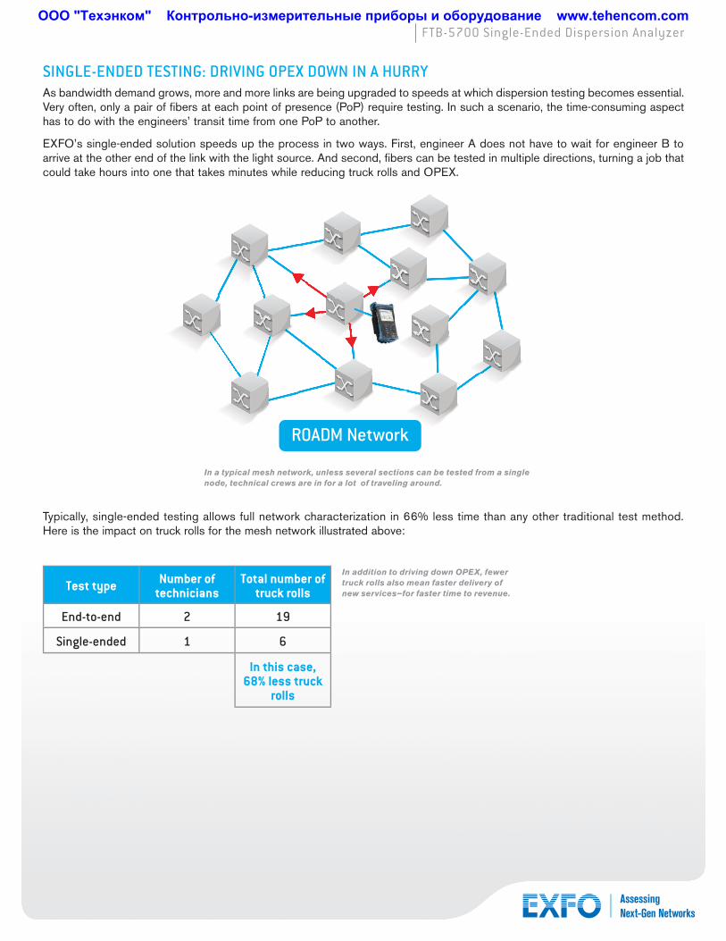
SINGLE-ENDED TESTING: DRIVING OPEX DOWN IN A HURRY As bandwidth demand grows, more and more links are being upgraded to speeds at which dispersion testing becomes essential. Very often, only a pair of fibers at each point of presence (PoP) require testing. In such a scenario, the time-consuming aspect has to do with the engineers’ transit time from one PoP to another.
EXFO’s single-ended solution speeds up the process in two ways. First, engineer A does not have to wait for engineer B to arrive at the other end of the link with the light source. And second, fibers can be tested in multiple directions, turning a job that could take hours into one that takes minutes while reducing truck rolls and OPEX.
Typically, single-ended testing allows full network characterization in 66% less time than any other traditional test method. Here is the impact on truck rolls for the mesh network illustrated above:
Test type Number of technicians
Total number of truck rolls
End-to-end 2 19
Single-ended 1 6
In this case, 68% less truck
rolls
In a typical mesh network, unless several sections can be tested from a single node, technical crews are in for a lot of traveling around.
In addition to driving down OPEX, fewer truck rolls also mean faster delivery of new services—for faster time to revenue.
ROADM Network
ООО "Техэнком" Контрольно-измерительные приборы и оборудование www.tehencom.com

FTB-5700 Single-Ended Dispersion Analyzer
FULLY AUTOMATED, WITH BUILT-IN INTELLIGENCE Featuring easy-to-read pass/fail results and providing a view of all key parameters and values on one screen, the FTB-5700’s user interface is all about field testing simplicity and efficiency.
Start with CD or PMD Testing and Upgrade to a Combined Solution Whenever Needed
Not sure if you will require CD testing in the future but need to test PMD today? The FTB-5700 lets you upgrade your dispersion testing solution as your network testing requirements evolve.
The FTB-5700 unit can be initially equipped with either the CD or PMD test features (FTB-5700-CD or FTB-5700-PMD). As your testing requirements evolve, you can then upgrade to a combined solution (FTB-5700-CD-PMD) through our service centers. This makes the purchase of this 40/100 Gbit/s-ready single-ended dispersion analyzer a truly safe and valuable investment.
ООО "Техэнком" Контрольно-измерительные приборы и оборудование www.tehencom.com

FTB-5700 Single-Ended Dispersion Analyzer
FAST-TRACK DATA POST-PROCESSING WITH FASTREPORTER SOFTWAREThe optional FastReporter software package provides you with the post-processing tools and functionalities you need to optimize your test cycles, whatever the application. Designed for offline analysis of field-acquired data, FastReporter offers a truly intuitive graphical user interface, which contributes to boosting productivity.
Flexible Reporting
Choose from various report templates, including PMD, CD and fiber characterization. Generate comprehensive cable reports in PDF, Excel or HTML format.
ENSURE CONNECTOR SUITABILITY WITH CONNECTORMAX SOFTWAREDelivering fast pass/fail assessment of connector endfaces, EXFO’s ConnectorMax Analysis Software is designed to save both time and money in the field. The industry’s first platform-based, automated inspection application, ConnectorMax eliminates guesswork, instead providing clear-cut connector endface analysis.
ConnectorMax enables field technicians to analyze defects and scratches and measure their impact on connector performance. Results are then compared against pre-programmed IEC/IPC standards or user-defined criteria, leading to accurate pass/fail verdicts established right on-site.
ConnectorMax therefore helps avoid two time- and money-consuming situations: undetected connector defects that force technicians to later return to the site, and unnecessary replacement of connectors whose slight defects are not enough to get a “fail” verdict.
› Delivers clear-cut pass/fail verdicts, eliminating guesswork in the field and saving time and money
› Lightning-fast: results in 4 seconds through simple one-touch operation
› Full test reports for future referencing
ООО "Техэнком" Контрольно-измерительные приборы и оборудование www.tehencom.com
FTB-5700 Single-Ended Dispersion Analyzer
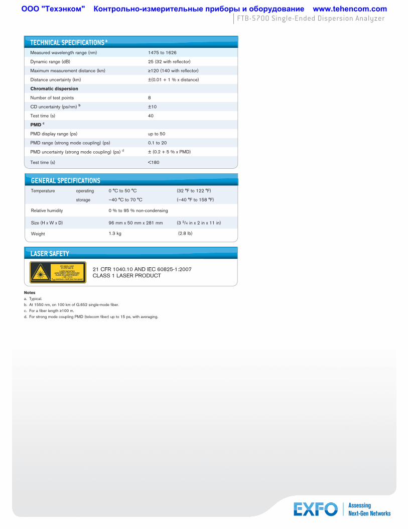
Notes
a. Typical.
b. At 1550 nm, on 100 km of G.652 single-mode fi ber.
c. For a fi ber length 100 m.
d. For strong mode coupling PMD (telecom fi ber) up to 15 ps, with averaging.
TECHNICAL SPECIFICATIONS a
Measured wavelength range (nm) 1475 to 1626
Dynamic range (dB) 25 (32 with refl ector)
Maximum measurement distance (km) 120 (140 with refl ector)
Distance uncertainty (km) ±(0.01 + 1 % x distance)
Chromatic dispersion
Number of test points 8
CD uncertainty (ps/nm) b ±10
Test time (s) 40
PMD c
PMD display range (ps) up to 50
PMD range (strong mode coupling) (ps) 0.1 to 20
PMD uncertainty (strong mode coupling) (ps) d ± (0.2 + 5 % x PMD)
Test time (s) <180
GENERAL SPECIFICATIONSTemperature operating 0 °C to 50 °C (32 °F to 122 °F)
storage —40 °C to 70 °C (—40 °F to 158 °F)
Relative humidity 0 % to 95 % non-condensing
Size (H x W x D) 96 mm x 50 mm x 281 mm (3 3/4 in x 2 in x 11 in)
Weight 1.3 kg (2.8 lb)
LASER SAFETY
21 CFR 1040.10 AND IEC 60825-1:2007CLASS 1 LASER PRODUCT
LASER RADIATIONAVOID DIRECT EYE EXPOSURE
CLASS 3R LASER PRODUCT
IEC 60825-1:200721 CFR 1040.10
λ: 650 ±10 nmPout maximum < 5mW (into free space)
ООО "Техэнком" Контрольно-измерительные приборы и оборудование www.tehencom.com

EXFO is certified ISO 9001 and attests to the quality of these products. This device complies with Part 15 of the FCC Rules. Operation is subject to the following two conditions: (1) this device may not cause harmful interference, and (2) this device must accept any interference received, including interference that may cause undesired operation. EXFO has made every effort to ensure that the information contained in this specification sheet is accurate. However, we accept no responsibility for any errors or omissions, and we reserve the right to modify design, characteristics and products at any time without obligation. Units of measurement in this document conform to SI standards and practices. In addition, all of EXFO’s manufactured products are compliant with the European Union’s WEEE directive. For more information, please visit www.EXFO.com/recycle. Contact EXFO for prices and availability or to obtain the phone number of your local EXFO distributor.
For the most recent version of this spec sheet, please go to the EXFO website at www.EXFO.com/specs.
In case of discrepancy, the Web version takes precedence over any printed literature.
EXFO Corporate Headquarters > 400 Godin Avenue, Quebec City (Quebec) G1M 2K2 CANADA | Tel.: +1 418 683-0211 | Fax: +1 418 683-2170 | [email protected]
Toll-free: +1 800 663-3936 (USA and Canada) | www.EXFO.com
EXFO America 3701 Plano Parkway, Suite 160 Plano, TX 75075 USA Tel.: +1 800 663-3936 Fax: +1 972 836-0164 EXFO Asia 151 Chin Swee Road, #03-29 Manhattan House SINGAPORE 169876 Tel.: +65 6333 8241 Fax: +65 6333 8242EXFO China 36 North, 3rd Ring Road East, Dongcheng District Beijing 100013 P. R. CHINA Tel.: + 86 10 5825 7755 Fax: +86 10 5825 7722
Room 1207, Tower C, Global Trade CenterEXFO Europe Omega Enterprise Park, Electron Way Chandlers Ford, Hampshire S053 4SE ENGLAND Tel.: +44 2380 246810 Fax: +44 2380 246801EXFO NetHawk Elektroniikkatie 2 FI-90590 Oulu, FINLAND Tel.: +358 (0)403 010 300 Fax: +358 (0)8 564 5203EXFO Service Assurance 270 Billerica Road Chelmsford, MA 01824 USA Tel.: +1 978 367-5600 Fax: +1 978 367-5700
FTB-5700 Single-Ended Dispersion Analyzer
ORDERING INFORMATION
FTB-5700-XX-XX
ModelFTB-5700-CD-PMD = Single-ended CD and PMD analyzerFTB-5700-PMD = Single-ended PMD analyzerFTB-5700-CD = Single-ended CD analyzer
ConnectorEI-EUI-28 = UPC/DIN 47256 EI-EUI-76 = UPC/HMS-10/AG EI-EUI-89 = UPC/FC narrow key EI-EUI-90 = UPC/STEI-EUI-91 = UPC/SCEI-EUI-95 = UPC/E-2000EA-EUI-28 = APC/DIN 47256EA-EUI-89 = APC/FC narrow keyEA-EUI-91 = APC/SCEA-EUI-95 = APC/E-2000
SPFTB5700.7AN © 2010 EXFO Inc. All rights reserved. 2008
Printed in Canada 10/11
Specialized TestsFor ultra-long-haul, submarine and amplifi ed network applications, EXFO also offers the FTB-5800 CD Analyzer and FTB-5500B PMD Analyzer. For these modules, the above connector choice applies, but the FLS-5834A light source is required.
Locating high-PMD fi ber spans can save a signifi cant amount of time and OPEX. Conversely, failure to do so can result in substantial costs. Building on EXFO’s proven PMD measurement expertise, the FTB-5600 module, which breaks down link assessment to pinpoint high-PMD sections, enabling cost-effective, targeted upgrades.
Example: FTB-5700-CD-PMD-EI-EUI-89
ООО "Техэнком" Контрольно-измерительные приборы и оборудование www.tehencom.com
APPLICATION NOTE 230
APPLICATION NOTE 231
Chromatic Dispersion
Chromatic dispersion (CD) has been a known fact for almost a decade now, yet testing for it on OC-192/STM-64 is not always done de facto. This may lead to major problems, especially today due to the optical distances on the core network reaching unprecedented lengths, and also in the metro environment with the birth of the mesh network topology. But now, with the current penetration of 40 Gbit/s, or OC-768/STM-256, CD is becoming an even bigger issue.
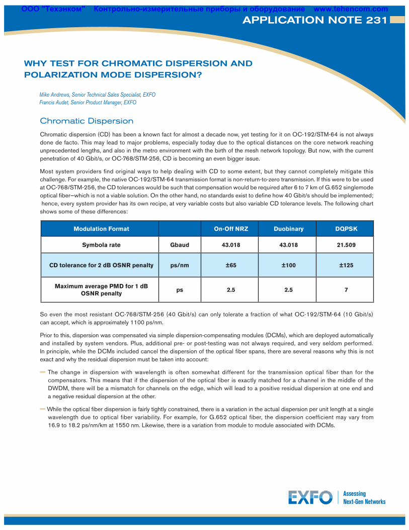
Most system providers find original ways to help dealing with CD to some extent, but they cannot completely mitigate this challenge. For example, the native OC-192/STM-64 transmission format is non-return-to-zero transmission. If this were to be used at OC-768/STM-256, the CD tolerances would be such that compensation would be required after 6 to 7 km of G.652 singlemode optical fiber—which is not a viable solution. On the other hand, no standards exist to define how 40 Gbit/s should be implemented; hence, every system provider has its own recipe, at very variable costs but also variable CD tolerance levels. The following chart shows some of these differences:
So even the most resistant OC-768/STM-256 (40 Gbit/s) can only tolerate a fraction of what OC-192/STM-64 (10 Gbit/s) can accept, which is approximately 1100 ps/nm.
Prior to this, dispersion was compensated via simple dispersion-compensating modules (DCMs), which are deployed automatically and installed by system vendors. Plus, additional pre- or post-testing was not always required, and very seldom performed. In principle, while the DCMs included cancel the dispersion of the optical fiber spans, there are several reasons why this is not exact and why the residual dispersion must be taken into account:
The change in dispersion with wavelength is often somewhat different for the transmission optical fiber than for the compensators. This means that if the dispersion of the optical fiber is exactly matched for a channel in the middle of the DWDM, there will be a mismatch for channels on the edge, which will lead to a positive residual dispersion at one end and a negative residual dispersion at the other.
While the optical fiber dispersion is fairly tightly constrained, there is a variation in the actual dispersion per unit length at a single wavelength due to optical fiber variability. For example, for G.652 optical fiber, the dispersion coefficient may vary from 16.9 to 18.2 ps/nm/km at 1550 nm. Likewise, there is a variation from module to module associated with DCMs.
Mike Andrews, Senior Technical Sales Specialist, EXFOFrancis Audet, Senior Product Manager, EXFO
WHY TEST FOR CHROMATIC DISPERSION AND POLARIZATION MODE DISPERSION?
Modulation Format On-Off NRZ Duobinary DQPSK
Symbola rate Gbaud 43.018 43.018 21.509
CD tolerance for 2 dB OSNR penalty ps/nm ±65 ±100 ±125
Maximum average PMD for 1 dB OSNR penalty
ps 2.5 2.5 7
ООО "Техэнком" Контрольно-измерительные приборы и оборудование www.tehencom.com

APPLICATION NOTE 231
DCMs are usually only available in a set of values with discrete steps between them. In contrast, installation constraints (e.g., hut positions and available rights of way) mean that the span length in a practical system is often quite different from the nominal value, leading to residual dispersion at all channel wavelengths.
In a mesh metro network where there is more than one possible route between two particular endpoints, the optical channel may be switched to an alternative route. In this case, while the residual dispersion of the primary path through the network may be acceptable, the residual dispersion of any alternative path that might be required must also be checked as it may be quite different.
Most of the installed optical fiber base, both in long-haul and metro networks, is standard singlemode optical fiber as defined by the ITU-T G.652. CD of such optical fiber can vary such as:
In addition, the aforementioned DCM also has intrinsic uncertainty and variability. Here is an example with a 80 km DCM:
As previously mentioned, DCMs are usually only available in a set of values with discrete steps between them—not per kilometer. One selects the unit which is closest to the total distance to compensate for.
So for a long-haul route of 495 km of optical fiber, DCMs will be applied for 500 km. To this, one needs to add the dispersion of all network elements, either EDFAs, fixed or reconfigurable optical add-drop multiplexers (ROADM), etc. Typical per-channel CD for such elements is in the ±30 ps/nm range.
Making the calculation for 495 km of optical fiber, plus six DCMs of 80 km and one of 20 km, plus four network elements (EDFAs), we get:
1531.12 nm minimum residual dispersion = 15.69 * 495 + 6.25 × –1278 + 4 × –30 = –341 ps/nm
1531.12 nm maximum residual dispersion = 17.10 * 495 + 6.25 × –1215 + 4 × 30 = 990.75 ps/nm
These results and those for the other wavelengths are summarized in the table below:
Maximum and minimum end-to-end residual dispersion values (worst case)
Channel Wavelength (nm) Min. (ps/nm/km) Max. (ps/nm/km)
1531.12 Very sensitive Sensitive
1546.92 Very sensitive Very sensitive
1562.23 Sensitive Sensitive
Channel Wavelength (nm) Min. (ps/nm/km) Max. (ps/nm/km)
1531.12 –341 991
1546.92 –342 994
1562.23 –361 974
Channel Wavelength (nm)80 km DCM
Min. (ps/nm/km) Max. (ps/nm/km)
1531.12 –1278 –1215
1546.92 –1355 –1288
1562.23 –1431 –1361
ООО "Техэнком" Контрольно-измерительные приборы и оборудование www.tehencom.com
APPLICATION NOTE 231
These values are very close to the acceptable limit for 10 Gbit/s transmission. The calculation can easily be redone with slightly different parameters (a few extra ROADMs in a mesh network, longer links in a long-haul network, etc.) and be over the acceptable limit for 10 Gbit/s.
But as for 40 Gbit/s, depending on the implementation, the typical acceptable CD is often less than 125 ps/nm, making this residual CD much too high for 40 Gbit/s transmission, even though each individual 80 km section may be within tolerance.
The advent of longer optical links and the birth of mesh networks put the poorly compensated residual CD very close to the danger zone for 10 Gbit/s transmission, and beyond the acceptable limit for 40 Gbit/s transmission. On the other hand, accurately testing for this parameter allows one to fine-tune each stage of compensation, as well as perform (if required) end-to-end compensation adjustments to remove excess residual dispersion.
Polarization Mode Dispersion
Polarization mode dispersion (PMD) is a consequence of certain physical properties of optical fiber that result in distortion of optical pulses. These distortions result in dispersion of the optical pulse over time, as well as a reduction in peak power. While the outcome of PMD-induced distortion is similar to CD, it is not accumulated linearly, but stochastically. This means that its value cannot be predicted from one instant to the next, but its distribution (occurrence within a predictable range) can.
Complicating factors that contribute to this unpredictability are as diverse as temperature change on optical fiber, wind load and wind turbulence on aerial optical fiber, and ice loading changing stresses on aerial optical fiber. One additional and significant constraint associated with characterizing and measuring PMD on optical fiber is the date of manufacture. In fact, optical fiber manufactured before approximately 1994 may not have been designed with PMD mitigation in mind.
Because PMD is somewhat random (stochastic) and because many legacy networks have fiber manufactured before 1994, it is important to understand its contribution to signal degradation and minimize its impact. In short, PMD is not stable or generally predictable based on any known physical characteristic of the optical fiber at the time of manufacture. It must be measured in situ, i.e., after installation.
Many transmission equipment manufacturers are working on new methods and techniques to minimize the impact of PMD on digital signals transmitted over a variety of optical fiber types. The dominant course of investigation centers on modulation methods. By carefully choosing modulation and demodulation methods, vendors hope to minimize the impact of PMD on the quality of their digital transmissions.
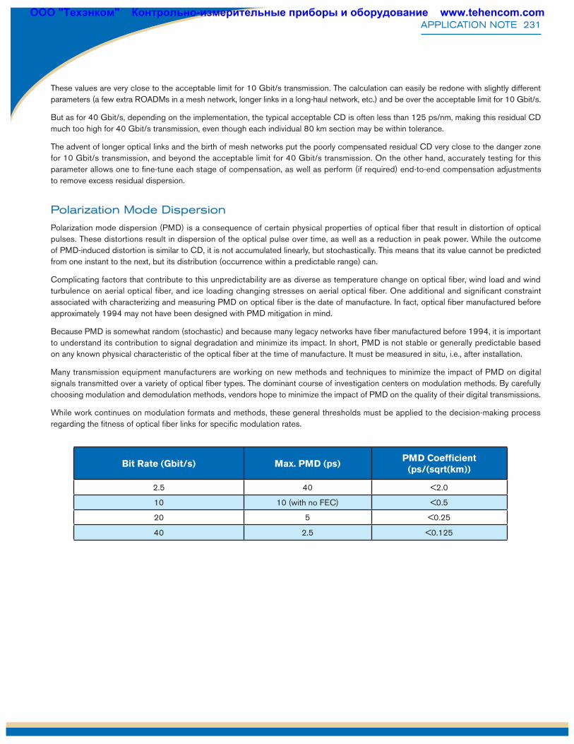
While work continues on modulation formats and methods, these general thresholds must be applied to the decision-making process regarding the fitness of optical fiber links for specific modulation rates.
Bit Rate (Gbit/s) Max. PMD (ps)PMD Coefficient
(ps/(sqrt(km))
2.5 40 <2.0
10 10 (with no FEC) <0.5
20 5 <0.25
40 2.5 <0.125
ООО "Техэнком" Контрольно-измерительные приборы и оборудование www.tehencom.com
APPNOTE231.1AN © 2010 EXFO Inc. All rights reserved. Printed in Canada 10/032008
EXFO Corporate Headquarters > 400 Godin Avenue, Quebec City (Quebec) G1M 2K2 CANADA | Tel.: +1 418 683-0211 | Fax: +1 418 683-2170 | [email protected]
Toll-free: +1 800 663-3936 (USA and Canada) | www.EXFO.com
EXFO America 3701 Plano Parkway, Suite 160 Plano, TX 75075 USA Tel.: +1 800 663-3936 Fax: +1 972 836-0164 EXFO Asia 151 Chin Swee Road, #03-29 Manhattan House SINGAPORE 169876 Tel.: +65 6333 8241 Fax: +65 6333 8242EXFO China Tower C, Beijing Global Trade Center, Room 1207 Beijing 100013 P. R. CHINA Tel.: + 86 10 5825 7755 Fax: +86 10 5825 7722 36 North Third Ring Road East, Dongcheng DistrictEXFO Europe Omega Enterprise Park, Electron Way Chandlers Ford, Hampshire S053 4SE ENGLAND Tel.: +44 2380 246810 Fax: +44 2380 246801EXFO Service Assurance 285 Mill Road Chelmsford, MA 01824 USA Tel.: +1 978 367-5600 Fax: +1 978 367-5700
APPLICATION NOTE 231
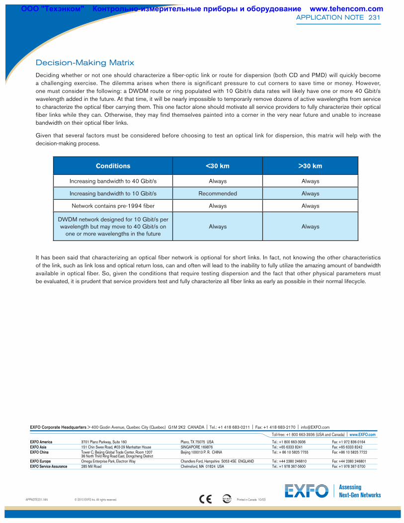
Decision-Making Matrix
Deciding whether or not one should characterize a fiber-optic link or route for dispersion (both CD and PMD) will quickly become a challenging exercise. The dilemma arises when there is significant pressure to cut corners to save time or money. However, one must consider the following: a DWDM route or ring populated with 10 Gbit/s data rates will likely have one or more 40 Gbit/s wavelength added in the future. At that time, it will be nearly impossible to temporarily remove dozens of active wavelengths from service to characterize the optical fiber carrying them. This one factor alone should motivate all service providers to fully characterize their optical fiber links while they can. Otherwise, they may find themselves painted into a corner in the very near future and unable to increase bandwidth on their optical fiber links.
Given that several factors must be considered before choosing to test an optical link for dispersion, this matrix will help with the decision-making process.
It has been said that characterizing an optical fiber network is optional for short links. In fact, not knowing the other characteristics of the link, such as link loss and optical return loss, can and often will lead to the inability to fully utilize the amazing amount of bandwidth available in optical fiber. So, given the conditions that require testing dispersion and the fact that other physical parameters must be evaluated, it is prudent that service providers test and fully characterize all fiber links as early as possible in their normal lifecycle.
Conditions <30 km >30 km
Increasing bandwidth to 40 Gbit/s Always Always
Increasing bandwidth to 10 Gbit/s Recommended Always
Network contains pre-1994 fiber Always Always
DWDM network designed for 10 Gbit/s per wavelength but may move to 40 Gbit/s on
one or more wavelengths in the futureAlways Always
ООО "Техэнком" Контрольно-измерительные приборы и оборудование www.tehencom.com


![Zgb dgb] - saha-skazka.tvoysadik.ru](https://static.fdocuments.net/doc/165x107/61c511e6eefbc96698429df2/zgb-dgb-saha-.jpg)