ZF* R S COMPRESSORS USING R407A, R407F, R448A L T A · PDF fileC7.19.2/0813-1016/E 2/14 1...
14
C7.19.2/0813-1016/E 1/14 Date of last update: Oct-16 Ref: C7.19.2/0813-1016/E Application Engineering Europe ZF* REFRIGERATION SCROLL™ COMPRESSORS USING R407A, R407F, R448A OR R449A IN LOW TEMPERATURE APPLICATIONS ZF* Refrigeration Scroll™ Compressors Using R407A, R407F, R448A or R449A in Low Temperature Applications 1 1 Introduction ...................................................................................................................................................... 2 2 Liquid injection ................................................................................................................................................. 2 2.1 DTC valve connections ............................................................................................................................ 3 2.2 DTC valve installation .............................................................................................................................. 5 3 Vapour injection (EVI = Economized Vapour Injection) ................................................................................... 5 3.1 Principle of operation ............................................................................................................................... 6 3.2 Subcooler selection and application ........................................................................................................ 7 3.3 Liquid receiver ......................................................................................................................................... 9 3.4 Line lengths and insulation ....................................................................................................................10 4 Vapour injection + liquid injection (wet vapour injection) ...............................................................................10 5 Discharge temperature protection .................................................................................................................12 5.1 Discharge line thermostat specifications ...............................................................................................12 5.2 Discharge line thermostat installation ....................................................................................................13 DISCLAIMER ..............................................................................................................................................................14
Transcript of ZF* R S COMPRESSORS USING R407A, R407F, R448A L T A · PDF fileC7.19.2/0813-1016/E 2/14 1...

C7.19.2/0813-1016/E 1/14
Date of last update: Oct-16 Ref: C7.19.2/0813-1016/E
Application Engineering Europe
ZF* REFRIGERATION SCROLL™ COMPRESSORS
USING R407A, R407F, R448A OR R449A IN LOW TEMPERATURE
APPLICATIONS
ZF* Refrigeration Scroll™ Compressors Using R407A, R407F, R448A or R449A in Low Temperature Applications 1
1 Introduction ...................................................................................................................................................... 2
2 Liquid injection ................................................................................................................................................. 2
2.1 DTC valve connections ............................................................................................................................ 3
2.2 DTC valve installation .............................................................................................................................. 5
3 Vapour injection (EVI = Economized Vapour Injection) ................................................................................... 5
3.1 Principle of operation ............................................................................................................................... 6
3.2 Subcooler selection and application ........................................................................................................ 7
3.3 Liquid receiver ......................................................................................................................................... 9
3.4 Line lengths and insulation .................................................................................................................... 10
4 Vapour injection + liquid injection (wet vapour injection) ............................................................................... 10
5 Discharge temperature protection ................................................................................................................. 12
5.1 Discharge line thermostat specifications ............................................................................................... 12
5.2 Discharge line thermostat installation .................................................................................................... 13
DISCLAIMER .............................................................................................................................................................. 14
C7.19.2/0813-1016/E 2/14
1 Introduction
The low temperature application of ZF* Copeland Scroll™ compressors with refrigerants R407A, R407F, R448A or R449A requires the use of dedicated injection technologies in order to provide excellent compressor efficiencies and to keep the operation within safe limits.
Depending on the ZF* Copeland Scroll compressor family, the following injection systems can be used:
Compressor family Liquid
injection Vapour
injection Vapour + liquid
injection
ZF06K4E to ZF18K4E X
ZF(D)13KVE to ZF(D)25KVE
X X
ZF25K5E to ZF49K5E ZFD41K5E
X X X
Table 1
The ZF*K4E range of compressors would need to be equipped with liquid injection by the usage of a DTC valve.
Compressor models ZF(D)13KVE to ZF(D)25KVE are vapour injection only. Liquid injection alone is not possible.
Compressor models ZF25K5E to ZF49K5E and ZFD41K5E are designed and applicable for both liquid injection and vapour injection (EVI).
For compressor models ZF(D)13KVE to ZF(D)25KVE, ZFD41K5E and ZF25K5E to ZF49K5E applied with vapour injection, the operation envelope can be increased by the usage of wet vapour injection. Wet vapour injection is a combination of vapour and liquid injection at the same time and can be used in order to operate the scroll compressors in a larger application envelope.
For corresponding operation envelopes, please refer to the compressor technical data, such as Emerson Select Software.
NOTE: For all ZF* compressor types in low temperature applications with R407A, R407F, R448A or R449A, the installation of liquid or vapour injection is mandatory. All corresponding operating envelopes are based on the use of liquid or vapour injection.
Special care needs to be taken to ensure that the dedicated discharge temperature thermostats (DLT) installed are for use with R407A, R407F, R448A or R449A.
See documented operating envelopes in the compressor technical data (Select Software). The Select software can be downloaded from www.emersonclimate.eu under quick links/product selection software/Copeland and Alco selection software/downloads.
2 Liquid injection
Liquid injection for ZF*K4E and ZF*K5E scroll compressors is mandatory to keep discharge gas temperatures within safe limits.
The following ZF* liquid injection models can be used with R407A, R407F, R448A or R449A:
ZF06-18K4E-TFD
Components for liquid injection:
8409496 Discharge line thermostat kit 130°C, incl. clip 5/8"
8414403 Liquid injection DTC 120°C – 11/16" kit
including DTC valve, O-ring gasket and protection cap
Retrofit R404A systems with ZF06-18K4E and R407A, R407F, R448A or R449A:
Please install:
8414403 Liquid injection DTC kit 120°C – 11/16"
8409496 Discharge line thermostat kit 130°C, incl. clip 5/8"

C7.19.2/0813-1016/E 3/14
The use of existing R404A liquid injection components is possible, but not optimized for R407A, R407F, R448A, R449A.
8563054 Liquid injection DTC kit 90°C
8536083 Gasket DTC valve 90°C
2981196 Discharge line thermostat kit 105°C, incl. clip 5/8"
ZF25K5E-TFD
Components for liquid injection:
8409496 Discharge line thermostat kit 130°C, incl. clip 5/8"
8414390 Liquid injection DTC kit 120°C – 1"
including DTC valve, Teflon gasket and protection cap
ZF34-49K5E, ZFD41K5E TFD
Components for liquid injection:
8615262 Discharge line thermostat kit 130°C, incl. clip 7/8"
8414390 Liquid injection DTC kit 120°C – 1"
including DTC valve, Teflon gasket and protection cap
Liquid injection is achieved by means of a Discharge Temperature Control (DTC) valve. The DTC valve is equipped with a custom bulb profile, which must be installed in the top well of the compressor sensing the temperature closest to the discharge port. The DTC valve only allows injection when cooling is needed and in the required amount.
The use of an external discharge thermostat is mandatory for all compressor models ZF06K4E to ZF18K4E, ZF25K5E to ZF49K5E and ZF49K5E. For all compressor models ZF*K4E and ZF*K5E, the discharge thermostat is included in the standard delivery of the compressor.
2.1 DTC valve connections
Figure 1: Liquid injection with DTC valve

C7.19.2/0813-1016/E 4/14
To prevent a partial or full blockage at the injection port caused by shavings, foreign bodies, etc. a filter dryer should be installed in the liquid line prior to the DTC valve inlet.
8414403 Liquid injection DTC kit 120°C – 11/16"
o 3/8" (9.5 mm) braze connection on the liquid inlet of the DTC valve
o 11/16" – 16 UN connection, compressor injection port
o 3/8" (9.5 mm) braze connection on the liquid inlet of the DTC valve
o 11/16" – 16 UN connection, compressor injection port
Recommended tightening torque 24-27 Nm
Figure 2: Liquid injection DTC valve 120°C – 11/16"
8414390 Liquid injection DTC kit 120°C – 1"
o 3/8" (9.5 mm) braze connection on the liquid inlet of the DTC valve
o 1" – 14 UNS connection, compressor injection port
Recommended tightening torque 29-34 Nm
Figure 3: Liquid injection DTC valve 120°C – 1"
C7.19.2/0813-1016/E 5/14
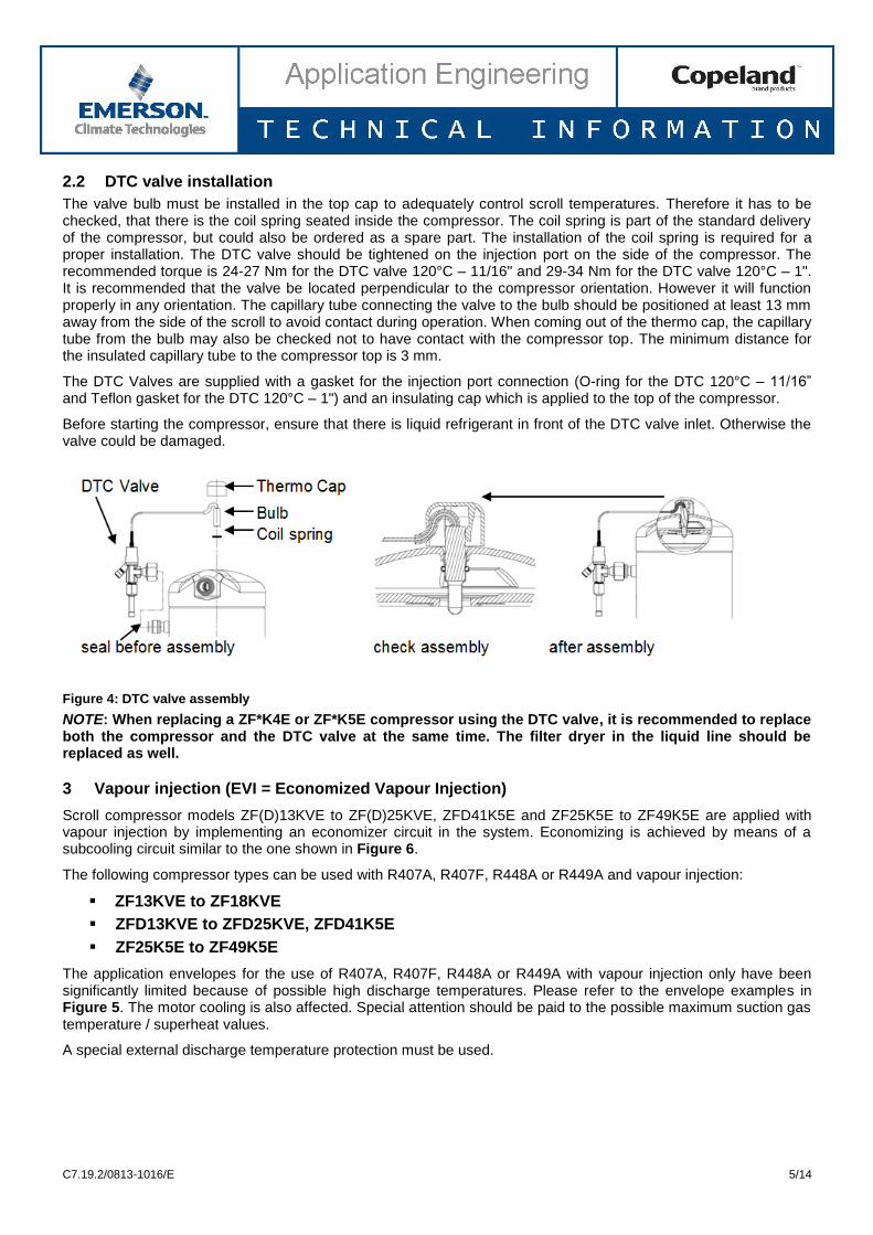
2.2 DTC valve installation
The valve bulb must be installed in the top cap to adequately control scroll temperatures. Therefore it has to be checked, that there is the coil spring seated inside the compressor. The coil spring is part of the standard delivery of the compressor, but could also be ordered as a spare part. The installation of the coil spring is required for a proper installation. The DTC valve should be tightened on the injection port on the side of the compressor. The recommended torque is 24-27 Nm for the DTC valve 120°C – 11/16" and 29-34 Nm for the DTC valve 120°C – 1". It is recommended that the valve be located perpendicular to the compressor orientation. However it will function properly in any orientation. The capillary tube connecting the valve to the bulb should be positioned at least 13 mm away from the side of the scroll to avoid contact during operation. When coming out of the thermo cap, the capillary tube from the bulb may also be checked not to have contact with the compressor top. The minimum distance for the insulated capillary tube to the compressor top is 3 mm.
The DTC Valves are supplied with a gasket for the injection port connection (O-ring for the DTC 120°C – 11/16” and Teflon gasket for the DTC 120°C – 1") and an insulating cap which is applied to the top of the compressor.
Before starting the compressor, ensure that there is liquid refrigerant in front of the DTC valve inlet. Otherwise the valve could be damaged.
Figure 4: DTC valve assembly
NOTE: When replacing a ZF*K4E or ZF*K5E compressor using the DTC valve, it is recommended to replace both the compressor and the DTC valve at the same time. The filter dryer in the liquid line should be replaced as well.
3 Vapour injection (EVI = Economized Vapour Injection)
Scroll compressor models ZF(D)13KVE to ZF(D)25KVE, ZFD41K5E and ZF25K5E to ZF49K5E are applied with vapour injection by implementing an economizer circuit in the system. Economizing is achieved by means of a subcooling circuit similar to the one shown in Figure 6.
The following compressor types can be used with R407A, R407F, R448A or R449A and vapour injection:
ZF13KVE to ZF18KVE
ZFD13KVE to ZFD25KVE, ZFD41K5E
ZF25K5E to ZF49K5E
The application envelopes for the use of R407A, R407F, R448A or R449A with vapour injection only have been significantly limited because of possible high discharge temperatures. Please refer to the envelope examples in Figure 5. The motor cooling is also affected. Special attention should be paid to the possible maximum suction gas temperature / superheat values.
A special external discharge temperature protection must be used.

C7.19.2/0813-1016/E 6/14
Figure 5: Operating envelopes – Vapour injection only
NOTE: The application envelopes for R407A, R407F, R448A, R449A can be enlarged with the combination of vapour injection and liquid injection. See also Chapter 4 "Wet vapour injection".
NOTE: The use of the existing R404A discharge line thermostat is NOT possible. R407A, R407F, R448A and R449A applications require the 130°C discharge gas thermostat.
ZF(D)13-18KVE
Components for vapour injection:
8409496 Discharge line thermostat kit 130°C, incl. clamp 5/8"
ZF34-49K5E, ZF(D)25K5E, ZFD41K5E
Components for vapour injection:
8615262 Discharge line thermostat kit 130°C, incl. clamp 7/8"
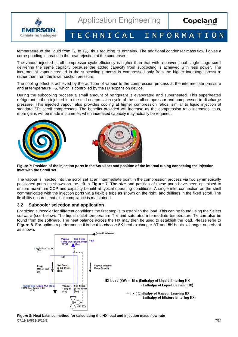
3.1 Principle of operation
Vapour-injected scroll compressors make use of an economizer with the vapour compression cycle. This cycle offers the advantages of more cooling capacity and a better COP than with a conventional cycle. The improvement of both the capacity and the COP is proportional to the temperature lift and this technology offers best results at low evaporating temperatures where capacity and efficiency are most needed. It is usually possible to specify a smaller displacement compressor for a given cooling load.
Figure 6: Circuit diagrams showing the main circuit, the mass flow rate m, the economizer circuit and the mass flow rate i
A portion of the condensed liquid i is expanded through an expansion valve into a counterflow brazed-plate heat exchanger (HX), which acts as a subcooler. The superheated vapour is then injected into an intermediate vapour injection port in the scroll compressor. The additional subcooling increases the evaporator capacity by reducing the
C7.19.2/0813-1016/E 7/14
temperature of the liquid from TLI to TLO, thus reducing its enthalpy. The additional condenser mass flow i gives a corresponding increase in the heat rejection at the condenser.
The vapour-injected scroll compressor cycle efficiency is higher than that with a conventional single-stage scroll delivering the same capacity because the added capacity from subcooling is achieved with less power. The incremental vapour created in the subcooling process is compressed only from the higher interstage pressure rather than from the lower suction pressure.
The cooling effect is achieved by the addition of vapour to the compression process at the intermediate pressure and at temperature TVO which is controlled by the HX expansion device.
During the subcooling process a small amount of refrigerant is evaporated and superheated. This superheated refrigerant is then injected into the mid compression cycle of the scroll compressor and compressed to discharge pressure. This injected vapour also provides cooling at higher compression ratios, similar to liquid injection of standard ZF* scroll compressors. The benefits provided will increase as the compression ratio increases, thus, more gains will be made in summer, when increased capacity may actually be required.
Figure 7: Position of the injection ports in the Scroll set and position of the internal tubing connecting the injection inlet with the Scroll set
The vapour is injected into the scroll set at an intermediate point in the compression process via two symmetrically positioned ports as shown on the left in Figure 7. The size and position of these ports have been optimised to ensure maximum COP and capacity benefit at typical operating conditions. A single inlet connection on the shell communicates with the injection ports via a flexible tube as shown on the right, and drillings in the fixed scroll. The flexibility ensures that axial compliance is maintained.
3.2 Subcooler selection and application
For sizing subcooler for different conditions the first step is to establish the load. This can be found using the Select software (see below). The liquid outlet temperature TLO and saturated intermediate temperature TSI can also be found from the software. The heat balance across the HX may then be used to establish the load. Please refer to Figure 8. For optimum performance it is best to choose 5K heat exchanger ΔT and 5K heat exchanger superheat as shown.
Figure 8: Heat balance method for calculating the HX load and injection mass flow rate
C7.19.2/0813-1016/E 8/14
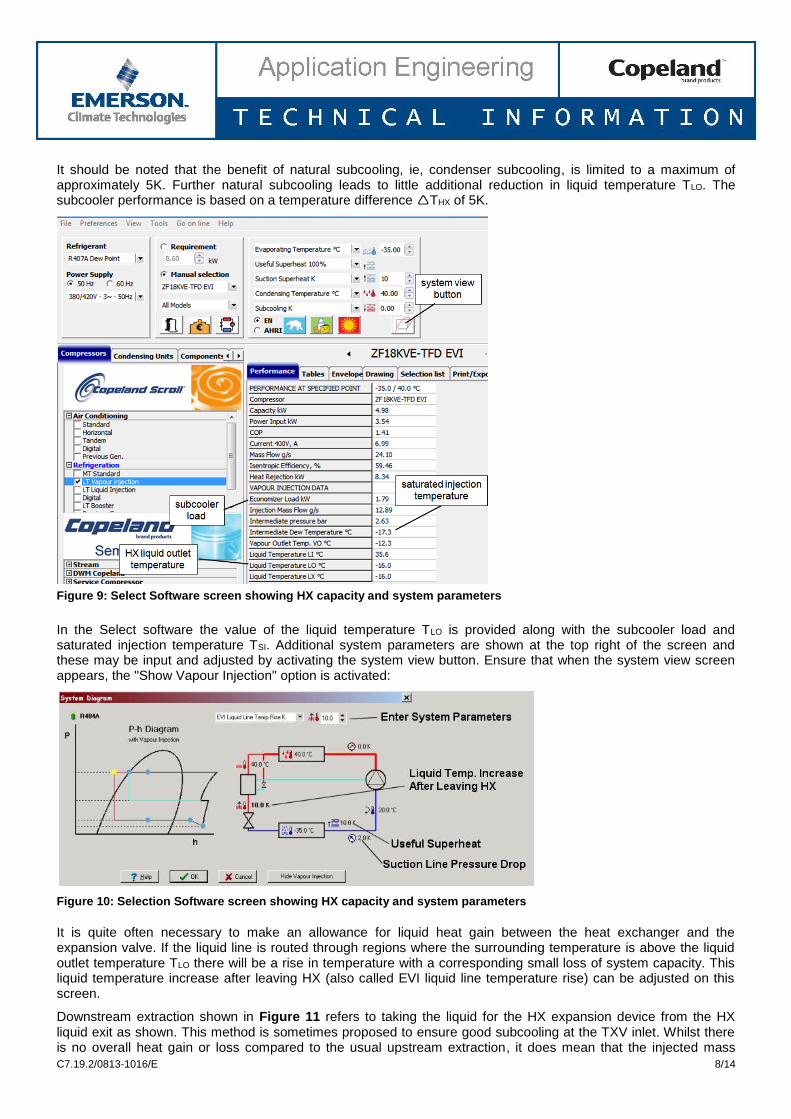
It should be noted that the benefit of natural subcooling, ie, condenser subcooling, is limited to a maximum of approximately 5K. Further natural subcooling leads to little additional reduction in liquid temperature TLO. The subcooler performance is based on a temperature difference THX of 5K.
Figure 9: Select Software screen showing HX capacity and system parameters
In the Select software the value of the liquid temperature TLO is provided along with the subcooler load and saturated injection temperature TSI. Additional system parameters are shown at the top right of the screen and these may be input and adjusted by activating the system view button. Ensure that when the system view screen appears, the "Show Vapour Injection" option is activated:
Figure 10: Selection Software screen showing HX capacity and system parameters
It is quite often necessary to make an allowance for liquid heat gain between the heat exchanger and the expansion valve. If the liquid line is routed through regions where the surrounding temperature is above the liquid outlet temperature TLO there will be a rise in temperature with a corresponding small loss of system capacity. This liquid temperature increase after leaving HX (also called EVI liquid line temperature rise) can be adjusted on this screen.
Downstream extraction shown in Figure 11 refers to taking the liquid for the HX expansion device from the HX liquid exit as shown. This method is sometimes proposed to ensure good subcooling at the TXV inlet. Whilst there is no overall heat gain or loss compared to the usual upstream extraction, it does mean that the injected mass

C7.19.2/0813-1016/E 9/14
flow i is passing through the HX twice and incurring extra pressure drop on the liquid cooling side. This may result in the need for a larger HX. Also downstream extraction requires more connections and tubing on the subcooled liquid side all of which need to be insulated to ensure minimal heat gain. For these reasons downstream extraction is less preferable than upstream shown in Figure 11.
Figure 11: Liquid extraction (a) Upstream (recommended) (b) Downstream (not recommended)
The subcooler HX must be installed vertically with the vapour entry at the bottom. The expansion valve should be connected at a distance between 150 mm and 200 mm from the vapour entry and at a position not lower than the inlet connection.
Figure 12: Position of the expansion valve and bulb when using a plate heat exchanger
Where a thermostatic valve is used the bulb of the expansion valve should be positioned 400 to 600 mm from the vapour outlet preferably after a bend and on the inside as shown on the left in Figure 12. The position of the bulb relative to the section of the tube is illustrated. It should not be attached underneath the tube. External equalisation is not essential. The tubing between the expansion valve and the HX entry may either be straight or include a bend as shown on the right in Figure 12.
For multiple compressor systems an electronic expansion valve is recommended.
3.3 Liquid receiver
A liquid receiver may be necessary to accommodate charge variations over the operating condition range. It should always be fitted in the condenser outlet liquid line and not in the heat exchanger outlet liquid line. This is because vapour phase may be present in a receiver and this is only possible with saturated liquid.
Figure 13: Where NOT to place the liquid receiver
C7.19.2/0813-1016/E 10/14
3.4 Line lengths and insulation
The liquid line from the HX to the expansion valve(s) needs to be well insulated. Vapour lines between both expansion devices and the heat exchangers (evaporator and subcooler) need to be kept as short as practical and well insulated. The subcooler HX should also be insulated. All lines shown in blue colour in the circuit diagrams require insulation.
Liquid line temperature rise: In many installations where the compressor(s) is (are) situated away from the evaporator(s) the liquid temperature will increase during its travel from the HX to the evaporator. Even with insulated lines this temperature rise can result in a small loss of capacity. The heat gain may be estimated by calculation methods and a typical value for liquid temperature rise is approximately. 0.7K over 10 meters when passing through areas at 20°C air temperature. To adjust capacity for this effect in the Select software go to "System View => Show Vapour Injection" and enter a value for liquid temperature rise.
4 Vapour injection + liquid injection (wet vapour injection)
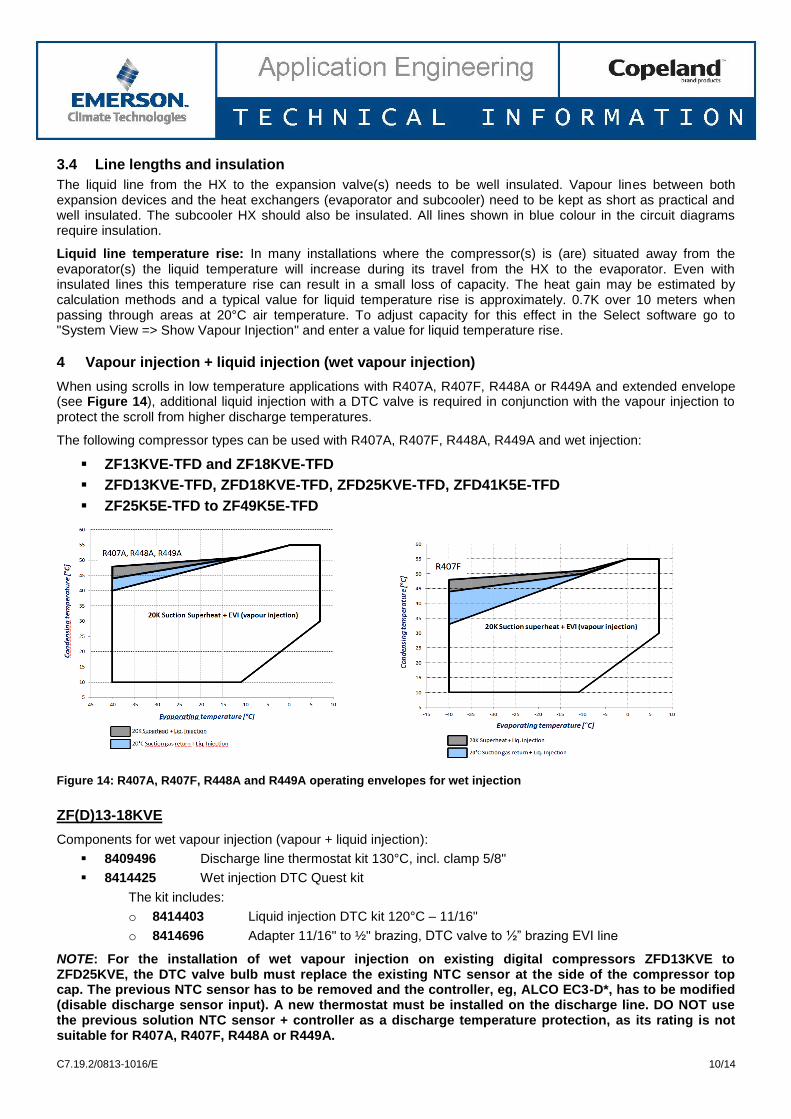
When using scrolls in low temperature applications with R407A, R407F, R448A or R449A and extended envelope (see Figure 14), additional liquid injection with a DTC valve is required in conjunction with the vapour injection to protect the scroll from higher discharge temperatures.
The following compressor types can be used with R407A, R407F, R448A, R449A and wet injection:
ZF13KVE-TFD and ZF18KVE-TFD
ZFD13KVE-TFD, ZFD18KVE-TFD, ZFD25KVE-TFD, ZFD41K5E-TFD
ZF25K5E-TFD to ZF49K5E-TFD
Figure 14: R407A, R407F, R448A and R449A operating envelopes for wet injection
ZF(D)13-18KVE
Components for wet vapour injection (vapour + liquid injection):
8409496 Discharge line thermostat kit 130°C, incl. clamp 5/8"
8414425 Wet injection DTC Quest kit
The kit includes:
o 8414403 Liquid injection DTC kit 120°C – 11/16"
o 8414696 Adapter 11/16" to ½" brazing, DTC valve to ½” brazing EVI line
NOTE: For the installation of wet vapour injection on existing digital compressors ZFD13KVE to ZFD25KVE, the DTC valve bulb must replace the existing NTC sensor at the side of the compressor top cap. The previous NTC sensor has to be removed and the controller, eg, ALCO EC3-D*, has to be modified (disable discharge sensor input). A new thermostat must be installed on the discharge line. DO NOT use the previous solution NTC sensor + controller as a discharge temperature protection, as its rating is not suitable for R407A, R407F, R448A or R449A.
C7.19.2/0813-1016/E 11/14
ZF25K5E, ZFD25KVE
Components for wet vapour injection (vapour + liquid injection):
8409496 Discharge line thermostat kit 130°C, incl. clamp 5/8"
8414436 Wet vapour injection DTC Summit + Stretch Quest kit
The kit includes:
o 8414390 Liquid injection DTC kit 1", incl. gasket
o 2856550 Adapter DTC valve to ½" line, 1" 14UN Rotalock to ½" inner diameter brazing
o 8622480 Adapter kit incl. gasket, injection port 1" UNS 14 to ½" brazing
ZF34-49K5E-TFD, ZFD41K5E
Components for wet vapour injection (vapour + liquid injection):
8615262 Discharge line thermostat kit 130°C, incl. clamp 7/8"
8414436 Wet vapour injection DTC Summit + Stretch Quest kit
The kit includes:
o 8414390 Liquid injection DTC kit 1", incl. gasket
o 2856550 Adapter DTC valve to ½" line, 1" 14UNS rotalock to ½" inner diameter brazing
o 8622480 Adapter kit incl. gasket, injection port 1" UNS 14 to ½" brazing
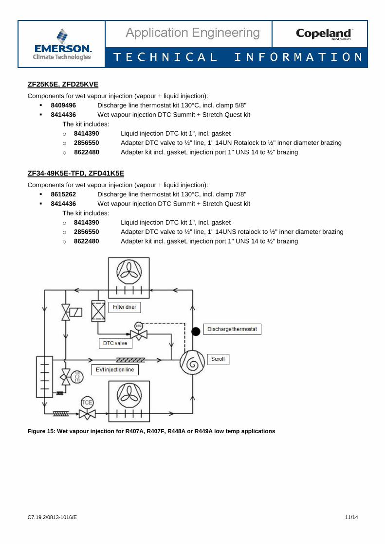
Figure 15: Wet vapour injection for R407A, R407F, R448A or R449A low temp applications

C7.19.2/0813-1016/E 12/14
Figure 16: Installation of wet vapour injection for R407A, R407F, R448A or R449A low temp applications, example with ½" EVI vapour injection line
5 Discharge temperature protection
When using R407A, R407F, R448A or R449A in low temperature applications, the discharge temperature must be observed. Special care should be taken for the usage of R407A, R407F, R448A and R449A dedicated discharge line thermostats. Excessive discharge gas temperatures can lead to premature compressor failure.
The discharge line thermostat is required in the compressor control circuit. The recommended thermostats have a cut-out setting that will ensure a discharge line temperature below the maximum allowed limit. The discharge line thermostat should be installed approximately 120 mm from the discharge tube outlet.
For correct function, it is recommended that the thermostat should be insulated to protect it from a direct air stream. Kits have been set up to include the thermostat, a clamp and installation instructions.
Thermostats for compressor models ZF06K4E to ZR18K4E, ZF25K5E, ZF13KVE, ZF18KVE and ZFD13KVE to ZFD25KVE must be used with 5/8" (15.8 mm) outside diameter discharge lines to ensure proper thermal transfer and temperature control. Compressor models ZF34K5E to ZF49K5E require a discharge line thermostat with 7/8" (22.2 mm) outside diameter.
The discharge line thermostat will work with either 120 or 240 volt supply.
High discharge temperature protection should always be fitted to each compressor. This ensures that the compressor cannot overheat in the event of loss of liquid or vapour injection cooling.
5.1 Discharge line thermostat specifications
ZF06-18K4E, ZF(D)13-18KVE (R404A, R407A, R407F, R448A, R449A)
8409496 Discharge line thermostat kit 130°C, incl. clamp
o 5/8" (15.8 mm) clamp diameter
o Open 129°C ± 4K

C7.19.2/0813-1016/E 13/14
ZF25K5E, ZFD25KVE (R404A, R407A, R407F, R448A, R449A)
8409496 Discharge line thermostat kit 130°C, incl. clamp
o 5/8" (15.8 mm) clamp diameter
o Open 129°C ± 4K
ZF34-49K5E, ZFD41K5E (R404A, R407A, R407F, R448A, R449A)
8615262 discharge line thermostat kit 130°C, incl. clamp
o 7/8" (22.2 mm) clamp diameter
o Open 129°C ± 4K
5.2 Discharge line thermostat installation
Install the discharge line thermostat on the discharge tube 120 mm from top cap.
Snap the retainer clip over the tube and onto the thermostat.
The thermostat should be placed on the discharge tube so that its body is in upward position on a horizontal tube installation.
Ensure that the thermostat is not tilted.
The wire must not be in contact with the top cap of the compressor or the discharge tube. Care should be taken to route wires so that they do not come into contact with sharp objects.
To avoid any impact on tripping temperature by the ambient, the discharge line thermostat must be insulated.
Wrap thermal insulation around the pipe left and right of the thermostat and secure it with plastic straps.
Wrap a second layer of insulation around the first one and around the thermostat, and secure it with plastic straps.
Figure 17: Installation recommendations for the discharge temperature protection

C7.19.2/0813-1016/E 14/14
DISCLAIMER
1. The contents of this publication are presented for informational purposes only and are not to be construed as warranties or guarantees, express or implied, regarding the products or services described herein or their use or applicability.
2. Emerson Climate Technologies GmbH and/or its affiliates (collectively "Emerson"), as applicable, reserve the right to modify the design or specifications of such products at any time without notice.
3. Emerson does not assume responsibility for the selection, use or maintenance of any product. Responsibility for proper selection, use and maintenance of any Emerson product remains solely with the purchaser or end user.
4. Emerson does not assume responsibility for possible typographic errors contained in this publication.