Zeus General Care Trunking - Pneumatech MGS home ... General Care Trunking Page 4 Installation,...
10
Zeus General Care Trunking Medical Supply Units Installation Instructions
Transcript of Zeus General Care Trunking - Pneumatech MGS home ... General Care Trunking Page 4 Installation,...

Zeus General Care TrunkingMedical Supply Units
Installation Instructions

Zeus General Care Trunking Page 2
Installation, Operation and Maintenance Manual
Published by Pneumatech Medical Gas Solutions
All possible care has been taken in the preparation of this publication, but Pneumatech Medical Gas Solutions accepts no liability for any inaccuracies that may be found.
Pneumatech Medical Gas Solutions reserves the right to make changes without notice both to this publication and to the product which it describes.
Copyright © 2015 Atlas Copco All rights reserved.
No part of this publication may be reproduced, transmitted, transcribed, or stored in a retrieval system or translated into any human or computer language in any form or by any means without the prior permission of Pneumatech Medi-cal Gas Solutions.
ImportantPersonnel must make themselves familiar with the contents of this manual and the function of the unit before installing, operating or maintaining any trunking system.
Information contained in this manual is correct at the date of publication. The policy of Pneumatech Medical Gas Solutions is one of continuous product improvement. Pneumatech Medical Gas Solutions reserves the right to make changes that may affect instructions in this manual without prior notice.
For any enquiry regarding the servicing or repair of this device, contact the nearest accredited Pneumatech Medical Gas Solutions agent, or communicate directly with:
Pneumatech Medical Gas SolutionsUnit 18 Nuffield CentrumNuffield WayAbingdonOxfordshireOX14 1RLUK
http://www.p-mgs.com
Sales Spares [email protected] [email protected] [email protected]
Any complaints about the products or services provided by Pneumatech Medical Gas Solutions, please give as much of the following information as possible:
Product Part NumberSerial NumberApproximate date of purchaseApparent fault.

Installation, Operation and Maintenance Manual
Zeus General Care Trunking Page 3
Table of Contents
2 Safety, Storage and Handling
2 Environmental Transport, Storage and Operating Conditions
3 Description
4 Wall Plate Installation
5 Figure 1 - Trunking mounting height diagram
5 Figure 2 - Mounting plate position diagram
6 Figure 3 - Preparation of trunking joints diagram
6 Figure 4 - Trunking joining diagram
6 Figure 5 - Backplate screw hole position diagram
7 Downdrop installation (if required)
8 Figure 6 - Downdrop backplate diagram
8 Figure 7 - Downdrop cable routing diagram
9 Figure 8 - Electrical installation diagram
9 Figure 9 - Downdrop earth bonding diagram
9 Figure 10 - Securing downdrop lid diagram
Safety, Storage and Handling Data
CAUTION!Do not use oil or grease on any terminal units or pipework, for any reason. This could lead to a FIRE or an EXPLOSION. Only use approved OXYGEN COMPATIBLE lubricants, which can be obtained from Pneumatech MGS.
WARNING!Before carrying out any maintenance on low voltage electrical services within the trunking, ensure that the circuits behind all fascias that are to be ac-cessed are de-energised and isolated first.
The trunking carcass requires no special maintenance procedures, other than if it becomes damaged. Individual fascia plates are removable by peeling back the plas-tic cover strip at the top of the fascia and removing the screws. Fascia plates are split between extra low voltage, low voltage and gas services. This enables maintenance to be carried out without disturbance to other services. Circuit diagrams, component parts lists and descriptions are all available on request. The following symbols apply to this product and are used in these instructions and on the product in question. The meanings of these symbols are as specified below: -
Environmental Transport and Storage Conditions & Operating Conditions
Min ambient temperature - 0 degrees CelsiusMax ambient temperature - 40 degrees CelsiusMin relative humidity (non-condensing) - 10%Max relative humidity (non-condensing) - 95%Atmospheric pressure range - 70-110 kPa
- Read instructions
- Temperature range
- Date of manufacture (Year/Month) - Alternating current
- Protected earth connection
- Type B applied part (EN 60601-1:1990)
- Dangerous voltage - No suitable for mounting on normally flammable surfaces
(EN 60589-1)

Zeus General Care Trunking Page 4
Installation, Operation and Maintenance Manual
Cleaning
The trunking and components should be wiped over with a damp cloth frequently to remove any dust or foreign substances.
Environmental Protection
Discard the unit and/or components in any standard refuse facility. The unit does not contain any hazardous substances. Electromagnetic Interference
Ensure any input and data cables are physically separated from other mains and data cables. Pneumatech MGS Zeus Trunking with integral lighting units fitted is not suitable for use with equipment that may be affected by electromagnetic interference. Electromyograms, Electroencephalograms and Electrocardiograms should not be used in conjunction Pneumatech MGS Zeus Trunking if integral lighting is fitted.
Electrical Details
WARNING...It is necessary to check the integrity of the power source for safety at regular intervals. These checks should be carried out annually and replacement power supplies used is necessary.
Power source
Mains operated using 110/230V, 50/60Hz, alternating current. Please see labelling inside unit for correct voltage.
Type of protection against electric shock
Class 1 (Mains supplied equipment using a protected earth).
Mode of operation
Continuous (equipment may be left switched on indefinitely).
Degree of protection against ingress of liquids
IPX0 (Not protected).
Degree of mobility Permanently installed (This unit is electrically connected by permanent means).
Degree of protection
Type B (no Applied Part or with and Applied Part not designed to meet F type (floating) requirements).
Degree of protection against flammable anaesthetic mixtures
Not protected (not suitable for use with flammable gases).
Description
The Zeus Bedspace Management System is designed to provide a safe, efficient means of delivering services to patients/staff in general ward, recovery, examination & isolation areas. The lighting units are designed to provide illumination for both reading and general area illumination. Lighting is designed to comply with the requirements of CIBSE LG2 “Hospitals and Healthcare Buildings”. LG2 is a recommendation which is produced by the ‘Chartered Institute of Building Services Engineers’ (CIBSE) in the U.K. LG2 is a comprehensive in-depth guide, which has been developed over many years, incorporating the vast experience of its many authors. Integral luminaires provided are classified as fixed, general purpose, with class I protection against electric shock and IP4X. These luminaires are not suitable for mounting on normally flammable surfaces.
Each trunking system consists of a number of specifically designed extrusions, joined together to form a carcass to suit the particular application. A medical rail extrusion can be added as an accessory at any time. The dimensions of the medical rail profile (10mm x 30mm) comply with the standard BS EN ISO 19054 and will accept most clamps currently on the market.
Segregation of services i.e. extra low voltage (<48 volts), low voltage (<600 volts but >48 volts) and medical gases, is maintained throughout. Electromagnetic noise in communication and data systems is minimised with metallic shielding forming the segregation. The trunking system is manufactured in accordance with BS EN ISO 11197 for “Medical Supply Units”, EN 60601-1 for “Medical Electrical Equipment”. All units comply to HTM 2015 and HTM02-01, HTM2022 and with the latest edition of the IEE and IEC regulations. All lights are tested to and comply with EN 60598-1and EN 60598-2-25 “Luminaires - General requirements and tests” and “Luminaires - Particular requirements for safety - Luminaires for use in clinical areas of hospitals and healthcare buildings”.
Electrical sockets from the U.K., Europe and the U.S. and many other types of socket may be fitted. Provision for nurse call’s, data and monitoring sockets can be made at the point of manufacture. Trunking is usually supplied pre-piped, pre-wired and fully tested but may also be supplied in carcass form.
The trunking system is capable of taking most terminal units currently on the market including Pneumatech MGS East or Zeus terminal units. The trunking system is designed to deliver Oxygen, Nitrous Oxide, O2/N2O 50%/50%, Medical Air, Surgical Air and Vacuum services.

Installation, Operation and Maintenance Manual
Zeus General Care Trunking Page 5
Terminal units must only be used with probes complying with BS 5682:1998. Other terminal units should only be used with probes approved for medical applications by the original terminal unit manufacturer. Details of probes which may be used can be obtained by contacting Pneumatech MGS technical department.
Terminal units comply with BS EN ISO 9170-1 for pressure gases and vacuum. These terminal units, and therefore the trunking system in which they are housed are designed for installation as part of a medical gas pipeline system complying with BS EN ISO 7396-1. The following table lists minimum performance requirements met by terminal units of these types. The performances may well be greatly exceeded in some cases.
Terminal unit nominal
distribution pressure (kPa)
Test pressure
(kPa)
Test flow (l/min)
Maximum pressure drop across termi-nal unit (kPa)
400-500 320 60 15
400-500 320 200 70
800-1000 640 300 70
Vacuum 40 (*1) 40 15
* (1) Absolute pressure
Installation
Note... The installation of the mounting plates will form the basis of the trunking installation. It is vital that the correct mounting height is adhered to when mount-ing trunking with integral lighting. Please see figure 1 for the details of mounting height of different sec-tions. There may be certain circumstances where a different mounting height is necessary, due to low ceilings or specific requirements, this will be shown on the approved drawing from Pneumatech MGS. It is also very important to ensure that if fitted, reading lights are installed centrally to the bed positions.
When installing trunking that are made up of numerous joined sections, ensure that the wall space is at least 200mm longer than the entire length of the trunking.
Trunking Wall Mounting Plates. Install
(a) Chalk line the position of the bottom of the wall mounting plate onto wall.
The mounting height to the top of the plate is given in fig 1.
Check wall for flatness. If the wall is not flat ensure that all mounting plates are packed out to give a straight linear edge on which to mount trunking.
If the plates are not packed out sufficiently, tightening of screws during final fixing will inevitably bend the trunking carcass.
(b) Fix mounting plates to wall using suitable screws. It is suggested that either UK or DIN M6 countersunk machine screws or No.10 countersunk woodscrews are suitable sizes for fixing the plates. There should be a minimum of 2 mounting plates per trunking section, with 3 being required per section for lengths in excess of 3.0m.
(Note: When joining multiple sections of trunking it is desirable to fit a mounting plate between the trunking joint.)
(c) Position trunking to wall locating the lip of the backplate over the angled protrusion of the mounting plate. Please see figure 2 for pictorial detail. Ensure that trunking is horizontal along full length. If trunking does not sit neatly on the mounting plates, lower trunking and pack out plates to suit.
(d) When joining multiple sections of trunking always start from the gas feed end. Remove the over lapping section of fascia plate and gas pipe end caps. Fit joining pins and copper pipe couplings to one section of the trunking as shown in figure 3. Position next section of trunking to wall locating the lip of the backplate over the angled protrusion of the mounting plate. Ensure that trunking is horizontal along full length. If trunking does not sit neatly on the mounting plates, lower trunking and pack out plates to suit.
Slide the trunking sections together ensuring that the sections, pins and pipe couplings are in line (See figure 4).
Protect the end of the trunking and gentle tap together using a soft mallet until the gap between the trunking sections has closed.
(d) Remove trunking fascia plates.
(e) Drill suitable holes through trunking backplate and into wall accept wall fixings. Take note of figure 5, which shows correct positions in backplate for fixings to be inserted.
(f) Insert fixings and tighten, ensuring that the trunking carcass does not bend due to over tightening the backplate to the wall. Packing may again be required if the wall is not sufficiently flat.
(g) Check that the trunking carcass is secure and no movement of the carcass in relation to the wall can be seen by exerting firm hand pressure from the side, front, below and above individually. When the trunking has been fixed securely to the wall move to step 4.2.

Zeus General Care Trunking Page 6
Installation, Operation and Maintenance Manual
Section Type Factors Affecting Mounting Height
All sections with an uplight
The mounting height should be 1750mm except where otherwise specified on the drawing sup-plied by Pneumatech MGS.
Section with downlight only
The most suitable mounting height for a reading light will be to suit the height of the bed, taking into account the height of a patients shoulders in an upright seated position. Ensure that there
will be no obstruction by bed frames or other equipment.
Section without any lights
The only factor to take into account here is the terminal unit mounting height. HTM02-01 and HTM2022 recommends that the central point of any terminal unit should be between 900 and
1400mm.
Figure 1 - Selection of Trunking Mounting Height
Figure 2 – Mounting Plate Position
Mounting Bracket

Installation, Operation and Maintenance Manual
Zeus General Care Trunking Page 7
Figure 3 – Preparation for Trunking Joining
Figure 4 – Trunking Joining
Figure 5 - Screw Hole Positions
‘V’ grooves for wall fixing screws
Jointing Pins

Zeus General Care Trunking Page 8
Installation, Operation and Maintenance Manual
Downdrops. Install (if required).
(a) Mark and drill the mounting holes in the downdrop.
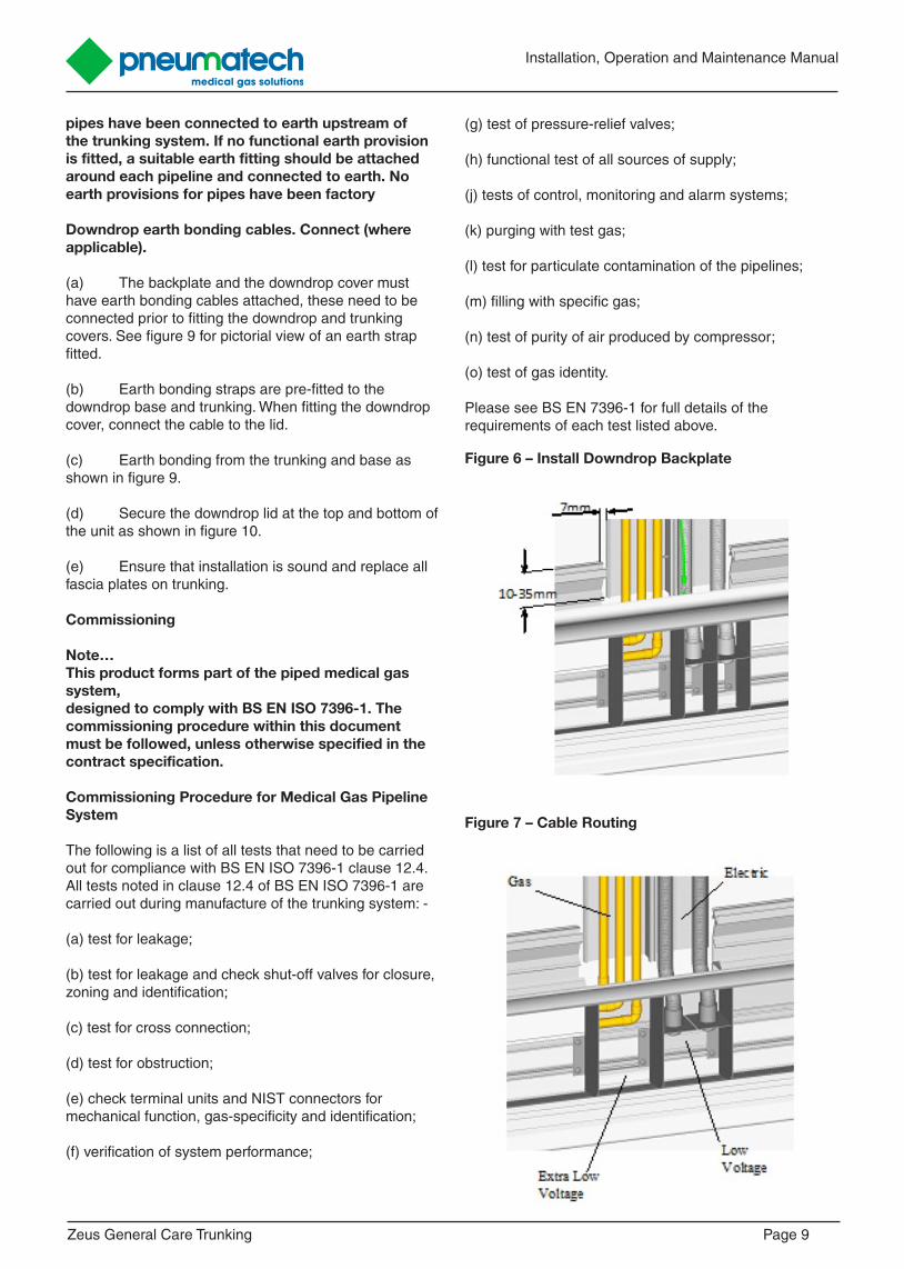
(b) Centralise the downdrop back plate between the entry point in the trunking. There should be approximately 7mm gap on either side of the downdrop (See Figure 6).
(c) Ensuring that downdrop is vertical and the rear face is in line with rear of trunking. With the back plate up against the line of the ceiling the bottom of the downdrop should be between 10 and 35mm below the line of the trunking (See figure 6).
(d) Mark the wall in the positions of the downdrop mounting holes.
(e) Fix to wall with adequate fixings, pack out as necessary.
(f) Do not replace cover plate at this stage. Only replace when installation is complete.
Pipework. Braze (where applicable). Note... The gas pipework already installed in the trunking has been workshop leak tested, only new joints made should normally be tested. Remove any plastic components around area to be brazed.
WARNING!Cross connection of medical gas pipelines could prove fatal. Only work on one gas service at a time, and ensure that all labelling is correct and main-tained throughout the pipeline length. Cross connec-tion tests are detailed in BS EN ISO 7396-1, of which copies are available from Pneumatech MGS. If in doubt ask.
(a) All brazed joints made should be made using the approved jointing technique as detailed in the contract specification. HTM02-01 and HTM 2022 installations should use the fluxless brazing technique with Oxygen-free Nitrogen purge.
(b) Make and braze all necessary joints.
Low voltage electrical connections. Connect (where applicable).
(a) The trunking is supplied pre-wired with a customer-specified number of low voltage ring/radial mains, which are terminated into the electrical sockets. For a radial main, the electrical contractor should terminate the supplies into the first socket on each circuit, which will be the socket closest to the feed end. Where a ring main is specified, the electrical contractor should terminate the supplies into the first and last
sockets on each circuit. These will be the sockets closest to and furthest from the feed end on each circuit. Segregation of the low voltage supplies is maintained through the downdrop (where applicable). 2 conduits are available to carry the low voltage cables through the downdrop to the trunking.
(b) Where integral lighting units are supplied, a terminal block is provided in the main body of the trunking system. A round bodied 2 core and earth cable (4-7mm diameter) should be brought into the trunking system, and terminated through the strain relief bushing provided. The supply to the lights should be fused so as to protect the 0.75 sq.mm cables factory fitted to the termination block.
(c) Where a single piece of trunking is installed all the internal pre-wiring has been carried out, however when 2 or more pieces are to be joined some final termination of low voltage cables is to be carried out as follows: -
At each trunking carcass split line marked cables will be coiled for connection to their respective components i.e. Ring 1 power sockets, Uplights, Reading Lights etc. These cables are to be connected by the electrical contractor.
Extra low voltage electrical connections. Connect (where applicable).
(a) Normally no extra-low voltage cables will be installed, this is the responsibility of the electrical contractor.
(b) Extra-low voltage cables are to be run within the lower channel in the main body behind the fascia plates.
(c) Segregation of extra-low voltage supplies is maintained through the downdrop (if used).
Trunking earth bonding cables. Connect.
(a) Top covers, bottom covers and fascia plates all have earth bonding cables attached, these should be connected prior to fitting the covers. See figure 8 for pictorial view of an earth strap fitted to cover.
(b) When joining two or more trunking carcass lengths an earth bonding strap must be fitted between the two adjoining backplates. This bonding strap is normally already fitted to one of the carcasses.
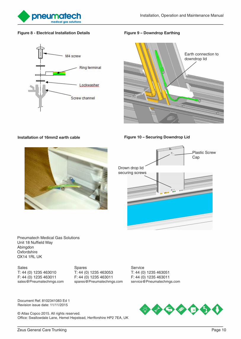
(c) At the feed end of the trunking, a 16mm2 earth conductor shall be brought in and attached as shown in figure 8. A ring crimp terminal should be fitted as shown using the lockwashers and screw supplied.
WARNING!A continuity test or visual check should be made on each pipeline to ensure that the medical gas
Installation, Operation and Maintenance Manual
Zeus General Care Trunking Page 9
pipes have been connected to earth upstream of the trunking system. If no functional earth provision is fitted, a suitable earth fitting should be attached around each pipeline and connected to earth. No earth provisions for pipes have been factory
Downdrop earth bonding cables. Connect (where applicable).
(a) The backplate and the downdrop cover must have earth bonding cables attached, these need to be connected prior to fitting the downdrop and trunking covers. See figure 9 for pictorial view of an earth strap fitted.
(b) Earth bonding straps are pre-fitted to the downdrop base and trunking. When fitting the downdrop cover, connect the cable to the lid.
(c) Earth bonding from the trunking and base as shown in figure 9.
(d) Secure the downdrop lid at the top and bottom of the unit as shown in figure 10.
(e) Ensure that installation is sound and replace all fascia plates on trunking.
Commissioning
Note…This product forms part of the piped medical gas system, designed to comply with BS EN ISO 7396-1. The commissioning procedure within this document must be followed, unless otherwise specified in the contract specification.
Commissioning Procedure for Medical Gas Pipeline System
The following is a list of all tests that need to be carried out for compliance with BS EN ISO 7396-1 clause 12.4. All tests noted in clause 12.4 of BS EN ISO 7396-1 are carried out during manufacture of the trunking system: -
(a) test for leakage;
(b) test for leakage and check shut-off valves for closure, zoning and identification;
(c) test for cross connection;
(d) test for obstruction;
(e) check terminal units and NIST connectors for mechanical function, gas-specificity and identification;
(f) verification of system performance;
(g) test of pressure-relief valves;
(h) functional test of all sources of supply;
(j) tests of control, monitoring and alarm systems;
(k) purging with test gas;
(l) test for particulate contamination of the pipelines;
(m) filling with specific gas;
(n) test of purity of air produced by compressor;
(o) test of gas identity.
Please see BS EN 7396-1 for full details of the requirements of each test listed above.
Figure 6 – Install Downdrop Backplate
Figure 7 – Cable Routing
Zeus General Care Trunking Page 10
Installation, Operation and Maintenance Manual
Figure 8 - Electrical Installation Details Figure 9 – Downdrop Earthing
Earth connection to downdrop lid
Drown drop lid securing screws
Plastic Screw Cap
Figure 10 – Securing Downdrop LidInstallation of 16mm2 earth cable
Document Ref. 8102341083 Ed 1 Revision issue date: 11/11/2015
© Atlas Copco 2015. All rights reserved.Office: Swallowdale Lane, Hemel Hepstead, Hertforshire HP2 7EA, UK
Sales Spares ServiceT: 44 (0) 1235 463010 T: 44 (0) 1235 463053 T: 44 (0) 1235 463051F: 44 (0) 1235 463011 F: 44 (0) 1235 463011 F: 44 (0) 1235 [email protected] [email protected] [email protected]
Pneumatech Medical Gas Solutions Unit 18 Nuffield WayAbingdonOxfordshireOX14 1RL UK