Zephyr Manual
60
Digitrax Command Control Starter Set Manual Includes: DCS50 Command Station Booster, PS315 Power Supply, LT1 LocoNet Cable & Decoder Tester Digitrax, Inc. 2443 Transmitter Road Panama City, Florida 32401 (850) 872 9890 - Fax (850) 872 9557 www.digitrax.com L o c o N e t R Digitrax Manuals & Instructions are updated periodically. Please visit www.digitrax.com for the latest version of all manuals. This manual was updated 08/10. C T C omplete rain ontrol
-
Upload
justin-gilmore -
Category
Documents
-
view
315 -
download
3
description
Manual For the digitrax Zephyr
Transcript of Zephyr Manual
Digitrax Command Control Starter Set Manual
Includes:DCS50 Command Station Booster,
PS315 Power Supply,LT1 LocoNet Cable & Decoder Tester
Digitrax, Inc.2443 Transmitter Road
Panama City, Florida 32401(850) 872 9890 - Fax (850) 872 9557
www.digitrax.com
LLooccooNNeett
R
Digitrax Manuals & Instructions are updated periodically. Please visit www.digitrax.com for the latest version of all manuals.
This manual was updated 08/10.
CTC
ompleterainontrol
©2004-2010 Digitrax, Inc. www.digitrax.com 1
Digitrax�Zephyr�Set�Manual
table�of�Contents
1.0 Introduction ......................................................................................3
2.0 Zephyr Components ..........................................................................3
3.0 Preparing Your Locomotives ............................................................3
4.0 Preparing Your Layout ....................................................................3
Quick Start
5.0 DCS50 Front Panel Controls And Indicators ................................4
6.0 DCS50 LED Display ........................................................................5
7.0 Hooking Up Your Zephyr ................................................................6
8.0 Run A Locomotive Without a DCC Decoder ..................................8
9.0 Run A DCC Equipped Locomotive ..............................................10
10.0 Locomotive Direction Control ........................................................12
11.0 Shutting Down the System ............................................................12
12.0 Resuming Operation ......................................................................12
13.0 Quick Start Troubleshooting ..........................................................13
Advanced Features
14.0 Locomotive Speed Control ............................................................14
14.1 Speed Limit ......................................................................................14
15.0 Stop and Emergency Stop ............................................................14
15.1 Setting A Loco to Zero Speed ..........................................................14
15.2 Brake Operation ................................................................................14
15.3 Emergency Stop ................................................................................15
16.0 Programming Your Decoder ..........................................................16
16.1 Setting Up A Service Mode Programming Track ............................16
16.2 Changing the Decoder Address ........................................................18
16.3 Programming Configuration Variables Other Than Addresses ........19
16.4 Programming On The Mainline: Operations Mode Programming ..21
16.5 Error Messages When Programming ................................................22
16.6 Reading Back CV Values Programmed ............................................22
16.7 Configuration Variable Programming Notes......................................23
17.0 Functions ..........................................................................................24
17.1 Controlling Functions F0-F8 ..........................................................24
17.1.1 Function 0 (F0) ..............................................................................24
17.1.2 Functions 1, 4, 5, 6, 7, & 8 ..............................................................24
17.1.3 Function 2 (F2) ................................................................................24
17.1.4 Function 3 (F3) ................................................................................25
17.2 Function Operation Troubleshooting ................................................25
18.0 MU (Multiple Unit) Operations ....................................................26
18.1 Adding a Locomotive To An MU ....................................................26
18.2 Removing A Loco From An MU ......................................................28
18.3 MU of Mismatched Locomotives ....................................................28
18.4 Controlling Functions On MU’ed Locomotives ..............................28
19.0 Stealing: When An Address Is Running on Another Throttle ....29
20.0 Releasing An Address From A Throttle ........................................30
20.1 Dispatching Addresses or MUs ........................................................30
21.0 The FuLL Message ..........................................................................31
22.0 DCS50 Error Messages ..................................................................32
23.0 Decoder Speed Step Settings ........................................................32
23.1 Changing Speed Step Settings: Status Editing ................................33
24.0 SWITCH Mode ..............................................................................34
25.0 Adding Throttles: LocoNet & Jump Ports ..................................35
25.1 Adding LocoNet Throttles To Your DCS50 ....................................35
25.2 Jump Ports: Using A DC Power Pack As An Additional Throttle ....35
25.3 Adding Another DCS50 ....................................................................39
25.3.1 Assigning Throttle Identities..............................................................40
25.3.2 Making LocoNet Cables ..................................................................42
25.3.3 Testing LocoNet Cables with an LT1 ................................................42
26.0 Locomotive Dispatching Procedures ............................................43
27.0 Troubleshooting ..............................................................................44
27.1 Nothing is responding ......................................................................44
27.2 No Power or Intermittent Operation ................................................44
27.2.1 The Quarter Trick ..............................................................................44
27.2.2 The LT1 Tester ..................................................................................44
27.3 Emergency Stop ................................................................................44
27.4 Mechanical Drive Train Problems ....................................................44
27.5 “Strange” Locomotive Lights ..........................................................44
27.6 Decoder Won’t Respond ..................................................................45
27.7 I’m totally lost! ................................................................................46
27.8 DCS50 Shutdown ..............................................................................46
28.0 DCS50 Option Switch Setup ..........................................................46
29.0 LocoNet: The Digitrax Difference! ..............................................48
29.1 System Architecture ........................................................................48
29.1 System Architecture ........................................................................48
30.0 FCC Information ............................................................................50
31.0 Warranty and Repair Information ..............................................51
32.0 Specifications ....................................................................................52
Index ..................................................................................................53Digitrax, the Digitrax Train Logos, LocoNet, Super Empire Builder Xtra, Super Chief Xtra, Transponding,
SuperSonic, AutoReversing, Zephyr, Jump & others are trademarks of Digitrax, Inc. This manual may not be
reproduced in any form without permission.
©2004-2010 Digitrax, Inc. www.digitrax.com 3
1.0 IntroductionCongratulations on your purchase of a Digitrax Zephyr Starter Set!Your success with and enjoyment of our products are very important to us.After all, this is a hobby and it is FUN!!! Please read this manual carefullybefore you install your system. We have included lots of hints and operatingideas based on our experience with the Digitrax system. The Zephyr isdesigned for easy operation and expandability with Digitrax LocoNet. WithLocoNet, just plug in system components to build the layout control systemthat you’ve always wanted! If you have questions not covered by this manualplease contact your dealer or Digitrax technical support.
2.0 Zephyr ComponentsYour Zephyr Starter Set contains:
DCS50 All-in-one command station, throttle and booster to run your trains.
PS315 Power supply to provide power to run your DCS50.
LT1 Decoder and LocoNet Cable Tester
Zephyr Manual
Digitrax Decoder Manual
3.0 Preparing Your LocomotivesYou will be able to run one locomotive without a decoder on your Zephyrsystem along with the ones with decoders. So, even if you don’t have a locowith a decoder, you can still hook up your new system and try it out rightaway!You will need to install decoders in the locomotives you want to run in orderto take full advantage of your new Digital Command Control system. Thedecoder allows you to individually control each locomotive’s speed, direc-tion, lights and other functions. We don’t include decoders with our startersets because there are so many different decoders available for so many dif-ferent locomotives. We want to be sure you don’t spend money on adecoder that may not be the best choice for your particular locomotives.Your dealer can help you select the best decoder choices for your layoutfrom Digitrax wide variety of decoders. Our web site www.digitrax.com con-tains information about decoder installations and which decoders are bestfor particular locomotives.A Digitrax Decoder Manual is included with all Starter Sets so you will haveit available to use with any Digitrax decoders you choose to go with the set.
4.0 Preparing Your LayoutDigitrax simplifies layout wiring for new layouts. If you already have a layout,
you probably won’t need to rewire to install your Digitrax Zephyr. Since the
DCC signal travels with the power on the rails, you must have power to the
track in all locations so that the decoders can receive the signal and respond to
your commands.For more information about layout wiring visit our web site.
©2004-2010 Digitrax, Inc. www.digitrax.com 4
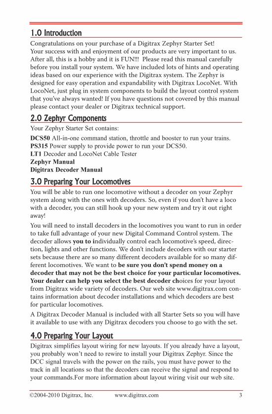
5.0 DCS50 Front Panel Controls And Indicators
Before you select and run a locomotive, take a few minutes to look at the
DCS50’s controls and display.
1. The Throttle Knob is the large silver and black knob on the right side ofthe DCS50. The Throttle Knob controls locomotive speed from StOp toFull speed. Turn it clockwise to increase speed and counter clockwise todecrease speed.
2. The Direction Control Lever is the small silver lever (located on the leftside of the DCS50) that controls the locomotive’s direction of travel,FOrwarD or reverSe. This knob also controls the BraKe. When youhave a loco address selected and the Direction Control Lever lever is inthe BraKe position, the Brake Indicator Dot will blink until the loco stopsand then remain on steady to let you know that the BraKe is on. When youmove the lever to FOrwarD or reverSe, the Brake Indicator Dot willflash to let you know that the brake is released and the loco is acceleratingto the speed shown on the Throttle Knob.
3. There are 20 KeyS on the DCS50’s keypad, including a full numeric key-pad for direct entry of numerical values. Some keys have more than one usewhen used in combination with other keys or sequences of keystrokes.
4. The Track Status Indicator Dot is lit when track power is on and unlitwhen track power is off. Track power must be on to operate the trains onthe track. Simply press the pOwer key to toggle between power on andoff. If you need to stop the whole layout, press the pOwer key to turn offtrack power and put everything on the layout into “Emergency Stop.”
RR
B R A K EB R A K E S T O PS T O P F U L LF U L L
11
22
33
44
55
S W I T C HS W I T C HM UM UJ U M PJ U M PF U N C T I O NF U N C T I O N
1 2
4 5
7 8
S W I T C H
+ -
E X I T
P O W E R
PROG
MODE
t c
3
6
9
S T E P S
L O C O
J U M P
M U
T R A C K T R A C KS T A T U SS T A T U S
0
CV CV-RD CV-WR
D C S 5 0D C S 5 0
F O R W A R DF O R W A R D
R E V E R S ER E V E R S E
12
4 3
©2004-2010 Digitrax, Inc. www.digitrax.com 5
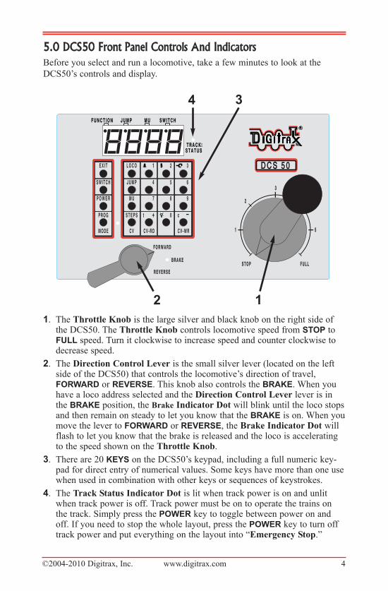
6.0 DCS50 LED DisplayThe DCS50’s LED Display is made up of 4 digits/letters on the main part of
the screen and 4 Indicator Dots across the top of the screen.
When you are running a locomotive, you will see the address of that locomo-
tive in the display and the Function Indicator Dot will be lit. This means that
the throttle knob will control speed, the direction lever will control direction
and braking and the number keys will control the functions on the locomotive.
You will see the following display if you are running loco address 1873 on
your local throttle.
The LCD has three additional Indicator Dots associated with more advanced
features available on the DCS50:
The Jump Indicator Dot lets you know if one or more Jump™ ports are
active. See Section 25.2.
The MU Indicator Dot lets you know if Multiple Unit (MU) or consisting is
active. See Section 18.
The Switch Indicator Dot lets you know when you are in switch mode for
controlling turnouts or setting up system options. See Section 24 for turnout
operation and Section 28 for Option Switch set up information.
S W I T C HS W I T C HM UM UJ U M PJ U M PF U N C T I O NF U N C T I O NFunction Indicator Dot On Locomotive
Address
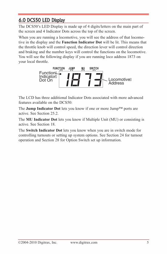
7.0 Hooking Up Your Zephyr7.1�Zephyr�rear�panel�Connections
1. rail�a & B for connecting the DCS50 to the rails on the layout.
2. prOg�a & B for hooking up the programming track. Section 16.1.
3. JuMp 1 & 2 for connecting one or two smooth DC power packs to the sys-tem for use as additional throttles. Section 25.2
4. pOwer�in-plug in the PS315 here.
5. lOCOnet�pOrtS�a & B for connecting the DCS50 to other LocoNetdevices for expanding your layout.
6. yOur�layOut. You can connect Zephyr to most existing layouts.
BAJUM
P 1
JUM
P1
GROU
NDGR
OUND
RAIL
BRA
ILB
JUM
P 2
JUM
P2
PROG
APR
OGA
RAIL
ARA
ILA
PROG
BPR
OGB L O C O N E TL O C O N E T
RP O W E R I NP O W E R I N
1 5 V A C1 5 V A C2 . 5 A M P S2 . 5 A M P S
PS315Power SupplyPlugged IntoWall Outlet
Layout Power District(Double Gapped)
Rail A
Rail B
D O N O T U S E W I T H T R A C KD O N O T U S E W I T H T R A C KO V E R 1 6 V O L T SO V E R 1 6 V O L T S
©2004-2010 Digitrax, Inc. www.digitrax.com 6
3 1 52
4
6
©2004-2010 Digitrax, Inc. www.digitrax.com 7
7.2�Connecting�the�Zephyr�is�as�easy�as�1-2-3These simple instructions will help you get up and running quickly. A full
description of all controls and technical reference information are included later
in this manual. This section assumes that you are using a new set straight out of
the box.
1. Hook up the wires from the track to the rail�a & rail�B�terminals onthe DCS50. Insert the wire from one rail of the track into the rail�a termi-nal on the back of the DCS50. Insert the wire from the other rail of thetrack into the rail�B terminal. Turn the screw counter clockwise to openthe connector and clockwise to close it once the wire is in place.
2. Plug the barrel connector from the PS315 into the pOwer in jack on theback of the DCS50. Plug the body of the PS315 in to a regular wall outlet.
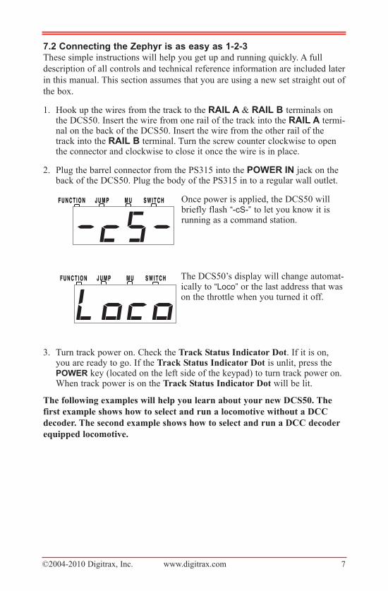
Once power is applied, the DCS50 willbriefly flash “-cS-” to let you know it isrunning as a command station.
The DCS50’s display will change automat-ically to “Loco” or the last address that wason the throttle when you turned it off.
3. Turn track power on. Check the Track Status Indicator Dot. If it is on,you are ready to go. If the Track Status Indicator Dot is unlit, press thepOwer key (located on the left side of the keypad) to turn track power on.When track power is on the Track Status Indicator Dot will be lit.
The following examples will help you learn about your new DCS50. The
first example shows how to select and run a locomotive without a DCC
decoder. The second example shows how to select and run a DCC decoder
equipped locomotive.
S W I T C HS W I T C HM UM UJ U M PJ U M PF U N C T I O NF U N C T I O N
S W I T C HS W I T C HM UM UJ U M PJ U M PF U N C T I O NF U N C T I O N
©2004-2010 Digitrax, Inc. www.digitrax.com 8
8.0 Run A Locomotive Without a DCC DecoderGetting started with your Zephyr system is easy. In the proceeding steps you
have familiarized yourself with the controls and connected the Zephyr to your
layout. Just follow these simple steps and you’ll be running one of your exist-
ing DC trains in just a few more minutes.
1. Set the DCS50’s Throttle Knob to StOp.
2. Place an analog locomotive, one without a decoder installed, on your layoutthat is controlled by your DCS50.
3. Check the DCS50’s Track Status Indicator Dot to be sure that track poweris turned on. Press pOwer to turn track power on if necessary.
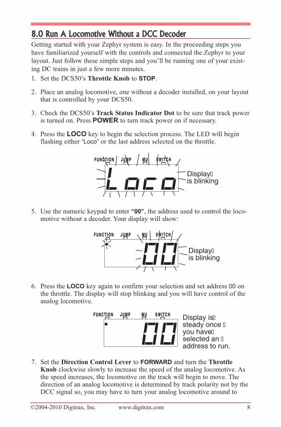
4. Press the lOCO key to begin the selection process. The LED will beginflashing either “Loco” or the last address selected on the throttle.
5. Use the numeric keypad to enter “00”, the address used to control the loco-motive without a decoder. Your display will show:
6. Press the lOCO key again to confirm your selection and set address 00 onthe throttle. The display will stop blinking and you will have control of theanalog locomotive.
7. Set the Direction Control Lever to FOrwarD and turn the ThrottleKnob clockwise slowly to increase the speed of the analog locomotive. Asthe speed increases, the locomotive on the track will begin to move. Thedirection of an analog locomotive is determined by track polarity not by theDCC signal so, you may have to turn your analog locomotive around to
S W I T C HS W I T C HM UM UJ U M PJ U M PF U N C T I O NF U N C T I O N Display is steady once you have selected an address to run.
S W I T C HS W I T C HM UM UJ U M PJ U M PF U N C T I O NF U N C T I O N
Display is blinking
S W I T C HS W I T C HM UM UJ U M PJ U M PF U N C T I O NF U N C T I O N
Display is blinking
©2004-2010 Digitrax, Inc. www.digitrax.com 9
match the direction of travel on the Direction Control Lever. The DCS50’sTrack Status Indicator Dot should slightly change color as you change thespeed setting.
8. Change the Direction Control Lever to reverSe and the loco will movein the opposite direction.
9. Change the Direction Control Lever to the BraKe position and the locowill slow down and stop. Move the Direction Control Lever to FOrwarDor reverSe and the loco will move again.
10.Turn the Throttle Knob to StOp and the loco will stop moving.
11. If you have a headlight installed in your loco, it will be on and stay onbecause with DCC there is constant power to the track.
A locomotive without a DCC decoder is called an analog locomotive. While
an analog locomotive, without a decoder, is sitting still on your digital layout,
you will hear a “singing” sound. This is caused by the DCC track signal when
it is applied to an analog locomotive. Once the analog locomotive is moving,
this sound will change and be less noticeable. To avoid heat build up in your
locos without decoders, Digitrax recommends that analog locos NOT be left
sitting on DCC powered track for long periods of time when they are not run-
ning.
Address 00 is reserved for running an analog locomotive. Your analog locomo-
tives will not run with any other address. As with a regular DC system, only
one analog locomotive can be controlled at a time. If you try to run more than
one analog locomotive at the same time on the layout all of the analog locos
will respond to the commands sent to address 00. By adding DCC decoders to
your locomotives and additional throttles to your system, you can individually
control up to 10 locomotives at the same time with your Zephyr Set.
©2004-2010 Digitrax, Inc. www.digitrax.com 10
9.0 Run A DCC Equipped Locomotive 9.1�Before�you�run�your�first�DCC�equipped�locomotive,�there�are�a
few�things�you�need�to�know:1. Each DCC decoder can be assigned a unique address that is used by the
system to send commands to that decoder. The address is a numeric valueremembered by the decoder in the loco until you change it.
2. You program each of your locomotives with its own unique address so thatyou can run them independently.
3. To select a DCC locomotive and run it, you must know its address.
4. Digitrax decoders are set up at the factory with address 03. This means thatwhen you take a Digitrax decoder out of the package and install it in yourloco, you can select address 03 on your throttle and run the decoder. Youcan easily change this address by following the instructions in Section 16.2.To make the examples easier to follow, lets leave everything at the factorysettings.
5. If you do not know the address of the DCC locomotive you want to run,you can either read back the decoder’s address or program it to the addressyou want to use. These procedures are covered in Section 16.6.
9.2�Selecting�and�running�your�DCC�locomotiveTo select and run a DCC equipped locomotive with a known address follow
these steps:1. Set the DCS50’s Throttle Knob to StOp.
2. Place a DCC equipped locomotive (one with a decoder installed) on yourdigital layout that is controlled by your DCS50. In this example we assumethat you have a new Digitrax decoder that is factory programmed to address03. If your decoder is using a different address, simply use that address asyou follow these instructions.
3. Check the DCS50’s Track Status Indicator Dot to be sure that track poweris turned on. Press the pOwer key to turn track power on if necessary.
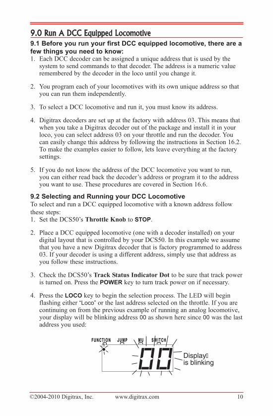
4. Press the lOCO key to begin the selection process. The LED will beginflashing either “Loco” or the last address selected on the throttle. If you arecontinuing on from the previous example of running an analog locomotive,your display will be blinking address 00 as shown here since 00 was the lastaddress you used:
S W I T C HS W I T C HM UM UJ U M PJ U M PF U N C T I O NF U N C T I O N
Display is blinking
©2004-2010 Digitrax, Inc. www.digitrax.com 11
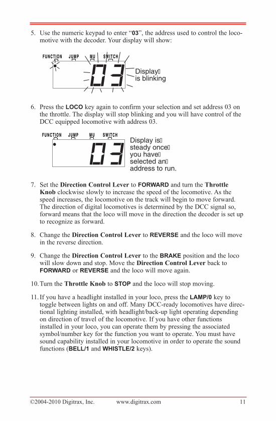
5. Use the numeric keypad to enter “03”, the address used to control the loco-motive with the decoder. Your display will show:
6. Press the lOCO key again to confirm your selection and set address 03 onthe throttle. The display will stop blinking and you will have control of theDCC equipped locomotive with address 03.
7. Set the Direction Control Lever to FOrwarD and turn the ThrottleKnob clockwise slowly to increase the speed of the locomotive. As thespeed increases, the locomotive on the track will begin to move forward.The direction of digital locomotives is determined by the DCC signal so,forward means that the loco will move in the direction the decoder is set upto recognize as forward.
8. Change the Direction Control Lever to reverSe and the loco will movein the reverse direction.
9. Change the Direction Control Lever to the BraKe position and the locowill slow down and stop. Move the Direction Control Lever back toFOrwarD or reverSe and the loco will move again.
10.Turn the Throttle Knob to StOp and the loco will stop moving.
11. If you have a headlight installed in your loco, press the laMp/0 key to toggle between lights on and off. Many DCC-ready locomotives have direc-tional lighting installed, with headlight/back-up light operating dependingon direction of travel of the locomotive. If you have other functionsinstalled in your loco, you can operate them by pressing the associated symbol/number key for the function you want to operate. You must havesound capability installed in your locomotive in order to operate the soundfunctions (Bell/1 and whiStle/2 keys).
S W I T C HS W I T C HM UM UJ U M PJ U M PF U N C T I O NF U N C T I O NDisplay is steady once you have selected an address to run.
S W I T C HS W I T C HM UM UJ U M PJ U M PF U N C T I O NF U N C T I O N
Display is blinking
©2004-2010 Digitrax, Inc. www.digitrax.com 12
10.0 Locomotive Direction Control Move the Direction Control Lever to FOrwarD or reverSe to change the
direction of the loco address running on the throttle. To determine the direction
of a loco that is not moving, simply look at the position of the lever. You can
move the lever quickly past the BraKe position with no adverse effects.
If you change direction while a loco is moving it will slow down to 0 speed
and then speed up to the commanded speed according to the decoder’s pro-
grammed CV values for deceleration and acceleration.
11.0 Shutting Down the SystemWhen you are finished with your session, you should shut down the DCS50 by
turning off power to the system.
1. Bring all locomotives on the layout to a stop by setting set the ThrottleKnob for each loco to StOp.
2. Turn track power off: Press the pOwer key, the DCS50’s Track StatusIndicator Dot will go off. The display will briefly display “Po” followed bytwo characters, the Po means power off, the two characters indicate whichsoftware version is installed in the unit. The display will automaticallyrevert to showing the last loco address selected on the throttle but sincetrack power is now off, it will not run the layout until you turn on trackpower again.
3. Unplug the PS315 power supply from the wall outlet.
When power is restored to the DCS50, it will “wake up” with all of the settings
as they were left when powered down. The power to the command station can
be left on all the time if desired.
12.0 Resuming OperationWhen you are ready to run trains again:
1. Set the DCS50’s Throttle Knob to StOp.
2. Plug in the PS315 power supply to the wall outlet and to the DCS50.
3. Press the pOwer key to turn on track power. The Track Status IndicatorDot will light up.
4. The DCS50 display will show the last locomotive address you were runningand be ready to begin right where you left off.
©2004-2010 Digitrax, Inc. www.digitrax.com 13
13.0 Quick Start TroubleshootingIf you encountered problems at any step in this Quick Start Section:
1. Try backing up a step until you get results described. The steps included inthis installation procedure are set up so that if you follow them carefully,any problems you encounter will be easy to isolate and correct.
2. If you still have problems or if you have other questions, we encourage youto call, fax or e-mail your favorite Digitrax dealer. If your dealer is not ableto help, please contact Digitrax directly.
There are thousands of successful Digitrax installations around the world and
we want to be sure that yours is one of them.
QUICK INSTALLATION Notes for users of Digitrax decoders that have
already been programmed and decoders not made by Digitrax:
1. The DCS50 command station operates in 128 speed step mode. If you areusing a locomotive with a decoder that does not have 128 step capabilityyou will have to adjust either the decoder or the DCS50 so that both areusing the same number of speed steps to communicate. We call this proce-dure status editing. You can status edit each individual decoder (seeSection 23) or you can change the DCS50’s system default by setting theDCS50’s Option Switches 21-23 and run all of your decoders with fewerspeed steps to accommodate these decoders (see Section 28).
2. If you can’t control the operation of the lights in your decoder equippedlocomotive with the DCS50, be sure that the decoder itself is programmedto run in 128 speed steps.
What’s Next?
Now that you have successfully set up and run your Zephyr Set, it’s time to
learn more about the features and options it has to offer.
Please read the manual and take time to understand and master each topic. Your
Zephyr Set is the gateway to all the possibilities and options offered by
Digitrax and LocoNet so the best advice is to take it step by step and don’t try
to do everything at once.
The Digitrax Big Book of DCC is an excellent resource available to you as you
expand your layout. The Big Book is full of examples that show you how you
can have even more fun with your layout.
©2004-2010 Digitrax, Inc. www.digitrax.com 14
14.0 Locomotive Speed ControlTo control the speed of a locomotive:1. Select the loco address on the throttle.
2. Turn the Throttle Knob clockwise to increase speed and counterclockwiseto decrease speed.
14.1��Speed�limitYou can limit the speed on any locomotive controlled by the DCS50. This fea-
ture is very useful if you are running your layout with young children who
want to make the trains GO FAST!!! By setting a reasonable speed limit on the
throttles used by the children, everyone can have more fun with the trains.
To set a “speed limit” for your DCS50’s local throttle follow these simple
steps:1. Press the prOg key. The display shows the last programming mode used.
2. Press the Mu key. The display shows “id00”.
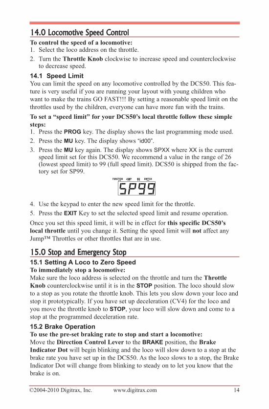
3. Press the Mu key again. The display shows SPXX where XX is the currentspeed limit set for this DCS50. We recommend a value in the range of 26(lowest speed limit) to 99 (full speed limit). DCS50 is shipped from the fac-tory set for SP99.
4. Use the keypad to enter the new speed limit for the throttle.
5. Press the exit Key to set the selected speed limit and resume operation.
Once you set this speed limit, it will be in effect for this specific DCS50’s
local throttle until you change it. Setting the speed limit will not affect any
Jump™ Throttles or other throttles that are in use.
15.0 Stop and Emergency Stop15.1�Setting�a�loco�to�Zero�SpeedTo immediately stop a locomotive:
Make sure the loco address is selected on the throttle and turn the Throttle
Knob counterclockwise until it is in the StOp position. The loco should slow
to a stop as you rotate the throttle knob. This lets you slow down your loco and
stop it prototypically. If you have set up deceleration (CV4) for the loco and
you move the throttle knob to StOp, your loco will slow down and come to a
stop at the programmed deceleration rate.
15.2�Brake�OperationTo use the pre-set braking rate to stop and start a locomotive:
Move the Direction Control Lever to the BraKe position, the Brake
Indicator Dot will begin blinking and the loco will slow down to a stop at the
brake rate you have set up in the DCS50. As the loco slows to a stop, the Brake
Indicator Dot will change from blinking to steady on to let you know that the
brake is on.
S W I T C HS W I T C HM UM UJ U M PJ U M PF U N C T I O NF U N C T I O N
©2004-2010 Digitrax, Inc. www.digitrax.com 15
Move the Direction Control Lever to the FOrwarD or reverSe position
and the loco will accelerate at the programmed brake rate to the speed on the
throttle knob. As the loco accelerates, the Brake Indicator Dot will flash dur-
ing acceleration and go off when the loco has reached the speed set on the
Throttle Knob.
The DCS50 is shipped with the brake rate set at 02. This gives a small amount
of deceleration when the brake is applied and a small amount of acceleration
when the brake is released.
To change the brake rate:1. Press the prOg key. The display shows the last programming mode used.
2. Press the Mu key. The display shows id00.
3. Press the Mu key again. The display shows SPXX where XX is the currentspeed limit set for this DCS50.
4. Press the Mu key again. The display shows brXX where XX is the currentbrake rate set for this DCS50.
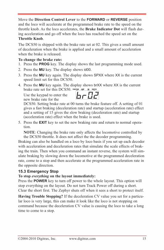
Use the keypad to enter thenew brake rate for theDCS50. Setting brake rate at 00 turns the brake feature off. A setting of 01gives a fast braking (deceleration rate) and startup (acceleration rate) effectand a setting of 15 gives the slow braking (deceleration rate) and startup(acceleration rate) effect when the brake is used.
5. Press the exit key to set the new braking rate and return to normal opera-tion.
NOTE: Changing the brake rate only affects the locomotive controlled bythe DCS50 throttle. It does not affect the the decoder programming.
Braking can also be handled on a loco by loco basis if you set up each decoder
with acceleration and deceleration rates that simulate the scale effects of brak-
ing the train. Then when you command an instant reverse, the system will sim-
ulate braking by slowing down the locomotive at the programmed deceleration
rate, come to a stop and then accelerate at the programmed acceleration rate in
the opposite direction.
15.3�emergency�StopTo stop everything on the layout immediately:
Press the pOwer key to turn off power to the whole layout. This option will
stop everything on the layout. Do not turn Track Power off during a short.
Clear the short first. The Zephyr shuts off when it sees a short to protect itself.
Having Trouble Stopping? If the deceleration CV value you set for a particu-
lar loco is very large, this can make it look like the loco is not stopping on
command because the deceleration CV value is causing the loco to take a long
time to come to a stop.
S W I T C HS W I T C HM UM UJ U M PJ U M PF U N C T I O NF U N C T I O N
©2004-2010 Digitrax, Inc. www.digitrax.com 16
16.0 Programming Your DecoderYour DCC Decoders have many different configuration variables (CVs for
short) that let you set up a different set of characteristics for each decoder
installed in a locomotive. When you want to change a loco’s address, set up
how its lights work, change its momentum characteristics, etc. you will pro-
gram new CV values into the appropriate CVs to set it up just the way you
want.
Each CV controls a characteristic of the decoder. See your decoder manual for
a list of the most commonly used CVs and their meanings. A Digitrax Decoder
Manual is included as a part of your Zephyr system. Each decoder comes pre-
programmed with factory settings that will let you run it right away. We recom-
mend that you use the factory settings until you are comfortable with running
your layout with Digital Command Control.
The factory set address for all Digitrax decoders is 03. This is the first CV you
will want to change because it is not very useful to have all of your locos
respond to the same address.
Decoders are programmed when the command station sends programming
information to them through the rails. Your DCS50 supports two types of pro-
gramming:
Service Mode Programming is done on an electrically isolated programming
track. Using this mode, the command station broadcasts programming informa-
tion to all decoders on the program track. Because this is a broadcast mode, we
must isolate the decoder we want to program from the others on the layout by
using a separate programming track that is connected to the command station
for programming but not powered for operation of the locomotive. This mode
works with all DCC decoders. This is the most commonly used programming
method.
Operations Mode Programming is done on the layout by sending program-
ming commands to a specific locomotive address. To use this mode, you must
have decoders that are capable of operations mode programming.
16.1�Setting�up�a�Service�Mode�programming�trackYour DCS50 has two sets of DCC outputs. This means that you will be able to
program decoders using one set of DCC outputs while the layout is running on
the other set of DCC outputs. When you hooked up your DCS50 to the layout,
you used the rail�a�& rail�B connections to the track. Now we will use the
prOg a�& prOg�B outputs to set up a service mode programming track.
nOte: The programming track is powered for programming only and cannot
run locomotives. You will have to manually move your locomotive on to the
track whether using the siding or isolated track programming setup.
©2004-2010 Digitrax, Inc. www.digitrax.com 17
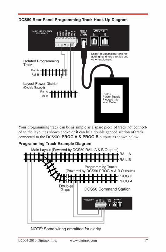
DCS50�rear�panel�programming�track�hook�up�Diagram
Your programming track can be as simple as a spare piece of track not connect-
ed to the layout as shown above or it can be a double gapped section of track
connected to the DCS50’s prOg�a�& prOg�B outputs as shown below.
programming�track�example�Diagram
BAJUMP
1JU
MP1
GROU
NDGR
OUND
RAIL
BRA
ILB
JUMP
2JU
MP2
PROG
APR
OGA
RAIL
ARA
ILA
PROG
BPR
OGB L O C O N E TL O C O N E T R
P O W E R I N P O W E R I N1 5 V A C 1 5 V A C
2 . 5 A M P S2 . 5 A M P S
DCS50 Command Station
NOTE: Some wiring ommitted for clarity
PROG BPROG A
RAIL ARAIL B
Programming Track (Powered by DCS50 PROG A & B Outputs)
Double Gaps
Main Layout (Powered by DCS50 RAIL A & B Outputs)
D O N O T U S E W I T H T R A C K D O N O T U S E W I T H T R A C KO V E R 1 6 V O L T SO V E R 1 6 V O L T S
BAJUM
P 1
JUM
P1
GROU
NDGR
OUND
RAIL
BRA
ILB
JUM
P 2
JUM
P2
PROG
APR
OGA
RAIL
ARA
ILA
PROG
BPR
OGB L O C O N E TL O C O N E T
RP O W E R I NP O W E R I N
1 5 V A C1 5 V A C2 . 5 A M P S2 . 5 A M P S
PS315Power SupplyPlugged IntoWall Outlet
Layout Power District(Double Gapped)
Rail A
Rail B
Isolated ProgrammingTrack
Rail A
Rail B
LocoNet Expansion Ports for adding handheld throttles and other equipment.
D O N O T U S E W I T H T R A C KD O N O T U S E W I T H T R A C KO V E R 1 6 V O L T SO V E R 1 6 V O L T S
©2004-2010 Digitrax, Inc. www.digitrax.com 18
16.2�Changing�the�Decoder�address1. Be sure that only the locomotive you want to program is on the program-
ming track.
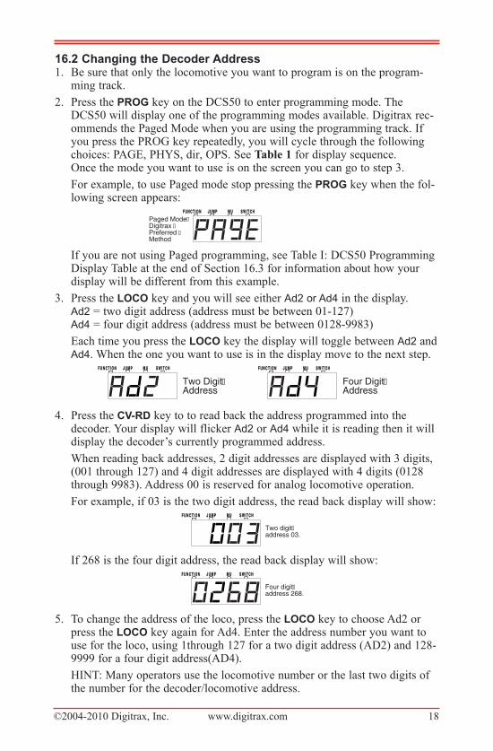
2. Press the prOg key on the DCS50 to enter programming mode. TheDCS50 will display one of the programming modes available. Digitrax rec-ommends the Paged Mode when you are using the programming track. Ifyou press the PROG key repeatedly, you will cycle through the followingchoices: PAGE, PHYS, dir, OPS. See Table 1 for display sequence. Once the mode you want to use is on the screen you can go to step 3.
For example, to use Paged mode stop pressing the prOg key when the fol-lowing screen appears:
If you are not using Paged programming, see Table I: DCS50 ProgrammingDisplay Table at the end of Section 16.3 for information about how yourdisplay will be different from this example.
3. Press the lOCO key and you will see either Ad2 or Ad4 in the display. Ad2 = two digit address (address must be between 01-127)Ad4 = four digit address (address must be between 0128-9983)
Each time you press the lOCO key the display will toggle between Ad2 andAd4. When the one you want to use is in the display move to the next step.
4. Press the Cv-rD key to to read back the address programmed into thedecoder. Your display will flicker Ad2 or Ad4 while it is reading then it willdisplay the decoder’s currently programmed address.
When reading back addresses, 2 digit addresses are displayed with 3 digits,(001 through 127) and 4 digit addresses are displayed with 4 digits (0128through 9983). Address 00 is reserved for analog locomotive operation.
For example, if 03 is the two digit address, the read back display will show:
If 268 is the four digit address, the read back display will show:
5. To change the address of the loco, press the lOCO key to choose Ad2 orpress the lOCO key again for Ad4. Enter the address number you want touse for the loco, using 1through 127 for a two digit address (AD2) and 128-9999 for a four digit address(AD4).
HINT: Many operators use the locomotive number or the last two digits ofthe number for the decoder/locomotive address.
S W I T C HS W I T C HM UM UJ U M PJ U M PF U N C T I O NF U N C T I O N
Four digit address 268.
S W I T C HS W I T C HM UM UJ U M PJ U M PF U N C T I O NF U N C T I O N
Two digit address 03.
S W I T C HS W I T C HM UM UJ U M PJ U M PF U N C T I O NF U N C T I O N
Two Digit Address
S W I T C HS W I T C HM UM UJ U M PJ U M PF U N C T I O NF U N C T I O N
Four Digit Address
S W I T C HS W I T C HM UM UJ U M PJ U M PF U N C T I O NF U N C T I O NPaged Mode Digitrax Preferred Method
©2004-2010 Digitrax, Inc. www.digitrax.com 19
6. Press the Cv-wr key to write the address to the decoder. The display willflicker while the address is programmed and then will show the new addressin the display.
For example, to change the address from the two digit address 03 to the twodigit address 96, press the lOCO Key until Ad2 appears in the display thenuse the key pad to enter 96 and press the Cv-wr key to write the address.
7. When you are finished programming the address, press the exit key. Youare now ready to resume normal operations or proceed to programmingother configuration variables.
16.3�programming�Configuration�variables Other�than�addressesThere are many different CVs that have been defined to control many operating
characteristics of your locomotives. Your decoder manual has a complete list-
ing of CVs that are available in specific decoders, what they do and suggested
values for each CV. Programming these CVs is simple:
1. Be sure that only the locomotive you want to program is on the program-ming track.
2. Press the prOg Key to enter programming mode. The DCS50 will displayone of the programming modes available. Digitrax recommends the PagedMode when you are using the programming track. As you press the prOgKey repeatedly, you will cycle through the following choices:
PAGE, PHYS, dir, OPS
Once the mode you want to use is on the screen you can go to step 3.
For example, to use Paged mode stop pressing the prOg Key when the fol-lowing screen appears:
3. Press the Cv Key and you will see P followed by the last CV number usedby the DCS50. The “P” indicates that you are in paged programming mode.
4. Enter the CV number you want to program. For example, if you want to setup acceleration which is controlled by CV03, use the keypad to enter 3.
5. Press the Cv-rD key to to read back the data value currently programmedinto the decoder for the CV selected. Your screen will show something likethis:
The numbers will flash for a few seconds as the DCS50 command station
S W I T C HS W I T C HM UM UJ U M PJ U M PF U N C T I O NF U N C T I O N
S W I T C HS W I T C HM UM UJ U M PJ U M PF U N C T I O NF U N C T I O N
S W I T C HS W I T C HM UM UJ U M PJ U M PF U N C T I O NF U N C T I O N
S W I T C HS W I T C HM UM UJ U M PJ U M PF U N C T I O NF U N C T I O NPaged Mode Digitrax Preferred Method
©2004-2010 Digitrax, Inc. www.digitrax.com 20
reads back the data value in the decoder. The “d” means that you are lookingat the CV’s data value that is programmed into the decoder, in this case theCV value is 0.
6. Use the numeric key pad to enter the new CV data value you want to pro-gram into the decoder. For example if you want to program the value of 2for CV03 which controls acceleration, enter 2.
Note: If you do not want to read back the CV’s data value as described instep 5, you can simply press the CV Key again to go directly to the dataentry mode. In this case, the display will show “d” followed by 3 digits.When you see this display, use the key Pad to enter the new data value youwant to program.
7. Press Cv-wr to write the new data value selected to the CV. The displaywill flicker while the command station programs the decoder and the dis-play will show the data value programmed.
8. To program another CV, press the Cv key and enter the CV number youwant to program next and repeat steps 3-7 again.
9. When you are finished programming, press the exit key to resume normaloperations.
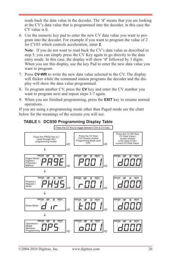
If you are using a programming mode other than Paged mode see the chart
below for the meanings of the screens you will see.
taBle�i:��DCS50�programming�Display table
a a
i
a a
i
a a
i
a a
i
a a
S W I T C HS W I T C HM UM UJ U M PJ U M PF U N C T I O NF U N C T I O NOperations Mode Mainline Programming
S W I T C HS W I T C HM UM UJ U M PJ U M PF U N C T I O NF U N C T I O N S W I T C HS W I T C HM UM UJ U M PJ U M PF U N C T I O NF U N C T I O N
S W I T C HS W I T C HM UM UJ U M PJ U M PF U N C T I O NF U N C T I O N
Direct Mode
S W I T C HS W I T C HM UM UJ U M PJ U M PF U N C T I O NF U N C T I O N S W I T C HS W I T C HM UM UJ U M PJ U M PF U N C T I O NF U N C T I O N
S W I T C HS W I T C HM UM UJ U M PJ U M PF U N C T I O NF U N C T I O N
Physical Register Mode
S W I T C HS W I T C HM UM UJ U M PJ U M PF U N C T I O NF U N C T I O N S W I T C HS W I T C HM UM UJ U M PJ U M PF U N C T I O NF U N C T I O N
S W I T C HS W I T C HM UM UJ U M PJ U M PF U N C T I O NF U N C T I O NPaged Mode Digitrax Preferred Method
S W I T C HS W I T C HM UM UJ U M PJ U M PF U N C T I O NF U N C T I O N S W I T C HS W I T C HM UM UJ U M PJ U M PF U N C T I O NF U N C T I O N
Press the PROG Key to cycle through the
programming modes
Press the CV Key CV# Screen shows
Progamming Mode and CV#
Press the CV-RD Key CV Data Value screen shows
d (for data) & the current CV Data Value
Press the CV Key to toggle between CV# & CV Data
©2004-2010 Digitrax, Inc. www.digitrax.com 21
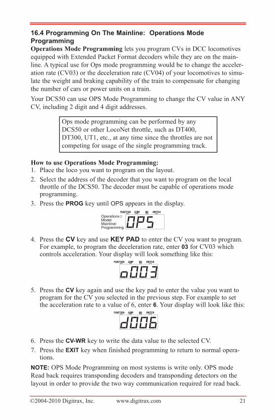
16.4�programming�On�the�Mainline:��Operations�Mode
programmingOperations Mode Programming lets you program CVs in DCC locomotives
equipped with Extended Packet Format decoders while they are on the main-
line. A typical use for Ops mode programming would be to change the acceler-
ation rate (CV03) or the deceleration rate (CV04) of your locomotives to simu-
late the weight and braking capability of the train to compensate for changing
the number of cars or power units on a train.
Your DCS50 can use OPS Mode Programming to change the CV value in ANY
CV, including 2 digit and 4 digit addresses.
How to use Operations Mode Programming:1. Place the loco you want to program on the layout.
2. Select the address of the decoder that you want to program on the localthrottle of the DCS50. The decoder must be capable of operations modeprogramming.
3. Press the prOg key until OPS appears in the display.
4. Press the Cv key and use Key�paD to enter the CV you want to program.For example, to program the deceleration rate, enter 03 for CV03 whichcontrols acceleration. Your display will look something like this:
5. Press the Cv key again and use the key pad to enter the value you want toprogram for the CV you selected in the previous step. For example to setthe acceleration rate to a value of 6, enter 6. Your display will look like this:
6. Press the Cv-wr key to write the data value to the selected CV.
7. Press the exit key when finished programming to return to normal opera-tions.
nOte: OPS Mode Programming on most systems is write only. OPS mode
Read back requires transponding decoders and transponding detectors on the
layout in order to provide the two way communication required for read back.
S W I T C HS W I T C HM UM UJ U M PJ U M PF U N C T I O NF U N C T I O N
S W I T C HS W I T C HM UM UJ U M PJ U M PF U N C T I O NF U N C T I O N
S W I T C HS W I T C HM UM UJ U M PJ U M PF U N C T I O NF U N C T I O NOperations Mode Mainline Programming
Ops mode programming can be performed by any
DCS50 or other LocoNet throttle, such as DT400,
DT300, UT1, etc., at any time since the throttles are not
competing for usage of the single programming track.
©2004-2010 Digitrax, Inc. www.digitrax.com 22
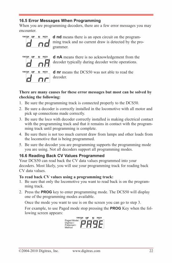
16.5�error�Messages�when�programmingWhen you are programming decoders, there are a few error messages you may
encounter.
d�nd means there is an open circuit on the program-
ming track and no current draw is detected by the pro-
grammer.
d�na means there is no acknowledgement from the
decoder typically during decoder write operations.
d�nr means the DCS50 was not able to read the
decoder.
There are many causes for these error messages but most can be solved by
checking the following:
1. Be sure the programming track is connected properly to the DCS50.
2. Be sure a decoder is correctly installed in the locomotive with all motor andpick up connections made correctly.
3. Be sure the loco with decoder correctly installed is making electrical contactwith the programming track and that it remains in contact with the program-ming track until programming is complete.
4. Be sure there is not too much current draw from lamps and other loads fromthe locomotive that is being programmed.
5. Be sure the decoder you are programming supports the programming modeyou are using. Not all decoders support all programming modes.
16.6�reading�Back�Cv�values programmedYour DCS50 can read back the CV data values programmed into your
decoders. Most likely, you will use your programming track for reading back
CV data values.
To read back CV values using a programming track:1. Be sure that only the locomotive you want to read back is on the program-
ming track.
2. Press the prOg key to enter programming mode. The DCS50 will displayone of the programming modes available.
Once the mode you want to use is on the screen you can go to step 3.
For example, to use Paged mode stop pressing the prOg Key when the fol-lowing screen appears:
S W I T C HS W I T C HM UM UJ U M PJ U M PF U N C T I O NF U N C T I O NPaged Mode Digitrax Preferred Method
S W I T C HS W I T C HM UM UJ U M PJ U M PF U N C T I O NF U N C T I O N
S W I T C HS W I T C HM UM UJ U M PJ U M PF U N C T I O NF U N C T I O N
S W I T C HS W I T C HM UM UJ U M PJ U M PF U N C T I O NF U N C T I O N
©2004-2010 Digitrax, Inc. www.digitrax.com 23
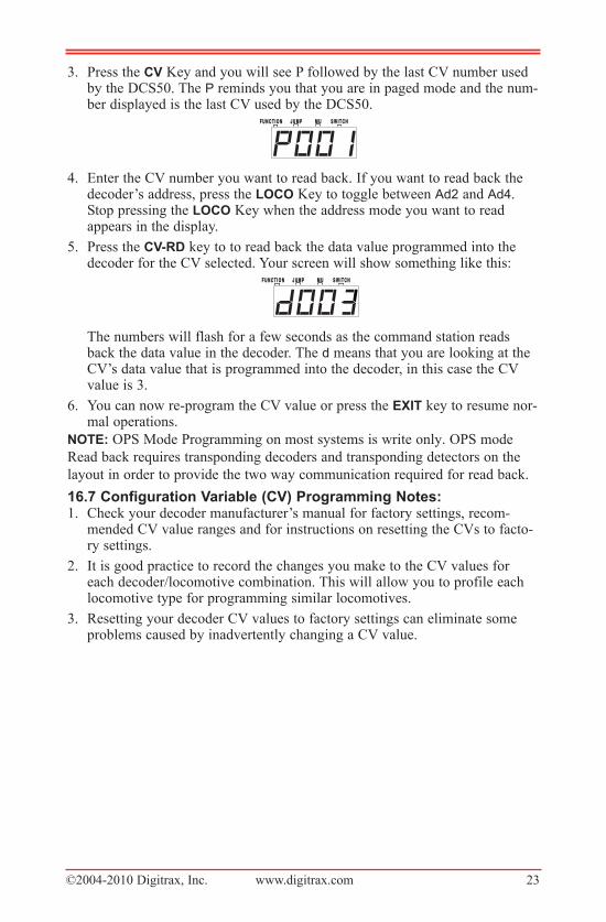
3. Press the Cv Key and you will see P followed by the last CV number usedby the DCS50. The P reminds you that you are in paged mode and the num-ber displayed is the last CV used by the DCS50.
4. Enter the CV number you want to read back. If you want to read back thedecoder’s address, press the lOCO Key to toggle between Ad2 and Ad4.Stop pressing the lOCO Key when the address mode you want to readappears in the display.
5. Press the Cv-rD key to to read back the data value programmed into thedecoder for the CV selected. Your screen will show something like this:
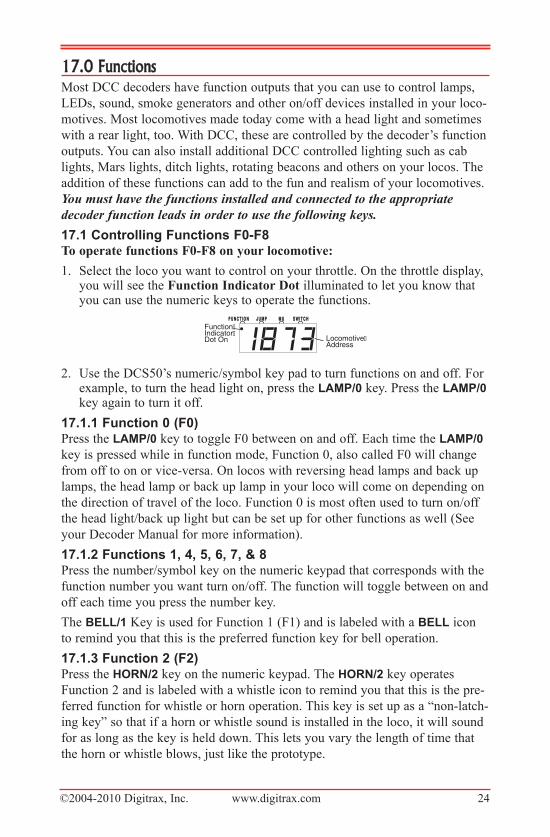
The numbers will flash for a few seconds as the command station readsback the data value in the decoder. The d means that you are looking at theCV’s data value that is programmed into the decoder, in this case the CVvalue is 3.
6. You can now re-program the CV value or press the exit key to resume nor-mal operations.
nOte: OPS Mode Programming on most systems is write only. OPS mode
Read back requires transponding decoders and transponding detectors on the
layout in order to provide the two way communication required for read back.
16.7�Configuration�variable�(Cv)�programming�notes:1. Check your decoder manufacturer’s manual for factory settings, recom-
mended CV value ranges and for instructions on resetting the CVs to facto-ry settings.
2. It is good practice to record the changes you make to the CV values foreach decoder/locomotive combination. This will allow you to profile eachlocomotive type for programming similar locomotives.
3. Resetting your decoder CV values to factory settings can eliminate someproblems caused by inadvertently changing a CV value.
S W I T C HS W I T C HM UM UJ U M PJ U M PF U N C T I O NF U N C T I O N
S W I T C HS W I T C HM UM UJ U M PJ U M PF U N C T I O NF U N C T I O N
©2004-2010 Digitrax, Inc. www.digitrax.com 24
17.0 FunctionsMost DCC decoders have function outputs that you can use to control lamps,
LEDs, sound, smoke generators and other on/off devices installed in your loco-
motives. Most locomotives made today come with a head light and sometimes
with a rear light, too. With DCC, these are controlled by the decoder’s function
outputs. You can also install additional DCC controlled lighting such as cab
lights, Mars lights, ditch lights, rotating beacons and others on your locos. The
addition of these functions can add to the fun and realism of your locomotives.
You must have the functions installed and connected to the appropriate
decoder function leads in order to use the following keys.
17.1�Controlling�Functions�F0-F8To operate functions F0-F8 on your locomotive:
1. Select the loco you want to control on your throttle. On the throttle display,you will see the Function Indicator Dot illuminated to let you know thatyou can use the numeric keys to operate the functions.
2. Use the DCS50’s numeric/symbol key pad to turn functions on and off. Forexample, to turn the head light on, press the laMp/0 key. Press the laMp/0key again to turn it off.
17.1.1�Function�0�(F0)Press the laMp/0 key to toggle F0 between on and off. Each time the laMp/0
key is pressed while in function mode, Function 0, also called F0 will change
from off to on or vice-versa. On locos with reversing head lamps and back up
lamps, the head lamp or back up lamp in your loco will come on depending on
the direction of travel of the loco. Function 0 is most often used to turn on/off
the head light/back up light but can be set up for other functions as well (See
your Decoder Manual for more information).
17.1.2�Functions�1,�4,�5,�6,�7,�&�8Press the number/symbol key on the numeric keypad that corresponds with the
function number you want turn on/off. The function will toggle between on and
off each time you press the number key.
The Bell/1 Key is used for Function 1 (F1) and is labeled with a Bell icon
to remind you that this is the preferred function key for bell operation.
17.1.3�Function�2�(F2)Press the hOrn/2 key on the numeric keypad. The hOrn/2 key operates
Function 2 and is labeled with a whistle icon to remind you that this is the pre-
ferred function for whistle or horn operation. This key is set up as a “non-latch-
ing key” so that if a horn or whistle sound is installed in the loco, it will sound
for as long as the key is held down. This lets you vary the length of time that
the horn or whistle blows, just like the prototype.
S W I T C HS W I T C HM UM UJ U M PJ U M PF U N C T I O NF U N C T I O NFunction Indicator Dot On Locomotive
Address
©2004-2010 Digitrax, Inc. www.digitrax.com 25
If you want Function 2 to remain on:1. Press and hold the hOrn/2 key.2. Press and hold the exit key.3. Release the hOrn/2 key4. Release the exit key.
17.1.4�Function�3�(F3)COupler/3 key operates Function 3 and is labeled with a COupler icon to
remind you that this is the preferred function key for future coupler operation.
The DCS50 treats Function 3 is a normal on/off function unless you set it up as
a non-latching function like Function 2. This means that F3 can be used either
as a normal function or to control a function that requires a momentary activa-
tion like some couplers.
To set up Function 3 as a non-latching function, set the DCS50’s Option
Switch 6 to closed as follows:1. Press the prOg key. The last programming mode used by the DCS50 will
be displayed.
2. Press the SwitCh key. The display shows the last switch used by theDCS50.
3. Use the numeric key pad to enter 6. This tells the system that you want tochange Option Switch 6, the OpSw that controls whether F3 is latching ornon-latching.
4. Press the c/- key to make F3 non-latching. OR Press the t/+ key to make F3a normal latching on/off function.
5. Press the Exit Key to complete the set up of F3 as a non-latching key. Thiswill cause the COupler/3 key to operate Function 3 as a non-latchingfunction for this particular DCS50 and any attached Jump™ Throttles.Other throttles (including other DCS50s) in the system will not be affected.
17.2�Function�Operation�troubleshootingIf the function you want to operate does not respond, check the following:1. Is Track Status on? If not press the pOwer key to turn it on.
2. Did you select the correct loco? If not, select it now.
3. Is the function you want to use installed in the loco? If not, you may needto install it. Most new locos have a head lamp/backup lamp installed, butmost do not have any additional lights or sounds installed.
4. Change the position of the Direction Control Lever and see if the lampcomes on in the other direction. If the normal direction of travel feature inthe decoder loco is set for the opposite of what you were expecting, youwill see the head lamp operating in what you expected to be the reversedirection and vice versa for the back up lamp. See your Decoder Manual forinformation about how to change the Normal Direction of Travel (NDOT).
NOTE: Functions F9-F12 can be accessed when using DT400 or DT402series throttles with your DCS50.
S W I T C HS W I T C HM UM UJ U M PJ U M PF U N C T I O NF U N C T I O N
Set OpSw 006 to t to make F3 non-latching.
©2004-2010 Digitrax, Inc. www.digitrax.com 26
18.0�Mu�(Multiple�unit)�Operations
It is not uncommon to see two, three or even four diesel locos pulling in con-
sist at the front of a train. Sometimes, there is a locomotive added in the middle
of the train or at the end of the train to give “helper service” to the head end
locomotives. This is called Multiple Unit Operation or MU operation. With
DCC, each locomotive is separately controlled. But in the case of MUing we
would like to have more than one locomotive address controlled by a single
throttle to simplify MU operation.
Your DCS50 uses universal consisting to make MU operations simple and easy
to do. This is the most flexible and realistic method of MUing available. You
can add any locomotive to your MU, no matter what kind of DCC decoder is in
your loco. You can even add an analog loco to your MU. You can add a loco-
motive to an MU in either orientation and in any physical location in the train.
When you send commands to the MU you use the address of the TOP locomo-
tive to control the entire MU and the command station handles the rest of the
commands to the other locomotives in the MU. As the address you will use to
control the consist is not necessarily the address of the lead or head end loco,
we use the term “TOP” for this special address. The TOP address can also be
the train number.
You will not be able change the speed or direction of any individual loco that is
part of an MU. Locomotive speed and direction for all locos in the MU are
controlled by the TOP address.
18.1�adding�a�locomotive�to�an�MuTo MU two addresses together with the DCS50:
1. Choose two locos you want to MU together. Place them on the track. Makesure that both locos that will be part of the MU are headed in the samephysical direction. Select and run the first loco to determine which way it isheaded. Then select the other loco and run it in the same physical direction.
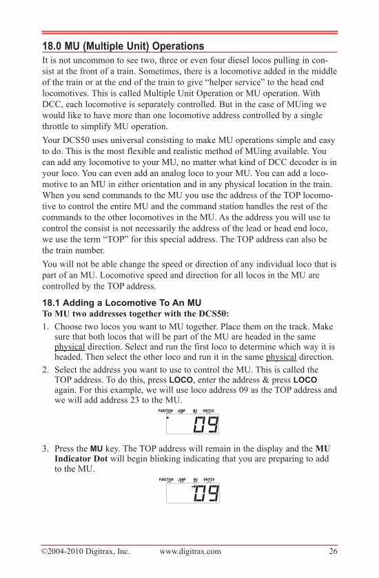
2. Select the address you want to use to control the MU. This is called theTOP address. To do this, press lOCO, enter the address & press lOCOagain. For this example, we will use loco address 09 as the TOP address andwe will add address 23 to the MU.
3. Press the Mu key. The TOP address will remain in the display and the MUIndicator Dot will begin blinking indicating that you are preparing to addto the MU.
S W I T C HS W I T C HM UM UJ U M PJ U M PF U N C T I O NF U N C T I O N
S W I T C HS W I T C HM UM UJ U M PJ U M PF U N C T I O NF U N C T I O N
©2004-2010 Digitrax, Inc. www.digitrax.com 27
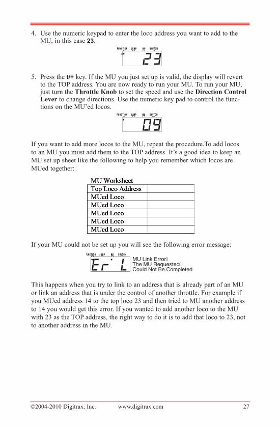
4. Use the numeric keypad to enter the loco address you want to add to theMU, in this case 23.
5. Press the t/+ key. If the MU you just set up is valid, the display will revertto the TOP address. You are now ready to run your MU. To run your MU,just turn the Throttle Knob to set the speed and use the Direction ControlLever to change directions. Use the numeric key pad to control the func-tions on the MU’ed locos.
If you want to add more locos to the MU, repeat the procedure.To add locos
to an MU you must add them to the TOP address. It’s a good idea to keep an
MU set up sheet like the following to help you remember which locos are
MUed together:
If your MU could not be set up you will see the following error message:
This happens when you try to link to an address that is already part of an MU
or link an address that is under the control of another throttle. For example if
you MUed address 14 to the top loco 23 and then tried to MU another address
to 14 you would get this error. If you wanted to add another loco to the MU
with 23 as the TOP address, the right way to do it is to add that loco to 23, not
to another address in the MU.
S W I T C HS W I T C HM UM UJ U M PJ U M PF U N C T I O NF U N C T I O N
MU Link Error The MU Requested Could Not Be Completed
S W I T C HS W I T C HM UM UJ U M PJ U M PF U N C T I O NF U N C T I O N
S W I T C HS W I T C HM UM UJ U M PJ U M PF U N C T I O NF U N C T I O N
©2004-2010 Digitrax, Inc. www.digitrax.com 28
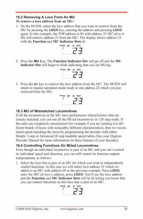
18.2�removing�a�loco�From�an�MuTo remove a loco address from an MU:
1. On the DCS50, select the loco address that you want to remove from theMU by pressing the lOCO key, entering the address and pressing lOCOagain. In this example, the TOP address is 09 with address 23 MU’ed to it.We will remove address 23 from the MU. The display shows address 23with the Function and MU Indicator Dots lit.
2. Press the Mu Key. The Function Indicator Dot will go off and the MUIndicator Dot will begin to blink indicating that you are MUing.
3. Press the c/- key to remove the loco address from the MU. The DCS50 willreturn to regular operation mode ready to run address 23 which you justremoved from the MU.
18.3�Mu�of�Mismatched�locomotivesIf all the locomotives in the MU have performance characteristics that are
closely matched, you can run all the MUed locomotives in 128 step mode. If
the units are completely mismatched (for example if you are running two dif-
ferent brands of locos with noticeably different characteristics), then we recom-
mend speed matching the locos by programming the decoder with either
Simple 3 step or Advanced 28 step loadable speed tables (See your Digitrax
Decoder Manual for more information on these features of your decoder).
18.4�Controlling�Functions�On�Mued�locomotivesEven though an individual locomotive is part of an MU and you can’t control
its individual speed and direction, you can still control its function outputs
independently as follows:
1. Select the loco that is part of an MU for which you wish to independentlycontrol functions. In this case we will select loco address 23 which weadded to an MU with address 09 in the previous example. Press lOCO,enter the MU’ed loco’s address, press lOCO. You’ll see the loco addressand the Function and MU Indicator Dots will be lit letting you know thatyou can control functions on this loco that is part of an MU.
S W I T C HS W I T C HM UM UJ U M PJ U M PF U N C T I O NF U N C T I O N
S W I T C HS W I T C HM UM UJ U M PJ U M PF U N C T I O NF U N C T I O N
S W I T C HS W I T C HM UM UJ U M PJ U M PF U N C T I O NF U N C T I O N
S W I T C HS W I T C HM UM UJ U M PJ U M PF U N C T I O NF U N C T I O N
©2004-2010 Digitrax, Inc. www.digitrax.com 29
2. Use the numeric keypad to control the functions. The changes will takeeffect immediately if the locomotives are moving, otherwise changes willtake effect when you reselect the TOP address on the throttle.
3. When you are finished turning functions on or off for the consisted loco,simply select the TOP address and resume running the MU.
4. Remember, you will not be able change the speed or direction of any indi-vidual loco that is part of an MU. Locomotive speed and direction for alllocos in the MU are controlled by the TOP address.
Note: You can also control the functions of a MUed loco from a differentthrottle that is connected into LocoNet or with one of the Jump ports of theDCS50 (see Section 25.2 for setting up the Jump Ports), leaving the TOPlocomotive selected on the main throttle of the DCS50. Function statechanges will take effect immediately whether or not the loco is moving.
19.0 Stealing: When An Address Is Running on Another ThrottleDigitrax systems do not allow more than one user to select and run the same
locomotive address unless the loco is “stolen” by the new user. When an
address is receiving commands from more than one throttle, it may seem to be
out of control.
Stealing is a safety interlock that prevents operators from automatically taking
control of locos that are already selected and being run on another throttle.
Occasionally you may need to override this interlock to gain control of a loco.
This override is called stealing and will result in having a single loco address
selected on two different throttles at the same time.
For example, if you are running a train on a particular loco address at 25%
throttle and another operator is running the same loco address but sending a
stop command you will see the train stop unexpectedly. From your perspective,
the train is not behaving correctly so you would probably increase your throttle
setting and the train would begin moving again. From the other operators per-
spective, the train is moving again so it is not responding to his/her commands.
Since the other operator wants to stop the train, he or she is likely to send the
command again since the train is now moving again. As you can see, having
two engineers on the same train can give strange operations. For this reason,
Digitrax interlocks locomotive selection so that you can’t take control of a loco
that is already selected on another throttle without “stealing” the address.
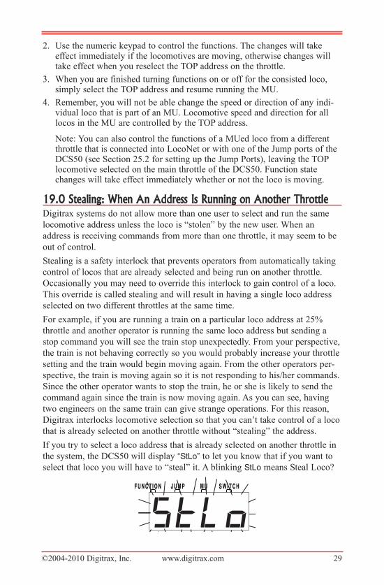
If you try to select a loco address that is already selected on another throttle in
the system, the DCS50 will display “StLo” to let you know that if you want to
select that loco you will have to “steal” it. A blinking StLo means Steal Loco?
S W I T C HS W I T C HM UM UJ U M PJ U M PF U N C T I O NF U N C T I O N
©2004-2010 Digitrax, Inc. www.digitrax.com 30
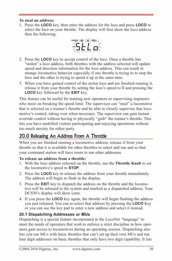
To steal an address:1. Press the lOCO key, then enter the address for the loco and press lOCO to
select the loco on your throttle. The display will first show the loco addressthen the following:
2. Press the lOCO key to accept control of the loco. Once a throttle has“stolen” a loco address, both throttles with the address selected will updatespeed and direction information for the loco address. This can result instrange locomotive behavior especially if one throttle is trying to to stop theloco and the other is trying to speed it up at the same time.
3. When you have gained control of the stolen loco and are finished running it,release it from your throttle by setting the loco’s speed to 0 and pressing thelOCO key followed by the exit key.
This feature can be useful for training new operators or supervising engineers
who insist on breaking the speed limit. The supervisor can “steal” a locomotive
that is selected on a trainee’s throttle and be able to closely supervise that loco-
motive’s control, taking over when necessary. The supervisor can gain instant
override control without having to physically “grab” the trainee’s throttle. This
lets you have unskilled visitors participating and enjoying operations without
too much anxiety for either party.
20.0 Releasing An Address From A ThrottleWhen you are finished running a locomotive address, release if from your
throttle so that it is available for other throttles to select and run and so that
your command station will have room to run other addresses.
To release an address from a throttle:1. With the loco address selected on the throttle, use the Throttle Knob to set
the locomotive’s speed to StOp.
2. Press the lOCO key to release the address from your throttle immediately.The address will begin to flash in the display.
3. Press the exit key to dispatch the address on the throttle and the locomo-tive will be released to the system and marked as a dispatched address. YourDCS50’s display will show Loco.
4. If you press the lOCO key again, the throttle will begin flashing the addressyou just released. You can re-select that address by pressing the lOCO Keyor you can use the key pad to enter a new address and select it instead.
20.1�Dispatching�addresses�or�MusDispatching is a special feature incorporated in the LocoNet “language” to
meet the needs of operators that wish to enforce a strict discipline in how oper-
ators gain access to locomotives during an operating session. Dispatching also
lets you run MUs with basic throttles that can’t set up their own MUs and run
four digit addresses on basic throttles that only have two digit capability. It lets
S W I T C HS W I T C HM UM UJ U M PJ U M PF U N C T I O NF U N C T I O N
©2004-2010 Digitrax, Inc. www.digitrax.com 31
you have newcomers run trains on the layout without giving them access to the
entire operation.
When you dispatch a locomotive address or MU to your LocoNet system, you
make it available to be acquired by another throttle. Only one address at a time
can be marked as a dispatched address in the system. The dispatched loco
address is acquired by the first throttle to request it by pressing the aCQ key to
select it for use on that throttle. See the UT1, UT2 and BT2 throttle Manuals
for complete dispatch operation instructions.
To dispatch a locomotive address using a the DCS50:
1. Press the lOCO key, enter the address you want to dispatch.
2. Press to the exit key to dispatch it to your LocoNet system, that’s all thereis to it!
The dispatched address can be a single locomotive address, either two digit or
four digit, or an MU. The TOP locomotive in an MU can be dispatched to
transfer control of the entire consist to another throttle.
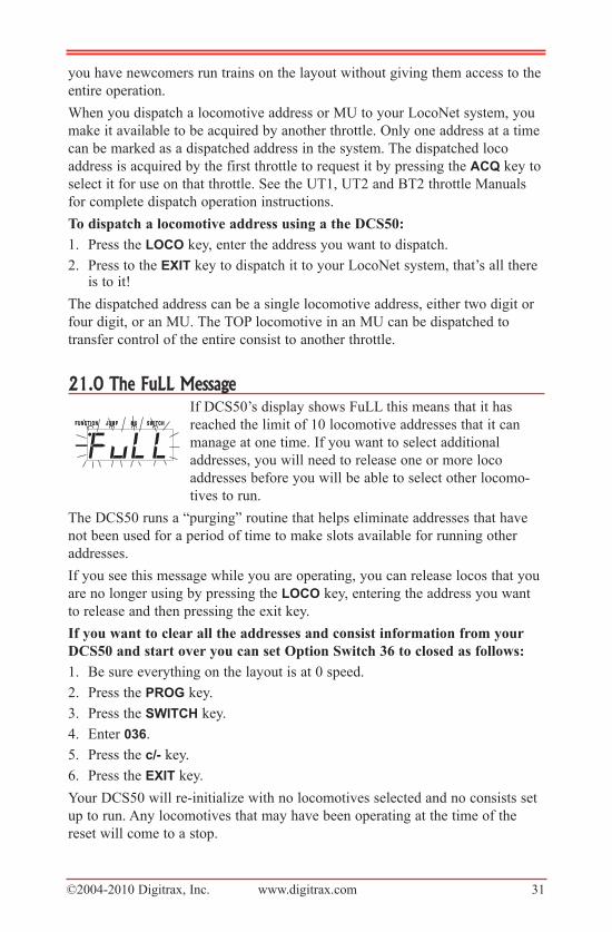
21.0 The FuLL MessageIf DCS50’s display shows FuLL this means that it has
reached the limit of 10 locomotive addresses that it can
manage at one time. If you want to select additional
addresses, you will need to release one or more loco
addresses before you will be able to select other locomo-
tives to run.
The DCS50 runs a “purging” routine that helps eliminate addresses that have
not been used for a period of time to make slots available for running other
addresses.
If you see this message while you are operating, you can release locos that you
are no longer using by pressing the lOCO key, entering the address you want
to release and then pressing the exit key.
If you want to clear all the addresses and consist information from your
DCS50 and start over you can set Option Switch 36 to closed as follows:
1. Be sure everything on the layout is at 0 speed.
2. Press the prOg key.
3. Press the SwitCh key.
4. Enter 036.
5. Press the c/-�key.
6. Press the exit key.
Your DCS50 will re-initialize with no locomotives selected and no consists set
up to run. Any locomotives that may have been operating at the time of the
reset will come to a stop.
S W I T C HS W I T C HM UM UJ U M PJ U M PF U N C T I O NF U N C T I O N
©2004-2010 Digitrax, Inc. www.digitrax.com 32
22.0 DCS50 Error MessagesThe DCS50 displays three types of error messages:
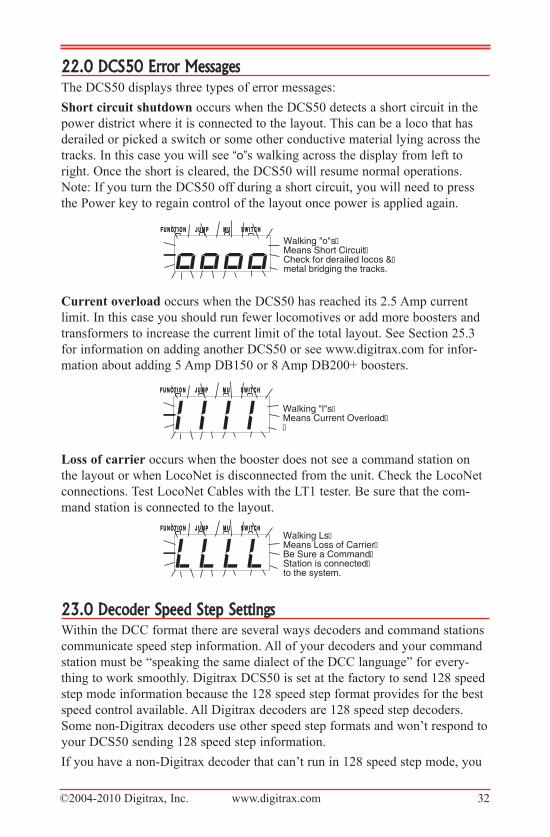
Short circuit shutdown occurs when the DCS50 detects a short circuit in the
power district where it is connected to the layout. This can be a loco that has
derailed or picked a switch or some other conductive material lying across the
tracks. In this case you will see “o”s walking across the display from left to
right. Once the short is cleared, the DCS50 will resume normal operations.
Note: If you turn the DCS50 off during a short circuit, you will need to press
the Power key to regain control of the layout once power is applied again.
Current overload occurs when the DCS50 has reached its 2.5 Amp current
limit. In this case you should run fewer locomotives or add more boosters and
transformers to increase the current limit of the total layout. See Section 25.3
for information on adding another DCS50 or see www.digitrax.com for infor-
mation about adding 5 Amp DB150 or 8 Amp DB200+ boosters.
Loss of carrier occurs when the booster does not see a command station on
the layout or when LocoNet is disconnected from the unit. Check the LocoNet
connections. Test LocoNet Cables with the LT1 tester. Be sure that the com-
mand station is connected to the layout.
23.0 Decoder Speed Step SettingsWithin the DCC format there are several ways decoders and command stations
communicate speed step information. All of your decoders and your command
station must be “speaking the same dialect of the DCC language” for every-
thing to work smoothly. Digitrax DCS50 is set at the factory to send 128 speed
step mode information because the 128 speed step format provides for the best
speed control available. All Digitrax decoders are 128 speed step decoders.
Some non-Digitrax decoders use other speed step formats and won’t respond to
your DCS50 sending 128 speed step information.
If you have a non-Digitrax decoder that can’t run in 128 speed step mode, you
S W I T C HS W I T C HM UM UJ U M PJ U M PF U N C T I O NF U N C T I O NWalking Ls Means Loss of Carrier Be Sure a Command Station is connected to the system.
S W I T C HS W I T C HM UM UJ U M PJ U M PF U N C T I O NF U N C T I O N
Walking "l"s Means Current Overload
S W I T C HS W I T C HM UM UJ U M PJ U M PF U N C T I O NF U N C T I O N
Walking "o"s Means Short Circuit Check for derailed locos & metal bridging the tracks.
©2004-2010 Digitrax, Inc. www.digitrax.com 33
can change the number of speed steps the DCS50 sends to that decoder so that
you will be able to control the decoder. This is called status editing the
decoder. When you status edit a decoder, the DCS50 will send a different for-
mat to that decoder without affecting the 128 speed step operation of the
Digitrax and other 128 speed step decoders on the layout.
NOTE: Status editing does not reprogram anything in the decoder. It only
changes the messages that are sent to the decoder by the command station.
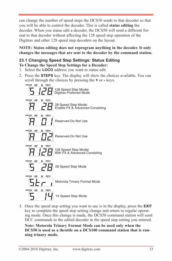
23.1�Changing�Speed�Step�Settings:�Status�editingTo Change the Speed Step Settings for a Decoder:1. Select the lOCO address you want to status edit.
2. Press the StepS key. The display will show the choices available. You canscroll through the choices by pressing the + or - keys.
3. Once the speed step setting you want to use is in the display, press the exitkey to complete the speed step setting change and return to regular operat-ing mode. Once this change is made, the DCS50 command station will sendDCC commands to the edited decoder in the speed step setting you entered.
Note: Motorola Trinary Format Mode can be used only when theDCS50 is used as a throttle on a DCS100 command station that is run-ning trinary mode.
S W I T C HS W I T C HM UM UJ U M PJ U M PF U N C T I O NF U N C T I O N
14 Speed Step Mode
S W I T C HS W I T C HM UM UJ U M PJ U M PF U N C T I O NF U N C T I O N
Motorola Trinary Format Mode
S W I T C HS W I T C HM UM UJ U M PJ U M PF U N C T I O NF U N C T I O N
28 Speed Step Mode
S W I T C HS W I T C HM UM UJ U M PJ U M PF U N C T I O NF U N C T I O N
128 Speed Step Mode With FX & Advanced Consisting
S W I T C HS W I T C HM UM UJ U M PJ U M PF U N C T I O NF U N C T I O N
Reserved-Do Not Use
S W I T C HS W I T C HM UM UJ U M PJ U M PF U N C T I O NF U N C T I O N
Reserved-Do Not Use
S W I T C HS W I T C HM UM UJ U M PJ U M PF U N C T I O NF U N C T I O N
28 Speed Step Mode Enable FX & Advanced Consisting
S W I T C HS W I T C HM UM UJ U M PJ U M PF U N C T I O NF U N C T I O N
128 Speed Step Mode Digitrax Preferred Mode
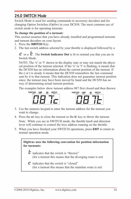
©2004-2010 Digitrax, Inc. www.digitrax.com 34
24.0 SWITCH ModeSwitch Mode is used for sending commands to accessory decoders and for
changing Option Switches (OpSw) in your DCS50. The most common use of
switch mode is for operating turnouts.
To change the position of a turnout:
This section assumes that you have already installed and programmed turnouts
and turnout decoders on your layout.1. Press the SwitCh Key.
2. The last switch address selected by your throttle is displayed followed by a
or a . The Switch Indicator Dot is lit to remind you that you are in
Switch Mode.
NOTE: The “c” or “t” shown in the display may or may not match the physi-cal position of the turnout selected. If the “c” or “t” is flashing, it means thatthe DCS50 has no information about the current position of the turnout. Ifthe c or t is steady it means that the DCS50 remembers the last commandsent by it to that turnout. This indication does not guarantee turnout positionsince, the turnout may have been moved by hand and the DCS50 has noway of determining actual turnout position.
The examples below show turnout address 087 first closed and then thrown
3. Use the numeric keypad to enter the turnout address for the turnout youwant to change.
4. Press the c/- key to close the turnout or the t/- key to throw the turnout.
Note: While you are in SWITCH mode, the throttle knob and directionlever will continue to control the loco address running on the throttle.
5. When you have finished your SWITCH operations, press exit to return tonormal operation mode.
S W I T C HS W I T C HM UM UJ U M PJ U M PF U N C T I O NF U N C T I O N S W I T C HS W I T C HM UM UJ U M PJ U M PF U N C T I O NF U N C T I O N
Digitrax uses the following convention for position information
for turnouts:
indicates that the switch is “thrown”
(for a turnout this means that the diverging route is set)
indicates that the switch is “closed”
(for a turnout this means that the mainline route is set)
©2004-2010 Digitrax, Inc. www.digitrax.com 35
25.0 Adding Throttles: LocoNet & Jump™ PortsSooner or later you will probably want to have one or more other people run
trains with you. This means you’ll have to add more throttles to your DCS50.
You can add any LocoNet throttle to your DCS50 or you can use one or two
smooth DC power packs as Jump throttles.
25.1�adding�loconet�throttles�to�your�DCS50Any LocoNet throttle can be used with your DCS50. Simply plug the LocoNet
throttle into either LocoNet port on the back of your DCS50 or into any
LocoNet or Throttle Jack anywhere on your LocoNet system. If you want to be
able to plug in a throttle at a remote location, we recommend using a UP5
Universal panel.
Your DCS50 can handle up to 10 LocoNet Throttles. If you need to run more
than 10 throttles, you can move up to a Super Empire Builder II and be able to
run up to 22 throttles or to a Super Chief II with the capacity for running up to
120 throttles. You can continue to use your DCS50 as a throttle and booster
with either set on your Digitrax LocoNet system.
25.2�Jump™�ports:�using�a�Smooth�DC�power�pack as�an
additional�throttleDCS50’s Jump A & B ports can host two DC power packs as additional throt-
tles. Begin with an operating DCS50 attached to your layout. Hook up one or
two smooth DC power packs as shown in the following illustration. This con-
figuration gives you three throttles to control three loco addresses.
1. The throttle knob and direction lever on your DCS50 is called the LocalThrottle.
2. The throttle and direction controls on each of the smooth DC power packsyou are using are called respectively, Jump 1 and Jump 2.
3. Press the JuMp key to cycle from the Local Throttle to Jump 1 to Jump 2and back to the Local Throttle. The Jump Indicator Dot tells you whichthrottle functions are being addressed by the DCS50 keyboard.No Jump Indicator Dot - the Local ThrottleSteady Jump Indicator Dot - Jump 1 Blinking Jump Indicator Dot - Jump 2
4. The functions for each throttle are controlled by the DCS50’s key pad whenthe Jump Indicator Dot for that throttle is displayed (see step 3).
5. To access function controls for each throttle, simply press the JuMp key tocycle among the three throttles.
6. When the throttle’s Jump Indicator Dot for which you want to controlfunctions appears on the display, use the DCS50’s keypad to change thefunctions. The throttle knobs and direction controls for all three throttleswill continue to control the loco selected on them while you are workingwith function controls on any of the three throttles.
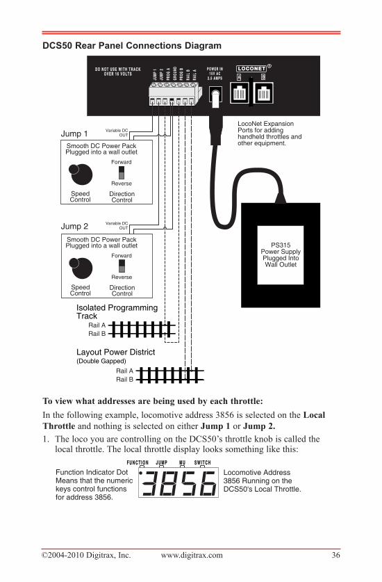
©2004-2010 Digitrax, Inc. www.digitrax.com 36
DCS50�rear�panel�Connections Diagram
To view what addresses are being used by each throttle:
In the following example, locomotive address 3856 is selected on the Local
Throttle and nothing is selected on either Jump 1 or Jump 2.
1. The loco you are controlling on the DCS50’s throttle knob is called thelocal throttle. The local throttle display looks something like this:
S W I T C HS W I T C HM UM UJ U M PJ U M PF U N C T I O NF U N C T I O N
Locomotive Address 3856 Running on the DCS50's Local Throttle.
Function Indicator DotMeans that the numerickeys control functions for address 3856.
BAJUM
P 1
JUM
P1
GROU
NDGR
OUND
RAIL
BRA
ILB
JUM
P 2
JUM
P2
PROG
APR
OGA
RAIL
ARA
ILA
PROG
BPR
OGB L O C O N E TL O C O N E T
RP O W E R I NP O W E R I N
1 5 V A C1 5 V A C2 . 5 A M P S2 . 5 A M P S
D O N O T U S E W I T H T R A C KD O N O T U S E W I T H T R A C KO V E R 1 6 V O L T SO V E R 1 6 V O L T S
PS315Power SupplyPlugged IntoWall Outlet
Layout Power District (Double Gapped)
Rail A
Rail B
LocoNet ExpansionPorts for addinghandheld throttles and other equipment.
SpeedControl
DirectionControl
Forward
Reverse
Smooth DC Power PackPlugged into a wall outlet
Jump 1
Jump 2
SpeedControl
DirectionControl
Forward
Reverse
Smooth DC Power PackPlugged into a wall outlet
DCS50 Rear Panel Hook Up Diagram
Isolated ProgrammingTrack
Rail A
Rail B
Variable DCOUT
Variable DCOUT
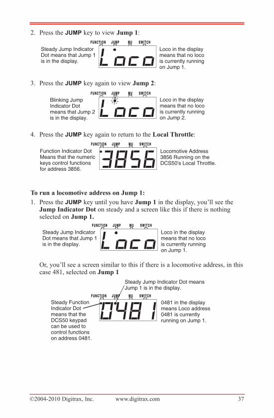
©2004-2010 Digitrax, Inc. www.digitrax.com 37
2. Press the JuMp key to view Jump 1:
3. Press the JuMp key again to view Jump 2:
4. Press the JuMp key again to return to the Local Throttle:
To run a locomotive address on Jump 1:
1. Press the JuMp key until you have Jump 1 in the display, you’ll see theJump Indicator Dot on steady and a screen like this if there is nothingselected on Jump 1.
Or, you’ll see a screen similar to this if there is a locomotive address, in thiscase 481, selected on Jump 1
S W I T C HS W I T C HM UM UJ U M PJ U M PF U N C T I O NF U N C T I O N
Steady Jump Indicator Dot means Jump 1 is in the display.
0481 in the display means Loco address 0481 is currently running on Jump 1.
Steady Function Indicator Dotmeans that the DCS50 keypadcan be used to control functionson address 0481.
S W I T C HS W I T C HM UM UJ U M PJ U M PF U N C T I O NF U N C T I O N
Steady Jump Indicator Dot means that Jump 1 is in the display.
Loco in the displaymeans that no locois currently runningon Jump 1.
S W I T C HS W I T C HM UM UJ U M PJ U M PF U N C T I O NF U N C T I O N
Locomotive Address 3856 Running on the DCS50's Local Throttle.
Function Indicator DotMeans that the numerickeys control functions for address 3856.
S W I T C HS W I T C HM UM UJ U M PJ U M PF U N C T I O NF U N C T I O NBlinking Jump Indicator Dotmeans that Jump 2is in the display.
Loco in the displaymeans that no locois currently runningon Jump 2.
S W I T C HS W I T C HM UM UJ U M PJ U M PF U N C T I O NF U N C T I O N
Steady Jump Indicator Dot means that Jump 1 is in the display.
Loco in the displaymeans that no locois currently runningon Jump 1.
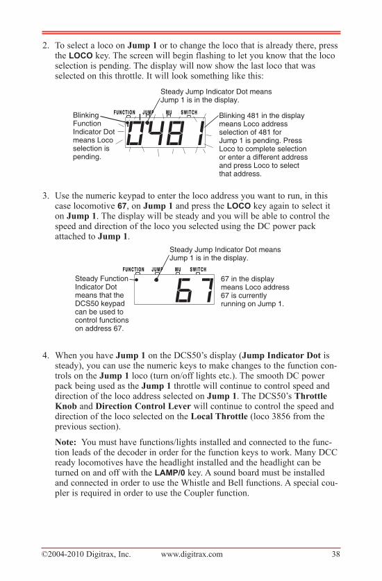
©2004-2010 Digitrax, Inc. www.digitrax.com 38
2. To select a loco on Jump 1 or to change the loco that is already there, pressthe lOCO key. The screen will begin flashing to let you know that the locoselection is pending. The display will now show the last loco that wasselected on this throttle. It will look something like this:
3. Use the numeric keypad to enter the loco address you want to run, in thiscase locomotive 67, on Jump 1 and press the lOCO key again to select iton Jump 1. The display will be steady and you will be able to control thespeed and direction of the loco you selected using the DC power packattached to Jump 1.
4. When you have Jump 1 on the DCS50’s display (Jump Indicator Dot issteady), you can use the numeric keys to make changes to the function con-trols on the Jump 1 loco (turn on/off lights etc.). The smooth DC powerpack being used as the Jump 1 throttle will continue to control speed anddirection of the loco address selected on Jump 1. The DCS50’s ThrottleKnob and Direction Control Lever will continue to control the speed anddirection of the loco selected on the Local Throttle (loco 3856 from theprevious section).
Note: You must have functions/lights installed and connected to the func-tion leads of the decoder in order for the function keys to work. Many DCCready locomotives have the headlight installed and the headlight can beturned on and off with the laMp/0 key. A sound board must be installedand connected in order to use the Whistle and Bell functions. A special cou-pler is required in order to use the Coupler function.
S W I T C HS W I T C HM UM UJ U M PJ U M PF U N C T I O NF U N C T I O N
Steady Jump Indicator Dot means Jump 1 is in the display.
67 in the display means Loco address 67 is currently running on Jump 1.
Steady Function Indicator Dotmeans that the DCS50 keypadcan be used to control functionson address 67.
S W I T C HS W I T C HM UM UJ U M PJ U M PF U N C T I O NF U N C T I O N
Steady Jump Indicator Dot means Jump 1 is in the display.
Blinking �Function Indicator Dotmeans Loco �selection is �pending.
Blinking 481 in the display �means Loco address �selection of 481 for �Jump 1 is pending. Press �Loco to complete selection or enter a different address �and press Loco to selectthat address.
©2004-2010 Digitrax, Inc. www.digitrax.com 39
To run a locomotive address on Jump 2:
1. Press the JuMp key until you see the Jump 2 display on the DCS50. Youwill see the Jump Indicator Dot flashing and either Loco or the addresscurrently being run on Jump 2 in the display.
2. To select a different locomotive address, press the lOCO�key, the displaynumbers will start to blink. Using the numeric keypad, enter the locoaddress you want to select and press the lOCO key again to complete theselection process. The display numbers will stop blinking.
3. When you have Jump 2 on the DCS50’s display, you will control the loco-motive’s speed and direction on Jump 2 with the DC power pack and youcan use the DCS50’s numeric keys to make changes to the functions on theJump 2 loco. The DCS50’s throttle knob and direction lever will continueto control the speed and direction of the loco selected on the local throttle.The Jump 1 power pack will continue to control speed and direction of theloco address selected on the Jump 1 throttle.
25.3�adding�another�DCS50 to�your�layoutSince each system, no matter how large, needs only one command station, you
need only one DCS50 (or other Digitrax Command Station) performing this
function. Any additional DCS50 must be converted to a booster by changing
the Option Switch settings as described below. (Note, when using the DCS50
as a booster, the programming outputs are disabled.) The command station
determines the total number of locomotive addresses your system can handle:
Zephyr up to 10, Empire Builder (DB150) up to 22 and Chief (DCS100) up to
120. Adding a booster does not change the number of addresses available to the
command station, but you do gain additional power to run trains. When you
add a DCS50 to an existing system you gain additional power (2.5A) for con-
trolling power districts or reversing sections AND you gain an additional three
throttles to control trains: the local throttle and the two jump port throttles.
To set up a DCS50 to run as a booster and throttle without command sta-
tion capabilities:
1. Press the prOg key. The display shows the last programming mode usedby the DCS50.
2. Press the SwitCh key. The display shows the last switch used by theDCS50.The Switch Indicator Dot will start blinking to indicate you are inOption Switch Mode.
S W I T C HS W I T C HM UM UJ U M PJ U M PF U N C T I O NF U N C T I O N
Blinking Jump Indicator Dot meansJump 2 is in the display.
08 in the display means Loco address 08 is currently running on Jump 2.
Steady Function Indicator Dotmeans that the DCS50 keypadcan be used to control functionson address 08.
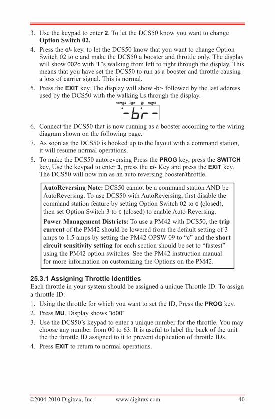
©2004-2010 Digitrax, Inc. www.digitrax.com 40
3. Use the keypad to enter 2. To let the DCS50 know you want to changeOption Switch 02.
4. Press the c/- key. to let the DCS50 know that you want to change OptionSwitch 02 to c and make the DCS50 a booster and throttle only. The displaywill show 002c with “L”s walking from left to right through the display. Thismeans that you have set the DCS50 to run as a booster and throttle causinga loss of carrier signal. This is normal.
5. Press the exit key. The display will show -br- followed by the last addressused by the DCS50 with the walking Ls through the display.
6. Connect the DCS50 that is now running as a booster according to the wiringdiagram shown on the following page.
7. As soon as the DCS50 is hooked up to the layout with a command station,it will resume normal operations.
8. To make the DCS50 autoreversing Press the prOg key, press the SwitCh
key, Use the keypad to enter 3, press the c/- Key and press the exit key.The DCS50 will now run as an auto reversing booster/throttle.
25.3.1�assigning�throttle�identitiesEach throttle in your system should be assigned a unique Throttle ID. To assign
a throttle ID:
1. Using the throttle for which you want to set the ID, Press the prOg key.
2. Press Mu. Display shows “id00”
3. Use the DCS50’s keypad to enter a unique number for the throttle. You maychoose any number from 00 to 63. It is useful to label the back of the unitthe the throttle ID assigned to it to prevent duplication of throttle IDs.
4. Press exit to return to normal operations.
AutoReversing Note: DCS50 cannot be a command station AND be
AutoReversing. To use DCS50 with AutoReversing, first disable the
command station feature by setting Option Switch 02 to C (closed),
then set Option Switch 3 to C (closed) to enable Auto Reversing.
Power Management Districts: To use a PM42 with DCS50, the trip
current of the PM42 should be lowered from the default setting of 3
amps to 1.5 amps by setting the PM42 OPSW 09 to “c” and the short
circuit sensitivity setting for each section should be set to “fastest”
using the PM42 option switches. See the PM42 instruction manual
for more information on customizing the Options on the PM42.
S W I T C HS W I T C HM UM UJ U M PJ U M PF U N C T I O NF U N C T I O N
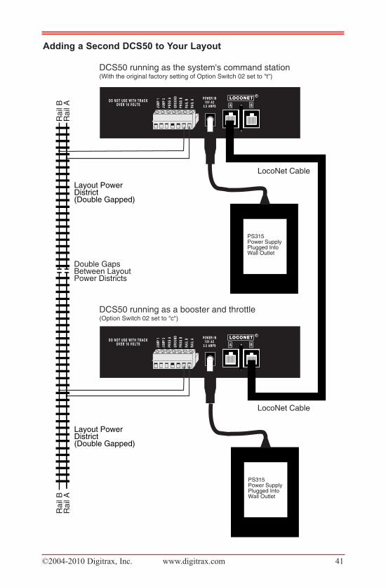
©2004-2010 Digitrax, Inc. www.digitrax.com 41
adding�a�Second�DCS50�to�your�layout
BAJUM
P 1
JUM
P1
GROU
NDGR
OUND
RAIL
BRA
ILB
JUM
P 2
JUM
P2
PROG
APR
OGA
RAIL
ARA
ILA
PROG
BPR
OGB L O C O N E TL O C O N E T
RP O W E R I NP O W E R I N
1 5 V A C1 5 V A C2 . 5 A M P S2 . 5 A M P S
PS315Power SupplyPlugged IntoWall Outlet
Layout Power District (Double Gapped)
D O N O T U S E W I T H T R A C KD O N O T U S E W I T H T R A C KO V E R 1 6 V O L T SO V E R 1 6 V O L T S
Adding A Second DCS50 To Your Layout
DCS50 running as the system's command stationR
ail
AR
ail
B
Double GapsBetween LayoutPower Districts
LocoNet Cable
Ra
il A
Ra
il B
LocoNet Cable
(With the original factory setting of Option Switch 02 set to "t")
DCS50 running as a booster and throttle(Option Switch 02 set to "c")
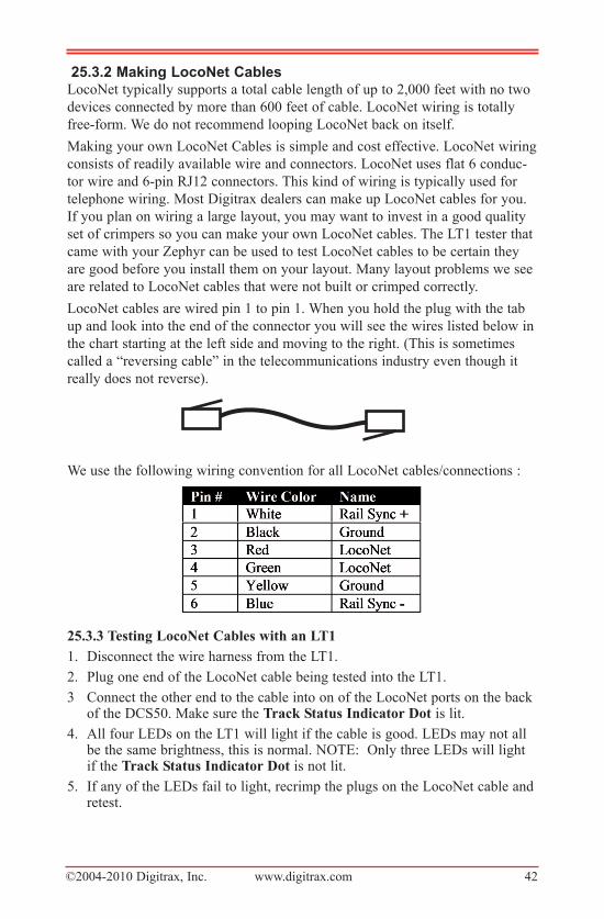
©2004-2010 Digitrax, Inc. www.digitrax.com 42
25.3.2�Making�loconet�CablesLocoNet typically supports a total cable length of up to 2,000 feet with no two
devices connected by more than 600 feet of cable. LocoNet wiring is totally
free-form. We do not recommend looping LocoNet back on itself.
Making your own LocoNet Cables is simple and cost effective. LocoNet wiring
consists of readily available wire and connectors. LocoNet uses flat 6 conduc-
tor wire and 6-pin RJ12 connectors. This kind of wiring is typically used for
telephone wiring. Most Digitrax dealers can make up LocoNet cables for you.
If you plan on wiring a large layout, you may want to invest in a good quality
set of crimpers so you can make your own LocoNet cables. The LT1 tester that
came with your Zephyr can be used to test LocoNet cables to be certain they
are good before you install them on your layout. Many layout problems we see
are related to LocoNet cables that were not built or crimped correctly.
LocoNet cables are wired pin 1 to pin 1. When you hold the plug with the tab
up and look into the end of the connector you will see the wires listed below in
the chart starting at the left side and moving to the right. (This is sometimes
called a “reversing cable” in the telecommunications industry even though it
really does not reverse).
We use the following wiring convention for all LocoNet cables/connections :
25.3.3 Testing LocoNet Cables with an LT1
1. Disconnect the wire harness from the LT1.
2. Plug one end of the LocoNet cable being tested into the LT1.
3 Connect the other end to the cable into on of the LocoNet ports on the backof the DCS50. Make sure the Track Status Indicator Dot is lit.
4. All four LEDs on the LT1 will light if the cable is good. LEDs may not allbe the same brightness, this is normal. NOTE: Only three LEDs will lightif the Track Status Indicator Dot is not lit.
5. If any of the LEDs fail to light, recrimp the plugs on the LocoNet cable andretest.
©2004-2010 Digitrax, Inc. www.digitrax.com 43
26.0 Locomotive Dispatching ProceduresSome users prefer to “dispatch” or release all addresses active in their system
before shutting down. This can prevent unexpected results when you power up
the layout again.
To release/dispatch addresses (this is optional):1. Press the lOCO key.
2. Enter the loco address on the numeric keypad. The display will flash theFunction Indicator Dot and the loco address. Press the lOCO key again.
3. Set the Throttle Knob to StOp.
4. Press the exit key.
5. Repeat for all locos/addresses used in your session.
To clear all addresses and MU information, set Option Switch 36 to “c” 1. Press the prOg key.
2. Press the SwitCh key. The Switch Indicator Dot will blink to indicate youare in Option Switch configuration mode.
3. Enter 036.
4. Press the c/- key
5. Press the exit key.
To Shut Down the System:1. Press the Power Key to turn track power off
2. Unplug the PS315 from the wall.
©2004-2010 Digitrax, Inc. www.digitrax.com 44
27.0 Troubleshooting 27.1��nothing�is�respondingIs track power turned on? If the Track Status Indicator Dot is not lit, press
the pOwer Key to turn on track power.
27.2�no�power�or�intermittent�OperationThe majority of intermittent operation problems can be traced to bad connec-
tions and poor or noisy wheel pickups on locomotives. The DCC digital packet
communication strategy performs exceptionally well in a less than perfect envi-
ronment, and will often mask bad connections until they are really impossible
to work with! Clean the track and wheel pickups of your locomotives.
27.2.1�the�Quarter�trickIf your track does not have adequate power supply to the locomotives, then the
DCC signal won’t get through either. Take a quarter or screwdriver blade and
go around your layout creating electrical shorts by laying the quarter/screw-
driver blade across both rails every 10 feet. Your DCS50 should shutdown
when the short is present. You will see walking “o” s on your display to indicate
a short circuit shutdown. When the short is removed, the booster should return
to normal operation. If the unit does not see a short or it does not return to nor-
mal operation after the short is removed, then you need to add more feeders.
27.2.2�the�lt1�testerCheck your LocoNet cables with the LT1 tester to be sure you don’t have any
cables that were made incorrectly. See Section 25.3.3.
27.3�emergency�Stop
If the layout starts to “get away” on you, press the pOwer Key to stop every-
thing on the layout.
27.4�Mechanical�Drive�train�problemsPay attention to the mechanical drive train and free movement of the locomo-
tive wheel sets. This is especially important with inexpensive locomotives.
Using Digitrax decoders with appropriate programming settings, you can
achieve surprisingly good quality operation, if you carefully adjust the mecha-
nisms for smooth running. See manufacturers instructions.
27.5��“Strange”�locomotive�lightsIf you can’t control the operation of the lights in your locomotive with the
DCS50, be sure that the decoder is programmed to match the speed setting
commands of your DCS50 command station. The factory setting for the DCS50
is advanced 28/128 speed step mode.
Your Digitrax decoder was shipped programmed to 28/128 speed step mode.
You may have changed your decoder’s programming when performing the
decoder test procedure. In any case, if you are not able to turn the locomotives
lights on and off, you will need to change CV 29 to a value of “06” to have
proper light operation when using the DCS50 in its optimum 28/128 speed step
©2004-2010 Digitrax, Inc. www.digitrax.com 45
mode. Refer to Section 16.3 for programming instructions. Additional informa-
tion about programming CV29 is available in your Digitrax Decoder Manual.
If you have a Digitrax Series 3 decoder and you can control the lights but not
the motor, check for a motor short circuit. These decoders are designed to shut-
down motor operation when a short is detected to prevent damage to the
decoder.
27.6�Decoder�won’t�respondDid you select the locomotive’s actual address? If you don’t know the
address of the locomotive on the track, you can read it back in programming
mode or you can reprogram it to a new address. See Section 16.6
Is the loco on powered track?
Make sure the Track Power Indicator on the DCS50 is on, press the pOwer
key to turn on track power. See Section 7.2
Use the “Quarter Trick” to test for track power at several locations around the
layout. If there is not track power, check your layout wiring. See Section 27.2.1
Can you select the loco on your throttle?
Is the loco in use by another throttle did the throttle display “StLo”. If it did,
then dispatch the loco from the other throttle.
If the loco is part of an MU, the MU Indicator Dot will light up when you
select it. you can control the functions, but not speed and direction.
Do the settings in CV29, the configuration register, match the command
station output? If your decoder is a 14 step decoder running on any Digitrax
system using factory settings, status editing will be needed for that decoder.
Have you reset any CVs since the last time you ran the loco?
It is possible to set acceleration so high that it will take 10 minutes for the loco
to start moving. Try resetting the CV values to their factory settings and then
running the locomotive. Remember, Digitrax uses address 03 for the factory
setting for all decoders. Check your decoder manual for factory settings and
instructions on resetting the values.
Was the loco running normally just before it stopped?
Check to make sure the decoder has not heated up and gone into a thermal
shutdown. If it is warm, remove the loco from the track, let it cool off and then
see if it starts again. Also check for localized track problems.
Are there burn marks on the decoder? You’ll need to send it in for repair!
If all else fails, reprogram the decoder address and reset CVs to factory original
values. See your decoder manual for factory settings and reset instructions.
Does your throttle say “FULL” ?
This means that the Zephyr system’s capacity to handle operating locos is full.
The DCS50 can run up to 10 addresses at the same time. This includes all
decoder/locomotive addresses in use on the system, whether they are being run
individually or as part of an MU. If you have the “FULL” message, be sure
that all locos that are not running are released from throttles. If you run into
©2004-2010 Digitrax, Inc. www.digitrax.com 46
this problem often, you should consider a command station with more capacity
such as the DB150 or DCS100. If you want to clear all of the loco addresses
and consist information in the DCS50 and start over, set OpSw 36 to “c”. See
Section 26 for full instructions on dispatching locomotives and clearing the
address register.
27.7�i’m�totally�lost!If your DCS50 display isn’t showing you what you expect based on the manu-
al, press the exit key to return to normal operating mode. Then try the throttle
task again. If you think you might have made an inadvertent change to one of
the factory settings in either the decoder or the command station, try resetting
everything to the factory settings and try the task again. See your decoder
instructions for resetting the factory settings of the decoder. See Section 28 for
resetting the DCS50 factory settings.
27.8�DCS50�ShutdownIf the DCS50 shuts down briefly and then comes back on again, it is probably
being run too close to its pre-set current limit of 2.5 Amps. In this case it may
clip or mutilate some outgoing packets of information to keep the track current
within acceptable limits. To solve this problem, reduce the track current load
by running fewer locomotives or setting up additional power districts and
adding more boosters to provide more power for the layout. See Section 25.3.
28.0 DCS50 Option Switch SetupThe DCS50 has several system operation options that you can use to customize
your operations. The DCS50 is set up at the factory to run right "out of the
box." Most customers never have any need to change these options.
Changing DCS50 Option Switches1. See the DCS50 Option Switch Table that follows to decide which option
switches you want to change.
2. Press the prOg key. The display shows the last decoder programmingmode used by the DCS50.
3. Press the SwitCh key. The display shows the last switch used by theDCS50 and its commanded position.
4. Use the numeric keypad to enter the number of the Option Switch you wantto change.
5. Press the c/-�or t/+ key to set the OpSw to the setting desired.
6. Press exit when finished. The DCS50 display will show -cS- to indicatethat you are running in command station mode or -br- to indicate that youare running as a booster/throttle only.
The following table shows the effects of setting various option switches. The
factory settings for all DCS50 option switches are noted in the right column.
To reset the DCS50 Option Switches to factory settings:
If you change option switches and experience unexpected results, just set
OpSw 39 to “c” (closed) to reset the unit to the original factory settings.
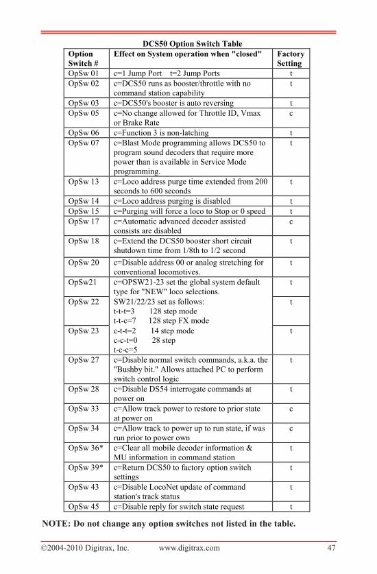
©2004-2010 Digitrax, Inc. www.digitrax.com 47
NOTE: Do not change any option switches not listed in the table.
DCS50 Option Switch Table Option Switch #
Effect on System operation when "closed" Factory Setting
OpSw 01 c=1 Jump Port t=2 Jump Ports t OpSw 02 c=DCS50 runs as booster/throttle with no
command station capability t
OpSw 03 c=DCS50's booster is auto reversing t OpSw 05 c=No change allowed for Throttle ID, Vmax
or Brake Rate c
OpSw 06 c=Function 3 is non-latching t OpSw 07 c=Blast Mode programming allows DCS50 to
program sound decoders that require more power than is available in Service Mode programming.
t
OpSw 13 c=Loco address purge time extended from 200 seconds to 600 seconds
t
OpSw 14 c=Loco address purging is disabled t OpSw 15 c=Purging will force a loco to Stop or 0 speed t OpSw 17 c=Automatic advanced decoder assisted
consists are disabled c
OpSw 18 c=Extend the DCS50 booster short circuit shutdown time from 1/8th to 1/2 second
t
OpSw 20 c=Disable address 00 or analog stretching for conventional locomotives.
t
OpSw21 c=OPSW21-23 set the global system default type for "NEW" loco selections.
t
OpSw 22 SW21/22/23 set as follows: t-t-t=3 128 step mode t-t-c=7 128 step FX mode
t
OpSw 23 c-t-t=2 14 step mode c-c-t=0 28 step t-c-c=5
t
OpSw 27 c=Disable normal switch commands, a.k.a. the "Bushby bit." Allows attached PC to perform switch control logic
t
OpSw 28 c=Disable DS54 interrogate commands at power on
t
OpSw 33 c=Allow track power to restore to prior state at power on
c
OpSw 34 c=Allow track to power up to run state, if was run prior to power own
c
OpSw 36* c=Clear all mobile decoder information & MU information in command station
t
OpSw 39* c=Return DCS50 to factory option switch settings
t
OpSw 43 c=Disable LocoNet update of command station's track status
t
OpSw 45 c=Disable reply for switch state request t

©2004-2010 Digitrax, Inc. www.digitrax.com 48
29.0 LocoNet: The Digitrax Difference!29.1��System�architectureSystem architecture is the biggest difference among DCC sys-
tems. System architecture is the way the components of a DCC
system communicate among themselves. Digitrax LocoNet is a
Peer to Peer local area network (LAN) designed specifically for
model railroad operation. LocoNet wiring is cost effective,
flexible and expandable to accommodate almost anything you want to do with
your railroad today and in the future.
29.2�System�expansionThe following diagram shows some of the expansion possibilities available
with LocoNet. LocoNet sets Zephyr apart from other entry level DCC sets
because it’s expandable. With Digitrax LocoNet your DCC journey starts at the
Main Station with your first “starter” set. From there, it’s up to you. You can
add:
Mobile decoders for your locomotives
Function decoders for more lights and other functions on your locos.
More boosters to give you more power to let you run more trains,
More throttles for more operators,
Different types of throttles,
More throttle jacks for convenient walk around operation,
Infrared or radio capability for more freedom for operators,
Accessory decoders for turnout and accessory control,
Detection,
Transponding,
Signaling,
A personal computer to automate operations or for dispatching,
Use your PDA as a throttle,
Automatic reversing with a booster or power manager,
And the list goes on and on.
With LocoNet, you customize your layout to run the way you want it to run!
There is a lot of information available to help you along the way. The Digitrax
Big Book of DCC shows you how to implement DCC on your layout by using
examples of actual layouts and showing you how they work. The Digitrax web
site, www.digitrax.com, contains a wealth of information on all of our prod-
ucts. Digitrax users maintain a chat list that can be very helpful, too.
LLooccooNNeett
R
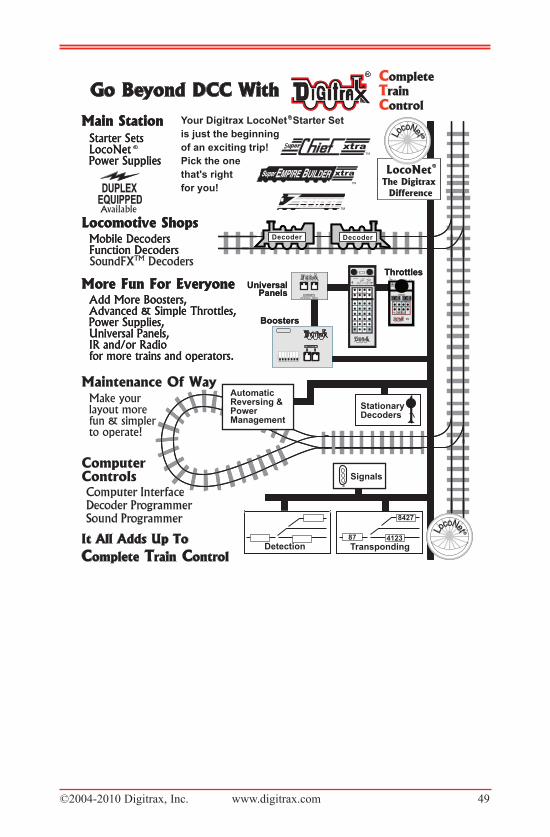
©2004-2010 Digitrax, Inc. www.digitrax.com 49
Available
Computer InterfaceComputer InterfaceDecoder ProgrammerDecoder ProgrammerSound ProgrammerSound Programmer
TM
EEMPIREMPIRE B BUILDERUILDERSuperSuper
00 00 00 00
©2004-2010 Digitrax, Inc. www.digitrax.com 50
30.0 FCC InformationRadio or TV Interference: (this information is MANDATED by the FCC)
This equipment has been tested and found to comply with the limits for a ClassB digital device, pursuant to part 15 of the FCC rules. These limits aredesigned to provide reasonable protection against harmful interference in a res-idential environment. This equipment generates, uses and can radiate radio fre-quency energy and, if not installed and used in accordance with the instructionmanual, may cause harmful interference to radio communications. However,there is no guarantee that interference will not occur in a particular installation.If this equipment does cause harmful interference to radio or television recep-tion, which can be determined by turning the equipment off and on, the user isencouraged to try to correct the interference by one or more of the followingmeasures:
• Reorient or relocate the receiving antenna.• Increase the separation between the equipment and the receiver.• Connect the equipment into an outlet on a circuit different form that to
which the receiver is connected.• Consult the dealer or an experienced radio/TV technician for help.
Note that any modifications to the equipment not expressly approved byDigitrax voids the user’s authority to operate under and be in compliance withCFR 47 rules, as administered by the Federal Communication Commission.Digitrax believes any conscientiously installed equipment following guidelinesin this manual would be unlikely to experience RFI problems.
For Canadian Users:
“This digital apparatus does not exceed the Class B limits for Radio noiseemission from digital apparatus set out in the Radio Interference Regulation orthe Canadian Department of Communications.”
Le present appariel numerique n emet pas de bruits radio-electriques depassantles limites applicables aux appareils numeriques de la classe B prescrites dansle Reglement sur le brouillage radioelectrique edicte par le ministere desCommunications du Canada.
©2004-2010 Digitrax, Inc. www.digitrax.com 51
31.0 Digitrax ‘No Worries’ Warranty & RepairDigitrax gives a one year “No Worries" Warranty against manufacturing defects
and accidental customer damage on all Digitrax products. That's it! A simple,
straightforward warranty with no tricky language! For complete warranty and
repair details see www.digitrax.com. Please contact Digitrax tech support at
(850) 872 9890 before sending anything to us for service so that we can try and
resolve the problem by phone or e-mail. Except as expressly stated in the full
warranty statement, there are no warranties, express or implied, including but
not limited to any warranties of merchantability or fitness for a
particular purpose. .
Decoders- Digitrax carefully tests every decoder we ship to be sure that you
receive reliable products. Because we want you to be comfortable installing
your own decoders, we outline a decoder test procedure that you can perform
so that you can be sure your decoder works before you begin installing it in
your locomotive.
Do not remove the shrink-wrap protective sleeves from Digitrax decoders or
open the Command Stations or other products. None of the units have user
serviceable parts, and opening them will void ALL warranty protection.
Please don’t return anything to Digitrax without calling and getting return
instructions.
Please call tech support at (850) 872 9890 before you send anything to us for
service so that we can try and resolve the problem by phone if possible.
All warranties on Digitrax products are limited to refund of purchase price or
repair or replacement of Digitrax products at the sole discretion of Digitrax. In
the event that Digitrax products are not installed or used in accordance with the
manufacturer’s specifications, any and all warranties either expressed or
implied are void. Except to the extent expressly stated in this section, there are
no warranties, express or implied, including but not limited to any warranties
of merchantability or fitness for a particular purpose.
Digitrax, Inc. reserves the right to make changes in design and specifications,
and/or to make additions or improvements in its products without imposing any
obligations upon itself to install these changes, additions or improvements on
products previously manufactured.
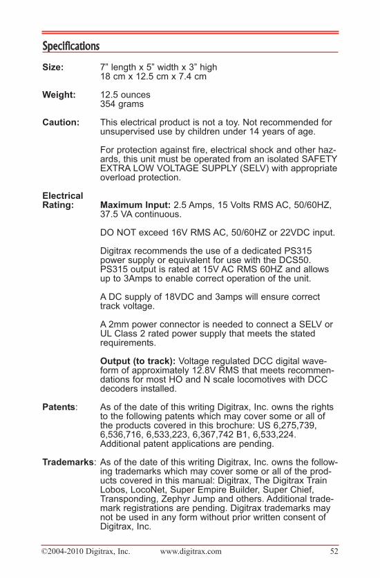
©2004-2010 Digitrax, Inc. www.digitrax.com 52
Specifications
Size: 7” length x 5” width x 3” high18 cm x 12.5 cm x 7.4 cm
weight: 12.5 ounces354 grams
Caution: This electrical product is not a toy. Not recommended forunsupervised use by children under 14 years of age.
For protection against fire, electrical shock and other haz-ards, this unit must be operated from an isolated SAFETYEXTRA LOW VOLTAGE SUPPLY (SELV) with appropriateoverload protection.
electrical�rating: Maximum�input: 2.5 Amps, 15 Volts RMS AC, 50/60HZ,
37.5 VA continuous.
DO NOT exceed 16V RMS AC, 50/60HZ or 22VDC input.
Digitrax recommends the use of a dedicated PS315power supply or equivalent for use with the DCS50.PS315 output is rated at 15V AC RMS 60HZ and allowsup to 3Amps to enable correct operation of the unit.
A DC supply of 18VDC and 3amps will ensure correcttrack voltage.
A 2mm power connector is needed to connect a SELV orUL Class 2 rated power supply that meets the statedrequirements.
Output�(to�track): Voltage regulated DCC digital wave-form of approximately 12.8V RMS that meets recommen-dations for most HO and N scale locomotives with DCCdecoders installed.
patents: As of the date of this writing Digitrax, Inc. owns the rightsto the following patents which may cover some or all ofthe products covered in this brochure: US 6,275,739,6,536,716, 6,533,223, 6,367,742 B1, 6,533,224.Additional patent applications are pending.
trademarks: As of the date of this writing Digitrax, Inc. owns the follow-ing trademarks which may cover some or all of the prod-ucts covered in this manual: Digitrax, The Digitrax TrainLobos, LocoNet, Super Empire Builder, Super Chief,Transponding, Zephyr Jump and others. Additional trade-mark registrations are pending. Digitrax trademarks maynot be used in any form without prior written consent ofDigitrax, Inc.

©2004-2010 Digitrax, Inc. www.digitrax.com 53
Copyrights Copyright © Digitrax, Inc. world wide rights reserved. Contents of these pages are
not to be reproduced or reprinted in any form without theexpress written consent of Digitrax, Inc.
Digitrax, Inc. is not responsible for unintentional
errors or omissions in this document.
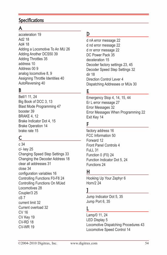
©2004-2010 Digitrax, Inc. www.digitrax.com 54
Aacceleration 19
Ad2 18
Ad4 18
Adding a Locomotive To An MU 26
Adding Another DCS50 39
Adding Throttles 35
address 10
Address 00 9
analog locomotive 8, 9
Assigning Throttle Identities 40
AutoReversing 40
BBell/1 11, 24
Big Book of DCC 3, 13
Blast Mode Programming 47
booster 39
BRAKE 4, 12
Brake Indicator Dot 4, 15
Brake Operation 14
brake rate 15
Cc 34
c/- key 25
Changing Speed Step Settings 33
Changing the Decoder Address 18
clear all addresses 31
close 34
configuration variables 16
Controlling Functions F0-F8 24
Controlling Functions On MUed
Locomotives 28
Coupler/3 25
cS 7
current limit 32
Current overload 32
CV 16
CV Key 19
CV-RD 18
CV-WR 19
Dd nA error message 22
d nd error message 22
d nr error message 22
DC Power Pack 35
deceleration 15
Decoder factory settings 23, 45
Decoder Speed Step Settings 32
dir 18
Direction Control Lever 4
Dispatching Addresses or MUs 30
EEmergency Stop 4, 14, 15, 44
Er L error message 27
Error Messages 32
Error Messages When Programming 22
Exit Key 14
Ffactory address 16
FCC Information 50
Forward 12
Front Panel Controls 4
FuLL 31
Function 0 (F0) 24
Function Indicator Dot 5, 24
Functions 24
HHooking Up Your Zephyr 6
Horn/2 24
JJump Indicator Dot 5, 35
Jump Port 6, 35
LLamp/0 11, 24
LED Display 5
Locomotive Dispatching Procedures 43
Locomotive Speed Control 14
Specifications
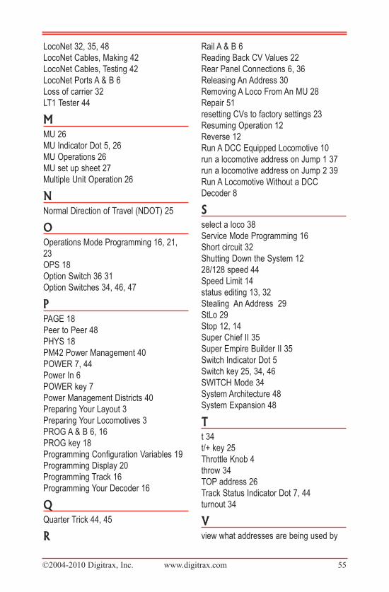
©2004-2010 Digitrax, Inc. www.digitrax.com 55
LocoNet 32, 35, 48
LocoNet Cables, Making 42
LocoNet Cables, Testing 42
LocoNet Ports A & B 6
Loss of carrier 32
LT1 Tester 44
MMU 26
MU Indicator Dot 5, 26
MU Operations 26
MU set up sheet 27
Multiple Unit Operation 26
NNormal Direction of Travel (NDOT) 25
OOperations Mode Programming 16, 21,
23
OPS 18
Option Switch 36 31
Option Switches 34, 46, 47
PPAGE 18
Peer to Peer 48
PHYS 18
PM42 Power Management 40
POWER 7, 44
Power In 6
POWER key 7
Power Management Districts 40
Preparing Your Layout 3
Preparing Your Locomotives 3
PROG A & B 6, 16
PROG key 18
Programming Configuration Variables 19
Programming Display 20
Programming Track 16
Programming Your Decoder 16
QQuarter Trick 44, 45
R
Rail A & B 6
Reading Back CV Values 22
Rear Panel Connections 6, 36
Releasing An Address 30
Removing A Loco From An MU 28
Repair 51
resetting CVs to factory settings 23
Resuming Operation 12
Reverse 12
Run A DCC Equipped Locomotive 10
run a locomotive address on Jump 1 37
run a locomotive address on Jump 2 39
Run A Locomotive Without a DCC
Decoder 8
Sselect a loco 38
Service Mode Programming 16
Short circuit 32
Shutting Down the System 12
28/128 speed 44
Speed Limit 14
status editing 13, 32
Stealing An Address 29
StLo 29
Stop 12, 14
Super Chief II 35
Super Empire Builder II 35
Switch Indicator Dot 5
Switch key 25, 34, 46
SWITCH Mode 34
System Architecture 48
System Expansion 48
Tt 34
t/+ key 25
Throttle Knob 4
throw 34
TOP address 26
Track Status Indicator Dot 7, 44
turnout 34
Vview what addresses are being used by
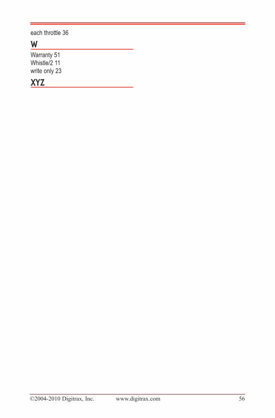
©2004-2010 Digitrax, Inc. www.digitrax.com 56
each throttle 36
WWarranty 51
Whistle/2 11
write only 23
XYZ

©2004-2010 Digitrax, Inc. www.digitrax.com 57
Notes

©2004-2010 Digitrax, Inc. www.digitrax.com 58
Notes
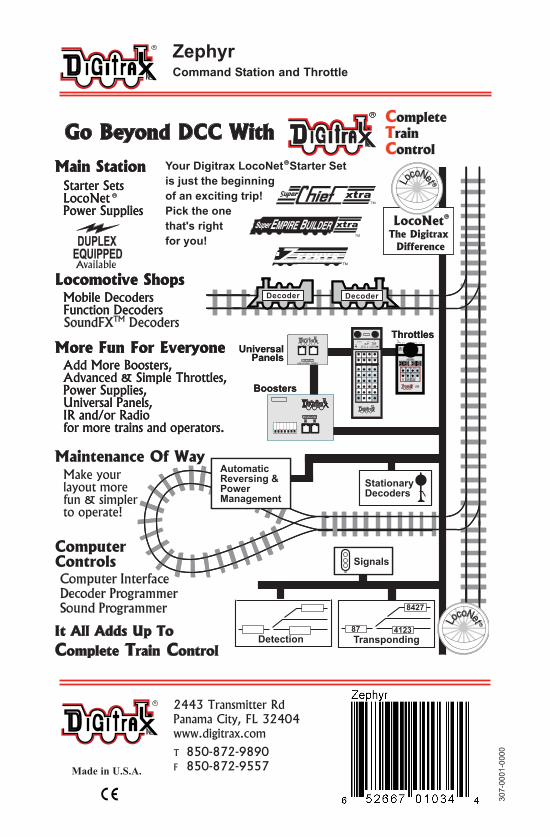
Made in U.S.A.
Available
Computer InterfaceComputer InterfaceDecoder ProgrammerDecoder ProgrammerSound ProgrammerSound Programmer
TM
EEMPIREMPIRE B BUILDERUILDERSuperSuper
00 00 00 00
30
7-0
00
1-0
00
0
ZephyrCommand�Station�and�throttle�
2443 Transmitter RdPanama City, FL 32404www.digitrax.com
T 850-872-9890F 850-872-9557