Zener effect and Zener diode –When a Zener diode is reverse-biased, it acts at the breakdown...
24
• Zener effect and Zener diode – When a Zener diode is reverse- biased, it acts at the breakdown region, when it is forward biased, it acts like a normal PN junction diode • Avalanche Effect – Gain kinetic energy – hit another atom –produce electron and hole pair Recall-Lecture 6
-
Upload
keegan-sweatman -
Category
Documents
-
view
239 -
download
2
Transcript of Zener effect and Zener diode –When a Zener diode is reverse-biased, it acts at the breakdown...

• Zener effect and Zener diode– When a Zener diode is reverse-biased, it acts
at the breakdown region, when it is forward biased, it acts like a normal PN junction diode
• Avalanche Effect– Gain kinetic energy – hit another atom –
produce electron and hole pair
Recall-Lecture 6

• Voltage Regulator using Zener Diode
1. The zener diode holds the voltage constant regardless of the current
2. The load resistor sees a constant voltage regardless of the current
The remainder of VPS drops
across Ri

RectifierRectifier

Rectifier Circuits
A dc power supply is required to bias all electronic circuits.
A diode rectifier forms the first stage of a dc power supply.
Diagram of an Electronic Power Supply
Rectification is the process of converting an alternating (ac) voltage into one that is limited to one polarity.
Rectification is classified as half-wave or full-wave rectifier.
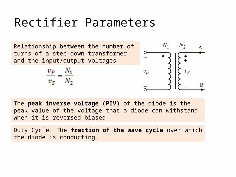
Rectifier Parameters
Relationship between the number of turns of a step-down transformer and the input/output voltages
The peak inverse voltage (PIV) of the diode is the peak value of the voltage that a diode can withstand when it is reversed biased
Duty Cycle: The fraction of the wave cycle over which the diode is conducting.

i
vDV
V
Equation of VO and current when diode is conducting
• Vs < V, diode off, open circuit, no current flow, Vo = 0V
• Vs > V, diode conducts, current flows, Vo = Vs – V
Vp

• Vs< V, diode off, open circuit, no current flow,Vo = 0V
• Vs> V, diode conducts,current flows and Vo = Vs – V
Vs = Vpsin t
Notice that the peak voltage of Vo is lower
Vs >V
V
Vp

SEM III 2013/2014• Consider the rectifier circuit in the figure below. Let R = 1 k, and the diode
has the properties of V = 0.6 V and rf = 20 . Assume vI = 10 sin t (V)
i. Determine the peak value of the diode currentii. Sketch vO versus time, t. Label the peak value of vO.

Solution

FULL WAVE RECTIFIER
• Center-Tapped• Bridge

Positive cycle, D2 off, D1 conducts;
Vo – Vs + V = 0
Vo = Vs - V
Full-Wave Rectification – circuit with center-tapped transformer
Since a rectified output voltage occurs during both positive and negative cycles of the input signal, this circuit is called a full-wave rectifier.
Also notice that the polarity of the output voltage for both cycles is the same
Negative cycle, D1 off, D2 conducts;
Vo – Vs + V = 0
Vo = Vs - V

Vs = Vpsin t
V
-V
Notice again that the peak voltage of Vo is lower since Vo = Vs - V
Vp
• Vs < V, diode off, open circuit, no current flow,Vo = 0V

Positive cycle, D1 and D2 conducts, D3 and D4 off;
+ V + Vo + V – Vs = 0 Vo = Vs - 2V
Full-Wave Rectification –Bridge Rectifier
Negative cycle, D3 and D4 conducts, D1 and D2 off + V + Vo + V – Vs = 0 Vo = Vs - 2V
Also notice that the polarity of the output voltage for both cycles is the same

• A full-wave center-tapped rectifier circuit is shown in Fig. 3.1. Assume that for each diode, the cut-in voltage, V = 0.6V and the diode forward resistance, rf is 15. The load resistor, R = 95 . Determine:
i. peak output voltage, Vo across the load, R
ii. Sketch the output voltage, Vo and label its peak value.
25: 1
125 V (peak voltage)
( sine wave )

• SOLUTIONi. peak output voltage, Vo
Vs (peak) = 125 / 25 = 5V
V +ID(15) + ID (95) - Vs(peak) = 0 ID = (5 – 0.6) / 110 = 0.04 A Vo (peak) = 95 x 0.04 = 3.8V
ii.
3.8V
Vo
t
Duty Cycle: The fraction of the wave cycle over which the diode is conducting.

EXAMPLE 3.1 – Half Wave RectifierDetermine the currents and voltages of the half-wave rectifier circuit. Consider the half-wave rectifier circuit shown in Figure. Assume and . Also assume that Determine the peak diode current, maximum reverse-bias diode voltage, the fraction of the wave cycle over which the diode is conducting.
A simple half-wave battery charger circuit
-VR + VB + 18.6 = 0VR = 24.6 V
- VR +
+
-

6VThis node must be at least 6.6V
The peak inverse voltage (PIV) of the diode is the peak value of the voltage that a diode can withstand when it is reversed biased

Type of Rectifier
PIV
Half Wave Peak value of the input secondary voltage, Vs (peak)
Full Wave : Center-Tapped
2Vs(peak) - V
Full Wave: Bridge
Vs(peak)- V

Example: Half Wave Rectifier
Given a half wave rectifier with input primary voltage, Vp = 80 sin t and the transformer turns ratio, N1/N2 = 6. If the diode is ideal diode, (V = 0V), determine the value of the peak inverse voltage.
1. Get the input of the secondary voltage:
80 / 6 = 13.33 V
1. PIV for half-wave = Peak value of the input voltage = 13.33 V

EXAMPLE 3.2 Calculate the transformer turns ratio and the PIV voltages for each type of the full wave rectifiera)center-tappedb)bridge
Assume the input voltage of the transformer is 220 V (rms), 50 Hz from ac main line source. The desired peak output voltage is 9 volt; also assume diodes cut-in voltage = 0.6 V.
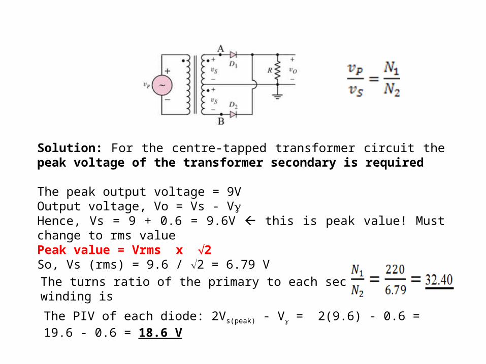
Solution: For the centre-tapped transformer circuit the peak voltage of the transformer secondary is required
The peak output voltage = 9VOutput voltage, Vo = Vs - VHence, Vs = 9 + 0.6 = 9.6V this is peak value! Must change to rms valuePeak value = Vrms x 2 So, Vs (rms) = 9.6 / 2 = 6.79 V
The turns ratio of the primary to each secondary winding is
The PIV of each diode: 2Vs(peak) - V = 2(9.6) - 0.6 = 19.6 - 0.6 = 18.6 V
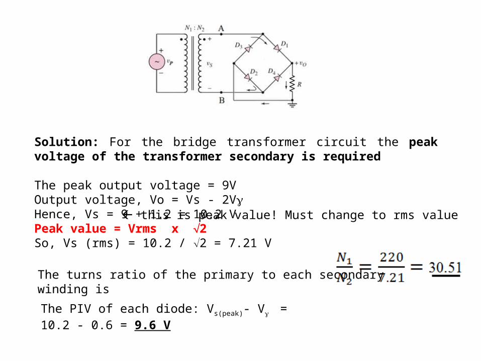
Solution: For the bridge transformer circuit the peak voltage of the transformer secondary is required
The peak output voltage = 9VOutput voltage, Vo = Vs - 2VHence, Vs = 9 + 1.2 = 10.2 VPeak value = Vrms x 2 So, Vs (rms) = 10.2 / 2 = 7.21 V
The turns ratio of the primary to each secondary winding is
The PIV of each diode: Vs(peak)- V = 10.2 - 0.6 = 9.6 V
this is peak value! Must change to rms value