Zelio soft
45
1 Zelio logic tutorial 1 The Products Congratulations! You have chosen one of the following Zelio products: 2 Environment Zelio Logic is programmable using the Zelio Soft program or in Direct Entry Mode (Ladder language). Zelio Soft allows you to program your software in FBD language or in Ladder language. You must be connected to your PC in order to use the software program. Use an SR2CBL01 cord to connect to your PC's serial port.
-
Upload
rodrigo-eduardo-feitosa -
Category
Education
-
view
123 -
download
4
Transcript of Zelio soft

1
Zelio logic tutorial1 The ProductsCongratulations! You have chosen one of the following Zelio products:
2 EnvironmentZelio Logic is programmable using the Zelio Soft program or in Direct Entry Mode (Ladderlanguage). Zelio Soft allows you to program your software in FBD language or in Ladderlanguage. You must be connected to your PC in order to use the software program.
Use an SR2CBL01 cord to connect to your PC's serial port.
2
3 Introduction to Zelio Soft3.1 STARTING THE PROGRAM
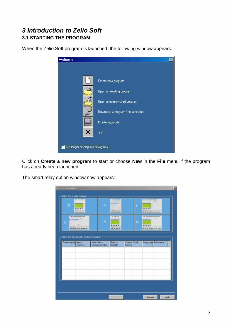
When the Zelio Soft program is launched, the following window appears:
Click on Create a new program to start or choose New in the File menu if the programhas already been launched.
The smart relay option window now appears:
(1) (2) (3)
(5)(4) (6)

3
In this example, we will choose the SR2 B121 BD module:
Click on the category (1) 10/12_I/O_WITHOUT_EXTENSION
The selected category is highlighted in yellow and followed by the list of correspondingmodules:
Click on the corresponding line to select the SR2 B121 BD module:

4
Then click on Next.The program type option screen now appears:
Ladder language is selected by default (yellow outline), click on Next to program inLadder. Click on the FBD icon then on Next to program in FBD.Refer to 3.2 (Ladder language) or 3.3 (FBD) for an example.
3.2 EXEMPLE IN LADDER LANGUAGE3.2.1 Program Editing:
We are going to use the following example:
I1—————Q1
Input I1 is connected to output Q1, which will be in active status (coil in contact mode).
To reproduce this example in the wiring sheet:- Move the mouse arrow over the Discreet Input icon in the lower left corner:

5
A chart with the different contact possibilities (I1 à IE) appears.
Select contact I1 in the chart by clicking and dragging the contact to the first cell in theupper left corner of the wiring sheet. Release the mouse button: Contact I1 is now
- Now move the mouse arrow over the Discreet Output icon at the bottom ofthe screen:A chart with the different contact or coil possibilities appears.
- Select the coil [ in the first line of the chart by clicking and dragging the appropriate coilto the first line of the coil column in the wiring sheet. Release the mouse button: Coil[Q1 is now in place.
Wire the contact to the coil by clicking on the corresponding dotted lines.

6
3.2.2 Program simulation
Simulate the program chosen by clicking on the simulation icon in the upper right corner:
The chosen program is now compiled and the simulation screen appears.Next click on the RUN icon to simulate the module start-up:
A contact or a coil appears in blue if inactive (0) and in red if active (1).Click left to force inputClick on the I1 contact to activate. The Q1 coil is now activated. When you click a secondtime on I1 to disactivate, Q1 is also disactivated.
3.2.3 Program transfer
Power on the module and connect it to the computer before transferring the program:
- Click on the corresponding icon to return to Edit mode:
- In the Transfer menu, select Transfer Program then click on PC>MODULE.
7
Note 1: You cannot write in the module when it is running. Click on STOP Module in theTransfer menu to stop the module.Note 2: If the module connected to the computer is not the module selected when startingthe program, you may select another module by clicking on Module/programming optionin the Module menu.Note 3: When you have loaded a program in FBD in the preceding module (or when youfirst use it), the program should update the module firmware. You will be offered the optionto update during transfer.
After confirmation, the program is transferred to the module.
You can then test the program that is in the module by starting it up (in the application:Click on RUN Module in the Transfer menu).
As in the simulation, if the Zelio Logic I1 input is active, Q1 will be active, and if the I1 isinactive, so is Q1.
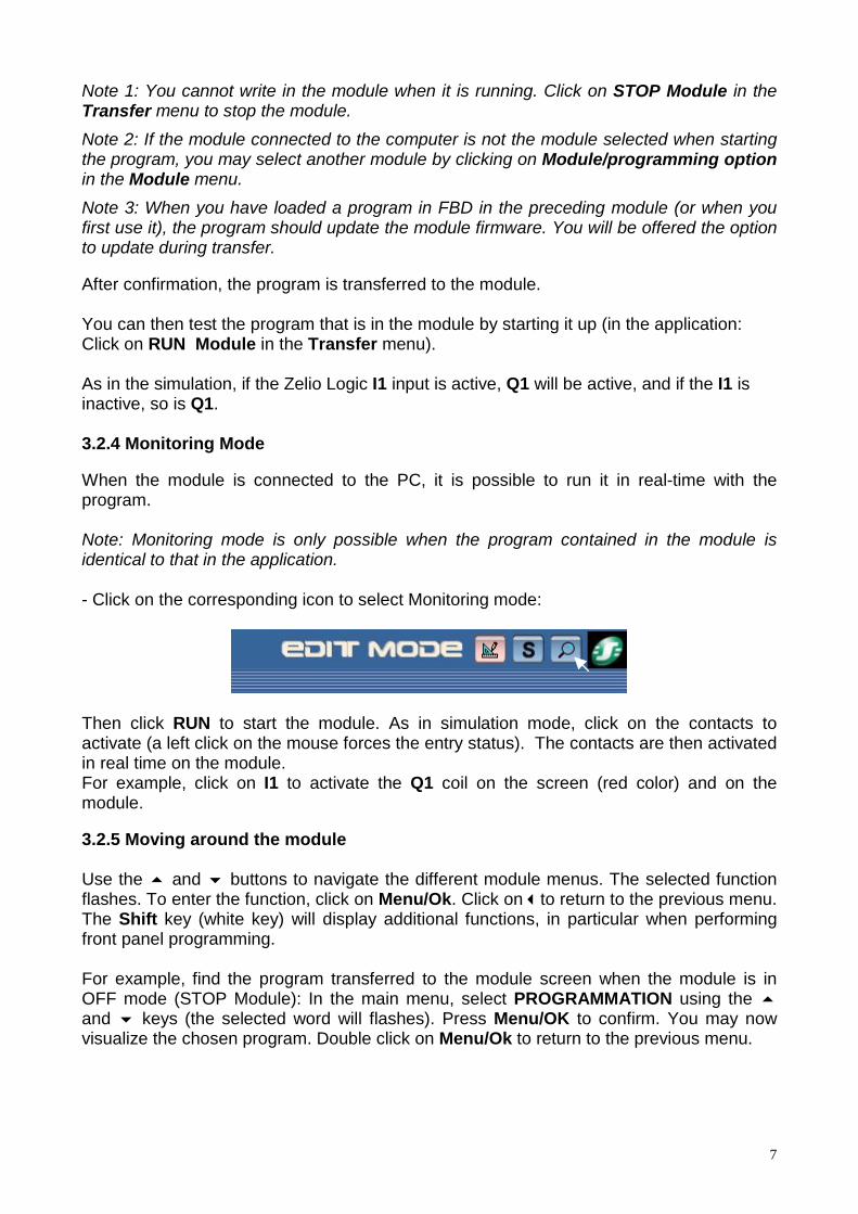
3.2.4 Monitoring Mode
When the module is connected to the PC, it is possible to run it in real-time with theprogram.
Note: Monitoring mode is only possible when the program contained in the module isidentical to that in the application.
- Click on the corresponding icon to select Monitoring mode:
Then click RUN to start the module. As in simulation mode, click on the contacts toactivate (a left click on the mouse forces the entry status). The contacts are then activatedin real time on the module.For example, click on I1 to activate the Q1 coil on the screen (red color) and on themodule.
3.2.5 Moving around the module
Use the ! and " buttons to navigate the different module menus. The selected functionflashes. To enter the function, click on Menu/Ok. Click on#to return to the previous menu.The Shift key (white key) will display additional functions, in particular when performingfront panel programming.
For example, find the program transferred to the module screen when the module is inOFF mode (STOP Module): In the main menu, select PROGRAMMATION using the !and " keys (the selected word will flashes). Press Menu/OK to confirm. You may nowvisualize the chosen program. Double click on Menu/Ok to return to the previous menu.
8
3.3 EXEMPLE IN FBD3.3.1 Program EditingIf you performed the previous example in Ladder language (3.2), select New in the Filemenu to start a program in FBD.
We are going to use the following example:
I1—————Q1
Input I1 is connected to discrete output (TOR) Q1 (Relay).
To reproduce this example in the wiring sheet:
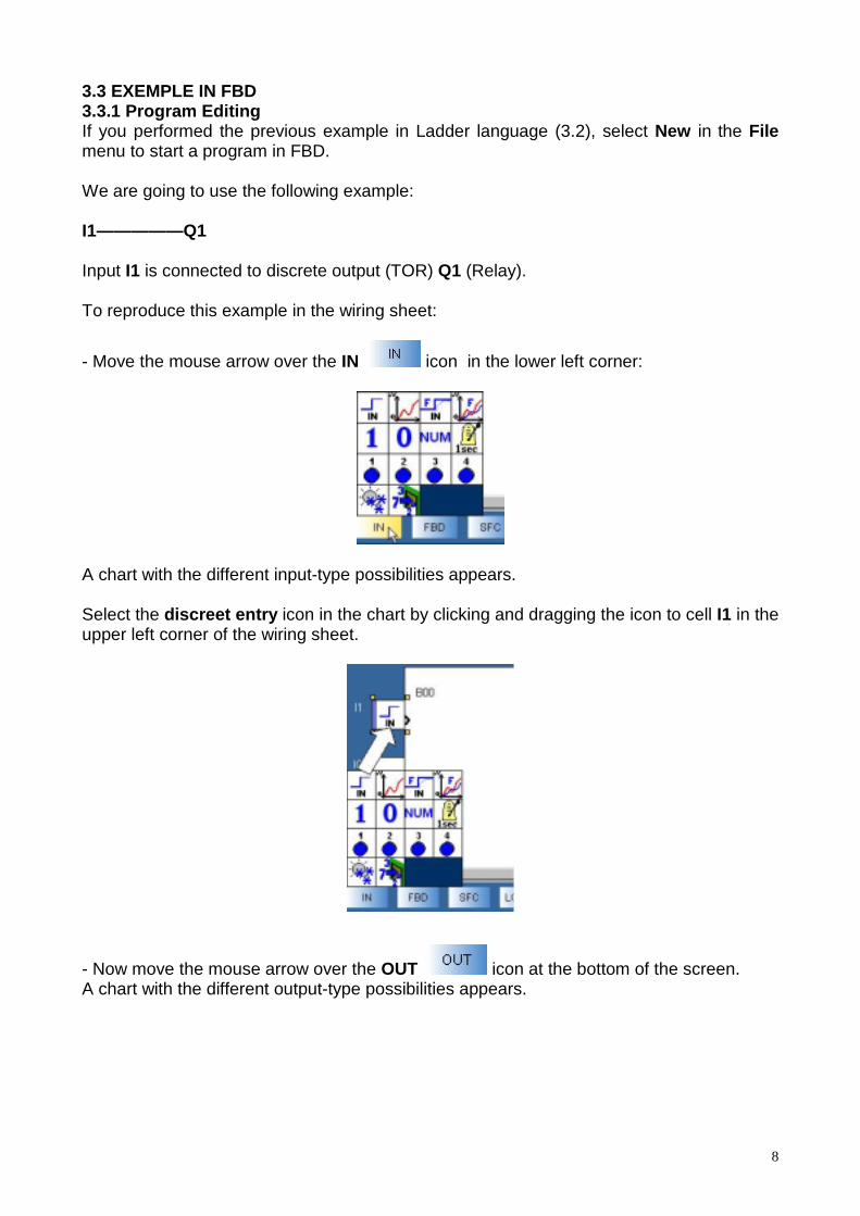
- Move the mouse arrow over the IN icon in the lower left corner:
A chart with the different input-type possibilities appears.
Select the discreet entry icon in the chart by clicking and dragging the icon to cell I1 in theupper left corner of the wiring sheet.
- Now move the mouse arrow over the OUT icon at the bottom of the screen.A chart with the different output-type possibilities appears.
9
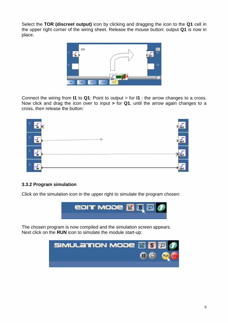
Select the TOR (discreet output) icon by clicking and dragging the icon to the Q1 cell inthe upper right corner of the wiring sheet. Release the mouse button: output Q1 is now inplace.
Connect the wiring from I1 to Q1: Point to output > for I1 : the arrow changes to a cross.Now click and drag the icon over to input > for Q1, until the arrow again changes to across, then release the button:
3.3.2 Program simulation
Click on the simulation icon in the upper right to simulate the program chosen:
The chosen program is now compiled and the simulation screen appears.Next click on the RUN icon to simulate the module start-up:
10
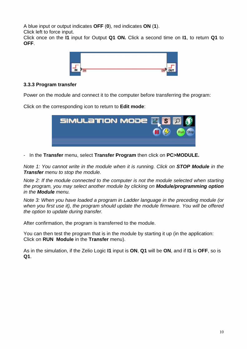
A blue input or output indicates OFF (0), red indicates ON (1).Click left to force input.Click once on the I1 input for Output Q1 ON. Click a second time on I1, to return Q1 toOFF.
3.3.3 Program transfer
Power on the module and connect it to the computer before transferring the program:
Click on the corresponding icon to return to Edit mode:
- In the Transfer menu, select Transfer Program then click on PC>MODULE.
Note 1: You cannot write in the module when it is running. Click on STOP Module in theTransfer menu to stop the module.Note 2: If the module connected to the computer is not the module selected when startingthe program, you may select another module by clicking on Module/programming optionin the Module menu.Note 3: When you have loaded a program in Ladder language in the preceding module (orwhen you first use it), the program should update the module firmware. You will be offeredthe option to update during transfer.
After confirmation, the program is transferred to the module.
You can then test the program that is in the module by starting it up (in the application:Click on RUN Module in the Transfer menu).
As in the simulation, if the Zelio Logic I1 input is ON, Q1 will be ON, and if I1 is OFF, so isQ1.

11
3.3.4 Monitoring Mode
When the module is connected to the PC, it is possible to run it in real-time with theprogram.
Note: Monitoring mode is only possible when the program contained in the module isidentical to that in the application.
Click on the corresponding icon to select Monitoring mode:
Then start the module by clicking on RUN. Just as in simulation, you may activate theinputs by clicking on them, they are then activated in real time on the module.The forcing of input may be made by a left click of the mouse. For example, if you click onI1, the Q1 output will be ON on the screen (red color) and on the module.
3.3.5 Moving around the module
You may move around the different module menus by using the ! and " buttons. Theselected function flashes. To enter the function, click on Menu/Ok. Click on#to return tothe previous menu. The Shift key (white key) will show additional functions.For example, to change the module language: from the main menu, go to LANGUAGEusing the ! and " (the selected word will blink). Press Menu/OK to confirm. Select alanguage by using the ! and " keys then confirm by clicking on Menu/Ok, you may thengo back to the main menu which is translated into the language you have chosen.

12
4 Using Zelio SoftNote: The following descriptions are illustrated with functional examples.
Click on the icon to access the descriptions.If Zelio Soft 2 software is installed, a click on the link will open the program. You may thenselect simulation mode (1) and start the module (RUN) (2).
(1)
(2)
4.1 STARTING A PROGRAMWhen the Zelio Soft program is launched, the following start-up window appears:
Click on Create a new program to start a program, or choose New in the File menu if theprogram has already been launched.

13
The smart relay option window now appears:
(1) (2) (3)
(5)(4) (6)
First select the desired module category :(1) 10/12_I/O_WITHOUT_EXTENSION(2) 10/12_I/O_WITHOUT_SCREEN_WITHOUT_EXTENSION(3) 20_I/O_WITHOUT_EXTENSION(4) 20_I/O_WITHOUT_SCREEN_WITHOUT_EXTENSION(5) 10_I/O_WITH_EXTENSIONS(6) 26_I/O_WITH_EXTENSIONS
Once you have selected the category (the category selected will appear in yellow), thecorresponding module list appears below, click on the module type desired and click onNext or double-click directly on the module.

14
If you have chosen a module with extensions (line SR3), the following screen will appear(if you have chosen a non-extendable model, the programming type option screen willappear directly):
(1)
(3)
(2)
(4)
A summary of the charcacteristics of the module then appears in the upper left corner ofthe window (1). You may go back to the module choice by clicking on Previous.You may then add input/output extensions and/or a communication extension, available toyou in list (2). Just double click on the extension desired, and the total number ofinput/outputs is updated to line (3). The selected extension is then visible at the bottom ofwindow (4).For example, if the SR3B102BD module is selected, 3 types of extensions are availableon the following screen: SR3XT61BD, SR3XT101BD, SR3XT141BD. You may select theSR3XT101BD extension by double-clicking on it, then deleting it by double-clicking onselection line (4) and replacing it with extension SR3XT61BD.
Note 1: The Zelio Logic extendable models only accept one I/O extension at a time and/ora Modbus communication extension. Note 2: The basic modules and associated extensions must have an identical powersupply.
15
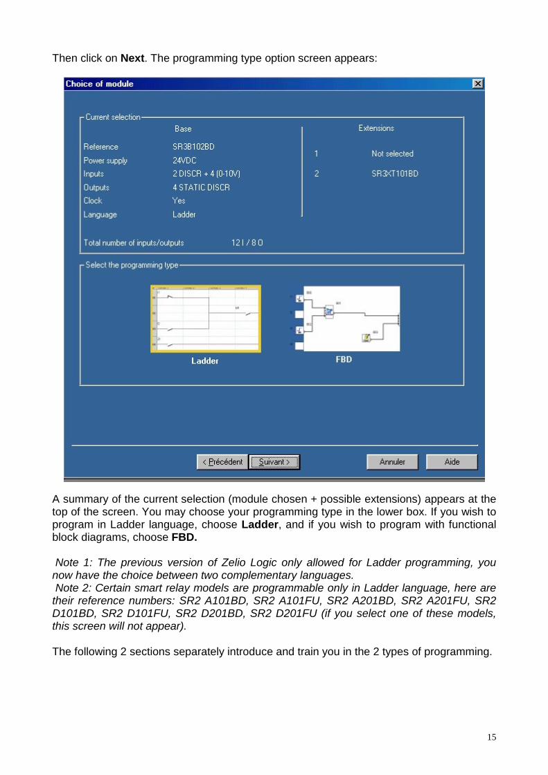
Then click on Next. The programming type option screen appears:
A summary of the current selection (module chosen + possible extensions) appears at thetop of the screen. You may choose your programming type in the lower box. If you wish toprogram in Ladder language, choose Ladder, and if you wish to program with functionalblock diagrams, choose FBD.
Note 1: The previous version of Zelio Logic only allowed for Ladder programming, younow have the choice between two complementary languages. Note 2: Certain smart relay models are programmable only in Ladder language, here aretheir reference numbers: SR2 A101BD, SR2 A101FU, SR2 A201BD, SR2 A201FU, SR2D101BD, SR2 D101FU, SR2 D201BD, SR2 D201FU (if you select one of these models,this screen will not appear).
The following 2 sections separately introduce and train you in the 2 types of programming.
16
4.2 LEARNING IN LADDER LANGUAGE4.2.1 Getting started
4.2.1.1 The simplicity of Ladder languageZelio Logic is programmable in Ladder language. This type of programming allows you tocarry out combinational logic functions. In this way, you may program your applicationswith Zelio Soft 2 or from its integrated programming screen and keyboard.
4.2.1.2 Accessing Zelio Soft helpThere is help available in the menu bar of Zelio Soft 2 that you may access by clicking onmenu ? then on Help, or by clicking directly on the icon available in the tool bar.To directly access Help concerning a function in use, click on ? in the function's parameterwindow (which you may access by double-clicking on the function).
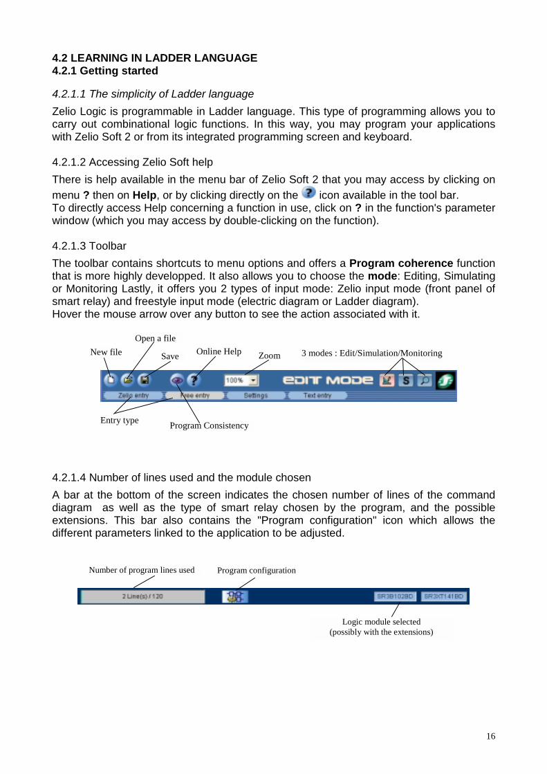
4.2.1.3 ToolbarThe toolbar contains shortcuts to menu options and offers a Program coherence functionthat is more highly developped. It also allows you to choose the mode: Editing, Simulatingor Monitoring Lastly, it offers you 2 types of input mode: Zelio input mode (front panel ofsmart relay) and freestyle input mode (electric diagram or Ladder diagram).Hover the mouse arrow over any button to see the action associated with it.
New file
Entry type Program Consistency
Open a file
Save Online Help Zoom 3 modes : Edit/Simulation/Monitoring
4.2.1.4 Number of lines used and the module chosenA bar at the bottom of the screen indicates the chosen number of lines of the commanddiagram as well as the type of smart relay chosen by the program, and the possibleextensions. This bar also contains the "Program configuration" icon which allows thedifferent parameters linked to the application to be adjusted.
Program configurationNumber of program lines used
Logic module selected(possibly with the extensions)

17
4.2.2 Writing a program in Ladder language
4.2.2.1 Modes and types of enteringWhen you have chosen your module and Ladder language, you are ready to build yourapplication.The selected Zelio Logic reference appears in the lower right (1):
(1)
With the software program, you may choose to program in Manual Data Entry or in ZelioData Entry.The default is Manual Data Entry: A wiring sheet limiting the areas reserved for thecontacts and for the coils (one only at the end of each line) appears on the screen.Zelio data entry is identical to keyboard data entry in integrated programming. Therefore,the instructions for this type of data entry are the same as for the front panel programming.To select this data entry, click on the corresponding tab (1):
(1) (2)
When you are in Manual data entry, you may visualize the this diagram in Laddersymbols or Electric symbols by selecting the desired symbol in the View menu.
This program has three modes: Edition mode (1), Simulation mode (2) and Monitoringmode (3). They may be selected in the Mode menu or from the toolbar in the upper right.The selected mode appears to the left of the 3 icons (4):
(1)
(4)
(3)(2)
Edition mode is the mode in which you may edit the program and the supervision window.This is the default mode. Simulation mode allows you to simulate the program beforetransferring it to the module. Monitoring mode enables you to visualize the input andoutput statuses of the module in real time.
A Supervision window is available for Simulation mode and Monitoring mode. Thiswindow offers you the possibility of vizualizing the inputs/outputs that you have previouslychosen and placed. This allows you to see the essential of the program to ensure anefficient tracking. Drawing functions enable you to illustrate the application.

18
4.2.2.2 Edit Mode: Programming the applicationEntering a program on the wiring sheetWhen you have selected your module type and Ladder language, a wiring sheet thenappears:
The default is Edition mode Manual Data Entry: The diagram is divided in columns,which allow you to distinguish the type of block to be placed. The first five columns arereserved for the contacts (yellow), the sixth allows you to place the output coil (blue). Thelast column is reserved for entering commentaries associated with each line. The dottedlines are lines where it is possible to wire in order to link functions with each other and tocarry out the elementary logic functions ET and OU
To create a block on the sheet, choose the block type by pointing to the correspondingicon at the bottom of the sheet:
(1) Discrete Input I (7) Counter comparator(2) Front panel button (8) Analog comparator (3) Auxiliary relay M (9) Weekly clock(4) Output Q (10) Display(5) Timer (11) Backlighting(6) Counter (12) Daylight Savings Summer/Winter

19
The list of available elements is displayed when you point to each icon:
The comment cell allows you to associate a name with each element (double click on thezone)
Click and drag the blocks to put them into place on the wiring sheet. The $$$$ symbolappears when it is impossible to place the block in a given zone.
For example, if you have just clicked and dragged 12 to place it on the wiring sheet, the $$$$symbol will appear when you try to place it as a coil, indicating that it may only be placedas a contact (also indicated by a color code)
Continue placing the other blocks in the same manner. To wire the reciprocal function (forexample i1 for the reciprocal input I1), either select the block by clicking on it (yellowbackground will appear) and press the space bar, or right click on the mouse and selectthe reciprocal function. Connections are made by clicking on the dotted line cells that youwish to wire.The charts corresponding to functions containing different types of inputs/outputs appearas follows:
The different input/output-type possibilities appear in the chart. When one of them hasbeen placed and it can be used only once (example: coil reset RQ2), the correspondingcell is grayed in and it is impossible to use it again.
Note: On the wiring sheet, it is possible to review the different types of output coils byclicking on the box (yellow background will appear when selected) and pressing the spacebar.
20
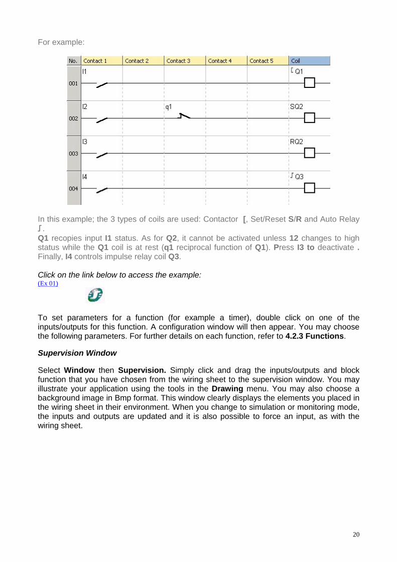
For example:
In this example; the 3 types of coils are used: Contactor [, Set/Reset S/R and Auto Relay!!!!.Q1 recopies input I1 status. As for Q2, it cannot be activated unless 12 changes to highstatus while the Q1 coil is at rest (q1 reciprocal function of Q1). Press I3 to deactivate .Finally, I4 controls impulse relay coil Q3.
Click on the link below to access the example:(Ex 01)
To set parameters for a function (for example a timer), double click on one of theinputs/outputs for this function. A configuration window will then appear. You may choosethe following parameters. For further details on each function, refer to 4.2.3 Functions.
Supervision Window
Select Window then Supervision. Simply click and drag the inputs/outputs and blockfunction that you have chosen from the wiring sheet to the supervision window. You mayillustrate your application using the tools in the Drawing menu. You may also choose abackground image in Bmp format. This window clearly displays the elements you placed inthe wiring sheet in their environment. When you change to simulation or monitoring mode,the inputs and outputs are updated and it is also possible to force an input, as with thewiring sheet.
21
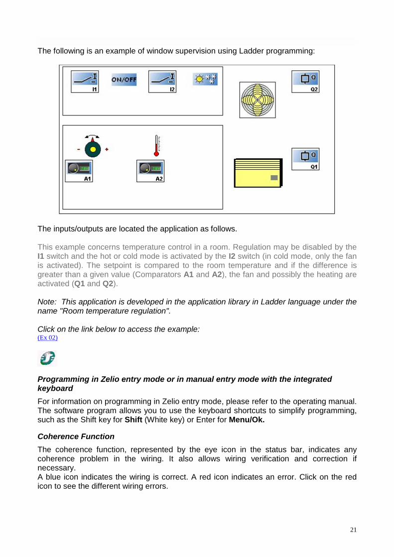
The following is an example of window supervision using Ladder programming:
The inputs/outputs are located the application as follows.
This example concerns temperature control in a room. Regulation may be disabled by theI1 switch and the hot or cold mode is activated by the I2 switch (in cold mode, only the fanis activated). The setpoint is compared to the room temperature and if the difference isgreater than a given value (Comparators A1 and A2), the fan and possibly the heating areactivated (Q1 and Q2).
Note: This application is developed in the application library in Ladder language under thename "Room temperature regulation".
Click on the link below to access the example:(Ex 02)
Programming in Zelio entry mode or in manual entry mode with the integratedkeyboardFor information on programming in Zelio entry mode, please refer to the operating manual.The software program allows you to use the keyboard shortcuts to simplify programming,such as the Shift key for Shift (White key) or Enter for Menu/Ok.
Coherence FunctionThe coherence function, represented by the eye icon in the status bar, indicates anycoherence problem in the wiring. It also allows wiring verification and correction ifnecessary.A blue icon indicates the wiring is correct. A red icon indicates an error. Click on the redicon to see the different wiring errors.

22
Blue Icon: NTR
Red Icon: Wiring problem, click on the icon to find out more
Program configurationProgram configuration allows you to customize your file by adding the project name andauthor. It is also possible to adjust certain configuration settings and to choose the dateformat.Click on the corresponding icon in the lower bar to access programconfiguration.
4.2.3 Functions
Note: The following descriptions are illustrated with functional examples.
Click on the icon to access the descriptions.
If Zelio Soft 2 software is installed, click on the link to open the program. You may thenselect simulation mode (1) and start the module (RUN) (2).
(1)
(2)
For further details on a function described below, refer to Help: Double-click on the blockand then on ?
4.2.3.1 Discrete InputsDiscrete Inputs I Discrete-type inputs (I1,I2,…) and mixed inputs (discrete or analog) (IB, IC…) In
Ladder programming, a mixed input placed on a contact is always discrete. The analogcomparator function allows the mixed input to be used as an analog ouput. All analoginputs take 0 to 10 V input voltage, corresponding to a value of 0 to 255.
Buttons You may use 4 Zelio Logic front-panel buttons (Z1, Z2, Z3, Z4) in your
application. Unlike the physical inputs I, they do not have connection terminals.
Note 1: Zx keys can not be used if locked (see APPLICATION TRANSFER for furtherdetails).Note 2: When the module is running and you wish to use the Zx keys in the program,access the INPUTS-OUTPUTS screen and simultaneously press Shift (White key) andZ1, Z2, Z3 or Z4.

23
4.2.3.2 Outputs Q OutputsDiscrete-type outputs can be used either as coils or contacts.
♦ Use as coil:
[ Q (Contactor): The coil is energized if the contacts to which it is connected are closed.!!!!Q (Impulse relay): Impulse energizing, the coil is energized by a change of state. Itsfunction is identical to that of an impulse relay.SQ (Set) : "Set" (latch) or triggered coil. This coil is triggered as soon as the contacts thatare connected to it are closed. It remains triggered even if the contacts are no longerclosed.RQ (Reset) : "Reset" or (unlatch) or deactivated coil. This coil is deactivated as soon asthe contacts that are connected to it are closed. It remains inactive even if the contacts areno longer closed.
♦ Used as contact:
Q (Normal function) or q (Reciprocal function): physical output from the smart relay. Anoutput can be used as a contact to determine its state at a given time.
Example 1:Q1--------[ Q2Q2 duplicates input Q1 status.
Example 2:q1--------[ Q2Q2 output will always be reciprocal to Q1 status.
Note: The [ and !!!!, SET and RESET functions must be used once and once only for eachcoil in a control diagram.Additionally, if you use a SET (S function), a control diagram line must always be providedfor disabling this coil using a RESET (R function).If this is not done, there will be always the risk of generating unexpected switch statusesduring operation.
Auxiliary M Relays (or internal memory) The auxiliary relays operate just like the Q output coils. The only difference is
that they do not have any connection terminals. They are used to save or forward a state.The saved or forwarded state will then be used as the assigned contact.
For example:
I1----------[ M1M1--------[ Q1
Activation of input I1 activates Q1 output, via M1.
24
4.2.3.3 Block FunctionsBoolean Function The control diagram entry mode allows you carry out Boolean functions by using theelementary logic functions AND and OR:
I1—I2———Q1 Associated logic equation: Q1=I1xI2, AND Logic
I1—I2———Q1 Associated logic equation: Q1=I1+I2, OR logicI2—|
Function i, the opposite of I, produces NO. This makes it possible to produce manydifferent functions.
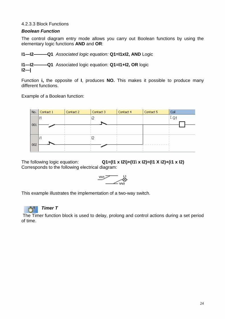
Example of a Boolean function:
The following logic equation: Q1=(I1 x I2\)+(I1\ x I2)=(I1 X i2)+(i1 x I2)Corresponds to the following electrical diagram:
This example illustrates the implementation of a two-way switch.
Timer T The Timer function block is used to delay, prolong and control actions during a set periodof time.
25
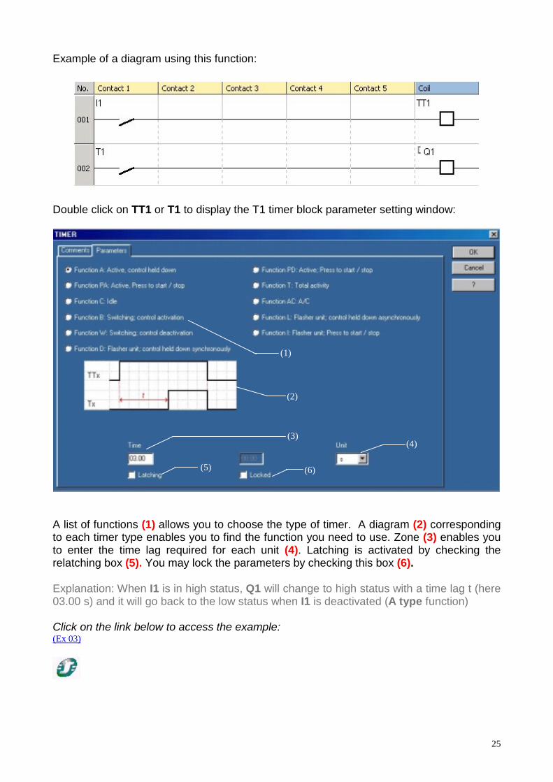
Example of a diagram using this function:
Double click on TT1 or T1 to display the T1 timer block parameter setting window:
(1)
(2)
(4)
(6)(5)
(3)
A list of functions (1) allows you to choose the type of timer. A diagram (2) correspondingto each timer type enables you to find the function you need to use. Zone (3) enables youto enter the time lag required for each unit (4). Latching is activated by checking therelatching box (5). You may lock the parameters by checking this box (6).
Explanation: When I1 is in high status, Q1 will change to high status with a time lag t (here03.00 s) and it will go back to the low status when I1 is deactivated (A type function)
Click on the link below to access the example:(Ex 03)

26
There are 3 main types of timers:
• Type A: Active, Control Held Down
For example: Delay the second motor start-up to limit energy consumption.
Click on the link below to access the example:(Ex 03)
• Type T: Total Activity Accumulator
For example: Request replacement of equipment when recommended service life isexceeded.
Click on the link below to access the example:(Ex 04)
• Type L or Li: Flasher Unit, Control Held Down/Asymmetrical
For example: Control a sound signal and create an alarm sound.
Click on the link below to access the example:(Ex 05)
Other types of timers may be used (11 types of timers)Each timer type possesses an input control (TT) and an input reset (RT).
"LATCHING" Save data function available.

27
CounterThis function enables you to upcount or downcount pulses, until a value preset in
the parameter setting window has been reached.
The block function Counter contains a count input (CC) (each time the coil is energized,the counter is incremented or decremented by 1 depending on the chosen counterdirection), a Reset input (RC), a counter direction input (DC) (the block downcounts if thisinput is activated) and a C output that enables you to know what level is controlled by thecounter. When the preset value has been reached, this output goes to 1 until it is zeroed orthe counting direction changes. The counting value and the preset value can be visualizedon the module screen.
Diagram produced using this function:
The parameter window is as follows:
(2)
(1)
(4)(3)

28
Field (1) enables you to enter the value to be reached (preset value). In (2), you maychoose between counting up to the preset value or counting down from the preset value.Latching is activated by checking the latching box (3). Check box (4) to lock theparameters.
Explanation: Every time I1 is pressed, the counter is incremented by 1. Pressing on 12changes the counter direction (DC1), the counter counts down. When the preset value isreached (here 5), C1 will be in high status, as will Q1 output.In a parking lot for example, each car input activates I1 and each output activates 12.When the parking lot is full, the Q1 output blocks the input.
Click on the link below to access the example:(Ex 06)
"LATCHING" Save data function available.
Fast Counter
Counter Comparator
Analog ComparatorAvailable only in modules with analog outputs.
This function block is used in applications using analog data, and enables you to comparea measured analog value and an internal value, or two measured analog values.The comparison result is used as a contact.This function is shown in the diagrams by the letter A (a for the reciprocal function).
Diagram produced using this function:

29
Parameters for the A1 block are shown as follows (double click on A1):
(1)
(2)
(4)
(3)
(5)
(6)
Different comparison operators may be used (1). Use fields (2) to select the 2 values to becompared. The values in use are the analog inputs (up to 6 according to the model) andthe reference value entered in field (3) (between 0.0 and 9.9 V). Field (4) does not appearuntil you select the operator "+-H"; this field will then enable you to enter the hysteresisvalue. Frame (5) summarizes the operation carried out according to the operators andoperands chosen. Cell (6) can be used to lock the parameters.
Explanation: Contact A1 is closed when the value of analog input IB equals or exceeds thevalue of IC. Output Q1 is now active.For example, in a room, when the temperature (analog input IB) exceeds the IC setpoint,the Q1 fan will start up.
Click on the link below to access the example:(Ex 07)
Here are 2 examples of formulas and their interpretation:
• Value 1 = Value 2with Value 1=ID and Value 2=Reference Value=5.6V
Contact A1 is closed when the value of analog input ID equals or exceeds the referencevoltage entered. In this case, 5.6 V.
Click on the link below to access the example:(Ex 08)
• Value 1 – H <= Value 2 <= Value 1 + Hwith Value 1=ID and Value 2=IC and Hysteresis (H)=2.3 V
30
Contact A1 is closed when the value of analog input IC is between ID - 2.3 V andID + 2.3 V.
Click on the link below to access the example:(Ex 09)
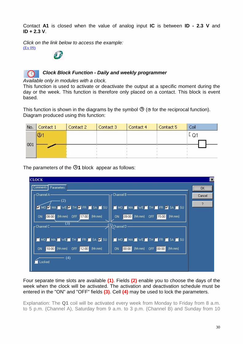
Clock Block Function - Daily and weekly programmer Available only in modules with a clock.This function is used to activate or deactivate the output at a specific moment during theday or the week. This function is therefore only placed on a contact. This block is eventbased.
This function is shown in the diagrams by the symbol !!!! (!!!! for the reciprocal function).Diagram produced using this function:
The parameters of the !!!!1 block appear as follows:
(2)
(1)
(4)
(3)
Four separate time slots are available (1). Fields (2) enable you to choose the days of theweek when the clock will be activated. The activation and deactivation schedule must beentered in the "ON" and "OFF" fields (3). Cell (4) may be used to lock the parameters.
Explanation: The Q1 coil will be activated every week from Monday to Friday from 8 a.m.to 5 p.m. (Channel A), Saturday from 9 a.m. to 3 p.m. (Channel B) and Sunday from 10

31
a.m. to 12 p.m. (Channel C). Channel D was not used in this example. This clock could beused, for example, to define the hours during which a building is open.
Click on the link below to access the example:(Ex 10)
Display function Available only in modules with a display system.
Display screen backlighting.Available only in modules with backlighting.
When activated, the function acts as an output and ensures display lighting.
Daylight Savings Change Summer/WinterAvailable only in modules with a clock
The output for this function is OFF when winter daylight saving time applies, and ON whensummer time applies. The switch from winter to summer time is displayed on the screen.
32
4.3 LEARNING TO USE FBD (FUNCTIONAL BLOCK DIAGRAM) LANGUAGE4.3.1 Getting started
4.3.1.1 FBD: A language offering multiple possibilitiesZelio Logic may be programmed in FBD (Function Block Diagram) language, a graphiclanguage offering multiple possibilities. With Zelio Logic, you may also add SFC-Grafcetfunctions to your application.
4.3.1.2 Accessing HelpIn Zelio Soft 2, you may access Help from the menu bar by clicking on the ? menu, thenon Help, or by clicking directly on the icon available in the tool bar.To directly access Help for a function in use, click on ? in the function parameter window(access by double-clicking on the corresponding block).
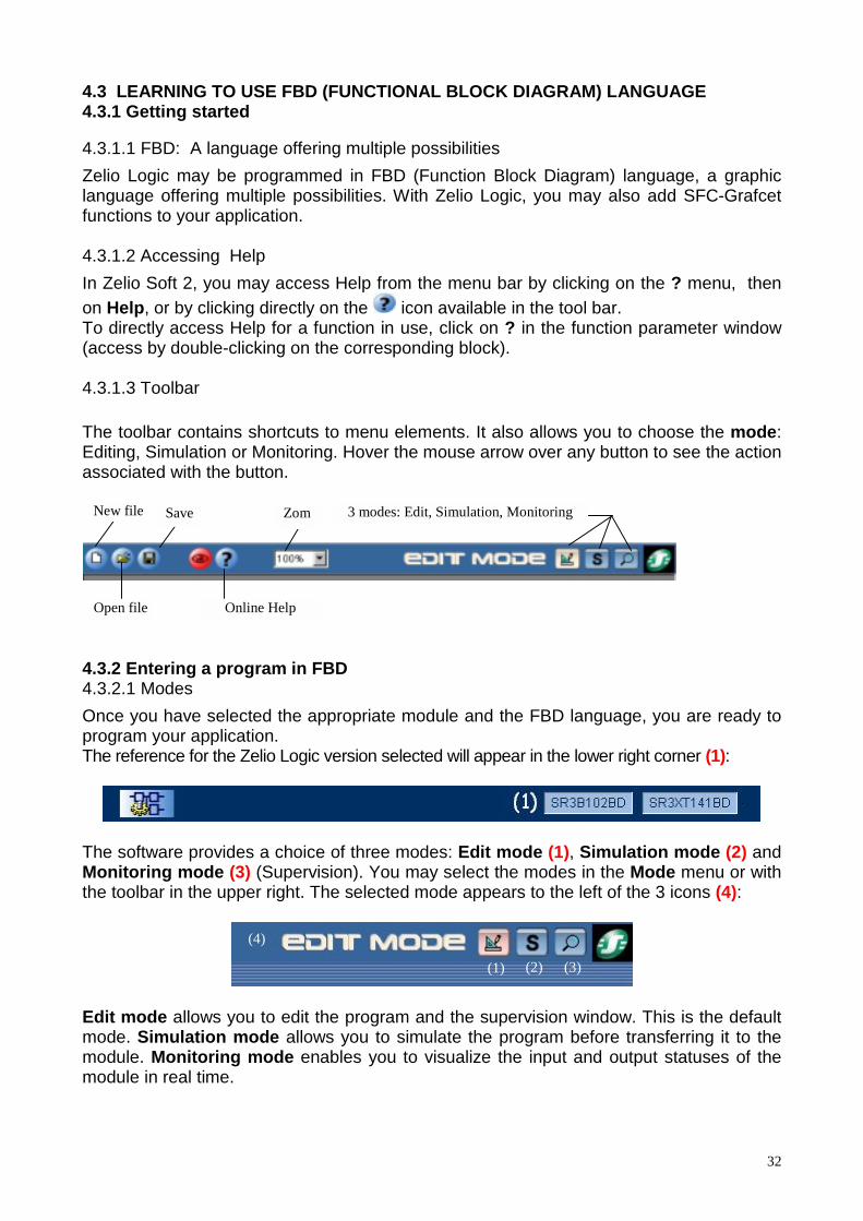
4.3.1.3 Toolbar
The toolbar contains shortcuts to menu elements. It also allows you to choose the mode:Editing, Simulation or Monitoring. Hover the mouse arrow over any button to see the actionassociated with the button.
New file Save
Open file
Zom 3 modes: Edit, Simulation, Monitoring
Online Help
4.3.2 Entering a program in FBD4.3.2.1 ModesOnce you have selected the appropriate module and the FBD language, you are ready toprogram your application.The reference for the Zelio Logic version selected will appear in the lower right corner (1):
The software provides a choice of three modes: Edit mode (1), Simulation mode (2) andMonitoring mode (3) (Supervision). You may select the modes in the Mode menu or withthe toolbar in the upper right. The selected mode appears to the left of the 3 icons (4):
(1)
(4)
(3)(2)
Edit mode allows you to edit the program and the supervision window. This is the defaultmode. Simulation mode allows you to simulate the program before transferring it to themodule. Monitoring mode enables you to visualize the input and output statuses of themodule in real time.
33
A Supervision window is available in simulation and supervision mode. This windowallows you to visualize the inputs/outputs that you have previously chosen and placed.This allows you to have a permanent overview of the application to ensure efficientmonitoring. Drawing functions can be used to illustrate the application.
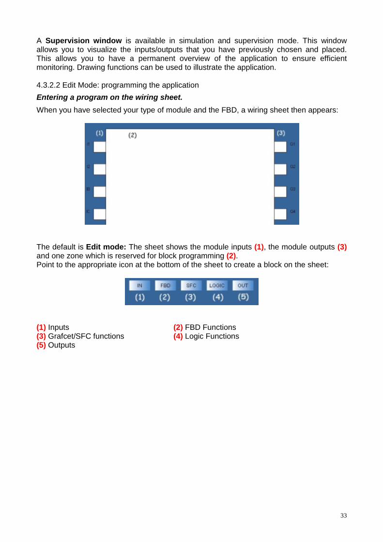
4.3.2.2 Edit Mode: programming the applicationEntering a program on the wiring sheet.When you have selected your type of module and the FBD, a wiring sheet then appears:
The default is Edit mode: The sheet shows the module inputs (1), the module outputs (3)and one zone which is reserved for block programming (2).Point to the appropriate icon at the bottom of the sheet to create a block on the sheet:
(1) Inputs (2) FBD Functions(3) Grafcet/SFC functions (4) Logic Functions(5) Outputs

34
You may see the list of available elements by placing the mouse pointer over one of theseicons:
Click and drag the blocks to put them into place on the wiring sheet. The $$$$ symbolappears when it is impossible to place the block into a given zone.
After having placed the various blocks, you can interconnect them : click and drag from theoutput > of the first block to the input > of the second block then release the mouse button.To build your application :
Select the input blocks and place them on the input lug, select the output blocks and placethem on the output lugs. Then select the function blocks, and wire the different points.Double click on the functions to configure them.
It is possible to change the input or output type. This option does not change anythingfrom an operating point of view.
If you want to change an input or output type, just double click on the icon and choose analias.
You can add a commentary and drawings on the wiring sheet. To do so use the Drawmenu.
For example: If you want to control car park entrances/exits. Each entrance I1 activatesthe light for 1 minute (output Q2) and increments the counter. Each exit decrements it.When the car park is full (25 cars) an indicator lamp lights (output Q3) and the moduledisplays ‘’CAR PARK FULL’’ ». In addition, when the temperature exceeds a threshold, afan starts up (output Q4)

35
Click on the link below to access the example:(Ex 11)
Supervision WindowSelect Window then Supervision. Simply click and drag the inputs/outputs and blockfunction that you have chosen from the wiring sheet to the supervision window. You mayillustrate your application using the tools in the Drawing menu. You may also choose abackground image in Bmp format. This window clearly displays the elements you placed inthe wiring sheet in their environment. When you go into simulation or monitoring mode, theinputs and outputs are updated. It is also possible to force an input in the same way as inthe edit window.
Program configurationThe program configuration allows you to customize your file by giving the project nameand author, and it is also possible to adjust certain configurations and choose the dateformat.Click on the corresponding icon in the lower bar to access the programconfiguration.

36
4.3.3 FunctionsNote: The following descriptions are illustrated with functional examples.
Click on the icon to access the descriptions.If Zelio Soft 2 software is installed, click on the link to open the program. You may thenselect simulation mode (1) and start the module (RUN) (2).
(1)
(2)
For further details on a function described below, refer to Help: Double-click on the blockand then on ?
4.3.3.1 InputsTOR. Discrete Inputs The application can be customized by selecting another icon to show a presence
detector or a backlit pushbutton for example.To change icons, place a Discrete block on the wiring sheet, then double click on it.Different types of Discrete inputs are then offered.
Analog inputsThis type of input accepts an incoming voltage of 0 to 10 V corresponding to a value
of 0 to 255. The application can be customized by selecting another icon to show a temperaturesensor or a potentiometer for example.
Filtered inputsFiltered digital or analog inputs can be inserted in the wiring. These types of inputs can beused to eliminate parasites.
Integer input (NUM IN)
ConstantsConstants can be inserted in the wiring.There are analog constants and digital constants.
1 sec clockA 1 second clock can be wired at the input.
37
Summer/winter time changeThe output for this function is OFF when winter daylight saving time applies, and ON whensummer time applies. The switch from winter to summer time is displayed on the screen.
ButtonsThe 4 buttons of the front panel of the Zelio, Z1, Z2, Z3, Z4 can be used in yourapplication.
Input examples
Click on the link below to access the example:(Ex 12)
4.3.3.2 OutputsDiscrete output The application may be customized by selecting another icon to show, for example,
a fan or heating resistor.To change icons, place a Discrete block on the wiring sheet, then double click on it.Differents types of Discrete outputs are then offered
Integer Output (NUM OUT)
Backlight outputThis output is used to drive the backlighting of the module screen.
Examples of outputs
Click on the link below to access the example:(Ex 13)
4.3.3.3 FBD (Function Block Diagram) Function blocksNote: Simply double click on the block to access the corresponding function configuration.
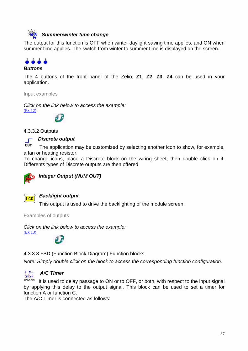
A/C TimerIt is used to delay passage to ON or to OFF, or both, with respect to the input signal
by applying this delay to the output signal. This block can be used to set a timer forfunction A or function C.The A/C Timer is connected as follows:

38
For example: to avoid overconsumption on boiler start-up, the heating elements areheated progressively. The first heating element is started up, followed by the secondelement 5 seconds later (or 50x100 ms), and likewise when the boiler is turned off.Click on the link below to access the example:(Ex 14)
"LATCHING" Save data function available.
B/H TimerIt is used to set the output signal to high status for a selected amount of time. It is
triggered by a input pulse (B function) or when the input is in high status (function H).
For example: A stairway timer. When the button is pressed, the light stays lit for 2 minutes.(function B).Click on the link below to access the example:(Ex 15)
"LATCHING" Save data function available.
BW TimerIt supplies a pulse lasting one cycle on the leading or trailing edge or both edges of
an input according to the setting selected in the parameters.
BlinkerIt is used to generate pulses on the leading edge of the input.
"LATCHING" Save data function available.
BistableThe principle of this block is the well-known trip-switch mechanism. An initial pulse
suffices to set the output to 1 and a second pulse sets it to 0.
Flip-flopThis is an element composed of two inputs: R and S. R for Reset and S for Set. To
activate the output, the generation of a pulse on S suffices, to deactivate it a pulse must begenerated on R. The priority is used to define the status of the output when both inputs areset to 1.
Boolean FunctionIt accepts four inputs. The output reacts according to the truth table described in
39
the parameters.Double-click on the block, or right click and select the configuration window, to access theparameters of the Boolean function .
For example: Execution of the Boolean equation Q1= (I1+I2) x (I3+I4) = (I1 or I2) and (I3or I4)
Click on the link below to access the example:(Ex 16)
CamshaftThis function is used to create a cam programmer
’’LATCHING’’ Save data function available.
CounterThis function is used to count to a value specified in the configuration window. When thisvalue is reached, the output goes to 1 until reset if the fixed output is selected or for acertain amount of time if the pulse output is selected. The counting value and themaximum value can be visualized. It is possible to count from zero to the specified value(count up) or from the specified value to zero (count down)
The COUNT UP DOWN block is used to set the pre-selection value at the input, while itcan be programmed for the PRESET COUNT block.
For example: A machine produces parts. One part is produced per second. This is shownby a blinking function Li (OnT=1s, OffT=0.1s). The counter is incremented by 1 each timea part is produced. The machine stops when the number of pieces produced reaches 5,and an operator packages them. The operator presses the button again to reset thecounter and start production up again.Click on the link below to access the example:
(Ex 17)
"LATCHING" Save data function available.
Time counterThis function measures the length of the input’s 1 status. Past a pre-selected time,
the output changes status. For example, this block can be used as a maintenance alert ona machine.
"LATCHING" Save data function available.
40
Weekly and yearly programmerThis function is used to activate or deactivate the output at a given time during the
day, week or year. This block is event-based. To create an event, go the Parameters tab,and click on New to create a cycle. Choose the time when this event occurs, then specifythe status of the output for that instant. The event frequency can be selected. Use thecalendar to the right of the screen.
The Summary tab gives the description of the programmed events.
The gain functionThis function allows the use of a scale factor, it is applicable to all analog data.
Schmitt triggerThe output changes status if the input is less than the minimum value. The output
changes status again if the input is greater than the maximum value. If the input is inbetween both values, the output remains unchanged.
This function is used to situate a high threshold and a low threshold with respect to ananalog variable.
For example: To control room temperature, the heater is set to come on when thetemperature is 3°C below the setpoint and to turn off when the temperature goes 2°C overthe setpoint. A Schmitt trigger is used with room temperature, maximum setpoint (setpoint+ 2°C) and minimum setpoint (setpoint - 3°C) as input.Click on the link below to access the example:
(Ex 18)
Multiplexer functionThis function is used to select channel A or channel B as output.
Zone comparisonUsed for applications using analog data.
+ - x / operations The combination of these two blocks enables you to perform many operations withnumerical constants.
LCD DisplayThis block is used to display text or an integer on the LCD on the front panel of the
module. For example, a decimal can be displayed from an integer.
41
For example: We want to display the number of vehicles present in an underground carpark. If the maximum is reached (10 in this case), a message diplsays ‘’Car park full’’.
Click on the link below to access the example:(Ex 19)
Note: After switching to Simulation mode and starting up the module, select 3 Front Panelin the Window menu to display the module screen. On the module screen, select FBDdisplay by clicking once on the DOWN button then on Menu/Ok. The messages thenappear on the screen.
Comparison of two valuesThis block is used to compare two analog values using the operators =, >, >=, <,
<=, !=. The output is the Discrete type and it is activated if the comparison is true.
Module status functionThis function enables us to see the status of the module.
Archiving functionProviding several items of information at output, including the date and time, this
function is used to display and modify information on the screen.
"LATCHING" Save data function available.
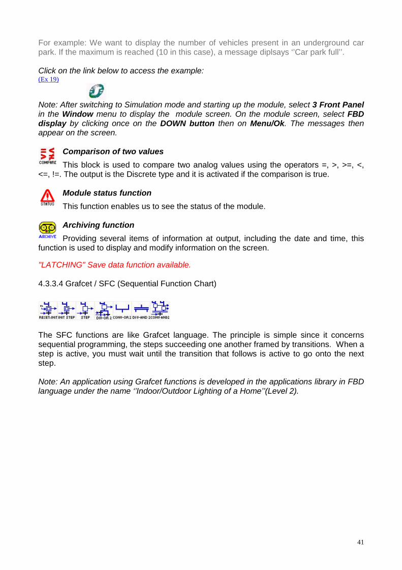
4.3.3.4 Grafcet / SFC (Sequential Function Chart)
The SFC functions are like Grafcet language. The principle is simple since it concernssequential programming, the steps succeeding one another framed by transitions. When astep is active, you must wait until the transition that follows is active to go onto the nextstep.
Note: An application using Grafcet functions is developed in the applications library in FBDlanguage under the name ‘’Indoor/Outdoor Lighting of a Home’’(Level 2).

42
4.3.3.5 Logic Functions
For example: Q1= [I1 AND (NOT I2)] OR [I3 NAND I4]
Click on the link below to access the example:(Ex 20)
Note: it is often possible to simplify wiring by replacing logic functions with a Booleanblock.

43
4.4 USING THE PROGRAMWhen you have entered your program in FBD or LADDER language, you can simulate itthen transfer it:
4.4.1 Simulation Mode: Program TestOnce your program is finished, you can test it by clicking on the ‘’S’’ icon at top right (1) orin the Mode menu then Simulation. To launch the program, click on (RUN) (2), as shownbelow:
(1)
(2)
Forcing is achieved by clicking on the function or the input or output pin. It is unnecessaryfor the module to be connected to the PC to perform the simulation.
4.4.2 Application Transfer4.4.2.1 Writing from a PC to Zelio LogicWhen your application is ready, you can transfer it into Zelio Logic.
To send a program to Zelio Logic, go to the Transfer menu, Transfer Program then clickon PC->Module.If the type of module selected is not compatible with the type of module connected, youcan change the type of module in Module then Choice of Module/Programming. It isalso possible to run a diagnosis of the module connected in Module then ModuleDiagnostic.If the module connected is in the RUN mode it is impossible to transfer the program. Youcan change it to the STOP mode using the software by selecting Transfer the STOPModule.

44
If the type of module selected is the same type as the module connected, the followingdialogue window opens:
(2)
(3)
(4)
(5)
(6)
In (2) you choose to render the Zx keys (that are used in input in the program) accessible.It is possible to protect the program present in the module with a password (3) that youenter (4). To save your application on your computer, check (5). Finally to launch themonitoring mode explained below, check (6).Then click on OK, the program is transferred.Note 1: The program that was present in the module before the transfer is overlayed bythe module.Note 2: When you have previously loaded a program in ladder language (if you program inFBD) or in FBD (if you program in Ladder) in the module (or on first use), the softwaremust update the module firmware. You will be offered the option to update during transfer.
4.4.2.2 Transfer of Zelio Logic program to the PCThis transfer function enables the retrieval of an application of the module using thesoftware.
From the software, go into the Transfer menu, Transfer Program then click on Module->PC. After a request for confirmation, the transfer is executed.
The software then loads the program present in the module.
Note: If the module program is locked, the code will be provided by the module before thetransfer.

45
4.4.3 Starting up the Module from the SoftwareClick on Transfer the RUN Module. However, when you transfer a program to themodule, it goes into the RUN mode automatically.
4.4.4 Mode Monitoring: Real time monitoringThe module is connected to the PC.This mode has the same characteristics as the simulation mode. The input or output statusof Zelio logic can be visualized or changed using the software. These inputs are visiblefrom the edit window as in the supervision window. The front panel is used to control theprocess and act on the keys remotely by selecting the front panel window.To launch the monitoring mode on program transfer, check the corresponding box in thetransfer window, or click on the icon in the upper right when the module is connected andcontains the corresponding program.
4.4.5 Print your applicationYou can print a complete file of your application. Select File, Print... (when you are in theEdit mode)
Select the parameters you need.Before printing, you can select File, View before print.
4.4.6 Set the time and date using the softwareWhen your application uses clocks, it is necessary to ensure that the module’s time iscorrect. It is possible to set the time using the software by clicking on Module then SetTime.
4.4.7 Password FunctionThe password protects access to a program. When you transfer your program to ZelioLogic, the write option window opens and you can check the ‘’Protect with password’’box. Once the password is activated, you may no longer write towards the module or readthe program without knowing this password. The program is protected. If you want toaccess the menu and reset the time for example, you will be asked to enter the password.
4.4.8 Front Panel LockThe front panel lock function is used to prohibit access to the menus. Locking is effectivewhen the program is on, but also when it is off. To switch the program on or off once thelock is activated, you must use the software.Nevertheless, Front Panel Lock does not prevent the use of the front panel buttons in aprogram.When you write your program in Zelio Logic, the write option window opens. Simply checkthe ‘’set lock on front panel of Module ‘’.
For further detail, use the on-line help or the operating manual.