Zappa, a Compliant Quasi-Passive Biped Robot with a Tail … · Zappa, a Compliant Quasi-Passive...
13
See discussions, stats, and author profiles for this publication at: https://www.researchgate.net/publication/221907935 Zappa, a Compliant Quasi-Passive Biped Robot with a Tail and Elastic Knees Chapter · March 2010 DOI: 10.5772/8834 · Source: InTech CITATIONS 0 READS 33 3 authors, including: Some of the authors of this publication are also working on these related projects: SLAM for endoscopic renal interventions View project Solar Decathlon competitions: Analysis of the results View project Alvaro Gutiérrez Universidad Politécnica de Madrid 45 PUBLICATIONS 914 CITATIONS SEE PROFILE Fernando Juan Berenguer Fundación PRODINTEC 16 PUBLICATIONS 36 CITATIONS SEE PROFILE All content following this page was uploaded by Alvaro Gutiérrez on 29 May 2014. The user has requested enhancement of the downloaded file.
Transcript of Zappa, a Compliant Quasi-Passive Biped Robot with a Tail … · Zappa, a Compliant Quasi-Passive...

See discussions, stats, and author profiles for this publication at: https://www.researchgate.net/publication/221907935
Zappa, a Compliant Quasi-Passive Biped Robot with a Tail and Elastic Knees
Chapter · March 2010
DOI: 10.5772/8834 · Source: InTech
CITATIONS
0READS
33
3 authors, including:
Some of the authors of this publication are also working on these related projects:
SLAM for endoscopic renal interventions View project
Solar Decathlon competitions: Analysis of the results View project
Alvaro Gutiérrez
Universidad Politécnica de Madrid
45 PUBLICATIONS 914 CITATIONS
SEE PROFILE
Fernando Juan Berenguer
Fundación PRODINTEC
16 PUBLICATIONS 36 CITATIONS
SEE PROFILE
All content following this page was uploaded by Alvaro Gutiérrez on 29 May 2014.
The user has requested enhancement of the downloaded file.
Zappa, a Compliant Quasi-Passive Biped Robot with a Tail and Elastic Knees 253
Zappa, a Compliant Quasi-Passive Biped Robot with a Tail and Elastic Knees
Félix Monasterio-Huelin, Álvaro Gutiérrez and Fernando J. Berenguer
0
Zappa, a Compliant Quasi-Passive Biped Robotwith a Tail and Elastic Knees
Félix Monasterio-Huelin and Álvaro GutiérrezUniversidad Politécnica de Madrid
Spain
Fernando J. BerenguerFundación Prodintec
Spain
1. Introduction
Bipeds are complex hybrid dynamical systems mixing both continuous and discrete-eventphenomena (Hurmuzlu et al., 2004). The main characteristic of biped walkers is the abruptkinematic change between the swing phase and the stance phase together with dynamical im-pacts. The main problem is how to achieve a rhythmical or periodical walk. Another difficultyof these robots is their high power requirement and, consequently, high energy consumption,which limits their autonomy. It can be attributed to the high number of actuated joints, andbecause energetic studies are not typically considered during the movement’s planning.Different studies focusing on the construction of locomotion controllers for completely actu-ated legged robots are found in the literature. These studies are mainly oriented to solve trajec-tory generation problems for the active control centered approach. In (Boeing & Bräunl, 2004)the authors show there is an example of this methodology showing that an impedance controlis better than the computed torque method. However, the conventional approach has beenquestioned by researchers inspired by biomechanical models (Kuo, 2007; McMahon, 1984).The discovery of McGeer about passive dynamic walking by building a biped without anymotors or sensors (McGeer, 1990), opens the doors to a new design concept based on morpho-logical considerations. Moreover, the interaction between morphology and control is a topic ofactual researches and debates in robotics (Pfeifer & Bongard, 2007). Therefore, exploiting theintrinsic passive dynamics has many advantages compared to the classical two-part method-ology (trajectory generation and active controller). Two of them are the energy consumptionreduction (the energetic cost is produced in step-to-step transitions) and the simplicity of con-trol (low computational cost). Nevertheless, some theoretical and practical studies (Collins &Ruina, 2005) show that it is difficult to achieve the complex dynamics exhibited by humansand animals taking into account only the properties of simple passive-dynamic walking, butmight help in the design of walking robots. In (Fumiya & Pfeifer, 2006) the authors show howto exploit the above mentioned passive properties of biped robots with the incorporation ofsensors.
15
Climbing and Walking Robots254
Typically, bipedal walking models assume rigid body structures. On the other hand, elasticmaterials seem to play an essential role in nature (Alexander, 2005). Therefore, spring-damperelements have been proposed as an initial solution for the compliant leg concept (Fumiya et al.,2009; Geyer & Seyfarth, 2006). These solutions can be extended with adaptable compliance(inverse of stiffness) mechanisms (Ham et al., 2007).A mechanism for a real biped robot with a tail (i.e. Zappa) was proposed in (Berenguer &Monasterio-Huelin, 2006) and improved in (Berenguer & Monasterio-Huelin, 2008). Zappa isa robot able to walk in flat floors of different positive and negative slopes (Gutiérrez et al.,2008). The tail is the only actuated limb that imposes an oscillatory movement of variablefrequency. By using this simple idea, it is possible to achieve an inverted pendulum trajectoryfor the legs. In this work, we propose a structural modification to Zappa, by adding elasticknees to the robot. This solution offers two main advantages: (i) a greater maneuverabilityand (ii) more compliant gaits.The paper is organized as follows. In Section 2 the robot kinematics are fully described. Insection 3 we propose a new controller applied to the robot’s tail. Moreover, we study the robotenergy consumption, and focus on the robot initialization, as a restriction to the walking per-formance. Section 4 describes the robot parameters along with performance graphs. Finally,Section 5 summarizes the most relevant conclusions and suggests future research directions.
2. The mechanism of the biped robot and the gait pattern
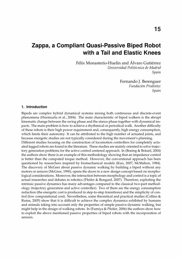
2.1 Kinematic DescriptionThe previous implementation of Zappa (see Figure 1) had two legs, each composed of a fourbars mechanism, four hip bars and a tail. The four bar mechanism includes a two bars femur,a one-bar foot and one hip’s bar. The hip is composed of four bars, two of them joining thetwo bars femur of each leg, and the others two joining the legs. The tail is attached to onebar of the hip. The frontal plane is the ZY plane, the sagittal one is the XY plane and thetransverse one is the ZX. To talk about the mechanism, we describe the following nomencla-ture as an example: A represents the line of the ankles, and AL and AR the left and right Alines respectively. When needed we will write AFL and ABL for the front and back of ALbars respectively. Figures 2a, 2b and 3a show the disposition of all bars and rotational joints.The foot has four possible contact points (C) with the floor (or ground, G) as depicted in Fig-ure 3b. To start walking, it is enough to move the tail around the Y axis and to fix a spring tothe ABL and ABR ankles. In Zappa this movement is managed by a DC servomotor with aposition sensor controlling the tail and an extensional spring holding the back femur and thefoot. Nevertheless, in simulations we use a torsional spring for the ankles and a controller togenerate torque for the tail joint, as explained in Section 2.2.The superior bar in the hip is added to avoid independent rotations of the legs around theX axis (see Figure 4). This bar is redundant in the stance phase. In general, this bar fixes akinematic constraint to the hip angle:
q1R − q1L = π (1)
This constraint could be relaxed adding a extensional spring (q5 = x5). The advantage ofrelaxing this constraint is to gain maneuverability to facilitate the rotation of the biped aroundthe Y axis, and to avoid the sliding of the feet in the stance phase. In this work, we do notstudy the different configurations. On the other hand, the spring has been adjusted to generateenough force to avoid this balancing.
Fig. 1. Zappa biped robot. Prototype without knees.
(a) (b) (c)
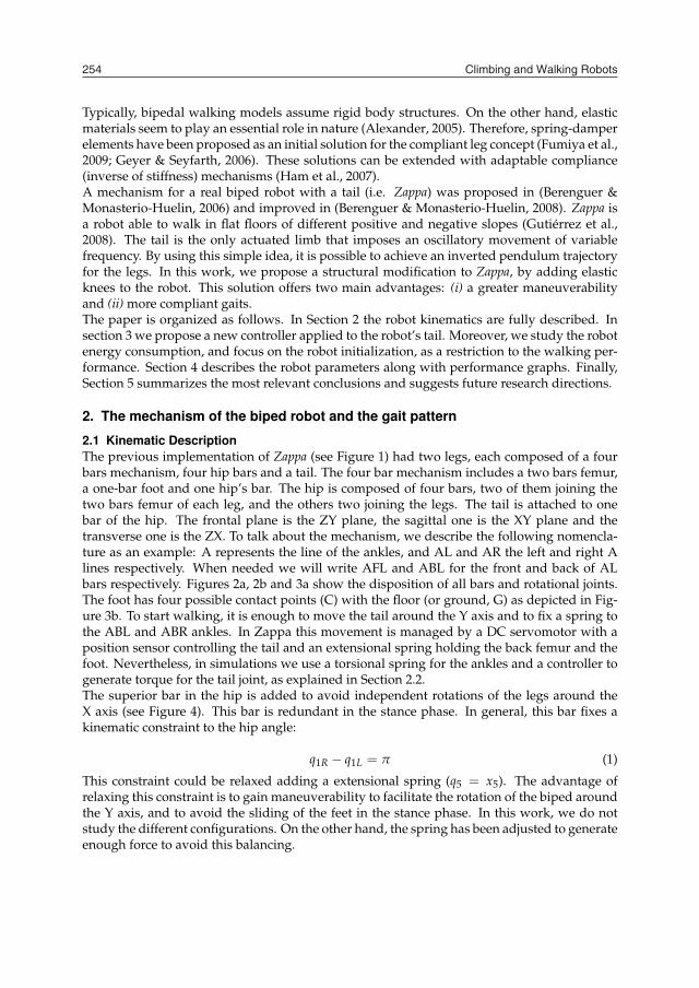
Fig. 2. Sagittal plane of a leg (a) without and (c) with knee. (b) Frontal plane of the hip barsand the tail.
For the stance phase there is a strong kinematic constraint that is avoided by producing aslight sliding of the feet in the Z direction, as depicted in Figure 5,
l2sin(q2R) + l1sin(q1) = l2sin(q2L) (2)
In the particular situation of q1 = 0, the sole solution is q2R + q2L = π or q2R = q2L. Therefore,the center of the hip bars will always lie in the midpoint between the feet. Furthermore, thedistance between the feet depends on one ankle angle: L = 2lcos(q2).To avoid the sliding, we propose to relax the latter kinematic constraint adding a knee. To dothis, we have divided the femur in two parts, from now on femur and tibia, as depicted inFigure 2c (q2). If the knee bar is rigid, each leg femur bars are parallel, and so are the tibiabars. The second kinematic constraint has been broken, but the pentagonal kinematic closedchain imposes a new constraint:
Zappa, a Compliant Quasi-Passive Biped Robot with a Tail and Elastic Knees 255
Typically, bipedal walking models assume rigid body structures. On the other hand, elasticmaterials seem to play an essential role in nature (Alexander, 2005). Therefore, spring-damperelements have been proposed as an initial solution for the compliant leg concept (Fumiya et al.,2009; Geyer & Seyfarth, 2006). These solutions can be extended with adaptable compliance(inverse of stiffness) mechanisms (Ham et al., 2007).A mechanism for a real biped robot with a tail (i.e. Zappa) was proposed in (Berenguer &Monasterio-Huelin, 2006) and improved in (Berenguer & Monasterio-Huelin, 2008). Zappa isa robot able to walk in flat floors of different positive and negative slopes (Gutiérrez et al.,2008). The tail is the only actuated limb that imposes an oscillatory movement of variablefrequency. By using this simple idea, it is possible to achieve an inverted pendulum trajectoryfor the legs. In this work, we propose a structural modification to Zappa, by adding elasticknees to the robot. This solution offers two main advantages: (i) a greater maneuverabilityand (ii) more compliant gaits.The paper is organized as follows. In Section 2 the robot kinematics are fully described. Insection 3 we propose a new controller applied to the robot’s tail. Moreover, we study the robotenergy consumption, and focus on the robot initialization, as a restriction to the walking per-formance. Section 4 describes the robot parameters along with performance graphs. Finally,Section 5 summarizes the most relevant conclusions and suggests future research directions.
2. The mechanism of the biped robot and the gait pattern
2.1 Kinematic DescriptionThe previous implementation of Zappa (see Figure 1) had two legs, each composed of a fourbars mechanism, four hip bars and a tail. The four bar mechanism includes a two bars femur,a one-bar foot and one hip’s bar. The hip is composed of four bars, two of them joining thetwo bars femur of each leg, and the others two joining the legs. The tail is attached to onebar of the hip. The frontal plane is the ZY plane, the sagittal one is the XY plane and thetransverse one is the ZX. To talk about the mechanism, we describe the following nomencla-ture as an example: A represents the line of the ankles, and AL and AR the left and right Alines respectively. When needed we will write AFL and ABL for the front and back of ALbars respectively. Figures 2a, 2b and 3a show the disposition of all bars and rotational joints.The foot has four possible contact points (C) with the floor (or ground, G) as depicted in Fig-ure 3b. To start walking, it is enough to move the tail around the Y axis and to fix a spring tothe ABL and ABR ankles. In Zappa this movement is managed by a DC servomotor with aposition sensor controlling the tail and an extensional spring holding the back femur and thefoot. Nevertheless, in simulations we use a torsional spring for the ankles and a controller togenerate torque for the tail joint, as explained in Section 2.2.The superior bar in the hip is added to avoid independent rotations of the legs around theX axis (see Figure 4). This bar is redundant in the stance phase. In general, this bar fixes akinematic constraint to the hip angle:
q1R − q1L = π (1)
This constraint could be relaxed adding a extensional spring (q5 = x5). The advantage ofrelaxing this constraint is to gain maneuverability to facilitate the rotation of the biped aroundthe Y axis, and to avoid the sliding of the feet in the stance phase. In this work, we do notstudy the different configurations. On the other hand, the spring has been adjusted to generateenough force to avoid this balancing.
Fig. 1. Zappa biped robot. Prototype without knees.
(a) (b) (c)
Fig. 2. Sagittal plane of a leg (a) without and (c) with knee. (b) Frontal plane of the hip barsand the tail.
For the stance phase there is a strong kinematic constraint that is avoided by producing aslight sliding of the feet in the Z direction, as depicted in Figure 5,
l2sin(q2R) + l1sin(q1) = l2sin(q2L) (2)
In the particular situation of q1 = 0, the sole solution is q2R + q2L = π or q2R = q2L. Therefore,the center of the hip bars will always lie in the midpoint between the feet. Furthermore, thedistance between the feet depends on one ankle angle: L = 2lcos(q2).To avoid the sliding, we propose to relax the latter kinematic constraint adding a knee. To dothis, we have divided the femur in two parts, from now on femur and tibia, as depicted inFigure 2c (q2). If the knee bar is rigid, each leg femur bars are parallel, and so are the tibiabars. The second kinematic constraint has been broken, but the pentagonal kinematic closedchain imposes a new constraint:
Climbing and Walking Robots256
(a) (b)
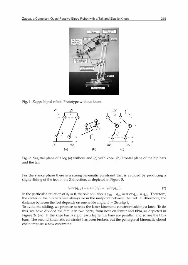
Fig. 3. (a) Transverse plane of the Central Hip and the Tail. (b) Three planes of a foot: jointswith the leg and contact points with the floor.
(a) (b)
Fig. 4. Hip superior bar added to avoid oscillations around the X axis.
(a) (b)
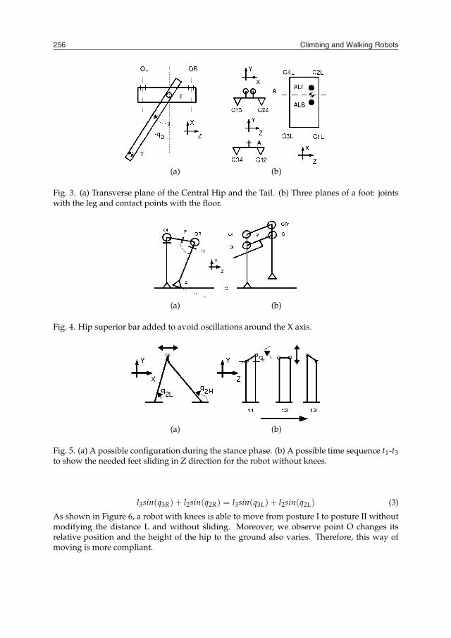
Fig. 5. (a) A possible configuration during the stance phase. (b) A possible time sequence t1-t3to show the needed feet sliding in Z direction for the robot without knees.
l3sin(q3R) + l2sin(q2R) = l3sin(q3L) + l2sin(q2L) (3)
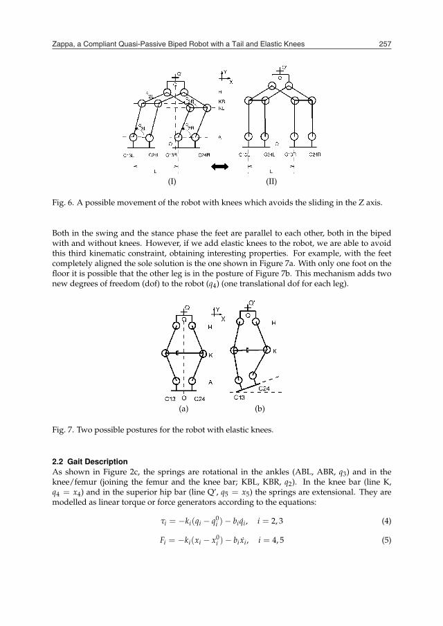
As shown in Figure 6, a robot with knees is able to move from posture I to posture II withoutmodifying the distance L and without sliding. Moreover, we observe point O changes itsrelative position and the height of the hip to the ground also varies. Therefore, this way ofmoving is more compliant.
(I) (II)
Fig. 6. A possible movement of the robot with knees which avoids the sliding in the Z axis.
Both in the swing and the stance phase the feet are parallel to each other, both in the bipedwith and without knees. However, if we add elastic knees to the robot, we are able to avoidthis third kinematic constraint, obtaining interesting properties. For example, with the feetcompletely aligned the sole solution is the one shown in Figure 7a. With only one foot on thefloor it is possible that the other leg is in the posture of Figure 7b. This mechanism adds twonew degrees of freedom (dof) to the robot (q4) (one translational dof for each leg).
(a) (b)
Fig. 7. Two possible postures for the robot with elastic knees.
2.2 Gait DescriptionAs shown in Figure 2c, the springs are rotational in the ankles (ABL, ABR, q3) and in theknee/femur (joining the femur and the knee bar; KBL, KBR, q2). In the knee bar (line K,q4 = x4) and in the superior hip bar (line Q’, q5 = x5) the springs are extensional. They aremodelled as linear torque or force generators according to the equations:
τi = −ki(qi − q0i )− biqi, i = 2, 3 (4)
Fi = −ki(xi − x0i )− bi xi, i = 4, 5 (5)
Zappa, a Compliant Quasi-Passive Biped Robot with a Tail and Elastic Knees 257
(a) (b)
Fig. 3. (a) Transverse plane of the Central Hip and the Tail. (b) Three planes of a foot: jointswith the leg and contact points with the floor.
(a) (b)
Fig. 4. Hip superior bar added to avoid oscillations around the X axis.
(a) (b)
Fig. 5. (a) A possible configuration during the stance phase. (b) A possible time sequence t1-t3to show the needed feet sliding in Z direction for the robot without knees.
l3sin(q3R) + l2sin(q2R) = l3sin(q3L) + l2sin(q2L) (3)
As shown in Figure 6, a robot with knees is able to move from posture I to posture II withoutmodifying the distance L and without sliding. Moreover, we observe point O changes itsrelative position and the height of the hip to the ground also varies. Therefore, this way ofmoving is more compliant.
(I) (II)
Fig. 6. A possible movement of the robot with knees which avoids the sliding in the Z axis.
Both in the swing and the stance phase the feet are parallel to each other, both in the bipedwith and without knees. However, if we add elastic knees to the robot, we are able to avoidthis third kinematic constraint, obtaining interesting properties. For example, with the feetcompletely aligned the sole solution is the one shown in Figure 7a. With only one foot on thefloor it is possible that the other leg is in the posture of Figure 7b. This mechanism adds twonew degrees of freedom (dof) to the robot (q4) (one translational dof for each leg).
(a) (b)
Fig. 7. Two possible postures for the robot with elastic knees.
2.2 Gait DescriptionAs shown in Figure 2c, the springs are rotational in the ankles (ABL, ABR, q3) and in theknee/femur (joining the femur and the knee bar; KBL, KBR, q2). In the knee bar (line K,q4 = x4) and in the superior hip bar (line Q’, q5 = x5) the springs are extensional. They aremodelled as linear torque or force generators according to the equations:
τi = −ki(qi − q0i )− biqi, i = 2, 3 (4)
Fi = −ki(xi − x0i )− bi xi, i = 4, 5 (5)
Climbing and Walking Robots258
where q0i and x0
i are the i-spring equilibrium position, ki the i-spring constant and bi the i-viscous damping coefficient.Selecting the springs is far from a trivial task as shown in (Gutiérrez et al., 2008). In thatwork, the authors studied a variable tuning for the ankle spring in the biped without kneesusing evolutionary optimization techniques. The fitness function was the travelled distancein a specified time and at different slopes of the floor. A mechanism that is able to changethe spring parameters in real time was proposed in (Ham et al., 2007) using two servomotors(in general it is possible to generate the spring torque or force with only one DC motor andan electrical current controller). In the present work we have empirically obtained constantparameters by means of computer simulations.One important question, not mentioned before, is related to the reaction forces between thefeet and the ground. This question is extremely important in walking robots because of thestrokes that occur when changing from the swing phase to the stance phase, and because theyare variables that show the biped stability.The total reaction force (FR) of the robot satisfies the following vectorial equation,
FR = M( ¨cm − g) (6)
where ¨cm is the acceleration of its center of mass referred to some inertial coordinates system,g the gravitational acceleration and M the mass of the robot. The Newton equation of a foot is
fR + fAB + fAF + mFg = mFaF (7)
where fR is the reaction force of one leg, mF the mass of the foot, fAB and fAF the forces exertedby the back femur (or tibias, for the robot with knees) and frontal femur respectively on thefoot (ankles AB and AF).Hence, FR = fRL + fRR. When the foot is on the floor aF = 0. In the other case fR = 0.Therefore, measuring aF is enough to know if one leg is on the floor except in the case ofelastic knees, because the foot may oscillate around the Z axis. Simulations made in this workconsider that the foot is in the air if all the reaction forces at each contact point in the threedirections of space (x,y,z) are zero. Figure 8 shows the timing of the moments of contact of feetwith the ground (represented as zero) overlapped with the reaction forces of each foot.For the computer simulations, we have modelled the contact point between the feet and thefloor as attractive forces that depend on the velocity of each foot contact point for the X andZ direction. For the Y direction, a stiffness factor has been added. This factor depends onthe position only when position and velocity are negative (Berenguer & Monasterio-Huelin,2007a).Most figures that follow have been overlapped with this timing to properly interpret them.The functioning of the biped robot is as follows: when q0 = 0 the robot remains standing.For µ(t) around π/2 the robot rises a leg while the other remains in the floor. In other words,the tail works as a dynamic counterweight varying q1. Because of the torque applied to thetail joint, the moment produced in the legs creates a pendular oscillation in both legs. Thisoscillation is produced around the ankle (A) for the foot on the floor and around the hip (H)for the foot in the air. This oscillation depends on all the springs of the robot. The potentialenergy stored in the springs acts as an energy generator allowing a compliant walking.To be more concise, we can distinguish a clear sequence of movements of point P (tail joint)during the turn of the tail. The swing phase begin lifting one leg when q0 = π/2 − µ untilπ/2, and provokes that Px > 0. From π/2 until q0 = π/2 − µ′ the swing phase continuesuntil the foot makes contact with the ground; hence Px > 0. In the stance phase Px changes
12.0 12.5 13.0 13.5 14.0 14.5 15.0Time(s)
Rea
ctio
n Fo
rce
(N)
040
010
2030
40
12.0 12.5 13.0 13.5 14.0 14.5 15.0Time(s)
Rea
ctio
n Fo
rce
(N)
040
010
2030
40
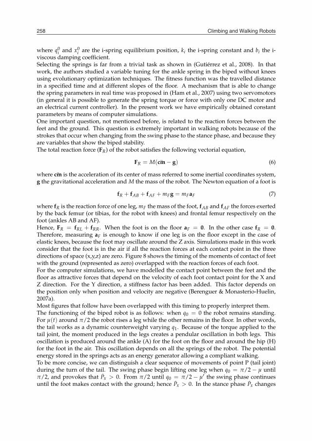
(a) (b)Fig. 8. Left (solid) and Right (dashed) feet reaction forces for a robot (a) without knees and (b)with elastic knees.
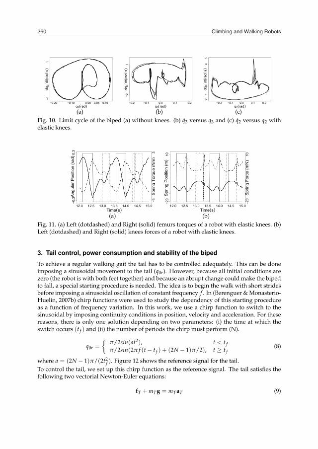
its sign until q0 = −π/2 + µ, repeating the cycle. Figure 9 shows this sequence. In Figure 10the limit cycle (q2 versus q2 for the robot without knees, q3 versus q3 and q2 versus q2 for therobot with elastic knees) of the biped gait pattern is shown. We define the limit cycle as asequence of steps used as an index of whole stability (Hobbelen & Wisse, 2007) in contrast tothe ZMP (Vukobratovic et al., 1990) that imposes local stability at every instant in time.In Figure 9 we show the Py kinematic equation when all the four contact points of the foot arein the floor. However, this is not the general case when the robot has elastic knees because Pydepends on the angle between the foot and the floor in the stance phase. Therefore, the bipedrobot with elastic knees walks raising the heel (line C13 in Figure 3b) of the swinging leg andfalls on it at the end of a step (in a similar way to human walking).
12.0 12.5 13.0 13.5 14.0 14.5 15.0Time(s)
q(ra
d)
y(cm
)
−0.5
00.
51.
5
4142
4445
12.0 12.5 13.0 13.5 14.0 14.5 15.0Time(s)
q(ra
d)
y(cm
)
−0.5
00.
51.
52
4142
4345
46
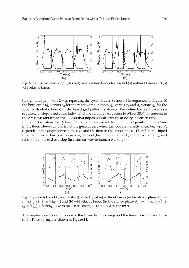
(a) (b)Fig. 9. q1L (solid) and Py (dotdashed) of the biped (a) without knees (in the stance phase PyL =l1 |sin(q1L)|+ l2sin(q2L)) and (b) with elastic knees (in the stance phase PyL = l1 |sin(q1L)|+l2sin(q2L) + l3sin(q3L) with no elastic knees, as explained in the text).
The angular position and torque of the Knee/Femur spring and the linear position and forceof the Knee spring are shown in Figure 11.
Zappa, a Compliant Quasi-Passive Biped Robot with a Tail and Elastic Knees 259
where q0i and x0
i are the i-spring equilibrium position, ki the i-spring constant and bi the i-viscous damping coefficient.Selecting the springs is far from a trivial task as shown in (Gutiérrez et al., 2008). In thatwork, the authors studied a variable tuning for the ankle spring in the biped without kneesusing evolutionary optimization techniques. The fitness function was the travelled distancein a specified time and at different slopes of the floor. A mechanism that is able to changethe spring parameters in real time was proposed in (Ham et al., 2007) using two servomotors(in general it is possible to generate the spring torque or force with only one DC motor andan electrical current controller). In the present work we have empirically obtained constantparameters by means of computer simulations.One important question, not mentioned before, is related to the reaction forces between thefeet and the ground. This question is extremely important in walking robots because of thestrokes that occur when changing from the swing phase to the stance phase, and because theyare variables that show the biped stability.The total reaction force (FR) of the robot satisfies the following vectorial equation,
FR = M( ¨cm − g) (6)
where ¨cm is the acceleration of its center of mass referred to some inertial coordinates system,g the gravitational acceleration and M the mass of the robot. The Newton equation of a foot is
fR + fAB + fAF + mFg = mFaF (7)
where fR is the reaction force of one leg, mF the mass of the foot, fAB and fAF the forces exertedby the back femur (or tibias, for the robot with knees) and frontal femur respectively on thefoot (ankles AB and AF).Hence, FR = fRL + fRR. When the foot is on the floor aF = 0. In the other case fR = 0.Therefore, measuring aF is enough to know if one leg is on the floor except in the case ofelastic knees, because the foot may oscillate around the Z axis. Simulations made in this workconsider that the foot is in the air if all the reaction forces at each contact point in the threedirections of space (x,y,z) are zero. Figure 8 shows the timing of the moments of contact of feetwith the ground (represented as zero) overlapped with the reaction forces of each foot.For the computer simulations, we have modelled the contact point between the feet and thefloor as attractive forces that depend on the velocity of each foot contact point for the X andZ direction. For the Y direction, a stiffness factor has been added. This factor depends onthe position only when position and velocity are negative (Berenguer & Monasterio-Huelin,2007a).Most figures that follow have been overlapped with this timing to properly interpret them.The functioning of the biped robot is as follows: when q0 = 0 the robot remains standing.For µ(t) around π/2 the robot rises a leg while the other remains in the floor. In other words,the tail works as a dynamic counterweight varying q1. Because of the torque applied to thetail joint, the moment produced in the legs creates a pendular oscillation in both legs. Thisoscillation is produced around the ankle (A) for the foot on the floor and around the hip (H)for the foot in the air. This oscillation depends on all the springs of the robot. The potentialenergy stored in the springs acts as an energy generator allowing a compliant walking.To be more concise, we can distinguish a clear sequence of movements of point P (tail joint)during the turn of the tail. The swing phase begin lifting one leg when q0 = π/2 − µ untilπ/2, and provokes that Px > 0. From π/2 until q0 = π/2 − µ′ the swing phase continuesuntil the foot makes contact with the ground; hence Px > 0. In the stance phase Px changes
12.0 12.5 13.0 13.5 14.0 14.5 15.0Time(s)
Rea
ctio
n Fo
rce
(N)
040
010
2030
40
12.0 12.5 13.0 13.5 14.0 14.5 15.0Time(s)
Rea
ctio
n Fo
rce
(N)
040
010
2030
40
(a) (b)Fig. 8. Left (solid) and Right (dashed) feet reaction forces for a robot (a) without knees and (b)with elastic knees.
its sign until q0 = −π/2 + µ, repeating the cycle. Figure 9 shows this sequence. In Figure 10the limit cycle (q2 versus q2 for the robot without knees, q3 versus q3 and q2 versus q2 for therobot with elastic knees) of the biped gait pattern is shown. We define the limit cycle as asequence of steps used as an index of whole stability (Hobbelen & Wisse, 2007) in contrast tothe ZMP (Vukobratovic et al., 1990) that imposes local stability at every instant in time.In Figure 9 we show the Py kinematic equation when all the four contact points of the foot arein the floor. However, this is not the general case when the robot has elastic knees because Pydepends on the angle between the foot and the floor in the stance phase. Therefore, the bipedrobot with elastic knees walks raising the heel (line C13 in Figure 3b) of the swinging leg andfalls on it at the end of a step (in a similar way to human walking).
12.0 12.5 13.0 13.5 14.0 14.5 15.0Time(s)
q(ra
d)
y(cm
)
−0.5
00.
51.
5
4142
4445
12.0 12.5 13.0 13.5 14.0 14.5 15.0Time(s)
q(ra
d)
y(cm
)
−0.5
00.
51.
52
4142
4345
46
(a) (b)Fig. 9. q1L (solid) and Py (dotdashed) of the biped (a) without knees (in the stance phase PyL =l1 |sin(q1L)|+ l2sin(q2L)) and (b) with elastic knees (in the stance phase PyL = l1 |sin(q1L)|+l2sin(q2L) + l3sin(q3L) with no elastic knees, as explained in the text).
The angular position and torque of the Knee/Femur spring and the linear position and forceof the Knee spring are shown in Figure 11.
Climbing and Walking Robots260
−0.20 −0.10 0.00 0.05 0.10q2(rad)
dq2
dt(ra
ds)
−11
−0.2 −0.1 0.0 0.1 0.2q3(rad)
dq3
dt(ra
ds)
−21
−0.2 −0.1 0.0 0.1 0.2q2(rad)
dq2
dt(ra
ds)
−21
45
(a) (b) (c)Fig. 10. Limit cycle of the biped (a) without knees. (b) q3 versus q3 and (c) q2 versus q2 withelastic knees.
12.0 12.5 13.0 13.5 14.0 14.5 15.0Time(s)
Ang
ular
Pos
ition
(rad
)
Spr
ing
Torq
ue (N
m)
−0.3
0.3
−33
12.0 12.5 13.0 13.5 14.0 14.5 15.0Time(s)
Spr
ing
Pos
ition
(m)
Spr
ing
Forc
e (m
N)
−20
10
−20
10
(a) (b)Fig. 11. (a) Left (dotdashed) and Right (solid) femurs torques of a robot with elastic knees. (b)Left (dotdashed) and Right (solid) knees forces of a robot with elastic knees.
3. Tail control, power consumption and stability of the biped
To achieve a regular walking gait the tail has to be controlled adequately. This can be doneimposing a sinusoidal movement to the tail (q0r). However, because all initial conditions arezero (the robot is with both feet together) and because an abrupt change could make the bipedto fall, a special starting procedure is needed. The idea is to begin the walk with short stridesbefore imposing a sinusoidal oscillation of constant frequency f . In (Berenguer & Monasterio-Huelin, 2007b) chirp functions were used to study the dependency of this starting procedureas a function of frequency variation. In this work, we use a chirp function to switch to thesinusoidal by imposing continuity conditions in position, velocity and acceleration. For thesereasons, there is only one solution depending on two parameters: (i) the time at which theswitch occurs (t f ) and (ii) the number of periods the chirp must perform (N).
q0r =
{π/2sin(at2), t < t fπ/2sin(2π f (t − t f ) + (2N − 1)π/2), t ≥ t f
(8)
where a = (2N − 1)π/(2t2f ). Figure 12 shows the reference signal for the tail.
To control the tail, we set up this chirp function as the reference signal. The tail satisfies thefollowing two vectorial Newton-Euler equations:
fT + mTg = mTaT (9)
0 1 2 3 4 5 6 7Time(s)
Ref
eren
ce S
igna
l
E.(1
0e−3
), S
EI.(
10e−
4)−4
4
−22
0 1 2 3 4 5 6 7Time(s)
E.(1
0e−3
), S
EI.(
10e−
4)
Ref
eren
ce S
igna
l
−44
−22
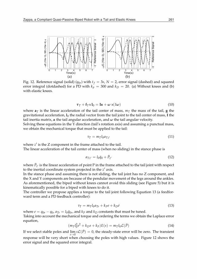
(a) (b)Fig. 12. Reference signal (solid) (q0r) with t f = 3s, N = 2, error signal (dashed) and squarederror integral (dotdashed) for a PD with kp = 300 and kD = 20. (a) Without knees and (b)with elastic knees.
τT + fTx l0 = Iα + ω x(Iω) (10)
where aT is the linear acceleration of the tail center of mass, mT the mass of the tail, g thegravitational acceleration, l0 the radial vector from the tail joint to the tail center of mass, I thetail inertia matrix, α the tail angular acceleration, and ω the tail angular velocity.Solving these equations in the Y direction (tail’s rotation axis) and assuming a punctual mass,we obtain the mechanical torque that must be applied to the tail:
τT = mTl0aTz′ (11)
where z′ is the Z component in the frame attached to the tail.The linear acceleration of the tail center of mass (when no sliding) in the stance phase is
aTz′ = l0q0 + Pz′ (12)
where Pz′ is the linear acceleration of point P in the frame attached to the tail joint with respectto the inertial coordinate system projected in the z′ axis.In the stance phase and assuming there is not sliding, the tail joint has no Z component, andthe X and Y components are because of the pendular movement of the legs around the ankles.As aforementioned, the biped without knees cannot avoid this sliding (see Figure 5) but it iskinematically possible for a biped with knees to do it.The controller we propose applies a torque to the tail joint following Equation 13 (a feedfor-ward term and a PD feedback controller):
τT = mTl0aTr + kPe + kDe (13)
where e = q0r − q0, aTr = l0q0r, and kP and kD constants that must be tuned.Taking into account the mechanical torque and ordering the terms we obtain the Laplace errorequation,
(mTl20s2 + kDs + kP)E(s) = mTl0L(P) (14)
If we select stable poles and lims→0
sL(P) = 0, the steady-state error will be zero. The transient
response will be very short when choosing the poles with high values. Figure 12 shows theerror signal and the squared error integral.
Zappa, a Compliant Quasi-Passive Biped Robot with a Tail and Elastic Knees 261
−0.20 −0.10 0.00 0.05 0.10q2(rad)
dq2
dt(ra
ds)
−11
−0.2 −0.1 0.0 0.1 0.2q3(rad)
dq3
dt(ra
ds)
−21
−0.2 −0.1 0.0 0.1 0.2q2(rad)
dq2
dt(ra
ds)
−21
45
(a) (b) (c)Fig. 10. Limit cycle of the biped (a) without knees. (b) q3 versus q3 and (c) q2 versus q2 withelastic knees.
12.0 12.5 13.0 13.5 14.0 14.5 15.0Time(s)
Ang
ular
Pos
ition
(rad
)
Spr
ing
Torq
ue (N
m)
−0.3
0.3
−33
12.0 12.5 13.0 13.5 14.0 14.5 15.0Time(s)
Spr
ing
Pos
ition
(m)
Spr
ing
Forc
e (m
N)
−20
10
−20
10
(a) (b)Fig. 11. (a) Left (dotdashed) and Right (solid) femurs torques of a robot with elastic knees. (b)Left (dotdashed) and Right (solid) knees forces of a robot with elastic knees.
3. Tail control, power consumption and stability of the biped
To achieve a regular walking gait the tail has to be controlled adequately. This can be doneimposing a sinusoidal movement to the tail (q0r). However, because all initial conditions arezero (the robot is with both feet together) and because an abrupt change could make the bipedto fall, a special starting procedure is needed. The idea is to begin the walk with short stridesbefore imposing a sinusoidal oscillation of constant frequency f . In (Berenguer & Monasterio-Huelin, 2007b) chirp functions were used to study the dependency of this starting procedureas a function of frequency variation. In this work, we use a chirp function to switch to thesinusoidal by imposing continuity conditions in position, velocity and acceleration. For thesereasons, there is only one solution depending on two parameters: (i) the time at which theswitch occurs (t f ) and (ii) the number of periods the chirp must perform (N).
q0r =
{π/2sin(at2), t < t fπ/2sin(2π f (t − t f ) + (2N − 1)π/2), t ≥ t f
(8)
where a = (2N − 1)π/(2t2f ). Figure 12 shows the reference signal for the tail.
To control the tail, we set up this chirp function as the reference signal. The tail satisfies thefollowing two vectorial Newton-Euler equations:
fT + mTg = mTaT (9)
0 1 2 3 4 5 6 7Time(s)
Ref
eren
ce S
igna
l
E.(1
0e−3
), S
EI.(
10e−
4)−4
4
−22
0 1 2 3 4 5 6 7Time(s)
E.(1
0e−3
), S
EI.(
10e−
4)
Ref
eren
ce S
igna
l
−44
−22
(a) (b)Fig. 12. Reference signal (solid) (q0r) with t f = 3s, N = 2, error signal (dashed) and squarederror integral (dotdashed) for a PD with kp = 300 and kD = 20. (a) Without knees and (b)with elastic knees.
τT + fTx l0 = Iα + ω x(Iω) (10)
where aT is the linear acceleration of the tail center of mass, mT the mass of the tail, g thegravitational acceleration, l0 the radial vector from the tail joint to the tail center of mass, I thetail inertia matrix, α the tail angular acceleration, and ω the tail angular velocity.Solving these equations in the Y direction (tail’s rotation axis) and assuming a punctual mass,we obtain the mechanical torque that must be applied to the tail:
τT = mTl0aTz′ (11)
where z′ is the Z component in the frame attached to the tail.The linear acceleration of the tail center of mass (when no sliding) in the stance phase is
aTz′ = l0q0 + Pz′ (12)
where Pz′ is the linear acceleration of point P in the frame attached to the tail joint with respectto the inertial coordinate system projected in the z′ axis.In the stance phase and assuming there is not sliding, the tail joint has no Z component, andthe X and Y components are because of the pendular movement of the legs around the ankles.As aforementioned, the biped without knees cannot avoid this sliding (see Figure 5) but it iskinematically possible for a biped with knees to do it.The controller we propose applies a torque to the tail joint following Equation 13 (a feedfor-ward term and a PD feedback controller):
τT = mTl0aTr + kPe + kDe (13)
where e = q0r − q0, aTr = l0q0r, and kP and kD constants that must be tuned.Taking into account the mechanical torque and ordering the terms we obtain the Laplace errorequation,
(mTl20s2 + kDs + kP)E(s) = mTl0L(P) (14)
If we select stable poles and lims→0
sL(P) = 0, the steady-state error will be zero. The transient
response will be very short when choosing the poles with high values. Figure 12 shows theerror signal and the squared error integral.
Climbing and Walking Robots262
12.0 12.5 13.0 13.5 14.0 14.5 15.0Time(s)
P(W
)
E(J
)
−50
515
20
−50
515
20
12.0 12.5 13.0 13.5 14.0 14.5 15.0Time(s)
P(W
)
E(J
)
−50
515
20
−50
515
20
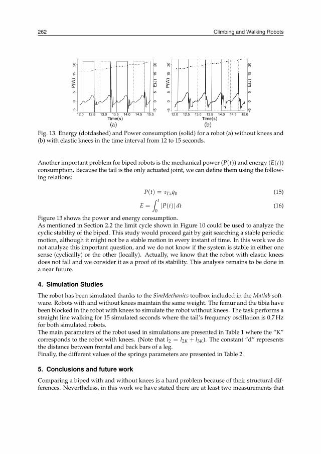
(a) (b)Fig. 13. Energy (dotdashed) and Power consumption (solid) for a robot (a) without knees and(b) with elastic knees in the time interval from 12 to 15 seconds.
Another important problem for biped robots is the mechanical power (P(t)) and energy (E(t))consumption. Because the tail is the only actuated joint, we can define them using the follow-ing relations:
P(t) = τTzq0 (15)
E =∫ t
0|P(t)| dt (16)
Figure 13 shows the power and energy consumption.As mentioned in Section 2.2 the limit cycle shown in Figure 10 could be used to analyze thecyclic stability of the biped. This study would proceed gait by gait searching a stable periodicmotion, although it might not be a stable motion in every instant of time. In this work we donot analyze this important question, and we do not know if the system is stable in either onesense (cyclically) or the other (locally). Actually, we know that the robot with elastic kneesdoes not fall and we consider it as a proof of its stability. This analysis remains to be done ina near future.
4. Simulation Studies
The robot has been simulated thanks to the SimMechanics toolbox included in the Matlab soft-ware. Robots with and without knees maintain the same weight. The femur and the tibia havebeen blocked in the robot with knees to simulate the robot without knees. The task performs astraight line walking for 15 simulated seconds where the tail’s frequency oscillation is 0.7 Hzfor both simulated robots.The main parameters of the robot used in simulations are presented in Table 1 where the “K”corresponds to the robot with knees. (Note that l2 = l2K + l3K). The constant “d” representsthe distance between frontal and back bars of a leg.Finally, the different values of the springs parameters are presented in Table 2.
5. Conclusions and future work
Comparing a biped with and without knees is a hard problem because of their structural dif-ferences. Nevertheless, in this work we have stated there are at least two measurements that
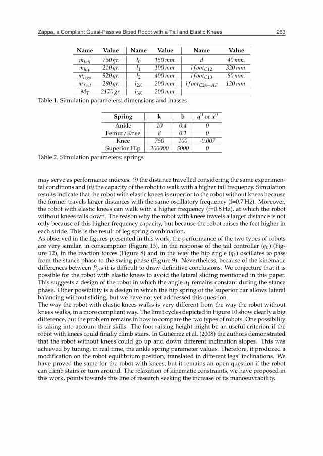
Name Value Name Value Name Valuemtail 760 gr. l0 150 mm. d 40 mm.mhip 210 gr. l1 100 mm. l f ootC12 320 mm.mlegs 920 gr. l2 400 mm. l f ootC13 80 mm.m f eet 280 gr. l2K 200 mm. l f ootC24−AF 120 mm.MT 2170 gr. l3K 200 mm.
Table 1. Simulation parameters: dimensions and masses
Spring k b q0 or x0
Ankle 10 0.4 0Femur/Knee 8 0.1 0
Knee 750 100 -0.007Superior Hip 200000 5000 0
Table 2. Simulation parameters: springs
may serve as performance indexes: (i) the distance travelled considering the same experimen-tal conditions and (ii) the capacity of the robot to walk with a higher tail frequency. Simulationresults indicate that the robot with elastic knees is superior to the robot without knees becausethe former travels larger distances with the same oscillatory frequency (f=0.7 Hz). Moreover,the robot with elastic knees can walk with a higher frequency (f=0.8 Hz), at which the robotwithout knees falls down. The reason why the robot with knees travels a larger distance is notonly because of this higher frequency capacity, but because the robot raises the feet higher ineach stride. This is the result of leg spring combination.As observed in the figures presented in this work, the performance of the two types of robotsare very similar, in consumption (Figure 13), in the response of the tail controller (q0) (Fig-ure 12), in the reaction forces (Figure 8) and in the way the hip angle (q1) oscillates to passfrom the stance phase to the swing phase (Figure 9). Nevertheless, because of the kinematicdifferences between Py,s it is difficult to draw definitive conclusions. We conjecture that it ispossible for the robot with elastic knees to avoid the lateral sliding mentioned in this paper.This suggests a design of the robot in which the angle q1 remains constant during the stancephase. Other possibility is a design in which the hip spring of the superior bar allows lateralbalancing without sliding, but we have not yet addressed this question.The way the robot with elastic knees walks is very different from the way the robot withoutknees walks, in a more compliant way. The limit cycles depicted in Figure 10 show clearly a bigdifference, but the problem remains in how to compare the two types of robots. One possibilityis taking into account their skills. The foot raising height might be an useful criterion if therobot with knees could finally climb stairs. In Gutiérrez et al. (2008) the authors demonstratedthat the robot without knees could go up and down different inclination slopes. This wasachieved by tuning, in real time, the ankle spring parameter values. Therefore, it produced amodification on the robot equilibrium position, translated in different legs’ inclinations. Wehave proved the same for the robot with knees, but it remains an open question if the robotcan climb stairs or turn around. The relaxation of kinematic constraints, we have proposed inthis work, points towards this line of research seeking the increase of its manoeuvrability.
Zappa, a Compliant Quasi-Passive Biped Robot with a Tail and Elastic Knees 263
12.0 12.5 13.0 13.5 14.0 14.5 15.0Time(s)
P(W
)
E(J
)
−50
515
20
−50
515
20
12.0 12.5 13.0 13.5 14.0 14.5 15.0Time(s)
P(W
)
E(J
)
−50
515
20
−50
515
20
(a) (b)Fig. 13. Energy (dotdashed) and Power consumption (solid) for a robot (a) without knees and(b) with elastic knees in the time interval from 12 to 15 seconds.
Another important problem for biped robots is the mechanical power (P(t)) and energy (E(t))consumption. Because the tail is the only actuated joint, we can define them using the follow-ing relations:
P(t) = τTzq0 (15)
E =∫ t
0|P(t)| dt (16)
Figure 13 shows the power and energy consumption.As mentioned in Section 2.2 the limit cycle shown in Figure 10 could be used to analyze thecyclic stability of the biped. This study would proceed gait by gait searching a stable periodicmotion, although it might not be a stable motion in every instant of time. In this work we donot analyze this important question, and we do not know if the system is stable in either onesense (cyclically) or the other (locally). Actually, we know that the robot with elastic kneesdoes not fall and we consider it as a proof of its stability. This analysis remains to be done ina near future.
4. Simulation Studies
The robot has been simulated thanks to the SimMechanics toolbox included in the Matlab soft-ware. Robots with and without knees maintain the same weight. The femur and the tibia havebeen blocked in the robot with knees to simulate the robot without knees. The task performs astraight line walking for 15 simulated seconds where the tail’s frequency oscillation is 0.7 Hzfor both simulated robots.The main parameters of the robot used in simulations are presented in Table 1 where the “K”corresponds to the robot with knees. (Note that l2 = l2K + l3K). The constant “d” representsthe distance between frontal and back bars of a leg.Finally, the different values of the springs parameters are presented in Table 2.
5. Conclusions and future work
Comparing a biped with and without knees is a hard problem because of their structural dif-ferences. Nevertheless, in this work we have stated there are at least two measurements that
Name Value Name Value Name Valuemtail 760 gr. l0 150 mm. d 40 mm.mhip 210 gr. l1 100 mm. l f ootC12 320 mm.mlegs 920 gr. l2 400 mm. l f ootC13 80 mm.m f eet 280 gr. l2K 200 mm. l f ootC24−AF 120 mm.MT 2170 gr. l3K 200 mm.
Table 1. Simulation parameters: dimensions and masses
Spring k b q0 or x0
Ankle 10 0.4 0Femur/Knee 8 0.1 0
Knee 750 100 -0.007Superior Hip 200000 5000 0
Table 2. Simulation parameters: springs
may serve as performance indexes: (i) the distance travelled considering the same experimen-tal conditions and (ii) the capacity of the robot to walk with a higher tail frequency. Simulationresults indicate that the robot with elastic knees is superior to the robot without knees becausethe former travels larger distances with the same oscillatory frequency (f=0.7 Hz). Moreover,the robot with elastic knees can walk with a higher frequency (f=0.8 Hz), at which the robotwithout knees falls down. The reason why the robot with knees travels a larger distance is notonly because of this higher frequency capacity, but because the robot raises the feet higher ineach stride. This is the result of leg spring combination.As observed in the figures presented in this work, the performance of the two types of robotsare very similar, in consumption (Figure 13), in the response of the tail controller (q0) (Fig-ure 12), in the reaction forces (Figure 8) and in the way the hip angle (q1) oscillates to passfrom the stance phase to the swing phase (Figure 9). Nevertheless, because of the kinematicdifferences between Py,s it is difficult to draw definitive conclusions. We conjecture that it ispossible for the robot with elastic knees to avoid the lateral sliding mentioned in this paper.This suggests a design of the robot in which the angle q1 remains constant during the stancephase. Other possibility is a design in which the hip spring of the superior bar allows lateralbalancing without sliding, but we have not yet addressed this question.The way the robot with elastic knees walks is very different from the way the robot withoutknees walks, in a more compliant way. The limit cycles depicted in Figure 10 show clearly a bigdifference, but the problem remains in how to compare the two types of robots. One possibilityis taking into account their skills. The foot raising height might be an useful criterion if therobot with knees could finally climb stairs. In Gutiérrez et al. (2008) the authors demonstratedthat the robot without knees could go up and down different inclination slopes. This wasachieved by tuning, in real time, the ankle spring parameter values. Therefore, it produced amodification on the robot equilibrium position, translated in different legs’ inclinations. Wehave proved the same for the robot with knees, but it remains an open question if the robotcan climb stairs or turn around. The relaxation of kinematic constraints, we have proposed inthis work, points towards this line of research seeking the increase of its manoeuvrability.

Climbing and Walking Robots264
6. References
Alexander, R. M. (2005). Walking made simple, Science Magazine 308(5718): 58–59.Berenguer, F. J. & Monasterio-Huelin, F. (2006). Easy design and construction of a biped walk-
ing mechanism with low power consumption, Proc. of the 9th Int. Conf. Climbing andWalking Robots CLAWAR’06, Springer-Verlag, Berlin, Germany, pp. 96–103.
Berenguer, F. J. & Monasterio-Huelin, F. (2007a). Stability and smoothness improvements foran underactuated biped with a tail, Proc. of the 2007 IEEE Symp. on Industrial Electron-ics, IEEE Press, Piscataway, NJ, pp. 2083–2088.
Berenguer, F. J. & Monasterio-Huelin, F. (2007b). Trajectory planning using oscillatory chirpfunctions applied to bipedal locomotion, Proc. of the 4th Int. Conf. on Informatics inControl, Automation and Robotics, IEEE Press, Piscataway, NJ, pp. 70–75.
Berenguer, F. J. & Monasterio-Huelin, F. (2008). Zappa, a quasi-passive biped walking robotwith a tail. modeling, behavior and kinematic estimation using accelerometers, IEEETransactions on Industrial Electronics 55(9): 3281–3289.
Boeing, A. & Bräunl, T. (2004). Evolution of locomotion controllers for legged robot, in T. et al.(ed.), Robotic Welding, Intelligence and Automation, Vol. 299 of Lecture Notes in Controland Information Sciences (LNCIS), Springer-Verlag, Berlin, Germany, pp. 228–240.
Collins, S. H. & Ruina, A. (2005). A bipedal walking robot with efficient and human-like gait,Proc. of the 2005 IEEE Int. Conf. on Robotics and Automation, IEEE Press, Piscataway,NJ, pp. 1983–1988.
Fumiya, I., Minekawa, Y., Rummel, J. & Seyfarth, A. (2009). Toward a humanlike biped robotwith compliant legs, Robotics and Automation Systems 57(2): 139–144.
Fumiya, I. & Pfeifer, R. (2006). Sensing through body dynamics, Robotics and AutonomousSystems 54(8): 631–640.
Geyer, H. & Seyfarth, A. (2006). Walking and running dynamics explained by compliantlegs: Consequences, general insights, and future directions, Journal of Biomechanics39(1): 361.
Gutiérrez, A., Berenguer, F. J. & Monasterio-Huelin, F. (2008). Evolution of neuro-controllersfor trajectory planning applied to a bipedal walking robot with a tail, in A. Lazinika(ed.), New Developments in Robotics, Automation and Control, I-Tech Education andPublishing, Vienna, Austria.
Ham, R. V., Vanderborght, B., Damme, M. V., Verrelst, B. & D.Lefeber (2007). Maccepa,the mechanically adjustable compliance and controllable equilibrium position actu-ator: Design and implementation in a biped robot, Robotics and Autonomous Systems55(10): 761–768.
Hobbelen, D. G. E. & Wisse, M. (2007). Limit cycle walking, in M. Hackel (ed.), HumanoidRobots, Human-like Machines, I-Tech Education and Publishing, Vienna, Austria.
Hurmuzlu, Y., Génot, F. & Brogliato, B. (2004). Modeling, stability and control of biped robotsA general framework, Automatica 40(10): 1647–1664.
Kuo, A. (2007). The six determinants of gait and the inverted pendulum analogy: A dynamicwalking perspective, Human Movement Science 26(4): 617–656.
McGeer, T. (1990). Passive dynamic walking, Int. Journal of Robotics Research 9(2): 62–82.McMahon, T. (1984). Muscles, Reflexes, and Locomotion, Princeton Press, Princeton, NJ.Pfeifer, R. & Bongard, J. C. (2007). How the Body Shapes the Way We Think: A New View of
Intelligence (Bradford Books), The MIT Press, Cambridge, MA.Vukobratovic, M., Borovac, B., Surla, D. & Stokic, D. (1990). Biped Locomotion: Dynamics,
Stability, Control and Application, Springer-Verlag, Berlin, Germany.
View publication statsView publication stats