Z-WAVE GLYDEA MODULE - USA SomfyPro · 1 Z-WAVE GLYDEA MODULE DESCRIPTION The Somfy Z-Wave Glydea...
3
1 Z-WAVE GLYDEA MODULE DESCRIPTION The Somfy Z-Wave Glydea (ZGM) is a Z-Wave routing device that resides as a node within a designated Z-Wave control network. It receives Z-Wave transmissions and converts them to motor control commands for operating Somfy’s Glydea 35 and Glydea 60E drapery motors. Part No: 1870228 Z-Wave Glydea Module INSTALLATION In order for the Z-Wave Glydea Module to become fully operational, the Glydea motor must first be verified to be functional with its drapery. Please refer to the Glydea Motor installation manual for more information. The Z-Wave Glydea Module (ZGM) is designed to be mounted in the bottom cavity of the Glydea drapery motor. To install the ZGM, ensure that the power cord is disconnected from the AC outlet and remove the plastic cover on the bottom of the motor (see Figure 1). Remove the protective tape covering the Velcro on the bottom of the ZGM, and install as shown in Figure 2. Insert the 6-pin modular connector into the modular jack to complete the installation. Do not install the plastic cover at this time. Figure 1. Plastic Cover Figure 2. ZGM Installed
-
Upload
phungthien -
Category
Documents
-
view
233 -
download
0
Transcript of Z-WAVE GLYDEA MODULE - USA SomfyPro · 1 Z-WAVE GLYDEA MODULE DESCRIPTION The Somfy Z-Wave Glydea...
1
Z-WAVE GLYDEA MODULE
DESCRIPTION The Somfy Z-Wave Glydea (ZGM) is a Z-Wave routing device that resides as a node within a designated Z-Wave control network. It receives Z-Wave transmissions and converts them to motor control commands for operating Somfy’s Glydea 35 and Glydea 60E drapery motors.
Part No: 1870228
Z-Wave Glydea Module INSTALLATION In order for the Z-Wave Glydea Module to become fully operational, the Glydea motor must first be
verified to be functional with its drapery. Please refer to the Glydea Motor installation manual for more information.
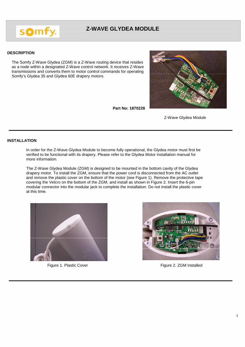
The Z-Wave Glydea Module (ZGM) is designed to be mounted in the bottom cavity of the Glydea drapery motor. To install the ZGM, ensure that the power cord is disconnected from the AC outlet and remove the plastic cover on the bottom of the motor (see Figure 1). Remove the protective tape covering the Velcro on the bottom of the ZGM, and install as shown in Figure 2. Insert the 6-pin
modular connector into the modular jack to complete the installation. Do not install the plastic cover at this time.
Figure 1. Plastic Cover Figure 2. ZGM Installed

2
NETWORK SETUP
Setup Button Including the ZGM into a Network
1. Plug the power cord into a standard AC outlet, and verify that the Inclusion LED turns on for approx. five (5) seconds, then goes off. If the Inclusion LED does not turn off, perform a factory reset as outlined in the FACTORY RESET section. When the LED turns off, press and release the Setup Button several times to verify motor movement.
2. Select the Inclusion command on your Z-Wave Primary Controller.
3. Press the Setup Button to include the ZGM in the network. Verify that
the Inclusion LED stays on when the module is included in the network.
4. Verify that the ZGM is operational from your primary controller, and Inclusion LED install the plastic cover on the bottom of the motor.
Excluding the ZGM from a Network
1. Remove the plastic cover from the bottom of the motor. 2. Select the exclusion command on your Z-Wave Primary Controller. 3. Press the Setup button to exclude the ZGM from the network.
Verify that the Inclusion LED turns off.
MANUAL OPERATION The Setup Button can be used to manually operate the motor at any time as follows:
1. With the motor at rest, pressing & releasing the Setup Button will send the motor to its OPEN or CLOSED limit.
With the motor at rest, pressing & holding the Setup Button will send the motor in the OPEN or CLOSED direction, then STOP in position when the button is released. 2. While the motor is moving, press & release the Setup Button to reverse direction to its opposite limit.
The Setup Button may also be pressed & held, then released at the desired position to stop the motor. FACTORY RESET The ZGM can be reset to factory conditions while the Glydea motor is either installed or removed from its track.
1. Remove the plastic cover from the bottom of the motor.
2. Remove the 6-pin modular connector from the modular jack, and remove the ZGM from the bottom cavity of the Glydea motor.

3
FACTORY RESET CON’T.
3. Ensure that the power cord is plugged into a standard AC outlet. Then, press & hold the Setup Button while plugging the 6-pin modular connector into the modular jack. Do not release the Setup Button.
4. The Inclusion LED will flash several times then, turn off. When the Inclusion LED turns off, release the
Setup Button. The ZGM is now reset. Z-WAVE CERTIFICATION Z-Wave Certification of the Z-Wave Glydea Module is pending.
Z-WAVE GLYDEA MODULE ELECTRICAL SPECIFICATION
Voltage Input: +5VDC supplied by the Glydea Motor Power Consumption: 30 mA max. @ +5VDC.
ORDERING INFORMATION
Description Part Nu mber
Z-Wave Glydea Module 1870228
Glydea35 Motor 1001536
Glydea60E Motor 1001538
CONTACT SOMFY Somfy Technical Support USA
800-647-6639 Monday through Friday 8:00AM – 8:00PM EST
Somfy Customer Service Email USA
North East Region [email protected]
Southeast Region [email protected]
Central Regions [email protected]
West Coast Region [email protected]