Yung P. Lee (ASAP 2001, March 14, 2001) Science Applications International Corporation 1710 SAIC...
23
Yung P. Lee (ASAP 2001, March 14, 2001) Science Applications International Corporation 1710 SAIC Drive McLean, VA 22102 [email protected] S pace-T ime A daptive M atched-field P rocessing (STAMP)
-
date post
21-Dec-2015 -
Category
Documents
-
view
213 -
download
0
Transcript of Yung P. Lee (ASAP 2001, March 14, 2001) Science Applications International Corporation 1710 SAIC...
Yung P. Lee(ASAP 2001, March 14, 2001)
Science Applications International Corporation
1710 SAIC Drive
McLean, VA 22102
Space-Time Adaptive Matched-field Processing (STAMP)

1
0
/)sin(2 Array Line Linear)()(N
n
cnfdiendxB
dtetxfX fti 2)()(
Fourier Transform Spectral (Frequency) Content
Sonar Signal Processing Background
1
0
2)()()(N
n
tnfietnxtxFFTfX
Spatial Beamforming Direction (Angle) of Arrival (DOA)
1
0
)()()(N
n
in exB rkr

Matched Field Processing
Matched Field Processing 3D (Range,depth, bearing) Localization*1
0 1
),(),(),,(
N
n
ikM
msnmnnsss
nsmezzazxzrB rrr
pct
p 222
2
iwtikM
m sm
smmss ee
k
zzazzp sm rr
rrrr
1
)()(2),;,(
0])([ 2202
2
mmm kzk
dz
d
rrrr
smikM
msmss ezzazzp
1
),(),;,(
Matched Field Tomography Modal Information Environmental Info.
mmssssss akzrBzr , w.r.t.),,(max ;,, Given


Synthetic Aperture Matched Field Processing
1
0
*
1
),()(),,(N
n
ikM
msnmsnsss
nsmezzatnvrxvzrB rr
source at 76 m towed at 2.5 m/s from 9.18 km


Space Time Matched Field Processing
Matched Field Processing
1
0
* ),;,(),(),,(N
nssnnnnsss zzpzxzrB rrr
Space Time Matched Field Processing
1
0
* ),;,(),(),,(N
nssnnnnsss zztnptnzxzrB rvrvr
Localization & Doppler (velocity) Discrimination
1
0
* ),;,(),(),,,(N
nssnntnntssss zztnptnzxvzrB rvrvr
Phone-Doppler Space
Beam-Doppler Space
),;,(),(),,,( *ssnntnntssss zztnptnzxvzrB
nnrvrvr rr

BACKGROUND/OBJECTIVE
• Space-Time Adaptive Processing (STAP) coherently combines signals from the elements of an array and the multiple snapshots of signals, to achieve large spatial/temporal signal gain, to suppress interference, and to provide target detection in azimuth and velocity.
• Matched-field processing (MFP) coherently combines complex multi-path arrivals, to recover signal multi-path spreading loss and to provide range/depth localization.
• STAMP combines STAP and MFP to improve detection and localization performance for the mobile multi-line-towed-array sonar systems.

Azi
mu
th (
deg
)
0
90
180
Doppler (Hz)-fmax 0 fmax
Doppler (Hz)-fmax 0 fmax
Target
Target
Clutter (Bottom Bounce)
Clu
tter
(Bot
tom
Rev
erbe
ratio
n)
JammerJammer(own-ship)
FW
DA
FT
STAP
Detect the dot Null the Jammer and the slanted clutter
STAMP
Detect/combine/class/localize the dots Null the Jammer and the clutter
PassiveForward-sector processing

Cm ,fm
fm=f0*v/cm
Higher Mode (Path,Angle), Larger cm
Larger cm, Higher Angle (off horizontal), Smaller Doppler
C1 ,f1
Multi-path Doppler/Angle Spread

OUTLINE
• STAMP Processing
• Simulation scenario for forward-sector processing
• Simulation Results

Br(f0)
Beam-space replica
(Selected Beams and Dopplers)
Phone 1Line 1 x11(t)
Phone nLine 1 xn1(t)
Doppler Processing
X1(f)
Conventional Beamforming
B1(f)B(f)
Beam-Space Vector
(selected Beamsand Dopplers)
WB/NBAdaptive
MFP
Doppler Processing
Xr (f)
Conventional Beamforming
Br(f)
Phone 1Line k x1k(t)
Phone nLine k xnk(t)
Doppler Processing
Xk(f)
Conventional Beamforming
Bk(f)
Propagation Code to generate
Replicaxr(t)
OutputAmbiguity
SurfaceR,Zv
Space-Time Adaptive Matched-field Processing (STAMP)
SearchR,Zv
Forming Covariance
Matrix
R = < B(f) B+(f)>f
&Decomposition
B(f) = [B1(f)…. B1(f+mf),…….., Bk(f)…. Bk(f+mf)]
Bk(f) = [bk(f,1)…… bk(f,l)]
AELEnviron.
*Plane-wave ~ STAP

Adaptive Processing
)1(
w.r.t.Minimize
WWRWW
W
S
ARA
ARW
1
1
ARA 11
S
Adaptive Weight Vector
Adaptive Output
**A is the steering vector**R is the measured covariance matrix
ttt )()( xxR
High resolutionSidelobe suppressionSubject to mismatch – Robust Methods(widen the peak)

Wideband-Narrowband (WB/NB) Feedback-Loop White-Noise-Constrained (FLWNC)
Adaptive Processing
Br(f0)
Beam-space replica
(Selected Beams and Dopplers)
Covariance Matrix
R = < B(f) B+(f)>f
&Decomposition
VVλ nn
nnR
BRB
BRBBR
r1
r
r1
r
r1
1S
w
δw 2
1
2
BRB
BRRB
BRBBR
r 1
r
r 11
r
r 1
r
r 1
RS
w
2
δw 2
2
2
Adaptiveweight
W
VVλ
R nn
nn
1- 1
yes= s
yes= s
no
no
WB/NBProcessingS(f)=W+B(f)
* B(f) is “narrowband” (single f) R and W are “broadband” (averaged over band of f)
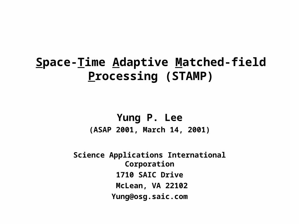
Simulation Geometry (F=200 Hz) target(NB)=120 dB, own-ship(BB)=120 dB, bottom bounce(BB)=115 dB
WNL=70 dB, 0.1 random phase error
3 kts
3 kts
towed array
own-ship noise
bottom bounce
10 km
188 m
Single-Line
4-Line-Sequential
4-Line-Vertical
No environmental mismatch

Single-Line BTRs of Each Signal ComponentForward Endfire at 0o
Own-Ship Noise Bottom Bounce
Target
__ Own-ship__ Bottom Bounce__ Target
Responses at 10o Azimuth

Single-Line Doppler/Azimuth Responses integration time =256-sec, Target Range=10 km, Forward Endfire at 0o
Own-Ship Noise Bottom Bounce
Target
__ Own-ship__ Bottom Bounce__ Target
Selected beams (0o-30o) &
Dopplers (6 bins for 6-kt search)
Responses at 10o Azimuth

Single-Line Beam/Cell Spectrograms
Conventional Plane-Wave (10o) Adaptive Plane-Wave (10o)
Adaptive MFP (target track)
__ Adaptive PW__ Adaptive MFP
Peak Level over Dopplers

Adaptive Beam/Cell Spectrograms
Adaptive Plane-Wave (10o) Single Vertical Adaptive MFP
4_Line_Vertical Adaptive MFP
__ PW__ Single Line MFP__ 4_Line_Vert MFP
Peak Level over Dopplers
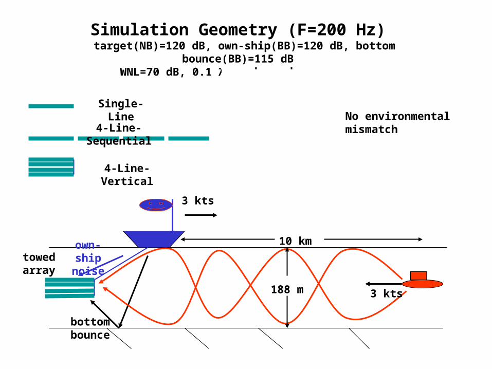
Single Line, Conventional MFP
4_Line_Sequential, Adaptive MFP 4_Line_Vertical, Adaptive MFP
Single Line, Adaptive MFP
Array Size Dependence of MFP Range Tracking search at target depth and target speed

Depth Discrimination of Adaptive MFP Range Tracking 4_Line_Vertical Array search at target speed
Depth=10 m
Depth=180 mDepth=90 m
Depth=60 m

Speed= 3 m/s
Speed= -3 m/sSpeed= -1 m/s
Speed= 1 m/s
Speed Discrimination of Adaptive MFP Range Tracking 4_Line_Vertical Array search at target depth
SUMMARY
• STAMP processing that combines STAP and MFP has been developed.
• Simulations show that STAMP coherently combines signal multi-path spread in azimuth and Doppler and greatly enhances target detection as well as providing target range and depth classification and localization.