YuanDong SkyHawk Engine Parts Kit - Grubee Inc. Instructio… · · 2012-08-03YuanDong SkyHawk...
29
1 PLEASE READ THESE INSTRUCTIONS BEFORE INSTALLATION WEB SITE REFERENCE: www.grubeeinc.com Instructions Copy Righted: Rev. Dec 1, 2011 YuanDong SkyHawk Engine Parts Kit: GT2A > 1.4Kw 48cc / 40mm x 38mm bore and stroke: Square Head. 203 crankshaft brgs. GT2B > 1.4Kw 48cc / 40mm x 38mm bore and stroke: Round Head. 202 crankshaft brgs. GT5 > 1.6Kw 66cc / 47mm x 38mm bore and stroke: Square Head; 202 crankshaft brgs. Kit Box Contents: Due to many kit options and rules of different countries contents may vary: 2 cycle crankcase scavenging gas/oil mix engine with 2 point fixed mounting; Exhaust muffler; Tear Drop 2.5L Fuel Tank plated inside; Drive chain; Chain guard; Sprocket with 9 hole mounting hardware for 36 spoke wheel; Chain idler; Push button clutch lever, Carburetor; CD Ignition, Twist throttle with kill switch: Control cables; Tool kit with extra service parts; ( To ensure reliable engine performance: DO NOT use other than original SkyHawk replacement parts.) Note: Mechanical aptitude and experience is required to perform this installation. Many “Do It Yourself” mechanics will find this project rewarding. A love of small engines is the only requirement for this project. However, installation is sometimes best done by a professional auto or motorcycle mechanic. Frame size should be 28mm to 30mm dia. with 70 degree included V angle. For sufficient engine clearance select a bike with a seat tube length of at least 12 ½ inches measured between bottom of top tube and top of pedal sprocket tube. A rewarding joy and challenge is found in designing a custom installation of your own. Remember, a quality installation is paramount to safe usage and long term satisfaction. You may find many other uses for this engine kit such as for stationary machine power or 4 wheeled off road riding machines. Have fun and good luck on your motorized project. STEP #1 Mounting the Engine: 1. The engine mounts in a “Vee” frame. It is best to make sure all 4 engine studs are securely bottomed out in the engine before mounting. Use a Jam nut procedure to tighten. 2. Consider using Masking or Duct Tape on the front down-tube & seat tube of your bicycle to protect the paint finish while test fitting the engine to your donor bike. If the distance between the two frame tubes exceeds the engine mounting span then additional spacers or welded brackets may be required. Mount the engine to the seat tube first and then fit to the front tube. If frame tube fit is smaller than engine clamp dia. use strip shims to fit. See examples of Ft Mt installation on a big downtube bike frame..
-
Upload
duongthien -
Category
Documents
-
view
214 -
download
1
Transcript of YuanDong SkyHawk Engine Parts Kit - Grubee Inc. Instructio… · · 2012-08-03YuanDong SkyHawk...

1
PLEASE READ THESE INSTRUCTIONS BEFORE INSTALLATION
WEB SITE REFERENCE: www.grubeeinc.com Instructions Copy Righted: Rev. Dec 1, 2011
YuanDong SkyHawk Engine Parts Kit:
GT2A > 1.4Kw 48cc / 40mm x 38mm bore and stroke: Square Head. 203 crankshaft brgs.
GT2B > 1.4Kw 48cc / 40mm x 38mm bore and stroke: Round Head. 202 crankshaft brgs.
GT5 > 1.6Kw 66cc / 47mm x 38mm bore and stroke: Square Head; 202 crankshaft brgs.
Kit Box Contents:
Due to many kit options and rules of different countries contents may vary:
2 cycle crankcase scavenging gas/oil mix engine with 2 point fixed mounting; Exhaust muffler; Tear Drop
2.5L Fuel Tank plated inside; Drive chain; Chain guard; Sprocket with 9 hole mounting hardware for 36
spoke wheel; Chain idler; Push button clutch lever, Carburetor; CD Ignition, Twist throttle with kill
switch: Control cables; Tool kit with extra service parts;
( To ensure reliable engine performance: DO NOT use other than original SkyHawk replacement parts.)
Note: Mechanical aptitude and experience is required to perform this installation. Many “Do It Yourself”
mechanics will find this project rewarding. A love of small engines is the only requirement for this project.
However, installation is sometimes best done by a professional auto or motorcycle mechanic. Frame size
should be 28mm to 30mm dia. with 70 degree included V angle. For sufficient engine clearance select a bike
with a seat tube length of at least 12 ½ inches measured between bottom of top tube and top of pedal
sprocket tube. A rewarding joy and challenge is found in designing a custom installation of your own.
Remember, a quality installation is paramount to safe usage and long term satisfaction. You may find many
other uses for this engine kit such as for stationary machine power or 4 wheeled off road riding machines.
Have fun and good luck on your motorized project.
STEP #1 Mounting the Engine: 1. The engine mounts in a “Vee” frame. It is best to make sure all 4 engine studs are securely bottomed out
in the engine before mounting. Use a Jam nut procedure to tighten.
2. Consider using Masking or Duct Tape on the front down-tube & seat tube of your bicycle to protect the
paint finish while test fitting the engine to your donor bike. If the distance between the two frame tubes
exceeds the engine mounting span then additional spacers or welded brackets may be required. Mount
the engine to the seat tube first and then fit to the front tube. If frame tube fit is smaller than engine
clamp dia. use strip shims to fit. See examples of Ft Mt installation on a big downtube bike frame..
2
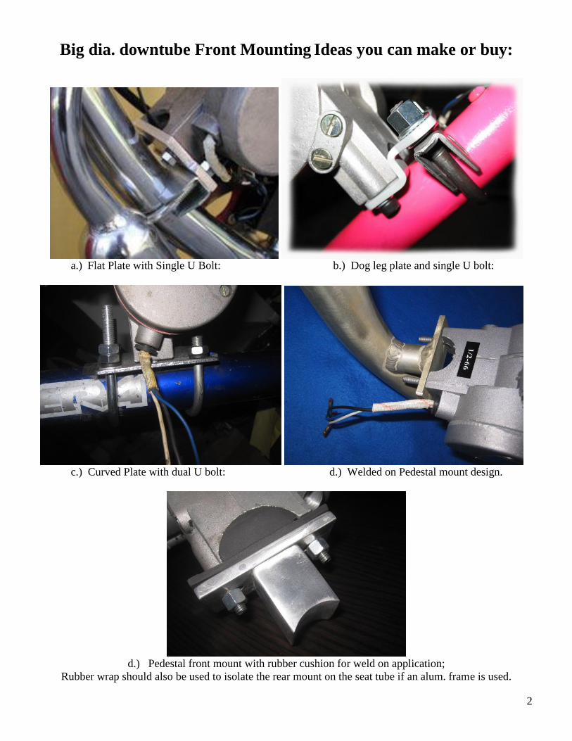
Big dia. downtube Front Mounting Ideas you can make or buy:
a.) Flat Plate with Single U Bolt: b.) Dog leg plate and single U bolt:
c.) Curved Plate with dual U bolt: d.) Welded on Pedestal mount design.
d.) Pedestal front mount with rubber cushion for weld on application;
Rubber wrap should also be used to isolate the rear mount on the seat tube if an alum. frame is used.

3
Figure 1.
Bike with wide frame or big down tube: Use ¼” thick 1-1/8” x 2-1/2” steel plate with one hole in the
center for a bolt to go through a drilled hole in tube frame and two holes for cap screws to go into
engine block. Additional spacers maybe required depending on the donor bike.
Figure # 1
3. If the rear frame tube from the seat down to the pedal sprocket is too small to fit the rear engine mount, a
rubber shim can be made from an old bicycle rubber inner tube. This also helps reduce engine vibration.
Engine needs to have the carburetor set in a level position. Too much engine tilt can cause chain to hit
the drive cover and engine to not run correctly. It is best to have the drive chain to rear wheel
sprocket be as horizontal as possible with no more than 15 degrees max engine tilt. After the
desired engine location is determined mount the engine to frame. Appling LocTite thread lock is
recommended to avoid loosening due to vibration. Note: All threads are metric.
Chain Wheel Sprocket Installation: The Drive Chain Sprocket has a 36.9 mm dia. center hole and mounts on axel hub on the left side of the
rear wheel against the spokes dish side in. The sprocket must fit over the hub in a perpendicular plane with
the axle. This insures that your rear chain sprocket spins true with the rear bike wheel. *NOTE: On some
older bike axle hubs like on coaster brake models it may be required to slightly enlarge the sprocket center
hole to obtain a flush, and concentric fit next to the spokes. This is best done on a engine lathe by a
professional machinist.. . It is also recommended that the rear wheel be re-spoked to 12 ga. spoke wires to
insure long life. Most any Bike shop can do this operation for you. Applying thread adhesive and equal
tightening of the sprocket bolts. This keeps the chain sprocket true with axle and free from wobble while
spinning. With bike upside down spin wheel and check sprocket for wobble. The chain can jump off the
sprocket if the sprocket installation is done incorrectly
1. Place rubber isolator next to spokes and locate sprocket on axel hub with curved side next to spokes,
shinny side in. Cut the rubber isolator ring between holes in order to fit INSIDE the spokes and around
the axle. Install the 5 split steel retainer plates 3 in and 2 out next to the rubber isolator and insert 9 bolts.
2. Secure with 9 bolts compressing the chain sprocket to the spokes. Note: Rubber isolators may be needed
on both sides or on one side of sprocket for chain alignment, install as required:
3. The Chain Sprocket on the Wheel must align within 1/2 cm to the Chain Sprocket on the Engine.
4
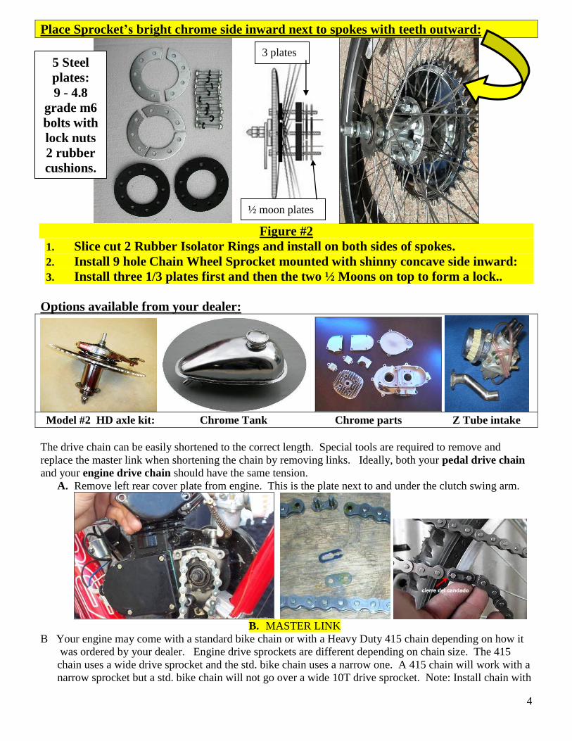
Place Sprocket’s bright chrome side inward next to spokes with teeth outward:
Figure #2
1. Slice cut 2 Rubber Isolator Rings and install on both sides of spokes.
2. Install 9 hole Chain Wheel Sprocket mounted with shinny concave side inward:
3. Install three 1/3 plates first and then the two ½ Moons on top to form a lock..
Options available from your dealer:
Model #2 HD axle kit: Chrome Tank Chrome parts Z Tube intake
The drive chain can be easily shortened to the correct length. Special tools are required to remove and
replace the master link when shortening the chain by removing links. Ideally, both your pedal drive chain
and your engine drive chain should have the same tension.
A. Remove left rear cover plate from engine. This is the plate next to and under the clutch swing arm.
B. MASTER LINK
B Your engine may come with a standard bike chain or with a Heavy Duty 415 chain depending on how it
was ordered by your dealer. Engine drive sprockets are different depending on chain size. The 415
chain uses a wide drive sprocket and the std. bike chain uses a narrow one. A 415 chain will work with a
narrow sprocket but a std. bike chain will not go over a wide 10T drive sprocket. Note: Install chain with
5 Steel
plates:
9 - 4.8
grade m6
bolts with
lock nuts
2 rubber
cushions.
3 plates
½ moon plates

5
master link clip on outboard side of the primary drive sprocket teeth. ( Note: wide tires larger than 2.125
may rub on a wide 415HD chain: )
C. Use supplied spark-plug wrench to turn engine crankshaft sprocket to feed chain around it. Do not pry
sprocket with a screwdriver or similar object.
D. Fit chain, measure and remove excess links to assure proper length. Be sure master link connection rides
on the inboard side of the primary drive sprocket or interference of link and sprocket can occur. Proper
chain length is when top chain has ¼ inch to ½” deflection with the bottom side of the chain loop tight.
E. Chain tension adjustments can be made by pulling rear wheel back if frame has straight slot wheel drop out.
If both chains can be adjusted equally then installing chain idler on the wheel strut may not be necessary.
At installer’s discretion the chain idler can be installed on either the pedal chain or engine drive chain.
F. Install supplied chain safety guard by attaching to engine and wheel axle struts.
Ignition Coil and Engine Kill Switch installation
A) Mount CD ignition coil on bike frame, close enough to attach coil wire to spark plug. Mount as far away
from exhaust pipe as possible to avoid heat damage to semiconductors in CDI module.
B) Attach CD ignition coil wires to same identical color coded wires coming from engine.
C) Install Engine Kill Switch Wire on throttle to white wire coming from engine. Install the other wire with
eyelet to a good frame ground not on paint. This will ground ignition and stop the engine when the kill
button switch is activated.
D) Route all wires away from engine exhaust heat. Secure wires with a plastic tie straps.
*!WARNING! Operation of engine without stop or kill switch installed could result in personal injury
if an emergency stop is required! The only alternate non recommended way of killing the engine is by
releasing the clutch lever with bike brakes on and engine at slowest idle.
Catalytic muffler; Throttle with kill swt. CDI ign. CNS YD Carb. Speed Carb.
Push button Clutch lever: Optional Dual lever Clutch & Brake Clutch cable end locks in lever handle.
Clutch cable installation and adjustment:
A) Install clutch lever to left side of handlebar and attach cable end barrel into lever slot hole.
B) Squirt oil down the cable sleeve: Route clutch cable through the ball-mount on motor with the big spring
around the cable jacket and ahead of the ball mount. The big spring serves as a cable heat shield.
2010 2008/2009

6
C) Insert cable wire through small spring and route through clutch arm and attach brass cable-end and
screw. Adjust cable tension to allow very slight play in arm. Handlebar clutch lever must be in the
released or outward position to complete this operation.
D) Activate lever a few times, and check clutch arm for slight free play: About 1/16” engine clutch arm
free play is required with the handle bar lever in the released in what is called clutch engaged
position or the engine will fail to start if cable is too loose or if too tight. Re-adjust as required. E) Basics of clutch operation: The handlebar lever pulls the cable that moves the engine clutch arm. In turn
the clutch arm pushes a rod through the motor that pushes the clutch plate out. ( similar to a car clutch.)
Releasing the handle bar lever engages the clutch and provides engine torque to the drive chain or to start
the engine. The clutch friction allows engine to start, and also transmits engine torque to the drive chain.
When the bike is in the pedal mode the handle bar clutch lever is locked inward in the catch notch. The
bike then operates in default as it would without any engine. Periodic clutch adjustment is necessary to
maintain efficient operation *NOTE: Cut off excess cable from clutch arm, before operation, to avoid
possible interference with pedals, chain, your legs, etc. See Figure #4.
Clutch arm: Clutch cable Note brass screw lock at the end;
1/16” free play:
Figure #4 Additional cable adjustment can be made at mid joint if your kit has this.
NOTE: If Clutch cable is not adjusted correctly the engine will not start. Check for 1/16 “ clutch cable
arm free play with handle bar lever released.
Carburetor and Throttle Installation
OPTIONAL NEW STYLE THROTTLE
with kill switch:
Kill switch; one wire goes to white wire
from engine and the other to frame grd.
Drill small hole in handle bar for pin lock.

7
Install CDI module on down tube as far away from engine heat as possible.
First install Blue & Black wires from engine magneto to same color CDI wires. Warning:
Do not hook up backwards or damage will occur to the CDI. Next install the throttle
handle kill switch wires into the 2 remaining open holes of the 2 CDI wire terminals. Push
the clear rubber protectors over the 2 connections and tape with black electrical tape. The
remaining white wire from the engine is not needed unless you want to run a small wattage
6V headlight but it’s not recommended as it will rob engine ignition power requirements so is
really best to tape this wire up securely or just snip it off at the engine exit plug. Use a heat
shrink tube over the wire sheathing to keep water out of the magneto box.
Blk. wire from engine to Blk. of CDI
Blue wire from engine to Blue of CDI
Two kill switch wires can go to either of the remaining 2
empty holes of the CDI terminals: Color code not important.
For CDI Color code is very important:
Like to Like.
NOTE: Even though an extra cost Black PC is
an optional engine finish it is not recommended.
It only looks good for a while and does nothing
for engine performance. It can actually hinder
efficient air cooling of aluminum cylinder fins.
8
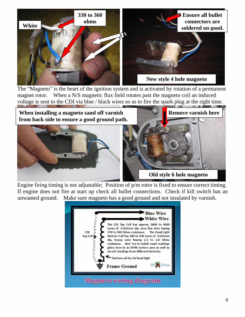
The “Magneto” is the heart of the ignition system and is activated by rotation of a permanent
magnet rotor. When a N/S magnetic flux field rotates past the magneto coil an induced
voltage is sent to the CDI via blue / black wires so as to fire the spark plug at the right time.
Engine firing timing is not adjustable; Position of p/m rotor is fixed to ensure correct timing.
If engine does not fire at start up check all bullet connections. Check if kill switch has an
unwanted ground. Make sure magneto has a good ground and not insulated by varnish.
330 to 360
ohms
New style 4 hole magneto
When installing a magneto sand off varnish
from back side to ensure a good ground path.
White
Remove varnish here
Old style 6 hole magneto
Ensure all bullet
connectors are
soldered on good.

9

10

11
#1. NT Carb. #2. SPEED carb #3. YD CNS Carb #4. YuanDong Skyhawk
( NOTE: Engine Kits to USA have a Fuel Line EPA approved for permeation rating )
SkyHawk Carburetor Family. ( 4 Different kinds)

12
Procedure for attaching throttle cable to NT & SPEED carburetor slide valve:
The small stop on the cable wire end slides through the long groove on the slide valve. Early slide
valves were made of brass and later ones are made of black plastic. Beware that there are 2 sizes of black
plastic slide valves. Normally; 14.95mm dia. for 66cc and 14.42mm dia. for 48cc are used but slide valve
must match the appropriate carb. housing hole dia. to work. Jet sizes are available from 0.80 to 0.65mm.
Note: Speed Carburetors have fuel
shut off valve and bowl drain petcock;
Also these carbs. have larger 14.95mm
throttle slides and outlet openings
than found in X brand carbs. The
square red or the square black AC is
interchangeable with small white or
black round versions.
.
Be sure to check carb. air cleaner attach screws for tightness before installing engine:
Air cleaner screw coming loose and entering engine is not covered by warranty;
A.) Note component positions in pictures; Needle clip is factory set in second slot: If a more rich gas
mixture is required you can move the jet pin “pac man” clip to the next lower position notch.)
When the throttle is twisted a spring inside the cylinder valve is compressed and the slide valve is raised to
give more air & fuel to the engine. For this to work properly the throttle must twist freely on the handle bar
in both directions prior to the cable being installed.
B.) Install twist grip throttle on right side of handlebar end. On some handle bars it may be necessary to
ream out the handle ID to fit the bar so that the throttle will twist freely. It never hurts to add a few drops of
light wt. oil to let trickle down the cable inside the full length of sheathing.
C.) After installing cable inside the carburetor you are ready to mount it on engine intake tube and tighten
clamp screw. Mount the engine so carburetor sets as level as possible.

13
#3. YD EPA Carb Skyhawk engines sent to USA in 2010 & 2011 have a CNS YD EPA Carb. that
attaches to a long Z intake tube. Be sure the fuel line does not touch the hot engine. Make sure the 2
vent tubes are not left open without plastic lines attached as dirt will enter straight down into the bowl.
Only the Small Hole 1.5” wide paper cone air cleaner can be used. The air adjustment screw is sealed
per EPA requirements and has external cable choke control. Turning idle screw CW increases RPM.
#4. YuanDong SkyHawk Carb. YuanDong SkyHawk carb. is a redesigned and improved version of
the above CNS YD carb and has adjustable air and idle adjustment with vertical fuel inlet. This carb
comes with a 0.068 mm dia. jet. Different Jets from 0.078 to 0.065 mm are available from your dealer.
Fuel
inlet
Idle rpm
adjustment
.
Idle air
adjustmen
t
Sealed air adjustment
Idle RPM screw
Bowl vent fittings; Install plastic tubes for air;
Idle RPM adjustment screw: > set to 1500 rpm
Fuel line fitting has a check valve.
Idle air adjustment screw: Adjust as required
starting with ¼ turn out. EPA carb. is sealed.
NOTES: Jet size can vary from 0.78mm to 0.7mm depending if for EPA or for standard aftermarket carbs.
Needle pac-man clip is set on #2 position and can be lowered if a richer mixture is required.
Avoid tilting carburetor more than 45 degrees as fuel can spill out unless vent tubes are installed vertical.
Bowl overflow and drain line:
White Plastic Rectangle Red Black 4 tube Big Hole paper cone
Note; Any of these air cleaners will fit on a #2 and #4 Carbs.

14
Internal parts of #3 & #4 YD &YuanDong Carbs are not the same as old style #1 NT & #2 Speed carbs
OFF SET Z CNS Carb Kit: Use this long Z intake tube if bike seat tube has a clearance problem.
Install engine so
carb. sits level
as possible
Choke lever and throttle on handlebar right side
Kill
Switch

15
Fuel Tank installation A) Attach fuel petcock to tank. Use Teflon tape to seal threads. Careful not to strip threads.
B) Mount tank on bike top crossover frame with two supplied brackets and nuts.
C) Attach fuel line from tank to carburetor. Best to use USA made fuel line like GoodYear SAE 30-7
4.8mm obtained from local automotive stores like AutoZone. Factory supplied clear plastic line gets
hard over a period of time. *NOTE: Filters are contained in the petcock and in the carburetor inlet. If
engine runs poorly clean the valve filter as residue from the tank may have clogged it.. It is highly
recommend that a tank liner coating be applied inside the tank before installation. This product known
by the names of; KBS, Kreem and Flowliner and is available from most motorcycle dealers;
D) Good idea to use a rubber strip to
cushion tank on top tube.
Gas and Oil Mixture:
This engine is a 2 cycle design, therefore, a gasoline/oil mixture is necessary. During the break-in period
(1st gallon of fuel ), the ratio is 16 to 18 parts gasoline to 1 part oil = 16-1. After break-in, the ratio can be
increased to 25 parts gasoline to 1 part oil. Synthetic 2 Stroke Engine Oil can also be used 35-1.
( Consult your dealer for his personal oil & ratio recommendations for your country and area.)
!WARNING! Remember safety first: Wipe up any spilled fuel. NEVER fuel a hot engine or
smoke while fueling. This could result in sudden fire, personal injury. Always move your motorized
bike at least 10 feet from any fueling area before attempting to start it. Never leave the tank fuel cap
off after fueling as rain water will contaminate the fuel and cause engine failure.
MAINTENANCE SECTION
# 1. How to Adjust Clutch if signs of slipping or squealing are encountered : A) Disengage clutch by pulling handle bar clutch lever inward and lock into catch lock.
B) Remove right side engine clutch cover and remove small locking screw on center *Clutch Adjust Nut.
C) Pull clutch arm on left rear engine inward. Back off *Clutch Adjust Nut ¼ turn counterclockwise.
D) Release clutch lever and check for slight clutch arm 1/16” free-play on opposite side of engine. Readjust
*Clutch Adjust Nut as required to get required 1/6” clutch arm free play.
E) Tighten *Clutch Adjust Nut on clutch plate clockwise until just snug.
F) Then re-install small locking screw in outer edge of *Clutch Adjust Nut .
G) Good idea to place a small gob of grease at gear mesh area. Use grease sparingly! Then replace cover.
H) Squirt light grade oil down clutch cable sheathing to reduce friction and make for easy lever pull.

16
*Clutch Adjust Nut
#2. Carburetor Carbs now sent to the USA per instructions from the Dept. of EPA the idle and air fuel mixture screws must
be epoxy sealed or made non adjustable at the factory to avoid end-user tampering. NOTE: Carbs sent to
all other countries DO NOT have these air/fuel adjustment restrictions. Depending on your dusty riding
conditions, clean air filter every 5 to 20 hours of operation by removing the filter cover to access the screen
and element. Wash element with a degreasing agent such as Simple Green™ or Purple Stuff™. Be sure
element is completely dry before re-assembly. NOTE: If engine runs poorly clean tank shut off value filter.
MAINTENANCE SECTION Continued:
#3. 3 pt. Spark Plug Remove spark plug and inspect for excess carbon build up. Clean, re-gap to .0.036” of an inch if necessary.
Check plug after every 20 hours of operation. New spark plugs are available from your selling dealer. Be
careful using aftermarket spark plugs as heat range and threads differ greatly. An extra plug is included:
When replacing the spark plug in an Angle Fire head it’s best to use a 3 point electrode spark plug P/N
Z4JC to ensure total combustion. ( Ask your selling dealer for it by part number. )
#4. Exhaust system: After 50 hours of operation check exhaust pipe for excessive oil and carbon build-up. If muffler is clogged
your dealer has replecements. Make sure attaching nuts are tight and no exhaust leaks are occurring. Be sure
to use supplied support strap to secure exhaust muffler to a solid anchor point on bike frame or engine.
A) To remove inside catalytic exhaust insert loosen the retaining screw on end cap and remove.
B) Pull cap and baffle out of pipe. Note: Some catalytic inserts are welded in and cannot be removed. If
you need a replacement muffler contact your dealer. 2010 models have an air shield welded on the
outside of muffler again per EPA rulings. This insures hot run so catalysis can clean the exhaust.
C) Clean with degreaser, rinse and dry. Re-assemble: File muffler attach flange to have smooth flat surface.
D) Always use a new exhasut gasket and good idea to use double nuts on muffler attach studs;
*NOTE: Excessive periods of low speed operation, idling or leaving fuel petcock in the “on” position during
shut down periods may cause the muffler to become clogged with unburned fuel.
#5. Standard Bike 1/2x1/8” Chain is standard. HD 415 is available as an option. Every time bike is ridden check the tension of the drive chain by:
A) Rolling to bicycle forward to remove slack from the bottom of the chain.
B) Find the center and push downward on the top of chain while measuring the deflection.
C) Tighten chain if deflection is more than ½ inch.
#6. Head Bolts: Tighten all fasteners after each five hours of operation. Most important to check
Cylinder head bolts : Tighten in a X pattern to 10 ft/lb using a torque wrench. A two piece cylinder and

17
head design engine requires head bolts be kept tight. Important: Check head bolts before each and every
long ride, vibration can cause them to loosen and blow a head gasket. Caution: Do not over torque or head
bolts may break off. ( Twisted or broken head bolts due to over tightening is not covered by warranty. )
#7. Right side gears: Remove cover plate and keep small amount of heavy grease on gear train.
Do not over grease as leaks will occur and also may adversely affect clutch operation. Regular
greasing if required will help reduce gear wear and keep gear train quiet.
#8. Left side drive: Routinely pack grease on the clutch 47mm long push rod located at the 10T
sprocket and also in cover hole around the lever cam. This will make easy clutch lever operation.
( Make sure the ball bearing D-24 is inserted in the D-20 clutch tube ahead of the D-26 push rod.)
Items, tools and extra service parts in tool kit; Typical Engine ID plates:
General Information
Obey all traffic regulations. Always wear a helmet while riding. Remember that you are riding a motorized
bicycle and other traffic may not be able to see you. Never operate your motorized bicycle on a pedestrian
through way or sidewalk while the engine is operating. Never operate your motorized bicycle in an unsafe
manner. Check local and state laws before riding on streets & wear a helmet.
ENGINE STARTING & OPERATION PROCEDURE
IMPORTANT: PLEASE READ THIS: Gas and Oil Mixture for Fuel ratio The engine is a 2 cycle design, therefore, a gasoline/oil mixture is necessary. During the break-in period (1
st
gallon of fuel), the ratio is 18 parts gasoline to 1 part 2 cycle oil. After the break-in period, the ratio is
increased to 25 parts gasoline to 1 part oil. The engine crankshaft bearings are lubricated from the oil in the
gas mix. A rich break in mixture ensures bearings will not cease. !WARNING! Remember safety
first: Wipe up any spilled fuel. NEVER fuel a hot engine or light a cigarette while fueling. This could
result in sudden fire, personal injury. Always move your motorized bike at least 10 feet from any
fueling area before attempting to start it. Never leave the tank fuel cap off after fueling as rain water
will contaminate the fuel and cause engine failure.
Step #1. After filling tank with the correct oil/gas mix open the tank fuel valve. Fuel line is in the open
position when the small lever is pointed down. Move choke lever to the on position. This is the small lever
at the end of the choke cable All the way Up the choke is on. All the way Down the choke is off. Move
progressively downward to off position during engine warm up period.
Engine Starting procedure for Lever Clutch Models: 1. Pull the handlebar clutch lever inward, to disengage the engine from the rear wheel.
2. Pedal; (down hill if possible for first start)
3. A mid frame or rear wheel bike stand is helpful to start the engine in place.
4. Let out the clutch lever all the way out and continuing to pedal. The result is a direct engine hook up
via the friction clutch with the rear wheel via chain and sprocket. The engine will now start
spinning, Pedal until motor starts. Accelerate slowly at first..
5. Twist throttle to increase speed, reverse twist throttle to decrease speed. To stop, disengage clutch
and apply brakes. To accelerate, pedal and release clutch while opening throttle.
6. Adjust choke to the smoothest engine running position.

18
7. After warm up push choke lever all the way down. If engine races too fast, or too slow, pull clutch
lever and lock in the notched catch, stop and adjust engine rpm.
8. If the rpm needs adjusting, turn the idle adjust screw found on the right side in or out slowly to obtain
the proper idle speed of about 1500 rpm +/- 100 rpm. CW to increase and CCW to decrease rpm.
To correctly break the engine in, do not exceed 15 mph or exceed 30 minutes of continual running for
first tank of gas. Note: Engine will develop more power after break in. 9. To stop the engine, push Kill switch and turn off gas valve at tank. Turning off the gas will prevent
fuel from being siphoned from tank. Warning Note: Never leave the tank gas valve in “open” position”
when engine is not running or the bike is in storage.
10. After or before each ride check all mounting fasteners, including hd. Bolts, axle sprocket and brakes.
11. Warning Note: Engine lock up or piston seizure due to improper gas / oil mixture will not be
covered by factory warranty. This the responsibility of the owner / operator to make sure the
gas and oil is mixed correctly. YuanDong SkyHawk mfg. > WARRANTY POLICY:
This is a parts kit: The installer is the prime contractor and accepts all product liability. Proper use
and maintenance is required for the continued enjoyment of a motorized bike. This product has been
manufactured to strict quality control standards. For kit parts warranty policy contact your selling
dealer. Warranty approval is subject to factory inspection and only the defective part or parts will be
replaced, not the complete kit or engine. Only the defective part or parts should be returned to the selling
dealer for his warranty replacement consideration. Your dealer may require you to obtain his authorization
before returning defective parts. Include description and picture of failure with as many details as possible.
Note: Seized pistons due to improper gas / oil mix or shipping damage due to carrier neglect is not warranty.
Inability to install or adjust components is not warranty. Failure caused by loose fasteners or loose head
bolts not being torque regularly is not warranty. Failure to get the engine to run at max power with inferior
fuel is not warranty. Failure to adjust carburetor idle setting. Clogged up inline fuel filters is not warranty.
Broken bolts and or broken castings due to over-torque of fasteners is not warranty. Broken drive chains is
not warranty. Use of nitrous oxide gas for power boost voids warranty. Use of KickAss Bottle boost does
not void warranty if used per instructions. Failure to adjust clutch operation is not warranty. Milling the
head, or cyl. bottom to increase compression voids warranty. Rust in gas tank is not warranty as all tanks
should be KBS, Kreem or Flowliner coated inside before installation. Before calling your dealer about an
engine problem review the step by step trouble shooting guide listed here-in on page 27.
When replacing the spark plug in an Angle Fire head it’s best to use a 3 point electrode spark plug P/N
Z4JC to ensure total combustion.
19
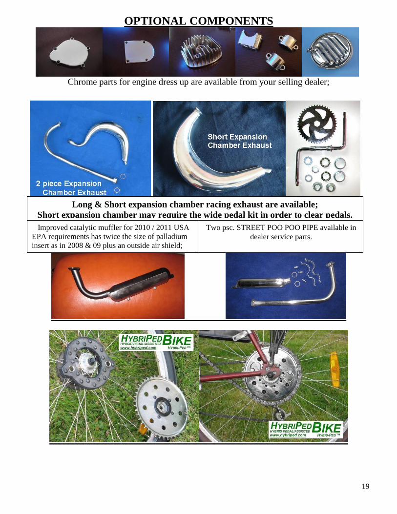
OPTIONAL COMPONENTS
Chrome parts for engine dress up are available from your selling dealer;
Long & Short expansion chamber racing exhaust are available;
Short expansion chamber may require the wide pedal kit in order to clear pedals.
Improved catalytic muffler for 2010 / 2011 USA
EPA requirements has twice the size of palladium
insert as in 2008 & 09 plus an outside air shield;
Two psc. STREET POO POO PIPE available in
dealer service parts.

20
Engine Shift-Kit for multi speed bikes.
Wanna Pedal unrestricted? Just pull 2 pins and pedal freely. Wanna Motor? Then just stick’em back in.
21
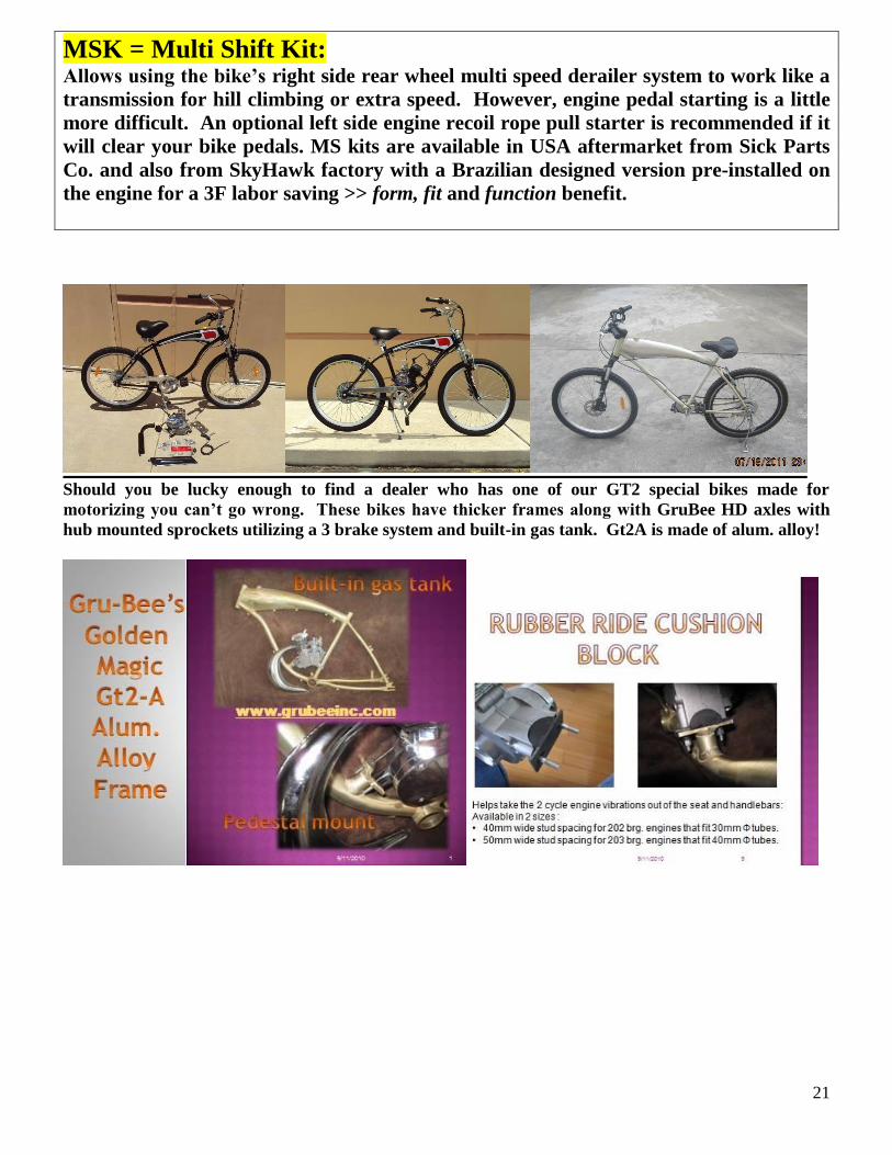
MSK = Multi Shift Kit: Allows using the bike’s right side rear wheel multi speed derailer system to work like a
transmission for hill climbing or extra speed. However, engine pedal starting is a little
more difficult. An optional left side engine recoil rope pull starter is recommended if it
will clear your bike pedals. MS kits are available in USA aftermarket from Sick Parts
Co. and also from SkyHawk factory with a Brazilian designed version pre-installed on
the engine for a 3F labor saving >> form, fit and function benefit.
Should you be lucky enough to find a dealer who has one of our GT2 special bikes made for
motorizing you can’t go wrong. These bikes have thicker frames along with GruBee HD axles with
hub mounted sprockets utilizing a 3 brake system and built-in gas tank. Gt2A is made of alum. alloy!

22
GT2A frames w/ rubber mt. are now available for WD distribution:

23
#4 CNS YuanDong SkyHawk Carb.

24
CNS Carburetor p/n C-32CNS66-EPA
#11
Air Cleaner
25
NT &
Speed
Carbs

26
C. For Standard NT and SPEED carb. ( Not for #1 or #2 CNS Carbs.)
2.5 liter gas tank
plated inside to
help reduce rust
from occuring
4
36T or 44T or 48T or 56T
REAR WHEEL SPROCKET
Drive Sprocket

27

28
The ETHANOL 101 Home Study Course What you need to know about Ethanol fuel when used in small engines;
Outdoor power equipment dealers and mechanics are finding themselves dealing with a flood of frustrated
owners experiencing engines not running right or having gummed up carburetors only to bring them back a
month or so later with the same complaint. What the customer does not realize is that the problem is not the
engine! It’s the fuel!!!!
The introduction of ethanol, otherwise known as alcohol, into the fuel has caused a wide range of problems.
While ethanol is regarded as a fuel, blending it with gasoline results in these 4 conditions.
Rough idle:
Hard starting after leaving the engine sit idle, ( not used ), for several weeks :
Gummed–up carburetor jet:
Loss of power:
Ethanol in gasoline breaks down and forms gums very quickly. Ethanol and Gasoline do not chemically bond
with each other, instead they are held together in a loose colloidal suspension much like you would see in an oil
and vinegar salad dressing mix. The fact is ordinary fuel adjustment additives developed 50 years ago and still
on the market today do not correct these 4 ethanol problems.
1. Debris in gasoline caused by Ethanol. Varnish Gums form in the fuel tank and in the carburetor bowl as E5, E10 & E15 ethanol fuel ages. These
particles can clog Filters and Needle Jets. Modern day fuel additives break down the enzymes into sub micron
sized particles that can be easily burned during the combustion process.
2. Excessive water in the fuel and phase separation. Ethanol attracts moisture from the atmosphere and forms a ethanol and water mix in the gasoline. Ethanol
blended fuel will naturally hold 0.5% water in separation, but when water levels exceed this threshold, or
when fuel cools significantly, the water/ethanol mix drops out of suspension which is called phase separation.
Excessive water in the fuel causes engines to run rough, stall and can lead to internal engine damage. A good
fuel additive allows the water to mix with the fuel and get burned off to create a dried out tank result.
3. Ethanol fuel breaks down quickly. As ethanol evaporates the fuel looses octane and becomes what is known as “stale”. This causes hard starts
and engine rattle as well as loss of power and engine damage. A good fuel additive will enhance correction to
fuel break down for up to 2 years.
4. Ethanol causes lost power and lost performance. Ethanol added to fuel does not allow as much energy as traditional gasoline. This results in poor engine
performance. A good adjustment additive will break apart large clusters of fuel molecules, creating more
surface area. This in turn allows additional oxygen to react during combustion which results in complete fuel
burning and reduces toxic exhaust emission.
The laws of some states in the USA do not require the gas station to tell you how much ethanol is in the gas
they sell. E-10 or 10% is supposed to be the legal ethanol limit but up to 50% has been found in some off-
brand gasoline. Adding a dry gas additive is not the answer either as these products contain more alcohol
which now you know is really Ethanol and will just accelerate the problem into the realm of the third kind.
Having said all the bad news here’s some good news! There are some additives on the market that will in
fact correct the short comings of having Ethanol in gasoline and will allow easy starting even after extended
long periods of not running the engine. These additives must contain enzymes that allow more oxygen to bond
with the fuel hydrocarbons thus allowing a more complete combustion burn of the fuel charge. This translates
into these advantages.
Easier Engine Starting:
Better throttle response:
Decreased exhaust emissions and decreased visible exhaust smoke:
Prevention of varnish gum deposits:
Increased fuel economy:
Helps prevent Phase Separation that can occur in stored fuel when water and ethanol bond together and
then falls out resulting in degraded fuel that prevents good engine performance.
The best policy is to avoid using any gasoline with Ethanol in it. This 101 article does not recommend any
brand of additive for Ethanol correction, however here’s a brand claiming to have benefit;
StarTron WWW.STARTRON.COM
29
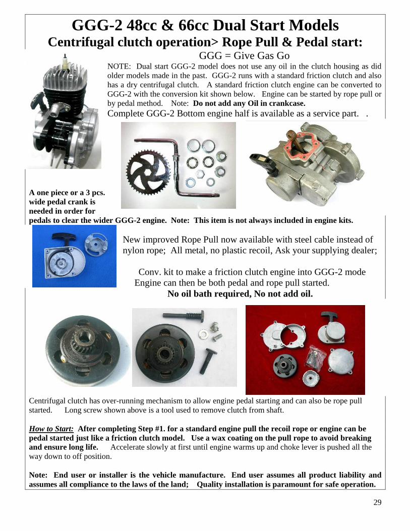
GGG-2 48cc & 66cc Dual Start Models Centrifugal clutch operation> Rope Pull & Pedal start:
GGG = Give Gas Go NOTE: Dual start GGG-2 model does not use any oil in the clutch housing as did
older models made in the past. GGG-2 runs with a standard friction clutch and also
has a dry centrifugal clutch. A standard friction clutch engine can be converted to
GGG-2 with the conversion kit shown below. Engine can be started by rope pull or
by pedal method. Note: Do not add any Oil in crankcase.
Complete GGG-2 Bottom engine half is available as a service part. .
A one piece or a 3 pcs.
wide pedal crank is
needed in order for
pedals to clear the wider GGG-2 engine. Note: This item is not always included in engine kits.
New improved Rope Pull now available with steel cable instead of
nylon rope; All metal, no plastic recoil, Ask your supplying dealer;
Conv. kit to make a friction clutch engine into GGG-2 mode
Engine can then be both pedal and rope pull started.
No oil bath required, No not add oil.
Centrifugal clutch has over-running mechanism to allow engine pedal starting and can also be rope pull
started. Long screw shown above is a tool used to remove clutch from shaft.
How to Start: After completing Step #1. for a standard engine pull the recoil rope or engine can be
pedal started just like a friction clutch model. Use a wax coating on the pull rope to avoid breaking
and ensure long life. Accelerate slowly at first until engine warms up and choke lever is pushed all the
way down to off position.
Note: End user or installer is the vehicle manufacture. End user assumes all product liability and
assumes all compliance to the laws of the land; Quality installation is paramount for safe operation.