YRL LKFTSINSTL FUL Rev C LETTER 1-9
28
P/N YRL-LKFTSINSTL-FUL Rev C #7 wood & #8-32 machine x 20mm Combination screws x4 M4 x 22mm Pan head machine screws x2 #8-32 x 5/16" Machine screws x2 Battery Cover Key AA Alkaline Batteries Latch Strike Plate Interior Mounting Plate Interior Lock Battery Cover Template Levers ® ® ™ Yale Assure Lever Key Free Touchscreen Installation and Programming Instructions (YRL256) Optional Smart Module* Key Free Cylinder *Yale Smart Module is not included with YRL236-NR models. FAILURE TO FOLLOW THESE INSTRUCTIONS COULD RESULT IN DAMAGE TO THE PRODUCT AND VOID THE FACTORY WARRANTY Before you begin for step-by-step installation instructions & to register your product DOWNLOAD THE BILT APP WARNING This product can expose you to lead which is known to the state of California to cause cancer and birth defects or other reproductive harm. For more information go to www.P65warnings.ca.gov.
Transcript of YRL LKFTSINSTL FUL Rev C LETTER 1-9

P/N YRL-LKFTSINSTL-FUL Rev C
1
#7 wood & #8-32machine x 20mm
Combination screws
x4
M4 x 22mmPan head machine
screws
x2
#8-32 x 5/16"Machine screws
x2
Battery CoverKey
AA AlkalineBatteries
Latch
Strike Plate
Interior Mounting PlateInterior Lock
Battery Cover
Template
Levers
®
® ™Yale Assure Lever Key Free TouchscreenInstallation and Programming Instructions
(YRL256)
OptionalSmart Module*
Key FreeCylinder
*Yale Smart Moduleis not included withYRL236-NR models.
FAILURE TO FOLLOW THESE INSTRUCTIONS COULD RESULT IN DAMAGE TO THE PRODUCT AND VOID THE FACTORY WARRANTY
Before you begin
for step-by-step installationinstructions & to register
your product
DOWNLOADTHE BILT APP
WARNINGThis product can expose you to lead which is known to the state of California to cause cancer and birth defects or other reproductive harm. For more information go to www.P65warnings.ca.gov.

P/N YRL-LKFTSINSTL-FUL Rev C
2
Preparing to Install
Utility Knife
Drill Wood MortiseChisel
PencilTape
Measure
Level
Tools necessary only for new doors or adjusting existing prep.
Template
Tools Needed
StandardPhillips HeadScrewdriver

P/N YRL-LKFTSINSTL-FUL Rev C
3
Checking Measurements
2-3/8" or 2-3/4"(60mm or 70mm)
Backset
2-1/8" (54mm)Diameter
1-3/8" or 1-3/4"(35mm or 44.5mm)
Door Thickness
1" (25mm)Diameter

P/N YRL-LKFTSINSTL-FUL Rev C
4
? Determining Door Handing
Left Hand Right Hand
Face a door swinging openaway from you.
If it swings open to the right, it is a right hand door. If it
swings open to the left, it is a left hand door.
Exterior
Inswinging DoorInterior Left Hand
ReverseRight Hand
Reverse
Face a door swinging open toward you.
If it swings open to the right, it is a right hand reverse door. If it swings opens to the left, it is a
left hand reverse door.
Exterior
Outswinging Door
Interior
Outside of Door
Curve of latchbolt must contact strike plate first.
Frame
Door
Latchbolt Curve
Strike Plate
Exterior
!
OptionalSmart Module
Inside of Door

P/N YRL-LKFTSINSTL-FUL Rev C
5
Preparing Door & FrameNecessary for new doors or adjusting existing prep.
1" (25mm)Deep
Inside of Door
FrameFrame
!Drill holes 1/2 way through door then
complete from other side to prevent splitting.
2-1/8"(54mm)
Dia.
2-3/8" (60mm)or
2-3/4" (70mm)Backset
1"(25mm)
Dia.

P/N YRL-LKFTSINSTL-FUL Rev C
6
x4
1 Installing Latch & Strike PlateRight Hand Installation Shown
2-3/8" through bolt posts
2-3/4" through bolt postsNote: Adjustment based on backsetO
optional
default
PULL
Outsideof Door
Frame*Backset
*2-3/8" (60mm) or 2-3/4" (70mm)

P/N YRL-LKFTSINSTL-FUL Rev C
7
2
Outside of Right Hand Door
Inside of Right Hand Door
Installing TouchscreenRight Hand Installation Shown
!
!
“TOP” mark must be on top surface and tailpiece
in vertical position.
Incorrect orientation willcause lock to fail.

P/N YRL-LKFTSINSTL-FUL Rev C
8
x2
3 Installing Interior Mounting Plate Right Hand Installation Shown
Inside of Right Hand Door
Inside of Right Hand Door

9
4
P/N YRL-LKFTSINSTL-FUL Rev C
Attaching the Cable AssemblyRight Hand Installation Shown
!Use cablehooks for
proper cablerouting.
Inside of Right Hand Door
! Ensure cable is securely fastened into adapter.

P/N YRL-LKFTSINSTL-FUL Rev C
10
5
X2
Installing Interior LockRight Hand Installation Shown
X
Inside of Right Hand
Door
“Click”

P/N YRL-LKFTSINSTL-FUL Rev C
11
6 Installing Exterior Key Free Cylinder
Outside of Right Hand Door
! Key free cylinder must be installedwith bar away from latch.
Bar
Latch
P/N YRL-LKFTSINSTL-FUL Rev C
12
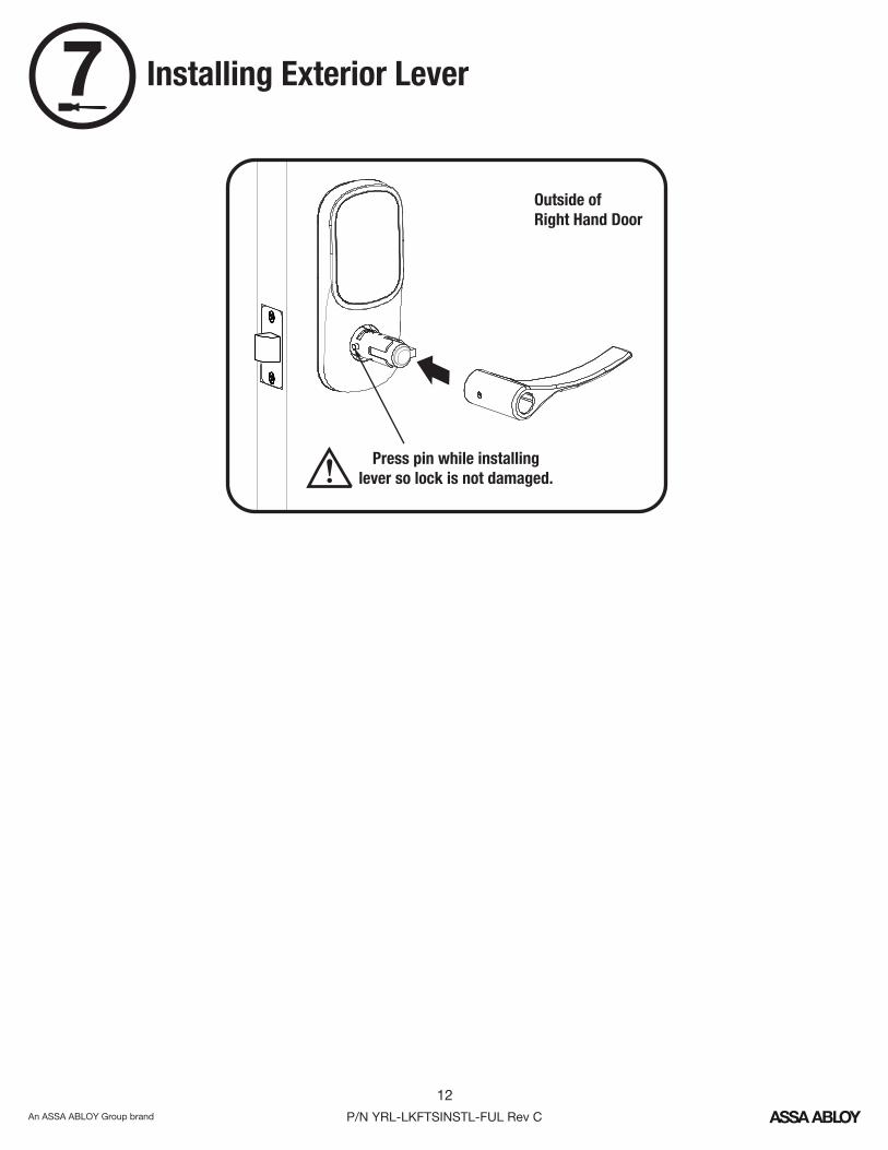
7 Installing Exterior Lever
Outside of Right Hand Door
! Press pin while installinglever so lock is not damaged.

P/N YRL-LKFTSINSTL-FUL Rev C
13
8 Installing Interior Lever
Inside of Right Hand Door
! Press pin while installinglever so lock is not damaged.

P/N YRL-LKFTSINSTL-FUL Rev C
14
Testing Mechanical Operation
Outside of Right HandDoor
Outside of Right HandDoor
! Test interior and exterior operation with door open.
!Test thumbturn and both levers in locked and unlocked positions. If operation fails, check installation beginning with Step 3 and refer toHardware Troubleshooting.

P/N YRL-LKFTSINSTL-FUL Rev C
15
9 Installing Optional Smart Module(if included)
NOTE: If a Smart module was included with your lock, itis in a separate box with additional module installationinstructions.
Inside of Right Hand Door
!Batteries must not be
installed prior to insertingand/or removing module.

P/N YRL-LKFTSINSTL-FUL Rev C
16
10 Installing Batteries & Cover
Congratulations, you've installed the® ™Yale Assure Lever Key Free Touchscreen ( )!YRL256
Using Your Lock instructions will helpyou customize your lock.
Inside of Right Hand Door
"Welcome toYale Real Living."

P/N YRL-LKFTSINSTL-FUL Rev C
17
Testing Touchscreen Operation
! Test with door open.
A Master Enty Code must be created upon installation or after resetting the lock to factory default. Programming and use of lock is not possible until this step has been successfully completed. See of Programming Instructions below.
1
Enter Entry Code Press
!
Enter Entry Code Press
If touchscreen operation test fails, check installation beginning with Step 2.
OR

18P/N YRL-LKFTSINSTL-FUL Rev C
Resetting Lock to Factory Default
4. Re-insert 3 batteries and hold the reset button for 3 seconds.
5. While still holding the reset button, insert the 4th battery, and hold the reset button for an additional 3 seconds.
7. Re-install the interior lock onto the door.
*Upon reset, Master Entry Code creation is the only option available and must be performed prior to any other programming of the lock.
3. The reset button (see image above) is marked.
1. Remove the battery cover and batteries.
6. Release the reset button.
2. Remove the interior lock to access the reset button.
When resetting the lock, all user codes, including the Master Entry Code*, are deleted. All programming features are reset to original default settings. See “Factory Settings”.
Reset Button
Interior Lock

P/N YRL-LKFTSINSTL-FUL Rev C
19
Hardware Troubleshooting
Cycle lock in both the locked and unlocked positions. If problems are found:
Tailpiece and spindle will not mate and fit into the interior escutcheon
a. Ensure that your door is between 1-3/8" and 1-3/4" thickb. Ensure that the square shaped spindle has “Top” writing and arrow facing upwards c. Place the tailpiece in the vertical positiond. Verify that the thumb turn is in the horizontal (unlocked) position
Thumbturn does not rotate electronically or physically
a. Verify that inside of the lock is properly seated on the mounting bracket b. Ensure that the square shaped spindle has “Top” writing and arrow facing upwardsc. Place the tailpiece in the vertical positiond. Verify that the thumb turn is in the horizontal (unlocked) position
I'm getting an alert when I try to lock or unlock the door electronically
a. Do not turn or depress the lever during operation, this could cause a jam alarmb. Check that thumb turn does not have anything preventing it from physically rotatingc. Verify that you can rotate thumb turn freely
My lock is not making any sound when I push buttons
a. Using the programming tree in the manual to verify that Audio is enabledb. If Audio is enabled, ensure that the white cable, that connects the keypad to the interior of the lock, is not pinched or broken
When rotating the thumbturn I hear noise
a. A little bit of noise is normal when operating the thumbturnb. If cranking, grinding or clicking occurs please verify your installation
The locking pins will not retract when I try to install the levers
a. If the thumb turn is in vertical (locked) position, rotate the thumb turn the horizontal (unlocked) position and it will retract
®While Yale has included several features to prevent lockout (9-Volt battery jumper, low battery warnings), it is still possible for a lockout situation to occur. Because this product does not
®have a mechanical override (a key), Yale recommends to use this product in an environment where there are additional entry points into the dwelling.
NOTE TO INSTALLER AND CONSUMER

P/N YRL-LKFTSINSTL-FUL Rev C
20
Setting Definitions
*The Master Entry Code must be created prior to any other programming of the lock.
Creationrequired*
Settings Default Setting
Master Entry Code
Definition
The Master Entry Code is used for programming and for feature settings. It must be created prior to programming the lock. The Master code will also operate (unlock/lock) the lock.
Auto Re-lock Disabled
After a successful code entry or manual unlock with the key, the lock will automatically re-lock after each unlock in an effort to keep your home secure. This feature is optional, and can be turned off. In the ON mode, the lock will automatically re-lock after thirty (30) seconds.
Inside Indicator Light Disabled (Off)
Located on the interior lock. Shows active status (Locked) of lock and can be enabled or disabled in the Advanced Lock Settings (Main Menu selection #3).
One Touch Locking Enabled
When the latch is retracted, activating the keypad will extend the latch (during Auto Re-lock duration or when Auto Re-lock is disabled). When One-Touch Re-lock is not in use (disabled), any valid PIN code will re-lock the lock.
Volume Enabled (Low)The volume setting for entry code verification is set to Low (2) by default; otherwise it can be set to High (1) or Silent (3) for quiet areas.
Language EnglishChoosing English (1), Spanish (2) or French (3) becomes the (default) setting for the lock's voice prompts.
All Code Lockout Mode Disabled
This feature is enabled by the Master Entry Code. When enabled, it restricts all user (except Master) Entry Code access. When attempting to enter a code while the lock is in All Code Lockout mode, the RED locked padlock will appear on the screen.
Wrong Code Entry Limit 5 TimesAfter five (5) unsuccessful attempts at entering a valid entry code, the lock will shut down and not allow operation for sixty (60) seconds.
Shutdown Time 60 SecondsThe Lock will shutdown (flashing RED) for sixty (60) seconds and not allow operation after the wrong code entry limit (5 attempts) has been met.

P/N YRL-LKFTSINSTL-FUL Rev C
21
Using Your Lock
Touchscreen Keypad
Speaker
Press to return to previous Settings Menu
Low BatteryIndicator
All Code Lockout ModeIndicator
Battery Back-upHold a 9V battery to theterminals in case of deadlock batteries
Press to wake keypador lock door
Enter Master Entry Codeand press to accessSettings Menu
Press to enteror unlock
Interior Lock
Thumbturn
Inside Indicator LightSpeaker

P/N YRL-LKFTSINSTL-FUL Rev C
22
1 Creating Master Entry Code
Enter 4-8digit MasterEntry Code
Creating a Master Entry Code must be performed upon installation or after resetting the lock to factory default. Programming and use of lock is not possible until this step has been successfully completed.
Press
Press
"Register MasterCode. Press the gear
key to continue."
"Enter a 4 to 8 digitPIN code followed by
the gear key."
"Registered."

P/N YRL-LKFTSINSTL-FUL Rev C
23
2 Creating User Entry Codes
Enter MasterEntry Code
Press Press
Press
Press Press
Master Entry Code must be created first.*Max user codes = 250 with Smart Module and 25 without.
Press
Adding more User Codes:
Enter 4-8 digit Entry CodePress
To end programming:
Enter 4-8 digit Entry CodePress (code flashes)
Press
"Menu Mode, enter number,
press the gear key to continue."

P/N YRL-LKFTSINSTL-FUL Rev C
24
3 Deleting User Entry Codes
Enter MasterEntry Code
Press Press
Press Press
Deleting one entry code:
Enter 4-8 digit entry code
Press
To delete all entry codes(Does not delete Master Entry Code):
"Menu Mode,enter number,
press the gear keyto continue."
Press
Press Enter
To delete one entry code, you must enter the entry code you wish to delete.

P/N YRL-LKFTSINSTL-FUL Rev C
25
4 Unlocking Door with Entry Code
Duplicate if necessary Code Chart
User Name:
Entry Code
Master:
Entry Code Management
Enter Entry Code Press

26P/N YRL-LKFTSINSTL-FUL Rev C
Customizing Lock Through Settings Menu*Master Entry Code Required
Join the Network
Enable
Disable
English
Spanish
French
Silent
Low
High
Exit the Network
Volume Setting
Language Setting Mode
All Code Lockout Mode
**Network Module Setting
Default settings in bold.
AdvancedLock Settings
Auto Re-lock Disable 30 sec
Inside Indicator Light
One Touch Locking Enable Disable
Enable
60 sec
3 min
2 min
Disable
1. Press Yale logo to wake up lock .2. Enter Master Entry Code* followed by icon. Lock Response: "Welcome to the Settings Menu. Press each number to hear available settings and then press the settings icon to enter."3. Enter digit corresponding to the function to be performed followed by the icon. Follow the voice commands.
*The Master Entry Code must be created prior to any other programming of the lock.**Network Module Setting function appears only with Yale Smart module installed.
Here is an example of how to set Auto Lock to 30 seconds:
Master Entry Code , 3 , 1 , 2 ,
Exit SettingsMenu
Remainin Settings Menu
OR
OR
OR
OR
OR

27P/N YRL-LKFTSINSTL-FUL Rev C
Programming Troubleshooting
Symptom Suggested Action
•
•
•
•
Lock operates to allow access, but will not automatically re-lock.
• • • • • •
•
•
•
•
* When batteries are replaced, Smart Module locks have a real time clock that will be set through the User Interface (UI); it is recommended to verify correct date and time particularly those locks operating under Daylight Saving Time (DST).
•
Yale keypad becomes active when the Yale logo is pressed. Verify contact with the logo.If keypad numbers are visible, check to see if they respond when pressed.Check batteries are installed and oriented correctly (polarity) in battery case.Check batteries are in good condition; replace batteries* if batteries are dead.Check to see if keypad cable is fully connected and is not pinched.
• • Apply a 9V battery to terminals below the keypad for
backup power option.
Batteries may not have enough power. Replace batteries*.
Check that the cable is firmly connected to the interior lock.
Check to see if Auto Re-lock is enabled.Disable Auto Re-lock to lock the door (manually).If low battery indicator is lit, change batteries*.
Entry codes must consist of 4 to 8 digits.The same entry code cannot be used for multiple users.Management of entry codes is set by the authority of the Master Code, which is set first. Contact the Master user.
Entry codes must be entered within 5 seconds (while keypad is active) or process will have to be restarted.Check or gear cannot be used as part of the entry code.
All Code Lockout Mode is enabled. Only the Master Entry Code can enable/disable All Code Lockout Mode. Contact the Master user.
• Check to see if the lock is set to All Code Lockout Mode. Setting/managing All Code Lockout Mode is done through Master Entry Code only. Contact Master user.
Check to see if Volume is set to Silent (see Feature #4).
• The digits entered were incorrect or incomplete. Re-enterthe correct code followed by the check key.
• Verify entered code is a valid, previously programmed, 4 to 8 digit code.

28P/N YRL-LKFTSINSTL-FUL Rev C
Product Support Tel 1-855-213-5841 • www.yalehome.com
Ÿ Reorient or relocate the receiving antenna.
Ÿ Consult the dealer or an experienced radio/TV technician for help.
This equipment has been tested and found to comply with the limits for a Class B digital device, pursuant to Part 15 of the FCC Rules. These limits are designed to provide reasonable protection against harmful interference in a residential installation. This equipment generates, uses, and can radiate radio frequency energy and, if not installed and used in accordance with the instructions, may cause harmful interference to radio communications. However, there is no guarantee that interference will not occur in a particular installation. If this equipment does cause harmful Interference to radio or television reception, which can be determined by turning the equipment off and on, the user is encouraged to try to correct the interference by one or more of the following measures:
Ÿ Increase the separation between the equipment and receiver.
Class B Equipment FCC:
Ÿ Connect the equipment into an outlet on a circuit different from that to which the receiver is connected.
Industry Canada:
Cet appareillage numérique de la classe A répond à toutes les exigences de l'interférence canadienne causant des règlements d'équipement. This Class A digital apparatus meets all requirements of the Canadian Interference Causing Equipment Regulations.
Warning: Changes or modifications to this device, not expressly approved by ASSA ABLOY Residential Group could void the user's authority to operate the equipment.
Yale® and Yale Real Living® are registered trademarks of ASSA ABLOY Residential Group. Assure Lever™ is a trademark of ASSA ABLOY Residential Group.
Other products' brand names may be trademarks or registered trademarks of their respective owners and are mentioned for reference purposes only.
© Copyright 2019. All rights reserved. Reproduction in whole or in part without the express written permission of ASSA ABLOY Residential Group is prohibited.