Your Comments - University Of Illinois · Your Comments I work as an audio technician, and I've...
22
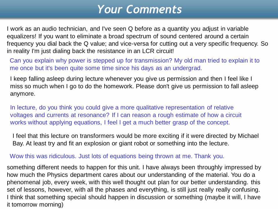
Your Comments I work as an audio technician, and I've seen Q before as a quantity you adjust in variable equalizers! If you want to eliminate a broad spectrum of sound centered around a certain frequency you dial back the Q value; and vice-versa for cutting out a very specific frequency. So in reality I'm just dialing back the resistance in an LCR circuit! Can you explain why power is stepped up for transmission? My old man tried to explain it to me once but it's been quite some time since his days as an undergrad. I keep falling asleep during lecture whenever you give us permission and then I feel like I miss so much when I go to do the homework. Please don't give us permission to fall asleep anymore. In lecture, do you think you could give a more qualitative representation of relative voltages and currents at resonance? If I can reason a rough estimate of how a circuit works without applying equations, I feel I get a much better grasp of the concept. I feel that this lecture on transformers would be more exciting if it were directed by Michael Bay. At least try and fit an explosion or giant robot or something into the lecture. Wow this was ridiculous. Just lots of equations being thrown at me. Thank you. something different needs to happen for this unit. I have always been throughly impressed by how much the Physics department cares about our understanding of the material. You do a phenomenal job, every week, with this well thought out plan for our better understanding. this set of lessons, however, with all the phases and everything, is still just really really confusing. I think that something special should happen in discussion or something (maybe it will, I have it tomorrow morning)
Transcript of Your Comments - University Of Illinois · Your Comments I work as an audio technician, and I've...
Your Comments
I work as an audio technician, and I've seen Q before as a quantity you adjust in variable
equalizers! If you want to eliminate a broad spectrum of sound centered around a certain
frequency you dial back the Q value; and vice-versa for cutting out a very specific frequency. So
in reality I'm just dialing back the resistance in an LCR circuit!
Can you explain why power is stepped up for transmission? My old man tried to explain it to
me once but it's been quite some time since his days as an undergrad.
I keep falling asleep during lecture whenever you give us permission and then I feel like I
miss so much when I go to do the homework. Please don't give us permission to fall asleep
anymore.
In lecture, do you think you could give a more qualitative representation of relative
voltages and currents at resonance? If I can reason a rough estimate of how a circuit
works without applying equations, I feel I get a much better grasp of the concept.
I feel that this lecture on transformers would be more exciting if it were directed by Michael
Bay. At least try and fit an explosion or giant robot or something into the lecture.
Wow this was ridiculous. Just lots of equations being thrown at me. Thank you.
something different needs to happen for this unit. I have always been throughly impressed by
how much the Physics department cares about our understanding of the material. You do a
phenomenal job, every week, with this well thought out plan for our better understanding. this
set of lessons, however, with all the phases and everything, is still just really really confusing.
I think that something special should happen in discussion or something (maybe it will, I have
it tomorrow morning)
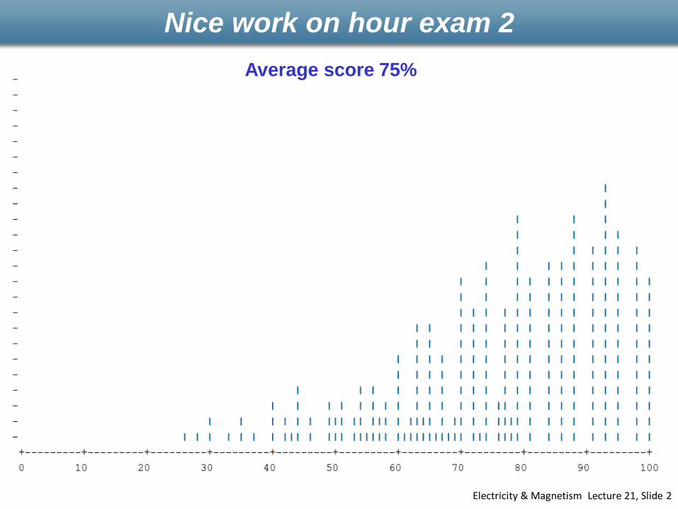
Nice work on hour exam 2
Electricity & Magnetism Lecture 21, Slide 2
Average score 75%

Physics 212
Lecture 21

Looks intimidating, but isn’t bad!
Electricity & Magnetism Lecture 21, Slide 4

Peak AC Problems
XL
XC
R
“Ohms” Law for each element NOTE: Good for PEAK values only)
Vgen = Imax Z
VResistor = Imax R
Vinductor = Imax XL
VCapacitor = Imax XC
Typical ProblemA generator with peak voltage 15 volts and angular frequency 25 rad/sec is
connected in series with an 8 Henry inductor, a 0.4 mF capacitor and a 50 ohm
resistor. What is the peak current through the circuit?
L
R
C 22
CL XXRZ =
LX L =
CXC
1=
== 12222
CL XXRZ== 200LXL
== 1001
CXC
A
Z
VI
gen13.0max ==

Which element has the largest peak voltage across it?
A) Generator E) All the same.
B) Inductor
C) Resistor
D) Capacitor
Peak AC Problems
“Ohms” Law for each element NOTE: Good for PEAK values only)
Vgen = Imax Z
VResistor = Imax R
Vinductor = Imax XL
VCapacitor = Imax XC
Typical ProblemA generator with peak voltage 15 volts and angular frequency 25 rad/sec is
connected in series with an 8 Henry inductor, a 0.4 mF capacitor and a 50 ohm
resistor. What is the peak current through the circuit?
L
R
C 22
CL XXRZ =
LX L =
CXC
1=
XL
XC
R
== 200LXL
== 1001
CXC
== 12222
CL XXRZ
AZ
VI
gen13.0max ==XIV maxmax =

Peak AC Problems
What happens to the impedance if we decrease the angular frequency to 20 rad/sec?
A) Z increases
B) Z remains the same
C) Z decreases (XL XC): (200 100) -> (160 125)
Z25Z20
XC
R
XL
“Ohms” Law for each element NOTE: Good for PEAK values only)
Vgen = Imax Z
VResistor = Imax R
Vinductor = Imax XL
VCapacitor = Imax XC
Typical ProblemA generator with peak voltage 15 volts and angular frequency 25 rad/sec is
connected in series with an 8 Henry inductor, a 0.4 mF capacitor and a 50 ohm
resistor. What is the peak current through the circuit?
L
R
C 22
CL XXRZ =
LX L =
CXC
1=
XL
XC
R

Light-bulb Demo
Resonance

Resonance
R is independent of
Frequency at which voltage across inductor and capacitor cancel
RXC
Z
XL
0
Z = R at resonance
XL increases with
LLX =
XC increases with 1/
CXC
1=
is minimum at resonance
22 )( CL XXRZ =
Resonance: XL = XC LC
10 =

Z
In general
Umax = max energy storedDU = energy dissipated
in one cycle at resonance
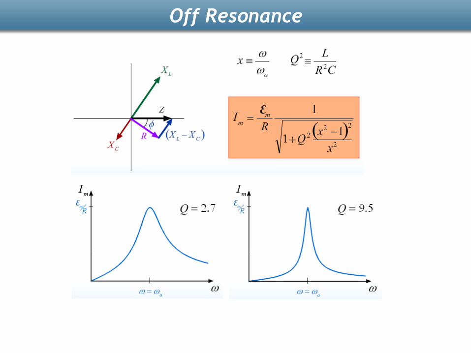
Off Resonance
U
UQ
D max2
Off Resonance

Imax XL
Imax XC
Imax R
Case 1
Imax XL
Imax XC
Imax R
Case 2
Resonance: XL = XC
Z = R
Same since R doesn't change
CheckPoint 1a
Consider two RLC circuits with identical generators and resistors.
Both circuits are driven at the resonant frequency. Circuit II has twice
the inductance and 1/2 the capacitance of circuit I as shown above.
Compare the peak voltage across the resistor in the two circuits
A. VI > VII B. VI = VII C. VI < VII

Voltage in second circuit will be twice that of the first because of the 2L compared to L.
CheckPoint 1b
Imax XL
Imax XC
Imax R
Case 1
Imax XL
Imax XC
Imax R
Case 2
Consider two RLC circuits with identical generators and resistors.
Both circuits are driven at the resonant frequency. Circuit II has
twice the inductance and 1/2 the capacitance of circuit I as shown
above.Compare the peak voltage across the inductor in the
two circuits
A. VI > VII B. VI = VII C. VI < VII
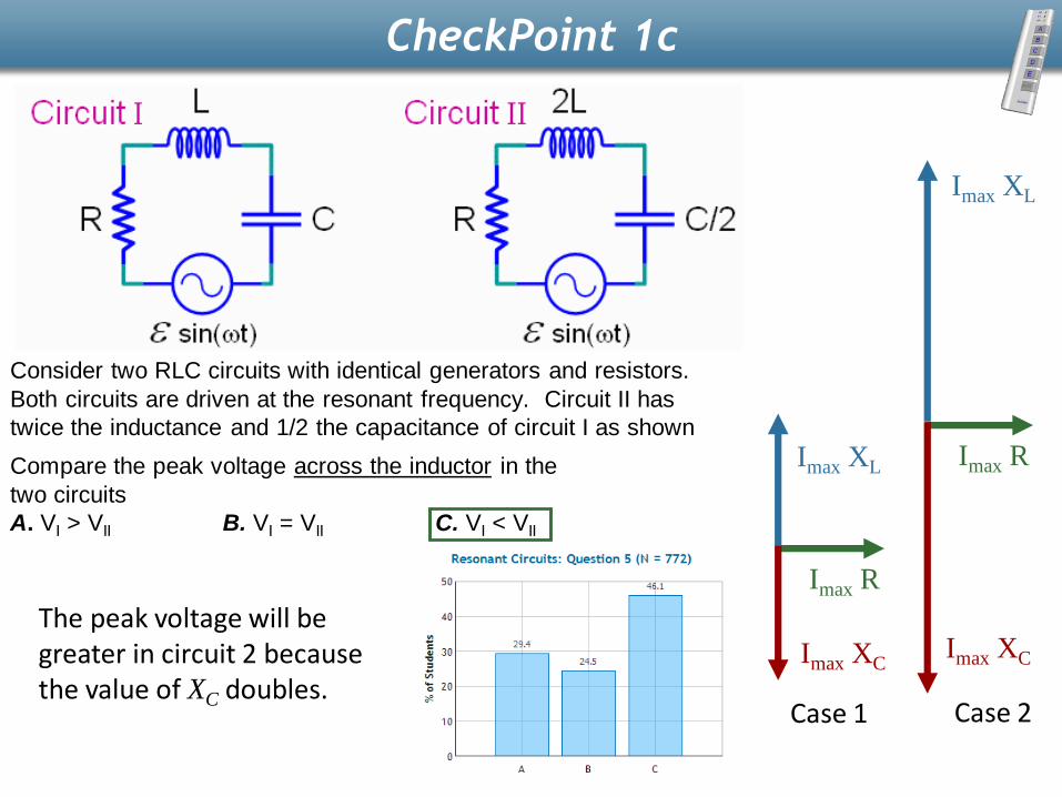
The peak voltage will be greater in circuit 2 because the value of XC doubles.
CheckPoint 1c
Imax XL
Imax XC
Imax R
Case 1
Imax XL
Imax XC
Imax R
Case 2
Consider two RLC circuits with identical generators and resistors.
Both circuits are driven at the resonant frequency. Circuit II has
twice the inductance and 1/2 the capacitance of circuit I as shown
above.Compare the peak voltage across the inductor in the
two circuits
A. VI > VII B. VI = VII C. VI < VII

The voltage across the inductor and the capacitor are equal when at resonant frequency, so there is no lag or lead.
CheckPoint 1D
Imax XL
Imax XC
Imax R
Case 1
Imax XL
Imax XC
Imax R
Case 2
Consider two RLC circuits with identical generators and resistors.
Both circuits are driven at the resonant frequency. Circuit II has
twice the inductance and 1/2 the capacitance of circuit I as shown
above.At the resonant frequency, which of the following is true?
A. Current leads voltage across the generator
B. Current lags voltage across the generator
C. Current is in phase with voltage across the generator

Power
P = IV instantaneous always true Difficult for Generator, Inductor and Capacitor because of phase
Resistor I,V are always in phase!
P = IV
= I2 R
RMS = Root Mean Square
Ipeak = Irms sqrt(2)
L
R
C
Average Power
Inductor and Capacitor = 0 ( < sin(t) cos(t) > = 0 )
Resistor
<I 2R> = <I 2 > R = ½ I 2peak R
< I 2 R > = Irms2 R

Power Line Calculation
If you want to deliver 1,500 Watts at 100 Volts over transmission lines w/ resistance of 5 Ohms. How much power is lost in the lines?
Current Delivered: I = P/V = 15 Amps
Loss = IV (on line) = I2 R = 15*15 * 5 = 1,125 Watts!
If you deliver 1,500 Watts at 10,000 Volts over the same transmission lines. How much power is lost?
Current Delivered: I = P/V = .15 Amps
Loss = IV (on line) = I2R = 0.125 Watts
DEMO
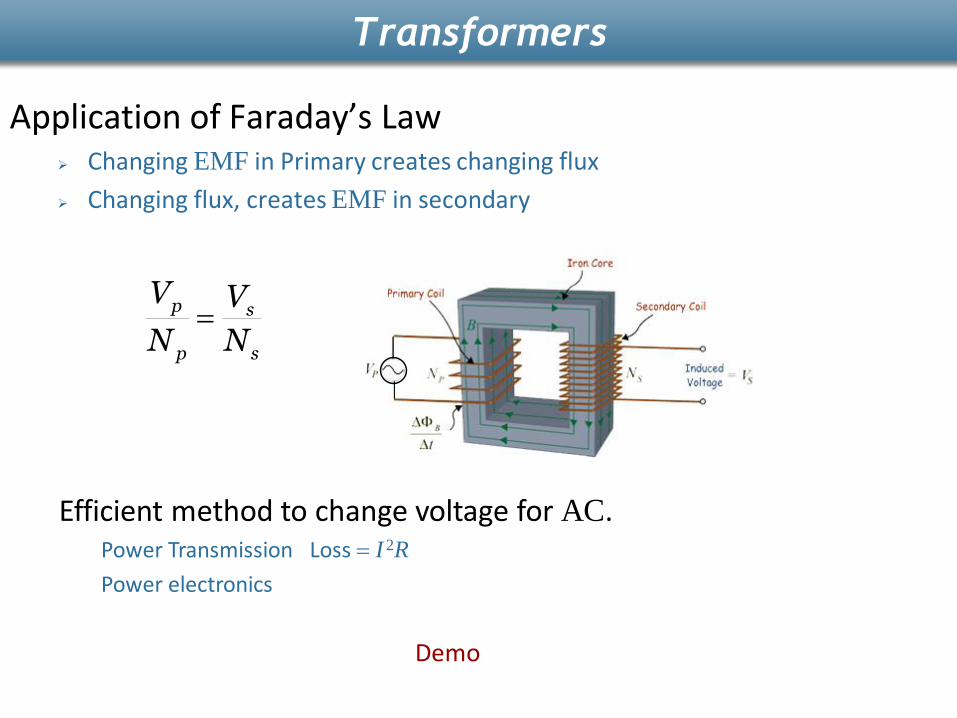
Application of Faraday’s Law Changing EMF in Primary creates changing flux
Changing flux, creates EMF in secondary
p s
p s
V V
N N=
Demo
Efficient method to change voltage for AC.Power Transmission Loss = I 2R
Power electronics
Transformers

Consider the harmonically driven series LCR circuit shown. Vmax = 100 V
Imax = 2 mA
VCmax = 113 V (= 80 sqrt(2))
The current leads generator voltage by 45o (cos = sin = 1/sqrt(2))
L and R are unknown.
How should we change to bring circuit to resonance?
A) decrease B) increase C) Not enough info
Original
f
At resonance (0) At resonance
XL = XC
Follow-Up from Last Lecture
increasesXL increases
XC decreases
C
R
LV

Consider the harmonically driven series LCR circuit shown. Vmax = 100 V
Imax = 2 mA
VCmax = 113 V (= 80 sqrt(2))
The current leads generator voltage by 45o (cos = sin = 1/sqrt(2))
L and R are unknown.
By what factor should we increase to bring circuit to resonance? i.e. if 0 = f, what is f?
A) B) C) D)
At resonance XL = XC
If is increased by a
factor of f:
XL increases by factor of f
XC decreases by factor of f
More Follow-UpC
R
LV= kXC 240
= kR 225
= kXL 215
2=f 22=f3
8=f
5
8=f
ff
4015 =
15
402 =f3
8=f
215 fXL
240/1 fXC

Consider the harmonically driven series LCR circuit shown. Vmax = 100 V
Imax = 2 mA
VCmax = 113 V (= 80 sqrt(2))
The current leads generator voltage by 45o (cos = sin = 1/sqrt(2))
L and R are unknown.
What is the maximum current at resonance ( Imax(0) )
At resonance XL = XC
Current Follow-UpC
R
LV= kXC 240
= kR 225
= kXL 215
A) B) C) mAI 20max = mAI 220max = mAI3
80max =
3
80 =
RZ = mAR
VI 22
225
100max0max ===

Phasor Follow-Up
Consider the harmonically driven series LCR circuit shown. Vmax = 100 V
Imax = 2 mA
VCmax = 113 V (= 80 sqrt(2))
The current leads generator voltage by 45o (cos = sin = 1/sqrt(2))
L and R are unknown.
What does the phasor diagram look like at t = 0? (assume V = Vmaxsint)
V = Vmax sint -> V is horizontal at t = 0 (V = 0)
A) B) C) D) XXX
C
R
LV
VL < VC if current leads generator voltage
= kR 225
= kXL 215
RCL VVVV
=