Your clear perspective“ in Flex / Flex-Rigid / FR4 …...Your „clear perspective“ in Flex /...
22
Your „clear perspective“ in Flex / Flex-Rigid / FR4 Semiflex Flex-Rigid Design Guide part II – how important are mechanical issues with flex-rigid pcbs? • mechanical construction • layout and wiring • documents for a flex-rigid circuit board • questions and suggestions from the last Webinar part I
Transcript of Your clear perspective“ in Flex / Flex-Rigid / FR4 …...Your „clear perspective“ in Flex /...

Your „clear perspective“ in
Flex / Flex-Rigid / FR4 Semiflex
Flex-Rigid Design Guide part II – how important are mechanical issues with flex-rigid pcbs?
• mechanical construction
• layout and wiring
• documents for a flex-rigid circuit board
• questions and suggestions from the last Webinar part I
Thesis: The Flex-Rigid Design Guide makes me happy!
the ultimate „proof“:
www.we-online.com/flexrigid Product management 3D Technology – V 2013 page 2 of 22

standard shapes, mechanical options
Cuboid Pyramid Cylinder
www.we-online.com/flexrigid Product management 3D Technology – V 2013 page 3 of 22

standard shapes, mechanical options
Triangle Box Toothing
www.we-online.com/flexrigid Product management 3D Technology – V 2013 page 4 of 22

standard shapes, mechanical options
Stack Fixing Fans
www.we-online.com/flexrigid Product management 3D Technology – V 2013 page 5 of 22

FR4 Semiflex: Pre-bending and fixation
accurately defined pre-bending prior to box assembly!
Assembly on
plastic housing:
www.we-online.com/flexrigid Product management 3D Technology – V 2013 page 6 of 22

bending radius, - angle, flexible length - formulae
flex-rigid
FR4 Semiflex
www.we-online.com/flexrigid Product management 3D Technology – V 2013 page 7 of 22
IPC-2223: Use A (Flex-to-install):
R: Thickness flex x 10

Next up, we do a….
What do you guess:
Which one is the main cost driver with flex-rigid?
www.we-online.com/flexrigid Product management 3D Technology – V 2013 page 8 of 22

number of flexible layers !!
number of process steps
area
– unfavourable flex extensions
– distribution
– length
– delivery panel
number of layers rigid area, via-technology
IPC2223 use B
material (Polyimide 50µm / 75µm / 100µm)
coverlay – flexible soldermask
some cost drivers
www.we-online.com/flexrigid Product management 3D Technology – V 2013 page 9 of 22
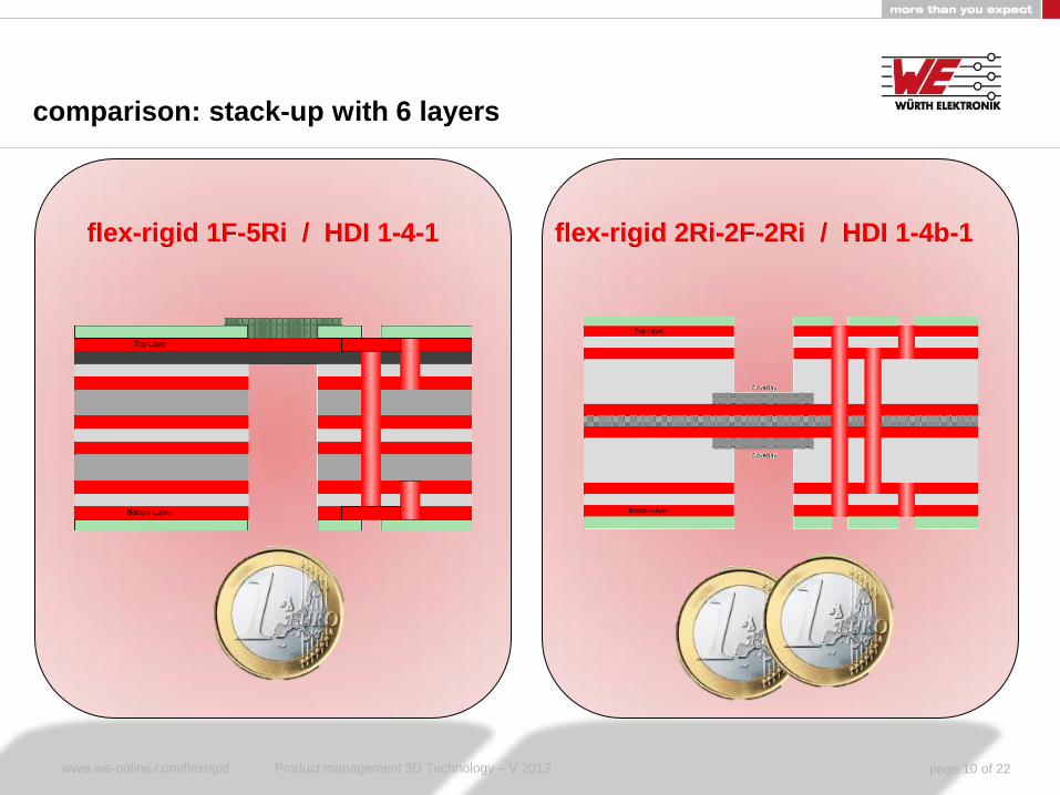
comparison: stack-up with 6 layers
flex-rigid 1F-5Ri / HDI 1-4-1 flex-rigid 2Ri-2F-2Ri / HDI 1-4b-1
www.we-online.com/flexrigid Product management 3D Technology – V 2013 page 10 of 22

layout and wiring
Basic Design Rules HDI Design Rules
www.we-online.com/flexrigid Product management 3D Technology – V 2013 page 11 of 22

layout and wiring
IPC 2223 good example
www.we-online.com/flexrigid Product management 3D Technology – V 2013 page 12 of 22

flex-rigid and signal integrity
simulation with Polar SI software
fitting layer stack-up and line width / space parameters
integration of impedance test coupons
– for prototypes only or
– also for series (cost!)
measuring with Polar CITS
rule of thumb: reference layer with cross hatch - impedance increase by 10%
www.we-online.com/flexrigid Product management 3D Technology – V 2013 page 13 of 22

flex-rigid and signal integrity
integrated impedance test coupon
impedance test protokoll
www.we-online.com/flexrigid Product management 3D Technology – V 2013 page 14 of 22

Next up, we do a….
What is the deadly – enemy of every flex-rigid or
semiflex circuit board concerning separation of the
delivery panel?
www.we-online.com/flexrigid Product management 3D Technology – V 2013 page 15 of 22

the answer
www.we-online.com/flexrigid Product management 3D Technology – V 2013 page 16 of 22

pcb-form and panelling
paper model, 3D-model
flex rigid
rigid
www.we-online.com/flexrigid Product management 3D Technology – V 2013 page 17 of 22

pcb-form and panelling
Step 1
Step 2
Ste
p 3
Ste
p 4
Step 5
targets for panelling
efficiency
stability
separability
www.we-online.com/flexrigid Product management 3D Technology – V 2013 page 18 of 22

depanelling
Step 1
Step 2
Ste
p 3
Ste
p 4
Step 5
www.we-online.com/flexrigid Product management 3D Technology – V 2013 page 19 of 22

documentation for a flex-rigid pcb
layer stack-up with material – provided by us
elektronical data –
one extra layer for the definition of flexible and rigid areas
in case of a drawing – define the leading document
pcb specification according project checklist page 2
delivery panel – agreed with and provided by us
3D view of the assembly situation with bending radius
if ZIF-contact: ZIF specification sheet added or values integrated
in your pcb specification
rigid
rigid
flex
www.we-online.com/flexrigid Product management 3D Technology – V 2013 page 20 of 22

Service – our proposal
discussion of variants
Individual layer stack-up
rough price estimation
preliminary data check
protoypes 1 piece, Series
Optimization of delivery panel
FAIR (First article inspection report)
reliability testing
breakdown analysis, optimization
flex-rigid – samples get it here:
www.we-online.com/flexrigidsample
www.we-online.com/flexrigid Product management 3D Technology – V 2013 page 21 of 22
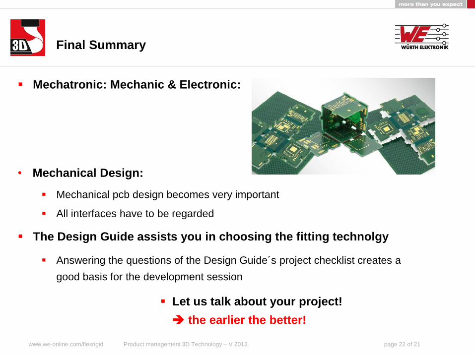
Final Summary
Mechatronic: Mechanic & Electronic:
• Mechanical Design:
Mechanical pcb design becomes very important
All interfaces have to be regarded
The Design Guide assists you in choosing the fitting technolgy
Answering the questions of the Design Guide´s project checklist creates a
good basis for the development session
Let us talk about your project!
the earlier the better!
www.we-online.com/flexrigid Product management 3D Technology – V 2013 page 22 of 21