YLPA0340SE-YLPA0495SE & YLPA0355HE-YLPA0505HE · YLPA0340SE-YLPA0495SE & YLPA0355HE-YLPA0505HE...
22
ENGINEERING GUIDE YLPA0340SE-YLPA0495SE & YLPA0355HE-YLPA0505HE Revision 0 FORM 150.68-EG1.EN.CE (1110) REVERSE CYCLE AIR TO WATER HEAT PUMPS WITH SCROLL COMPRESSORS STYLE A Cooling Capacities: 340 kW to 530 kW Heating Capacities: 350 kW to 555 kW R410A
Transcript of YLPA0340SE-YLPA0495SE & YLPA0355HE-YLPA0505HE · YLPA0340SE-YLPA0495SE & YLPA0355HE-YLPA0505HE...

ENGINEERING GUIDE
YLPA0340SE-YLPA0495SE & YLPA0355HE-YLPA0505HE
Revision 0 FORM 150.68-EG1.EN.CE (1110)
REVERSE CYCLE AIR TO WATER HEAT PUMPSWITH SCROLL COMPRESSORS
STYLE ACooling Capacities: 340 kW to 530 kW
Heating Capacities: 350 kW to 555 kW
R410A

2 EN
All data in this document is subject to change without prior notice.
Table of Contents
Nominal Data. ... ... ... ... ... ... ... ... ... ... ... ... 2
Specifi cation .. ... ... ... ... ... ... ... ... ... ... ... ... 3
Accessories and Options ... ... ... ... ... ... ... ... ... 4
Refrigerant Flow Block Diagrams ... ... ... ... ... ... 5
Component Location Diagrams ... ... ... ... ... ... ... 6
Application Data . ... ... ... ... ... ... ... ... ... ... ... 7
Pipework Arrangement . ... ... ... ... ... ... ... ... ... 9
Electrical Connection ... ... ... ... ... ... ... ... ... .. 10
Connection Diagram ... ... ... ... ... ... ... ... ... .. 12
Refrigerant to Water Heat Exchanger Pressure Drop Graph... ... ... ... ... ... ... ... ... ... ... ... ... ... .. 13
Nominal Data
YLPA Model 0340SE 0355HE 0415SE 0425HE 0495SE 0505HECapacity kW (1) 341 364 424 443 502 529
EER (2) 2.93 3.17 2.90 3.11 2.87 3.10
Eurovent Class B A C A C A
ESEER (3) 4.00 4.30 4.00 4.40 4.00 4.40
Capacity kW (4) 351 369 439 460 527 554
EER (4) 3.11 3.28 3.18 3.21 3.19 3.21
Eurovent Class B A B A B A
Sound Pressure at 10 Metres dB(A)(5) 57 57 57 57 57 58
(1) At 12/7°C leaving chilled water and 35°C ambient.
(2) Energy Efficiency Ratio at 12/7°C leaving chilled water and 35°C ambient.(3) ESEER is European Energy Efficiency Ratio. ESEER = 0.03A x 0.33B x 0.41C x 0.23D
A = EER is 100% capacity at 35°C ambient. B = EER is 75% capacity at 30°C ambient.
C = EER is 50% capacity at 25°C ambient. D = EER is 25% capacity at 20°C ambient.
(4) At 45°C leaving chilled water and 7°C ambient.(5) Sound Pressure according to Eurovent conditions. LS models
Cooling Mode
Heat Pump Mode
Operating Limitations ... ... ... ... ... ... ... ... ... .. 13
Fan Data ... ... ... ... ... ... ... ... ... ... ... ... ... .. 13
Physical Data. ... ... ... ... ... ... ... ... ... ... ... .. 14
Electrical Data ... ... ... ... ... ... ... ... ... ... ... .. 14
Dimensions - YLPA0340SE ... ... ... ... ... ... ... .. 15
Dimensions - YLPA0355HE ... ... ... ... ... ... ... .. 16
Dimensions - YLPA0415SE ... ... ... ... ... ... ... .. 17
Dimensions - YLPA0425HE ... ... ... ... ... ... ... .. 18
Dimensions - YLPA0495SE ... ... ... ... ... ... ... .. 19
Dimensions - YLPA0505HE ... ... ... ... ... ... ... .. 20

3EN
Specifi cation
YLPA air-to-water heat pumps are completely factory assembled with all interconnecting refrigerant piping and wiring ready for fi eld installation. The unit is pressure tested, evacuated, and fully factory charged with refrigerant R410A and oil in each of the independent refrigerant circuits. After assembly, an operational test is performed with water fl owing through the heat exchanger to ensure that each refrigerant circuit operates correctly.
The unit structure is manufactured from heavy-gauge, galvanised steel coated with baked-on powder paint (Champagne (RAL 7006, Munsell No. 9.8YR4.36/1.2)).
YLPA heat pumps are designed and manufactured within an EN ISO 9001 accredited organisation and in conformity with the following European Directives:
Machinery Directive (2006/42/EC)EMC Directive (2004/108/EC)Pressure Equipment Directive (97/23/EC)Safety Code for Mechanical Refrigeration (EN378-2 (2008))
Compressors
The unit has suction-cooled, hermetic scroll compressors. High effi ciency is achieved through a controlled orbit and the use of advanced scroll geometry. The compressors incorporate a compliant scroll design in both the axial and radial directions. All rotating parts are statically and dynamically balanced. The compressor motors have integral protection against overloads that will automatically reset. Starting is direct on line, and soft start is available as an option.
The compressors are switched On and Off by the unit microprocessor to provide capacity control. Each compressor is fi tted with a crankcase strap heater. All compressors are mounted on isolator pads to reduce transmission of vibration to the rest of the unit.
The motor terminal boxes have IP54 weather protection.
Refrigerant Circuits
Two independent refrigerant circuits are provided on each unit. Each circuit uses copper refrigerant pipe formed on computer controlled bending machines to reduce the number of brazed joints resulting in a reliable and leak resistant system.
Each circuit shall incorporate all components necessary for the designed operation including: a suction accumulator, a liquid receiver, a four way reversing valve, service valves, isolation (ball/angle) valves, pressure relief valves, a high absorption removable core fi lter-drier, a sight glass with moisture indicator, a cooling mode thermal expansion valve and a heat pump mode thermal expansion valve. Suction lines shall be covered with closed-cell insulation.
••••
Refrigerant to water heat exchanger
The 2-pass dual circuit shell and tube type direct expansion (DX) heat exchanger has refrigerant in the tubes and liquid fl owing through the baffl ed shell. The waterside (shell) design working pressure is 10.3 barg. The refrigerant side (tubes) design working pressure is 44.8 barg. The refrigerant side is protected by pressure relief valve(s).
The heat exchanger is equipped with a heater for frost protection to -29°C and insulated with fl exible closed-cell foam.
Water connection to the heat exchanger is via victaulic grooved connections. Victaulic fl ange connections are available as an option.
Ambient Coils
The ambient coils are seamless copper tubes, arranged in staggered rows, mechanically expanded into coated aluminium fi ns. Integral sub-cooling is included.
The condenser fans have metal ‘sickle’ blades integrated into the rotor of an external rotor motor. They are designed for maximum effi ciency and statically and dynamically balanced for vibration free operation. They are directly driven by independent motors, and positioned for vertical air discharge. The fan guards are constructed from heavy-gauge, corrosion resistant, coated steel.
The IP54 fan motors are the totally enclosed air-over type with permanently lubricated double-sealed ball bearings.
Power and Controls Panels
All power and controls are contained in an IP 55 cabinet with hinged and gasket sealed outer doors.
The power panel includes:A factory mounted non-fused disconnect switch with external red/yellow, lockable handle to enable connection of the unit power supply. The disconnect switch can be used to isolate the power for servicing and as a emergency stop.Factory mounted compressor contactors and compressor fuses provide short circuit protection. Overload protection for each compressor is provided by inherent motor winding temperature sensing and a trip module.Factory mounted fan contactors and fuses provide short circuit protection. Overload protection for each fan is provided by a inherent motor winding temperature device.Factory mounted control transformer to convert the unit supply voltage to 110 V - 1 Ø - 50 Hz for the control system.Control supply fuses and connections for a remote emergency stop device.
•
•
•
•
•

4 EN
The control panel includes:A Liquid Crystal Display (two display lines of twenty characters per line) with Light Emitting Diode backlighting for easy viewingA Colour coded 12-button keypadCustomer terminal blocks for control inputs and liquid fl ow switch.
Microprocessor Controls
The microprocessor control includes:Automatic control of compressor start/stop, anticoincidence and anti-recycle timers, pump and unit alarm contacts. Automatic reset to normal unit operation after power failure.Remote water temperature setpoint reset via analog input or a pulse width modulated (PWM) input signal or up to two steps of demand (load) limiting.Software is loaded into the microprocessor controller via a SD card, with programmed setpoints retained in a lithium battery backed real time clock (RTC) memory.Forty character liquid crystal display, with description available in fi ve languages (English, French, German, Spanish or Italian).
Programmable setpoints:Chilled liquid temperature setpoint and rangeHot liquid temperature setpoint and rangeRemote reset temperature rangeSet daily schedule/holiday for start/stopManual override for servicingLow ambient cutoutHigh ambient cutout (heating only - fi xed)Low liquid temperature cutoutLow suction pressure cutoutHigh discharge pressure cutoutAnti-recycle timer (compressor start cycle time)Anti-coincident timer (delay compressor starts)
Displayed Data:Leaving liquid temperature Air coil defrost temperaturesLow leaving liquid temperature cutout settingLow ambient temperature cutout settingAmbient air temperatureMetric or Imperial dataDischarge and suction pressure cutout settingsSystem discharge and suction pressuresAnti-recycle timer status for each systemAnti-coincident system start timer conditionCompressor run statusNo load conditionDay, date and timeDaily start/stop timesHoliday statusAutomatic or manual system lead/lag control
•
••
•
•
•
•
••••••••••••
••••••••••••••••
Lead system defi nitionCompressor starts & operating hours (each compressor)Status of evaporator heater and fan operationRun permissive statusNumber of compressors runningMode solenoid valve statusLoad & unload timer statusLiquid pump status
System Safeties:Cause individual compressors to perform auto shut down and require manual reset in the event of 3 trips in a 90-minute time periodHigh discharge pressureLow suction pressureHigh-pressure switchesMotor protector
Unit Safeties:
They are automatic reset and cause compressor to shut down
Low leaving chilled liquid temperatureUnder voltageLoss of liquid fl ow (through fl ow switch)
For each system a common alarm contact for:Low leaving chilled liquid temperatureLow voltageLow batteryHigh discharge pressure (per system)Low suction pressure (per system)Compressor motor protection
Accessories and Options
Power Factor Correction
Factory mounted passive (static) power factor correction capacitors to correct unit compressor power factors to a target of 0.9 (depending on operating conditions). Option not available on compressors fi tted with soft start option.Soft Starters
Factory mounted soft starters reduce the inrush current to the last compressor on each refrigerant circuit. They are preset so that no fi eld adjustment is required. Language LCD and Keypad
English, French, German, Italian, Spanish and Chinese (Simplifi ed) unit LCD read out and keypad available. Standard Language is English.
Dual speed fans
Fans operate either in high mode (920 RPM) or in low mode (670 RPM). Fan speed reduces automatically from high to low mode as head pressure falls, or at programmed times within the control software.
••
••••••
•
••••
•••
••••••

5EN
High Ambient KitDouble skinned control panel, to offset solar heat, should be selected for all units operating in ambients greater than 46°C. Language LCD and Keypad
English, French, German, Italian and Spanish unit LCD read out and keypad available. Standard Language is English.38 mm Evaporator Insulation
Double thickness insulation provided for enhanced effi ciency, and low temperature applications.
Flow Switch
Vapour Proof, paddle-type with 1’’NPT connection for upright mounting in horizontal pipe. This fl ow switch or its equivalent must be supplied with each unit to protect the evaporator from loss of liquid fl ow (Field Mounted)Neoprene Pads Isolators
Recommended for normal installations (Field mounted)25 mm Spring Isolators
Level adjustable, spring and cage type isolators for mounting under the unit base rails (Field mounted).Lifting Lug Kit
One set of ISO MK5 camlocs to enable safe and easy unit handling.
Refrigerant Flow Block Diagrams
Cooling and Defrost Modes
Low pressure liquid refrigerant enters the heat exchanger and is evaporated and superheated by the heat energy absorbed from the chilled liquid. Low pressure vapour enters the compressor, via the four-way reversing valve and accumulator, where pressure and superheat are increased. The high pressure vapour is fed to the ambient coils and fans, via the four way reversing valve, where heat is removed. The fully condensed and subcooled liquid passes through the expansion valve (cooling) where pressure is reduced and further cooling takes place before returning to the heat exchanger.
6 EN
Heat Pump Mode
Liquid refrigerant enters the ambient coil and is fully evaporated and superheated by the energy absorbed from the ambient air. Low-pressure superheated refrigerant vapour passes through the four-way reversing valve and the accumulator and enters the compressor, where pressure and superheat are increased. High-pressure superheated refrigerant vapour enters the refrigerant to water plate heat exchanger where heat is rejected to the water. The high-pressure liquid refrigerant, leaving the heat exchanger passes through the liquid receiver and enters thermostatic expansion valve (heating) where the refrigerant pressure is reduced and subsequently cooled before returning to the ambient coil.
Defrost
When ice builds up on the ambient coils defrost is initiated by operating the machine in a cooling mode. Each of the two refrigerant circuits will be defrosted one at a time. When defrost is operative the circuit operating in heat pump mode is in balance with the circuit operating in defrost (cooling). Therefore, heat energy is not removed from the hot water system.
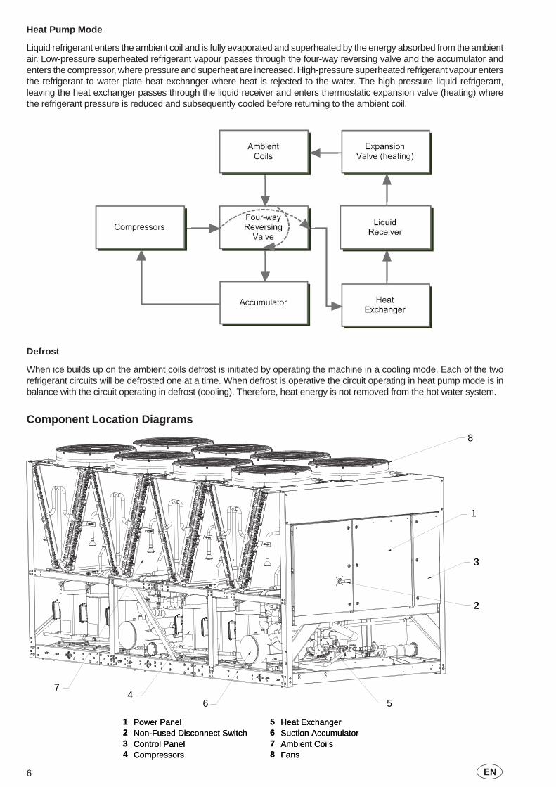
Component Location Diagrams
1
2
3
8
54
67
1
2
3
8
54
67
1 Power Panel 5 Heat Exchanger2 Non-Fused Disconnect Switch 6 Suction Accumulator3 Control Panel 7 Ambient Coils4 Compressors 8 Fans
1 Power Panel 5 Heat Exchanger2 Non-Fused Disconnect Switch 6 Suction Accumulator3 Control Panel 7 Ambient Coils4 Compressors 8 Fans
7EN
Application Data
Location Requirements
To achieve optimum performance and trouble-free service, it is essential that the proposed installation site meet with the location and space requirements for the model being installed.
The clearances recommended are nominal for the safe and effi cient operation and maintenance of the unit and power and control panels. Local Health and safety regulations, or practical considerations for service replacement of large components, may require larger clearances than those given in this manual.
Outdoor installations
The units can be installed at ground level on a suitable at level foundation easily capable of supporting the weight of the unit, or on a suitable rooftop location. In both cases an adequate supply of air is required. Avoid locations where the sound output and air discharge from the unit may be objectionable.
The location should be selected for minimum sun exposure and away from boiler fl ues and other sources of airborne chemicals that could attack the condenser coils and steel parts of the unit.
If located in an area accessible to unauthorized persons, steps must be taken to prevent access to the unit by means of a protective fence. This will help to prevent the possibility of vandalism, accidental damage, or possible harm caused by unauthorized removal of protective guards or opening panels to expose rotating or electrically live components.
For ground level locations, the unit must be installed on a suitable fl at and level concrete base that extends to fully support the two side channels of the unit base frame. A one-piece concrete slab, with footings extending below the frost line is recommended. To avoid noise and vibration transmission, the unit should not be secured to the building foundation.
On rooftop locations, choose a place with adequate structural strength to safely support the entire operating weight of the unit and service personnel. The unit can be mounted on a concrete slab, similar to ground fl oor locations, or on steel channels of suitable strength. The channels should be spaced with the same centres as the unit side and front base rails. This will allow vibration isolators to be fi tted if required. Isolators are recommended for rooftop locations.
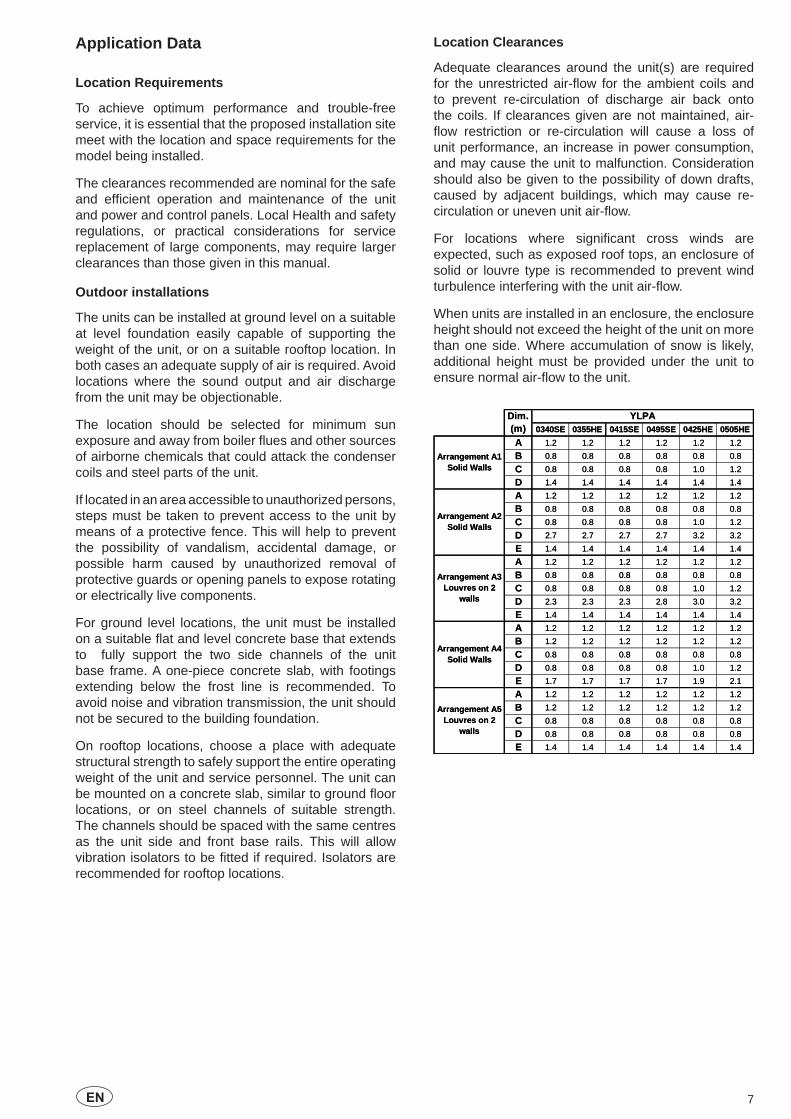
Location Clearances
Adequate clearances around the unit(s) are required for the unrestricted air-fl ow for the ambient coils and to prevent re-circulation of discharge air back onto the coils. If clearances given are not maintained, air-fl ow restriction or re-circulation will cause a loss of unit performance, an increase in power consumption, and may cause the unit to malfunction. Consideration should also be given to the possibility of down drafts, caused by adjacent buildings, which may cause re-circulation or uneven unit air-fl ow.
For locations where signifi cant cross winds are expected, such as exposed roof tops, an enclosure of solid or louvre type is recommended to prevent wind turbulence interfering with the unit air-fl ow.
When units are installed in an enclosure, the enclosure height should not exceed the height of the unit on more than one side. Where accumulation of snow is likely, additional height must be provided under the unit to ensure normal air-fl ow to the unit.
0340SE 0355HE 0415SE 0495SE 0425HE 0505HEA 1.2 1.2 1.2 1.2 1.2 1.2
B 0.8 0.8 0.8 0.8 0.8 0.8
C 0.8 0.8 0.8 0.8 1.0 1.2
D 1.4 1.4 1.4 1.4 1.4 1.4
A 1.2 1.2 1.2 1.2 1.2 1.2
B 0.8 0.8 0.8 0.8 0.8 0.8
C 0.8 0.8 0.8 0.8 1.0 1.2
D 2.7 2.7 2.7 2.7 3.2 3.2
E 1.4 1.4 1.4 1.4 1.4 1.4
A 1.2 1.2 1.2 1.2 1.2 1.2
B 0.8 0.8 0.8 0.8 0.8 0.8
C 0.8 0.8 0.8 0.8 1.0 1.2
D 2.3 2.3 2.3 2.8 3.0 3.2
E 1.4 1.4 1.4 1.4 1.4 1.4
A 1.2 1.2 1.2 1.2 1.2 1.2
B 1.2 1.2 1.2 1.2 1.2 1.2
C 0.8 0.8 0.8 0.8 0.8 0.8
D 0.8 0.8 0.8 0.8 1.0 1.2
E 1.7 1.7 1.7 1.7 1.9 2.1
A 1.2 1.2 1.2 1.2 1.2 1.2
B 1.2 1.2 1.2 1.2 1.2 1.2
C 0.8 0.8 0.8 0.8 0.8 0.8
D 0.8 0.8 0.8 0.8 0.8 0.8
E 1.4 1.4 1.4 1.4 1.4 1.4
Arrangement A5Louvres on 2
walls
Dim.(m)
YLPA
Arrangement A1Solid Walls
Arrangement A2Solid Walls
Arrangement A3Louvres on 2
walls
Arrangement A4Solid Walls
8 EN
A1
A
B
C
DE
A1
C
C
D
D
E
A
B
CD
A1
A4
A
A
B
B
A2
A3
A5
A
B
CDE
E

9EN
Installation of Vibration Isolators
An optional set of vibration isolators can be supplied loose with each unit.
Pipework Connection
The following piping recommendations are intended to ensure satisfactory operation of the unit. Failure to follow these recommendations could cause damage to the unit, or loss of performance, and may invalidate the warranty.
A fl ow switch must be installed in the customer pipework at the outlet of the evaporator as shown in the arrangement diagrams, and wired back to the control panel using screened cable. This is to prevent damage to the evaporator caused by inadequate liquid fl ow. To prevent turbulent fl ow, there must be straight pipework either side of the fl ow switch equal in length to at least 5 times the diameter of the pipe.
The fl ow switches used must have gold plated contacts for low voltage/current operation
The liquid pumps installed in the pipework systems should discharge directly into the unit heat exchanger sections of the system. The pumps require an auto-starter (by others) to be wired to the control panel.
Pipework and fi ttings must be separately supported to prevent any loading on the heat exchanger(s). Flexible connections are recommended which will also minimize transmission of vibrations to the building. Flexible connections must be used if the unit is mounted on anti-vibration mounts as some movement of the unit can be expected in normal operation.
Pipework and fi ttings immediately next to the heat exchanger(s) should be readily demountable to enable cleaning prior to operation, and to facilitate visual inspection of the exchanger nozzles.
Each heat exchanger must be protected by a strainer, preferably of 20 mesh, fi tted as close as possible to the liquid inlet connection, and provided with a means of local isolation.
The heat exchanger(s) must not be exposed to fl ushing velocities or debris released during fl ushing. It is recommended that a suitably sized by-pass and valve arrangement be installed to allow fl ushing of the pipework system. The by-pass can be used during maintenance to isolate the heat exchanger(s) without disrupting fl ow to other units.
Thermometer and pressure gauge connections should be provided on the inlet and outlet connections of each heat exchanger.
Drain and air vent connections should be provided at all low and high points in the pipework to permit drainage of the system, and to vent any air in the pipes.
Liquid systems at risk of freezing, due to low ambient temperatures, should be protected using insulation and heater tape and/or a suitable glycol solution. The liquid pumps must also be used to ensure liquid is circulated when the ambient temperature approaches freezing point. Insulation should also be installed around the heat exchanger nozzles.
Heater tape of 21 W/m under the insulation is recommended, supplied independantly and controlled by an ambient temperature thermostat set to switch on at approximately 2.2ºC above the freezing temperature of the chilled liquid.
The heat excanger is protected by a heater mat placed under the insulation, which are powered from the unit control system power supply. During cold weather when there is a risk of freezing, chiller power should be left switched on to provide the freeze protection function unless the liquid systems have been drained.
Pipework Arrangement
The following are suggested pipework arrangements for single unit installations. For multiple unit installations, each unit should be piped as shown. These are recommendations of the Building Services Research Association.
Isolating Valve – Normally Closed
Flow Regulating Valve
Strainer
Pressure Tapping
Air vent
Flow Switch
Isolating Valve – Normally Open

10 EN
Connection Types and Sizes
Standard pipework connections are of the Victaulic groove type.
For connection sizes relevant to individual models refer to the physical data tables in this manual.
Water Treatment
The unit performance given in the Design Guide is based on a fouling factor of 0.018 m² °C/kW. Dirt, scale, grease and certain types of water treatment will adversely affect the heat exchanger surfaces and therefore unit performance. Foreign matter in the water system(s) can increase the pressure drop, reducing the fl ow rate and causing potential damage.
Aerated, brackish or salt water is not recommended for use in the water systems. JCI recommends that a water treatment specialist be consulted to determine whether the proposed water composition will not affect the heat exchanger materials of carbon steel and copper. The pH value of the water fl owing through the unit must be kept between 7 and 8.5.
Refrigerant Relief Valve Piping
The heat exchanger is protected against internal refrigerant overpressure by refrigerant relief valves. A pressure relief valve is mounted on each of the main refrigerant lines connecting the evaporator to the compressors.
For indoor installations, pressure relief valves should be piped to the exterior of the building.
The size of any pipework attached to a relief valve must be of suffi cient diameter so as not to cause resistance to the operation of the valve. For critical or complex installations refer to EN13136.
Unless otherwise specifi ed by local regulations, the internal diameter depends on the length of pipe required and can be estimated with the following formula:
D5=1.447 x L
Where:D = minimum pipe internal diameter (cm)L = length of pipe (m).
If relief pipework is common to more than one valve its cross sectional area must be at least the total required by each valve. Valve types should not be mixed on a common pipe. Precautions should be taken to ensure that the exit of relief valves/vent pipe remain clear of obstructions at all times.
Electrical Connection
The following connection recommendations are intended to ensure safe and satisfactory operation of the unit. Failure to follow these recommendations could cause harm to persons, or damage to the unit, and may invalidate the warranty.
No additional controls (relays, etc.) should be mounted in the control panel. Power and control wiring not connected to the control panel should not be run through the control panel. If these precautions are not followed it could lead to a risk of electrocution. In addition, electrical noise could cause malfunctions or damage the unit and its controls.
Power Wiring
These units are suitable for 400 V, 3-phase, 50Hz nominal supplies only.
All electrical wiring should be carried out in accordance with local regulations. Route properly sized cables to the cable entries in the bottom of the power panel.
In accordance with EN 60204 it is the responsibility of the user to install over current protection devices between the supply conductors and the power supply terminals on the unit.
To ensure that no eddy currents are set up in the power panel, the cables forming each 3 phase power supply must enter via the same cable entry.
All sources of supply to the unit must be taken via a common point of isolation (not supplied by JCI).
Single Point Power Supply Wiring
All models require one fi eld provided 400 V, 3Ø, 50 Hz + PE (Protected Earth) supply to the unit with circuit protection.
Connect the 3-phase supply to the non-fused disconnect switch located in the power panel using M12 lugs.
Connect the earth wire to the main protective earth terminal located in the power panel using a M10 lug.
Control Circuit Transformer
The control circuit transformer (400 V, 2Ø, 50 Hz) providing the 110 V, 1Ø, 50 Hz supply to the unit control system is fi tted in a separate enclosure.
Remote Emergency Stop Device
If required, a remote emergency stop device may be wired into the unit. This device should be rated at 20 amps, 110 V, AC-15. The device should be wired into terminals L and 5 in the power panel after removing the factory fi tted link.

11EN
Control Wiring - Voltage Free Contact
All wiring to the voltage free contact terminal block requires a supply provided by the customer maximum voltage 254 Vac, 28 Vdc.
The customer must take particular care deriving the supplies for the voltage free terminals with regard to a common point of isolation. Thus, these circuits when used must be fed via the common point of isolation so the voltage to these circuits is removed when the common point of isolation to the unit is opened. This common point of isolation is not supplied by JCI.
In accordance with EN 60204 it is recommended that the customer wiring to these terminals uses orange wires. This will ensure that circuits not switched off by the units supply disconnecting device are distinguished by colour, so that they can easily be identifi ed as live even when the unit disconnecting devices are off. The YORK voltage free contacts are rated at 125 VA.
All inductive devices (relays) switched by the YORK voltage free contacts must have their coil suppressed using standard RC suppressors. If these precautions are not followed, electrical noise could cause malfunctions or damage to the unit and its controls.
Chilled Liquid Pump Starter
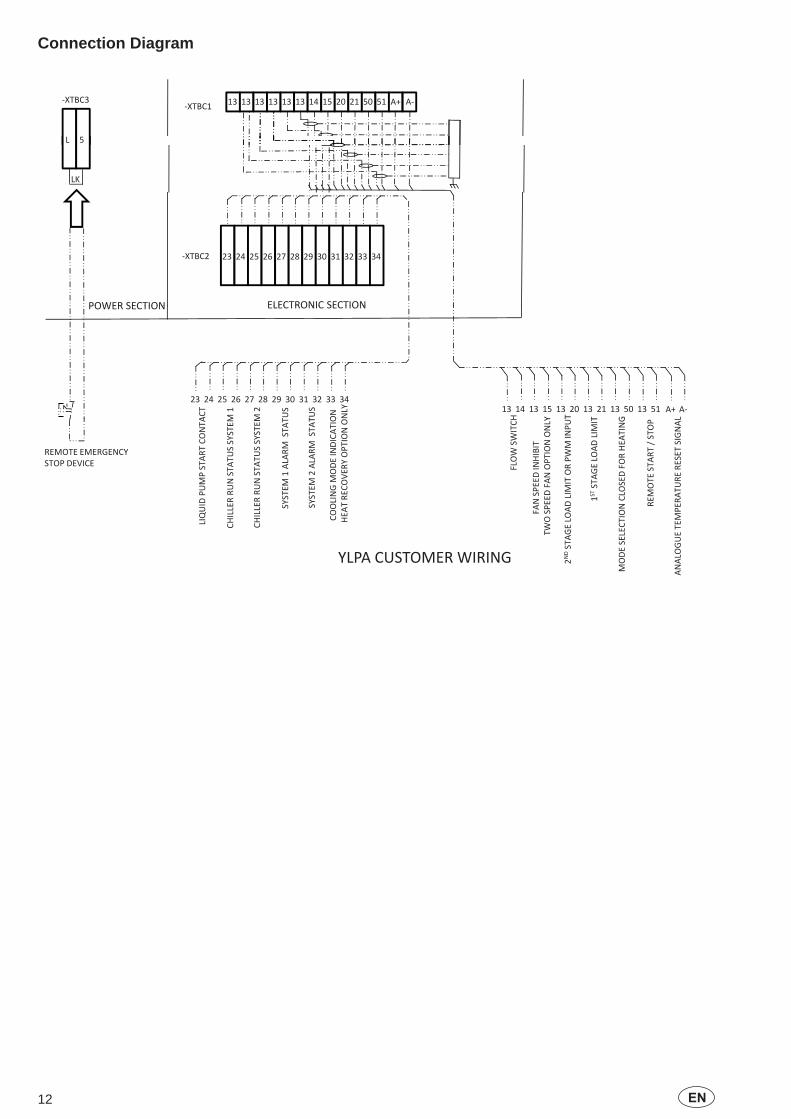
Terminals 23 and 24 close to start the liquid pump. This contact is closed if there is a ‘Leaving Liquid Temperature Cutout’ or any of the compressors are running or the daily schedule is not calling for a shutdown with the unit switch on.
The contact must be used to ensure that the pump is running in the event of a ‘Leaving Liquid Temperature Cutout’.
The pump contact will not close to run the pump if the unit has been powered up for less than 30 seconds, or if the pump has run in the last 30 seconds, to prevent pump motor overheating.
Run Contacts
Terminals 25 and 26 close to indicate that refrigerant system 1 is running and terminals 27 and 28 close to indicate that refrigerant system 2 is running.
Alarm Contacts
Each refrigerant system has a voltage-free normally open contact that will close when control power is applied to the panel, if no fault conditions are present. When a fault occurs which locks a system out, or there is a power failure the contact opens. To obtain a system alarm signal, connect the alarm circuit to terminals 29 and 30 for No. 1 system and terminals 31 and 32 for No. 2 system.
Control Wiring - System Inputs
All wiring to the control terminal block (nominal 30 Vdc) must be run in screened cable, with the screen earthed at the panel end only. Run screened cable separately from mains cable to avoid electrical noise pick-up.
The voltage free contacts must be suitable for 30 Vdc (gold contacts recommended). If the voltage free contacts form part of a relay or contactor, the coil of the device must be suppressed using a standard RC suppressor. The above precautions must be taken to avoid electrical noise that could cause a malfunction or damage to the unit and its controls.
Flow Switch
A chilled liquid fl ow switch of suitable type must be connected to terminals 13 and 14 to provide adequate protection against loss of liquid fl ow.
Remote Start/Stop
Connect a remote switch to terminals 13 and 51 to provide remote start/stop control if required.
Remote Mode Selection
Remote mode selection can be accomplished by connecting a contact between terminals 13 and 50. With the contact open the unit is in the cooling mode, with the contact closed the unit is in the heating mode.
Remote Reset of Chilled Liquid Setpoint
The PWM input (terminals 13 and 20) allows reset of the chilled liquid setpoint by supplying a ‘timed’ contact closure.
Remote Load Limiting
Load limiting prevents the unit from loading beyond a desired value. The unit % load limit depends on the number of compressors on the unit. The load limit inputs to terminals 13 and 21 work in conjunction with the PWM input to terminals 13 and 20.
Fan Full Speed Inhibit
To reduce unit noise the fans can be limited to run at a maximum step of all fans in star (reduced speed) i.e. fan full speed is inhibited. Connect a customer voltage free contact to terminals 13 & 15.
EMS Analogue Input
Provides a means of resetting the leaving chilled or hot liquid temperature from the BAS/EMS. Accepts 4 to 20 mA, 0 to 20 mA, 0 to 10 Vdc or 2-10 Vdc. Connect to terminal A+ and A-.
Modbus, BACnet MS/TP and N2
Enable communications with building protocol systems using Modbus, BACnet or N2 protocol. Connect through standard RS485 port.
12 EN
Connection Diagram
13 13 13 13 13 14 1513 20 21 50 51 A+A-A+-XTBC3-XTBC1
L 5
LK
23 24 25 26 27 28 29 30 31 32 33 34-XTBC2
ELECTRONIC SECTIONPOWER SECTION ELECTRONIC SECTIONPOWER SECTION
M1
M2
TUS
TUS
ACT
23 24 25 26 27 28 29 30 31 32 33 34
ON NLY
H Y GTT L
13 14 13 15 13 20 13 21 13 50 13 51 A+ A-
STATU
SSYSTEM
STATU
SSYSTEM
1ALARM
STAT
2ALARM
STAT
PSTART
CONTA
ODEINDICATIO
VERY
OPTIONO
ESTART
/STOP
FLOW
SWITC H
DINHIBIT
NOPTIONONLY
DFO
RHEA
TING
AGELO
ADLIMIT
ORPW
MINPU
T
ERE
SETSIGNAL
REMOTE EMERGENCYSTOP DEVICE
CHILLERRU
NS
CHILLERRU
NS
SYSTEM
1
SYSTEM
LIQUID
PUMP
COOLINGM
HEA
TRE
COV
REMOTE
FANSPEED
TWOSPEEDFA
N
ECTIONCLOSED
1STSTA
GELO
ADLIMIT
TEMPERA
TURE
T
MODESEL
2NDSTAG
ANALO
GUE
YLPA CUSTOMER WIRING
13EN
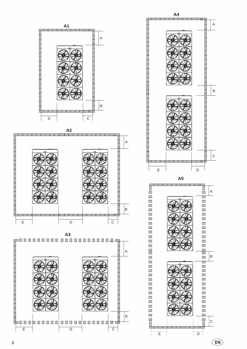
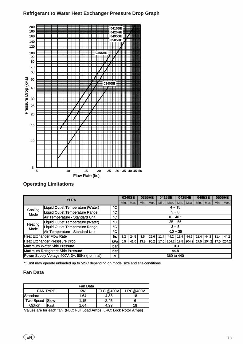
Refrigerant to Water Heat Exchanger Pressure Drop Graph
Operating Limitations
Fan Data
10 15 20 25 30 40 50
10
15
20
25
30
40
50
60708090
100
120140
160180200
Flow Rate (l/s)
Pre
ssur
e D
rop
(kP
a)
35 455
5
0415SE0425HE0495SE0505HE
0340SE
0355HE
10 15 20 25 30 40 50
10
15
20
25
30
40
50
60708090
100
120140
160180200
Flow Rate (l/s)
Pre
ssur
e D
rop
(kP
a)
35 455
5
0415SE0425HE0495SE0505HE
0340SE
0355HE
Min. Max. Min. Max. Min. Max. Min. Max. Min. Max. Min. Max.
Liquid Outlet Temperature (Water) °CLiquid Outlet Temperature Range °CAir Temperature - Standard Unit °CLiquid Outlet Temperature (Water) °CLiquid Outlet Temperature Range °CAir Temperature - Standard Unit °C
l/s 8.2 24.5 8.5 25.6 11.4 44.2 11.4 44.2 11.4 44.2 11.4 44.2
kPa 6.5 41.0 13.8 95.2 17.5 204.2 17.5 204.2 17.5 204.2 17.5 204.2
barbarV
*: Unit may operate unloaded up to 52ºC depending on model size and site conditions.
3 ~ 8
Maximum Water Side Pressure
Heating Mode
Heat Exchanger Flow RateHeat Exchanger Presssure Drop
-10 ~ 35
35 ~ 55
0340SEYLPA 0415SE 0425HE 0495SE 0505HE
Power Supply Voltage 400V, 3~, 50Hz (nominal)
10.344.8
360 to 440Maximum Refrigerant Side Pressure
0355HE
4 ~ 153 ~ 8
0 ~ 46 *
Cooling Mode
KW FLC @400V [email protected] 4.33 18
Slow 1.15 2.45 6Fast 1.64 4.33 18
Values are for each fan. (FLC: Full Load Amps; LRC: Lock Rotor Amps)
Fan DataFAN TYPE
StandardTwo Speed
Option
KW FLC @400V [email protected] 4.33 18
Slow 1.15 2.45 6Fast 1.64 4.33 18
Values are for each fan. (FLC: Full Load Amps; LRC: Lock Rotor Amps)
Fan DataFAN TYPE
StandardTwo Speed
Option

14 EN
Physical Data
Electrical Data
0340SE 0355HE 0415SE 0425HE 0495SE 0505HENumber of refrigerant circuitsRefrigerant Charge (1) Circuit 1 / Circuit 2 kg 46/48 59/62 68/50 82/60 68/68 82/82Oil Charge Circuit 1 / Circuit 2 l 11/11 11/11 17/11 17/11 17/17 17/17
Number of compressors 2 / 2 2 / 2 3 / 2 3 / 2 3 / 3 3 / 3TypeNumberTypeWater Volume l 200 250Water Connections InchNumber of Fans (circuit 1 / circuit 2) 3 / 3 4 / 4 4 / 3 6 / 4 4 / 4 6 / 6Total Air Flow - Standard Models m3/s 35 47 41 58 47 70Length mm 4937 4937 4937 5854 4937 6971Width mm 2246 2246 2246 2246 2246 2246Height mm 2391 2391 2391 2391 2391 2391Shipping Weight kg 4400 4500 4700 5100 4900 5800Operating Weight kg 4600 4750 5000 5400 5200 6100
(1) Liquid sub-cooling measured at the liquid line should be between 8.5 and 11.0°C at circuit full load. Sub-cooling is determined by the level of refrigerant charge in each system
Ambient Coils Fans
Dimensions
Basic Unit Weight
YLPA
Compressor
Refrigerant to Water Heat Exchanger
8
2
Scroll
300
1Shell and Tubes
Nominal Running
ConditionsAmps
@ 400 VAmps@400V
Amps@ 360V
Direct on Line (1) Soft Start (1)
Standard 198 238 247 465 350PF 189 229 241 458 -
PF & SS 194 233 244 - 346Standard 207 246 255 474 359
PF 198 238 250 467 -PF & SS 202 242 253 - 354Standard 246 295 306 513 398
PF 234 284 299 504 -PF & SS 239 289 302 - 391Standard 259 308 319 526 411
PF 247 297 312 517 -PF & SS 252 302 315 - 404Standard 293 352 366 560 445
PF 279 339 357 549 -PF & SS 284 344 360 - 436Standard 311 369 383 577 462
PF 297 357 375 566 -PF & SS 301 361 378 - 453
PF = Power Factor OptionPF & SS = Power Factor and Soft Start Option(1) Start up amps is the largest compressor starting with all other compressors/fans operating at nominal conditions at 400V.
0505HE
0340SE
0355HE
0415SE
0425HE
0495SE
YLPA
Maximum RunningConditions
Start upAmps
Unit Data (Using Standard Fans or Two speed Optional Fans at Full Speed)Nominal Running
ConditionsAmps
@ 400 VAmps@400V
Amps@ 360V
Direct on Line (1) Soft Start (1)
Standard 198 238 247 465 350PF 189 229 241 458 -
PF & SS 194 233 244 - 346Standard 207 246 255 474 359
PF 198 238 250 467 -PF & SS 202 242 253 - 354Standard 246 295 306 513 398
PF 234 284 299 504 -PF & SS 239 289 302 - 391Standard 259 308 319 526 411
PF 247 297 312 517 -PF & SS 252 302 315 - 404Standard 293 352 366 560 445
PF 279 339 357 549 -PF & SS 284 344 360 - 436Standard 311 369 383 577 462
PF 297 357 375 566 -PF & SS 301 361 378 - 453
PF = Power Factor OptionPF & SS = Power Factor and Soft Start Option(1) Start up amps is the largest compressor starting with all other compressors/fans operating at nominal conditions at 400V.
0505HE
0340SE
0355HE
0415SE
0425HE
0495SE
YLPA
Maximum RunningConditions
Start upAmps
Unit Data (Using Standard Fans or Two speed Optional Fans at Full Speed)

15EN
Dimensions - YLPA0340SE
6
54
32
111
6
54
32
111
1D
ista
nce
betw
een
anti
vibr
atio
n m
ount
s4
Wat
er in
let c
onne
ctio
n to
hea
t exc
hang
er -
DN
200
wel
ded
flang
e
2P
ower
cab
le e
ntry
via
gla
nd p
late
5W
ater
out
let c
onne
ctio
n to
hea
t exc
hang
er -
DN
200
wel
ded
flang
e3
Con
trol
cab
le e
ntry

16 EN
Dimensions - YLPA0355HE
6
45
11
1
32
6
45
11
1
32
1D
ista
nce
betw
een
anti
vibr
atio
n m
ount
s4
Wat
er in
let c
onne
ctio
n to
hea
t exc
hang
er -
DN
200
wel
ded
flang
e
2P
ower
cab
le e
ntry
via
gla
nd p
late
5W
ater
out
let c
onne
ctio
n to
hea
t exc
hang
er -
DN
200
wel
ded
flang
e3
Con
trol
cab
le e
ntry

17EN
Dimensions - YLPA0415SE
32
4
111
56
32
4
111
56
1D
ista
nce
betw
een
anti
vibr
atio
n m
ount
s4
Wat
er in
let c
onne
ctio
n to
hea
t exc
hang
er -
DN
200
wel
ded
flang
e
2P
ower
cab
le e
ntry
via
gla
nd p
late
5W
ater
out
let c
onne
ctio
n to
hea
t exc
hang
er -
DN
200
wel
ded
flang
e3
Con
trol
cab
le e
ntry

18 EN
Dimensions - YLPA0425HE
6
5
4
32
11
11
1
6
5
4
32
11
11
1
1D
ista
nce
betw
een
anti
vibr
atio
n m
ount
s4
Wat
er in
let c
onne
ctio
n to
hea
t exc
hang
er -
DN
200
wel
ded
flang
e
2P
ower
cab
le e
ntry
via
gla
nd p
late
5W
ater
out
let c
onne
ctio
n to
hea
t exc
hang
er -
DN
200
wel
ded
flang
e3
Con
trol
cab
le e
ntry
19EN
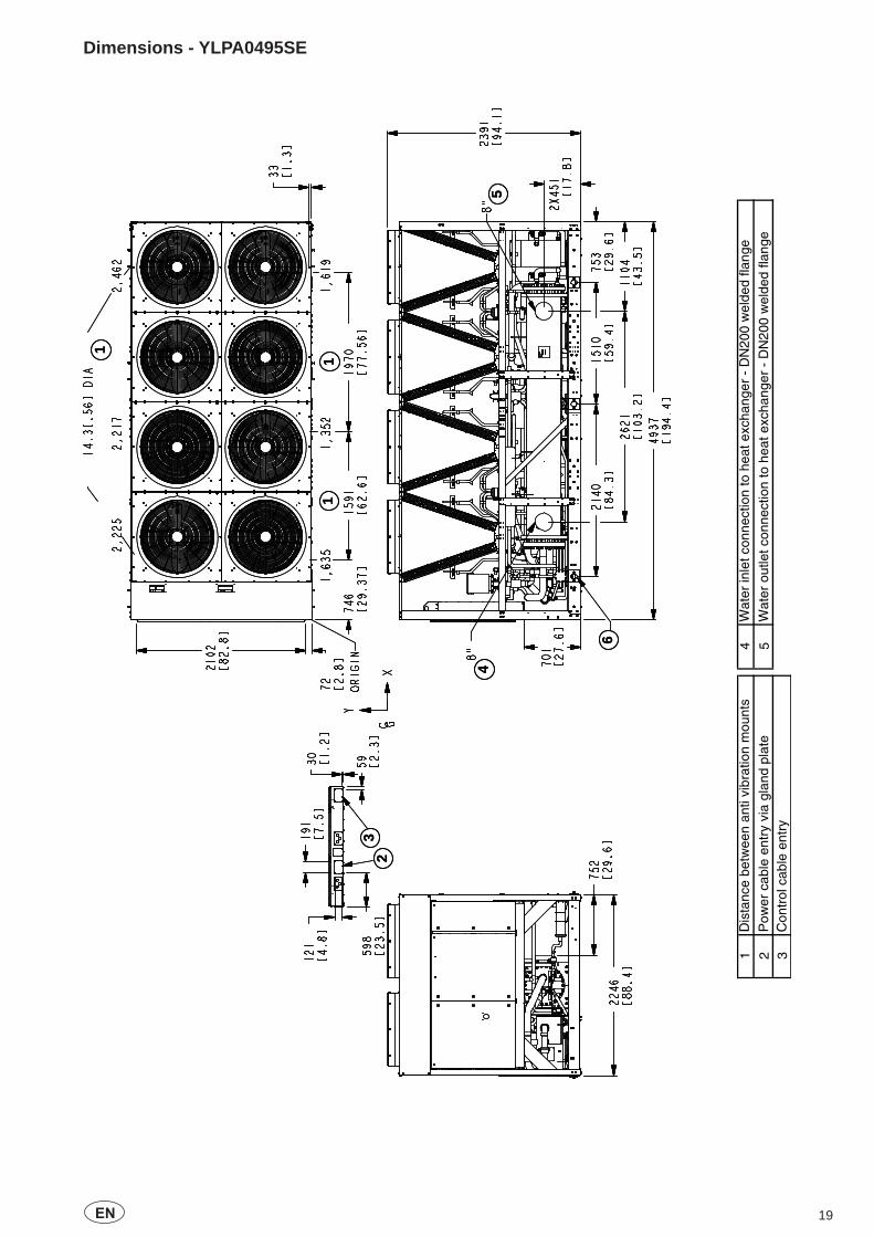
Dimensions - YLPA0495SE
23
1
11
45
6
23
1
11
45
6
1D
ista
nce
betw
een
anti
vibr
atio
n m
ount
s4
Wat
er in
let c
onne
ctio
n to
hea
t exc
hang
er -
DN
200
wel
ded
flang
e
2P
ower
cab
le e
ntry
via
gla
nd p
late
5W
ater
out
let c
onne
ctio
n to
hea
t exc
hang
er -
DN
200
wel
ded
flang
e3
Con
trol
cab
le e
ntry

20 EN
Dimensions - YLPA0505HE
6
5
4
1
11
1
23
6
5
4
1
11
1
23
1D
ista
nce
betw
een
anti
vibr
atio
n m
ount
s4
Wat
er in
let c
onne
ctio
n to
hea
t exc
hang
er -
DN
200
wel
ded
flang
e
2P
ower
cab
le e
ntry
via
gla
nd p
late
5W
ater
out
let c
onne
ctio
n to
hea
t exc
hang
er -
DN
200
wel
ded
flang
e3
Con
trol
cab
le e
ntry

21EN

Form 150.68-EG1.EN.CE (1110) Subject to change without notice. ALL RIGHTS RESERVED
www.johnsoncontrols.com