Year 1 Annual Report – Volume 2 - PBworks
107
Transcript of Year 1 Annual Report – Volume 2 - PBworks


Year 1 Annual Report – Volume 2
ii
COE CST YEAR 1 ANNUAL REPORT This report is produced by the FAA Office of Commercial Space Transportation in fulfillment of FAA Centers of Excellence program requirements.
This report is broken into three volumes:
Volume 1 gives a description of the FAA COE CST, its research, structure, member universities and research tasks.
Volume 2 is a comprehensive set of presentation charts of each research task as presented at the first Annual Technical Meeting in November 2011.
Volume 3 is a comprehensive set of notes from all FAA COE CST teleconferences and face-to-face meetings.
Any questions or comments about the content of this report should be directed to Mr. Ken Davidian, FAA COE CST Program Manager or Dr. Patricia Watts, FAA COE Program Director.

1
Federal AviationAdministration 1
COE CST First Annual Technical Meeting (ATM1)November 9 & 10, 2011
COE CST First Annual Technical Meeting:
1. Physiologic Database Definition & Design
James Vanderploeg, MD
November 10, 2011
Federal AviationAdministration
Federal AviationAdministration 2
COE CST First Annual Technical Meeting November 9 & 10, 2011
Overview• Team Members
• Purpose of Task
• Schedule & Milestones
• Next Steps
• Contact Information
Federal AviationAdministration 3
COE CST First Annual Technical Meeting November 9 & 10, 2011
Team Members • UTMB
• PI: Jim Vanderploeg, MD (UTMB Aerospace Med.)
• Student: Jennifer Law, MD (UTMB Aerospace Med.)
• Student: Charles Mathers, MD (UTMB Aerosp. Med.)
• Co-I: Richard Jennings, MD (UTMB Aerospace Med)
• NASA Johnson Space Center• Mary Van Baalen
• Dr. John Charles
• Dr. Jeffrey Davis
• Wyle Integrated Science & Engineering• Eric Kerstman, MD
• Christine Smith
• FAA CAMI• Dr. Melchor Antunano
Federal AviationAdministration 4
COE CST First Annual Technical Meeting November 9 & 10, 2011
Height
Visual Acuity
Arm Reach
Gender
Native Language
Strength
Endurance
Mechanical Aptitude
Reaction Time (Scan Pattern)
Cultural Differences
Susceptibility to SAS
Operational Background
Underlying Medical
Conditions
Weight
Situational Awareness
Depth of Knowledge
(Preparedness)
Auditory Acuity
Verbal Clarity & Fluency
G-TolerancePain
(Discomfort) Tolerance
Understanding Human Complexity

2
Federal AviationAdministration 5
COE CST First Annual Technical Meeting November 9 & 10, 2011
Purpose of Task• Purpose:
• Create a database of medical & physiological data from commercial crew and spaceflight participants
• Objectives:
• Identify the appropriate data elements
• Recommend a scalable design for the database
• Establish security, approved access, appropriate uses of data
• Goals
• Initial step is to begin defining the requirements and elements though a workshop of stakeholders
Federal AviationAdministration 6
COE CST First Annual Technical Meeting November 9 & 10, 2011
Existing Data Sets
• Longitudinal Study of Astronaut Health (LSAH)
• Historical data in Integrated Medical Model (IMM)
• Individual NASA research experiments data
• Flight Surgeon post-flight astronaut debrief data
• Data from experiments performed on Life Science research Shuttle missions
Federal AviationAdministration 7
COE CST First Annual Technical Meeting November 9 & 10, 2011
Problems with Existing Data Sets• Small numbers of astronauts so de-identification
is difficult
• Getting data out of the LSAH is difficult
• No integration among the data sets
• No standardization among the data sets
FAA – NASA
COMMERCIAL SPACE FLIGHT BIOMEDICAL DATA
ACQUISITION AND MANAGEMENT PROPOSAL
Jeffrey R. Davis, MD (NASA)
COMSTAC
RLV Working Group
October 10, 2007

3
Jeffrey R. Davis, MD 9
COMMERCIAL SPACE FLIGHT BIOMEDICAL DATA
• NASA goals are to:
– Encourage and support the emerging commercial space flight industry
– Provide opportunities to expand the body of evidence characterizing human responses to space consistent with the proposed Enhanced Longitudinal Study for Astronaut Health (LSAH)
• LSAH data gathering captures and studies all relevant medical data necessary to identify and ameliorate the health risks associated with human space flight to enable future human space exploration initiatives
• Including commercial space flight participants will give NASA a better understanding of the physiological effects of space flight and further define what is required to safely fly humans in space
Jeffrey R. Davis, MD 10
COMMERCIAL SPACE FLIGHT BIOMEDICAL DATA
• NASA and the FAA are proposing to establish an MOA in which:– NASA will provide a data management, archive, and reporting system
for commercial space flight participant biomedical monitoring data as a supplement to its enhanced LSAH database
– NASA will establish an administrative structure to receive, manage, organize, and report the data
– NASA will provide non-attributable (individual and/or company) commercial space flight passenger biomedical monitoring data to the FAA and participating operators upon request (at NASA cost)
– NASA will provide operator-specific commercial space flight passenger biomedical monitoring data to each operator based on established agreements with that operator
– FAA will provide non-attributable (individual and/or company) space flight crew certification and biomedical monitoring data to NASA upon request
Jeffrey R. Davis, MD 11
COMMERCIAL SPACE FLIGHT BIOMEDICAL DATA
• NASA and the FAA are proposing to establish an MOA in which (continued):– FAA will oversee the collection and management of commercial
space flight crew certification and biomedical monitoring data
– NASA and the FAA will jointly analyze and utilize commercial space flight certification and biomedical monitoring data to better define medical risk factors involved with space flight crews and space flight participants before, during, and after space flight.
– NASA and the FAA will jointly identify collaborative projects and approve project plans for collection and management of commercial space flight participant data
– NASA and the FAA will jointly oversee the collection and management of commercial space flight participant data on a periodic basis
Jeffrey R. Davis, MD 12
COMMERCIAL SPACE FLIGHT BIOMEDICAL DATA
• Benefit of data collection and analysis to commercial space flight operators
– Gain greater insight into the medical risks, thereby reducing risk
• Operators• Insurers
– Enhance risk mitigation for space flight participants

4
Federal AviationAdministration 13
COE CST First Annual Technical Meeting November 9 & 10, 2011
Stakeholders
Data Repository
OperatorsVirgin GalacticXCORSierra Nevada CorpSpace XOthers
TrainersNASTARQinetiQOthers
Flight SurgeonsCompany Medical DirectorsAviation Medical ExaminersConsultants
ResearchersSuborbitalOrbital
GovernmentFAANASAESAOthers
IndividualsFuture customersFamily & FriendsAdventures
Federal AviationAdministration 14
COE CST First Annual Technical Meeting November 9 & 10, 2011
Next Steps• Identify stakeholders (in progress)
• Initial draft of data elements (in progress)
• Identify hosting options and resources
• Initial draft of security, confidentiality, and access requirements
• Conduct workshop in Spring 2012
• Draft report – mid 2012
• Final report and recommendations – Dec. 2012
Federal AviationAdministration 15
COE CST First Annual Technical Meeting November 9 & 10, 2011
Schedule & Milestones
Federal AviationAdministration 16
COE CST First Annual Technical Meeting November 9 & 10, 2011
Contact Information
• Jim Vanderploeg, MD, MPH
2.102 Ewing Hall, UTMB
301 University Blvd.
Galveston, Texas 77555-1110
Phone: 1-409-747-5357
Fax: 1-409-747-6129
Email: [email protected]

1
Federal AviationAdministration 1
COE CST First Annual Technical Meeting (ATM1)November 9 & 10, 2011
COE CST First Annual Technical Meeting:
2. Human System Risk Management Approach
James Vanderploeg, MD
November 10, 2011
Federal AviationAdministration
Federal AviationAdministration 2
COE CST First Annual Technical Meeting November 9 & 10, 2011
Overview• Team Members
• Purpose of Task
• Research Methodology
• Schedule & Milestones
• Results
• Next Steps
• Contact Information
Federal AviationAdministration 3
COE CST First Annual Technical Meeting November 9 & 10, 2011
Team Members • UTMB
• Jim Vanderploeg, MD – PI
• Richard Jennings, MD – Co-I
• Jennifer Law, MD – Resident in Aerospace Med
• Charles Mathers, MD – Resident in Aerosp Med
• Wyle Integrated Science & Engineering
• Eric Kerstman, MD
• NASA Johnson Space Center
• Multiple participants
Federal AviationAdministration 4
COE CST First Annual Technical Meeting November 9 & 10, 2011
Purpose of Task• Purpose
• Investigate the feasibility of applying the JSC Human System Risk Management approach for long-duration spaceflight to commercial suborbital and short duration orbital spaceflight
• Objectives
• Select subset of risks appropriate for commercial spaceflight
• Quantify the health and performance risk
• Define mitigation strategies

2
Federal AviationAdministration 5
COE CST First Annual Technical Meeting November 9 & 10, 2011
Research Methodology• Sources of Information:
• NASA Human Research Roadmap (HRR)
• Historical Human Spaceflight Data
• Integrated Medical Model
• Thirty-one operationally focused risks defined in HRR Program Requirements Document
• Integrated Research Plan and Evidence Book (IRD) details activities to fill the knowledge and mitigation gaps
Federal AviationAdministration 6
COE CST First Annual Technical Meeting November 9 & 10, 2011
Research Methodology - 2• Assign level of concern for each risk applicable to
commercial flight
• Develop risk mitigation strategies for each definite and possible concern
Concern Level Crew PassengersDefinite 3 4
Possible 21 21
Least 7 6
Federal AviationAdministration 7
COE CST First Annual Technical Meeting November 9 & 10, 2011
Example• Risk: Abnormal cardiac rhythm
• Rationale: • Passengers in poorer health with history of heart problems
• Reduced cardiac function
• Increased risk of cardiac arrest
• Mitigation: • Pre-screening to identify
• Pre-treatment to eliminate or control arrhythmia
• Pre-flight testing/training under simulated environment (centrifuge and/or Zero-G flight)
Federal AviationAdministration 8
COE CST First Annual Technical Meeting November 9 & 10, 2011
Schedule & Milestones

3
Federal AviationAdministration 9
COE CST First Annual Technical Meeting November 9 & 10, 2011
Results
• Thirty-one risks have been identified and categorized
• Twenty-four risks for crew members and 25 for passengers are being evaluated for mitigation strategies
• Draft report is under review
Federal AviationAdministration 10
COE CST First Annual Technical Meeting November 9 & 10, 2011
Next Steps• Complete the final report for submission to the
FAA Office of Commercial Space Transportation
• Consider publication in peer-reviewed medical journal
• Follow-on project to create software system to identify and categorize risks and define mitigation strategies
Federal AviationAdministration 11
COE CST First Annual Technical Meeting November 9 & 10, 2011
Contact Information
• Jim Vanderploeg, MD, MPH
2.102 Ewing Hall, UTMB
301 University Blvd.
Galveston, Texas 77555-1110
Phone: 1-409-747-5357
Fax: 1-409-747-6129
Email: [email protected]

1
Federal AviationAdministration 1
COE CST First Annual Technical Meeting (ATM1)November 9 & 10, 2011
Federal AviationAdministration
COE CST First Annual Technical Meeting:
Flight Crew Medical Standards and Passenger Acceptance
Guidelines
Richard T. Jennings, MD
November 10, 2011 Federal AviationAdministration 2
COE CST First Annual Technical Meeting (ATM1)November 9 & 10, 2011
Federal AviationAdministration 3
COE CST First Annual Technical Meeting November 9 & 10, 2011
Overview• Team Members
• Purpose of Task
• Research Methodology
• Results or Schedule & Milestones
• Contact Information
Federal AviationAdministration 4
COE CST First Annual Technical Meeting November 9 & 10, 2011
Team Members • Melchor Antunano, MD, MS, FAA CAMI
• Smith Johnston, MD, MS, NASA-JSC
• Vernon McDonald, PhD, Wyle
• Jan Stepanek, MD, MPH, Mayo Clinic Scottsdale
• Mark Campbell, MD, Paris Surgical Associates
• Col Steve Nagel, NASA-JSC, University of Missouri
• Leigh Lewis, MD, MPH UTMB/FAA CAMI*
• Chuck Mathers, MD, MPH UTMB*
• Jim Vanderploeg, MD, MPH UTMB (Co-PI)

2
Federal AviationAdministration 5
COE CST First Annual Technical Meeting November 9 & 10, 2011
Objectives
• Develop recommendations for the medical standards for suborbital and orbital space vehicle crew members
• Develop recommendations for passenger acceptance criteria for suborbital and orbital flight
• Develop a passenger ‘Informed Consent’ document for space launch operators and flight surgeons to convey risks related to personal medical status
Federal AviationAdministration 6
COE CST First Annual Technical Meeting (ATM1)November 9 & 10, 2011
Federal AviationAdministration 7
COE CST First Annual Technical Meeting November 9 & 10, 2011
Research Methodology• Expert review of existing documents addressing space flight
crew member medical certification, passenger medical evaluation
guidelines, and testing and training recommendations for crew
members and passengers(GOMSAT).
• Prepare a draft document incorporating standards/guidelines and
recommendations identified in Phase One and distribute for
review/input to individuals, agencies, organizations, and companies
involved in commercial space flight.
1. Collect and review the existing documents addressing space flight crew member medical certification, passenger medical evaluation guidelines, and recomm2. Prepare a document incorporating the various standards and recommendations identified in phase one and send for review and comment to people and org3. Convene a working group of experts in aerospace medicine and physiology, operational support personnel, training experts, safety professionals, and comm4. Conduct a study of the information that is required for passengers to complete an “Informed Consent” declaration. In addition to the content of an “Informe
Federal AviationAdministration 8
COE CST First Annual Technical Meeting November 9 & 10, 2011
“At least you can still be a spaceflight passenger.”

3
Federal AviationAdministration 9
COE CST First Annual Technical Meeting November 9 & 10, 2011
Research Methodology• Convene a working group of company representatives and
experts in aerospace medicine and physiology, operations, training, safety, and commercial space flight to consider comments from Phase One and prepare recommendations for the medical certification of crew members, medical clearance guidelines of passengers, and recommended training procedures
• Conduct a preliminary study of the information that is required for passengers to receive appropriate risk-based “Informed Consent.” Analyze and test the language competency most appropriate for use in individuals with limited English language
capability
Federal AviationAdministration 10
COE CST First Annual Technical Meeting (ATM1)November 9 & 10, 2011
Results or Schedule/Milestones• Phase I document
completed and distributed for review
• Updated document to be distributed by end of 2011
• Phase 2 meeting of players in Feb-March 2012
• Final Document to FAA by June 30, 2012
• Informed Consent Dec 31
Federal AviationAdministration 11
COE CST First Annual Technical Meeting November 9 & 10, 2011
Contact Information• Richard Jennings
University of Texas Medical Branch
301 University Blvd
Galveston, TX 77555-1110
409-747-6131

1
Federal AviationAdministration 1
COE CST First Annual Technical Meeting (ATM1)November 9 & 10, 2011
Federal AviationAdministrationCOE CST First Annual
Technical Meeting
Task 184Human Rating of
Commercial Spacecraft
David KlausUniversity of Colorado
November 10, 2011 Federal AviationAdministration 2
COE CST First Annual Technical Meeting (ATM1)November 9 & 10, 2011
Overview• Team Members
• Purpose of Task
• Research Methodology
• Results or Schedule & Milestones
• Next Steps
• Contact Information
Federal AviationAdministration 3
COE CST First Annual Technical Meeting (ATM1)November 9 & 10, 2011
Team Members - to date (in progress)
• David Klaus, PI, University of Colorado
• Christine Fanchiang, PhD student, CU Aerospace (funded by COE)
• Robert Ocampo, PhD student, CU Aerospace (funded by SNC)
• Rene Rey, FAA
• Mark Weyland, NASA JSC
• Kenneth Stroud, Sierra Nevada Corp.
• Merri Sanchez, Sierra Nevada Corp.
• Scott Norris, Lockheed Martin
• Todd Sullivan, Lockheed Martin
• Paul Eckert, Boeing (Sheryl Kelley)
• Tim Bulk, Special Aerospace Services
• Jeffrey Forrest, Metropolitan State College of Denver
• John Dicks, L3 Stratis, NASA IV&V
Federal AviationAdministration 4
COE CST First Annual Technical Meeting (ATM1)November 9 & 10, 2011
Purpose of Task• Purpose
• To define the criteria for human rating (or certification?) of an integrated commercial spacecraft and launch vehicle system
• Objectives - year 1 of 3 planned (6/1/11 to 5/31/12)
• Review and summarize human rating literature and practice
• Compile database of guidelines for commercial spaceflight
• Identify and seek collaboration with individuals to participate in a Working Group to identify and address implementation needs
• Goals• Develop baseline Human Rating (Certification?) Guidelines and
Considerations for Commercial Space Transportation addressing requirements, validation & verification, and flight certification processes
• Extend study from initial needs and capabilities of crew and space flight participants toward era of passenger carrying space vehicles
2
Federal AviationAdministration 5
COE CST First Annual Technical Meeting (ATM1)November 9 & 10, 2011
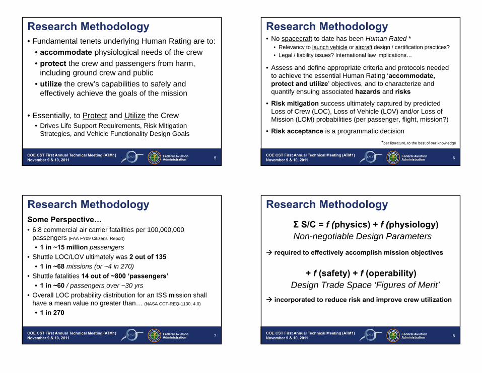
Research Methodology• Fundamental tenets underlying Human Rating are to:
• accommodate physiological needs of the crew
• protect the crew and passengers from harm, including ground crew and public
• utilize the crew’s capabilities to safely and effectively achieve the goals of the mission
• Essentially, to Protect and Utilize the Crew• Drives Life Support Requirements, Risk Mitigation
Strategies, and Vehicle Functionality Design Goals
Federal AviationAdministration 6
COE CST First Annual Technical Meeting (ATM1)November 9 & 10, 2011
Research Methodology• No spacecraft to date has been Human Rated *
• Relevancy to launch vehicle or aircraft design / certification practices?
• Legal / liability issues? International law implications…
• Assess and define appropriate criteria and protocols needed to achieve the essential Human Rating ‘accommodate, protect and utilize’ objectives, and to characterize and quantify ensuing associated hazards and risks
• Risk mitigation success ultimately captured by predicted Loss of Crew (LOC), Loss of Vehicle (LOV) and/or Loss of Mission (LOM) probabilities (per passenger, flight, mission?)
• Risk acceptance is a programmatic decision
*per literature, to the best of our knowledge
Federal AviationAdministration 7
COE CST First Annual Technical Meeting (ATM1)November 9 & 10, 2011
Research MethodologySome Perspective… • 6.8 commercial air carrier fatalities per 100,000,000
passengers (FAA FY09 Citizens’ Report)
• 1 in ~15 million passengers• Shuttle LOC/LOV ultimately was 2 out of 135
• 1 in ~68 missions (or ~4 in 270)• Shuttle fatalities 14 out of ~800 ‘passengers’
• 1 in ~60 / passengers over ~30 yrs• Overall LOC probability distribution for an ISS mission shall
have a mean value no greater than… (NASA CCT-REQ-1130, 4.0)
• 1 in 270
Federal AviationAdministration 8
COE CST First Annual Technical Meeting (ATM1)November 9 & 10, 2011
Research Methodology
Σ S/C = f (physics) + f (physiology)Non-negotiable Design Parameters
required to effectively accomplish mission objectives
+ f (safety) + f (operability)Design Trade Space ‘Figures of Merit’
incorporated to reduce risk and improve crew utilization

3
Federal AviationAdministration 9
COE CST First Annual Technical Meeting (ATM1)November 9 & 10, 2011
NASA CCT-REQ-1130 ISS Crew Transportation and Services Requirements Document
NASA SSP-50808 ISS to COTS Interface Requirements Document
NASA NPR 8705.2B Human-Rating Requirements for Space Systems
AFSPCMAN-91-710 Range Safety User Requirements
131
31ESMD-CCTSCR-12.10 CCTS Certification Requirements for NASA LEO Missions
258
Requirements
724
4692
5721
Research MethodologyGoverning Documents
Federal AviationAdministration 10
COE CST First Annual Technical Meeting (ATM1)November 9 & 10, 2011
Research MethodologySelect Literature (of ~160+)
• NASA (1965), “Apollo Launch-Vehicle Man-Rating: Some Considerations and an Alternative Contingency Plan”, RM-4489-NASA, May 1965.
• Hacker, BC and Grimwood, JM (1977), “On the Shoulders of Titans: A History of Project Gemini”, NASA SP-4203.
• NASA (1988), “Guidelines for Man Rating Space Systems,” JSC-23211, September 1998.
• NASA (1995), “A Perspective on the Human-Rating Process of U.S. Spacecraft: Both Past and Present”, NASA-SP-6104, 1995.
• Bond, AC (1998), “A Review of the Man-Rating in Past and Current Manned Space Flight Programs”
• Aerospace America (2010), “Human Rating: A Roundtable Discussion”, American Institute of Aeronautics and Astronautics, Vol. 48, No. 7
• Franzini, BJ and Fragola, JR (2011), "Human rating of launch vehicles: Historical and potential future risk," Reliability and Maintainability Symposium, Lake Buena Vista, FL, Jan 24-27, 2011.
Federal AviationAdministration 11
COE CST First Annual Technical Meeting (ATM1)November 9 & 10, 2011
Results or Schedule/Milestones ~yr 1
• Task 1 – Literature review, ~160 papers compiled and categorized to date, government / industry practice surveys in work
• Task 2 – Attended COE Roadmap Workshop Wash. DC (August 2011) and assimilated outcome into research objectives
• Task 3 – Collaboration with stakeholders initiated, other commercial partners are being contacted
• Goals identified during the Washington DC Roadmap Workshop to be further reviewed with industry and government partners
• Task 4 – COE research objectives for Human Rating task being aligned with academic plans for the PhD student, Christine, working on this project
Federal AviationAdministration 12
COE CST First Annual Technical Meeting (ATM1)November 9 & 10, 2011
Next Steps – outcome from Aug 2011 Roadmap Workshop

4
Federal AviationAdministration 13
COE CST First Annual Technical Meeting (ATM1)November 9 & 10, 2011
Next Steps – outcome from Aug 2011 Roadmap Workshop
Federal AviationAdministration 14
COE CST First Annual Technical Meeting (ATM1)November 9 & 10, 2011
Next Steps – outcome from Aug 2011 Roadmap Workshop
Federal AviationAdministration 15
COE CST First Annual Technical Meeting (ATM1)November 9 & 10, 2011
Next Steps – new AIAA ICES Conference Session, July 2012
Human Rating for Space SystemsThis session engages industry, government, and academia in the definition and analysis of safety and mission assurance parameters as they relate to the design and operations of spacecraft intended for human occupancy. One key objective is to assess the relevancy and commonality of requirements and policies for NASA and FAA commercial human spaceflight missions.
Organizers:David Klaus, University of Colorado, klaus@ colorado.eduRene Rey, FAA
Federal AviationAdministration 16
COE CST First Annual Technical Meeting (ATM1)November 9 & 10, 2011
Contact Information
Professor David KlausAerospace Engineering Sciences Dept.University of Colorado / 429 UCBBoulder, CO 80309-0429

5/15/2012
1
1
Unified 4D Trajectory Approach for Integrated
Management of Commercial Air and Space
Traffic
FAA CoE for CST Technical MeetingMillennium Harvest House, Boulder, CO
November 9, 2011
Juan J. Alonso and Thomas ColvinDepartment of Aeronautics & Astronautics
Stanford University
1 2
Overview
• Team members
• Purpose of Task
• Research Methodology
• Results
• Next Steps
• Contact Information
3
Team Members
• PI: Juan J. Alonso, Department of Aeronautics & Astronautics, Stanford University
• Thomas J. Colvin, Graduate Student, Department of Aeronautics and Astronautics, Stanford University
• Collaborations/discussions with:
• Banavar Sridhar, NASA Ames
• Karl Billimoria, NASA Ames
4
Purpose of Task
• Projected growth in demand will make it increasingly hard to accommodate launches on a SUA basis
• Looking for a more rational approach that:
• can adapt to fluctuating frequency of launches
• can accommodate uncertainties in trajectories
• ensures proper separation at all times
• can be integrated with FAA’s NextGen system
5/15/2012
2
5
Research Objectives
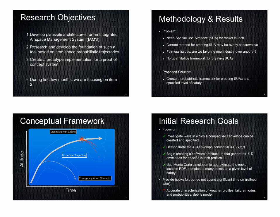
1.Develop plausible architectures for an Integrated Airspace Management System (IAMS)
2.Research and develop the foundation of such a tool based on time-space probabilistic trajectories
3.Create a prototype implementation for a proof-of-concept system
• During first few months, we are focusing on item 2
6
Methodology & Results• Problem:
Need Special Use Airspace (SUA) for rocket launch
Current method for creating SUA may be overly conservative
Fairness issues: are we favoring one industry over another?
No quantitative framework for creating SUAs
• Proposed Solution:
Create a probabilistic framework for creating SUAs to a specified level of safety
7
Conceptual Framework
Uncertain Trajectory
Time
Alti
tude
8
Initial Research Goals• Focus on:
✓ Investigate ways in which a compact 4-D envelope can be created and specified
✓Demonstrate the 4-D envelope concept in 3-D (x,y,t)
✓Begin creating a software architecture that generates 4-D envelopes for specific launch profiles
✓Use Monte Carlo simulation to approximate the rocket location PDF, sampled at many points, to a given level of safety
• Provide hooks for, but do not spend significant time on (refined later):
- Accurate characterization of weather profiles, failure modes and probabilities, debris model

5/15/2012
3
9
• 2-D round rotating Earth
Propagate r, V, φ, γ
• SSTO launch vehicle
• Optimal trajectory has thrust vectoring (T, ξ)
• Aerodynamic effects are roughly modeled
Nominal Trajectory
Source: Capristan, F. “Aerodynamic Effects in Launch Vehicle Optimal Trajectories”
10
Weather Uncertainty5% Uncertainty in Temperature
20% Uncertainty in Wind Velocity
11
Creates Drag Uncertainty
12
Uncertain Lift-off Time
• Rockets do not always launch on time
One-sided, multi-modal pdf

5/15/2012
4
13
Failure Uncertainty
Assume 1% of all launches fail
Failure occurs near pad or at max q
14
• Software framework that accepts arbitrary:
• Thrust profiles (TVC, etc)
• Weather profiles for wind and temperature, with uncertainty parameters for each
• Failure parameters and distributions
• Debris model
• Outputs:
• Collection of uncertain trajectories with debris-generating failure events from a MC simulation
What We’ve Got So Far
15
• Trajectories as points in space and time
• Risk level of 10^-10, approximated with MC
• How do we turn this set of trajectories into something useful?
• Methods Available
• Level Sets
• Delauney Triangulation
• Convex Hulls
• Non-convex Footprints
4D Probabilistic Trajectories and Envelopes
16
Swinging Arm• Generates multiple
disconnected “footprints”
• Non-convex, non-regular polygon
• Creates groupings that visually appear more accurate
• Generalizes up to 3D
• Arm short enough, multiple footprints
• Cons:
• Non-regular polygons
Source: Galton, A. “What is the region occupied by a set of points?”

5/15/2012
5
17
Footprint Example
18
QuickTime™ and a decompressor
are needed to see this picture.
Footprint Example
19
Making the next footprint• Arm length short
enough, get multiple footprints
• Remove interior and boundary points
• Crossings:
• Odd is in
• Even is out
20
An Early Footprint
QuickTime™ and a decompressor
are needed to see this picture.

5/15/2012
6
21
Footprint Through NAS (L=40km)
QuickTime™ and a decompressor
are needed to see this picture.
22
Footprint Through NAS (L=4km)
QuickTime™ and a decompressor
are needed to see this picture.
23
Footprint Through NAS (L=2km)
QuickTime™ and a decompressor
are needed to see this picture.
24
• Tube: 51,400 km2 sec
• Conservative. No safety factors.
• Convex: 15,300 km2 sec
• 30% of the original volume
• Footprint 2km arm: 6,500 km2 sec
• Only 13% of the original volume!
Volume Savings
QuickTime™ and a decompressor
are needed to see this picture.

5/15/2012
7
25
• Conclusions:
• Code accepts arbitrary thrust, weather, and failure profiles for Monte Carlo simulation of uncertain trajectories
• Creates multiple polygonal envelopes around the trajectories (and debris) that represent a no-fly zone
• Demonstrates the possibility of significant volume (area*sec) savings over conventional tube approach
• Future Work:
Full 4-D (Swinging Slab)
Accurate weather and debris models with uncertainty
Active control in rocket during ascent and staging
Integration with NASA’s FACET tool for scenarios with various launch sites frequencies + typical day in the NAS
Conclusions & Future Work
26
• De Berg, M., et al. “Computational Geometry - Algorithms and Applications”, Springer 1998
• Capristan, F. “Aerodynamic Effects in Launch Vehicle Optimal Trajectories”, Stanford 2010
• Osher, S.J., Fedkiw, R.P. “Level Set Methods and Dynamic Implicit Surfaces”, Springer 2002
• Galton, A., Duckham, M. “What is the region occupied by a set of points?” GIScience 2006, LNCS 4197, pp. 81-98, 2006
• Goldman, R. "Intersection of Two Lines in Three-Space." In Graphics Gems I (Ed. A. S. Glassner). San Diego: Academic Press, p. 304, 1990.
• Colonno, M. R., S. Reddy, and J. J. Alonso. "Multi-Fidelity Trajectory Optimization with Response Surface-Based Aerodynamic Prediction." (2008)
• Stengel, Robert. "Launch Vehicle Design: Trajectories and Aerodynamics." Launch Vehicle Design Class Notes. N.p., n.d. Web. 26 May 2010. <http://www.princeton.edu/~stengel/MAE342Lecture3.pdf>.
References
27
Backup Slides
28
Level Sets• Useful for visualizing dynamic
interfaces
• N-Dimensional surface is slice of an (N+1)D function
• Easily handles pinching and merging interfaces
• Set operations are easySource: http://en.wikipedia.org/wiki/Level_set_method

5/15/2012
8
29
• Hard to create the distance function
• Finding the area enclosed is not straightforward
• Allows holes within the boundary
• Slow
QuickTime™ and a decompressor
are needed to see this picture.
Level Set Example
30
Delauney Triangulation
Source: Galton, A. “What is the region occupied by a set of points?”
• Overview
• Connect all dots with series of triangles
• Remove boundary edges
• Generates single connected regular polygon
• Cons:
• Want to eliminate most points! Worth it?
• Creates a single shape
31
Convex Hulls
• Easy to generate
• Wastes a lot of space
• Only get one shape
• Can get these with footprint methods
32
• Order all points from top to bottom, right to left.
• Set all points as ‘available’ and pick an arm length
• Store top-right available point in footprint and set it as current point:
• Swing the arm clockwise from current point until it hits another point
• Store this point as being in the footprint and set it as the new current point
• Repeat until current point == starting point
• Set all points that form or are interior to the footprint as ‘unavailable’
• Repeat until all points are unavailable
• xxxx
Swinging Arm Algorithm

1
Federal AviationAdministration 1
COE CST First Annual Technical Meeting (ATM1)November 9 & 10, 2011
Federal AviationAdministration
COE CST First Annual Technical Meeting:
Space Environment MMOD Modeling and Prediction
Sigrid Close
November 9, 2011 Federal AviationAdministration 2
COE CST First Annual Technical Meeting (ATM1)November 9 & 10, 2011
Overview• Team Members• Purpose of Task• Research Methodology• Results• Next Steps• Contact Information
Federal AviationAdministration 3
COE CST First Annual Technical Meeting (ATM1)November 9 & 10, 2011
Team Members • Sigrid Close, Stanford University• Alan Li, Stanford University (graduate student)
Federal AviationAdministration 4
COE CST First Annual Technical Meeting (ATM1)November 9 & 10, 2011
Purpose of Task• Spacecraft are routinely impacted by space debris and
natural impactors- Mechanical damage: “well-known”, larger (> 120 microns), rare- Electrical damage: “unknown”, smaller/fast, more numerous
• Debris vs. meteoroids threat to LEO spacecraft- Mechanical threat: comparable- Electrical threat: dominated by meteoroids
• Goal: Characterize impactor population through data analysis and modeling

2
Federal AviationAdministration 5
COE CST First Annual Technical Meeting (ATM1)November 9 & 10, 2011
Impactors
• Dust and Meteoroids− Speeds
• 11 to 72.8 km/s (interplanetary)• > 72.8 km/s (interstellar)
− Densities• rocky or ice-like
− Sizes• < 62 microns in diameter (dust)• 62 microns to 0.3 m in diameter (meteoroid)
• Space Debris− Speeds: < 12 km/s− Higher densities− Varying sizes
Federal AviationAdministration 6
COE CST First Annual Technical Meeting (ATM1)November 9 & 10, 2011
Methodology: Meteoroids• Models: Formation of plasma (PIC), Interaction of
electromagnetic waves with plasma (FDTD), Atmosphere• Data: Ground-based plasma, in-situ impact• Research and Deliverables
- Flux- Mass, density- Velocity, orbit
Time (sec)
Alti
tude
(km
)
SNR
(dB
)
Federal AviationAdministration 7
COE CST First Annual Technical Meeting (ATM1)November 9 & 10, 2011
Methodology: Debris• Models: Propagation of debris in space and time (Force
Model), Atmospheric models (MSIS, Jacchia-Bowman)• Data: Ground-based/in-situ impact for detection, Light-
gas gun for debris source• Research and Deliverables
- Flux- Source- Prediction
Federal AviationAdministration 8
COE CST First Annual Technical Meeting (ATM1)November 9 & 10, 2011
Radar Data High-power ground-based meteor observations
Multi-frequency, multi-polarization, high-sensitivity, high range resolution
RadarsALTAIR
MIT HaystackEISCAT
Arecibo Observatory
8

3
Federal AviationAdministration 9
COE CST First Annual Technical Meeting (ATM1)November 9 & 10, 2011
Meteoroid Plasma Modeling
Plas
ma
Freq
uenc
y (M
Hz)
Plasma Radius (a) (m)
|R|2
ALTAIR VHF
Federal AviationAdministration 10
COE CST First Annual Technical Meeting (ATM1)November 9 & 10, 2011
Meteoroid Results
Federal AviationAdministration 11
COE CST First Annual Technical Meeting (ATM1)November 9 & 10, 2011
Debris Modeling
11
• NASA: ORDEM, LEGEND• ESA: MASTERS• Modeling from sources, propagation, conjunction• Newer sources (perhaps hybrids), newest atmospheric
models (Jacchia-Bowman)• NASA collision model (inadequate in many areas)
- No material dependence- No size and shape factor dependence- Velocity distribution inadequate
Federal AviationAdministration 12
COE CST First Annual Technical Meeting (ATM1)November 9 & 10, 2011
Debris Results• Based upon three primary sources
- US Space Command Catalog, Haystack Radar, and in-situ- Auxiliary data provided by HAX radar, Goldstone radar, returned
solar array from Hubble Space Telescope
• Extrapolation based upon EVOLVE for ranges of debris where data is scarce
-200
2040
6080
100
0
500
1000
1500
20000
0.2
0.4
0.6
0.8
1x 10⁻⁷
Latitude [degrees]
Spatial Density vs Latitude and Altitude for Debris > 10 cm
Altitude [km]
Spat
ial D
ensi
ty [n
o/km
2 ]
-200
2040
6080
100
0
500
1000
1500
20000
10
20
30
40
Latitude [degrees]
Spatial Density vs Latitude and Altitude for Debris > 0.001 cm
Altitude [km]
Spa
tial D
ensi
ty [n
o/km
2 ]
12

4
Federal AviationAdministration 13
COE CST First Annual Technical Meeting (ATM1)November 9 & 10, 2011
Next Steps• Meteoroids
- Compressed sensing techniques for improved detection/analysis- Force modeling for improved orbit determination- Electromagnetic scattering models for plasma diagnostics
• Debris- Characterization of all sources/breakups- Comparison between MASTERS/ORDEM- Propagation and atmospheric models
Federal AviationAdministration 14
COE CST First Annual Technical Meeting (ATM1)November 9 & 10, 2011
Publications• Close et al., “Determining Meteoroid Bulk Densities Using
a Plasma Scattering Model with High-Power Large-Aperture Radar Data”, Icarus, in review, 2011
• Reference: National Academies Report: “Limiting Future Collision Risk to Spacecraft: An Assessment of NASA’s Meteoroid and Orbital Debris Programs”
Federal AviationAdministration 15
COE CST First Annual Technical Meeting (ATM1)November 9 & 10, 2011
Thank You!• Sigrid Close ([email protected])• Alan Li ([email protected])
Federal AviationAdministration 16
COE CST First Annual Technical Meeting (ATM1)November 9 & 10, 2011
Backup

5
Federal AviationAdministration 17
COE CST First Annual Technical Meeting (ATM1)November 9 & 10, 2011
ALTAIR Radar Data
VHF
UHF
Time (sec)85
105
Alti
tude
(km
)
0 5
Federal AviationAdministration 18
COE CST First Annual Technical Meeting (ATM1)November 9 & 10, 2011
Mechanical and Electrical Damage
Mechanical Damage
massdensity
plasma strengthvelocity
deceleration
Specs Radiated
power
18
Specs
Larger Impactors
FasterImpactors
ElectricalDamage

1
Federal AviationAdministration 1
COE CST First Annual Technical Meeting (ATM1)November 9 & 10, 2011
Federal AviationAdministration
COE CST First Annual Technical Meeting:
Mitigating threats through space environment modeling/prediction
PI: Tim Fuller-Rowell
Presented by
Tomoko Matsuo
November 9th, 2011 Federal AviationAdministration 2
COE CST First Annual Technical Meeting (ATM1)November 9 & 10, 2011
Team Members
Timothy Fuller-Rowell, Tomoko Matsuo, Houjun Wang, Fei WuCooperative Institute for Research in Environmental Sciences (CIRES)University of Colorado, BoulderNOAA Space Weather Prediction Center
Rashid Akmaev, Mihail Codrescu, Rodney ViereckNOAA Space Weather Prediction Center, Boulder, CO
Jeffrey ForbesAerospace Engineer Sciences, University of Colorado, Boulder
Federal AviationAdministration 3
COE CST First Annual Technical Meeting (ATM1)November 9 & 10, 2011
Purpose of Task
Purpose: An integrated air and space traffic management system requires seamless and real-time access to density predictions for on-orbit collision avoidance and atmospheric re-entry, and near-surface weather prediction
Objectives: Develop a “weather” (terrestrial weather and space weather) prediction model extending from Earth’s surface to the edge of space
Goals: Predict the environmental conditions needed for safe orbital, sub-orbital, re-entry, descent, and landing
Federal AviationAdministration 4
COE CST First Annual Technical Meeting (ATM1)November 9 & 10, 2011
Drivers of the density variability
Actual Position
Predicted Position
Understandable:since 80% of the forcing above 200km comes from solar and geomagnetic activity
Satellite drag and orbit prediction has traditionally relied on understanding the response to solar and geomagnetic forcing

2
Federal AviationAdministration 5
COE CST First Annual Technical Meeting (ATM1)November 9 & 10, 2011
So why a Whole Atmosphere Model• Re-entry calculations have been notoriously bad at predicting
place and time of impact
• With rise in Commercial Space Transportation increasing use of sub-orbital vehicles and need for controlled re-entry, decent and landing
• Altitude region of interest is impacted by both “terrestrial or tropospheric weather” and “space weather”
• Therefore need to characterize the atmospheric conditions seamlessly from the ground to orbital altitudes
Federal AviationAdministration 6
COE CST First Annual Technical Meeting (ATM1)November 9 & 10, 2011
Whole Atmosphere Model (WAM)• T62L150 (~ 22, ~ 0-600 km) • Composition thermodynamics• Timing ~ 8 min/day on 32 nodes
Physics- Horizontal & vertical mixing- Radiative heating (EUV & UV) and
cooling (non-LTE)- Ion drag & Joule heating- Major species composition- Non-orographic gravity waves- Eddy mixing
Whole Atmosphere Model (WAM)Global Forecast System (GFS)
• T382L64 (~ 0.30.3, ~ 0-60 km)• 4 forecasts daily• Global ensemble (14 members)
forecasts up to 16 days
Physics- O3 chemistry (parameterized) &
transport- Radiative heating and cooling- Cloud physics & hydrology- Surface exchange processes- Orographic gravity waves- Eddy mixing and convection
Federal AviationAdministration 7
COE CST First Annual Technical Meeting (ATM1)November 9 & 10, 2011
Strong Variability at Sub-orbital / Re-entry Altitudes
Observed Variability:zonal winds at mid/low latitudes from rocket-released chemical trails (Larsen, 2002)
Federal AviationAdministration 8
COE CST First Annual Technical Meeting (ATM1)November 9 & 10, 2011
Data Assimilation
• Gridpoint Statistical Interpolation (GSI) is the NCEP operational analysis system for global and regional NWP
• Uses a 3-D variational (3DVAR) analysis technique
• Replace GFS with WAM
• Analysis system was modified to use incremental analysis updates (IAU) to avoid use of digital filter, which excessively damps tidal propagation to the thermosphere
• Simulate January 2009 and 2010 periods during large sudden stratospheric warmings

3
Federal AviationAdministration 9
COE CST First Annual Technical Meeting (ATM1)November 9 & 10, 2011
70KComparison withEuropean Centre for Medium Range Weather Forecasting (ECMWF)
Terrestrial Weather:Jan 2009 SSW
Federal AviationAdministration 10
COE CST First Annual Technical Meeting (ATM1)November 9 & 10, 2011
• Global thermosphere 80 - 500 km, solves momentum, energy, composition, etc., O, O2, N2 (Fuller-Rowell et al., 1996)
• Global ionosphere 80 - 10,000 km, solves plasma continuity, momentum, energy, electrodynamics etc., O+, H+, O2
+, NO+, N2
+, N+(Millward et al., 1996)
• Solar and geomagnetic forcing solar UV and EUV, Weimer electric field, TIROS/NOAA auroral precipitation
(Fedrezzi et al., 2011)
Space Weather Modeling: Coupled Thermosphere-Ionosphere-Plasmasphere (CTIPe) Model
Coupling with WAM
Federal AviationAdministration 11
COE CST First Annual Technical Meeting (ATM1)November 9 & 10, 2011
Summary• WAM is designed to forecast the environmental conditions from the
ground to 600km• WAM will cover the orbital, sub-orbital, re-entry, descent, and landing
requirements for atmospheric density• WAM will simulate the internal atmospheric sources of variability (gravity waves,
tides, planetary waves, midnight density maximum, wave 4 structure, sudden stratospheric warmings, etc.)
• Coupled to an ionosphere module, WAM will also be able to respond to space weather forcing (solar flares, geomagnetic storms, solar proton events) to address not only density requirements, but also communications and navigation needs
• WAM will follow, and forecast several days ahead, the whole atmosphere dynamical response to atmospheric processes using a modified version of the NCEP GSI operational data assimilation system
• WAM will also provide environment conditions for micrometeoroid and orbital debris detection / avoidance (Sigrid Close) and collision probability for space situational awareness (Dan Scheeres)
Federal AviationAdministration 12
COE CST First Annual Technical Meeting (ATM1)November 9 & 10, 2011
Next Steps• Extend WAM data assimilation into the lower thermosphere
(SABER, MLS temperatures, etc.)
• Test higher resolution WAM T382 (35 km resolution) to resolve wave field penetrating to the thermosphere and test semi-annual variation in density
• Full coupling of the ionosphere (e.g., Ionosphere-Plasmasphere-Electrodynamcis (IPE) model, CTIPe) to respond to solar and magnetospheric forcing
• Explore assimilation of ionospheric data for density prediction
• Whole atmosphere/ionosphere data assimilation at high resolution
• Transition at NOAA

4
Federal AviationAdministration 13
COE CST First Annual Technical Meeting (ATM1)November 9 & 10, 2011
Contact Information• Dr. Tim Fuller-Rowell, Physicist, Cooperative Institute for Research in Environmental Sciences,
University of Colorado/Space Weather Prediction Center, [email protected]
• Dr. Tomoko Matsuo, Physicist, Cooperative Institute for Research in Environmental Sciences, University of Colorado/Space Weather Prediction Center, [email protected]
• Dr. Houjun Wang, Physicist, Cooperative Institute for Research in Environmental Sciences, University of Colorado/Space Weather Prediction Center, [email protected]
• Dr. Fei Wu, Physicist, Cooperative Institute for Research in Environmental Sciences, University of Colorado/Space Weather Prediction Center, [email protected]
• Dr. Rashid Akmaev, Physicist, NOAA/Space Weather Prediction Center, [email protected]
• Dr. Mihail Codrescu, Physicist, NOAA/Space Weather Prediction Center, [email protected]
• Dr. Rodney Viereck, Physicist, NOAA/Space Weather Prediction Center, [email protected]
• Professor Jeffrey M. Forbes, Department Chair, Aerospace Engineering Sciences, University of Colorado, [email protected]

Federal AviationAdministration
COE CST First Annual Technical Meeting (ATM1)November 9 & 10, 2011 1
Federal AviationAdministration
COE CST First Annual Technical Meeting:
Space Situational Awareness
D.J. Scheeres
November 9, 2011 Federal AviationAdministration
COE CST First Annual Technical Meeting (ATM1)November 9 & 10, 2011 2
Overview•Team Members•Purpose of Task•Research Methodology•Results•Next Steps•Contact Information
Federal AviationAdministration
COE CST First Annual Technical Meeting (ATM1)November 9 & 10, 2011 3
SSA Team Members Direct Support from the FAA COE•Dan Scheeres, CU Professor, PI•George Born, CU Professor, Co-I•Bob Culp, CU Professor Emeritus, Co-I•Brandon Jones, CU Research Scientist•Kohei Fujimoto, CU PhD CandidateRelated Research from Fellowship Students•Aaron Rosengren, CU Graduate Student•Antonella Albuja, CU Graduate Student•Ddard Ko, CU Graduate StudentGovernment and Industry Partners•AFRL Kirtland and Maui•NASA Orbit Debris Program Office •Analytical Graphics, Incorporated•Orbital Sciences Corporation

Federal AviationAdministration
COE CST First Annual Technical Meeting (ATM1)November 9 & 10, 2011 4
Purpose of Task•Space Situational Awareness
SSA = Cognizance of Resident Space Objects (RSO) and activities in orbital regions of interest, both now and in the short and long-range future.
•Objectives: Improve SSA abilities in regions of interest to the FAA for space-based activities.
•Current regions of focus: LEO-down and GEO-up•Goals are to improve: uncertainty modeling and propagation, precision long-term orbit propagation, non-gravitational model prediction and estimation, orbit estimation techniques.
D.J. Scheeres, A. Richard Seebass Chair, University of Colorado at Boulder 5
Long-Term Probability Density Function Propagation
• Developing novel semi-analytical solutions for propagation– Enables rapid and accurate uncertainty propagation
– Leverages decades of research in analytical celestial mechanics research
– Is being extended to perturbations and non-conservative forces
– Serves as an enabling and foundational framework for other advances in estimation, dynamic modeling, and conjunction analysis
2-Body Propagation over 100 orbits
80 60 40 20 0 20 40 60−12
−10
−8
−6
−4
−2
0
2x 10
−3
2-Body + Drag over 10 orbits
D.J. Scheeres, A. Richard Seebass Chair, University of Colorado at Boulder 6
Non-Gravitational Modeling & Dynamics
• Solar Radiation Pressure non-grav models developed for asteroids can be directly applied to RSO dynamics and models– Time scale of interest for asteroids, ~ 1E4 -> 1E6 years
– Equivalent time scale of interest for RSO ~2 -> 200 years for LEO to GEO
– Current focus on High Area to Mass Ratio object dynamics in GEO, rotational dynamics of debris, estimation of non-grav models (drag and solar radiation)
Initial Condition
A/M = 15
A/M = 45
A/M = 75
esinω
e cosω
−1 −0.5 0 0.5
−0.8
−0.6
−0.4
−0.2
0
0.2
0.4
0.6
0.8
1
Eccentricity Vector of HAMR Objects
0 2 4 6 8 100
0.5
1
1.5
2
2.5
3
3.5x 10
8 Eccentricity
# of Orbits
Ecc
entr
icity
NumericalAnalyticalShort
Eccentricity of the Grace Satellite
of Colorado at Boulder
0
D.J. Scheeres, A. Richard Seebass Chair, University of Colorado at Boulder
Short-Arc RSO Correlation
• Given two observations of RSO separated in time, can we determine if these are the same object?
• If they are, can we achieve an initial orbit determination estimate?
• A new approach to initial orbit determination and correlation has been developed – “Best Paper of Conference” in 2010.– Hypothesis-free correlation testing – fundamental improvement of process
– Robust and rigorous approach to combining sparse track observations
– Method based on the topology of probability density functions in 6-D space
7

Federal AviationAdministration
COE CST First Annual Technical Meeting (ATM1)November 9 & 10, 2011 8
Lp-norm Orbit Determination• Orbit determination in LEO faces data association and quality challenges.
• Mis-tagged data or measurement outliers can force an orbit estimate to diverge or yield poor convergence that compromises the entire catalog maintenance activity.
• To remedy this we are developing nonlinear, adaptive estimation capabilities that are independent of and insensitive to measurement error distribution
• Current focus is on using minimum L1-norm orbit determination, which provides robust estimation capabilities that are insensitive to data mis-tagging and outliers.
• Tools are being developed to explore the applicability and use of this approach
Federal AviationAdministration
COE CST First Annual Technical Meeting (ATM1)November 9 & 10, 2011 9
Results since commencement of funding
• Journal Papers in press:• K. Fujimoto and D.J. Scheeres. “Correlation of Optical Observations of Earth-Orbiting Objects and Initial Orbit Determination,"
Journal of Guidance, Control and Dynamics, in press, 2011.
• K. Fujimoto, D.J. Scheeres and K.T. Alfriend. “Analytical Non-Linear Propagation of Uncertainty in the Two-Body Problem," Journal of Guidance, Control and Dynamics , in press, 2011.
• Conference Papers:• K. Fujimoto, D.J. Scheeres , and K.T. Alfriend. “Analytical Non-Linear Propagation of Uncertainty in the Two-Body Problem," paper
presented at the 2011 AAS/AIAA Spaceflight Mechanics Meeting, New Orleans, February 2011. Paper AAS 11-202.
• A. Rosengren and D.J. Scheeres. “Averaged Dynamics of HAMR Objects: Effects of Attitude and Earth Oblateness,” paper presented at the 2011 AAS/AIAA Astrodynamics Specialist Meeting, Girdwood, Alaska, August 2011. Paper AAS 11-594.
• D.J. Scheeres and A. Rosengren. “Closed Form Solutions for the Averaged Dynamics of HAMR Objects,” paper presented at the 62nd International Astronautical Congress, Cape Town, South Africa, October 2011.
• K. Fujimoto and D.J. Scheeres. “Non-Linear Propagation of Uncertainty With Non-Conservative Effects," paper submitted to the 2012 AAS/AIAA Spaceflight Mechanics Meeting, Charleston, SC, Jan/Feb 2012.
• S. Gehly, B. A. Jones, P. Axelrad, G. H. Born, "Minimum L1 Norm Orbit Determination Using a Sequential Processing Algorithm", paper submitted to the 2012 AAS/AIAA Spaceflight Mechanics Meeting, Charleston, SC, Jan/Feb 2012.
• Industry Interactions:• Exchanges of simulated data with AFRL Maui research personnel.
• Interactions with NASA Orbit Debris Program Office and the Center for Space Standards & Innovation (AGI)
• Dissemination of orbit determination tools to Aerospace Corp. researchers for analysis and testing.
Federal AviationAdministration
COE CST First Annual Technical Meeting (ATM1)November 9 & 10, 2011
Next Steps•Funding for Year 2 is now in-place.•Mechanisms for matching funds have been identified and taken advantage of.
•Research progressing on all fronts identified.•Dissemination of research into conference and journal literature is on-track.
Interested in collaborations with other COE-CST supported Research Tasks
10 Federal AviationAdministration
COE CST First Annual Technical Meeting (ATM1)November 9 & 10, 2011 11
Contact Information
720-544-1260

1
Federal AviationAdministration 1
COE CST First Annual Technical Meeting (ATM1)November 9 & 10, 2011
Federal AviationAdministration
COE CST First Annual Technical Meeting:
Defining the Future by Engaging Emerging
Leaders
Task 193:Role of COE CST in EFP
PI: George H. BornBradley Cheetham
11.10.2011 Federal AviationAdministration 2
COE CST First Annual Technical Meeting (ATM1)November 9 & 10, 2011
Overview• Team Members
• Task Purpose/Objectives
• Theory Based Analysis
• ESIL Workshops
• SpaceVision 2011
• Next Steps
• Contact Information
Federal AviationAdministration 3
COE CST First Annual Technical Meeting (ATM1)November 9 & 10, 2011
Team Members • George H. Born – Director, Colorado Center for
Astrodynamics Research
• Bradley Cheetham – Graduate Research Assistant, Aerospace Engineering Sciences
• Juliana Feldhacker – Graduate Research Assistant, Aerospace Engineering Sciences
Federal AviationAdministration 4
COE CST First Annual Technical Meeting (ATM1)November 9 & 10, 2011
Purpose of Task• Objectives:
• Identify key industry characteristics to facilitate EFP efforts
• Support on-going FAA COE CST roadmapping efforts
• Hosted workshops for student and young professionals
• Support conferences to educate students and young professionals
• Incorporate young professional perspectives in ongoing efforts

2
Federal AviationAdministration 5
COE CST First Annual Technical Meeting (ATM1)November 9 & 10, 2011
FAA COE CST Objectives• Research
• Industry Structural Analysis – Commercial Crew to Orbit Industry Segment
• Training• Emerging Space Industry Leaders (ESIL-01)
Workshop
• Outreach• SpaceVision2011 Support
Federal AviationAdministration 6
COE CST First Annual Technical Meeting (ATM1)November 9 & 10, 2011
Theory Based AnalysisStrategic Evaluation of Commercial Crew to Orbit Transportation Industry Structure and Status
• Presented at 2011 International AstronauticalCongress
• IAC-11-D4.2.1
• Second iteration on analysis
• Based on Michael Porter Competitive Strategy Theory
Federal AviationAdministration 7
COE CST First Annual Technical Meeting (ATM1)November 9 & 10, 2011
Theory Based AnalysisScope: Commercial delivery of humans to Earth orbit
– Considering the transport vehicle only
– Launch vehicle is a supplier
Federal AviationAdministration 8
COE CST First Annual Technical Meeting (ATM1)November 9 & 10, 2011
ESIL Workshop• Bring together emerging industry leaders
• Objectives• Inform – perspective, background, context
• Perform – group analysis on identified market
• Network – internal and external to industry
• Output• Theory based analysis on self-selected market

3
Federal AviationAdministration 9
COE CST First Annual Technical Meeting (ATM1)November 9 & 10, 2011
ESIL WorkshopESIL-01
10.26-10.27
Federal AviationAdministration 10
COE CST First Annual Technical Meeting (ATM1)November 9 & 10, 2011
ESIL Workshop
Federal AviationAdministration 11
COE CST First Annual Technical Meeting (ATM1)November 9 & 10, 2011
ESIL Workshop
Federal AviationAdministration 12
COE CST First Annual Technical Meeting (ATM1)November 9 & 10, 2011
SpaceVision 2011• Objective
• Support dissemination of industry information to broad diverse student population
• Mechanism of Support• Partner with CU SEDS chapter
• Speaker advising and assistance
• Recording/Dissemination of programming
• Corporate partnerships

4
Federal AviationAdministration 13
COE CST First Annual Technical Meeting (ATM1)November 9 & 10, 2011
SpaceVision 2011
Federal AviationAdministration 14
COE CST First Annual Technical Meeting (ATM1)November 9 & 10, 2011
SpaceVision 2011
Federal AviationAdministration 15
COE CST First Annual Technical Meeting (ATM1)November 9 & 10, 2011
SpaceVision 2011
Federal AviationAdministration 16
COE CST First Annual Technical Meeting (ATM1)November 9 & 10, 2011
Next Steps• Industry Structural Analysis
• Third iteration as industry evolves – Fall 2012
• ESIL-02• Discussing options in Spring 2011
• ESIL-##• Future workshops hosted around the country in
collaboration with other industries
• SpaceVision 2012• Support efforts Fall 2012

5
Federal AviationAdministration 17
COE CST First Annual Technical Meeting (ATM1)November 9 & 10, 2011
Contact Information
George H. [email protected]
Bradley [email protected]
Federal AviationAdministration 18
COE CST First Annual Technical Meeting (ATM1)November 9 & 10, 2011
Questions

Federal Aviation Administration 1
COE CST First Annual Technical Meeting (ATM1) November 9 & 10, 2011
Federal Aviation Administration COE-CST Research
Roadmapping
Professor Scott Hubbard & Graduate Student Jonah Zimmerman
Department of Aeronautics and Astronautics
Stanford University
November 10th, 2011 Federal Aviation Administration 2
COE CST First Annual Technical Meeting (ATM1) November 9 & 10, 2011
• Phase I - Preliminary Foundation - Identify Scope - Find leadership and acquire sponsorship - Demonstrate problem being solved
• Phase II - Development Phase - Designate “product” that is the focus - Identify the critical requirements and technology/research areas - Study research alternatives and create needs timeline - Write roadmap report
• Phase III - Building Consensus and Follow-up - Explain roadmap to larger community - Obtain independent critique and validation - Update as needed
Roadmapping Methodology
*Adapted from Fundamentals of Technology Roadmapping , Garcia and Bray, SNL, 1997
Current Status: Beginning Phase III
Federal Aviation Administration 3
COE CST First Annual Technical Meeting (ATM1) November 9 & 10, 2011
Workshops • Stanford University -April 6-7, 2011 -51 representatives of industry, academia,
government -Defined initial theme objectives and structure
• Washington DC -Lockheed Martin Global Vision Center -August 15-17, 2011 -73 representatives in attendance -Refined theme structure and research prioritization
Federal Aviation Administration 4
COE CST First Annual Technical Meeting (ATM1) November 9 & 10, 2011
Results
Finalized Research Theme Structures

Federal Aviation Administration 5
COE CST First Annual Technical Meeting (ATM1) November 9 & 10, 2011
Results – Research Priorities • Theme 1 - Space Traffic Management (STM) and Operations: - Mission Statement: The STM task will focus on facilitating commercial
utilization of orbital space resources, free from physical interference, by implementing technical and regulatory provisions. The National Airspace System (NAS) integration and spaceport operations task will focus on integrating commercial space vehicle and spaceport operations into the NAS by providing equitable sharing of NAS resources for both air and space traffic.
- High-Priority Research: In order to reduce the imposition made on the National Airspace System and facilitate the integration of air and space vehicle traffic, a minimum safe corridor for launches and re-entries must be identified.
Federal Aviation Administration 6
COE CST First Annual Technical Meeting (ATM1) November 9 & 10, 2011
Results – Research Priorities • Theme 2 - Space Transportation Operations,
Technologies, and Payloads: -Mission Statement: Perform research to significantly
improve reliability/safety/risk posture and availability for stakeholders in full mission cycle vehicle operations and ground operations while ensuring that proper business case closes (and no negative interactions with rest of participants).
-Recommendation: Further effort is ongoing to identify top research objectives from the technological landscape. This will require iterative effort between this theme and the other three themes.
Federal Aviation Administration 7
COE CST First Annual Technical Meeting (ATM1) November 9 & 10, 2011
Results – Research Priorities • Theme 3 - Human Spaceflight: -Mission Statement: It is the goal of the human spaceflight
research area to optimize the human and spacecraft systems for performance, safety, and access for commercial human spaceflight.
-High-Priority Research: Verifiable guidelines are needed for all spaceflight participants. To develop these, extensive data on the risks of various medications and conditions in the space environment are required.
Federal Aviation Administration 8
COE CST First Annual Technical Meeting (ATM1) November 9 & 10, 2011
Results – Research Priorities • Theme 4 - Space Transportation Industry Viability: -Mission Statements: - 1) The purpose of the Industry Viability research area
support effective policy decision-making and reflect the dual regulatory and promotional missions of the FAA Office of Commercial Space Transportation.
- 2) Research addressing regulation is designed to maximize regulatory cost-effectiveness; research concerning promotion aims to maximize industry growth.
-High-Priority Research: What “the market” is remains an open question to the CST industries. Identifying and verifying the suborbital and orbital microgravity commerce and research opportunities is of prime importance.

Federal Aviation Administration 9
COE CST First Annual Technical Meeting (ATM1) November 9 & 10, 2011
Results – Sample Research Tasks • Theme 1 - Space Traffic Management (STM) and Operations:
- De-confliction of air and space traffic • Required airspace for different vehicles and missions • Air-space transition corridors
• Theme 2 - Space Transportation Operations, Technologies, and Payloads: - Research and recommend safe, expeditious, and cost efficient processing of
reusable manned or unmanned vehicles that are payloads on ELV’s • Landing, inspection, modification if needed, transportation, and integration
• Theme 3 - Human Spaceflight: - Evaluate specific medical conditions in high-g environment utilizing centrifuge
facilities - Support the development of medical kits for various suborbital and orbital flight
scenarios • Theme 4 - Space Transportation Industry Viability:
- Retrospective analysis of: • Transition from government to private customers • Commercial failures
- Proactive analysis of research capabilities and research requirements
Federal Aviation Administration 10
COE CST First Annual Technical Meeting (ATM1) November 9 & 10, 2011
Future Work • Report status: -First draft completed -Major revisions based on Ken Davidian’s
comments underway • Next steps: -Disseminate results to the community -Improve based on resulting comments and
critiques -Update periodically -Implement roadmap into COE’s research planning
and decision making
Federal Aviation Administration 11
COE CST First Annual Technical Meeting (ATM1) November 9 & 10, 2011
Contact Information
• Scott Hubbard <[email protected]>
• jonah zimmerman <[email protected]>

5/15/2012
1
Federal AviationAdministration 1
COE CST First Annual Technical Meeting (ATM1)November 9 & 10, 2011
Federal AviationAdministration 1
COE CST First Annual Technical Meeting (ATM1)November 9 & 10, 2011
COE CST FIRST ANNUALTECHNICAL MEETING:
Develop an Accepted Framework to Capture the Body of Knowledge for Commercial Spaceport
Operations Best Practices Through 2012
PI: Patricia C. Hynes, Ph.D.
November 9, 2011
1
Federal AviationAdministration
Federal AviationAdministration 2
COE CST First Annual Technical Meeting (ATM1)November 9 & 10, 2011
Federal AviationAdministration 2
COE CST First Annual Technical Meeting (ATM1)November 9 & 10, 2011
Overview
• Team Members• Purpose of Task• US Spaceports• Research Methodology• Results• Next Steps• Website• Contact Information
2
Federal AviationAdministration 3
COE CST First Annual Technical Meeting (ATM1)November 9 & 10, 2011
Federal AviationAdministration 3
COE CST First Annual Technical Meeting (ATM1)November 9 & 10, 2011
Team Members• Pat Hynes, PI, New Mexico State University
• Herb Bachner, Commercial Space Working Group, CSSI
• Jim Hayhoe, Spaceport America Consultants
• Judy McShannon, New Mexico State University
• Paul Arthur, Rear Admiral (Retired), Former Technical Director/Deputy Commander, White Sands Missile Range
• Craig Day, Director, Business Development, AIAA
• Terri Alexander, Project Manager, The Boeing Company
• Robert Reuter, Project Manager, The Boeing Company
• Sandy Saunders, Vice President Operations, Locked On, Inc.• Morgan McPheeters, NMSU Graduate, Spring 2011
3Federal AviationAdministration 4
COE CST First Annual Technical Meeting (ATM1)November 9 & 10, 2011
Federal AviationAdministration 4
COE CST First Annual Technical Meeting (ATM1)November 9 & 10, 2011
Purpose of Task
Task 1: Develop a Framework ‐ CompletedPrepare the framework in collaboration with spaceport directors• February 2011 • Public meeting to discuss framework variables• Update framework variables to account for public input• Survey spaceport executive directors and selected range
operators
4

5/15/2012
2
Federal AviationAdministration 5
COE CST First Annual Technical Meeting (ATM1)November 9 & 10, 2011
Federal AviationAdministration 5
COE CST First Annual Technical Meeting (ATM1)November 9 & 10, 2011
U.S. SpaceportsCommercial/Government/Private Active and Proposed Launch Sites
Kodiak Launch Complex
Blue Origin Launch site
Vandenberg AFB
California Spaceport
Mojave AirportEdwards AFB
White Sands Missile Range
SpaceportAmerica
Oklahoma SpaceportWallops FlightFacility
Spaceport Florida
‐Kennedy Space Center‐Cape CanaveralAir Force Station
Mid‐AtlanticRegional Spaceport
Reagan Test SiteKwajalein Atoll, Marshall Islands
Sea Launch PlatformEquatorial Pacific Ocean
KeyU.S. Federal Launch Site (2)Non-Federal FAA-LicensedLaunch Site (7)Owned by University of Alaska GeophysicalInstituteSole Site Operator
Cecil FieldSpaceport
FAA/AST: August 2011
Other spaceports have been proposed by: Alabama, Washington,Hawaii, Wisconsin, Wyoming, Indiana and multiple locations in Texas.
Poker FlatResearchRange
Federal AviationAdministration 6
COE CST First Annual Technical Meeting (ATM1)November 9 & 10, 2011
Federal AviationAdministration 6
COE CST First Annual Technical Meeting (ATM1)November 9 & 10, 2011
Research Methodology
• Develop a framework for spaceport operations and test the framework through the use of a survey of Spaceport Directors and military Range Commanders.
• Analyze the classification system for further categories until the results of general operations procedures and practices reflect a comprehensive body of knowledge of best practices for commercial spaceport operations.
6
Federal AviationAdministration 7
COE CST First Annual Technical Meeting (ATM1)November 9 & 10, 2011
Federal AviationAdministration 7
COE CST First Annual Technical Meeting (ATM1)November 9 & 10, 2011
Results
• Survey• N=8 (spaceport directors and members of the Range Commanders Council who operate federal ranges)
• 142 variables were surveyed
7Federal AviationAdministration 8
COE CST First Annual Technical Meeting (ATM1)November 9 & 10, 2011
Federal AviationAdministration 8
COE CST First Annual Technical Meeting (ATM1)November 9 & 10, 2011
Include
Not In This Topic
Do Not Include
142 Survey Items (100%)
Broad Agreement Among Spaceport Operators
5%
86%
9%
Average Response Scores for COE Body of Knowledge

5/15/2012
3
Federal AviationAdministration 9
COE CST First Annual Technical Meeting (ATM1)November 9 & 10, 2011
Federal AviationAdministration 9
COE CST First Annual Technical Meeting (ATM1)November 9 & 10, 2011
Survey Results ‐sample
9
1.0 AIRFIELD AND LAUNCH OPERATIONS Include Do Not Include
Not in This Topic
1.1 OPERATIONAL INFRASTRUCTURE & ACTIVITIES1.1.1 Runways 87.5% 12.5% 0.0% 1.1.2 Terminal Facilities 75.0% 12.5% 12.5% 1.1.3 Aircraft Rescue & Fire Fighting Facilities 87.5% 0.0% 12.5% 1.1.4 Hazardous Materials Storage & Transfer Facilities 75.0% 0.0% 25.0% 1.1.5 Aircraft/Spacecraft Tie‐Down Areas 75.0% 25.0% 0.0% 1.1.6 Hangar Facilities 75.0% 25.0% 0.0% 1.1.7 Mission Control Facilities 75.0% 25.0% 0.0% 1.1.8 Launch Control Facilities 75.0% 25.0% 0.0% 1.1.8.1 Launch Pad Safety 50.0% 0.0% 50.0%1.1.8.2 Maintenance of Ground‐Based Launch & Flight Safety Sys. 62.5% 25.0% 12.5%1.1.9 Spaceflight Preparation Facilities 87.5% 12.5% 0.0%
Federal AviationAdministration 10
COE CST First Annual Technical Meeting (ATM1)November 9 & 10, 2011
Federal AviationAdministration 10
COE CST First Annual Technical Meeting (ATM1)November 9 & 10, 2011
Task 2: Research into existing and applicable practices, documents and other relevant material related to framework classification areas: The study will be conducted to capture documents related to existing practices and standards from all sources applicable to commercial spaceports. Task will start January 1 and will be completed by December 31. 2012.
10
Next Steps
Federal AviationAdministration 11
COE CST First Annual Technical Meeting (ATM1)November 9 & 10, 2011
Federal AviationAdministration 11
COE CST First Annual Technical Meeting (ATM1)November 9 & 10, 2011
Task 3: Gap Analysis:A gap analysis will be conducted to compare the variables in Framework of Task 1 with the existing practices, standards, policies and best practices documentation identified in Task 2. Identify where gaps exist.Task 3 will be completed by the end of 2013.
11
Next Steps (cont.)
Federal AviationAdministration 12
COE CST First Annual Technical Meeting (ATM1)November 9 & 10, 2011
Federal AviationAdministration 12
COE CST First Annual Technical Meeting (ATM1)November 9 & 10, 2011
COE CST Study TeamDocument Website
http://aiaa.kavi.com/apps/org/workgroup/coe_st/?referring_url=%2Fkws
12

5/15/2012
4
Federal AviationAdministration 13
COE CST First Annual Technical Meeting (ATM1)November 9 & 10, 2011
Federal AviationAdministration 13
COE CST First Annual Technical Meeting (ATM1)November 9 & 10, 2011
Contact Information• Pat Hynes, [email protected]• Herb Bachner, [email protected]• Jim Hayhoe, [email protected]• Judy McShannon, [email protected]• Paul Arthur, [email protected]• Craig Day, [email protected]• Terri Alexander, [email protected]• Robert Reuter, [email protected]• Sandy Saunders, [email protected]
13

1
Federal AviationAdministration 1
COE CST First Annual Technical Meeting (ATM1)November 9 & 10, 2011
Federal AviationAdministration
Task 228:Magneto-Elastic Sensing
for Structural Health Monitoring
Andrei Zagrai and Warren Ostergren
November 10, 2011 Federal AviationAdministration 2
COE CST First Annual Technical Meeting (ATM1)November 9 & 10, 2011
Overview• Structural Health Monitoring (SHM)
of Space Vehicles• Motivation, needs and objectives• Research team• Tasks progress• Schedule & Milestones• Next Steps• Contact Information
Federal AviationAdministration 3
COE CST First Annual Technical Meeting (ATM1)November 9 & 10, 2011
Structural Health Monitoring3
Federal AviationAdministration 4
COE CST First Annual Technical Meeting (ATM1)November 9 & 10, 2011
SHM ofSpacecraft
4

2
Federal AviationAdministration 5
COE CST First Annual Technical Meeting (ATM1)November 9 & 10, 2011
Example: Monitoring of Bolted Joints
Key Issues: Structural complexity Many interfaces Classification of nonlinearsource
Federal AviationAdministration 6
COE CST First Annual Technical Meeting (ATM1)November 9 & 10, 2011
SHM Tasks for Space Vehicles• Rapid assembly and launch
• Validating the condition of stored (in a warehouse) structural elements
• Facilitating rapid assembly of spaceship components,• Insuring that no structural damage occurred during spaceship
assembly and handling• Minimizing or eliminating pre-flight tests, e.g. thermavac, vibration• Model update using SHM data• Monitoring during transport
• Monitoring system condition and dynamics during launch,• In-orbit / mission monitoring
• Component deployment and wakeup• Mission parameters and associated loads• Assessing in-service variation of structural properties suitable for
model updating and in-orbit system optimization.• Micro-meteorite / debris impact detection and characterization• Electrical signature, electronics, space weather – indirectly.
Federal AviationAdministration 7
COE CST First Annual Technical Meeting (ATM1)November 9 & 10, 2011
SHM Tasks for Reusable Spacecraft7
2.63 2.64 2.65 2.66 2.67 2.68 2.69
-0.05
0
0.05
0.1
0.15
0.2
Frequency, kHz
Impe
danc
e
SYB-NonSt-UFSYB-NonSt-F-10,000SYB-NonSt-F-20.000SYB-NonSt-F-30,000SYB-NonSt-F-40,000SYB-NonSt-F-50.000
30 35 40 45 50
-0.2
0
0.2
Time, microseconds
Sign
al A
mpl
itude
UndamagedDamaged
• Re-entry• Structural integrity and material
deterioration• Breakup (if any)• Components deploymentBLACK BOX FOR SPACECRAFT !
Re-launch• Fatigue data from previous
mission• Assisting in re-qualification pre-
launch tests.• Spacecraft degradation model
update. GO/NO-GO?
Federal AviationAdministration 8
COE CST First Annual Technical Meeting (ATM1)November 9 & 10, 2011
NMT Current Space Activities ME&EEPRACTICAL TESTS AND HARDWARE
• Validation of SHM on AFRL’s PnP Sat, 2009• SL5 suborbital 2011• Swiss PnP Sat Langmiur probe mech. design
(scheduled for launch later this 2011 year)• ELANA New Mexico Sat (NASA)• Nano-sat program/competition: Boston Univ. Sat• New Mexico Tech Sat (NASA EPSCoR)• SL7 suborbital 2013

3
Federal AviationAdministration 9
COE CST First Annual Technical Meeting (ATM1)November 9 & 10, 2011
9
16.55 16.6 16.65 16.7 16.75 16.84
4.5
5
5.5
6
6.5
7
7.5
8
8.5x 10
4
Frequency (kHz)
Res
ista
nce
(Ohm
)
S1 Bolted Joint
T=47.0 sT=86.3 sT=164.9 sT=204.2 sT=282.7 sT=322.0 sT=361.3 sT=400.5 sT=439.8 sT=479.0 sT=518.3 sT=557.5 sT=636.0 sT=675.3 sT=753.8 sT=793.0 sT=832.3 sT=871.5 sT=910.8 s
Very small frequency changes during first 3.5 minutes of flight
Substantial amplitude and frequency changes during
reentry
Stable readings after landing ≈ 13 minutes
LAUNCH SITEUPHAM,NEWMEXICO
BOOSTERBURNOUT
11.7SECONDSTOUCHDOWN
13MINUTES 12.6SECONDS
DEFINITION OFSPACE
62MILES(100KM) DROGUE DEPLOYMENT
7MINUTES 29.8SECONDS
ENTER SPACE1MINUTE 41SECONDS
APOGEE70.75MILES
2MINUTES 35.4SECONDS
RE‐ENTRY3MINUTES 29.1
SECONDS
PAYLOADSEPARATION45SECONDS
PARACHUTEDEPLOYMENT7MINUTES39.8
SECONDS
SHM During Suborbital Flight of Spaceloft Rocket
May 20, 2011
Federal AviationAdministration 10
COE CST First Annual Technical Meeting (ATM1)November 9 & 10, 2011
Needs• Reliable multi-purpose sensing technology with• Very robust durable sensors that would have long
lifespan in space environment and can:• Detect and characterize impact damage from
space debris• Assess structural integrity of a spacecraft• Provide information on structural interfaces• Explore spacecraft electrical signature• Enable reusable component requalification for flight• Possibly conduct non-contact inspection in space.
Federal AviationAdministration 11
COE CST First Annual Technical Meeting (ATM1)November 9 & 10, 2011
Team Members Task 228 NMT Team
• Jaclene Gutierrez (UG ME)• Daniel Meisner (GR ME)• David Conrad (GR ME)• Andrei Zagrai• Warren Ostergren
Collaborators• Igor Sevostianov (MAE NMSU)• Whitney Reynolds (AFRL Space Vehicles)
Federal AviationAdministration 12
COE CST First Annual Technical Meeting (ATM1)November 9 & 10, 2011
Purpose and Objectives• The objective of the proposed project is to develop innovative
magneto-elastic sensing technologies for structural diagnosis of space vehicles.
• In achieving this objective, the investigation team conducts both theoretical and experimental research on the physical mechanism of sensing, its practical realization in the engineering system, information inference from the magneto-elastic response and automatic data classification / decision support.
• A separate objective of this research is educating young aerospace professionals at the undergraduate and graduate levels as well as broadening participation of minority groups such as students with disabilities and Hispanics.

4
Federal AviationAdministration 13
COE CST First Annual Technical Meeting (ATM1)November 9 & 10, 2011
Schedule/MilestonesTasks
Year 1 Year 2
Months 2 4 6 8 10 12 14 16 18 20 22 24
1. Analytical and numerical magneto-elastic modeling.
2. Magneto-elastic characterization of interfaces and fatigue damage.
3. Damage manifestation in magneto-elastic sensing
4. Damage classification algorithms for magneto-elastic sensing
1-D models for magneto-elastic sensing
Experimental data on magneto-elastic sensing of interfaces in structures of simple geometry
Experimental data on manifestation of electromagnetic and elastic structural characteristics in MMI signature.
Selection of suitable feature extraction algorithms.
Analysis of data classification algorithms formagneto-elastic sensing. A preliminary example
of damage detection and classification.
Milestones
Experimental data on magneto-elastic sensing of fatigue damage in
available laboratory specimens.
Presentation and a full paper in Proceedings of ASME 2011 Conference on Smart Materials, Adaptive Structures and Intelligent Systems, September 2011:Conrad, D. and Zagrai, A. (2011) “Active Detection of Structural Damage in Aluminum Alloy Using Magneto-Elastic Active Sensors (MEAS),” SMASIS2011-5219.
Federal AviationAdministration 14
COE CST First Annual Technical Meeting (ATM1)November 9 & 10, 2011
Magneto-elastic Active Sensors (MEAS)
14
Electric current passing through the coil induces eddy currents in the structure.The eddy currents interact with the applied static magnetic field, resulting inLorentz forces, responsible for generating elastic waves.
S
N B
I
FL
FL
z
xy
Structure
Fiberglass tape
Neodymium magnet
CoilAcrylic
tape
Capable ofNON-CONTACT
excitationINSIDE material -NO COUPLING
MEDIUM NEEDED
MEASTypical EMAT
www.qnetworld.com
Federal AviationAdministration 15
COE CST First Annual Technical Meeting (ATM1)November 9 & 10, 2011
MEAS Damage Detection Methodologies15
MEAS Electromagnetic Response MEAS Mechanical Response
Lorentz Force
Elastic W
ave
Continuous Wave – Magneto-mechanical impedance (MMI)
Pulse Wave – Pitch-catch ultrasonics
Federal AviationAdministration 16
COE CST First Annual Technical Meeting (ATM1)November 9 & 10, 2011
Task 1: MEAS SHM Theory16
0 1 2 3 410
20
30
40
Frequency, kHz
IZI,
Ohm
s
experimenttheory
2 4
2 4
( , ) ( , ) ( , )Lw x t w x tA EI F x t
t x
( , ) ( ) i tL a aF x t I B b x x e
2
2 20
( ( ) )( )
2n a a
strn n n n
i W x b BZ
A i
Zstr~
M
LsLMEAS
RMEAS
A
A`
Lorentz excitation force
Electro-magnetic interaction between MEAS and structure is represented as a transformer
2 2
MEAS S CMEAS MEAS
S S str
L L kZ R i Li L R Z

5
Federal AviationAdministration 17
COE CST First Annual Technical Meeting (ATM1)November 9 & 10, 2011
Mechanical Manifestation of Damage
3.59 3.595
39
40
41
Frequency, kHz
IZI,
Ohm
s
h = 1/16
3.19 3.195 3.2 3.205
35
36
37
Frequency, kHz
IZI,
Ohm
s
h = 1/18
Damage was imitated by considering reduction of specimen thickness fromh1 = 1/16 in to h2 = 1/18 in.
Due to reduction of specimen thickness:
1. Frequency shifted from 3.592 kHz to 3.193 kHz, i.e. Δf = 400 Hz.
2. Impedance amplitude increased slightly: 0.5 Ohms.
3. Impedance slope has changed.
Federal AviationAdministration 18
COE CST First Annual Technical Meeting (ATM1)November 9 & 10, 2011
Electrical Manifestation of Damage
3.59 3.592 3.594
39
40
41
IntactR10%L and R 10%
Frequency, kHz
IZI,
Ohm
s
Federal AviationAdministration 19
COE CST First Annual Technical Meeting (ATM1)November 9 & 10, 2011
3 3.5 4 4.5 5 5.5 61
1.5
2
2.5
3
3.5
Frequency, kHz
Impe
danc
e, O
hms
A0-0mmA1-5mmA2-10mm
A3-15mmA4-20mm
Task 2: Damage in Adhesive Interfaces
3.5 4 4.5 5 5.5 6
0
0.01
0.02
0.03
Frequency, kHz
Impe
danc
e, A
.U.
A0-0mmA1-5mm
A2-10mmA3-15mm
A4-20mm
A0-0mm
A1-5mm
A2-10mm
A3-15mm
A4-20mm
Federal AviationAdministration 20
COE CST First Annual Technical Meeting (ATM1)November 9 & 10, 2011
Task 2: Fatigue Testing
0 5 10 15 201
2
3
4
5
6
7
Frequency, kHz
Impe
danc
e, O
hms
0 kc10kc15kc
20kc30kc40kc-crack
ASTM standard: Parameters

6
Federal AviationAdministration 21
COE CST First Annual Technical Meeting (ATM1)November 9 & 10, 2011
Task 2: Fatigue Testing
0 5 10 15 200
0.05
0.1
0.15
0.2
0.25
Frequency, kHz
Impe
danc
e, A
.U.
0 kc10kc15kc
20kc30kc40kc-crack
2.2 2.4 2.6 2.8 3 3.2
0.05
0.1
0.15
Frequency, kHz
Impe
danc
e, A
.U.
0 kc10kc15kc
20kc30kc40kc-crack
13 13.2 13.4 13.6 13.8
0.05
0.055
0.06
0.065
Frequency, kHz
Impe
danc
e, A
.U.
0 kc10kc15kc
20kc30kc40kc-crack
Federal AviationAdministration 22
COE CST First Annual Technical Meeting (ATM1)November 9 & 10, 2011
Two Aluminum alloy plates (1mm thick), each with a machined slot
One plate was to subjected to 185kcycles of loading from 1.7-17.8kN at which point a fatigue crack was visible on both sides of the slot
The same sensor pair was used on both fatigued and non-fatigued specimens
Fatigue Crack
12
12
Transmitter Locations
Receiver Locations3
3
Machined Slot
Task 3: Damage Manifestation in MEAS Signal
Federal AviationAdministration 23
COE CST First Annual Technical Meeting (ATM1)November 9 & 10, 2011
Elastic wave amplitude and phase change due to the introduction of a fatigue crack is easily detectedElastic Wave
MEAS 1 MEAS 2Aluminum Plate
Fatigue Crack
62 64 66 68 70 72 74 76 78 80-4
-2
0
2
4
Time, s
Am
plitu
de, m
A
Fatigued Plate Non-Fatigued PlateTransmitted Elastic WaveSensor
LocationMean Amplitude
Reduction, %
1 3.02 4.53 15.5
Sensor Location
Mean Phase Shift, deg
1 32.62 32.53 32.2
Task 3: Damage Manifestation in MEAS Signal
Federal AviationAdministration 24
COE CST First Annual Technical Meeting (ATM1)November 9 & 10, 2011
24
60 65 70 75 80 850
10
20
30
40
50
60
Time, sP
hase
, rad
Fatigued Non-Fatigued Ideal
Unwrapped Instantaneous Phase
28.2˚ Phase Difference
60 65 70 75 80 85 90-2
-1.5
-1
-0.5
Time, s
Pha
se, r
ad
Fatigued Non-FatiguedInst. Phase Difference from Ideal
Analytical signal
Instantaneous amplitude and phase
1 Im( ( ))( ) tanRe( ( ))
x ttx t
( ) ( ( )) Re( ( )) Im( ( ))x t Hilbert s t x t i x t
A(t) = |x(t)|=|Hilbert(s(t))|
70 75 80
-50
0
50
Time, s
Phas
e, m
rad
Fatigued Non-FatiguedInst. Phase Diff. – L3
70 75 80
-50
0
50
Time, s
Phas
e, m
rad
Fatigued Non-FatiguedInst. Phase Diff. – L2
Task 3: Damage Manifestation in MEAS Signal

7
Federal AviationAdministration 25
COE CST First Annual Technical Meeting (ATM1)November 9 & 10, 2011
Next StepsTasks
Year 1 Year 2
Months 2 4 6 8 10 12 14 16 18 20 22 24
1. Analytical and numerical magneto-elastic modeling.
2. Magneto-elastic characterization of interfaces and fatigue damage.
3. Damage manifestation in magneto-elastic sensing
4. Damage classification algorithms for magneto-elastic sensing
1-D models for magneto-elastic sensing
Experimental data on magneto-elastic sensing of interfaces in structures of simple geometry
Experimental data on manifestation of electromagnetic and elastic structural characteristics in MMI signature.
Selection of suitable feature extraction algorithms.
Analysis of data classification algorithms formagneto-elastic sensing. A preliminary example
of damage detection and classification.
Milestones
Experimental data on magneto-elastic sensing of fatigue damage in
available laboratory specimens.
Model for damaged interface
Additional set of samples with interface damage +
experiments with fatigues samples
Separation of electrical and mechanical responses
Long term goal:Black box for spacecraft with integrated SHM data
Federal AviationAdministration 26
COE CST First Annual Technical Meeting (ATM1)November 9 & 10, 2011
Contact Information
• Andrei Zagrai• Department of Mechanical Engineering• New Mexico Institute of Mining and Technology• 801 Leroy Pl., Weir Hall, Room 124, Socorro, NM• Ph: 575-835-5636; • Fax: 575-835-5209;• E-mail: [email protected]

5/15/2012
1
Justin CollinsAdvisor: William Oates
Department of Mechanical EngineeringFlorida A&M / Florida State University
Tallahassee, FL 32310
Collaborators: Mark Sheplak, David Mills, Daniel Blood
Motivation Background◦ Structure Property Relations
Current Work◦ SEM Characterization◦ Fracture Analysis
Summary and future work
2
Commercial sensors capable of up to approximately 600 Uses SOI technology
Alternative material sapphire: potentially capable of up to 1600
Laser machining to cut specimens◦ Hard ◦ Chemically Inert
3
Kulite Pressure Transducer
Conceptual Design
• Sapphire crystallographic structure• Complicated by hexagonal cage &
internal rhombohedral structure
• Anisotropic elastic behavior• Rhombohedral—not hexagonal
• Melting temperature 2030
4
klijklij c
Ohno, Phys. Chem. Solids Vol. 47, No. 12. pp. I ION 108. 1986
Kyocera wafer cutsKronberg, acta metallurgica, vol.5, 1957

5/15/2012
2
Fracture characterization◦ Virgin vs. laser
machining Crack opening
quantified◦ Intrinsic crack tip
toughness measured
5
Crack opening displacement
6
o K1c ≅ 2.3 MPa*m1/2
o Gc ≅ 11.65 N/m
7
• K1c ≅ 2.65 MPa*m1/2
• Gc ≅ 16.22 N/m
Indentation at ∼0° Indentation at ∼45°
Preliminary Vicker’s indentation characterization No visible cracks Laser machining parameters◦ 10 kHz rep rate, 10 mm/s scanning speed, 3.8 J/cm2 fluence, 3um stepover
8

5/15/2012
3
Correlated crystal structure with anisotropic elastic properties
Quantified crack tip toughness in virgin sapphire specimens◦ Good correlation with data in literature
Laser machining effects on fracture◦ Unusual toughness enhancement
Hypothesis: Laser induced dislocations◦ TEM characterization and dislocation/fracture
modeling currently underway
9
NHMFL-ASC FAA FAMU-FSU College of Engineering University of Florida◦ Mark Sheplak, David Mills, Daniel Blood, Tony Smitz
(UNC Charlotte)
10
11 12
a
P

5/15/2012
4
Basal dislocations associated with a 100-g indentation on a (0001) basal plane section
Specimen polished with abrasive paper.
How does laser machining affect the properties of sapphire? Are dislocations induced during the process?
13
Hockey ,Journal of The American Ceramic SocietyVol. 54, 1971

1
Federal AviationAdministration 1
COE CST First Annual Technical Meeting (ATM1)November 9 & 10, 2011
Federal AviationAdministration
COE CST First Annual Technical Meeting:
High Temperature Pressure Sensors for Hypersonic Vehicles
David Mills
November 10, 2011 Federal AviationAdministration 2
COE CST First Annual Technical Meeting (ATM1)November 9 & 10, 2011
Overview• Team Members• Purpose of Task• Research Methodology• Results• Next Steps• Contact Information
Federal AviationAdministration 3
COE CST First Annual Technical Meeting (ATM1)November 9 & 10, 2011
Team Members • University of Florida
• Mark Sheplak - Professor, Dept. of Mechanical and Aerospace Engineering
• David Mills - Graduate Research Assistant• Daniel Blood - Graduate Research Assistant
• Florida State University• William Oates - Asst. Professor, Dept. of
Mechanical Engineering• Justin Collins - Graduate Research Assistant
Federal AviationAdministration 4
COE CST First Annual Technical Meeting (ATM1)November 9 & 10, 2011
Purpose of Task• Design, fabricate, and characterize a robust, high-bandwidth
micromachined pressure sensor for harsh environments− Applications
• High speed reentry vehicles• Hypersonic transports• Gas turbines• Scramjets
− Performance Metrics• Temperature: >1000°C• Bandwidth: >10 kHz
• Develop novel processing techniques for the fabrication of high temperature sensors− Laser micromachining processes for patterning of structures in
sapphire and alumina− Bonding process to for fabrication of multi-wafer sensors enabling
three-dimensional structures

2
Federal AviationAdministration 5
COE CST First Annual Technical Meeting (ATM1)November 9 & 10, 2011
Research Methodology• Fiber optic lever
– Intensity modulation– Single fiber in/fiber out
• Optical configuration– Multimode silica fibers
• More efficient coupling to sapphire fiber
– Incoherent LED light source
– Reference photodiode to monitor source drift
Image Plane
Sapphire Diaphragm
Sapphire Fiber
Federal AviationAdministration 6
COE CST First Annual Technical Meeting (ATM1)November 9 & 10, 2011
• “Long” Pulsewidths (>10 ps)– Industry standard– High reliability– Large heat affected zone (HAZ)– Micro-cracking and redeposit
Laser Micromachining
Federal AviationAdministration 7
COE CST First Annual Technical Meeting (ATM1)November 9 & 10, 2011
• Ultrashort Pulsewidths (<10 ps)– Direct solid-vapor transition– Reduced HAZ and micro-cracking– Lower fluence required– Deterministic material removal rate– Research tools
Laser Micromachining
• Oxford Lasers J-355PS Laser Micromachining Workstation– Coherent Talisker 355 nm DPSS laser– Pulse length <10 – 15 ps– Pulse frequency up to 200 kHz– Power adjustable from ~0.05 – 4.5 W– XYZ stages & galvonometer 2.5 mm
Federal AviationAdministration 8
COE CST First Annual Technical Meeting (ATM1)November 9 & 10, 2011
Thermocompression Bonding• High temperature bonding process
• 70-90% of melting point (up to 1450°C for sapphire & Pt)• 1-10 MPa substrate pressure• Up to 24 hour hold time – issues with survivability of
patterned features
• Spark Plasma Sintering (SPS) process• Large current density (~1000 A/cm2) causes rapid resistive
heating of substrates• Faster heating and cooling rates than hot press• Reduced temperature and holding time for similar
performance

3
Federal AviationAdministration 9
COE CST First Annual Technical Meeting (ATM1)November 9 & 10, 2011
Fabrication• 5.5 mm Tube Package
– 50 μm sapphire diaphragm– Deposit platinum reflective layer w/
titanium adhesion layer– Laser machine 4.5 mm recess in
alumina tube– Epoxy diaphragm inside recess
• 8 mm Flat package– 50 μm sapphire diaphragm– Deposit platinum reflective layer w/
titanium adhesion layer– 500 μm alumina back cavity– Laser machine 5 mm back cavity
and 150 μm through hole– Align and bond diaphragm to cavity
substrate
Federal AviationAdministration 10
COE CST First Annual Technical Meeting (ATM1)November 9 & 10, 2011
Process Development Results• Laser Machining
– Cutting speed: 100 mm/s– Frequency: 100 kHz– Pulse overlap: ~86%– Laser fluence
• Alumina: 2.45 J/cm2
• Sapphire: 4.48 J/cm2
• Bonding– Bond parameters
• Max temp: 800°C• Heating rate: 25°C/min• Hold time: 5 minutes
– Tensile strength: ~350 kPa– Substrate cracking issues
Federal AviationAdministration 11
COE CST First Annual Technical Meeting (ATM1)November 9 & 10, 2011
Fabrication Results• Low Temperature Prototype
–Silicon diaphragm–Silica fiber and low temp epoxy
• High Temperature Sensor–Pt-coated sapphire diaphragm–Sapphire fiber w/ zirconia
optical ferrule
Federal AviationAdministration 12
COE CST First Annual Technical Meeting (ATM1)November 9 & 10, 2011
Next Steps• Process development
– Laser machining parameters for thinning sapphire diaphragms
– Bonding• Improve temperature and
pressure control• Eliminate substrate cracking
• Package high temp sensor• PWT Calibration
– Frequency response– Linearity
• High Temperature Calibration– Temperature drift– Environmental chamber

4
Federal AviationAdministration 13
COE CST First Annual Technical Meeting (ATM1)November 9 & 10, 2011
Contact Information• David Mills – [email protected]• Mark Sheplak – [email protected]
Federal AviationAdministration 14
COE CST First Annual Technical Meeting (ATM1)November 9 & 10, 2011
Backup Slides• Prototype Sensor Static Calibration
Federal AviationAdministration 15
COE CST First Annual Technical Meeting (ATM1)November 9 & 10, 2011
Opto-mechanical Transduction
2d Federal AviationAdministration 16
COE CST First Annual Technical Meeting (ATM1)November 9 & 10, 2011
Laser Micromachining Trends
0
2
4
6
8
10
12
14
16
18
20
0% 20% 40% 60% 80% 100%
Side
wall Ang
le (degrees)
Pulse Area Overlap (%)
Pulse Area Overlap vs. Sidewall Angle~7.5 J/cm^2, 1000 Passes
Left Opening
Right Opening
0
2
4
6
8
10
12
14
16
18
20
0.0 5.0 10.0 15.0 20.0 25.0 30.0
Side
wall Ang
le (d
egrees)
Fluence (J/cm^2)
Fluence vs. Sidewall Angle100 kHz, 100 mm/s, 1000 Passes
Left Opening
Right Opening
0
2
4
6
8
10
12
14
16
18
20
0 500 1000 1500 2000 2500
Side
wall Ang
le (d
egrees)
Number of Passes
Passes vs. Sidewall Angle7.38 J/cm^2, 100 kHz, 100 mm/s
Left Opening
Right Opening

5
Federal AviationAdministration 17
COE CST First Annual Technical Meeting (ATM1)November 9 & 10, 2011
Laser Micromachining Trends
0
2
4
6
8
10
12
14
16
18
20
0% 20% 40% 60% 80% 100%Side
wall Ang
le (degrees)
Pulse Area Overlap (%)
Pulse Area Overlap vs. Sidewall Angle~7.5 J/cm^2, 1000 Passes
Left Opening
Right Opening
0
2
4
6
8
10
12
14
16
18
20
0.0 5.0 10.0 15.0 20.0 25.0 30.0
Side
wall Ang
le (d
egrees)
Fluence (J/cm^2)
Fluence vs. Sidewall Angle100 kHz, 100 mm/s, 1000 Passes
Left Opening
Right Opening
0
2
4
6
8
10
12
14
16
18
20
0 500 1000 1500 2000 2500
Side
wall Ang
le (d
egrees)
Number of Passes
Passes vs. Sidewall Angle7.38 J/cm^2, 100 kHz, 100 mm/s
Left Opening
Right Opening
Federal AviationAdministration 18
COE CST First Annual Technical Meeting (ATM1)November 9 & 10, 2011
Oxsensis “Wavephire” Sensor• Micro-machined sapphire pressure sensor with sapphire fiber-optic
• Extrinsic Fabry Perot interferometer using at least two wavelengths• Diaphragm is micromachined using proprietary process
• Limitations prevents further miniaturization to sub-millimeter size
• Specifications• Temperature range
• -40 to 600°C (continuous)• -40 to 1000°C (research and development)
• 100 dB dynamic range• Uncertainty <±10%
Federal AviationAdministration 19
COE CST First Annual Technical Meeting (ATM1)November 9 & 10, 2011
Dynamic Pressure Sensors Diaphragm Sensors
Diaphragm deflects vertically due to incoming pressure Displacement sensed via transduction method
Transduction Schemes Capacitive, optical, piezoresistive, piezoelectric, etc.
Microphone structure
Electrical connections
Federal AviationAdministration 20
COE CST First Annual Technical Meeting (ATM1)November 9 & 10, 2011
• Factors Influencing Choice of Transducer Concept• Specifications: “what do you want to measure?”
• Physics related: dynamic range, bandwidth, spatial resolution, single sensor versus arrays, fundamental vs. control, etc.
• Environment: “where do you want to measure it?”• Wind tunnel, flight test, gas versus liquid, etc.
• Temperature, pressure, humidity, dirt, rain, EMI, shocks, cavitation, fouling, etc.
• Packaging Requirements: “where do you mount device?”• Application dependent: flush-mounting, single sensor
versus arrays (packing density), etc.
• Other Factors:• Budget, time-scale for test, risk tolerance, etc.
Choosing a Transduction Scheme

6
Federal AviationAdministration 21
COE CST First Annual Technical Meeting (ATM1)November 9 & 10, 2011
• Somewhat Unchartered Territory in MEMS• Silicon starts to plastically deform at 650 °C• Any circuit devices will be temperature limited (diodes, ICs,
etc.)• High-Temperature Limits Transducer Choices
• Piezoresistive: • Leakage current and resistor noise increase with temperature• Limited to around 200 °C or must be cooled
• Capacitive: • Low capacitance requires buffer amplifier close to sensor
• High-temperature, low noise, high-input impedance amplifiers do not exist
• Optical is best if you can get it off optical bench• Detection electronics are remotely located• High temperature sapphire fibers and substrates exist
Towards High-Temperature
Federal AviationAdministration 22
COE CST First Annual Technical Meeting (ATM1)November 9 & 10, 2011
Microphones / Pressure Sensors Capacitive: Sensitivity= 0.28 mV/Pa, DR= 22-160 dB, fres = 158 kHz
Arrays, benign environments
Microphone structure
Electrical connections
Piezoelectric: Sensitivity= 0.75 mV/Pa, DR= 48-169 dB, fres = 50 kHz Fuselage TBL studies Piezoelectric
AnnularRing
1.8 mm
TopElectrode
BottomElectrode
SiliconDiaphragm
Federal AviationAdministration 23
COE CST First Annual Technical Meeting (ATM1)November 9 & 10, 2011
Fiber Optic: Sensitivity= 0.5 mV/Pa, DR= 70-160 dB, fres > 100 kHz Hostile environments
Piezoresistive: Sensitivity= 1.8 V/Pa, DR= 52-160 dB, fres > 100 kHz Directional acoustic arrays
Silicon Nitride DiaphragmBulk Silicon
Cavity
Fiber Bundle
Aluminum
Acoustic Waves
Tx
Rx
Rx
RxRx
RxRx
DCVEX VOUT
oR R
oR R oR R
oR R
Microphones / Pressure Sensors
Federal AviationAdministration 24
COE CST First Annual Technical Meeting (ATM1)November 9 & 10, 2011
Material PropertiesUnits Silicon Silica Sapphire Diamond 6H SiC
Material P
rope
rties
Melting Temp °C 1412 1 1650 2040 2 3650 ‐ sublimes 2830 ‐ sublimes 1
Max Use Temp °C 650 ‐ strain point 1100 ‐ no load 7 1800 ‐ no load 2 650 ‐ Si substrate 1650 ‐ no load 5
Tensile Strength GPa 7.0 6 8.4 6 15.4 6 53.0 6 21.0 6
Poission's Ratio ‐0.28 ‐ [100] plane, 0.26 ‐ [110] plane 1 0.14 ‐ 0.17 9 0.25 ‐ 0.3 2 0.1 1 0.14 5
Young's Modulus GPa130 ‐ [100] plane, 170 ‐ [110] plane 1 73 6 530 6 1035 6 700 6
CTE, 20°C µm/m‐°C 2.6 1 0.55 9 5 ‐ to C‐axis 2 0.8 14.7 ‐ ∥ to C‐axis, 4.3 ‐ to C‐axis 1
Thermal Conductivity, 20°C W/m‐°C 130 1 1.4 9 41.9 2 600‐2000 1 490 1
Thermal Shock Parameter 8 1.52E+06 2.52E+05 1.83E+05 3.46E+07 2.94E+06
Optical Transmission, UV‐NIR %
~0 ‐ λ < 1.05µm, 50 ‐ λ > 1.05µm 4 86‐93 7 80‐90 3 60‐70 9 70‐80 1
Refractive Index ‐ 3.42 (IR) 1 1.45 @ 589 nm 7 1.8 ‐ 1.6, UV‐IR 2 2.4 (IR) 12.59 ‐ ∥ to C‐axis,
2.55 ‐ to C‐axis (IR)1
Tran
sducer
Issues
Optical Fiber Availability no yes yes no no
Substrate Availability excellent excellent excellent poor limited
Patternability / ProcessStandard MEMS
Processes Laser Micromachining LiftoffSiC specific DRIE
process, micromolding
Transduction Mechanisms

1
Federal AviationAdministration 1
COE CST First Annual Technical Meeting (ATM1)November 9 & 10, 2011
Federal AviationAdministration
COE CST First Annual Technical Meeting:
Autonomous Rendezvous & Docking
Penina Axelrad
November 10, 2011 Federal AviationAdministration 2
COE CST First Annual Technical Meeting (ATM1)November 9 & 10, 2011
Overview• Team Members
• Purpose of Task
• Research Methodology
• Results or Schedule & Milestones
• Next Steps
• Contact Information
Federal AviationAdministration 3
COE CST First Annual Technical Meeting (ATM1)November 9 & 10, 2011
AR&D Team• CU – Basis for requirements, standards and methods
• Florida State – Approach trajectories
• Stanford – Target pose and shape sensing
• U of Florida – Post capture operations
• Identifying and addressing key technology gaps
Federal AviationAdministration 4
COE CST First Annual Technical Meeting (ATM1)November 9 & 10, 2011
Team Members Current
• Penina Axelrad, CU
• Holly Borowski, PhD Student, CU, Aerospace Engineering Sciences (Summer 2011)
+ Planned
• Draper Lab, Ball Aerospace, LMCO
• Stanford (Todd Walter)
• IIT (Boris Pervan)

2
Federal AviationAdministration 5
COE CST First Annual Technical Meeting (ATM1)November 9 & 10, 2011
Purpose of Task
• Purpose – Develop a framework to enable licensing of multiple vendor vehicle systems that will make LEO orbital rendezvous and docking a routine and safe activity.
• Objectives – Define requirements and identify critical safety and technological issues for each phase of AR&D timeline; identify technology gaps and viable system alternatives
• Goals – Construct a draft basis for standards for AR&D of vehicles in LEO encompassing approach trajectories, sensing, estimation, guidance and control, human interaction, and reliability.
Federal AviationAdministration 6
COE CST First Annual Technical Meeting (ATM1)November 9 & 10, 2011
Research MethodologyFirst year is a small-scale ($17K) effort to construct a roadmap for the overall project
• Review relevant aspects of the state-of-the-art in LEO rendezvous and docking, UAV formation flying and mid-air refueling, aircraft landing
• Establish AR&D mission phases and classes of requirements and risks for each
• Identify critical systems, technologies, and concepts required
• Organize and plan research tasks that will lead to comprehensive basis for standards at the end of 5 years
Federal AviationAdministration 7
COE CST First Annual Technical Meeting (ATM1)November 9 & 10, 2011
Roadmap for Commercial LEO AR&D• Identify stages, requirements & risks for commercial
LEO AR&D
• Evaluate the maturity of key technologies
• Develop requirements flow down (technology pull)
• Look at promising technologies that can enhance performance, safety, robustness, reliability (technology push)
• Identify connections to other FAA activities including aircraft collision avoidance, UAV flight rules, mid-air refueling, and space situational awareness
• Draft plan for bringing the pieces together over a 5 year period to form the basis for standards development
Federal AviationAdministration 8
COE CST First Annual Technical Meeting (ATM1)November 9 & 10, 2011
AR&D Technologies•Sensors and algorithms
•Guidance and control algorithms and actuators
•Software – real-time onboard mission manager and flight software
•Docking/capture systems
AR&D Phases & TechnologiesAR&D Phases• Phasing (>5 km)
• Homing
• Closing (few km to 250m)
• Final approach (<250m)
• Docking (vehicle dimension)

3
Federal AviationAdministration 9
COE CST First Annual Technical Meeting (ATM1)November 9 & 10, 2011
Commercial, LEO AR&D considerations
• Manned or unmanned
• Automated or autonomous
• Target geometry known or unknown
• Target cooperative or non-cooperative
• Target attitude controlled or uncontrolled
• Number of vehicles - two or more
• Duration – long (multi-orbit) or short
Federal AviationAdministration 10
COE CST First Annual Technical Meeting (ATM1)November 9 & 10, 2011
Results or Schedule/Milestones• Initial literature search completed, summary of
existing AR&D approaches compiled.
• Key mission phases defined and relevant technology elements and some risks for each identified.
• Met with potential industrial collaborators from Ball Aerospace who provided information on sensor development and experiments.
Federal AviationAdministration 11
COE CST First Annual Technical Meeting (ATM1)November 9 & 10, 2011
Next Steps• Coordinate with COE partners
• Meet with other industrial potential partners
• Develop draft roadmap and proposal for 3 year project
Federal AviationAdministration 12
COE CST First Annual Technical Meeting (ATM1)November 9 & 10, 2011
Contact Information• Penny Axelrad
• 303.492.6872

1
Federal AviationAdministration 1
COE CST First Annual Technical Meeting (ATM1)November 9 & 10, 2011
Federal AviationAdministration
COE CST First Annual Technical Meeting:
Autonomous Rendezvous and Docking for Space Degree Mitigation: Fast Trajectory Generation
Emmanuel CollinsFlorida State University
November 10, 2011 Federal AviationAdministration 2
COE CST First Annual Technical Meeting (ATM1)November 9 & 10, 2011
Overview• Team Members
• Purpose of Task
• Research Methodology
• Results or Schedule & Milestones
• Next Steps
• Contact Information
Federal AviationAdministration 3
COE CST First Annual Technical Meeting (ATM1)November 9 & 10, 2011
Team Members • Emmanuel Collins
• Griffin Francis, Mechanical Engineering, PhD Student
• Oscar Chuy, Assistant Scholar Scientist
Federal AviationAdministration 4
COE CST First Annual Technical Meeting (ATM1)November 9 & 10, 2011
Purpose of Task• Purpose: As indicated by a
recent NASA study, there is an immediate need to develop space debris mitigation technology.• The development of
“Space Tow Truck”capabilities is a promising approach toward direct debris removal.
• Requires automated guidance to approach target debris.
1981 2011
Space Debris

2
Federal AviationAdministration 5
COE CST First Annual Technical Meeting (ATM1)November 9 & 10, 2011
Purpose of Task• Objectives: Develop the
onboard ability to quickly (within a few seconds) generate dynamically feasible trajectories that enable a space tow truck to approach debris for docking.
This is the main propellant tank of the second stage of a Delta 2 launch vehicle which landed near Georgetown, TX,
on 22 January 1997. This approximately 250 kg tank is
primarily a stainless steel structure and survived reentry
relatively intact.Taken from the web site of the NASA Orbital Debris Program Office.
Federal AviationAdministration 6
COE CST First Annual Technical Meeting (ATM1)November 9 & 10, 2011
Purpose of Task• Goals:
1. Use of space tow truck dynamic model to account for actuator characteristics and vehicle momentum.
2. Effective planning of position, orientation, and velocity with respect to target debris.
3. Optimization of relevant trajectory metrics such as distance, time, or energy.
4. Avoidance of moving debris.5. Fast replanning using prior
trajectory plan.
On 21 January 2001, a Delta 2 third stage, known as a PAM-D (Payload Assist Module - Delta), reentered the atmosphere over the Middle East. The titanium motor casing of the PAM-D,
weighing about 70 kg, landed in Saudi Arabia about 240 km from
the capital of Riyadh. (NASA Orbital Debris Program Office)
Federal AviationAdministration 7
COE CST First Annual Technical Meeting (ATM1)November 9 & 10, 2011
Research Methodology• The primary tool used is Sampling
Based Model Predictive Optimization (SBMPO).
• SBMPO is a graph search method, which has the following characteristics:
• Graph is based on sampling model inputs;
• Uses A* optimization;
• Enables rapid replanning;
• Result is a trajectory, not simply a path.
Illustrative Graph, Including Collision Detection
Federal AviationAdministration 8
COE CST First Annual Technical Meeting (ATM1)November 9 & 10, 2011
Research Methodology• The key to fast computations
with SBMPO is wise choice of an optimistic A* “heuristic” (i.e., a rigorous lower bound on the cost from the current node to the goal).
• For example, for minimum time optimization for problems requiring specification of an end velocity and position, a heuristic can be based upon the solution to a “simple” minimum time control problem.
Miniimum Time ControlCurve for Äq = u

3
Federal AviationAdministration 9
COE CST First Annual Technical Meeting (ATM1)November 9 & 10, 2011
Research MethodologyBeginning in January, the research will take place in the new AME (Aeropropulsion, Mechatronics, Energy) Building.
Federal AviationAdministration 10
COE CST First Annual Technical Meeting (ATM1)November 9 & 10, 2011
Results• 3D Trajectory Generation
• Initially spacecraft is disoriented and trailing the target by 270 m.
• SBMPO sampled thrusters and rotation wheels aligned to the body axes (6 inputs).
• Distance was optimized.
• Zero relative velocity at goal enforced.
• Route shown to goal position and orientation computed in ~0.1 sec.
• Have generated 3+ km trajectories in 0.1-0.5 sec.
• Other approaches compute similar trajectories in 25+ sec.
VIDEO
Federal AviationAdministration 11
COE CST First Annual Technical Meeting (ATM1)November 9 & 10, 2011
Results Relative Position History (450 sec)
Relative Velocity History (450 sec)
x
vx
zy
vzvy
00
0
Federal AviationAdministration 12
COE CST First Annual Technical Meeting (ATM1)November 9 & 10, 2011
Results
1
0
0
0
0
0 0
Euler Angle History (450 sec)
Quaternion History (450 sec)
Roll YawPitch
Q1 Q4Q3Q2

4
Federal AviationAdministration 13
COE CST First Annual Technical Meeting (ATM1)November 9 & 10, 2011
Results• Planar Trajectory
Generation with Obstacles• SBMPO sampled
thrusters aligned to body axes (2 inputs).
• Distance was optimized.
• Zero relative velocity at goal enforced. START
GOAL
Federal AviationAdministration 14
COE CST First Annual Technical Meeting (ATM1)November 9 & 10, 2011
Results
Motion History Relative to Target (14 sec)
0
Federal AviationAdministration 15
COE CST First Annual Technical Meeting (ATM1)November 9 & 10, 2011
Next Steps• Apply collision avoidance to 3D planning environment with
orientation goal.
• Consider moving obstacles.
• Demonstrate minimum time trajectories.
• Develop a spacecraft power consumption model and demonstrate minimum energy consumption.
• Demonstrate rapid replanning to accommodate newly sensed obstacles.
• Implement trajectory constraints based on research of Penny Axelrad (U Colorado).
• Use research of Steve Rock (Stanford) and Norm Fitzcoy (U Florida) to determine final pose constraints.
Federal AviationAdministration 16
COE CST First Annual Technical Meeting (ATM1)November 9 & 10, 2011
Contact InformationEmmanuel [email protected]
Griffin [email protected]
Oscar [email protected]

Federal Aviation Administration 1 COE CST First Annual Technical Meeting (ATM1)
November 9 & 10, 2011
Federal Aviation Administration
COE CST First Annual Technical Meeting:
Task 244: Autonomous Rendezvous & Docking
for Space Debris Mitigation
Norman Fitz-Coy 11-10-2011
Federal Aviation Administration 2 COE CST First Annual Technical Meeting (ATM1)
November 9 & 10, 2011
Overview • Team Members
• Purpose of Task
• Research Methodology
• Results
• Next Steps
• Contact Information
Federal Aviation Administration 3 COE CST First Annual Technical Meeting (ATM1)
November 9 & 10, 2011
Team Members • Norman G. Fitz-Coy (PI, University of Florida)
• Takashi Hiramatsu (University of Florida)
Federal Aviation Administration 4 COE CST First Annual Technical Meeting (ATM1)
November 9 & 10, 2011
Purpose of Task - Motivation • Remediation requires active space debris
removal
• Proliferation of CubeSat form factor satellites leads to
• More spacecraft = more failure
• 52 CubeSats launched since 2003, 23 active (~44% success)
• Disabled spacecraft = debris
• Malfunction in actuator, communication, etc.
• Non-cooperative behavior pre/post docking

Federal Aviation Administration 5 COE CST First Annual Technical Meeting (ATM1)
November 9 & 10, 2011
Purpose of Task • Objective
• Minimize interaction “forces” between vehicles when docked with a non-cooperative target
• Goals
• Characterize the non-cooperative post-docking with “disabled spacecraft” (i.e., debris)
• Develop necessary control strategy to counteract debris’s motion and maintain a safe docked state
Federal Aviation Administration 6 COE CST First Annual Technical Meeting (ATM1)
November 9 & 10, 2011
Towing Debris• React to disturbances through rotational motion
• None (cooperative)
• Translational
• Rotational
alalalalal
Debris (leader)
Service vehicle (follower)
Federal Aviation Administration 7 COE CST First Annual Technical Meeting (ATM1)
November 9 & 10, 2011
Methodology: Game Theory • Game Theoretic Approach
• Multiple players (debris, service vehicle)
• Make an intelligent estimate of the debris’s behavior to compute the reacting control strategy of the service vehicle
• Stackelberg Game
• System with leader-follower hierarchy
• Interaction with a non-cooperative spacecraft (leader)
Federal Aviation Administration 8 COE CST First Annual Technical Meeting (ATM1)
November 9 & 10, 2011
Methodology: Rotational Dynamics
• SV’s rotational motion
• : control torque input
• : interaction due to non-cooperative behavior
• : interaction due to orientation mismatch
• Design to minimize the interaction
Jω +ω ×Jω = τ + τd + τ s
τd
τ s
τ
τ
τd , τ s
ω
J
Debris (leader)
Service vehicle (follower)

Federal Aviation Administration 9 COE CST First Annual Technical Meeting (ATM1)
November 9 & 10, 2011
Methodology: Controller Design• Rewrite to get Euler-Lagrange system
• Define errors
• Derive Error dynamics
• Break into two controllers
• Formulate linear error model τ
e1= qd − q e2
= e1+α
1e
1
Jω +ω ×Jω = τ + τd + τ s Mq+ Vmq+ g = τd + τ
Me2= −Vme
2− τ +h+ τd
τ = h−u
e1= −α
1e
1+ e
2
e2= −M−1Vme
2−M−1u+M−1τd
Federal Aviation Administration 10 COE CST First Annual Technical Meeting (ATM1)
November 9 & 10, 2011
Methodology: Differential Game • 2-player linear quadratic differential game
• s.t.
• Solve using Stackelberg strategy
• Leader-follower hierarchy
• Debris as the leader
J1= 1
2xTQx +uTR
11u+ τd
TR12τd( )
0
∞
∫ dt
J2= 1
2xTNx +uTR
21u+ τd
TR22τd( )
0
∞
∫ dt
x = Ax +B1u+B
2τd x = e
1T e
2T⎡⎣ ⎤⎦
T
Federal Aviation Administration 11 COE CST First Annual Technical Meeting (ATM1)
November 9 & 10, 2011
Results Attitude Error
Game Controller Feedback Linearizer Total Control Torque
Interaction Debris’s Torque
Federal Aviation Administration 12 COE CST First Annual Technical Meeting (ATM1)
November 9 & 10, 2011
Summary • Preliminary analysis shows promise for removal
of non-cooperative debris
• Game theory with Stackelberg strategy
• addresses the post-dock interactions
• lowers interactions between service vehicle and debris
• Developed solution preserves nonlinearity of system dynamics (linearity in the error model)

Federal Aviation Administration 13 COE CST First Annual Technical Meeting (ATM1)
November 9 & 10, 2011
Next Steps: • Add constraints to the control effort
• Extend the controller design to a multiplicative error model
Year 1 Year 2 Year 3
Trajectory Planning
Assessment of the state of the art for active debris removal
Assessment of hardware implementation issues in APFG collision avoidance and SBMPC
Hardware assessment of all developed methodologies
Proximity operation
APFG collision avoidance strategies
Hardware implementation issues in APFG and SBMPC
Post-docking Initial assessment of post-dock scenarios
Continued assessment of post-dock scenarios
Hardware assessment of all developed methodologies
Federal Aviation Administration 14 COE CST First Annual Technical Meeting (ATM1)
November 9 & 10, 2011
Contact Information • Norman Fitz-Coy
(352) 392-1029
• Takashi Hiramatsu
(352) 846-3020

5/15/2012
1
Task 244: Autonomous Rendezvous and Docking for Space Debris Mitigation
Prof. Steve Rock
COE CST First Annual Technical MeetingBoulder, CO
9 November 2011 1
Overview
Team Members
Purpose of Task
Research Methodology
Results, Schedule and Milestones
Next Steps
Contact Information
2
Team Members
Prof. Steve Rock (PI) Jose Padial (PhD student) Marcus Hammond (PhD student)
Stanford UniversityAerospace Robotics LaboratoryDepartment of Aeronautics and Astronautics
3
Participants:
Affiliation:
Purpose of Task
4
Goal: Develop new technology to enable safe, autonomous rendezvous and docking with disabled spacecraft or capture of debris
Objectives: Develop and demonstrate robust autonomous rendezvous and docking (AR&D) sensing technology for
Targets undergoing complex, potentially tumbling motion Damaged and/or uncommunicative spacecraft Orbital debris
Retrieval of Westar VI, a stranded communication satellite, courtesy sciencephoto.com

5/15/2012
2
Research Methodology
Extend (and fuse) our previous work in feature-based (vision) and range-based (LIDAR) SLAM/SfM to achieve Accurate relative pose
estimation Accurate and dense 3D target
reconstruction Robust performance in the
harsh lighting environment of space
Enable capability for potential use on small satellite missions Low weight, size, and power
budget sensor suite Camera(s) and low-power
LIDAR5
Observer
Target
3D Reconstruction
Estimate of relative position, orientation, translational velocity, angular velocity
Research Methodology
Validate algorithms in laboratory demonstrations using existing facilities within the ARL
Rotating base motion simulatorPrescribe complex motion (e.g. torque free) to a target hardware model
6DOF gantry Fly a sensor suite in a prescribed trajectory to observe tumbling target
6
Schedule and Milestones
7
Year 1: Demonstrate rendezvous and docking using a baseline SLAM algorithm Develop a plan to accommodate lighting anomalies Develop a plan to port the SLAM algorithms to low power proessors
Year 2: Modify and extend algorithms to account for lighting anomalies Modify and implement algorithms for low-power computer processors Demonstrate extended algorithms using ground-based simulator
Year 3: Begin development of a small-satellite demonstration
Work to Date: Simulation Environment
Camera-LIDAR simulation environment
Simulated LIDAR range scanning of 3D target models
Simulated images
Environment designed to allow for injection of noise into any point of the measurement and estimation pipeline
8
Project 3D target geometry onto image plane

5/15/2012
3
Estimation Framework: Loose Fusion
9
Vision-only Structure from Motion (SfM)
Relative Pose Estimates
(up to scale factor)
3D Sparse Structure (up to scale factor)
Search Vision-Range
Correspondence
Estimate SfM scale
to truth
Absolute Relative Pose
Estimates
Project Range Scans
ImagesRange scans
Loose Fusion Strategy
Measurements Output
Straightforward approach to fusion of vision and range
Dense 3D Reconstruction and Relative Pose Estimates
Estimation Framework: Tight Fusion
10
SfM-inspired solver that integrates vision data, range data, and vision-range correspondences
for accurate, scale unambiguous estimates
Search Vision-Range
Correspondence
ImagesRange scans
Dense 3D Reconstruction and Relative Pose Estimates
Tight Fusion Strategy
Measurements Output
Hypothesis:
We can do better than the loose integration strategy by folding the vision data, range data, and vision-range correspondences into a new SfM-inspired tightly-integrated formulation
Contact Information
Prof. Steve Rock
1.650.723.3343
11
1
Federal AviationAdministration 1
COE CST First Annual Technical Meeting (ATM1)November 9 & 10, 2011
Federal AviationAdministration
COE CST First Annual Technical Meeting:
Air Traffic ControlDr. Samuel T. Durrance
ProfessorPhysics and Space Sciences
Florida Institute of Technology
November 9, 2011 Federal AviationAdministration 2
COE CST First Annual Technical Meeting (ATM1)November 9 & 10, 2011
Overview
• Team Members
• Purpose of Task
• Research Methodology
• Results
• Next Steps
• Contact Information
IFR
VFR
NAS
Federal AviationAdministration 3
COE CST First Annual Technical Meeting (ATM1)November 9 & 10, 2011
Team Members
• Dr. Nathaniel E. Villaire, Professor Emeritus
• Ms. Nicole Maillet, Research Assistant
• Dr. John Deaton, Professor
• Dr. Samuel T. Durrance, Professor
• Dr. Daniel Kirk, Associate Professor
• Dr. Tristan J. Fiedler, Associate VP for Research
Federal AviationAdministration 4
COE CST First Annual Technical Meeting (ATM1)November 9 & 10, 2011
Purpose of Task• Purpose: Identify pertinent questions which must be
answered if Commercial Space Vehicle (CSV) operations are to be integrated into the National Airspace System (NAS) using the existing the Air Traffic Control (ATC)system.
• Objectives: Examine the Airspace Related Federal Air Regulations (FARs) and ATC FAA Orders for Compatibility with CSV Operations.
• Goals: Identify Top Level Questions Which Must be Resolved for CSV Integration Into the NAS.

2
Federal AviationAdministration 5
COE CST First Annual Technical Meeting (ATM1)November 9 & 10, 2011
Research Methodology1.Identify the CSV operational parameters affecting the
NAS.
2.Identify the appropriate controlling FAA Orders & Regulations.
3.Assist the FAA and CSV operators by identifying specific questions affecting NAS/CSV integration.
4.Develop top level questions which must be resolved to effect NAS integration.
5.Increase the depth of information required for routine CSV operations in the NAS.
Federal AviationAdministration 6
COE CST First Annual Technical Meeting (ATM1)November 9 & 10, 2011
Research Methodology
Analyze Applicable FAA Orders and FARs for Questions in the Following Order:
• PREFLIGHT
• TAKEOFF
• DEPARTURE
• EXITING & ENTERING THE AIRSPACE
• ARRIVAL
• LANDING
Federal AviationAdministration 7
COE CST First Annual Technical Meeting (ATM1)November 9 & 10, 2011
Examples of ResultsPreflight
Information Required by ATC for Flight in the NAS
• VFR Flight Planning
• Twenty Nine (29) Areas Identified Needing Clarification
• IFR Flight Planning
• Fourteen (14) Areas Needing Clarification Identified
• General Information Required by ATC to Safely Clear CSVs into the NAS
• Fifteen Areas (15) Needing Clarification Identified
• Example: “What will be required on the Minimum Equipment List for CSVs”?
• Multiple Areas Needing Clarification Identified
Federal AviationAdministration 8
COE CST First Annual Technical Meeting (ATM1)November 9 & 10, 2011
Examples of ResultsTakeoff• IAW FAR 91.143 – No aircraft may operate in areas specified by NOTAM
for Space Flight Operations except when authorized by ATC.
• Question: What will the specific procedures be for issuing Space Flight NOTAMs?
• Question: What airspace parameters will designated for the multiple types of CSVs?
• Question: What will be the CSV category? (New Category of aircraft?)
• Question: Can CSV operations be conducted under revisions to FAR 91 Subpart D (Special Flight Operations) or will a new Subpart be required?

3
Federal AviationAdministration 9
COE CST First Annual Technical Meeting (ATM1)November 9 & 10, 2011
Examples of ResultsTakeoff (Continued)
IAW FAA Order 7110.65T – All takeoff clearances are subject to specific separation standards between similar and dissimilar categories of aircraft.
• Therefore, Integration of CSVs into the NAS will require ATC to provide separation service.
• Under 3-9-1 ATC must provide specific information for separation.
• Question: What kind of weather, runway and atmospheric restrictions will be required?
• Question: Will CSVs have a newly defined priority or will they be subject to the current “First come, first served” system?
• (For example: Will CSVs be subject to Line Up and Wait separation procedures?)
Federal AviationAdministration 10
COE CST First Annual Technical Meeting (ATM1)November 9 & 10, 2011
Example of Results
• NOTE-Aircraft same runway separation (SRS) categories are specified in Appendices A, B, and C and based upon the following definitions:
CATEGORY I- small aircraft weighing 12,500 lbs. or less, with a single propeller driven engine, and all helicopters.
CATEGORY II- small aircraft weighing 12,500 lbs. or less, with propeller driven twin-engines.
CATEGORY III- all other aircraft.
• Question: Will CSVs fall under the “CATEGORY III – all other aircraft” group or will their characteristics be distinct enough to warrant different classification?
Federal AviationAdministration 11
COE CST First Annual Technical Meeting (ATM1)November 9 & 10, 2011
Example of ResultsDeparture
– WAKE TURBULENCEIAW 7110.65T
• Here is an example of the type of procedures and controls ATC must provide for aircraft operating in the NAS:
• Do not issue clearances which imply or indicate approval of rolling takeoffs by heavy jet aircraft except as provided in para 3-1-4, etc.
• REFERENCE-AC 90-23, Aircraft Wake Turbulence.
• Questions: Will a similar exception be included for spacecraft? What aerodynamic/operating parameters of CSVs will define separation requirements?
• NOTE- There are hundreds of similar questions which must be answered regarding takeoff, climb and standard instrument departures (SIDs) before CSVs can be integrated into the NAS.
Federal AviationAdministration 12
COE CST First Annual Technical Meeting (ATM1)November 9 & 10, 2011
Examples of ResultsTransiting the NAS to SpaceIAW AIM-Chapter 1 Specific NAVAIDS are used to transit the NAS.
Participating aircraft can use a vast array of NAVAIDS ranging from basic NDBs to GPS and NextGen Equipment.
• (See Historical Review for a discussion of NAVAIDS, RADAR and current ATC mission statement.)
• Question: What NAVAIDS will be required by ATC for integration of CSVs into the NAS?
• Question: Some models of CSVs are currently unable to react to ADS-B systems. Will CSVs have a separate set of ATC directives to effect separation when conflict with other participating users occur?
• Question: What SIDs will have to be developed through TERPS for the various types of CSVs ?
• Question: How will emergency ABORTs of CSVs affect the safety of other participating users of the NAS?
• Question: Should high speed, high altitude climb corridors dedicated to CSV operations be developed?
• Question: How will ATCT handle the transfer of control to the ARTCC?• This will involve extensive study of current and proposed LOAs between controlling entities.
• This may involve developing new procedures specifically designed for CSVs.
• Specific procedures limited to CSV operations may generate jurisdictional and “customer” conflicts.

4
Federal AviationAdministration 13
COE CST First Annual Technical Meeting (ATM1)November 9 & 10, 2011
Examples of ResultsTransiting the NAS to SpaceIAW AIM Chapter 3, Section 2, Controlled Airspace is Defined
• Current airspace classifications include Classes A, B, C, D, E and Special Use.
• Question: Since CSVs will be climbing well above FL600 where normal airspace control is terminated, will the CSVs require a new class of airspace above FL600?
• Question: If a new class of airspace is implemented, what NAVAIDS will be used to define and navigate the airspace?
• Question: What are the details required by ATC for LOA s between impacted ARTCCs?
• Question: What special equipment will the CSVs require to assure positive vehicle separation from all other users of the airspace in transition areas?
• Special Use Airspace
• Each category of Special Use Airspace has specific control parameters and user procedures.
• Question: What will be the operational restrictions of a new category of airspace?
• Question: Which agency(s) will have jurisdiction over a new category of airspace? (FAA, NASA, DOD, Other?)
Federal AviationAdministration 14
COE CST First Annual Technical Meeting (ATM1)November 9 & 10, 2011
Examples of ResultsTransiting the NAS from SpaceSEPARATION STANDARDS
• IAW AIM 4-4-11 ATC effects separation of aircraft vertically and longitudinally.
• Question: What will be the separation parameters for the separation of CSVs from the various categories of aircraft using the NAS?
• Question: What kind of adjustments can be used to effect separation of CSVs from other traffic during the reentry phase of flight? (Speed, turns, altitudes, holding, etc.?)
IAW AIM 4-4-16 & 18 Participating aircraft are expected to use TCAS and ASD-B to assist in separation.
• Question: Will the CSVs be equipped with usable TCAS and ASD-B systems which the CSVs can use in assisting ATC in separation of aircraft during reentry?
• Question: If TCAS and ASD-B is used, what special programming of the CSVs’ equipment is required?
Federal AviationAdministration 15
COE CST First Annual Technical Meeting (ATM1)November 9 & 10, 2011
Examples of ResultsArrivalIAW AIM chapter 5, section 4: Arrival Procedures
• 5-4-1. Specifies Standard Terminal Arrival (STAR), Area Navigation (RNAV) STAR, and Flight Management System Procedures (FMSP) for Arrivals.
• Question: Will standard instrument approach procedures (STAR) be developed for CSVs to facilitate transition between en route and instrument approach procedures.
• 5-4-3. Details Approach Control - Approach control is responsible for controlling all instrument flight operating within its area of responsibility.
• Question: Will Approach Control be able to sequence CSVs in conventional traffic patterns?
• 5-4-8. Special Instrument Approach Procedures - Instrument Approach Procedure (IAP) charts reflect the criteria associated with the U.S. Standard for Terminal Instrument [Approach] Procedures (TERPs) development.
• Question: Will CSVs use Special Instrument Approach Procedures (IAPs)?
• Question: Will CSVs use conventional NAVAIDS or require specialized equipment for dedicated IAPs?
• Question: How will CSVs be controlled during air traffic emergencies involving civil, military and commercial aviation vehicles?
Federal AviationAdministration 16
COE CST First Annual Technical Meeting (ATM1)November 9 & 10, 2011
Examples of ResultsLanding
• IAW 7110.65T Landing clearances are governed by a variety of runway separation rules, meteorology conditions and vehicle performance capabilities. Controllers have many tools to assist them in making safe landing decisions. Numerous questions regarding landing the highly specialized CSVs must be addressed before integrating CSVs into the NAS.
• Question: Can CSVs be sequenced in a standard arrival pattern?• Question: Can CSVs be maneuvered to alternate runways or landing pads if conflicts occur?
• 3-10-6. Defines the concept of “ANTICIPATING SEPARATION”. Landing clearance to succeeding aircraft in a landing sequence need not be withheld if you (ATC) observe the positions of the aircraft and determine that prescribed runway separation will exist when the aircraft crosses the landing threshold.
• Question: Can controllers “anticipate separation” with CSVs during normal traffic operations?
• Wake Turbulence and Separation is a concern for landing. Wake turbulence was discussed in the Takeoff section of this presentation, and similar questions arise when identifying pertinent questions that musty be answered if CSVs are to be integrated into the NAS

5
Federal AviationAdministration 17
COE CST First Annual Technical Meeting (ATM1)November 9 & 10, 2011
Next Steps• Divide the applicable FARs into smaller groupings for
fine analysis of their effects on CSV operations.
• Divide the applicable FAA Orders on ATC and Airspace into smaller groupings for fine analysis of their requirements in controlling CSV operations.
• Begin construction of a guide for FAA which will help the organization address the problems presented by integration of CSVs into the NAS.
Federal AviationAdministration 18
COE CST First Annual Technical Meeting (ATM1)November 9 & 10, 2011
Contact InformationDr. Nathaniel E. Villaire Professor EmeritusCollege of AeronauticsFlorida Institute of TechnologyEmail: [email protected](321) 777-8010
Nicole Maillet(Research Assistant)College of AeronauticsEmail: [email protected] Institute of Technology C/O 2012Cell: (321) 537-4835

1
Federal AviationAdministration 1
COE CST First Annual Technical Meeting (ATM1)November 9 & 10, 2011
Federal AviationAdministration
COE CST First Annual Technical Meeting:
Ultra High Temperature Composites for Thermal Protection System (TPS)
PI: Jan Gou, Ph.D.Department of Mechanical, Materials
and Aerospace EngineeringUniversity of Central Florida
November 10, 2011 Federal AviationAdministration 2
COE CST First Annual Technical Meeting (ATM1)November 9 & 10, 2011
Overview• Team Members
• Purpose of Task
• Research Methodology
• Results or Schedule & Milestones
• Next Steps
• Contact Information
• Break
Federal AviationAdministration 3
COE CST First Annual Technical Meeting (ATM1)November 9 & 10, 2011
Team Members • Dr. Jan Gou, Department of Mechanical, Materials and Aerospace
Engineering, UCF
- Polymer and ceramic nanocomposites
- Thermal degradation modeling
• Dr. Jay Kapat, Department of Mechanical, Materials and Aerospace Engineering, UCF
- Temperature and pressure measurement, thermal modeling
- Ablation sensing
• Dr. Linan An, Advanced Materials Processing and Analysis Center, UCF
- Polymer derived ceramics, high temperature sensors
• Dr. Ali Gordon, Department of Mechanical, Materials and Aerospace Engineering, UCF
- Thermo-mechanical characterization and modeling
• Students: Jeremey Lawrence, James DeMarco, Jinfeng Zhuge
Federal AviationAdministration 4
COE CST First Annual Technical Meeting (ATM1)November 9 & 10, 2011
Research Task #253Objective:
• Develop ultra high temperature, light weight, and cost effective nanocomposites with embedded health monitoring for inherent safety and real-time assessment of thermal protection system applications in hypersonic space vehicles
Goals: Develop light weight and cost effective ablative
materials against solid rocket exhaust plumes with Al2O3 at very high velocity
Provide an analysis tool for the thermal degradation modeling of new ablative materials
Provide ablation sensing to monitor the structural health of the ablative thermal protection system
The Delta II Carries 1,800 Pounds of Ablatives

2
Federal AviationAdministration 5
COE CST First Annual Technical Meeting (ATM1)November 9 & 10, 2011
Current Approach• PICA: Phenolic Impregnated Carbon Ablator
• SICA: Silicone Impregnated Carbon Ablator
• Carbon/Carbon Composites
Federal AviationAdministration 6
COE CST First Annual Technical Meeting (ATM1)November 9 & 10, 2011
POSS
Clay
The suggested mechanism is that a protective silicate layer onthe surface of condensed phase is formed to function as abarrier to limit O2 supply, flammable gases, heat and masstransfer between the burning surface and underlying polymer atthe elevated temperature.
POSS (polyhedral oligosilsesquioxane) is a cage-like structure,organic groups were attached on each corner; at ~300-350 C,Si-C bond cleavage, and to form ceramic –like char, which actas an insulating barrier and protect the underling subtract.
CNT or CNF
The nanocomposities based on carbon nanotubes are capableof forming a continuous network-structured protective layer,which acts as a heat shield for the virgin polymer below thelayer.
Nanocomposite Approach
Federal AviationAdministration 7
COE CST First Annual Technical Meeting (ATM1)November 9 & 10, 2011
Ablation Performance of Nanocomposite Permeability of the nanopaper Thermal stability of nanoparticles Dispersion of nanoparticles Quality of char formation Thermal conductivity Heat capacity
Conducting heat in one direction, along the alignment of the nanotubes, but reflecting heat at right angles to the nanotubes
High anisotropy of thermal conductivity of the nanopaper: in-plane and through-thickness direction
Ceramic Nanocomposites
Federal AviationAdministration 8
COE CST First Annual Technical Meeting (ATM1)November 9 & 10, 2011

3
Federal AviationAdministration 9
COE CST First Annual Technical Meeting (ATM1)November 9 & 10, 2011
Startingmaterials
Polymerprecursor
Infusiblepreceramic
network
AmorphousCeramics
Chemicalsynthesis
Crosslinking
Pyrolysis800-1000 oC
Si
C
NSi3N4
SiC
SiCN Ceramics
Thermal Shock FOM
Strength (MPa)
Hardness (GPa)
CTE (x10-6/K)
Poisson’s ratio
E-modulus (GPa)
Density (g/cm3)
500-1000
15-20
~3
0.17
~150-200
2.0-2.3
SiCN
~3000
420
30
3.8
0.14
400
3.17
SiC
250
700
28
2.5
0.24
320
3.19
Si3N4
880
Polymer Derived Ceramics (PDC)
Federal AviationAdministration 10
COE CST First Annual Technical Meeting (ATM1)November 9 & 10, 2011
Preform
Infiltrate with liquid precursor
Solidify liquid precursor
Pyrolysis
Carbon Nanopaper/PDC Composite
Federal AviationAdministration 11
COE CST First Annual Technical Meeting (ATM1)November 9 & 10, 2011
Nanopaper Manufacturing
Aligned MWNT CNF/POSS CNT/Graphite Nanoplatelets
Microstructural Characteristics
Porosity Thickness (5-10 um) Orientation Permeability Thermal stability Thermal conductivity Heat capacity
CNF/Nanoclay
Federal AviationAdministration 12
COE CST First Annual Technical Meeting (ATM1)November 9 & 10, 2011
Prepreg SystemInfiltration System Compressing System
Autoclave ProcessComposite Panel
Process Scalability

4
Federal AviationAdministration 13
COE CST First Annual Technical Meeting (ATM1)November 9 & 10, 2011
Heat Release Rates
1 2 3 4 50
150
300
450
600
New
com
posi
tes
GN
P-A
PPla
min
ates
Bas
alt /
glas
s fib
erla
min
ates
CN
F-M
MT
hybr
id p
aper
lam
inat
es
GF
lam
inat
es c
ontr
ol s
ampl
e
?
251KW/m2
291KW/m2370KW/m2
432KW/m2
Hea
t R
elea
se R
ate
(KW
/m2)
Nanopaper Optimization Heat Release Rates (HRRs)
Char Forming
Test Sample (Φ76mm) SEMChar
Federal AviationAdministration 14
COE CST First Annual Technical Meeting (ATM1)November 9 & 10, 2011
0 100 200 300 400 500
0
100
200
300
400
500
600
700
800
900
f
Tem
pera
ture
(o C
)
Time (s)
a:control25bottom b:control35bottom c:control50bottom d:control75bottom e:control100bottom f:cxa25bottom g:cxa35bottom h:cxa50bottom i:cxa75bottom j:cxa100bottom
j
hi
g
e d
cb
a
Temperature Profile
Backside Temperature
Federal AviationAdministration 15
COE CST First Annual Technical Meeting (ATM1)November 9 & 10, 2011
Next Step - Ablation Testing
Surface Temperature Backside Temperature - backside heat
soaked temperature Ablation rate – peak erosion depth
Ablation Performance
Simulated Solid Rocket Motor (SSRM) is a small scale, liquid-fueled rocket burning kerosene and oxygen.
Heat flux of 700 W/cm2 at 1 inch from the nozzle
Support sample size of 12”x12” Minimum burning time of 10 seconds Particle injection mass flow rate of ~ 20
lb/hr High exhaust velocity
Federal AviationAdministration 16
COE CST First Annual Technical Meeting (ATM1)November 9 & 10, 2011
Next Step - Thermal Degradation Modeling and Ablation Sensing• Damage modeling and life prediction under thermal- and
pressure-loading conditions
• Integrated health monitoring with embedded sensors for real-time assessment

5
Federal AviationAdministration 17
COE CST First Annual Technical Meeting (ATM1)November 9 & 10, 2011
Industrial Collaboration
• Carbon nanofiber composites are lightweight materials that could be used in rocket applications
• Increases ablation resistance to allow higher temperatures
• Makes nozzles lighter and more durable
Significance of Innovation
Technical Objectives
• Conduct testing on CNF nozzles • Optimize nozzle manufacturing process• Provide reliable and repeatable test rig to subject CNF
nozzle materials to high temperatures and dynamic pressures of liquid and gaseous propellant rocket motors
Applications
• Solid rocket motor nozzle materials (for NASA, DoD, and commercial missile, spacecraft, and launch vehicle applications
• Liquid rocket nozzle and/or throat insert material• Material for other high temperature, long-life applications
Water-cooled workhorse rocket engine with ATK/Plasma processes nozzle test setup
ATK/Plasma processes test with eductor attached to workhorse engine
Federal AviationAdministration 18
COE CST First Annual Technical Meeting (ATM1)November 9 & 10, 2011
Contact InformationDr. Jan Gou
Department of Mechanical, Materials & Aerospace Engineering
University of Central Florida
Orlando, FL 32816
Email: [email protected]
Phone: (407) 823-2155
Federal AviationAdministration 19
COE CST First Annual Technical Meeting (ATM1)November 9 & 10, 2011
Thank You!
1
Federal AviationAdministration 1
COE CST First Annual Technical Meeting (ATM1)November 9 & 10, 2011
Federal AviationAdministration
COE CST First Annual Technical Meeting:
Wearable Biomedical Monitoring Equipment for Passengers on Suborbital & Orbital Flightsg
Equipment for PassengightsRichard T. Jennings, MD
November 10, 2011 Federal AviationAdministration 2
COE CST First Annual Technical Meeting November 9 & 10, 2011
Overview• Team Members
• Purpose of Task
• Research Methodology
• Results or Schedule & Milestones
• Next Steps
• Contact Information
Federal AviationAdministration 3
COE CST First Annual Technical Meeting November 9 & 10, 2011
Team Members • Jon Clark, Baylor Center for Space Medicine
• Jimmy Wu, Wyle
• Christine Smith, Wyle
• John B. Charles, NASA-JSC
• Anil Menon, MD, MPH*
• Jennifer Law, MD, MPH*
• Jim Vanderploeg, MD, MPH UTMB (Co-PI)
Federal AviationAdministration 4
COE CST First Annual Technical Meeting November 9 & 10, 2011
Objectives
• Determine human physiological parameters and data to be collected
• Identify/set design requirements and procure prototype biomedical monitoring equipment to be incorporated into a wearable vest, harness, or flight suit to support the operational monitoring needs of flight surgeons as well as the research interests of space scientists and physiologists.

2
Federal AviationAdministration 5
COE CST First Annual Technical Meeting November 9 & 10, 2011
Research Methodology• Comprehensive review of existing wearable biomedical
monitoring equipment to determine availability of
off-the-shelf equipment.
• Survey flight surgeons, research scientists, and space vehicle
operators to seek input on the features and capabilities
needed from biomedical monitoring.
• The capabilities of existing hardware and software will then be
compared with the needs and desires of the operational and
research community to identify gaps. ce flight crew member medical certification, passenger medical evaluation guidelines, and.
Federal AviationAdministration 6
COE CST First Annual Technical Meeting November 9 & 10, 2011
Research Methodology• Using gap analysis, the team will identify new technologies
that are needed to fill these gaps. The gap analysis will explore which existing technologies can be repackaged and incorporated into a wearable system.
• The prototype hardware configurations will be tested under
the expected G profiles in various operator’s launch/landing
systems using the NASTAR Center.
Federal AviationAdministration 7
COE CST First Annual Technical Meeting (ATM1)November 9 & 10, 2011
Federal AviationAdministration 8
COE CST First Annual Technical Meeting November 9 & 10, 2011
“ I see that you’ve been to NASTAR.”

3
Federal AviationAdministration 9
COE CST First Annual Technical Meeting November 9 & 10, 2011
Results and Schedule• Initial Team Meeting April 27, 2011
• Market Survey Completed(NASA Partnership)
• Draft Document and Gap Analysis Underway
Year 1 Year 2
Major Milestone Intermediate Milestone
Integrated Full-System SimulationsWearable Biomedical Monitoring Equipment
• Review of existing equipment and alternative concepts• Survey of needs and requirements / perform gap analysis• Procure / develop prototype hardware• Equipment testing and verification in centrifuge
M1 – Hardware procurement / development for testing
M2
M2 – Results of centrifuge testing
M1
Schedule:
Federal AviationAdministration 10
COE CST First Annual Technical Meeting November 9 & 10, 2011
Contact Information• Richard Jennings
University of Texas Medical Branch
301 University Blvd
Galveston, TX 77555-1110
409-747-6131

1
Federal AviationAdministration 1
COE CST First Annual Technical Meeting (ATM1)November 9 & 10, 2011
COE CST First Annual Technical Meeting:
3. Tolerance of Centrifuge-induced G-force by Disease State
James Vanderploeg, MD
November 10, 2011
Federal AviationAdministration
Federal AviationAdministration 2
COE CST First Annual Technical Meeting November 9 & 10, 2011
Overview• Team Members
• Purpose of Task
• Research Methodology
• Results or Schedule & Milestones
• Next Steps
• Contact Information
Federal AviationAdministration 3
COE CST First Annual Technical Meeting November 9 & 10, 2011
Team Members • PI: Jim Vanderploeg, MD (UTMB Aerospace Med.)
• Student: Becky Blue, MD (UTMB Aerospace Med.)
• Student: James Pattarini, MD (UTMB Aerosp. Med.)
• Co-I: Richard Jennings, MD (UTMB Aerospace Med)
• Brienna Henwood (NASTAR Center)
• Julia Tizard, Ph.D. (Virgin Galactic)
Federal AviationAdministration 4
COE CST First Annual Technical Meeting November 9 & 10, 2011
NASTAR Center

2
Federal AviationAdministration 5
COE CST First Annual Technical Meeting November 9 & 10, 2011
Purpose of Task• Purpose:
• Use centrifuge-induced G-force to evaluate subjects with defined disease states under the G-loads expected during commercial space flights
• Disease States• Controlled hypertension
• Controlled diabetes
• Controlled cardiovascular/coronary disease
• Respiratory disease
• Spinal disease or injury
Federal AviationAdministration 6
COE CST First Annual Technical Meeting November 9 & 10, 2011
Objectives• Conduct training and evaluation of future passengers with a range of
medical conditions so we can characterize their responses to the G environment
• Evaluate biomedical monitoring equipment under the G profiles of commercial space flights to ascertain the suitability of proposed wearable biomedical monitoring equipment and to verify that the quality of the data captured by the devices provides the information needed by the operational and research personnel
• Develop optimal training protocols for passengers so they can be trained efficiently and effectively in countermeasures to the G forces they will experience
• Conduct training and evaluation of flight crew members in the G profiles of various operators vehicles to verify that the G environment does not adversely impact on their ability to control the vehicle.
Federal AviationAdministration 7
COE CST First Annual Technical Meeting November 9 & 10, 2011
Goals• The expected benefits from this project include:
• Characterization of responses of individuals with several common medical conditions
• Development of risk mitigation strategies for individuals with those medical conditions
• Validation of wearable biomedical monitoring equipment for use during commercial space flights.
Federal AviationAdministration 8
COE CST First Annual Technical Meeting November 9 & 10, 2011
Schedule & Milestones

3
Federal AviationAdministration 9
COE CST First Annual Technical Meeting November 9 & 10, 2011
Next Steps• Finalize IRB approval
• Finalize NASTAR arrangements
• Recruit subjects
• Conduct training and evaluation in centrifuge
• Evaluate biomedical monitoring equipment
Federal AviationAdministration 10
COE CST First Annual Technical Meeting November 9 & 10, 2011
Contact Information
• Jim Vanderploeg, MD, MPH
2.102 Ewing Hall, UTMB
301 University Blvd.
Galveston, Texas 77555-1110
Phone: 1-409-747-5357
Fax: 1-409-747-6129
Email: [email protected]

1
Federal AviationAdministration 1
COE CST First Annual Technical Meeting (ATM1)November 9 & 10, 2011
Federal AviationAdministrationCOE CST First Annual
Technical Meeting:
Commercial Spaceflight Operations Curriculum
Development
Task 257:Masters’s Ops LabGeorge H. Born
11.09.2011 Federal AviationAdministration 2
COE CST First Annual Technical Meeting (ATM1)November 9 & 10, 2011
Overview• Team Members
• Task Purpose/Objectives
• Process
• Results and Output
• Feedback
• Next Steps
• Contact Information
Federal AviationAdministration 3
COE CST First Annual Technical Meeting (ATM1)November 9 & 10, 2011
Team Members • George H. Born – Director, Colorado Center for
Astrodynamics Research
• Bradley Cheetham – Graduate Research Assistant, Aerospace Engineering Sciences
• Jules Feldhacker – Graduate Research Assistant, Aerospace Engineering Sciences
• Emil Heeren – Visiting Scholar
• Jon Herman – Visiting Scholar/Graduate Research Assistant
Federal AviationAdministration 4
COE CST First Annual Technical Meeting (ATM1)November 9 & 10, 2011
Partnering Organizations

2
Federal AviationAdministration 5
COE CST First Annual Technical Meeting (ATM1)November 9 & 10, 2011
Purpose of Task• Objectives:
• Develop one-semester course
• Develop one-semester lab
• Refine content based on student and industry feedback
• Standardize and establish Graduate Certificate
• Increase collaboration between academia and industry
Federal AviationAdministration 6
COE CST First Annual Technical Meeting (ATM1)November 9 & 10, 2011
FAA COE CST Objectives• Research
• Student research projects investigate current constraints and explore potential solutions
• Training• Preparing students to enter industry with
commercial perspective
• Outreach• Educating academia about developments in
commercial space
Federal AviationAdministration 7
COE CST First Annual Technical Meeting (ATM1)November 9 & 10, 2011
Process/Approach• Draft academic objectives based on industry
discussion
• Solicit feedback on academic objectives• AIAA Spaceflight Operations Meeting
• Over 21 industry/partner organizations
• Define curriculum topics and solicit feedback
• Identify subject matter experts to develop and deliver content
Federal AviationAdministration 8
COE CST First Annual Technical Meeting (ATM1)November 9 & 10, 2011
Academic Objectives - Overall
Course shall serve as a bridge between theoryand application to prepare real world problem
solvers

3
Federal AviationAdministration 9
COE CST First Annual Technical Meeting (ATM1)November 9 & 10, 2011
Academic Objectives • Comprehension of total mission sequence
• Mission initiation to end of mission
• Course = overview
• Lab = implement
• Constraints on design and operations (both understand and identify)
• Technical – what can you do
• Policy/Legal – what are you allowed to do
• Business – what can you afford to do
• Practical – how do you adapt
Federal AviationAdministration 10
COE CST First Annual Technical Meeting (ATM1)November 9 & 10, 2011
Academic Objectives• Understanding of and insight into current industry practices
• Comprehension of current industry practices
• Past to present
• Keep vs Change?
• Critical review of potential improvements
• Overview of project management and team dynamics
• Cross cutting theme (through all objectives): RISK• Quantify and understand risk vs cost
Federal AviationAdministration 11
COE CST First Annual Technical Meeting (ATM1)November 9 & 10, 2011
Course ScheduleTheme Topic/Subject Speaker Date
Background
Lecture 1 Course introduction Cheetham/Born - CU 8.23.2011
Lecture 2 Industry & Government intro Steve Lindsey - SNC 8.25.2011
Lecture 3 Industry & Government Challenges Mike Gold – Bigelow Aerospace 8.30.2011
Launch Topic/Subject Speaker Date
Lecture 1 Launch Overview - Technical Review
Matt Cannella - CU 9.1.2011
Lecture 2 Launch Vehicle Overview Emil Heeren - CU 9.6.2011
Lecture 3 Launch constraints Col. David Goldstein – Vandenberg AFB 9.8.2011
Lecture 4 Human launch considerations John Reed - ULA 9.13.2011
Lecture 5 Suborbital flight Jon Turnipseed – Virgin Galactic 9.15.2011
Federal AviationAdministration 12
COE CST First Annual Technical Meeting (ATM1)November 9 & 10, 2011
Course ScheduleOperations Topic/Subject Content Date
Lecture 1On-Orbit -
Attitude/Rendezvous & Docking
Cancelled 9.20.2011
Lecture 2 Operations Overview Bill Possel - LASP 9.22.2011
Lecture 3 S&MA George Gafka – NASA JSC 9.27.2011
Lecture 4 Spacecraft Subsystems Michael Begley - LMCO 9.29.2011
Lecture 5 Spacecraft Subsystems II Scott Mitchell – Ball Aerospace 10.4.2011
Lecture 6 Industry OverviewAlan Stern - SwRI 10.6.2011
Lecture 7 Payloads Martin Taylor/Michael Mahoney - GeoEye 10.11.2011
Lecture 8 Human Factors Jim Voss - SNC 10.13.2011
Lecture 9 On-Orbit - ODJeff Parker - JPL 10.18.2011
Lecture 10 Conjunction/Debris Dave Vallado - AGI 10.20.2011
Lecture 11 Ground station operations/design
Byron Miller – Clear Channel Satellite 10.25.2011
End-of-Mission Topic/Subject Content Date
Lecture 1 Re-entry Overview/Review Cancelled 10.27.2011
Lecture 2 End-of-mission options Larry Williams/Scott Henderson - SpaceX 11.1.2011
Lecture 3 Quality Sciences/Cost-Plusvs. Commercial Contracting
Jeff Luftig - CU 11.3.2011

4
Federal AviationAdministration 13
COE CST First Annual Technical Meeting (ATM1)November 9 & 10, 2011
Course ScheduleMission Planning Topic/Subject Content Date
Lecture 1 Mission design Mike McGrath - LASP 11.8.2011
Lecture 2 Construction/Integration Overview David Termohlen – Orbital Sciences Corp. 11.10.2011
Lecture 3 Mission Assurance/Contingency Plans/Risk reduction
Wayne Hale - SAS 11.15.2011
Lecture 4 Financial/Contracting Overview Clay Mowry - Arianespace 11.29.2011
Misc. Topics Topic/Subject Content Date
Lecture 1 On-orbit Fuel Depots/Satellite Servicing Jon Goff – Altius Space Machines 11.17.2011
Conclusions Topic/Subject Content Date
Lecture 1 Overview/Summary/Current issues Mark Sirangelo - SNC 12.1.2011
Lecture 2 Space Policy Overview Bill Possel - LASP 12.6.2011
Lecture 3 Course Summary Cheetham - CU 12.8.2011
Student Presentations Individual research projects
Selected by students and assisted by industryFINALS
Federal AviationAdministration 14
COE CST First Annual Technical Meeting (ATM1)November 9 & 10, 2011
Student Products• Total students enrolled: 28
• 19 on-campus
• 9 off-campus (enabled by distance technology)
• Assignments• Weekly discussion
• 4 Open Ended Assignments
• 4 Labs
• 1 Research Paper
Federal AviationAdministration 15
COE CST First Annual Technical Meeting (ATM1)November 9 & 10, 2011
Student FeedbackCourse Content
OverallVery - 42%
Somewhat - 54%
Neutral - 4 %
LecturesVery - 50%
Somewhat - 42%
Neutral/Below -8%
ComparisonExceeds - 46%
Same - 42%
Below - 12%
“I really enjoy this course. It is information that every aerospace engineer should know”
“It is extremely valuable to gain insight from professionals, as opposed to the usually somewhat-limited academic presentation of material”
“I am finishing my Master’s degree this semester and a lot of this information is useful to me in understanding how the industry works”
“I like the variety of topics that are covered”
“This course has really stood out to me so far in how everything is very investigative.”
Federal AviationAdministration 16
COE CST First Annual Technical Meeting (ATM1)November 9 & 10, 2011
Next Steps• Spring-Summer 2012:
• Continued development/revision of course
• Initiate development of lab portion
• Fall 2012• Offer lecture for second time
• Spring 2013• Offer lab for first time
• Continue alternating course/lab• Formalize Certificate program

5
Federal AviationAdministration 17
COE CST First Annual Technical Meeting (ATM1)November 9 & 10, 2011
Contact Information
George H. [email protected]
Bradley [email protected]
Federal AviationAdministration 18
COE CST First Annual Technical Meeting (ATM1)November 9 & 10, 2011
Questions

1
Federal AviationAdministration 1
COE CST First Annual Technical Meeting (ATM1)November 9 & 10, 2011
Federal AviationAdministrationAnalysis Environment for
Safety Assessment of Launch and Re-Entry
Vehicles
Juan J. Alonso and Francisco CapristanDepartment of Aeronautics & Astronautics
Stanford University
FAA COE for CST Technical MeetingBoulder, CO
November 9, 2011 Federal AviationAdministration 2
COE CST First Annual Technical Meeting (ATM1)November 9 & 10, 2011
Overview• Team Members
• Purpose of Task
• Research Methodology
• Results / Progress to Date
• Next Steps
Federal AviationAdministration 3
COE CST First Annual Technical Meeting (ATM1)November 9 & 10, 2011
Team Members • PI: Juan J. Alonso, Aero & Astro
• Francisco Capristan, Aero & Astro, Graduate Student
• Exploratory discussions with:
• ULA
• Boeing
• SpaceX
Federal AviationAdministration 4
COE CST First Annual Technical Meeting (ATM1)November 9 & 10, 2011
Purpose of Task / Goals• To provide the FAA and the community with an independent
multi-disciplinary analysis capability based on tools of the necessary fidelity.
• To develop and establish quantitative safety metrics appropriate for commercial space transportation (launch and re-entry).
• To validate the resulting tool with existing and proposed vehicles so that the resulting tool/environment can be confidently used.
• To increase the transparency of the safety assessment of future vehicles via a common analysis tool that is entirely open source and, thus, streamline the licensing process for a variety of vehicle types

2
Federal AviationAdministration 5
COE CST First Annual Technical Meeting (ATM1)November 9 & 10, 2011
Research Methodology• Currently the FAA uses a number of procedures and tools to assess the
safety of future commercial launch and re-entry vehicles (including maximum probable loss determination) that are based on traditional launch systems. There are concerns with potential diversity of future systems.
• Industry has asked for further clarity/transparency regarding the necessary proof for obtaining a license
• Safety issues include:• Human rating.
• Acceptable probability of failure.
• How to account safety risks not associated with component, sub-system, and system failure (unknown unknowns).
• Reliability does not equal safety: a reliability analysis tool is not sufficient.
• Mathematical models do not accurately represent reality, numbers obtained are not necessarily indicators of safety
Federal AviationAdministration 6
COE CST First Annual Technical Meeting (ATM1)November 9 & 10, 2011
FAA Existing Licensing Requirements• Mostly based on NASA heritage for ELVs.
• Comprehensive set of flight safety analysis requirements for ELVs:• Trajectory Analysis
• Malfunction Turn Analysis
• Debris Analysis
• Flight System Safety Analysis
• Straight-up Time Analysis
• Data Loss Flight Time and No Longer Terminate Time Analysis
• Time Delay Analysis
• Flight Hazard Area Analysis
• Probability of Failure Analysis
• Debris Risk Analysis
• Toxic Release Hazard Analysis
• Far-Field Overpressure Effects Analysis
• Collision Avoidance Analysis
• Overflight Gate Analysis and Hold and Resume Gate Analysis
Federal AviationAdministration 7
COE CST First Annual Technical Meeting (ATM1)November 9 & 10, 2011
Current Approach• Long term goal is to look at all possible licensed activities (in the following order):
• ELV
• Suborbital
• Single craft
• Multi craft
• RLV
• SSTO
• TSTO
• Various options
• Develop safety metrics.
• Not looking at certification, only licensing.
• Not trying to solve design practices (existing standards must be followed).
• We are trying to answer big picture questions about safety assessment of current and future launch and re-entry systems. How can we set appropriate safety levels rationally?
Federal AviationAdministration 8
COE CST First Annual Technical Meeting (ATM1)November 9 & 10, 2011
Current Approach

3
Federal AviationAdministration 9
COE CST First Annual Technical Meeting (ATM1)November 9 & 10, 2011
Current Approach• Typically deterministic inputs result in a deterministic output. We are
considering outputting ranges and understanding the input parameter combinations that lead to worst case scenarios (tails of distribution)
• Results obtained by solving the reverse problem could be used to inform licensing restrictions, or influence designs.
Federal AviationAdministration 10
COE CST First Annual Technical Meeting (ATM1)November 9 & 10, 2011
Research Questions• What are the operating margins?
• How large can the epistemic uncertainty intervals be before losing confidence in safety estimates?
• What is the risk of affecting the surrounding population/protected area?
• How much data of each kind (simulation, experimentation, flight) is needed to guarantee accuracy of safety assessment to a certain degree in a certain envelope?
• By solving the reverse problem, what are the licensing requirements that help obtain the desired outputs/safety metrics?
Federal AviationAdministration 11
COE CST First Annual Technical Meeting (ATM1)November 9 & 10, 2011
Analysis Environment
Federal AviationAdministration 12
COE CST First Annual Technical Meeting (ATM1)November 9 & 10, 2011
Analysis Environment: Debris Propagation

4
Federal AviationAdministration 13
COE CST First Annual Technical Meeting (ATM1)November 9 & 10, 2011
Debris Propagation Details
Federal AviationAdministration 14
COE CST First Annual Technical Meeting (ATM1)November 9 & 10, 2011
Debris Propagation Results• Debris simulation for fictitious launch vehicle of approximately the size of a
Falcon 9
• Randomly generated debris catalog. Probabilistic CD and initial velocities
• Intent was to verify trajectory and debris propagation portion of environment
Federal AviationAdministration 15
COE CST First Annual Technical Meeting (ATM1)November 9 & 10, 2011
Sophisticated Debris Models• Prior work includes LARA (USAF) and CRTF (ACTA) with
many needed components. Attempting to improve on these models by including uncertainty directly in the modeling and ensuring open access
• Assumptions in new debris dispersion tool :• Spherical rotating Earth.
• Debris pieces are not allowed to change mass or collide during propagation.
• Debris pieces treated as point masses.
• Lift and drag coefficients constant throughout all speed regimes.
• Explosion effects simulated by giving impulse velocities to the debris.
• Wind effects in all 3 orthogonal directions are considered.
• Malfunction turns not implemented yet.
Federal AviationAdministration 16
COE CST First Annual Technical Meeting (ATM1)November 9 & 10, 2011
Sophisticated Debris Models (II)• Assumptions in the Expected Casualty (safety metric #1)
calculation:• No sheltering.
• A normal bivariate distribution assumed for the affected areas.
• Population divided in square grid cells, and uniformly distributed within a cell.
• All debris (regardless of size or kinetic energy) consider lethal.
• Debris pieces assumed to reach the ground at their terminal speed.
• No bouncing or explosive debris considered.

5
Federal AviationAdministration 17
COE CST First Annual Technical Meeting (ATM1)November 9 & 10, 2011
Columbia Accident Simulations• More than 80 000 debris pieces recovered over more than 10 counties.
• 11 debris groups considered.
• There is a considerable amount of uncertainty in the input parameters, for example:• Number of debris pieces
• Main vehicle's state vector
• Impulse velocities due to explosions
• Lift to drag ratio
Federal AviationAdministration 18
COE CST First Annual Technical Meeting (ATM1)November 9 & 10, 2011
Columbia Accident Simulations• More than 80 000 debris pieces recovered over more than 10 counties.
• 11 debris groups considered.
• There is a considerable amount of uncertainty in the input parameters, for example:• Number of debris pieces
• Main vehicle's state vector
• Impulse velocities due to explosions
• Lift to drag ratio
Federal AviationAdministration 19
COE CST First Annual Technical Meeting (ATM1)November 9 & 10, 2011
Columbia Accident Simulations
Federal AviationAdministration 20
COE CST First Annual Technical Meeting (ATM1)November 9 & 10, 2011
Columbia Accident Simulations

6
Federal AviationAdministration 21
COE CST First Annual Technical Meeting (ATM1)November 9 & 10, 2011
Conclusions & Future WorkConclusions
• Initial framework architecture developed, modular components being added
• Initial focus on damage to the ground on ELV ascent trajectory
• Initial trajectory and debris dispersion tools have been implemented, and successfully automated to generate thousands of Monte Carlo evaluations.
• The current debris dispersion tool seems to capture the basic physical effects of falling debris.
• Despite the considerable amount of uncertainty in the input parameters, the debris dispersion model does an acceptable job in locating the risk areas.
Future work
• Validate the dispersion tool against other well accepted debris analysis tools (help is needed from industry to define realistic debris catalogs).
• Add malfunction turns to the simulation.
• Implement other random distributions (e.g Kernel density estimation) to calculate casualty expectation.
• Begin theoretical development for probabilistic inversion of safety requirements.

1
Federal AviationAdministration 1
COE CST First Annual Technical Meeting (ATM1)November 9 & 10, 2011
Federal AviationAdministration
Plans for a Flight Software V&V Workshop
Juan J. AlonsoDepartment of Aeronautics & Astronautics
Stanford University
FAA COE for CST Technical MeetingBoulder, CO
November 9, 2011 Federal AviationAdministration 2
COE CST First Annual Technical Meeting (ATM1)November 9 & 10, 2011
Overview• This is a minor task that, at the moment, includes no
research or graduate students
• Flight software V&V was identified as a critical technology to improve safety and reduce costs
• Outcome of this effort is meant to be a workshop to outline a plan of research in this area
• The intent is to hold this workshop during the early Spring of 2012
Federal AviationAdministration 3
COE CST First Annual Technical Meeting (ATM1)November 9 & 10, 2011
Overview• Initial contacts with NASA, Industry, Academe are
helping generate:• A database of possible participants
• A short number of presentations
• An agenda for the workshop
• Your help in identifying all relevant parties is greatly appreciated.
• Possibility of adding the output of workshop to roadmapping activity sublevels?