YCIV0590-1000 Style A 50 Hz Air-Cooled Screw Liquid ...
68
MODELS YCIV0590, 0600, 0630, 0650, 0700, 0720, 0760, 0770, 0800, 0830, 0840, 0920, 0930, AND YCIV1000 STYLE A 380-415/3/50 MODELS ONLY R-134a 50 Hz AIR-COOLED SCREW LIQUID CHILLERS RENEWAL PARTS Supercedes: 201.23-RP1 (918) Form: 201.23-RP1 (921) Issue Date: September 30, 2021
Transcript of YCIV0590-1000 Style A 50 Hz Air-Cooled Screw Liquid ...

MODELS YCIV0590, 0600, 0630, 0650, 0700, 0720,0760, 0770, 0800, 0830, 0840, 0920, 0930, AND YCIV1000
STYLE A
380-415/3/50MODELS ONLY
R-134a50 Hz
AIR-COOLED SCREW LIQUID CHILLERS
RENEWAL PARTS Supercedes: 201.23-RP1 (918) Form: 201.23-RP1 (921)
Issue Date: September 30, 2021

JOHNSON CONTROLS2
FORM 201.23-RP1 (921)
This equipment is a relatively complicated apparatus. During rigging, installation, operation, maintenance, or service, individuals may be exposed to certain com-ponents or conditions including, but not limited to: heavy objects, refrigerants, materials under pressure, rotating components, and both high and low voltage. Each of these items has the potential, if misused or handled improperly, to cause bodily injury or death. It is the obligation and responsibility of rigging, instal-lation, and operating/service personnel to identify and recognize these inherent hazards, protect themselves, and proceed safely in completing their tasks. Failure to comply with any of these requirements could result in serious damage to the equipment and the property in
IMPORTANT!READ BEFORE PROCEEDING!
GENERAL SAFETY GUIDELINES
which it is situated, as well as severe personal injury or death to themselves and people at the site.
This document is intended for use by owner-authorized rigging, installation, and operating/service personnel. It is expected that these individuals possess independent training that will enable them to perform their assigned tasks properly and safely. It is essential that, prior to performing any task on this equipment, this individual shall have read and understood the on-product labels, this document and any referenced materials. This in-dividual shall also be familiar with and comply with all applicable industry and governmental standards and regulations pertaining to the task in question.
SAFETY SYMBOLS
The following symbols are used in this document to alert the reader to specific situations:
Indicates a possible hazardous situation which will result in death or serious injury if proper care is not taken.
Indicates a potentially hazardous situa-tion which will result in possible injuries or damage to equipment if proper care is not taken.
Identifies a hazard which could lead to damage to the machine, damage to other equipment and/or environmental pollu-tion if proper care is not taken or instruc-tions and are not followed.
Highlights additional information useful to the technician in completing the work being performed properly.
External wiring, unless specified as an optional connection in the manufacturer’s product line, is not to be connected inside the control cabinet. Devices such as relays, switches, transducers and controls and any external wiring must not be installed inside the micro panel. All wiring must be in accor-dance with Johnson Controls’ published specifications and must be performed only by a qualified electrician. Johnson Controls will NOT be responsible for damage/problems resulting from improper connections to the controls or application of improper control signals. Failure to follow this warn-ing will void the manufacturer’s warranty and cause serious damage to property or personal injury.

JOHNSON CONTROLS 3
FORM 201.23-RP1 (921)
Work on electronic equipment must not be undertaken unless the individual(s) have been trained in the proper maintenance of equipment and is (are) familiar with its potential hazards.
Shut off power supply to the equipment before beginning work and follow lockout procedures. When working inside equipment with power off, take care to discharge every capacitor likely to hold dangerous potential.
Be careful not to contact high voltage connections when installing or operating this equipment.
LOW VOLTAGEDO NOT be misled by the term “low voltage.” Voltages as low as 50 volts may cause death.
WARNINGHIGH VOLTAGE
Is used in the operation of this equipment.DEATH OR SERIOUS INJURY
may result if personnel fail to observe safety precautions.
In complying with Johnson Controls’ policy for con-tinuous product improvement, the information con-tained in this document is subject to change without notice. Johnson Controls makes no commitment to update or provide current information automatically to the manual or product owner. Updated manuals, if applicable, can be obtained by contacting the nearest Johnson Controls Service office or accessing the John-son Controls Knowledge Exchange website at https://docs.johnsoncontrols.com/chillers/
It is the responsibility of rigging, lifting, and operat-ing/ service personnel to verify the applicability of these documents to the equipment. If there is any ques-tion regarding the applicability of these documents, rigging, lifting, and operating/service personnel should verify whether the equipment has been modified and if current literature is available from the owner of the equipment prior to performing any work on the chiller.
CHANGEABILITY OF THIS DOCUMENT
Affected pages Description
43 Updated variable speed drive power assembly components
REVISION NOTESRevisions made to this document are indicated in the following table. These revisions are to technical information, and any other changes in spelling, grammar, or formatting are not included.

JOHNSON CONTROLS4
FORM 201.23-RP1 (921)
PART NUMBER – LETTER CODES
UNIT NOMENCLATURE NAMEPLATE ENGINEERING DATABASIC PART NUMBER
55 EXTENDED FIELD WARRANTY X B C D E F G H
: Aluminum: Copper: Black Fin: Phenolic: Epoxy: Heat Recovery: Desuperheater: TEAO Fan Motors
EVAP. FIELD CONDENSER FIELD CABINET FIELD
: 1st Year Parts Only: 1st Year Parts & Labor: 2nd Year Parts Only: 2nd Year Parts & Labor: 5 Year Compressor Parts Only: 5 Year Compressor Parts & Labor Only: 5 Year Units Parts Only: 5 Year Unit Parts & Labor
: Wire (Full Unit) Enc. Panels (factory): Wire/Louvered Enc. Panels (factory): Louvered (Cond. Only) Enc. Panels (factory): Louvered (Full Unit) Enc. Panels (factory): No Sound Package: Reduced Noise: Low Noise: Low Sound Fans: High Static Fans: Two Speed Fans: Variable Speed Drive Fans: 1" Deflection: Seismic: Neoprene Pads
61 PLANT OF MANUFACTURE
R
: Monterrey
56 REFRIGERANT WARRANTY X 1 2 5
: No Refrigerant Warranty: 1 Year Refrigerant: 2 Year Refrigerant: 5 Year Refrigerant
NOTES: 1. Q :DENOTES SPECIAL / S.Q. 2. # :DENOTES STANDARD 3. X :w/in OPTIONS FIELD, DENOTES NO OPTION SELECTED 4. Agency Files (i.e. U.L. / ETL; CE; ARI; ETC.) will contain info. based on the first 14 characters only. 5. Plant of manufacture to include PIN 61 upon entering the chiller order.
MP = Multiple PointSP = Single PointNF = Non-FusedTB = Terminal BlockSer. = ServiceInd. Sys. Brkr. & L. Ext. Handles = IndividualSystem Breaker & Lockable External Handle
: No Ambient Kit: Temp. Reset / Offset : Current Reset / Offset: Temp. and Current Reset / Offset: ISN Microgateway: Spanish LCD & Keypad Display: French LCD & Keypad Display: German LCD & Keypad Display: Italian LCD & Keypad Display: Portuguese LCD & Keypad Display: Hungarian LCD & Keypad Display: Polish LCD & Keypad Display: Silent Night: N. American Safety Code (cU.L./cETL): No Listing (typically 50 HZ non-CE, non-U.L.: No Listing (typically 50 HZ CE, U.L.: Pump Control: OptiView Remote Panel: Sequence Control & Automatic Lead Transfer
: Low Temp. Brine (LBrT): Thermal Storage: Chicago Relief Code: Service Isolation Valve: Both Chicago ReliefCode & Isolation Valve: Pressure Relief ValveKit: Both Pressure Relief & Isolation Valve Kit: Service Isolation Valve
: SP TB: SP CB : SP TB w/ Ind. Sys. NF Disc. Sw.: SP CB w/ Ind. Sys. NF Disc. Sw.: : : : : : Control Transformer: Convenience Outlet
: YORK: Chiller: Air Cooled: Screw
YCIV0207EA40VAA 1 2 3 4 5 6 7 8 9 10 11 12 13 14 15BASE PRODUCT TYPE NOMINAL CAPACITY UNIT DESIGNATOR REFRIGERANT VOLTAGE/STARTER DESIGN/DEVELOPMENT LEVEL
Y # # # # S A 1 7 A C P 2 8 I E 4 0 A V V 4 6 5 0 5 8 V
Tons/Kw0157-05900177-06300187-06500197-07200207-07600227-08300247-09300267-1000
StandardStandard OptimizedHigh EfficiencyHigh Efficiency Optimized
:R-134a :200/3/60:230/3/60:380/3/60:460/3/60:380-415/3/50:575/3/60:Variable Speed Drive
:Design Series A::Engineering Change or PIN Level
:150# PSI DWP:300# PSI DWP:Double Thick Insulation:Weld Flange:Victaulic Flange:Flow Switch:Diff. Press. Switch:ASME Pressure Vessel:PED Pressure Vessel:Remote Cooler
16 17 18 19 20 21 22 23 24 25 26 27 28 29 30 31 32 33 34 35 36 37POWER FIELD CONTROLS FIELD COMPRESSOR / PIPING FIELD
S X X # #B X T T SS S C C C S B S M B S F P G I D T P O H H L N L N C Q O S
38 39 40 41 42 43 44 45 46 47 48 49 50 51 52 53 54
X X 1 3 C 3 D B 5 W P 7 V E X S H R D D N A X L E H R T V 1 S N
57 SHIPPING INSTRUCTIONS ACB
: Buy American Act Compliance: Container Shipping Kit: Buy American Act Compliance & Container Shipping Kit

JOHNSON CONTROLS 5
FORM 201.23-RP1 (921)
PAGE
UNIT NOMENCLATURE NAMEPLATE ENGINEERING DATA ......................................4
EVAPORATOR COMPONENTS ........................................................................................6 CONDENSER COIL COMPONENTS ................................................................................9 FAN COMPONENTS .........................................................................................................12 REFRIGERANT PIPING COMPONENTS .......................................................................14 GLYCOL LOOP COMPONENTS ......................................................................................18 COMPRESSOR .................................................................................................................20 CONTROL AND VARIABLE SPEED DRIVE PANEL CONFIGURATION ......................22 VARIABLE SPEED DRIVE PANEL COMPONENTS ......................................................24 VARIABLE SPEED DRIVE POWER ASSEMBLY COMPONENTS ...............................42 VARIABLE SPEED DRIVE FAN ASSEMBLY COMPONENTS ......................................44 PLUG AND JUMPER ARRANGEMENT ...........................................................................45 TWO SPEED FAN CONTACTOR PANEL ........................................................................46 SENSOR HARNESSES ....................................................................................................48 TRANSDUCERS AND TEMP SENSORS ........................................................................55 TRANSDUCER AND THERMISTOR WIRE HARNESS CONNECTORS ....................57 VIBRATOR ISOLATORS ...................................................................................................58 YCIV CHILLER OPTIONS - KITS .....................................................................................59 ENCLOSURE KIT OPTIONS ............................................................................................60 RECOMMENDED SPARE PARTS ...................................................................................67
TABLE OF CONTENTS
CONDENSER COILS
FAN
PIPING
COMPRESSOR
EVAPORATOR
VARIABLE SPEED DRIVE
CHILLER OPTIONS
JOHNSON CONTROLS6
FORM 201.23-RP1 (921)
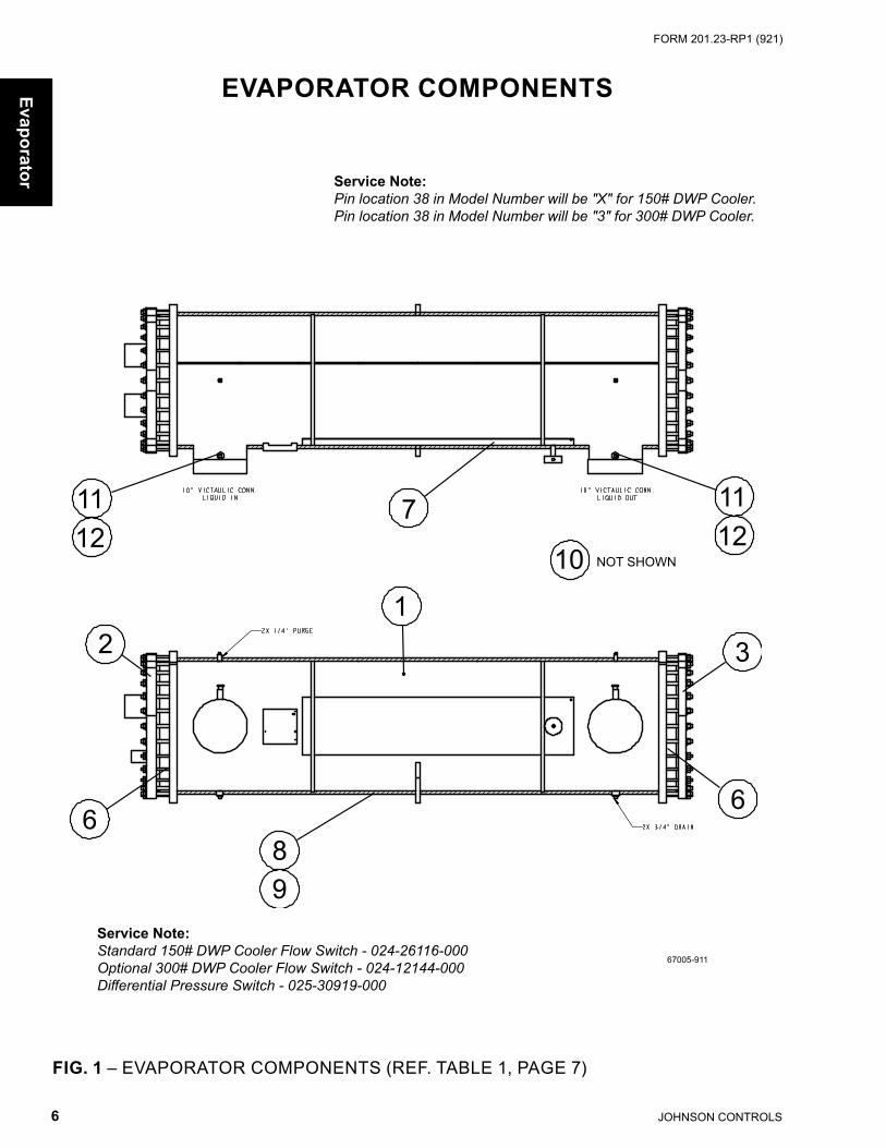
Service Note: Standard 150# DWP Cooler Flow Switch - 024-26116-000Optional 300# DWP Cooler Flow Switch - 024-12144-000Differential Pressure Switch - 025-30919-000
FIG. 1 – EVAPORATOR COMPONENTS (REF. TABLE 1, PAGE 7)
EVAPORATOR COMPONENTS
Service Note: Pin location 38 in Model Number will be "X" for 150# DWP Cooler.Pin location 38 in Model Number will be "3" for 300# DWP Cooler.
Evaporator
67005-911

JOHNSON CONTROLS 7
FORM 201.23-RP1 (921)
EVAPORATOR COMPONENTS (CONT'D)RIGHT HANDED
Evap
orat
or
TABLE 1 – EVAPORATOR COMPONENTS - PIN #9 = 'S OR P' (SEE FIG. 1, PAGE 6)
ITEM #
QTYPERUNIT
DESCRIPTION DWP UNIT MODEL YCIV0600
UNIT MODELSYCIV0650
AND YCIV0720
UNIT MODELSYCIV0770, 0840, 0920
AND YCIV1000
1 1
Evaporator, Fully Insulatedwith Heater
ALL375-67011-991 375-67007-991 375-67005-991
Evaporator, less Heater& Insulation 375-67011-990 375-67007-000 375-67005-000
2 1 Head, Connection End ALL 075-54517-000 075-54488-000 075-53210-0003 1 Head, Back End ALL 075-54515-000 075-54486-000 075-53206-0004 1 Baffle, Connection End ALL 075-54519-000 075-54490-000 075-65302-0005 1 Baffle, Back End ALL 075-54514-000 075-54485-000 075-65302-0006 2 Gasket, Baffle and Head ALL 075-54520-000 075-54491-000 075-54103-0007 2 Heater, Cooler 280 Watt ALL 025-22691-000 025-22691-000 025-22691-0008 - Insulation (3/4"x49"x65")
ALL010-05997-000 010-05997-000 010-05997-000
9 - Insulation (1 1/2"x49"x65") 010-05998-000 010-05998-000 010-05998-00010 1 qt. Adhesive (Use with #6) ALL 013-03311-00011 2 Sensor, Water Temperature ALL 025-40334-000 025-40334-000 025-40334-00012 2 Well, Thermo ALL 026-33627-000 026-33627-000 026-33627-000
ITEM #
QTYPERUNIT
DESCRIPTION DWP
UNIT MODELS YCIV0590, 0630 AND YCIV0700
UNIT MODELSYCIV0760, 0800 AND YCIV0830
UNIT MODELYCIV0930
1 1
Evaporator, Fully Insulatedwith Heater
ALL375-67007-991 375-67009-991 375-67005-991
Evaporator, less Heater& Insulation 375-67007-000 375-67009-990 375-67005-000
2 1 Head, Connection End ALL 075-54488-000 075-53794-000 075-53210-0003 1 Head, Back End ALL 075-54486-000 075-53796-000 075-53206-0004 1 Baffle, Connection End ALL 075-54490-000 075-53790-000 075-65302-0005 1 Baffle, Back End ALL 075-54485-000 075-53792-000 075-65302-0006 2 Gasket, Baffle and Head ALL 075-54491-000 075-53797-000 075-54103-0007 2 Heater, Cooler 280 Watt ALL 025-22691-000 025-22691-000 025-22691-0008 - Insulation (3/4"x49"x65")
ALL010-05997-000 010-05997-000 010-05997-000
9 - Insulation (1 1/2"x49"x65") 010-05998-000 010-05998-000 010-05998-00010 1 qt. Adhesive (Use with #6) ALL 013-03311-00011 2 Sensor, Water Temperature ALL 025-40334-000 025-40334-000 025-40334-00012 2 Well, Thermo ALL 026-33627-000 026-33627-000 026-33627-000
TABLE 1 (CONT'D) – EVAPORATOR COMPONENTS - PIN #9 = 'E OR V'(SEE FIG. 1, PAGE 6)

JOHNSON CONTROLS8
FORM 201.23-RP1 (921)
This page is intentionally left blank

JOHNSON CONTROLS 9
FORM 201.23-RP1 (921)
FIG. 2 – CONDENSER COIL COMPONENTS(REF. TABLE 2, PAGES 10 AND 11)
25578-1
2
3
4
1
Con
dens
er
CONDENSER COIL COMPONENTS
POWER PANEL END OFCHILLER

JOHNSON CONTROLS10
FORM 201.23-RP1 (921)
TABLE 2 – CONDENSER COIL COMPONENTS (SEE FIG. 2, PAGE 9)
ITEMNUMBER DESCRIPTION SYSTEM QTY
MODELSYCIV0590, 0600 AND YCIV0650
MODELSYCIV0630, 0720 AND YCIV0770
MODELSYCIV0700, 0760 AND YCIV0840
ALUMINUM FIN COILS - 'PIN 45 = X'1
Coil Assembly*Sys 1
1 375-55356-001 375-55350-001 375-55350-0012 1 375-55356-002 375-55350-002 375-55350-0023
Sys 21 375-55356-003 375-55356-003 375-55350-003
4 1 375-55356-004 375-55356-004 375-55350-004COPPER COILS - 'PIN 45 = C'
1
Coil Assembly*Sys 1
1 375-55356-005 375-55350-005 375-55350-0052 1 375-55356-006 375-55350-006 375-55350-006
3Sys 2
1 375-55356-007 375-55356-007 375-55350-007
4 1 375-55356-008 375-55356-008 375-55350-008
BLACK FIN COILS - 'PIN 45 = B'1
Coil Assembly*Sys 1
1 375-55356-009 375-55350-009 375-55350-009
2 1 375-55356-010 375-55350-010 375-55350-010
3Sys 2
1 375-55356-011 375-55356-011 375-55350-011
4 1 375-55356-012 375-55356-012 375-55350-012
PHENOLIC COILS - 'PIN 45 = P'1
Coil Assembly*Sys 1
1 375-58328-001 375-58328-005 375-58328-005
2 1 375-58328-002 375-58328-006 375-58328-006
3Sys 2
1 375-58328-003 375-58328-003 375-58328-007
4 1 375-58328-004 375-58328-004 375-58328-008
EPOXY COILS - 'PIN 45 = E'1
Coil Assembly*Sys 1
1 375-67025-009 375-67024-009 375-67024-009
2 1 375-67025-010 375-67024-010 375-67024-010
3Sys 2
1 375-67025-011 375-67025-011 375-67024-011
4 1 375-67025-012 375-67025-012 375-67024-012
Condenser
CONDENSER COIL COMPONENTS (CONT’D)
*Note: Coil Assembly includes coil and headers.

JOHNSON CONTROLS 11
FORM 201.23-RP1 (921)
CONDENSER COIL COMPONENTS (CONT’D)
ITEMNUMBER DESCRIPTION SYSTEM QTY
MODELSYCIV0800 AND
YCIV0920
MODELSYCIV0830, 0930 AND YCIV1000
ALUMINUM FIN COILS - 'PIN 45 = X'1
Coil Assembly*Sys 1
1 375-54395-001 375-54395-0012 1 375-54395-002 375-54395-0023
Sys 21 375-55350-003 375-54395-003
4 1 375-55350-004 375-54395-004COPPER COILS - 'PIN 45 = C'
1
Coil Assembly*Sys 1
1 375-54395-005 375-54395-0052 1 375-54395-006 375-54395-006
3Sys 2
1 375-55350-007 375-54395-007
4 1 375-55350-008 375-54395-008
BLACK FIN COILS - 'PIN 45 = B'1
Coil Assembly*Sys 1
1 375-54395-009 375-54395-009
2 1 375-54395-010 375-54395-010
3Sys 2
1 375-55350-011 375-54395-011
4 1 375-55350-012 375-54395-012
PHENOLIC COILS - 'PIN 45 = P'1
Coil Assembly*Sys 1
1 375-58328-009 375-58328-009
2 1 375-58328-010 375-58328-010
3Sys 2
1 375-58328-007 375-58328-011
4 1 375-58328-008 375-58328-012
EPOXY COILS - 'PIN 45 = E'1
Coil Assembly*Sys 1
1 375-67016-009 375-67016-009
2 1 375-67016-010 375-67016-010
3Sys 2
1 375-67024-011 375-67016-011
4 1 375-67024-012 375-67016-012
TABLE 2 (CONT'D) – CONDENSER COIL COMPONENTS (SEE FIG. 2, PAGE 9)
*Note: Coil Assembly includes coil and headers.C
onde
nser

JOHNSON CONTROLS12
FORM 201.23-RP1 (921)
FAN COMPONENTS
Fans
55596-000
Service Note: Fan Hub to Shaft Joint should besealed with protective coating - useRUST VETO 344 - a solvent type,rust preventative coating.
FIG. 3 – FAN COMPONENTS
TABLE 3 – FAN COMPONENTS
Service Note: Pin Location 52 in Model Number will be “X” for Standard Fan or “L” for Low Sound Fan. See page 4.
S = Recommended Spare Parts
ITEMNUMBER DESCRIPTION VOLTAGE
CODE
FAN TYPESTANDARD LOW
NOISE 7/8", 950 RPM
ULTRA LOW NOISE7/8", 690 RPM
1sMotor, Fan
2 HP(YCIV0590-YCIV1000)
-50 024-27322-107 024-34980-003
2s Blade -50 026-41943-000 026-45549-0003 Guard -50 026-35605-0014 Orifice -50 026-41609-0005 Support -50 026-41937-000 026-41938-0006 Support Ring -50 026-36367-0007 Spacer (.375 I.D.) -50 075-29007-0008 Screw, Cap (M8x125) -50 021-18494-0009 Spacer (1.406 I.D.) -50 075-40484-000
10 Hub, Square -50 026-41939-001 (1.000") 026-41939-005 (1.125")
97
8
3
2
4
110
65

JOHNSON CONTROLS 13
FORM 201.23-RP1 (921)
FAN COMPONENTS (CONT'D)
67027-002
Service Note: Fan Hub to Shaft Joint should besealed with protective coating - useRUST VETO 344 - a solvent type,rust preventative coating.
FIG. 3A – FAN COMPONENTS
TABLE 3A – FAN COMPONENTS
Service Note: Pin Location 52 in Model Number will be “H” for High Static Fan or “T” for Two Speed Fan. See page 4.
S = Recommended Spare Parts
ITEMNUMBER DESCRIPTION VOLTAGE
CODE
FAN TYPEHIGH STATIC7/8", 950 RPM
TWO SPEED*7/8", 490/660 RPM
1sMotor, Fan
5 HP(YCIV0590-YCIV1000)
-50 024-36081-003 024-36092-004
2s Blade -50 026-43982-000 026-45045-0003 Guard -50 026-35605-0014 Orifice -50 026-41609-0005 Support -50 026-67014-000 026-67028-0006 Support Ring -50 N/A 026-36367-0007 Spacer -50 075-40485-000 075-70345-0008 Screw, Cap -50 021-17791-000 021-18494-0009 Spacer -50 075-67017-000 075-29007-000
10 Hub, Square -50 N/A 026-41939-005 (1.125")
1
2
5
79
8
34
*Note: Refer to Figure 3 on page 12 for the Two Speed Fan components.

JOHNSON CONTROLS14
FORM 201.23-RP1 (921)
FIG. 4 – PIPING COMPONENTS - MODEL YCIV0590 & YCIV0630 SHOWN (REF. TABLE 4, PAGES 15, 16 AND 17)
REFRIGERANT PIPING COMPONENTSCHILLER MODEL YCIV
Piping66920-001
Suction Line Service Valve Option
Piping - Suction, Discharge, Oil And Liquid Line
124
20
11A
14A
18B
14B
1919
5 8
8
9
15
11B
3
16
12A
12B
10
67
13
17
18A

JOHNSON CONTROLS 15
FORM 201.23-RP1 (921)
Pipi
ng
REFRIGERANT PIPING COMPONENTS (CONT’D)CHILLER MODEL YCIV
TABLE 4 – REFRIGERANT PIPING COMPONENTS (SEE FIG. 4, PAGE 14)
S = Recommended Spare Parts
ITEMNO.
QTYPERUNIT
DESCRIPTIONYCIV0590 AND
YCIV0630375-66920-000
YCIV0600375-66921-000
YCIV0650, 0700 AND YCIV0730375-66922-000
1s 4 Valve, Electronic Expansion 025-41565-000 025-41565-000 025-41565-0002 2 Valve, Low Side Relief - 235# 022-11312-000 022-11312-000 022-11312-0003 2 Valve, Economizer Solenoid 025-40330-000 025-40330-000 025-40330-0004 2 Dehydrator, Body (Replacable Core) 026-16960-000 026-16960-000 026-16960-000
5s 6 Core, Dehydrator 026-37540-000 026-37540-000 026-37540-0006 4 Moisture Indicator, Body 026-32399-000 026-32399-000 026-32399-0007 4 Moisture Indicator, Sight Glass Cap 026-32800-000 026-32800-000 026-32800-0008 2 Valve, Liquid Stop 022-09779-000 022-09779-000 022-09779-0009 2 Compressor, MTS See page 21
10 4 Valve, Charging 022-09754-000 022-09754-000 022-09754-00011A 2 Muffler (System 1) 375-55738-000 375-55738-000 375-55738-00011B 2 Muffler (System 2) 375-55738-000 375-55738-000 375-53202-00012A 1 Oil Separator (Left) 026-42901-99112B 1 Oil Separator (Right) 026-42901-99212D 2 Sight Glass, Oil Separator (All) 026-43375-00012E 2 O-ring, Sight Glass 028-15574-00013 2 Valve, Ball (Oil Line) 022-09172-000 022-09172-000 022-09172-000
14A 1 Ball Valve, Discharge (System 1) 022-11326-000 022-11326-000 022-11326-00014B 1 Ball Valve, Discharge (System 2) 022-11326-000 022-11326-000 022-11325-000
152 Valve, Angle 022-11358-000 022-11358-000 022-11358-0002 1 1/2" Gasket 028-15296-000 028-15296-000 028-15296-000
16 2 Flash Tank 375-65618-990 375-65618-990 375-65618-99017 4 Valve, Relief 022-11398-000 022-11398-000 022-11398-000
18A 1 Ball Valve, Suction (System 1) 022-11693-000 022-11693-000 022-11693-00018B 1 Ball Valve, Suction (System 2) 022-11693-000 022-11693-000 022-11693-000
192 Valve, Stop 022-02845-001 022-02845-001 022-02845-0012 3 1/2" Gasket 028-13974-000 028-13974-000 028-13974-000
20s 2 Sensor, Refrig Level 025-40274-000 025-40274-000 025-40274-000
**Straight Flow Drain or Feed
Valve
*90º Flow Drain or Feed
Valve

JOHNSON CONTROLS16
FORM 201.23-RP1 (921)
Piping
REFRIGERANT PIPING COMPONENTS (CONT’D)CHILLER MODEL YCIV
TABLE 4 (CONT'D) – REFRIGERANT PIPING COMPONENTS (SEE FIG. 4, PAGE 14)
ITEMNO.
QTYPERUNIT
DESCRIPTIONYCIV0760, 0800 AND YCIV0830375-65716-000
YCIV0775 AND YCIV0840
375-66924-000
YCIV0920 AND YCIV0930
375-66925-0001s 4 Valve, Electronic Expansion 025-41565-000 025-41565-000 025-41565-0002 2 Valve, Relief 022-11312-000 022-11312-000 022-11312-0003 2 Valve, Solenoid 025-40330-000 025-40330-000 025-40330-0004 2 Dehydrator, Body (Replacable Core) 026-16960-000 026-16960-000 026-16960-000
5s 6 Core, Dehydrator 026-37540-000 026-37540-000 026-37540-0006 4 Moisture Indicator, Body 026-32399-000 026-32399-000 026-32399-0007 4 Moisture Indicator, Sight Glass Cap 026-32800-000 026-32800-000 026-32800-0008 2 Valve, Liquid Stop 022-09779-000 022-09779-000 022-09779-0009 2 Compressor See page 21
10 4 Valve, Charging 022-09754-000 022-09754-000 022-09754-00011 2 Muffler 375-53202-000 375-53202-000 375-53202-000
12A 2 Oil Separator (Left) 026-42901-99112B 2 Oil Separator (Right) 026-42901-99212D 2 Sight Glass, Oil Separator (All) 026-43375-00012E 2 O-ring, Sight Glass 028-15574-00013 2 Valve, Ball (Oil Line) 022-09172-000 022-09172-000 022-09172-000
14A 1 Ball Valve, Discharge (System 1) 022-11325-000 022-11325-000 022-11325-00014B 1 Ball Valve, Discharge (System 2) 022-11325-000 022-11325-000 022-11325-000
152 Valve, Angle 022-11358-000 022-11358-000 022-11358-0002 1 1/2" Gasket 028-15296-000 028-15296-000 028-15296-000
16 2 Flash Tank 375-65618-990 375-65618-990 375-65618-99017 2 Valve, Relief 022-11398-000 022-11398-000 022-11398-000
18A 1 Ball Valve, Suction (System 1) 022-11693-000 022-11693-000 022-11693-00018B 1 Ball Valve, Suction (System 2) 022-11693-000 022-11693-000 022-11694-000
192 Valve, Stop 022-02845-001 022-02845-001 022-02845-0012 3 1/2" Gasket 028-13974-000 028-13974-000 028-13974-000
20s 2 Sensor, Refrig Level 025-40274-000 025-40274-000 025-40274-000
S = Recommended Spare Parts
**Straight Flow Drain or Feed
Valve
*90º Flow Drain or Feed
Valve

JOHNSON CONTROLS 17
FORM 201.23-RP1 (921)
Pipi
ng
REFRIGERANT PIPING COMPONENTS (CONT’D)CHILLER MODEL YCIV
TABLE 4 (CONT'D) – REFRIGERANT PIPING COMPONENTS (SEE FIG. 4, PAGE 14)
S = Recommended Spare Parts
ITEMNO.
QTYPERUNIT
DESCRIPTION YCIV1000375-66910-000
1s 4 Valve, Electronic Expansion 025-41565-0002 2 Valve, Relief 022-11312-0003 2 Valve, Solenoid 025-40330-0004 2 Dehydrator, Body (Replacable Core) 026-16960-000
5s 6 Core, Dehydrator 026-37540-0006 4 Moisture Indicator, Body 026-32399-0007 4 Moisture Indicator, Sight Glass Cap 026-32800-0008 2 Valve, Liquid Stop 022-09779-0009 2 Compressor See page 21
10 4 Valve, Charging 022-09754-00011 2 Muffler 375-53202-000
12A 2 Oil Separator (Left) 026-42901-99112B 2 Oil Separator (Right) 026-42901-99212D 2 Sight Glass, Oil Separator (All) 026-43375-00012E 2 O-ring, Sight Glass 028-15574-00013 2 Valve, Ball (Oil Line) 022-09172-000
14A 1 Ball Valve, Discharge (System 1) 022-11325-00014B 1 Ball Valve, Discharge (System 2) 022-11325-000
152 Valve, Angle 022-11358-0002 1 1/2" Gasket 028-15296-000
16 2 Flash Tank 375-65618-99017 2 Valve, Relief 022-11398-000
18A 1 Ball Valve, Suction (System 1) 022-11694-00018B 1 Ball Valve, Suction (System 2) 022-11694-000
192 Valve, Stop 022-02845-0012 3 1/2" Gasket 028-13974-000
20s 2 Sensor, Refrig Level 025-40274-000
**Straight Flow Drain or Feed
Valve
*90º Flow Drain or Feed
Valve

JOHNSON CONTROLS18
FORM 201.23-RP1 (921)
Piping
GLYCOL LOOP COMPONENTSCHILLER MODEL YCIV
FIG. 4A – GLYCOL LOOP COMPONENTS (REF. TABLE 4A, PAGE 19)
HOSE, BLACK RUBBER - 3/4 I.D.(028-11958-000)
SECTION LENGTH
1 41"2 41"3 50"4 50"5 52"6 43"7 59"8 143"9 91"
66905-001a
17
6 5
2
10
11
15
15
15
18
1715
16
14
1912
9
8
43

JOHNSON CONTROLS 19
FORM 201.23-RP1 (921)
TABLE 4A (CONT'D) – GLYCOL LOOP COMPONENTS (SEE FIG. 4A, PAGE 18)
S = Recommended Spare Parts* For All Europe-bound YCIV chiller built after October 7th, 2015, the Coolant / Glycol charged into VSD cooling system is European compliant Dowcal 200 (013-03849-001), for either service or maintenance purpose, top-off or replace the coolant with "Dowcal 200" only; for YCIV chiller built before that day, Dowfrost HD (013-03344-000) was charged, for topping-up just use Dow-frost HD, however, for maintenance, replace the coolant by either "Dowcal 200" or "Dowfrost HD" but do not mix them.For all other regions, Use Dowfrost HD (013-03344-000) only.
ITEMNO.
QTYPERUNIT
DESCRIPTION PART NUMBER
10s 1 CAP, RADIATOR 023-21927-00011 1 TUBE, GLYCOL 075-55649-000
12 1PUMP, SINGLE STAGE (60 HERTZ) 026-41611-000PUMP, SINGLE STAGE (50 HERTZ) 026-41611-001
13s 5 galCOOLANT PG (5 GALLON), NON EU COMPLIANT* 013-03344-000
COOLANT PG (5 GALLON), EU COMPLIANT 013-03849-00114 1 REDUCER 023-21941-00015 4 FITTING, HOSE BARB 023-21929-00016 1 TEE 023-22526-00017 1 BUSHING 023-21934-00018 1 BUSHING 023-21935-00019 1 VALVE, DRAIN 023-21874-000
Pipi
ng
GLYCOL LOOP COMPONENTS (CONT’D)CHILLER MODEL YCIV
† Note:VSD cooling system capacity ≈ 3.5 gallons. Fill level when cold = 9"-15" below cap.
Caution:Mixing different types of Glycol or the addition of water may cause permanent damage to the cooling system.

JOHNSON CONTROLS20
FORM 201.23-RP1 (921)
COMPRESSOR MODEL NOMENCLATURE
Com
pressor
MTS 45 S A A D 46
Type of YORK Semi-Hermetic Screw Compressor VSD Driven Diameter of Male Rotor 45 = 145.3 mm 36 = 136.4 mm 24 = 124.0 mm Compressor Rotor Length L = Length L/D S = Short L/D
Voltage and Frequency 46 = 460-3-200
Motor Stack & Diameter Code D = 8-3/4 Dia. x 8-3/4 Stack
Motor Vendor A = 4-Pole A.O. Smith
Design Series A
COMPRESSOR WEIGHTSMM SIZE WEIGHT (LBS.)* WEIGHT (Kg.)
145 1310 594136 1250 567124 1175 533112 760 345
*Note: Less Service Valves.
ITEM REF. DESCRIPTION 5 GALLONOILs R-134A Oil, Type 'L' (Synthetic) 011-00592-000
S = Recommended Spare Parts
DESCRIPTION 5 GALLONCompressor Heater 025-32938-000

JOHNSON CONTROLS 21
FORM 201.23-RP1 (921)
Com
pres
sor
COMPRESSORTABLE 5 – STANDARD MODEL COMPRESSOR PART NUMBERS - S OR P
MODEL VOLTAGE CODE
SYSTEM #1 COMPRESSOR SYSTEM #2 COMPRESSORPART # MODEL # MM QTY PART # MODEL # MM QTY
YCIV0590 -50 364-50820-100 MTS24SA 124 1 364-50820-100 MTS24SA 124 1
YCIV0600 -50 364-50820-100 MTS24SA 124 1 364-50820-100 MTS24SA 124 1
YCIV0630 -50 364-50820-100 MTS24SA 124 1 364-50820-100 MTS24SA 124 1
YCIV0650 -50 364-50821-100 MTS36SA 136 1 364-50820-100 MTS24SA 124 1
YCIV0700 -50 364-50821-100 MTS36SA 136 1 364-50820-100 MTS24SA 124 1
YCIV0720 -50 364-50821-100 MTS36SA 136 1 364-50820-100 MTS24SA 124 1
YCIV0760 -50 364-50821-100 MTS36SA 136 1 364-50821-100 MTS36SA 136 1
YCIV0770 -50 364-50821-100 MTS36SA 136 1 364-50821-100 MTS36SA 136 1
YCIV0800 -50 364-50821-100 MTS36SA 136 1 364-50821-100 MTS36SA 136 1
YCIV0830 -50 364-50821-100 MTS36SA 136 1 364-50821-100 MTS36SA 136 1
YCIV0840 -50 364-50821-100 MTS36SA 136 1 364-50821-100 MTS36SA 136 1
YCIV0920 -50 364-50822-100 MTS45SA 145 1 364-50821-100 MTS36SA 136 1
YCIV0930 -50 364-50822-100 MTS45SA 145 1 364-50821-100 MTS36SA 136 1
YCIV1000 -50 364-50822-100 MTS45SA 145 1 364-50822-100 MTS45SA 145 1
COMPRESSOR CHANGE OUT PARTSMM SIZE DESCRIPTION PART NUMBER
All
Heater, Compressor (350 watts) 025-32938-000Filter, Oil 026-35601-000
O-ring, Filter Cover 028-13849-000Gasket, Suction Flange 028-15075-159
Gasket, Discharge Flange 028-15296-000Seal, HPCO O-Ring 028-13540-000

JOHNSON CONTROLS22
FORM 201.23-RP1 (921)
CONTROL AND VSD PANEL CONFIGURATIONS
PIN 16 & 17LETTER CODEIDENTIFIERS
OPTION PANEL AND POWER PANEL CONFIGURATIONS
S X Single Point Supply Terminal BlockB X Single Point Supply Circuit BreakerS S Single Point Supply Terminal Block w/ Separate System Non-Fused Disconnect SwitchC S Single Point Supply Circuit Breaker w/ Separate System Non-Fused Disconnect Switch
Power panels and option panels are offered in several different configurations using three (3) major components:
1. TERMINAL BLOCKS2. CIRCUIT BREAKERS3. NON-FUSED DISCONNECT SWITCHES
The most basic chiller power wiring configuration uses TERMINAL BLOCKS in the power panels, and an options panel with no power wire termination hardware. See figures on previ-ous page. The model pin number locations 16 and 17 would be X and X to reflect this basic combination. Identify model pin number locations 16 and 17 to identify the chiller power wiring connections and hardware listed below.
FIG. 5 – CONTROL, OPTIONS AND POWER PANELS LAYOUT
Variable Speed Drive

JOHNSON CONTROLS 23
FORM 201.23-RP1 (921)
FIG. 5A – EXAMPLES OF POWER WIRING CONFIGURATIONS (2-COMPRESSOR UNITS)
CONTROL AND VSD PANEL CONFIGURATIONS (CONT'D)
Varia
ble
Spee
d D
rive
*Note: On units with Single Point Terminal Blocks, the terminal blocks are located in the same space as the Single Point Circuit Breaker shown in Fig. 5A.

JOHNSON CONTROLS24
FORM 201.23-RP1 (921)
VARIABLE SPEED DRIVE PANEL COMPONENTS
Variable Speed Drive
FIG. 5B – VSD / CONTROL PANEL IDENTIFIER LOCATION (2-COMPRESSOR UNITS)
PANEL NAMEPLATE

JOHNSON CONTROLS 25
FORM 201.23-RP1 (921)
VARIABLE SPEED DRIVE PANEL COMPONENTS (CONT’D)
Varia
ble
Spee
d D
rive
VSD / Control Panel Part Numbers for Models YCIV0590 thru YCIV0840
Voltage Code Qty
Standard, Ultra Quiet or Two Speed FansSingle Point Terminal Block Single Point Circuit Breaker
No Ambient Kit, Temp. Reset/Offset and/or
Current Reset/Offset
E-Link Gateway
No Ambient Kit, Temp. Reset/Offset and/or
Current Reset/Offset
E-Link Gateway
17
1
N/A N/A N/A N/A28 N/A N/A N/A N/A40 371-04178-603 371-04178-615 371-04178-609 371-04178-62146 371-04178-105 371-04178-117 371-04178-111 371-04178-12350 371-04178-604 371-04178-616 371-04178-610 371-04178-62258 N/A N/A N/A N/A
Voltage Code Qty
High Static FansSingle Point Terminal Block Single Point Circuit Breaker
No Ambient Kit, Temp. Reset/Offset and/or
Current Reset/Offset
E-Link Gateway
No Ambient Kit, Temp. Reset/Offset and/or
Current Reset/Offset
E-Link Gateway
17
1
N/A N/A N/A N/A28 N/A N/A N/A N/A40 371-04178-623 371-04178-627 371-04178-625 371-04178-62946 371-04178-129 371-04178-141 371-04178-135 371-04178-14750 371-04178-624 371-04178-628 371-04178-626 371-04178-63058 N/A N/A N/A N/A
TABLE 7 – VSD / CONTROL PANEL IDENTIFIERS (TO IDENTIFY REPLACEMENT PART NUMBERS, SELECT PANEL IDENTIFIER NUMBER FROM THE TABLES BELOW, THEN REFER TO THE 'VSD/CONTROL PANEL COMPONENTS' TABLES, PAGES 31-39 AND FIGURE 5B ON PAGE 24)

JOHNSON CONTROLS26
FORM 201.23-RP1 (921)
VARIABLE SPEED DRIVE PANEL COMPONENTS (CONT'D)
Variable Speed Drive
TABLE 7 (CONT'D) – VSD / CONTROL PANEL IDENTIFIERS (TO IDENTIFY REPLACEMENT PART NUMBERS, SELECT PANEL IDENTIFIER NUMBER FROM THE TABLES BELOW, THEN REFER TO THE 'VSD/CONTROL PANEL COMPONENTS' TABLES, PAGES 31-39 AND FIGURE 5B ON PAGE 24)
VSD / Control Panel Part Numbers for Models YCIV0920 thru YCIV1000
Voltage Code Qty
Standard, Ultra Quiet or Two Speed FansSingle Point Terminal Block Single Point Circuit Breaker
No Ambient Kit, Temp. Reset/Offset and/or
Current Reset/Offset
E-Link Gateway
No Ambient Kit, Temp. Reset/Offset and/or
Current Reset/Offset
E-Link Gateway
17
1
N/A N/A N/A N/A28 N/A N/A N/A N/A40 371-04178-703 371-04178-715 371-04178-709 371-04178-72146 371-04178-105 371-04178-117 371-04178-111 371-04178-12350 371-04178-704 371-04178-716 371-04178-710 371-04178-72258 N/A N/A N/A N/A
Voltage Code Qty
High Static FansSingle Point Terminal Block Single Point Circuit Breaker
No Ambient Kit, Temp. Reset/Offset and/or
Current Reset/Offset
E-Link Gateway
No Ambient Kit, Temp. Reset/Offset and/or
Current Reset/Offset
E-Link Gateway
17
1
N/A N/A N/A N/A28 N/A N/A N/A N/A40 371-04178-723 371-04178-727 371-04178-725 371-04178-72946 371-04178-129 371-04178-141 371-04178-135 371-04178-14750 371-04178-724 371-04178-728 371-04178-726 371-04178-73058 N/A N/A N/A N/A

JOHNSON CONTROLS 27
FORM 201.23-RP1 (921)
Varia
ble
Spee
d D
rive
FIG
. 6 –
VA
RIA
BLE
SP
EE
D D
RIV
E C
OM
PO
NE
NTS
(RE
F. 'C
OM
MO
N P
AR
TS' T
AB
LE 8
,PA
GE
31
AN
D V
AR
IAB
LE P
AR
TS T
AB
LE 8
A, P
AG
ES
32-
39)
0417
8-04
0417
8-5a 04
178-
4b
##
= VA
RIA
BLE
PAR
TS
= C
OM
MO
N P
ARTS
* #=
OBS
OLE
TED
PAR
TS
VARIABLE SPEED DRIVE PANEL COMPONENTS (CONT’D)

JOHNSON CONTROLS28
FORM 201.23-RP1 (921)
0417
8-06
Variable Speed Drive
FIG
. 6A
– V
AR
IAB
LE S
PE
ED
DR
IVE
CO
MP
ON
EN
TS (R
EF.
'CO
MM
ON
PA
RTS
' TA
BLE
8,
PAG
E 3
1 A
ND
VA
RIA
BLE
PA
RTS
TA
BLE
8A
, PA
GE
S 3
2-39
)
##
= VA
RIA
BLE
PAR
TS
= C
OM
MO
N P
ARTS
* #=
OBS
OLE
TED
PAR
TS
VARIABLE SPEED DRIVE PANEL COMPONENTS (CONT’D)
JOHNSON CONTROLS 29
FORM 201.23-RP1 (921)
VARIABLE SPEED DRIVE PANEL COMPONENTS (CONT’D)
Varia
ble
Spee
d D
rive
55832-000C
331-03478-002
025-43893-000
E-Link
04178-06d
04178-06b
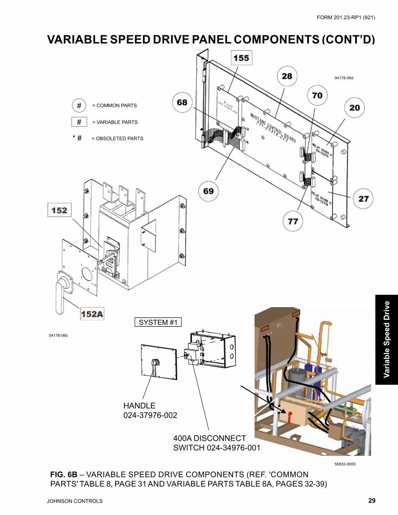
FIG. 6B – VARIABLE SPEED DRIVE COMPONENTS (REF. 'COMMON PARTS' TABLE 8, PAGE 31 AND VARIABLE PARTS TABLE 8A, PAGES 32-39)
#
#
= VARIABLE PARTS
= COMMON PARTS
* # = OBSOLETED PARTS
400A DISCONNECTSWITCH 024-34976-001
HANDLE024-37976-002
SYSTEM #1

JOHNSON CONTROLS30
FORM 201.23-RP1 (921)
Variable Speed Drive
04178-05
VARIABLE SPEED DRIVE PANEL COMPONENTS (CONT'D)
FIG. 6C – VARIABLE SPEED DRIVE COMPONENTS (REF. 'COMMON PARTS' TABLE 8, PAGE 31 AND VARIABLE PARTS TABLE 8A, PAGES 32-39)
#
#
= VARIABLE PARTS
= COMMON PARTS
* # = OBSOLETED PARTS

JOHNSON CONTROLS 31
FORM 201.23-RP1 (921)
VARIABLE SPEED DRIVE PANEL COMPONENTS (CONT’D)
Varia
ble
Spee
d D
rive
TABLE 8 – VARIABLE SPEED DRIVE COMMON PARTS (SEE. FIGS. 6-6C, PAGES 27-30)ITEM
NUMBERQUANTITY PER
UNIT DESCRIPTION YORK PARTNUMBER
5 1 RELAY, PUMP / FAN 024-30441-0007 3 TRANSFORMER, 75VA (3T, 10T, 11T) 025-27911-000
15 5 FUSE HOLDER, 1 POLE - 30A 025-39951-00017 1 VOLTAGE SUPPRESSION BOARD 031-02453-00020 1 RELAY BOARD #1 031-02479-00122 12 RESISTOR (R3-R14) 025-35953-00023 6 CAPACITOR (C13-C18) 025-39806-00024 1 WIRING KIT, DVDT 571-04178-21125 12 PAD, THERMAL 028-15299-00027 1 RELAY BOARD #2 031-02479-002
28s 1 CHILLER CONTROL BOARD Superseded by 331-03478-xxx 331-03478-002
28A1
Only for use with 031-02478-002
SD CARD WITH SOFTWARE (STANDARD) 031-03476-001SD CARD WITH SOFTWARE (OPTIMIZED) 031-03476-002
BLANK SD CARD 031-03466-000
28B 1
CHILLER CONTROL BOARD with Program CardSTANDARD IPLV 3,4 COMPRESSOR 331-03478-601STANDARD IPLV 2 COMPRESSOR 331-03478-602
OPTIMIZED IPLV 3,4 COMPRESSOR 331-03478-603OPTIMIZED IPLV 2 COMPRESSOR 331-03478-604
31 1 BUS ISOLATION BOARD 031-01624-00032 1 GASKET, FIELD POWER 028-15246-00033 1 GASKET, CUSTOMER CONNECTIONS 028-15247-00034 1 GASKET, CIRCUIT BREAKER 028-15248-00035 1 GASKET, AUTO TRANSFORMER 028-15249-00036 1 GASKET, KEYPAD / DISPLAY 028-15250-00037 1 GASKET, COIL 028-15251-00059 1 EPROM, PWM GENERATOR U39 031-02522-001*
59a 1 EPROM, LOGIC BOARD U36 (obsolete) 031-02521-001**59b 1 PROM, FPGA U41 (obsolete) 031-02523-001**59c 1 EPROM, LOGIC BOARD U39 (obsolete) 031-02522-001**
61 1 KEYPAD, LATITUDE 024-34930-000***1 OVERLAY, KEYPAD (ENGLISH) 024-34930-001***
62 1 DISPLAY, LATITUDE 031-02508-00063 1 SWITCH, ON / OFF 024-34951-00068 1 CABLE, RIBBON (DISPLAY) 571-04178-26169 1 CABLE, RIBBON (KEYPAD) 571-04178-26270 1 CABLE, RIBBON (RELAY BOARD #1) 571-04178-263
72s 1 CONTROLLER, DRAIN/FEED (90º FLOW) 031-02510-000****1 CONTROLLER, DRAIN/FEED (STRAIGHT FLOW) 031-02742-000****
77 1 CABLE, RIBBON (RELAY BOARD #2) 571-04178-26488 3 FUSES (11FU, 12FU, 13FU) 025-38523-00092 1 FUSE, 15A (18FU) 025-34141-00093 1 FUSE, 20A (17FU) 025-35908-00094 3 FUSE, 6A (20FU, 21FU) 025-35902-000
* Note: Used on new 031-02507-000 VSD Logic Board.** Note: Only used on obsolete 031-02477--000 VSD Logic Board (no longer available).*** Note: Both the keypad and overlay must be replaced when replacing the keypad.**** Note: See page 20 for valve type to aid in identifying the controller.

JOHNSON CONTROLS32
FORM 201.23-RP1 (921)
TAB
LE 8
A –
VA
RIA
BLE
SP
EE
D D
RIV
E C
OM
PO
NE
NTS
(SE
E. F
IGS
. 6-6
C, P
AG
ES
27-
30)
VARIABLE SPEED DRIVE PANEL COMPONENTS (CONT'D)
Variable Speed Drive
Item
N
umbe
rD
escr
iptio
n37
1-04
178-
603*
-40
371-
0417
8-10
5**
-46
371-
0417
8-60
4*-5
037
1-04
178-
615*
-40
371-
0417
8-11
7**
-46
371-
0417
8-61
6*-5
0Q
tyPa
rt N
umbe
rQ
tyPa
rt N
umbe
rQ
tyPa
rt N
umbe
rQ
tyPa
rt N
umbe
rQ
tyPa
rt N
umbe
rQ
tyPa
rt N
umbe
r
151
Sing
le P
oint
Term
inal
Blo
ck K
it1
371-
0446
0-00
41
371-
0446
0-00
41
371-
0446
0-00
41
371-
0446
0-00
41
371-
0446
0-00
41
371-
0446
0-00
4
152
Sing
le P
oint
Circ
uit B
reak
er-
N/A
-N
/A-
N/A
-N
/A-
N/A
-N
/A
152A
Ope
rato
r Mec
hani
sm
(Sha
ft an
d H
andl
e)-
N/A
-N
/A-
N/A
-N
/A-
N/A
-N
/A
155
E-Li
nk G
atew
ay B
oard
-N
/A-
N/A
-N
/A1
025-
4389
3-00
01
025-
4389
3-00
01
025-
4389
3-00
0
156
Gro
und
Lugs
202
5-32
835-
000
202
5-32
835-
000
202
5-32
835-
000
202
5-32
835-
000
202
5-32
835-
000
202
5-32
835-
000
157
Indu
ctor
102
5-39
677-
000
102
5-39
677-
000
102
5-39
677-
000
102
5-39
677-
000
102
5-39
677-
000
102
5-39
677-
000
166
SCR
Trig
ger B
oard
103
1-02
060-
001
103
1-02
060-
001
103
1-02
060-
002
103
1-02
060-
001
103
1-02
060-
001
103
1-02
060-
002
167
Con
trol T
rans
form
er 2
T1
025-
4011
4-00
71
025-
4011
4-00
11
025-
4011
4-00
51
025-
4011
4-00
71
025-
4011
4-00
11
025-
4011
4-00
5
169
Coo
ling
Fan
Ass'
y1
371-
0417
9-50
21
371-
0417
9-50
21
371-
0417
9-50
41
371-
0417
9-50
21
371-
0417
9-50
21
371-
0417
9-50
4
171
Epro
m, L
ogic
Boa
rd (U
52)
103
1-02
649-
002
103
1-02
649-
001
103
1-02
649-
002
103
1-02
649-
002
103
1-02
649-
001
103
1-02
649-
002
172
VSD
Pow
er A
ssem
bly
(See
Pag
e 42
)1
371-
0418
1-10
11
371-
0418
1-10
11
371-
0418
1-10
11
371-
0418
1-10
11
371-
0418
1-10
11
371-
0418
1-10
1
173
Fan
Con
tact
or6
024-
3491
6-00
06
024-
3491
6-00
06
024-
3491
6-00
06
024-
3491
6-00
06
024-
3491
6-00
06
024-
3491
6-00
0
173A
Har
ness
, Fan
Con
tact
or1
571-
0417
8-23
11
571-
0417
8-23
11
571-
0417
8-23
11
571-
0417
8-23
11
571-
0417
8-23
11
571-
0417
8-23
1
175
Tran
sfor
mer
, Cur
rent
(Sys
. 1)
300
: 0.1
Rat
io3
025-
2117
3-00
93
025-
2117
3-00
93
025-
2117
3-00
93
025-
2117
3-00
93
025-
2117
3-00
93
025-
2117
3-00
9
176
Tran
sfor
mer
, Cur
rent
(Sys
. 2)
300
: 0.1
Rat
io
302
5-21
173-
009
302
5-21
173-
009
302
5-21
173-
009
302
5-21
173-
009
302
5-21
173-
009
302
5-21
173-
009
177
Fuse
Hol
der (
3 Po
le)
302
5-39
952-
000
302
5-39
952-
000
302
5-39
952-
000
302
5-39
952-
000
302
5-39
952-
000
302
5-39
952-
000
178
Fuse
(1FU
, 2FU
, 3FU
)3
025-
3968
1-00
03
025-
3968
1-00
03
025-
3968
1-00
03
025-
3968
1-00
03
025-
3968
1-00
03
025-
3968
1-00
0
182
Fuse
, 30A
(7-9
FU, 1
4-16
FU)
602
5-39
683-
000
602
5-39
683-
000
602
5-39
683-
000
602
5-39
683-
000
602
5-39
683-
000
602
5-39
683-
000
183
Fuse
, 10A
(4FU
, 5FU
, 19F
U)
303
1-35
906-
000
303
1-35
905-
000
303
1-35
906-
000
303
1-35
906-
000
303
1-35
905-
000
303
1-35
906-
000
190
VSD
Log
ic B
oard
103
1-02
507-
100
103
1-02
507-
000
103
1-02
507-
100
103
1-02
507-
100
103
1-02
507-
000
103
1-02
507-
100
190A
VSD
Log
ic B
oard
(Obs
olet
e)1
031-
0247
7-10
01
031-
0247
7-00
01
031-
0247
7-10
01
031-
0247
7-10
01
031-
0247
7-00
01
031-
0247
7-10
0
Serv
ice
Not
e:
Loca
te th
e PA
NE
L N
UM
BE
R n
amep
late
on
the
low
er ri
ght h
and
outs
ide
corn
er o
f the
pow
er p
anel
, th
en re
fer t
o th
e ap
prop
riate
par
ts li
st fo
r tha
t num
ber.
Or,
iden
tify
PIN
num
ber p
ositi
ons
16 a
nd 1
7 on
uni
t ide
ntifi
catio
n la
te (S
ee e
xam
ple
on P
age
4) th
en c
ompa
reto
tabl
e ab
ove
for p
ower
con
figur
atio
n op
tions
.
* Not
e: M
ust o
rder
VS
D L
ogic
Boa
rd K
it (3
31-0
2507
-602
) whe
n re
plac
ing
Logi
c B
oard
whe
n re
plac
ing
Logi
c B
oard
(031
-025
07-1
00) a
nd U
52 (0
31-0
2649
-002
). (K
it in
clud
es it
ems
59 &
171
).
** N
ote:
Mus
t ord
er V
SD
Log
ic B
oard
Kit
(331
-025
07-6
01) w
hen
repl
acin
g Lo
gic
Boa
rd w
hen
repl
acin
g Lo
gic
Boa
rd (0
31-0
2507
-000
) and
U52
(031
-026
49-0
01).
(Kit
incl
udes
item
s 59
& 1
71).

JOHNSON CONTROLS 33
FORM 201.23-RP1 (921)
VARIABLE SPEED DRIVE PANEL COMPONENTS (CONT’D)
Varia
ble
Spee
d D
rive
TAB
LE 8
A (C
ON
T'D
) – V
AR
IAB
LE S
PE
ED
DR
IVE
CO
MP
ON
EN
TS (S
EE
. FIG
S. 6
-6C
, PA
GE
S 2
7-30
)
Item
N
umbe
rD
escr
iptio
n37
1-04
178-
609*
-40
371-
0417
8-11
1**
-46
371-
0417
8-61
0*-5
037
1-04
178-
621*
-40
371-
0417
8-12
3**
-46
371-
0417
8-62
2*-5
0Q
tyPa
rt N
umbe
rQ
tyPa
rt N
umbe
rQ
tyPa
rt N
umbe
rQ
tyPa
rt N
umbe
rQ
tyPa
rt N
umbe
rQ
tyPa
rt N
umbe
r
151
Sing
le P
oint
Term
inal
Blo
ck K
it-
N/A
-N
/A-
N/A
-N
/A-
N/A
-N
/A
152
Sing
le P
oint
Circ
uit B
reak
er1
224-
3496
5-00
11
224-
3496
5-00
11
224-
3496
5-00
11
224-
3496
5-00
11
224-
3496
5-00
11
224-
3496
5-00
1
152A
Ope
rato
r Mec
hani
sm
(Sha
ft an
d H
andl
e)1
024-
3492
2-00
01
024-
3492
2-00
01
024-
3492
2-00
01
024-
3492
2-00
01
024-
3492
2-00
01
024-
3492
2-00
0
155
E-Li
nk G
atew
ay B
oard
-N
/A-
N/A
-N
/A1
025-
4389
3-00
01
025-
4389
3-00
01
025-
4389
3-00
0
156
Gro
und
Lugs
202
5-32
835-
000
202
5-32
835-
000
202
5-32
835-
000
202
5-32
835-
000
202
5-32
835-
000
202
5-32
835-
000
157
Indu
ctor
102
5-39
677-
000
102
5-39
677-
000
102
5-39
677-
000
102
5-39
677-
000
102
5-39
677-
000
102
5-39
677-
000
166
SCR
Trig
ger B
oard
103
1-02
060-
001
103
1-02
060-
001
103
1-02
060-
002
103
1-02
060-
001
103
1-02
060-
001
103
1-02
060-
002
167
Con
trol T
rans
form
er 2
T1
025-
4011
4-00
71
025-
4011
4-00
11
025-
4011
4-00
51
025-
4011
4-00
71
025-
4011
4-00
11
025-
4011
4-00
5
169
Coo
ling
Fan
Ass'
y1
371-
0417
9-50
21
371-
0417
9-50
21
371-
0417
9-50
41
371-
0417
9-50
21
371-
0417
9-50
21
371-
0417
9-50
4
171
Epro
m, L
ogic
Boa
rd (U
52)
103
1-02
649-
002
103
1-02
649-
001
103
1-02
649-
002
103
1-02
649-
002
103
1-02
649-
001
103
1-02
649-
002
172
VSD
Pow
er A
ssem
bly
(See
Pag
e 42
)1
371-
0418
1-10
11
371-
0418
1-10
11
371-
0418
1-10
11
371-
0418
1-10
11
371-
0418
1-10
11
371-
0418
1-10
1
173
Fan
Con
tact
or6
024-
3491
6-00
06
024-
3491
6-00
06
024-
3491
6-00
06
024-
3491
6-00
06
024-
3491
6-00
06
024-
3491
6-00
0
173A
Har
ness
, Fan
Con
tact
or1
571-
0417
8-23
11
571-
0417
8-23
11
571-
0417
8-23
11
571-
0417
8-23
11
571-
0417
8-23
11
571-
0417
8-23
1
175
Tran
sfor
mer
, Cur
rent
(Sys
. 1)
300
: 0.1
Rat
io3
025-
2117
3-00
93
025-
2117
3-00
93
025-
2117
3-00
93
025-
2117
3-00
93
025-
2117
3-00
93
025-
2117
3-00
9
176
Tran
sfor
mer
, Cur
rent
(Sys
. 2)
300
: 0.1
Rat
io
302
5-21
173-
009
302
5-21
173-
009
302
5-21
173-
009
302
5-21
173-
009
302
5-21
173-
009
302
5-21
173-
009
177
Fuse
Hol
der (
3 Po
le)
302
5-39
952-
000
302
5-39
952-
000
302
5-39
952-
000
302
5-39
952-
000
302
5-39
952-
000
302
5-39
952-
000
178
Fuse
(1FU
, 2FU
, 3FU
)3
025-
3968
1-00
03
025-
3968
1-00
03
025-
3968
1-00
03
025-
3968
1-00
03
025-
3968
1-00
03
025-
3968
1-00
0
182
Fuse
, 30A
(7-9
FU, 1
4-16
FU)
602
5-39
683-
000
602
5-39
683-
000
602
5-39
683-
000
602
5-39
683-
000
602
5-39
683-
000
602
5-39
683-
000
183
Fuse
, 10A
(4FU
, 5FU
, 19F
U)
303
1-35
906-
000
303
1-35
905-
000
303
1-35
906-
000
303
1-35
906-
000
303
1-35
905-
000
303
1-35
906-
000
190
VSD
Log
ic B
oard
103
1-02
507-
100
103
1-02
507-
000
103
1-02
507-
100
103
1-02
507-
100
103
1-02
507-
000
103
1-02
507-
100
190A
VSD
Log
ic B
oard
(Obs
olet
e)1
031-
0247
7-10
01
031-
0247
7-00
01
031-
0247
7-10
01
031-
0247
7-10
01
031-
0247
7-00
01
031-
0247
7-10
0
Serv
ice
Not
e:
Loca
te th
e PA
NE
L N
UM
BE
R n
amep
late
on
the
low
er ri
ght h
and
outs
ide
corn
er o
f the
pow
er p
anel
, th
en re
fer t
o th
e ap
prop
riate
par
ts li
st fo
r tha
t num
ber.
Or,
iden
tify
PIN
num
ber p
ositi
ons
16 a
nd 1
7 on
uni
t ide
ntifi
catio
n la
te (S
ee e
xam
ple
on P
age
4) th
en c
ompa
reto
tabl
e ab
ove
for p
ower
con
figur
atio
n op
tions
.
* Not
e: M
ust o
rder
VS
D L
ogic
Boa
rd K
it (3
31-0
2507
-602
) whe
n re
plac
ing
Logi
c B
oard
whe
n re
plac
ing
Logi
c B
oard
(031
-025
07-1
00) a
nd U
52 (0
31-0
2649
-002
). (K
it in
clud
es it
ems
59 &
171
).
** N
ote:
Mus
t ord
er V
SD
Log
ic B
oard
Kit
(331
-025
07-6
01) w
hen
repl
acin
g Lo
gic
Boa
rd w
hen
repl
acin
g Lo
gic
Boa
rd (0
31-0
2507
-000
) and
U52
(031
-026
49-0
01).
(Kit
incl
udes
item
s 59
& 1
71).

JOHNSON CONTROLS34
FORM 201.23-RP1 (921)
VARIABLE SPEED DRIVE PANEL COMPONENTS (CONT'D)
Variable Speed Drive
Item
N
umbe
rD
escr
iptio
n37
1-04
178-
623*
-40
371-
0417
8-12
9**
-46
371-
0417
8-62
4*-5
037
1-04
178-
627*
-40
371-
0417
8-14
1**
-46
371-
0417
8-14
0*-5
0Q
tyPa
rt N
umbe
rQ
tyPa
rt N
umbe
rQ
tyPa
rt N
umbe
rQ
tyPa
rt N
umbe
rQ
tyPa
rt N
umbe
rQ
tyPa
rt N
umbe
r
151
Sing
le P
oint
Term
inal
Blo
ck K
it1
371-
0446
0-00
61
371-
0446
0-00
61
371-
0446
0-00
61
371-
0446
0-00
61
371-
0446
0-00
61
371-
0446
0-00
2
152
Sing
le P
oint
Circ
uit B
reak
er-
N/A
-N
/A-
N/A
-N
/A-
N/A
-N
/A
152A
Ope
rato
r Mec
hani
sm
(Sha
ft an
d H
andl
e)-
N/A
-N
/A-
N/A
-N
/A-
N/A
-N
/A
155
E-Li
nk G
atew
ay-
N/A
-N
/A-
N/A
102
5-43
893-
000
102
5-43
893-
000
102
5-43
893-
000
156
Gro
und
Lugs
302
5-32
835-
000
302
5-32
835-
000
302
5-32
835-
000
302
5-32
835-
000
302
5-32
835-
000
302
5-32
835-
000
157
Indu
ctor
102
5-39
677-
000
102
5-39
677-
000
102
5-39
677-
000
102
5-39
677-
000
102
5-39
677-
000
102
5-39
677-
000
166
SCR
Trig
ger B
oard
103
1-02
060-
001
103
1-02
060-
001
103
1-02
060-
002
103
1-02
060-
001
103
1-02
060-
001
103
1-02
060-
002
167
Con
trol T
rans
form
er 2
T1
025-
4011
4-00
71
025-
4011
4-00
11
025-
4011
4-00
51
025-
4011
4-00
71
025-
4011
4-00
11
025-
4011
4-00
2
169
Coo
ling
Fan
Ass'
y1
371-
0417
9-50
21
371-
0417
9-50
21
371-
0417
9-50
41
371-
0417
9-50
21
371-
0417
9-50
21
371-
0417
9-50
4
171
Epro
m, L
ogic
Boa
rd (U
52)
103
1-02
649-
002
103
1-02
649-
001
103
1-02
649-
002
103
1-02
649-
002
103
1-02
649-
001
103
1-02
649-
001
172
VSD
Pow
er A
ssem
bly
(See
Pag
e 42
)1
371-
0418
1-10
11
371-
0418
1-10
11
371-
0418
1-10
11
371-
0418
1-10
11
371-
0418
1-10
11
371-
0418
1-10
1
173
Fan
Con
tact
or6
024-
3491
6-00
06
024-
3491
6-00
06
024-
3491
6-00
06
024-
3590
5-00
06
024-
3590
5-00
06
024-
3590
5-00
0
173A
Har
ness
, Fan
Con
tact
or1
571-
0417
8-23
11
571-
0417
8-23
11
571-
0417
8-23
11
571-
0417
8-24
11
571-
0417
8-24
11
571-
0417
8-24
1
175
Tran
sfor
mer
, Cur
rent
(Sys
. 1)
300
: 0.1
Rat
io3
025-
2117
3-00
93
025-
2117
3-00
93
025-
2117
3-00
93
025-
2117
3-00
93
025-
2117
3-00
93
025-
2117
3-00
9
176
Tran
sfor
mer
, Cur
rent
(Sys
. 2)
300
: 0.1
Rat
io
302
5-21
173-
009
302
5-21
173-
009
302
5-21
173-
009
302
5-21
173-
009
302
5-21
173-
009
302
5-21
173-
009
177
Fuse
Hol
der (
3 Po
le)
702
5-39
952-
000
702
5-39
952-
000
702
5-39
952-
000
702
5-39
952-
000
702
5-39
952-
000
702
5-39
952-
000
178
Fuse
(1FU
, 2FU
, 3FU
)3
025-
4076
3-00
03
025-
4076
3-00
03
025-
4076
3-00
03
025-
4076
3-00
03
025-
4076
3-00
03
025-
4076
3-00
0
182
Fuse
, 30A
(7-9
FU, 1
4-16
FU)
1802
5-39
683-
000
1802
5-39
683-
000
1802
5-39
683-
000
1802
5-39
683-
000
1802
5-39
683-
000
1802
5-39
683-
000
183
Fuse
, 10A
(4FU
, 5FU
, 19F
U)
303
1-35
906-
000
303
1-35
905-
000
303
1-35
906-
000
303
1-35
906-
000
303
1-35
905-
000
303
1-35
905-
000
190
VSD
Log
ic B
oard
103
1-02
507-
100
103
1-02
507-
000
103
1-02
507-
100
103
1-02
507-
100
103
1-02
507-
000
103
1-02
507-
000
190A
VSD
Log
ic B
oard
(Obs
olet
e)1
031-
0247
7-10
01
031-
0247
7-00
01
031-
0247
7-10
01
031-
0247
7-10
01
031-
0247
7-00
01
031-
0247
7-00
0
TAB
LE 8
A (C
ON
T'D
) – V
AR
IAB
LE S
PE
ED
DR
IVE
CO
MP
ON
EN
TS (S
EE
. FIG
S. 6
-6C
, PA
GE
S 2
7-30
)
Serv
ice
Not
e:
Loca
te th
e PA
NE
L N
UM
BE
R n
amep
late
on
the
low
er ri
ght h
and
outs
ide
corn
er o
f the
pow
er p
anel
, th
en re
fer t
o th
e ap
prop
riate
par
ts li
st fo
r tha
t num
ber.
Or,
iden
tify
PIN
num
ber p
ositi
ons
16 a
nd 1
7 on
uni
t ide
ntifi
catio
n la
te (S
ee e
xam
ple
on P
age
4) th
en c
ompa
reto
tabl
e ab
ove
for p
ower
con
figur
atio
n op
tions
.
* Not
e: M
ust o
rder
VS
D L
ogic
Boa
rd K
it (3
31-0
2507
-602
) whe
n re
plac
ing
Logi
c B
oard
whe
n re
plac
ing
Logi
c B
oard
(031
-025
07-1
00) a
nd U
52 (0
31-0
2649
-002
). (K
it in
clud
es it
ems
59 &
171
).
** N
ote:
Mus
t ord
er V
SD
Log
ic B
oard
Kit
(331
-025
07-6
01) w
hen
repl
acin
g Lo
gic
Boa
rd w
hen
repl
acin
g Lo
gic
Boa
rd (0
31-0
2507
-000
) and
U52
(031
-026
49-0
01).
(Kit
incl
udes
item
s 59
& 1
71).

JOHNSON CONTROLS 35
FORM 201.23-RP1 (921)
VARIABLE SPEED DRIVE PANEL COMPONENTS (CONT’D)
Varia
ble
Spee
d D
rive
TAB
LE 8
A (C
ON
T'D
) – V
AR
IAB
LE S
PE
ED
DR
IVE
CO
MP
ON
EN
TS (S
EE
. FIG
S. 6
-6C
, PA
GE
S 2
7-30
)
Item
N
umbe
rD
escr
iptio
n37
1-04
178-
625*
-40
371-
0417
8-13
5**
-46
371-
0417
8-62
6*-5
037
1-04
178-
629*
-40
371-
0417
8-14
7**
-46
371-
0417
8-14
6*-5
0Q
tyPa
rt N
umbe
rQ
tyPa
rt N
umbe
rQ
tyPa
rt N
umbe
rQ
tyPa
rt N
umbe
rQ
tyPa
rt N
umbe
rQ
tyPa
rt N
umbe
r
151
Sing
le P
oint
Term
inal
Blo
ck K
it-
N/A
-N
/A-
N/A
-N
/A-
N/A
-N
/A
152
Sing
le P
oint
Circ
uit B
reak
er1
224-
3496
6-00
11
224-
3496
6-00
11
224-
3496
6-00
11
224-
3496
6-00
11
224-
3496
6-00
11
224-
3496
6-00
1
152A
Ope
rato
r Mec
hani
sm
(Sha
ft an
d H
andl
e)1
024-
3492
2-00
01
024-
3492
2-00
01
024-
3492
2-00
01
024-
3492
2-00
01
024-
3492
2-00
01
024-
3492
2-00
0
155
E-Li
nk G
atew
ay-
N/A
-N
/A-
N/A
102
5-43
893-
000
102
5-43
893-
000
102
5-43
893-
000
156
Gro
und
Lugs
302
5-32
835-
000
302
5-32
835-
000
302
5-32
835-
000
302
5-32
835-
000
302
5-32
835-
000
302
5-32
835-
000
157
Indu
ctor
102
5-39
677-
000
102
5-39
677-
000
102
5-39
677-
000
102
5-39
677-
000
102
5-39
677-
000
102
5-39
677-
000
166
SCR
Trig
ger B
oard
103
1-02
060-
001
103
1-02
060-
001
103
1-02
060-
002
103
1-02
060-
001
103
1-02
060-
001
103
1-02
060-
002
167
Con
trol T
rans
form
er 2
T1
025-
4011
4-00
71
025-
4011
4-00
11
025-
4011
4-00
51
025-
4011
4-00
71
025-
4011
4-00
11
025-
4011
4-00
2
169
Coo
ling
Fan
Ass'
y1
371-
0417
9-50
21
371-
0417
9-50
21
371-
0417
9-50
41
371-
0417
9-50
21
371-
0417
9-50
21
371-
0417
9-50
4
171
Epro
m, L
ogic
Boa
rd (U
52)
103
1-02
649-
002
103
1-02
649-
001
103
1-02
649-
002
103
1-02
649-
002
103
1-02
649-
001
103
1-02
649-
002
172
VSD
Pow
er A
ssem
bly
(See
Pag
e 42
)1
371-
0418
1-10
11
371-
0418
1-10
11
371-
0418
1-10
11
371-
0418
1-10
11
371-
0418
1-10
11
371-
0418
1-10
1
173
Fan
Con
tact
or6
024-
3590
5-00
06
024-
3590
5-00
06
024-
3590
5-00
06
024-
3590
5-00
06
024-
3590
5-00
06
024-
3590
5-00
0
173A
Har
ness
, Fan
Con
tact
or1
571-
0417
8-24
11
571-
0417
8-24
11
571-
0417
8-24
11
571-
0417
8-24
11
571-
0417
8-24
11
571-
0417
8-24
1
175
Tran
sfor
mer
, Cur
rent
(Sys
. 1)
300
: 0.1
Rat
io3
025-
2117
3-00
93
025-
2117
3-00
93
025-
2117
3-00
93
025-
2117
3-00
93
025-
2117
3-00
93
025-
2117
3-00
9
176
Tran
sfor
mer
, Cur
rent
(Sys
. 2)
300
: 0.1
Rat
io
302
5-21
173-
009
302
5-21
173-
009
302
5-21
173-
009
302
5-21
173-
009
302
5-21
173-
009
302
5-21
173-
009
177
Fuse
Hol
der (
3 Po
le)
702
5-39
952-
000
702
5-39
952-
000
702
5-39
952-
000
702
5-39
952-
000
702
5-39
952-
000
702
5-39
952-
000
178
Fuse
(1FU
, 2FU
, 3FU
)3
025-
4076
3-00
03
025-
4076
3-00
03
025-
4076
3-00
03
025-
4076
3-00
03
025-
4076
3-00
03
025-
4076
3-00
0
182
Fuse
, 30A
(7-9
FU, 1
4-16
FU)
1802
5-39
683-
000
1802
5-39
683-
000
1802
5-39
683-
000
1802
5-39
683-
000
1802
5-39
683-
000
1802
5-39
683-
000
183
Fuse
, 10A
(4FU
, 5FU
, 19F
U)
303
1-35
906-
000
303
1-35
905-
000
303
1-35
906-
000
303
1-35
906-
000
303
1-35
905-
000
303
1-35
905-
000
190
VSD
Log
ic B
oard
103
1-02
507-
100
103
1-02
507-
000
103
1-02
507-
100
103
1-02
507-
100
103
1-02
507-
000
103
1-02
507-
000
190A
VSD
Log
ic B
oard
(Obs
olet
e)1
031-
0247
7-10
01
031-
0247
7-00
01
031-
0247
7-10
01
031-
0247
7-10
01
031-
0247
7-00
01
031-
0247
7-00
0
Serv
ice
Not
e:
Loca
te th
e PA
NE
L N
UM
BE
R n
amep
late
on
the
low
er ri
ght h
and
outs
ide
corn
er o
f the
pow
er p
anel
, th
en re
fer t
o th
e ap
prop
riate
par
ts li
st fo
r tha
t num
ber.
Or,
iden
tify
PIN
num
ber p
ositi
ons
16 a
nd 1
7 on
uni
t ide
ntifi
catio
n la
te (S
ee e
xam
ple
on P
age
4) th
en c
ompa
reto
tabl
e ab
ove
for p
ower
con
figur
atio
n op
tions
.
* Not
e: M
ust o
rder
VS
D L
ogic
Boa
rd K
it (3
31-0
2507
-602
) whe
n re
plac
ing
Logi
c B
oard
whe
n re
plac
ing
Logi
c B
oard
(031
-025
07-1
00) a
nd U
52 (0
31-0
2649
-002
). (K
it in
clud
es it
ems
59 &
171
).
** N
ote:
Mus
t ord
er V
SD
Log
ic B
oard
Kit
(331
-025
07-6
01) w
hen
repl
acin
g Lo
gic
Boa
rd w
hen
repl
acin
g Lo
gic
Boa
rd (0
31-0
2507
-000
) and
U52
(031
-026
49-0
01).
(Kit
incl
udes
item
s 59
& 1
71).

JOHNSON CONTROLS36
FORM 201.23-RP1 (921)
VARIABLE SPEED DRIVE PANEL COMPONENTS (CONT'D)
Variable Speed Drive
Item
N
umbe
rD
escr
iptio
n37
1-04
178-
703*
-40
371-
0417
8-10
5**
-46
371-
0417
8-70
4*-5
037
1-04
178-
715*
-40
371-
0417
8-11
7**
-46
371-
0417
8-71
6*-5
0Q
tyPa
rt N
umbe
rQ
tyPa
rt N
umbe
rQ
tyPa
rt N
umbe
rQ
tyPa
rt N
umbe
rQ
tyPa
rt N
umbe
rQ
tyPa
rt N
umbe
r
151
Sing
le P
oint
Term
inal
Blo
ck K
it1
371-
0446
0-00
61
371-
0446
0-00
41
371-
0446
0-00
61
371-
0446
0-00
61
371-
0446
0-00
41
371-
0446
0-00
6
152
Sing
le P
oint
Circ
uit B
reak
er-
N/A
-N
/A-
N/A
-N
/A-
N/A
-N
/A
152A
Ope
rato
r Mec
hani
sm
(Sha
ft an
d H
andl
e)-
N/A
-N
/A-
N/A
-N
/A-
N/A
-N
/A
155
E-Li
nk G
atew
ay-
N/A
-N
/A-
N/A
102
5-43
893-
000
102
5-43
893-
000
102
5-43
893-
000
156
Gro
und
Lugs
302
5-32
835-
000
202
5-32
835-
000
302
5-32
835-
000
302
5-32
835-
000
202
5-32
835-
000
302
5-32
835-
000
157
Indu
ctor
102
5-40
742-
000
102
5-39
677-
000
102
5-40
742-
000
102
5-40
742-
000
102
5-39
677-
000
102
5-40
742-
000
166
SCR
Trig
ger B
oard
103
1-02
060-
001
103
1-02
060-
001
103
1-02
060-
002
103
1-02
060-
001
103
1-02
060-
001
103
1-02
060-
002
167
Con
trol T
rans
form
er 2
T1
025-
4011
4-00
71
025-
4011
4-00
11
025-
4011
4-00
51
025-
4011
4-00
71
025-
4011
4-00
11
025-
4011
4-00
5
169
Coo
ling
Fan
Ass'
y1
371-
0417
9-51
31
371-
0417
9-50
21
371-
0417
9-51
51
371-
0417
9-51
31
371-
0417
9-50
21
371-
0417
9-51
5
171
Epro
m, L
ogic
Boa
rd (U
52)
103
1-02
649-
003
103
1-02
649-
001
103
1-02
649-
003
103
1-02
649-
003
103
1-02
649-
001
103
1-02
649-
003
172
VSD
Pow
er A
ssem
bly
(See
Pag
e 42
)1
371-
0418
1-10
41
371-
0418
1-10
11
371-
0418
1-10
41
371-
0418
1-10
41
371-
0418
1-10
11
371-
0418
1-10
4
173
Fan
Con
tact
or6
024-
3491
6-00
06
024-
3491
6-00
06
024-
3491
6-00
06
024-
3491
6-00
06
024-
3491
6-00
06
024-
3491
6-00
0
173A
Har
ness
, Fan
Con
tact
or1
571-
0417
8-23
11
571-
0417
8-23
11
571-
0417
8-23
11
571-
0417
8-23
11
571-
0417
8-23
11
571-
0417
8-23
1
175
Tran
sfor
mer
, Cur
rent
(Sys
. 1)
300
: 0.1
Rat
io3
025-
2117
3-01
03
025-
2117
3-00
93
025-
2117
3-01
03
025-
2117
3-01
03
025-
2117
3-00
93
025-
2117
3-01
0
176
Tran
sfor
mer
, Cur
rent
(Sys
. 2)
300
: 0.1
Rat
io
302
5-21
173-
010
302
5-21
173-
009
302
5-21
173-
010
302
5-21
173-
010
302
5-21
173-
009
302
5-21
173-
010
177
Fuse
Hol
der (
3 Po
le)
302
5-39
952-
000
302
5-39
952-
000
302
5-39
952-
000
302
5-39
952-
000
302
5-39
952-
000
302
5-39
952-
000
178
Fuse
(1FU
, 2FU
, 3FU
)3
025-
4078
6-00
03
025-
3968
1-00
03
025-
4078
6-00
03
025-
4078
6-00
03
025-
3968
1-00
03
025-
4078
6-00
0
182
Fuse
, 30A
(7-9
FU, 1
4-16
FU)
602
5-39
683-
000
602
5-39
683-
000
602
5-39
683-
000
602
5-39
683-
000
602
5-39
683-
000
602
5-39
683-
000
183
Fuse
, 10A
(4FU
, 5FU
, 19F
U)
303
1-35
906-
000
303
1-35
905-
000
303
1-35
906-
000
303
1-35
906-
000
303
1-35
905-
000
303
1-35
906-
000
190
VSD
Log
ic B
oard
103
1-02
507-
000
103
1-02
507-
000
103
1-02
507-
000
103
1-02
507-
000
103
1-02
507-
000
103
1-02
507-
000
190A
VSD
Log
ic B
oard
(Obs
olet
e)1
031-
0247
7-00
01
031-
0247
7-00
01
031-
0247
7-00
01
031-
0247
7-00
01
031-
0247
7-00
01
031-
0247
7-00
0
TAB
LE 8
A (C
ON
T'D
) – V
AR
IAB
LE S
PE
ED
DR
IVE
CO
MP
ON
EN
TS (S
EE
. FIG
S. 6
-6C
, PA
GE
S 2
7-30
)
Serv
ice
Not
e:
Loca
te th
e PA
NE
L N
UM
BE
R n
amep
late
on
the
low
er ri
ght h
and
outs
ide
corn
er o
f the
pow
er p
anel
, th
en re
fer t
o th
e ap
prop
riate
par
ts li
st fo
r tha
t num
ber.
Or,
iden
tify
PIN
num
ber p
ositi
ons
16 a
nd 1
7 on
uni
t ide
ntifi
catio
n la
te (S
ee e
xam
ple
on P
age
4) th
en c
ompa
reto
tabl
e ab
ove
for p
ower
con
figur
atio
n op
tions
.
* Not
e: M
ust o
rder
VS
D L
ogic
Boa
rd K
it (3
31-0
2507
-603
) whe
n re
plac
ing
Logi
c B
oard
whe
n re
plac
ing
Logi
c B
oard
(031
-025
07-0
00) a
nd U
52 (0
31-0
2649
-003
). (K
it in
clud
es it
ems
59 &
171
).
** N
ote:
Mus
t ord
er V
SD
Log
ic B
oard
Kit
(331
-025
07-6
01) w
hen
repl
acin
g Lo
gic
Boa
rd w
hen
repl
acin
g Lo
gic
Boa
rd (0
31-0
2507
-000
) and
U52
(031
-026
49-0
01).
(Kit
incl
udes
item
s 59
& 1
71).

JOHNSON CONTROLS 37
FORM 201.23-RP1 (921)
VARIABLE SPEED DRIVE PANEL COMPONENTS (CONT’D)
Varia
ble
Spee
d D
rive
TAB
LE 8
A (C
ON
T'D
) – V
AR
IAB
LE S
PE
ED
DR
IVE
CO
MP
ON
EN
TS (S
EE
. FIG
S. 6
-6C
, PA
GE
S 2
7-30
)
Item
N
umbe
rD
escr
iptio
n37
1-04
178-
709*
-40
371-
0417
8-11
1**
-46
371-
0417
8-71
0*-5
037
1-04
178-
721*
-40
371-
0417
8-12
3**
-46
371-
0417
8-72
2*-5
0Q
tyPa
rt N
umbe
rQ
tyPa
rt N
umbe
rQ
tyPa
rt N
umbe
rQ
tyPa
rt N
umbe
rQ
tyPa
rt N
umbe
rQ
tyPa
rt N
umbe
r
151
Sing
le P
oint
Term
inal
Blo
ck K
it-
N/A
-N
/A-
N/A
-N
/A-
N/A
-N
/A
152
Sing
le P
oint
Circ
uit B
reak
er1
224-
3496
6-00
11
224-
3496
5-00
11
224-
3496
6-00
11
224-
3496
6-00
11
224-
3496
5-00
11
224-
3496
6-00
1
152A
Ope
rato
r Mec
hani
sm
(Sha
ft an
d H
andl
e)1
024-
3492
2-00
01
024-
3492
2-00
01
024-
3492
2-00
01
024-
3492
2-00
01
024-
3492
2-00
01
024-
3492
2-00
0
155
E-Li
nk G
atew
ay-
N/A
-N
/A-
N/A
102
5-43
893-
000
102
5-43
893-
000
102
5-43
893-
000
156
Gro
und
Lugs
302
5-32
835-
000
202
5-32
835-
000
302
5-32
835-
000
302
5-32
835-
000
202
5-32
835-
000
302
5-32
835-
000
157
Indu
ctor
102
5-40
742-
000
102
5-39
677-
000
102
5-40
742-
000
102
5-40
742-
000
102
5-39
677-
000
102
5-40
742-
000
166
SCR
Trig
ger B
oard
103
1-02
060-
001
103
1-02
060-
001
103
1-02
060-
002
103
1-02
060-
001
103
1-02
060-
001
103
1-02
060-
002
167
Con
trol T
rans
form
er 2
T1
025-
4011
4-00
71
025-
4011
4-00
11
025-
4011
4-00
51
025-
4011
4-00
71
025-
4011
4-00
11
025-
4011
4-00
5
169
Coo
ling
Fan
Ass'
y1
371-
0417
9-51
31
371-
0417
9-50
21
371-
0417
9-51
51
371-
0417
9-51
31
371-
0417
9-50
21
371-
0417
9-51
5
171
Epro
m, L
ogic
Boa
rd (U
52)
103
1-02
649-
003
103
1-02
649-
001
103
1-02
649-
003
103
1-02
649-
003
103
1-02
649-
001
103
1-02
649-
003
172
VSD
Pow
er A
ssem
bly
(See
Pag
e 42
)1
371-
0418
1-10
41
371-
0418
1-10
11
371-
0418
1-10
41
371-
0418
1-10
41
371-
0418
1-10
11
371-
0418
1-10
4
173
Fan
Con
tact
or6
024-
3491
6-00
06
024-
3491
6-00
06
024-
3491
6-00
06
024-
3491
6-00
06
024-
3491
6-00
06
024-
3491
6-00
0
173A
Har
ness
, Fan
Con
tact
or1
571-
0417
8-23
11
571-
0417
8-23
11
571-
0417
8-23
11
571-
0417
8-23
11
571-
0417
8-23
11
571-
0417
8-23
1
175
Tran
sfor
mer
, Cur
rent
(Sys
. 1)
300
: 0.1
Rat
io3
025-
2117
3-01
03
025-
2117
3-00
93
025-
2117
3-01
03
025-
2117
3-01
03
025-
2117
3-00
93
025-
2117
3-01
0
176
Tran
sfor
mer
, Cur
rent
(Sys
. 2)
300
: 0.1
Rat
io
302
5-21
173-
010
302
5-21
173-
009
302
5-21
173-
010
302
5-21
173-
010
302
5-21
173-
009
302
5-21
173-
010
177
Fuse
Hol
der (
3 Po
le)
302
5-39
952-
000
302
5-39
952-
000
302
5-39
952-
000
302
5-39
952-
000
302
5-39
952-
000
302
5-39
952-
000
178
Fuse
(1FU
, 2FU
, 3FU
)3
025-
4078
6-00
03
025-
3968
1-00
03
025-
4078
6-00
03
025-
4078
6-00
03
025-
3968
1-00
03
025-
4078
6-00
0
182
Fuse
, 30A
(7-9
FU, 1
4-16
FU)
602
5-39
683-
000
602
5-39
683-
000
602
5-39
683-
000
602
5-39
683-
000
602
5-39
683-
000
602
5-39
683-
000
183
Fuse
, 10A
(4FU
, 5FU
, 19F
U)
303
1-35
906-
000
303
1-35
905-
000
303
1-35
906-
000
303
1-35
906-
000
303
1-35
905-
000
303
1-35
906-
000
190
VSD
Log
ic B
oard
103
1-02
507-
000
103
1-02
507-
000
103
1-02
507-
000
103
1-02
507-
000
103
1-02
507-
000
103
1-02
507-
000
190A
VSD
Log
ic B
oard
(Obs
olet
e)1
031-
0247
7-00
01
031-
0247
7-00
01
031-
0247
7-00
01
031-
0247
7-00
01
031-
0247
7-00
01
031-
0247
7-00
0
Serv
ice
Not
e:
Loca
te th
e PA
NE
L N
UM
BE
R n
amep
late
on
the
low
er ri
ght h
and
outs
ide
corn
er o
f the
pow
er p
anel
, th
en re
fer t
o th
e ap
prop
riate
par
ts li
st fo
r tha
t num
ber.
Or,
iden
tify
PIN
num
ber p
ositi
ons
16 a
nd 1
7 on
uni
t ide
ntifi
catio
n la
te (S
ee e
xam
ple
on P
age
4) th
en c
ompa
reto
tabl
e ab
ove
for p
ower
con
figur
atio
n op
tions
.
* Not
e: M
ust o
rder
VS
D L
ogic
Boa
rd K
it (3
31-0
2507
-603
) whe
n re
plac
ing
Logi
c B
oard
whe
n re
plac
ing
Logi
c B
oard
(031
-025
07-0
00) a
nd U
52 (0
31-0
2649
-003
). (K
it in
clud
es it
ems
59 &
171
).
** N
ote:
Mus
t ord
er V
SD
Log
ic B
oard
Kit
(331
-025
07-6
01) w
hen
repl
acin
g Lo
gic
Boa
rd w
hen
repl
acin
g Lo
gic
Boa
rd (0
31-0
2507
-000
) and
U52
(031
-026
49-0
01).
(Kit
incl
udes
item
s 59
& 1
71).

JOHNSON CONTROLS38
FORM 201.23-RP1 (921)
VARIABLE SPEED DRIVE PANEL COMPONENTS (CONT'D)
Variable Speed Drive
Item
N
umbe
rD
escr
iptio
n37
1-04
178-
723*
-40
371-
0417
8-12
9**
-46
371-
0417
8-72
4*-5
037
1-04
178-
727*
-40
371-
0417
8-14
1**
-46
371-
0417
8-72
8*-5
0Q
tyPa
rt N
umbe
rQ
tyPa
rt N
umbe
rQ
tyPa
rt N
umbe
rQ
tyPa
rt N
umbe
rQ
tyPa
rt N
umbe
rQ
tyPa
rt N
umbe
r
151
Sing
le P
oint
Term
inal
Blo
ck K
it1
371-
0446
0-00
61
371-
0446
0-00
61
371-
0446
0-00
61
371-
0446
0-00
61
371-
0446
0-00
61
371-
0446
0-00
6
152
Sing
le P
oint
Circ
uit B
reak
er-
N/A
-N
/A-
N/A
-N
/A-
N/A
-N
/A
152A
Ope
rato
r Mec
hani
sm
(Sha
ft an
d H
andl
e)-
N/A
-N
/A-
N/A
-N
/A-
N/A
-N
/A
155
E-Li
nk G
atew
ay-
N/A
-N
/A-
N/A
102
5-43
893-
000
102
5-43
893-
000
102
5-43
893-
000
156
Gro
und
Lugs
302
5-32
835-
000
302
5-32
835-
000
302
5-32
835-
000
302
5-32
835-
000
302
5-32
835-
000
302
5-32
835-
000
157
Indu
ctor
102
5-40
742-
000
102
5-39
677-
000
102
5-40
742-
000
102
5-40
742-
000
102
5-39
677-
000
102
5-40
742-
000
166
SCR
Trig
ger B
oard
103
1-02
060-
001
103
1-02
060-
001
103
1-02
060-
002
103
1-02
060-
001
103
1-02
060-
001
103
1-02
060-
002
167
Con
trol T
rans
form
er 2
T1
025-
4011
4-00
71
025-
4011
4-00
11
025-
4011
4-00
51
025-
4011
4-00
71
025-
4011
4-00
11
025-
4011
4-00
5
169
Coo
ling
Fan
Ass'
y1
371-
0417
9-51
31
371-
0417
9-50
21
371-
0417
9-51
51
371-
0417
9-51
31
371-
0417
9-50
21
371-
0417
9-51
5
171
Epro
m, L
ogic
Boa
rd (U
52)
103
1-02
649-
003
103
1-02
649-
001
103
1-02
649-
003
103
1-02
649-
003
103
1-02
649-
001
103
1-02
649-
003
172
VSD
Pow
er A
ssem
bly
(See
Pag
e 42
)1
371-
0418
1-10
41
371-
0418
1-10
11
371-
0418
1-10
41
371-
0418
1-10
41
371-
0418
1-10
11
371-
0418
1-10
4
173
Fan
Con
tact
or6
024-
3491
6-00
06
024-
3491
6-00
06
024-
3491
6-00
06
024-
3590
5-00
06
024-
3590
5-00
06
024-
3590
5-00
0
173A
Har
ness
, Fan
Con
tact
or1
571-
0417
8-23
11
571-
0417
8-23
11
571-
0417
8-23
11
571-
0417
8-24
11
571-
0417
8-24
11
571-
0417
8-24
1
175
Tran
sfor
mer
, Cur
rent
(Sys
. 1)
300
: 0.1
Rat
io3
025-
2117
3-01
03
025-
2117
3-00
93
025-
2117
3-01
03
025-
2117
3-01
03
025-
2117
3-00
93
025-
2117
3-01
0
176
Tran
sfor
mer
, Cur
rent
(Sys
. 2)
300
: 0.1
Rat
io
302
5-21
173-
010
302
5-21
173-
009
302
5-21
173-
010
302
5-21
173-
010
302
5-21
173-
009
302
5-21
173-
010
177
Fuse
Hol
der (
3 Po
le)
702
5-39
952-
000
702
5-39
952-
000
702
5-39
952-
000
702
5-39
952-
000
702
5-39
952-
000
702
5-39
952-
000
178
Fuse
(1FU
, 2FU
, 3FU
)3
025-
4078
6-00
03
025-
4076
3-00
03
025-
4078
6-00
03
025-
4078
6-00
03
025-
4076
3-00
03
025-
4078
6-00
0
182
Fuse
, 30A
(7-9
FU, 1
4-16
FU)
1802
5-39
683-
000
1802
5-39
683-
000
1802
5-39
683-
000
1802
5-39
683-
000
1802
5-39
683-
000
1802
5-39
683-
000
183
Fuse
, 10A
(4FU
, 5FU
, 19F
U)
303
1-35
906-
000
303
1-35
905-
000
303
1-35
906-
000
303
1-35
906-
000
303
1-35
905-
000
303
1-35
906-
000
190
VSD
Log
ic B
oard
103
1-02
507-
000
103
1-02
507-
000
103
1-02
507-
000
103
1-02
507-
000
103
1-02
507-
000
103
1-02
507-
000
190A
VSD
Log
ic B
oard
(Obs
olet
e)1
031-
0247
7-00
01
031-
0247
7-00
01
031-
0247
7-00
01
031-
0247
7-00
01
031-
0247
7-00
01
031-
0247
7-00
0
TAB
LE 8
A (C
ON
T'D
) – V
AR
IAB
LE S
PE
ED
DR
IVE
CO
MP
ON
EN
TS (S
EE
. FIG
S. 6
-6C
, PA
GE
S 2
7-30
)
Serv
ice
Not
e:
Loca
te th
e PA
NE
L N
UM
BE
R n
amep
late
on
the
low
er ri
ght h
and
outs
ide
corn
er o
f the
pow
er p
anel
, th
en re
fer t
o th
e ap
prop
riate
par
ts li
st fo
r tha
t num
ber.
Or,
iden
tify
PIN
num
ber p
ositi
ons
16 a
nd 1
7 on
uni
t ide
ntifi
catio
n la
te (S
ee e
xam
ple
on P
age
4) th
en c
ompa
reto
tabl
e ab
ove
for p
ower
con
figur
atio
n op
tions
.
* Not
e: M
ust o
rder
VS
D L
ogic
Boa
rd K
it (3
31-0
2507
-603
) whe
n re
plac
ing
Logi
c B
oard
whe
n re
plac
ing
Logi
c B
oard
(031
-025
07-0
00) a
nd U
52 (0
31-0
2649
-003
). (K
it in
clud
es it
ems
59 &
171
).
** N
ote:
Mus
t ord
er V
SD
Log
ic B
oard
Kit
(331
-025
07-6
01) w
hen
repl
acin
g Lo
gic
Boa
rd w
hen
repl
acin
g Lo
gic
Boa
rd (0
31-0
2507
-000
) and
U52
(031
-026
49-0
01).
(Kit
incl
udes
item
s 59
& 1
71).

JOHNSON CONTROLS 39
FORM 201.23-RP1 (921)
VARIABLE SPEED DRIVE PANEL COMPONENTS (CONT’D)
Varia
ble
Spee
d D
rive
TAB
LE 8
A (C
ON
T'D
) – V
AR
IAB
LE S
PE
ED
DR
IVE
CO
MP
ON
EN
TS (S
EE
. FIG
S. 6
-6C
, PA
GE
S 2
7-30
)
Item
N
umbe
rD
escr
iptio
n37
1-04
178-
725*
-40
371-
0417
8-13
5**
-46
371-
0417
8-72
6*-5
037
1-04
178-
729*
-40
371-
0417
8-14
7**
-46
371-
0417
8-73
0*-5
0Q
tyPa
rt N
umbe
rQ
tyPa
rt N
umbe
rQ
tyPa
rt N
umbe
rQ
tyPa
rt N
umbe
rQ
tyPa
rt N
umbe
rQ
tyPa
rt N
umbe
r
151
Sing
le P
oint
Term
inal
Blo
ck K
it-
N/A
-N
/A-
N/A
-N
/A-
N/A
-N
/A
152
Sing
le P
oint
Circ
uit B
reak
er1
224-
3496
6-00
11
224-
3496
6-00
11
224-
3496
6-00
11
224-
3496
6-00
11
224-
3496
6-00
11
224-
3496
6-00
1
152A
Ope
rato
r Mec
hani
sm
(Sha
ft an
d H
andl
e)1
024-
3492
2-00
01
024-
3492
2-00
01
024-
3492
2-00
01
024-
3492
2-00
01
024-
3492
2-00
01
024-
3492
2-00
0
155
E-Li
nk G
atew
ay-
N/A
-N
/A-
N/A
102
5-43
893-
000
102
5-43
893-
000
102
5-43
893-
000
156
Gro
und
Lugs
302
5-32
835-
000
302
5-32
835-
000
302
5-32
835-
000
302
5-32
835-
000
302
5-32
835-
000
302
5-32
835-
000
157
Indu
ctor
102
5-40
742-
000
102
5-39
677-
000
102
5-40
742-
000
102
5-40
742-
000
102
5-39
677-
000
102
5-40
742-
000
166
SCR
Trig
ger B
oard
103
1-02
060-
001
103
1-02
060-
001
103
1-02
060-
002
103
1-02
060-
001
103
1-02
060-
001
103
1-02
060-
002
167
Con
trol T
rans
form
er 2
T1
025-
4011
4-00
71
025-
4011
4-00
11
025-
4011
4-00
51
025-
4011
4-00
71
025-
4011
4-00
11
025-
4011
4-00
5
169
Coo
ling
Fan
Ass'
y1
371-
0417
9-51
31
371-
0417
9-50
21
371-
0417
9-51
51
371-
0417
9-51
31
371-
0417
9-50
21
371-
0417
9-51
5
171
Epro
m, L
ogic
Boa
rd (U
52)
103
1-02
649-
003
103
1-02
649-
001
103
1-02
649-
003
103
1-02
649-
003
103
1-02
649-
001
103
1-02
649-
003
172
VSD
Pow
er A
ssem
bly
(See
Pag
e 42
)1
371-
0418
1-10
41
371-
0418
1-10
11
371-
0418
1-10
41
371-
0418
1-10
41
371-
0418
1-10
11
371-
0418
1-10
4
173
Fan
Con
tact
or6
024-
3590
5-00
06
024-
3590
5-00
06
024-
3590
5-00
06
024-
3590
5-00
06
024-
3590
5-00
06
024-
3590
5-00
0
173A
Har
ness
, Fan
Con
tact
or1
571-
0417
8-24
11
571-
0417
8-24
11
571-
0417
8-24
11
571-
0417
8-24
11
571-
0417
8-24
11
571-
0417
8-24
1
175
Tran
sfor
mer
, Cur
rent
(Sys
. 1)
300
: 0.1
Rat
io3
025-
2117
3-01
03
025-
2117
3-00
93
025-
2117
3-01
03
025-
2117
3-01
03
025-
2117
3-00
93
025-
2117
3-01
0
176
Tran
sfor
mer
, Cur
rent
(Sys
. 2)
300
: 0.1
Rat
io
302
5-21
173-
010
302
5-21
173-
009
302
5-21
173-
010
302
5-21
173-
010
302
5-21
173-
009
302
5-21
173-
010
177
Fuse
Hol
der (
3 Po
le)
702
5-39
952-
000
702
5-39
952-
000
702
5-39
952-
000
702
5-39
952-
000
702
5-39
952-
000
702
5-39
952-
000
178
Fuse
(1FU
, 2FU
, 3FU
)3
025-
4078
6-00
03
025-
4076
3-00
03
025-
4078
6-00
03
025-
4078
6-00
03
025-
4076
3-00
03
025-
4078
6-00
0
182
Fuse
, 30A
(7-9
FU, 1
4-16
FU)
1802
5-39
683-
000
1802
5-39
683-
000
1802
5-39
683-
000
1802
5-39
683-
000
1802
5-39
683-
000
1802
5-39
683-
000
183
Fuse
, 10A
(4FU
, 5FU
, 19F
U)
303
1-35
906-
000
303
1-35
905-
000
303
1-35
906-
000
303
1-35
906-
000
303
1-35
905-
000
303
1-35
906-
000
190
VSD
Log
ic B
oard
103
1-02
507-
000
103
1-02
507-
000
103
1-02
507-
000
103
1-02
507-
000
103
1-02
507-
000
103
1-02
507-
000
190A
VSD
Log
ic B
oard
(Obs
olet
e)1
031-
0247
7-00
01
031-
0247
7-00
01
031-
0247
7-00
01
031-
0247
7-00
01
031-
0247
7-00
01
031-
0247
7-00
0
Serv
ice
Not
e:
Loca
te th
e PA
NE
L N
UM
BE
R n
amep
late
on
the
low
er ri
ght h
and
outs
ide
corn
er o
f the
pow
er p
anel
, th
en re
fer t
o th
e ap
prop
riate
par
ts li
st fo
r tha
t num
ber.
Or,
iden
tify
PIN
num
ber p
ositi
ons
16 a
nd 1
7 on
uni
t ide
ntifi
catio
n la
te (S
ee e
xam
ple
on P
age
4) th
en c
ompa
reto
tabl
e ab
ove
for p
ower
con
figur
atio
n op
tions
.
* Not
e: M
ust o
rder
VS
D L
ogic
Boa
rd K
it (3
31-0
2507
-603
) whe
n re
plac
ing
Logi
c B
oard
whe
n re
plac
ing
Logi
c B
oard
(031
-025
07-0
00) a
nd U
52 (0
31-0
2649
-003
). (K
it in
clud
es it
ems
59 &
171
).
** N
ote:
Mus
t ord
er V
SD
Log
ic B
oard
Kit
(331
-025
07-6
01) w
hen
repl
acin
g Lo
gic
Boa
rd w
hen
repl
acin
g Lo
gic
Boa
rd (0
31-0
2507
-000
) and
U52
(031
-026
49-0
01).
(Kit
incl
udes
item
s 59
& 1
71).

JOHNSON CONTROLS40
FORM 201.23-RP1 (921)
Variable Speed Drive
J1MOD #1
GATE DRIVER BOARD
J7TRIGGER BOARD
J2CONTROL BOARD
J1 ON MODULE #1 or #2IGTB GATE DRIVER BOARD
3
34
2
21
1
1
24
34
2
J1MOD #2
GATE DRIVER BOARD
J6 or J8LOGIC BOARD
J12VSD LOGIC BOARD
VARIABLE SPEED DRIVE PANEL COMPONENTS (CONT’D)
FIG. 6D – CABLE PART NUMBERS
571-04178-251 Trigger Board to Gate Driver CableITEM
NUMBER DESCRIPTION YORK PART NUMBER
1 Cable, Shielded 025-32940-0002 Contact, Socket 025-28386-0003 Housing, 8 Pin Connector 025-35966-000
571-04178-271 Logic Board to Control Board CableITEM
NUMBER DESCRIPTION YORK PART NUMBER
1 Cable, Shielded 025-32940-0002 Housing, Closed End 025-39990-0003 Housing, Closed End 025-39989-0004 Contact, Receptacle 025-35970-000
571-04178-281 Gate Driver to Logic Board Cable - Compressor #1571-04178-282 Gate Driver to Logic Board Cable - Compressor #2
ITEMNUMBER DESCRIPTION YORK PART
NUMBER1 Cable, Shielded 025-35934-0002 Plug, Keying 025-38795-0003 Housing, 18 Pin Connector 025-35964-0004 Contact, Socket 025-28386-000

JOHNSON CONTROLS 41
FORM 201.23-RP1 (921)
This page is intentionally left blank

JOHNSON CONTROLS42
FORM 201.23-RP1 (921)
FIG. 7 – VARIABLE SPEED DRIVE POWER ASSEMBLY COMPONENTS(REF. TABLE 9, PAGE 43)
VARIABLE SPEED DRIVE POWER ASSEMBLYCOMPONENTS (371-04181-101 OR -104)
Variable Speed Drive

JOHNSON CONTROLS 43
FORM 201.23-RP1 (921)
VARIABLE SPEED DRIVE POWER ASSEMBLYCOMPONENTS (CONT’D)
TABLE 9 – VARIABLE SPEED DRIVE POWER ASSEMBLY COMPONENTS(SEE FIG. 7, PAGE 42)
Varia
ble
Spee
d D
rive
*Note: Includes IGBT Gate Driver and IGBT Module as an assembly. DO NOT attempt to replace the IGBT Gate Driver or the IGBT Module individually.
ITEMNUMBER
QUANTITY PER UNIT DESCRIPTION YORK PART
NUMBER1 6 CAPACITOR (IGBT SNUBBER) 025-35972-0003 2 IGBT ASSEMBLY REPLACEMENT KIT* 371-04479-0014 3 SCR/DIODE MODULE REPLACEMENT KIT 371-04478-0015 2 RESISTOR 025-35157-0006 2 THERMAL PAD 028-15299-0009 2 GASKET 028-15113-000
10 1 HARNESS, SCR TO TRIGGER BD. 571-04181-22111 1 HARNESS, GROUND 571-04181-24212 1 HARNESS, EQUALIZER 571-04181-241
*Note: Filter Capacitors (Item 7), Capacitor Insulator (Item 8), and the laminated BUS Structure (Item 2) shown in Figure 7, on page 42 are not replacement parts. This is due to the difficulty in replacing, alignment, and electrical connections of these parts. If damage to these parts occurs, the complete pole assembly must be replaced.

JOHNSON CONTROLS44
FORM 201.23-RP1 (921)
VARIABLE SPEED DRIVE FAN ASSEMBLY COMPONENTSFIG. 8 – VARIABLE SPEED DRIVE FAN ASSEMBLY COMPONENTS (REF. TABLE 10)
TABLE 10 – VARIABLE SPEED DRIVE FAN ASSEMBLY COMPONENTS (SEE FIG. 8)
ITEMNUMBER
QUANTITY PER UNIT DESCRIPTION YORK PART
NUMBER1 1 COIL, GLYCOL COOLING 026-41590-000
2 2 FAN, COOLING 115V - 330CFM 025-40105-0002 FAN, COOLING 115V - 330CFM 025-32557-000
3 1 HARNESS, FAN ASSEMBLY 571-04179-2444 2 TERMINAL BLOCK 025-20944-0005 1 INVERTER (50HZ ONLY) 031-02533-000
6 AR COMPOUND, HEAT CONDUCTIVE (USE WITH ITEM #5) 013-02997-000
7 1 HARNESS, INVERTER (50HZ ONLY) 571-04179-2438 2 GROMMET 028-04873-000
Variable Speed Drive
04179-5a

JOHNSON CONTROLS 45
FORM 201.23-RP1 (921)
Varia
ble
Spee
d D
rive
TABLE 11 – PLUG / JUMPER ARRANGEMENT (SEE FIG. 9)
CONTROL BOARD J7
PARTIAL VIEW OF CONTROL BOARD
FIG. 9 – PLUG / JUMPER ARRANGEMENT (REF. TABLE 11)
PLUG / JUMPER ARRANGEMENT
PLUG P/N JUMPER DETAIL MODELS 60HZ MAX VSDFREQUENCY
371-04484-101YCIV0650SA/PAYCIV0760EA/VAYCIV1000EA/VA
182
371-04484-102 YCIV0590EA/VAYCIV0770SA/PA
186
371-04484-103YCIV0700EA/VAYCIV0800EA/VA 192
371-04484-104
YCIV0600SA/PAYCIV0630EA/VAYCIV0650SA/PAYCIV0720SA/PAYCIV0840EA/VAYCIV0920SA/PAYCIV0930EA/VAYCIV1000SA/PA
200
1 5
43
2
87
6
1211109
1 5
43
2
87
6
1211109
1 5
43
2
87
6
1211109
1 5
43
2
87
6
1211109
1 5
43
2
87
6
1211109
1 5
43
2
87
6
1211109
1 5
43
2
87
6
1211109
PLUG / JUMPER ARRANGEMENT
04484-0a

JOHNSON CONTROLS46
FORM 201.23-RP1 (921)
FIG. 10 – TWO SPEED FAN CONTACTOR PANEL COMPONENTS(REF. TABLE 12, PAGE 47)
TWO SPEED FAN CONTACTOR PANEL
Variable Speed Drive
209201-B
(TYPICAL)
(TYPICAL)INTERLOCK
SUPPRESSOR

JOHNSON CONTROLS 47
FORM 201.23-RP1 (921)
TABLE 12 – TWO SPEED FAN CONTACTOR PANEL COMPONENTS (SEE FIG. 10, PAGE 46)
Varia
ble
Spee
d D
rive
TWO SPEED FAN CONTACTOR PANEL COMPONENTSITEM # DESCRIPTION PART NUMBER
3A CONTACTOR, 3 POLE 9A 024-34302-0003B SURGE SUPPRESSOR 031-02104-0003C MECHANICAL INTERLOCK 024-34311-0003D OVERLOAD RELAY 024-35955-0004A FUSE BLOCK 025-39429-0004B FUSE 025-39430-0005A CONTROL RELAY 024-31635-0005B AUXILLIARY CONTACT BLOCK 025-35694-0008A GROUND BAR 025-35685-000
TWO SPEED FAN CONTACTOR PANEL (CONT'D)

JOHNSON CONTROLS48
FORM 201.23-RP1 (921)
SENSOR HARNESSES
FIG
. 11
– H
AR
NE
SS
LAY
OU
T (R
EF.
TA
BLE
13,
PA
GE
S 5
2, 5
3 A
ND
54)
Sensor Harnesses
6689
4--0
00-7
a
SY
S. #
1 O
IL
TE
MP.
SY
S. #
1 O
IL
PRE
SS.
SY
S. #
1 SU
CT
. TE
MP.
SY
S. #
1 C
OM
PR.
MT
R. T
EM
P.
SY
S. #
1 SU
CT
. PR
ESS
.
SY
S. #
1 D
ISC
H. T
EM
P.
SY
S. #
1 D
ISC
H. P
RE
SS.
SYST
EM
#1
6
104
7
81112

JOHNSON CONTROLS 49
FORM 201.23-RP1 (921)
6689
4-00
0-9a
SENSOR HARNESSES (CONT’D)
FIG
. 11A
– H
AR
NE
SS
LAY
OU
T (R
EF.
TA
BLE
13,
PA
GE
S 5
2, 5
3 A
ND
54)
Sens
or H
arne
sses
SYST
EM
#2
SY
S. #
2 O
IL
PRE
SS.
SY
S. #
2 SU
CT
. TE
MP.
SY
S. #
2 C
OM
PR.
MT
R. T
EM
P.
SY
S. #
2 O
IL
TE
MP.
SY
S. #
2 D
ISC
H. P
RE
SS.
SY
S. #
2 SU
CT
. PR
ESS
.
SY
S. #
2 D
ISC
H. T
EM
P.
19 1518
1413
17
5

JOHNSON CONTROLS50
FORM 201.23-RP1 (921)
FIG
. 11B
– H
AR
NE
SS
LAY
OU
T (R
EF.
TA
BLE
13,
PA
GE
S 5
2, 5
3 A
ND
54)
6689
4-00
0-3a
Sensor Harnesses
SENSOR HARNESSES (CONT’D)
UN
IT
G
LY
CO
LPU
MP
EN
TE
RIN
G
WA
TE
R T
EM
P.
LE
AV
ING
W
AT
ER
TE
MP.
LW
T
EW
T
OU
TSI
DE
AIR
T
EM
P.
CO
OL
ER
H
EA
TE
R
32
1
24
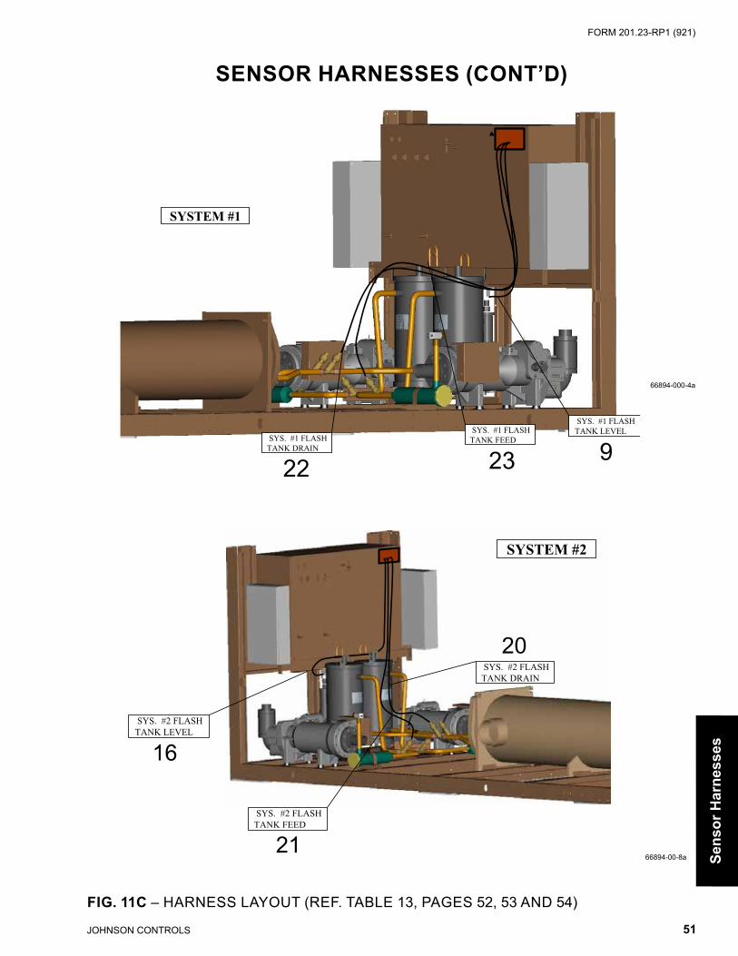
JOHNSON CONTROLS 51
FORM 201.23-RP1 (921)
66894-000-4a
SENSOR HARNESSES (CONT’D)
FIG. 11C – HARNESS LAYOUT (REF. TABLE 13, PAGES 52, 53 AND 54)
Sens
or H
arne
sses
66894-00-8a
SYSTEM #1
SYS. #1 FLASH TANK DRAIN
SYS. #1 FLASH TANK LEVEL SYS. #1 FLASH
TANK FEED
22 23 9
SYSTEM #2
SYS. #2 FLASH TANK LEVEL
SYS. #2 FLASH TANK DRAIN
SYS. #2 FLASH TANK FEED
21
16
20
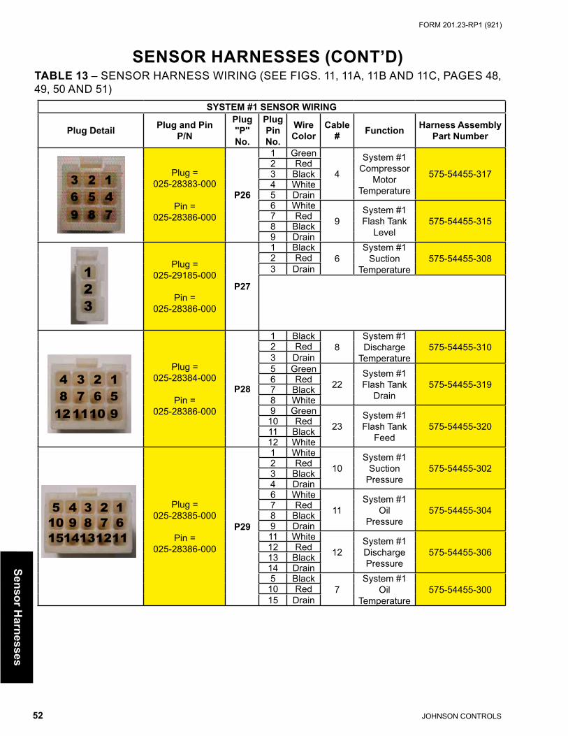
JOHNSON CONTROLS52
FORM 201.23-RP1 (921)
SENSOR HARNESSES (CONT’D)TABLE 13 – SENSOR HARNESS WIRING (SEE FIGS. 11, 11A, 11B AND 11C, PAGES 48, 49, 50 AND 51)
SYSTEM #1 SENSOR WIRING
Plug Detail Plug and PinP/N
Plug "P" No.
Plug Pin No.
Wire Color
Cable # Function Harness Assembly
Part Number
Plug = 025-28383-000
Pin =025-28386-000
P26
1 Green
4
System #1Compressor
MotorTemperature
575-54455-3172 Red3 Black4 White5 Drain6 White
9System #1Flash Tank
Level575-54455-3157 Red
8 Black9 Drain
Plug =025-29185-000
Pin =025-28386-000
P27
1 Black6
System #1Suction
Temperature575-54455-3082 Red
3 Drain
Plug =025-28384-000
Pin =025-28386-000
P28
1 Black8
System #1Discharge
Temperature575-54455-3102 Red
3 Drain5 Green
22System #1Flash Tank
Drain575-54455-3196 Red
7 Black8 White9 Green
23System #1Flash Tank
Feed575-54455-32010 Red
11 Black12 White
Plug =025-28385-000
Pin =025-28386-000
P29
1 White10
System #1Suction
Pressure575-54455-3022 Red
3 Black4 Drain6 White
11System #1
OilPressure
575-54455-3047 Red8 Black9 Drain11 White
12System #1DischargePressure
575-54455-30612 Red13 Black14 Drain5 Black
7System #1
OilTemperature
575-54455-30010 Red15 Drain
123
1234
91011125678
12345678910
1514131211Sensor H
arnesses

JOHNSON CONTROLS 53
FORM 201.23-RP1 (921)
TABLE 13 (CONT'D) – SENSOR HARNESS WIRING (SEE FIGS. 11, 11A, 11B AND 11C, PAGES 48, 49, 50 AND 51)
SYSTEM #2 SENSOR WIRING
Plug Detail Plug and Pin P/NPlug "P" No.
Plug Pin No.
Wire Color
Cable # Function Harness Assembly
Part Number
Plug =025-28383-001
Pin =025-28386-000
P30
1 Green
5
System #2Compressor
MotorTemperature
575-54455-3182 Red3 Black4 White5 Drain6 White
16System #2Flash Tank
Level575-54455-3167 Red
8 Black9 Drain
Plug =025-29185-001
Pin =025-28386-000
P31
1 Black13
System #2Suction
Temperature575-54455-3092 Red
3 Drain
Plug =025-28384-001
Pin =025-28386-000
P32
1 Black15
System #2Discharge
Temperature575-54455-3112 Red
3 Drain5 Green
20System #2Flash Tank
Drain575-54455-3216 Red
7 Black8 White9 Green
21System #2Flash Tank
Feed575-54455-32210 Red
11 Black12 White
Plug =025-28385-001
Pin =025-28386-000
P33
1 White17
System #2Suction
Pressure575-54455-3032 Red
3 Black4 Drain6 White
18System #2
OilPressure
575-54455-3057 Red8 Black9 Drain11 White
19System #2DischargePressure
575-54455-30712 Red13 Black14 Drain5 Black
14System #2
OilTemperature
575-54455-30110 Red15 Drain
123
1234
91011125678
12345678910
1514131211
SENSOR HARNESSES (CONT’D)
Sens
or H
arne
sses

JOHNSON CONTROLS54
FORM 201.23-RP1 (921)
TABLE 13 (CONT'D) – SENSOR HARNESS WIRING (SEE FIGS. 11, 11A, 11B AND 11C, PAGES 48, 49, 50 AND 51)
SENSOR HARNESSES (CONT’D)
UNIT SENSOR WIRING
Plug Detail Plug and Pin P/NPlug "P" No.
Plug Pin No.
Wire Color
Cable # Function Harness Assembly
Part Number
Plug =025-21192-000
Pin =025-19673-000
P25
1 Black1
LeavingWater
Temperature575-54455-3122 Red
3 Drain4 Black
2EnteringWater
Temperature575-54455-3135 Red
6 Drain7 Black
3Outside
AirTemperature
575-54455-3148 Red9 Drain
UNIT CONTROL WIRING
Plug Detail Plug and Pin P/NPlug "P" No.
Plug Pin No.
Wire Num-ber
Cable # Function Harness Assembly
Part Number
Plug =025-19671-000
Pin =025-20919-000
P36
1 224 Cooler
Heater 575-54455-2042 293 Ground
3 2 16 5 49 8 7
321
Sensor Harnesses

JOHNSON CONTROLS 55
FORM 201.23-RP1 (921)
Tran
sduc
ers,
Sen
sors
&
Con
nect
ors
TRANSDUCERS AND TEMP SENSORS
FIG. 12 – TRANSDUCERS AND TEMP SENSORS (REF. TABLE 14, PAGE 56)
66894-000-7
66894-000-2
LWT
EWT
23
23
1
SYSTEM #1
45
6
8

JOHNSON CONTROLS56
FORM 201.23-RP1 (921)
Transducers, Sensors &
Connectors
FIG. 12A – TRANSDUCERS AND HIGH PRESSURE CUT-OUT (REF. TABLE 14, PAGE 56)
s Recommended Spare Part
TRANSDUCERS AND TEMP SENSORS (CONT'D)
TABLE 14 – TRANSDUCERS, TEMP SENSORS AND HIGH PRESSURE CUT-OUT SWITCH (SEE FIGS. 12 AND 12A, PAGES 55 AND 56)
Item # Quantity Description
Volt-age
CodePart Number
1s 1 Sensor, Outside Air Temperature All 025-28663-0012s 2 Sensor, Water Temp. (EWT, LWT) All 025-40334-0003 - Compound, Heat Conductive All 013-00898-000
4s 2 per system Sensor, Discharge Temperature All 025-32924-0005s 2 per system Sensor, Suction Temperature All 025-28935-0006s 2 per system Sensor, Oil Temperature All 025-30440-0007s 1 per system Transducer, Oil Pressure (0-275psi) All 025-29139-0038s 1 per system Transducer, Discharge Pressure (0-275psi) All 025-29139-003
9As1 per system
Adapter, 3/4"-16M x 1/4 NPTF All 023-18225-0009Bs Valve, Transducer w/ 1/4" Flange All 022-09503-0009Cs Transducer, Suction Pressure (0-125psi) All 025-29583-00110A
1 per systemConnector, 7/16"-20M All 023-18087-000
10B High Pressure Cut Out Switch All 025-39956-00010C O-ring (Use with ITEM 10A) All 028-13540-00011A
1 per systemElbow, 90º Oil Inlet All 023-18945-000
11B O-ring (Use with ITEM 11A) All 028-12961-004
55658-000c
7
10A
9C
HIGH PRESSURE CUT-OUT
SUCTION PRESSURE
OIL PRESSURE
10B
10C
9B9A 11A
11B

JOHNSON CONTROLS 57
FORM 201.23-RP1 (921)
FIG. 13 – TRANSDUCER AND THERMISTOR WIRE HARNESS CONNECTORS - FIELDREPLACEMENT PART NUMBERS (REF. TABLE 15)
02492-2b
TABLE 15 – TRANSDUCER AND THERMISTOR WIRE HARNESS CONNECTORS - FIELD REPLACEMENT PART NUMBERS (SEE FIG. 13)
Item No. Location Description Pins Part Number
1Transducer
Plug Connector3 Pin End
025-28953-0002 Contact Pins 025-28949-0003 Rubber Collar 025-28950-0004
Wire HarnessPlug Connector
3 Pin End
025-28954-0005 Contact Pins 025-28952-0006 Rubber Collar 025-28950-0007
Temperature Sensor
Plug Connector2 Pin End
025-28948-0008 Contact Pins 025-28949-0009 Rubber Collar 025-28950-000
10Wire Harness
Plug Connector2 Pin End
025-28951-00011 Contact Pins 025-28952-00012 Rubber Collar 025-28950-000
s Recommended Spare Part
TRANSDUCER AND THERMISTORWIRE HARNESS CONNECTORS - FIELD
REPLACEMENT PART NUMBERS
Tran
sduc
ers,
Sen
sors
&
Con
nect
ors

JOHNSON CONTROLS58
FORM 201.23-RP1 (921)
VIBRATION ISOLATORSTABLE 16 – VIBRATION ISOLATORS PART NUMBERS
ONE INCH DEFLECTION SPRING ISOLATOR CROSS REFERENCEFOR UNITS WITH ALL POINT LOADS LESS THAN 1404 LBS. (637 KG.)
WEIGHT RANGE (lbs.)
WEIGHT RANGE (kg.)
VENDOR PART
NUMBERCOLOR YORK PART
NUMBER
239 to 384 lbs. 108 to 174 kg. CIP-B-450 RED 029-24583-002384 to 639 lbs. 174 to 290 kg. CIP-B-750 WHITE 029-24583-003639 to 851 lbs. 290 to 386 kg. CIP-B-1000 BLUE 029-24583-004
851 to 1064 lbs. 386 to 483 kg. CIP-B-1250 GRAY 029-24583-0051064 to 1404 lbs. 483 to 637 kg. CIP-B-1650 BLACK 029-24583-006
FOR UNITS WITH ANY POINT LOAD ABOVE 1404 LBS. (637 KG.)
WEIGHT RANGE (lbs.)
WEIGHT RANGE (kg.)
VENDOR PART
NUMBERCOLOR YORK PART
NUMBER
Up to 851 lbs. Up to 386 kg. CIP-B-1000 BLACK 029-24583-007851 to 1149 lbs. 386 to 521 kg. CIP-B-1350 YELLOW 029-24583-008
1149 to 1489 lbs. 521 to 675 kg. CIP-B-1750 BLACK 029-24583-0091489 to 1786 lbs. 675 to 910 kg. CIP-B-2100 YELLOW W/ RED 029-24583-0101786 to 2028 lbs. 910 to 920 kg. CIP-B-2385 YELLOW W/ GREEN 029-24583-0112028 to 2254 lbs. 920 to 1022 kg. CIP-B-2650 RED W/ RED 029-24583-0122254 to 2936 lbs. 1022 to 1332 kg. CIP-B-2935 RED W/ GREEN 029-24583-013
NEOPRENE ISOLATOR CROSS REFERENCE
WEIGHT RANGE (lbs.)
WEIGHT RANGE (kg.)
VENDOR PART
NUMBERCOLOR YORK PART
NUMBER
Up to 751 lbs. Up to 341 kg. ND-C YELLOW 029-24584-001751 to 1651 lbs. 341 to 749 kg. ND-D YELLOW 029-24584-002
1651 to 3226 lbs. 749 to 1463 kg. ND-DS YELLOW 029-24584-004
TWO INCH DEFLECTION, SEISMIC SPRING ISOLATOR CROSS REFERENCEWEIGHT
RANGE (lbs.)WEIGHT
RANGE (kg.)VENDOR PART
NUMBER COLOR YORK PARTNUMBER
Up to 358 lbs. Up to 162 kg. SLRS-2-C2-420 RED 029-24585-006358 to 443 lbs. 162 to 201 kg. SLRS-2-C2-520 WHITE 029-24585-007443 to 582 lbs. 201 to 264 kg. SLRS-2-C2-660 BLACK 029-24585-008582 to 783 lbs. 264 to 335 kg. SLRS-2-C2-920 BLUE 029-24585-009
783 to 1038 lbs. 335 to 471 kg. SLRS-2-C2-1220 GREEN 029-24585-0101038 to 1497 lbs. 471 to 679 kg. SLRS-2-C2-1760 GRAY 029-24585-0111497 to 2058 lbs. 679 to 933 kg. SLRS-2-C2-2420 SILVER 029-24585-0122058 to 2619 lbs. 933 to 1188 kg. SLRS-2-C2-3080 GRAY W/ RED 029-24585-0132619 to 3180 lbs. 1188 to 1442 kg. SLRS-2-C2-3740 SILVER W/ RED 029-24585-014
Chiller O
ptions

JOHNSON CONTROLS 59
FORM 201.23-RP1 (921)
TABLE 17 – FIELD INSTALLED OPTIONS PART NUMBERS
MODELNUMBER
YCIV
STANDARD150#
FLOWSWITCH
OPTIONAL300#
FLOWSWITCH
WELDFLANGE
KIT
VICTAULICFLANGE
KIT
DIFFERENTIALPRESSURE
SWITCH
MODEL # 024-26116 024-12144 023-02366 023- 025-309190590
-000 -000 -000
19201-000
-000
0600 19046-0000630
19201-000
06500700072007600770080008300840092009301000
Chi
ller O
ptio
ns
YCIV CHILLER OPTIONS
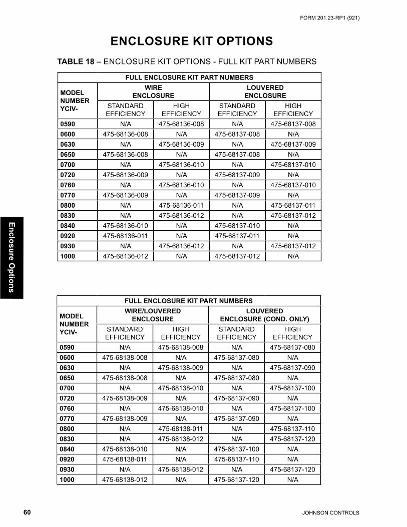
JOHNSON CONTROLS60
FORM 201.23-RP1 (921)
ENCLOSURE KIT OPTIONSTABLE 18 – ENCLOSURE KIT OPTIONS - FULL KIT PART NUMBERS
FULL ENCLOSURE KIT PART NUMBERS
MODELNUMBERYCIV-
WIREENCLOSURE
LOUVEREDENCLOSURE
STANDARDEFFICIENCY
HIGHEFFICIENCY
STANDARDEFFICIENCY
HIGHEFFICIENCY
0590 N/A 475-68136-008 N/A 475-68137-0080600 475-68136-008 N/A 475-68137-008 N/A0630 N/A 475-68136-009 N/A 475-68137-0090650 475-68136-008 N/A 475-68137-008 N/A0700 N/A 475-68136-010 N/A 475-68137-0100720 475-68136-009 N/A 475-68137-009 N/A0760 N/A 475-68136-010 N/A 475-68137-0100770 475-68136-009 N/A 475-68137-009 N/A0800 N/A 475-68136-011 N/A 475-68137-0110830 N/A 475-68136-012 N/A 475-68137-0120840 475-68136-010 N/A 475-68137-010 N/A0920 475-68136-011 N/A 475-68137-011 N/A0930 N/A 475-68136-012 N/A 475-68137-0121000 475-68136-012 N/A 475-68137-012 N/A
FULL ENCLOSURE KIT PART NUMBERS
MODELNUMBERYCIV-
WIRE/LOUVEREDENCLOSURE
LOUVEREDENCLOSURE (COND. ONLY)
STANDARDEFFICIENCY
HIGHEFFICIENCY
STANDARDEFFICIENCY
HIGHEFFICIENCY
0590 N/A 475-68138-008 N/A 475-68137-0800600 475-68138-008 N/A 475-68137-080 N/A0630 N/A 475-68138-009 N/A 475-68137-0900650 475-68138-008 N/A 475-68137-080 N/A0700 N/A 475-68138-010 N/A 475-68137-1000720 475-68138-009 N/A 475-68137-090 N/A0760 N/A 475-68138-010 N/A 475-68137-1000770 475-68138-009 N/A 475-68137-090 N/A0800 N/A 475-68138-011 N/A 475-68137-1100830 N/A 475-68138-012 N/A 475-68137-1200840 475-68138-010 N/A 475-68137-100 N/A0920 475-68138-011 N/A 475-68137-110 N/A0930 N/A 475-68138-012 N/A 475-68137-1201000 475-68138-012 N/A 475-68137-120 N/A
Enclosure Options

JOHNSON CONTROLS 61
FORM 201.23-RP1 (921)
FULL KIT NUMBER TOP OR BOTTOM PART NUMBERWIRE ENCLOSURES
475-68136-008 (Top) 375-68136-080(Bottom) 375-68136-081
475-68136-009 (Top) 375-68136-090(Bottom) 375-68136-101
475-68136-010 (Top) 375-68136-100(Bottom) 375-68136-101
475-68136-011 (Top) 375-68136-110(Bottom) 375-68136-121
475-68136-012 (Top) 375-68136-120(Bottom) 375-68136-121
LOUVERED ENCLOSURE
475-68137-008 (Top) 375-68137-080(Bottom) 375-68137-081
475-68137-009 (Top) 375-68137-090(Bottom) 375-68137-101
475-68137-010 (Top) 375-68137-100(Bottom) 375-68137-101
475-68137-011 (Top) 375-68137-110(Bottom) 375-68137-121
475-68137-012 (Top) 375-68137-120(Bottom) 375-68137-121
WIRE/LOUVERED ENCLOSURE
475-68138-008 (Top) 375-68138-080(Bottom) 375-68138-081
475-68138-009 (Top) 375-68138-090(Bottom) 375-68138-101
475-68138-010 (Top) 375-68138-100(Bottom) 375-68138-101
475-68138-011 (Top) 375-68138-110(Bottom) 375-68138-121
475-68138-012 (Top) 375-68138-120(Bottom) 375-68138-121
ENCLOSURE KIT OPTIONS (CONT’D)TABLE 18A – ENCLOSURE KIT OPTIONS - TOP AND BOTTOM SECTIONS (SEE FIGS. 14, 15, 16, 17 AND 17A, PAGES 62-66)
Encl
osur
e O
ptio
ns

JOHNSON CONTROLS62
FORM 201.23-RP1 (921)
ENCLOSURE KIT OPTIONS (CONT’D)
TABLE 19 – WIRE ENCLOSURE (TOP SECTIONS) - (SEE FIG. 14)
FIG. 14 – WIRE ENCLOSURE (TOP SECTIONS) - 475-68136-008 SHOWN (REF. TABLE 19)
** Refer to page 49, Quanity for 375-68136-009 = 9** Refer to page 49, Quanity for 375-68136-010 = 10** Refer to page 49, Quanity for 375-68136-011 = 11** Refer to page 49, Quanity for 375-68136-012 = 12
Enclosure Options
WIRE ENCLOSURE TOP SECTIONS KIT COMPONENTSITEM
# DESCRIPTION PARTNUMBER QTY
100 END PANEL - LH 075-57085-000 1101 END PANEL - RH 075-57086-000 1103 CHANNEL 075-57082-000 1104 PLATE 075-57133-000 1105 PANEL - SIDE 075-66961-000 1200 WIRE GRILL CONDENSER 026-41776-000 8**
200
200
105OR
USE ITEM 105 ONUNITS WITH AN ODDNUMBER OF FANS.
103104
100
101
200
68136-000

JOHNSON CONTROLS 63
FORM 201.23-RP1 (921)
68136-001A
ENCLOSURE KIT OPTIONS (CONT’D)
TABLE 20 – WIRE ENCLOSURE (BOTTOM SECTIONS) - (SEE FIG. 15)
FIG. 15 – WIRE ENCLOSURE (BOTTOM SECTIONS) - 375-68136-081 SHOWN (REF. TABLE 20)
WIRE ENCLOSURE BOTTOM SECTIONS KIT COMPONENTSITEM
# DESCRIPTION PARTNUMBER QTY
100 REAR SUPPORT 075-68135-000 1200 WIRE GRILL 026-44013-000 6**201 WIRE GRILL - REAR 026-44014-000 2202 WIRE GRILL 026-44017-000 2203 WIRE GRILL 026-44016-000 2204 WIRE GRILL 026-44015-000 2205 WIRE GRILL - FRONT 026-44018-000 2
** Refer to page 49, Quanity for 375-68136-101 = 8** Refer to page 49, Quanity for 375-68136-201 = 10
Encl
osur
e O
ptio
ns
202
205
203
204200 201
100

JOHNSON CONTROLS64
FORM 201.23-RP1 (921)
TABLE 21 – LOUVERED ENCLOSURE (TOP SECTIONS) - (SEE FIG. 16)
ENCLOSURE KIT OPTIONS (CONT’D)
FIG. 16 – LOUVERED ENCLOSURE (TOP SECTIONS) - 375-68137-080 SHOWN (REF. TABLE 21)
68137-000
LOUVERED ENCLOSURE TOP SECTIONS KIT COMPONENTSITEM
# DESCRIPTION PART NUMBER QTY
100 LOUVER PANEL 075-56976-000 8**101 REAR PANEL - LH 075-57085-000 1102 REAR PANEL - RH 075-57086-000 1103 CHANNEL 075-57082-000 1104 REAR SUPPORT 075-57133-000 1106 LOUVERED PANEL - SIDE 075-66961-000 1
** Refer to page 49, Quanity for 375-68137-090 = 9** Refer to page 49, Quanity for 375-68137-100 = 10** Refer to page 49, Quanity for 375-68137-110 = 11** Refer to page 49, Quanity for 375-68137-120 = 12
Enclosure Options
100100
106OR
USE ITEM 106 ONUNITS WITH AN ODDNUMBER OF FANS.
103104
101
102
100

JOHNSON CONTROLS 65
FORM 201.23-RP1 (921)
108
107 106105 103
100105
104
100100
100106
101
102
NOTE:RIGHT HAND WATER CONNECTION
ENCLOSURE KIT OPTIONS (CONT’D)
Encl
osur
e O
ptio
ns
TABLE 22 – LOUVERED ENCLOSURE (BOTTOM SECTIONS)(SEE FIGS. 17 and 17A, PAGES 65 AND 66)
FIG. 17 – LOUVERED ENCLOSURE (BOTTOM SECTIONS)375-68137-081 SHOWN (REF. TABLE 22)
LOUVERED ENCLOSURE BOTTOM SECTIONS KIT COMPONENTSITEM
# DESCRIPTION PART NUMBER QTY
100 LOUVER PANEL 075-68132-000 4**101 LOUVER PANEL 075-68133-000 2102 SUPPORT 075-68135-000 1103 LOUVER PANEL 075-68139-000 1104 LOUVER PANEL 075-68140-000 1105 COVER PANEL 075-57112-000 2106 LOUVER PANEL 075-68131-000 2107 PANEL - SIDE 075-66949-000 2108 PANEL - SIDE 075-65694-000 2109 PANEL - FRONT 075-65693-000 1110 PANEL - FRONT 075-65691-000 1111 COVER PANEL 075-65692-000 1
** Refer to page 49, Quanity for 375-68137-101 = 6** Refer to page 49, Quanity for 375-68137-121 = 8
68137-001a

JOHNSON CONTROLS66
FORM 201.23-RP1 (921)
ENCLOSURE KIT OPTIONS (CONT’D)
Enclosure Options
FIG. 17A – LOUVERED ENCLOSURE (BOTTOM SECTIONS)375-68137-081 SHOWN (REF. TABLE 22, PAGE 65)
100�100�
100�
101
107108
108107
110
111
109
10668137-001ba

JOHNSON CONTROLS 67
FORM 201.23-RP1 (921)
RECOMMENDED SPARE PARTSYork Model YCIV Style A Air Cooled Screw Chillers
Suggested Spare Parts List for Critical Duty Applications
All parts must be purchased from your local YORK Sales and Service Center.
TABLE 23 – RECOMMENDED SPARE PARTS - YCIV0590-YCIV1000 CHILLERS
PAGE REF. &ITEM NUMBER DESCRIPTION
MODEL NUMBER
YCIV
PARTNUMBER
Page 12, Item 1 Fan Motor (Ultra Quiet)-40 024-27322-004-46 024-27322-007-50 024-27322-005
Page 12, Item 1 Fan Motor (High Static)-40 024-34980-005-46 024-34980-001-50 024-34980-003
Page 12, Item 2Fan Blade (Ultra Quiet) All 026-41594-000Fan Blade (High Static) All 026-41942-000
Pages 15, 16 and 17, Item 1 Valve, Control (Feed or Drain) See Table 4
025-41564-000025-41565-000
Page 15, 16 and 17, Item 5 Core, Dehydrator All 026-37540-000
Page 15, 16 and 17, Item 20 Sensor, Refrig Level All 025-40274-000
Page 19, Item 10 Cap, Radiator All 023-21927-000
Page 19, Item 13Coolant PG (5 gallon), non EU compliant
All013-03344-000
Coolant PG (5 gallon), EU compliant* 013-03849-001Page 26, Item OIL Oil, Compressor (Type 'L') R-134A 011-00592-000Page 31, Item 28B Chiller Control Board See Table 8 331-03478-6xx
Page 31, Item 72Controller, Drain/Feed (90º Flow)
See Table 8 031-02510-000
Controller, Drain/Feed (Straight Flow) 031-02742-000Page 32-39, Item 190 VSD Logic Board All 031-02477-000Page 32-39, Item 190a VSD Logic Board All 031-02507-000Page 56, Item 1 Sensor, Outside Air Temperature All 025-28663-001Page 56, Item 2 Sensor, Water Temp. (EWT, LWT) All 025-40334-000Page 56, Item 4 Sensor, Discharge Temperature All 025-32924-000Page 56, Item 5 Sensor, Suction Temperature All 025-28935-000Page 56, Item 6 Sensor, Oil Temperature All 025-30440-000Page 56, Item 7 and 8 Transducer, Discharge & Oil Pressure (0-275psi) All 025-29139-003Page 56, Item 9 Transducer, Suction Pressure (0-125psi) All 025-29583-001
Spar
e Pa
rts

5000 Renaissance Drive, New Freedom, Pennsylvania USA 17349 1-800-524-1330 Subject to change without notice. Printed in USACopyright © by Johnson Controls 2021 www.johnsoncontrols.com ALL RIGHTS RESERVEDForm 201.23-RP1 (921)Issue Date: September 30, 2021 Supersedes: 201.23-RP1 (918)