Yasuhiro Fukuoka Adaptive Dynamic Hiroshi Kimura Walking of … · Yasuhiro Fukuoka Hiroshi Kimura...
16
Yasuhiro Fukuoka Hiroshi Kimura Graduate School of Information Systems University of Electro-Communications Chofu, Tokyo 182-8585, Japan [email protected] [email protected] Avis H. Cohen Department of Biology and Institute for Systems Research Univ. of Maryland College Park, MD 20742, USA [email protected] Adaptive Dynamic Walking of a Quadruped Robot on Irregular Terrain Based on Biological Concepts Abstract We have been trying to induce a quadruped robot to walk with medium walking speed on irregular terrain based on biological con- cepts. We propose the necessary conditions for stable dynamic walk- ing on irregular terrain in general, and we design the mechanical system and the neural system by comparing biological concepts with those necessary conditions described in physical terms. A PD con- troller at the joints can construct the virtual spring–damper system as the visco-elasticity model of a muscle. The neural system model consists of a central pattern generator (CPG) and reflexes. A CPG re- ceives sensory input and changes the period of its own active phase. The desired angle and P-gain of each joint in the virtual spring– damper system is switched based on the phase signal of the CPG. CPGs, the motion of the virtual spring–damper system of each leg and the rolling motion of the body are mutually entrained through the rolling motion feedback to CPGs, and can generate adaptive walking. We report on our experimental results of dynamic walking on terrains of medium degrees of irregularity in order to verify the effectiveness of the designed neuro-mechanical system. We point out the trade-off problem between the stability and the energy consump- tion in determining the cyclic period of walking on irregular terrain, and we show one example to solve this problem. MPEG footage of these experiments can be seen at http://www.kimura.is.uec.ac.jp. KEY WORDS—AUTHOR: PLEASE PROVIDE The International Journal of Robotics Research Vol. 22, No. 2, February 2003, pp. xxx-xxx, ©2003 Sage Publications 1. Introduction Many previous studies of legged robots have been performed, including studies on running (Hodgins and Raibert 1991) and dynamic walking (Yamaguchi, Takanishi, and Kato 1994; Ka- jita and Tani 1996; Chew, Pratt, and Pratt 1999; Yoneda, Iiyama, and Hirose 1994; Buehler et al. 1998) on irregular terrain. However, studies of autonomous dynamic adaptation allowing a robot to cope with an infinite variety of terrain irregularities have been started only recently and by only a few research groups. One example is the recent achievement of high-speed mobility of a hexapod over irregular terrain, with appropriate mechanical compliance of the legs (Saranli, Buehler, and Koditschek 2001; Cham et al. 2001). The pur- pose of this study is to realize high-speed mobility on irreg- ular terrain using a mammal-like quadruped robot, the dy- namic walking of which is less stable than that of hexapod robots, by referring to the marvelous abilities of animals to autonomously adapt to their environment. As many biological studies of motion control have pro- gressed, it has become generally accepted that the walking of animals is mainly generated at the spinal cord by a com- bination of a central pattern generator (CPG) and reflexes receiving adjustment signals from a cerebrum, cerebellum and brain stem (Grillner 1981; Cohen and Boothe 1999). A great deal of the previous research on this attempted to gen- erate walking using a neural system model, including studies on dynamic walking in simulation (Taga, Yamaguchi, and Shimizu 1991; Taga 1995; Miyakoshi et al. 1998; Ijspeert 2001), and real robots (Kimura, Akiyama, and Sakurama 1999; Ilg et al. 1999; Tsujita, Tsuchiya, and Onat 2001; Lewis et al. 2003). But autonomously adaptable dynamic walking on 1
Transcript of Yasuhiro Fukuoka Adaptive Dynamic Hiroshi Kimura Walking of … · Yasuhiro Fukuoka Hiroshi Kimura...
Yasuhiro FukuokaHiroshi KimuraGraduate School of Information SystemsUniversity of Electro-CommunicationsChofu, Tokyo 182-8585, [email protected]@kimura.is.uec.ac.jp
Avis H. CohenDepartment of Biology and Institutefor Systems ResearchUniv. of MarylandCollege Park, MD 20742, [email protected]
Adaptive DynamicWalking of aQuadruped Roboton Irregular TerrainBased on BiologicalConcepts
Abstract
We have been trying to induce a quadruped robot to walk withmedium walking speed on irregular terrain based on biological con-cepts. We propose the necessary conditions for stable dynamic walk-ing on irregular terrain in general, and we design the mechanicalsystem and the neural system by comparing biological concepts withthose necessary conditions described in physical terms. A PD con-troller at the joints can construct the virtual spring–damper systemas the visco-elasticity model of a muscle. The neural system modelconsists of a central pattern generator (CPG) and reflexes. A CPG re-ceives sensory input and changes the period of its own active phase.The desired angle and P-gain of each joint in the virtual spring–damper system is switched based on the phase signal of the CPG.CPGs, the motion of the virtual spring–damper system of each legand the rolling motion of the body are mutually entrained throughthe rolling motion feedback to CPGs, and can generate adaptivewalking. We report on our experimental results of dynamic walkingon terrains of medium degrees of irregularity in order to verify theeffectiveness of the designed neuro-mechanical system. We point outthe trade-off problem between the stability and the energy consump-tion in determining the cyclic period of walking on irregular terrain,and we show one example to solve this problem. MPEG footage ofthese experiments can be seen at http://www.kimura.is.uec.ac.jp.
KEY WORDS—AUTHOR: PLEASE PROVIDE
The International Journal of Robotics ResearchVol. 22, No. 2, February 2003, pp. xxx-xxx,©2003 Sage Publications
1. Introduction
Many previous studies of legged robots have been performed,including studies on running (Hodgins and Raibert 1991) anddynamic walking (Yamaguchi, Takanishi, and Kato 1994; Ka-jita and Tani 1996; Chew, Pratt, and Pratt 1999; Yoneda,Iiyama, and Hirose 1994; Buehler et al. 1998) on irregularterrain. However, studies of autonomous dynamic adaptationallowing a robot to cope with an infinite variety of terrainirregularities have been started only recently and by only afew research groups. One example is the recent achievementof high-speed mobility of a hexapod over irregular terrain,with appropriate mechanical compliance of the legs (Saranli,Buehler, and Koditschek 2001; Cham et al. 2001). The pur-pose of this study is to realize high-speed mobility on irreg-ular terrain using a mammal-like quadruped robot, the dy-namic walking of which is less stable than that of hexapodrobots, by referring to the marvelous abilities of animals toautonomously adapt to their environment.
As many biological studies of motion control have pro-gressed, it has become generally accepted that the walkingof animals is mainly generated at the spinal cord by a com-bination of a central pattern generator (CPG) and reflexesreceiving adjustment signals from a cerebrum, cerebellumand brain stem (Grillner 1981; Cohen and Boothe 1999). Agreat deal of the previous research on this attempted to gen-erate walking using a neural system model, including studieson dynamic walking in simulation (Taga, Yamaguchi, andShimizu 1991; Taga 1995; Miyakoshi et al. 1998; Ijspeert2001), and real robots (Kimura, Akiyama, and Sakurama1999; Ilg et al. 1999; Tsujita, Tsuchiya, and Onat 2001; Lewiset al. 2003). But autonomously adaptable dynamic walking on
1

2 THE INTERNATIONAL JOURNAL OF ROBOTICS RESEARCH / February 2003
irregular terrain was rarely realized in those earlier studies. Inthis paper we report on our progress in the past couple ofyears using a newly developed quadruped called “Tekken”,which contains a mechanism designed for three-dimensional(3D) space walking (pitch, roll and yaw planes) on irregularterrain.
In this paper we would like to emphasize three key con-cepts: (1) the necessary conditions for stable dynamic walkingon irregular terrain and the neural system model contributingto satisfy those conditions described in Sections 2.4 and 2.5;(2) the entrainment between pitching motion of legs, rollingmotion of the body and CPGs described in Section 3; (3) thecoupled-dynamics-based motion generation for autonomousadaptation described in Section 6.1. These key concepts arecommon to both animals and machines in spite of the differ-ences in their mechanisms, actuators, sensors and so on.
2. Adaptive Dynamic Walking based onBiological Concepts
Methods for legged locomotion control are classified into zeromoment point (ZMP) based control and limit-cycle-basedcontrol (Table 1). ZMP is the extension of the center of grav-ity considering inertia force and so on. It was shown thatZMP-based control is effective for controlling posture andlow-speed walking of a biped (Takanishi et al. 1990) anda quadruped (Yoneda, Iiyama, and Hirose 1994). However,ZMP-based control is not good for medium- or high-speedwalking from the standpoint of energy consumption, since abody with a large mass needs to be accelerated and deceleratedby actuators in every step cycle.
In contrast, motion generated by the limit-cycle-based con-trol has superior energy efficiency. But there is an upper boundof the period of the walking cycle, in which stable dynamicwalking can be realized (Kimura, Shimoyama, and Miura1990). It should be noted that control by a neural system con-sisting of CPGs and reflexes is dominant for various kindsof adjustments in medium-speed walking of animals (Grill-ner 1981). Full and Koditschek (1999) also pointed out that,in high-speed running, kinetic energy is dominant, and self-stabilization by a mechanism with a spring and a damper ismore important than adjustments by the neural system. Ourstudy is aimed at medium-speed walking controlled by CPGsand reflexes (Table 1).
In this paper, we define a “reflex” as joint torque generationbased on sensor information and a “response” as CPG phasemodulation through sensory feedback to a CPG.
2.1. The Quadruped “Tekken”
We designed Tekken (Figure 1(a)) to solve the mechanicalproblems which occurred in our past study using a planarquadruped “Patrush” (Kimura, Fukuoka et al. 2001). The
pitchroll
yaw
A
B rubber band
ζurethane gel
(a) (b)Fig. 1. A quadruped robot, Tekken: (a) photograph, (b)passive ankle joint.
lengths of the body and a leg in standing are 23 and 20 cm, re-spectively. The weights of the whole robot, a whole leg and alower link under a knee are 3.1, 0.5 and 0.06 kg, respectively.Each leg has a hip pitch joint, a hip yaw joint, a knee pitchjoint, and an ankle pitch joint. The hip pitch joint, knee pitchjoint and hip yaw joint are activated by dc motors of 20, 20and 5 W through gear ratios of 15.6, 18.8 and 84, respectively.
The ankle joint can be passively rotated in the directionshown by A in Figure 1(b) if the toe contacts with an obstaclein a swing phase, and is locked while the leg is in a stancephase. This passive mechanism quickly prevents a swingingleg from stumbling on an obstacle. In Figure 1(b), since theurethane gel inserted between two links is crushed elasticallyin a stance phase, we can detect the contact of a leg with thefloor by the potentiometer at the ankle joint. As a result, wecan detect three states of a leg by the ankle joint angle, ζ :stance (ζ < 3◦), swinging in the air (ζ � 10◦) and stumblingon an obstacle (ζ > 20◦).
Two rate gyro sensors and two inclinometers for pitch androll axes are mounted on the body in order to measure thebody pitch and roll angles. The direction in which Tekkenmoves while walking can be changed by using the hip yawjoints.
2.2. Rhythmic Motion by CPG
Although actual neurons as a CPG in higher animals havenot yet become well known, features of a CPG have beenactively studied in biology, physiology, and so on. Severalmathematical models have also been proposed, and it has beenpointed out that a CPG has the capability to generate andmodulate walking patterns and to be mutually entrained witha rhythmic joint motion (Grillner 1981; Cohen and Boothe1999; Taga, Yamaguchi, and Shimizu 1991; Taga 1995). As amodel of a CPG, we used a neural oscillator (NO) proposed byMatsuoka (1987), and applied to the biped simulation by Taga,Yamaguchi, and Shimizu (1991) and Taga (1995). A singleNO consists of two mutually inhibiting neurons (Figure 2).Each neuron in this model is represented by the followingnonlinear differential equations:
Fukuoka, Kimura, and Cohen / Adaptive Dynamic Walking of A Quadruped Robot 3
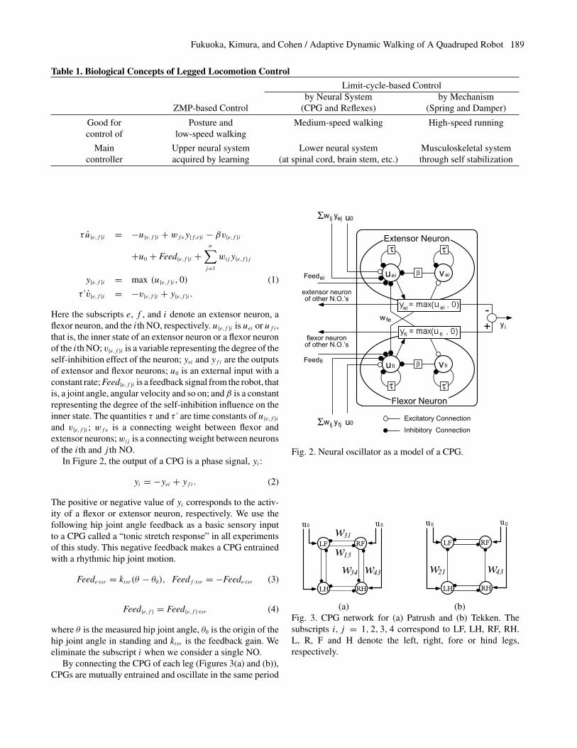
Table 1. Biological Concepts of Legged Locomotion Control
Limit-cycle-based Controlby Neural System by Mechanism
ZMP-based Control (CPG and Reflexes) (Spring and Damper)
Good for Posture and Medium-speed walking High-speed runningcontrol of low-speed walking
Main Upper neural system Lower neural system Musculoskeletal systemcontroller acquired by learning (at spinal cord, brain stem, etc.) through self stabilization
τ u̇{e,f }i = −u{e,f }i + wfey{f,e}i − βv{e,f }i
+u0 + Feed{e,f }i +n∑j=1
wijy{e,f }j
y{e,f }i = max (u{e,f }i , 0) (1)
τ ′v̇{e,f }i = −v{e,f }i + y{e,f }i .
Here the subscripts e, f , and i denote an extensor neuron, aflexor neuron, and the ith NO, respectively. u{e,f }i is uei or uf i ,that is, the inner state of an extensor neuron or a flexor neuronof the ith NO; v{e,f }i is a variable representing the degree of theself-inhibition effect of the neuron; yei and yf i are the outputsof extensor and flexor neurons; u0 is an external input with aconstant rate; Feed{e,f }i is a feedback signal from the robot, thatis, a joint angle, angular velocity and so on; and β is a constantrepresenting the degree of the self-inhibition influence on theinner state. The quantities τ and τ ′ are time constants of u{e,f }iand v{e,f }i ; wfe is a connecting weight between flexor andextensor neurons;wij is a connecting weight between neuronsof the ith and j th NO.
In Figure 2, the output of a CPG is a phase signal, yi :
yi = −yei + yf i . (2)
The positive or negative value of yi corresponds to the activ-ity of a flexor or extensor neuron, respectively. We use thefollowing hip joint angle feedback as a basic sensory inputto a CPG called a “tonic stretch response” in all experimentsof this study. This negative feedback makes a CPG entrainedwith a rhythmic hip joint motion.
Feede·tsr = ktsr (θ − θ0), Feedf ·tsr = −Feede·tsr (3)
Feed{e,f } = Feed{e,f }·tsr (4)
where θ is the measured hip joint angle, θ0 is the origin of thehip joint angle in standing and ktsr is the feedback gain. Weeliminate the subscript i when we consider a single NO.
By connecting the CPG of each leg (Figures 3(a) and (b)),CPGs are mutually entrained and oscillate in the same period
Feedei uei
ufi
vei
v fi
Σ yejwij
Feedfi
Σ yfjwij
yi+-ei ei
β
,
β
Excitatory Connection
Inhibitory Connectionu0
u0
Extensor Neuron
Flexor Neuron
wfe
fi fi
ττ
,ττ
extensor neuronof other N.O.’s
flexor neuronof other N.O.’s
Fig. 2. Neural oscillator as a model of a CPG.
w31
w13
w34 w43 w43w21
(a) (b)Fig. 3. CPG network for (a) Patrush and (b) Tekken. Thesubscripts i, j = 1, 2, 3, 4 correspond to LF, LH, RF, RH.L, R, F and H denote the left, right, fore or hind legs,respectively.
4 THE INTERNATIONAL JOURNAL OF ROBOTICS RESEARCH / February 2003
and with a fixed phase difference. This mutual entrainmentbetween the CPGs of the legs results in a gait. The gait isa walking pattern, and can be defined by phase differences(0 ∼ 1) between the legs during their pitching motion. Whenwe use γ for the phase difference from the left hind leg to theleft fore leg, the typical symmetric gaits are a trot (γ � 0.5)and a pace (γ � 0). Diagonal legs and lateral legs are pairedand move together in a trot gait and a pace gait, respectively.A walk gait is the transversal gait between the trot and pacegaits (Table 2).
Since there is not much meaning in a gait of planar walking,the gait of Patrush was fixed to a trot gait using the symmetricCPG network (Figure 3(a)). However, since a gait is one ofthe important subjects in 3D walking using Tekken, we newlypropose an asymmetric CPG network shown in Figure 3(b)in order to generate an arbitrary gait from a trot to a pacevia a walk with a single network configuration of CPGs. InFigure 3(b), a CPG of a fore leg is inhibited by a CPG of ahind leg with a connecting weight, w{21,43}, and a CPG of ahind leg is not inhibited by a CPG of a fore leg (w{12,34}=0).
2.3. Virtual Spring–Damper System
Muscles and tendons of animals act as a spring–damper sys-tem in medium- and high-speed walking and running, andplay an important role for stabilization and energy storage.The whole visco-elasticity of a muscle is the sum of its ownvisco-elasticity as a material and the visco-elasticity as a re-sult of feedback by the stretch reflex and others. It is alsoknown that the muscle stiffness in the stretch reflex is almostproportional to the muscle tension, high in a stance phase forsupporting a body against gravity and low in a swing phase forcompliance against the disturbance, during the walking of cats(Akazawa et al. 1982). Full and Koditschek (1999) and Full(2000) pointed out the importance of the mechanical visco-elasticity of muscles and tendons independent of sensory inputunder the concepts of the “Spring Loaded Inverted Pendulum”(“SLIP”) and the “preflex”. These biological concepts wereapplied for the development of hexapods with high-speed mo-bility over irregular terrain (Saranli, Buehler, and Koditschek2001; Cham et al. 2001). Although we refer to the conceptof SLIP, we employ the model of the muscle stiffness, whichis generated by the stretch reflex and variable according tothe stance/swing phases, aiming at medium-speed walkingon irregular terrain adjusted by the neural system.
All joints of Tekken are PD controlled to move to their
Table 2. Definition of Gaitsγ Gait
−0.025 ≤ < 0.125 Pace0.125 ≤ < 0.375 Walk0.375 ≤ < 0.525 Trot
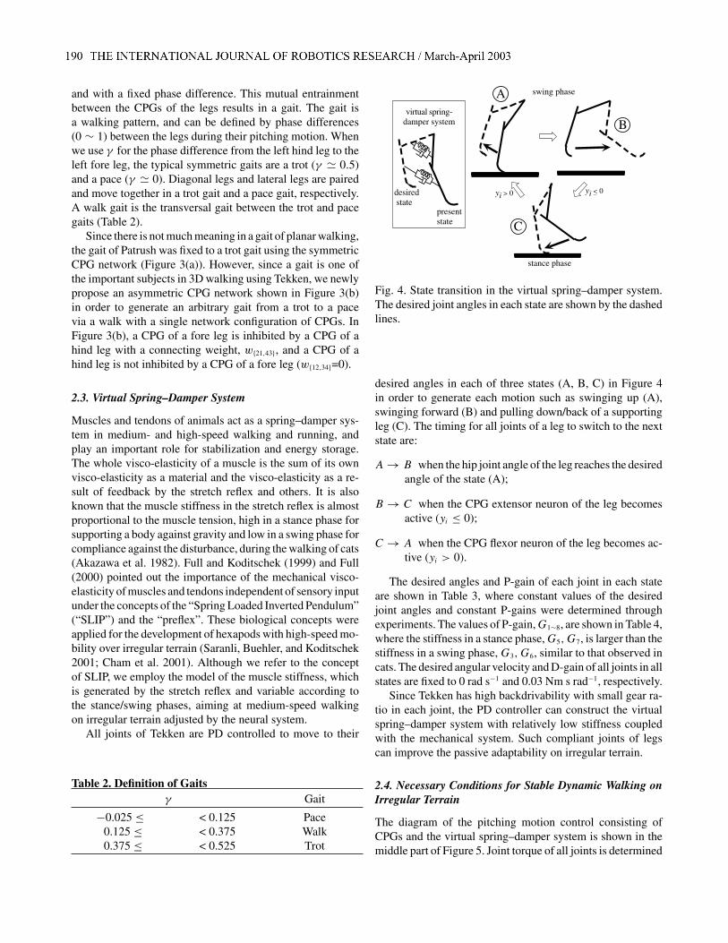
A
yi < 0yi > 0desired state
presentstate
virtual spring-damper system
swing phase
stance phase
B
C
Fig. 4. State transition in the virtual spring–damper system.The desired joint angles in each state are shown by the dashedlines.
desired angles in each of three states (A, B, C) in Figure 4in order to generate each motion such as swinging up (A),swinging forward (B) and pulling down/back of a supportingleg (C). The timing for all joints of a leg to switch to the nextstate are:
A → B when the hip joint angle of the leg reaches the desiredangle of the state (A);
B → C when the CPG extensor neuron of the leg becomesactive (yi ≤ 0);
C → A when the CPG flexor neuron of the leg becomes ac-tive (yi > 0).
The desired angles and P-gain of each joint in each stateare shown in Table 3, where constant values of the desiredjoint angles and constant P-gains were determined throughexperiments. The values of P-gain,G1∼8, are shown in Table 4,where the stiffness in a stance phase,G5,G7, is larger than thestiffness in a swing phase,G3,G6, similar to that observed incats. The desired angular velocity and D-gain of all joints in allstates are fixed to 0 rad s−1 and 0.03 Nm s rad−1, respectively.
Since Tekken has high backdrivability with small gear ra-tio in each joint, the PD controller can construct the virtualspring–damper system with relatively low stiffness coupledwith the mechanical system. Such compliant joints of legscan improve the passive adaptability on irregular terrain.
2.4. Necessary Conditions for Stable Dynamic Walking onIrregular Terrain
The diagram of the pitching motion control consisting ofCPGs and the virtual spring–damper system is shown in themiddle part of Figure 5. Joint torque of all joints is determined
Fukuoka, Kimura, and Cohen / Adaptive Dynamic Walking of A Quadruped Robot 5
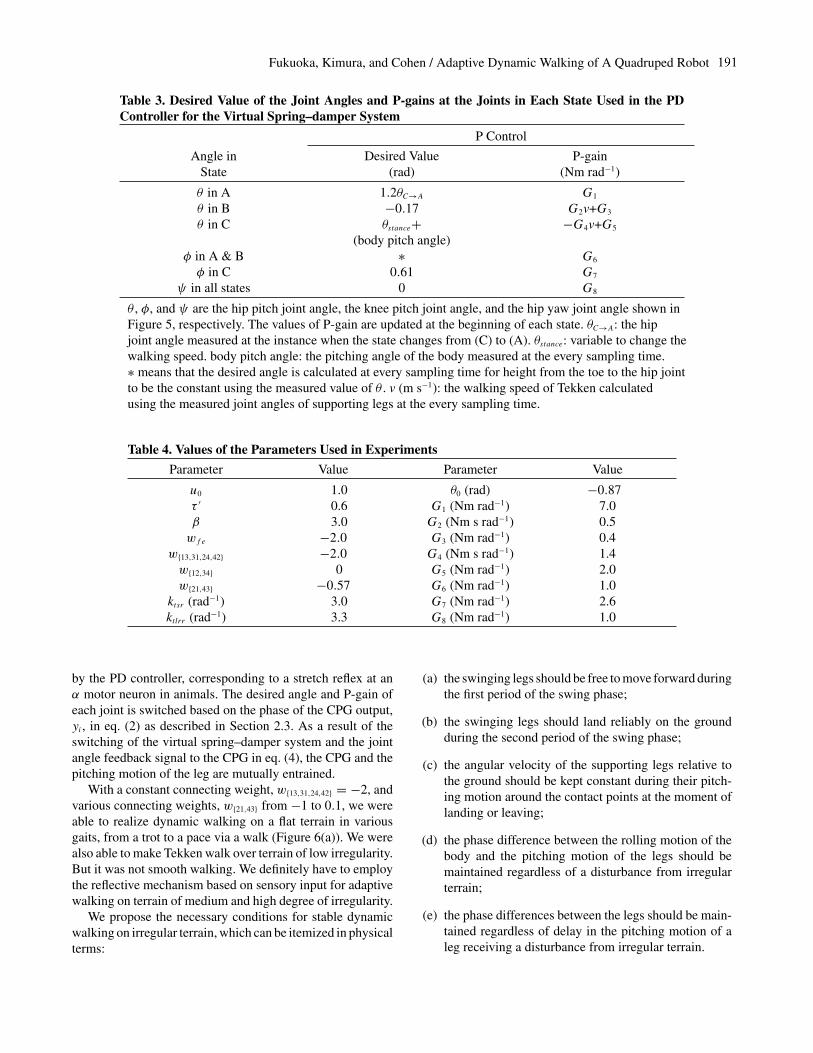
Table 3. Desired Value of the Joint Angles and P-gains at the Joints in Each State Used in the PDController for the Virtual Spring–damper System
P Control
Angle in Desired Value P-gainState (rad) (Nm rad−1)
θ in A 1.2θC→A G1
θ in B −0.17 G2v+G3
θ in C θstance+ −G4v+G5
(body pitch angle)φ in A & B ∗ G6
φ in C 0.61 G7
ψ in all states 0 G8
θ , φ, and ψ are the hip pitch joint angle, the knee pitch joint angle, and the hip yaw joint angle shown inFigure 5, respectively. The values of P-gain are updated at the beginning of each state. θC→A: the hipjoint angle measured at the instance when the state changes from (C) to (A). θstance: variable to change thewalking speed. body pitch angle: the pitching angle of the body measured at the every sampling time.∗ means that the desired angle is calculated at every sampling time for height from the toe to the hip jointto be the constant using the measured value of θ . v (m s−1): the walking speed of Tekken calculatedusing the measured joint angles of supporting legs at the every sampling time.
Table 4. Values of the Parameters Used in Experiments
Parameter Value Parameter Value
u0 1.0 θ0 (rad) −0.87τ ′ 0.6 G1 (Nm rad−1) 7.0β 3.0 G2 (Nm s rad−1) 0.5wfe −2.0 G3 (Nm rad−1) 0.4
w{13,31,24,42} −2.0 G4 (Nm s rad−1) 1.4w{12,34} 0 G5 (Nm rad−1) 2.0w{21,43} −0.57 G6 (Nm rad−1) 1.0
ktsr (rad−1) 3.0 G7 (Nm rad−1) 2.6ktlrr (rad−1) 3.3 G8 (Nm rad−1) 1.0
by the PD controller, corresponding to a stretch reflex at anα motor neuron in animals. The desired angle and P-gain ofeach joint is switched based on the phase of the CPG output,yi , in eq. (2) as described in Section 2.3. As a result of theswitching of the virtual spring–damper system and the jointangle feedback signal to the CPG in eq. (4), the CPG and thepitching motion of the leg are mutually entrained.
With a constant connecting weight, w{13,31,24,42} = −2, andvarious connecting weights, w{21,43} from −1 to 0.1, we wereable to realize dynamic walking on a flat terrain in variousgaits, from a trot to a pace via a walk (Figure 6(a)). We werealso able to make Tekken walk over terrain of low irregularity.But it was not smooth walking. We definitely have to employthe reflective mechanism based on sensory input for adaptivewalking on terrain of medium and high degree of irregularity.
We propose the necessary conditions for stable dynamicwalking on irregular terrain, which can be itemized in physicalterms:
(a) the swinging legs should be free to move forward duringthe first period of the swing phase;
(b) the swinging legs should land reliably on the groundduring the second period of the swing phase;
(c) the angular velocity of the supporting legs relative tothe ground should be kept constant during their pitch-ing motion around the contact points at the moment oflanding or leaving;
(d) the phase difference between the rolling motion of thebody and the pitching motion of the legs should bemaintained regardless of a disturbance from irregularterrain;
(e) the phase differences between the legs should be main-tained regardless of delay in the pitching motion of aleg receiving a disturbance from irregular terrain.
6 THE INTERNATIONAL JOURNAL OF ROBOTICS RESEARCH / February 2003
-θ swing
+
vestibule
-interneurons
spinal cord
α
yi
θ vsr
CPG
LF
bodyroll angle
bodypitch angle
extensor motor neuronflexor motor neuron
α
θ stance
+
LH
RF
RH
ktlrr
LF:left forelegLH:left hindlegRF:right forelegRH:right hindleg
θ-
yi > 0 yi < 0
φ
θ vsrθ vsr
tonic labyrinthineresponse for rolling
tonic stretch response
ψ
vestibulospinalreflex/response
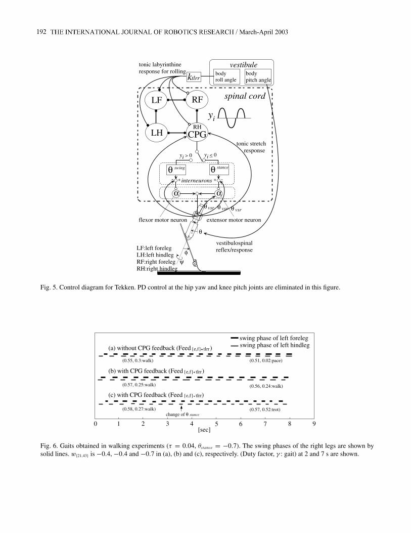
Fig. 5. Control diagram for Tekken. PD control at the hip yaw and knee pitch joints are eliminated in this figure.
(a) without CPG feedback (Feed ){e,f} tlrr
swing phase of left forelegswing phase of left hindleg
0 1 2 3 4 5 6 7 8 9[sec]
(b) with CPG feedback (Feed ){e,f} tlrr
(c) with CPG feedback (Feed ){e,f} tlrr
change of θ stance
(0.55, 0.3:walk) (0.51, 0.02:pace)
(0.57, 0.25:walk)
(0.58, 0.27:walk)
(0.56, 0.24:walk)
(0.57, 0.52:trot)
Fig. 6. Gaits obtained in walking experiments (τ = 0.04, θstance = −0.7). The swing phases of the right legs are shown bysolid lines. w{21,43} is −0.4, −0.4 and −0.7 in (a), (b) and (c), respectively. (Duty factor, γ : gait) at 2 and 7 s are shown.
Fukuoka, Kimura, and Cohen / Adaptive Dynamic Walking of A Quadruped Robot 7
2.5. Reflexes and Responses
It is well known in physiology that
• some sensory stimuli modify CPG activity and reflexiveresponses to sensory stimuli are phase-dependent underCPG activity (Cohen and Boothe 1999).
Such interaction between CPG activity and a sensory stimulusis very important for adaptation and corresponds to the nec-essary conditions described in physical terms in Section 2.4.
For example, the reflex to a stimulus on the paw dorsumin the walking of a cat depends on whether flexor or extensormuscles are active (Cohen and Boothe 1999). That is,
• when flexor muscles are active, the leg is flexed in orderto escape from the stimulus;
• when extensor muscles are active, the leg is stronglyextended in order to prevent the cat from falling down.
We call these the “flexor reflex” and the “extensor reflex”,respectively, and we assume that the phase signal from theCPG of the leg switches such reflexes. The flexor and ex-tensor reflexes contribute to satisfy the conditions (a) and (b),respectively. In Patrush, the stumbling of a swinging leg on anobstacle was detected by the force sensor, and the flexor or ex-tensor reflex was activated afterwards. However, the problemwas that the robot easily fell down due to the delayed flexingmotion caused by the delay of sensing and large inertia of theleg while walking with a short cyclic period. Therefore, wesubstitute the flexor reflex for the passive ankle joint mecha-nism described in Section 2.1 utilizing the fact that the colli-sion with a forward obstacle occurs in the first half of a swingphase. The extensor reflex has not yet been implemented inTekken.
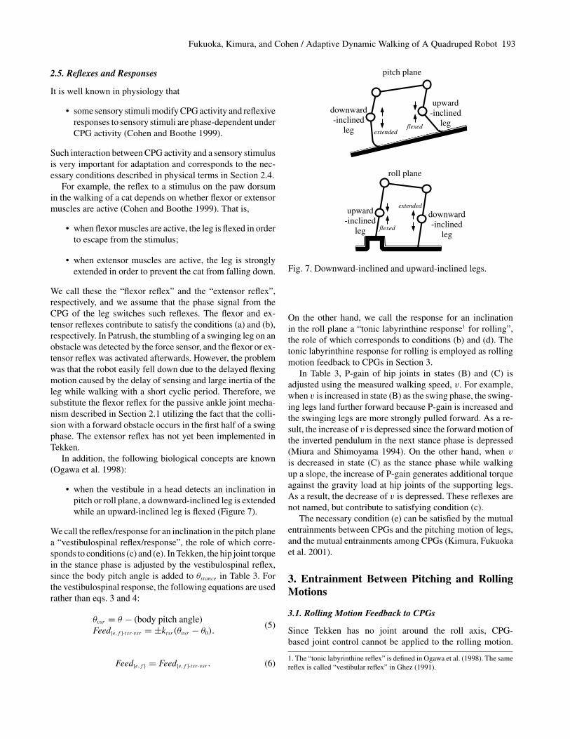
In addition, the following biological concepts are known(Ogawa et al. 1998):
• when the vestibule in a head detects an inclination inpitch or roll plane, a downward-inclined leg is extendedwhile an upward-inclined leg is flexed (Figure 7).
We call the reflex/response for an inclination in the pitch planea “vestibulospinal reflex/response”, the role of which corre-sponds to conditions (c) and (e). In Tekken, the hip joint torquein the stance phase is adjusted by the vestibulospinal reflex,since the body pitch angle is added to θstance in Table 3. Forthe vestibulospinal response, the following equations are usedrather than eqs. 3 and 4:
θvsr = θ − (body pitch angle)Feed{e,f }·tsr·vsr = ±ktsr (θvsr − θ0).
(5)
Feed{e,f } = Feed{e,f }·tsr·vsr . (6)
roll plane
upward-inclined
leg
downward-inclined
leg
pitch plane
upward-inclined
leg
downward-inclined
leg flexed
flexed
extended
extended
Fig. 7. Downward-inclined and upward-inclined legs.
On the other hand, we call the response for an inclinationin the roll plane a “tonic labyrinthine response1 for rolling”,the role of which corresponds to conditions (b) and (d). Thetonic labyrinthine response for rolling is employed as rollingmotion feedback to CPGs in Section 3.
In Table 3, P-gain of hip joints in states (B) and (C) isadjusted using the measured walking speed, v. For example,when v is increased in state (B) as the swing phase, the swing-ing legs land further forward because P-gain is increased andthe swinging legs are more strongly pulled forward. As a re-sult, the increase of v is depressed since the forward motion ofthe inverted pendulum in the next stance phase is depressed(Miura and Shimoyama 1994). On the other hand, when vis decreased in state (C) as the stance phase while walkingup a slope, the increase of P-gain generates additional torqueagainst the gravity load at hip joints of the supporting legs.As a result, the decrease of v is depressed. These reflexes arenot named, but contribute to satisfying condition (c).
The necessary condition (e) can be satisfied by the mutualentrainments between CPGs and the pitching motion of legs,and the mutual entrainments among CPGs (Kimura, Fukuokaet al. 2001).
3. Entrainment Between Pitching and RollingMotions
3.1. Rolling Motion Feedback to CPGs
Since Tekken has no joint around the roll axis, CPG-based joint control cannot be applied to the rolling motion.
1. The “tonic labyrinthine reflex” is defined in Ogawa et al. (1998). The samereflex is called “vestibular reflex” in Ghez (1991).
8 THE INTERNATIONAL JOURNAL OF ROBOTICS RESEARCH / February 2003
However, since a dynamic system similar to an inverted pen-dulum appears in the two-legged stance phase, a rolling mo-tion is naturally generated in most of the gaits as a result. Theamplitude of the rolling motion generated by walking on flatterrain is determined mainly by the gait, duty factor, and theperiod of the pitching motion cycle. As described by condition(d) in Section 2.4, the change of the phase difference betweenthe rolling motion of the body and the pitching motion of legsdisturbs stable walking. Since the feedback to CPGs describedin Section 2 does not include the sensory signal from rollingmotion, it is difficult to fix the phase difference between thesetwo motions.
Therefore, we input the body angle around the roll axis tothe CPGs as a feedback signal expressed by eq. (7) in orderto synchronize rolling motion and pitching motion (upper-leftpart of Figure 5).
Feede·t lrr = δ(leg) ktlrr × (body roll angle)Feedf ·t lrr = −Feede·t lrr
(7)
δ(leg) ={
1, if leg is a right leg;−1, otherwise
Feede = Feede·tsr·vsr + Feede·t lrrFeedf = Feedf ·tsr·vsr + Feedf ·t lrr .
(8)
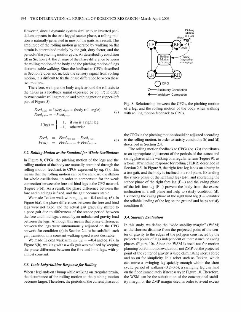
3.2. Rolling Motion as the Standard for Whole Oscillations
In Figure 8, CPGs, the pitching motion of the legs and therolling motion of the body are mutually entrained through therolling motion feedback to CPGs expressed by eq. (7). Thismeans that the rolling motion can be the standard oscillationfor whole oscillations, in order to compensate for the weakconnection between the fore and hind legs in the CPG network(Figure 3(b)). As a result, the phase difference between thefore and hind legs is fixed, and the gait becomes stable.
We made Tekken walk with w{21,43} = −0.4 and eq. (6). InFigure 6(a), the phase differences between the fore and hindlegs were not fixed, and the actual gait gradually shifted toa pace gait due to differences of the stance period betweenthe fore and hind legs, caused by an unbalanced gravity loadbetween the legs. Although this means that phase differencesbetween the legs were autonomously adjusted on the CPGnetwork for condition (e) in Section 2.4 to be satisfied, suchgait transition in a constant walking speed is not desirable.
We made Tekken walk with w{21,43} = −0.4 and eq. (8). InFigure 6(b), walking with a walk gait was realized by keepingthe phase difference between the fore and hind legs, with γalmost constant.
3.3. Tonic Labyrinthine Response for Rolling
When a leg lands on a bump while walking on irregular terrain,the disturbance of the rolling motion to the pitching motionbecomes larger. Therefore, the periods of the current phases of
Excitatory Connection
Inhibitory Connection
RollingMotion
of a Body
PitchingMotionof a Leg
angle
phase(supporting / swinging)
phase
Fig. 8. Relationship between the CPGs, the pitching motionof a leg, and the rolling motion of the body when walkingwith rolling motion feedback to CPGs.
the CPGs in the pitching motion should be adjusted accordingto the rolling motion, in order to satisfy conditions (b) and (d)described in Section 2.4.
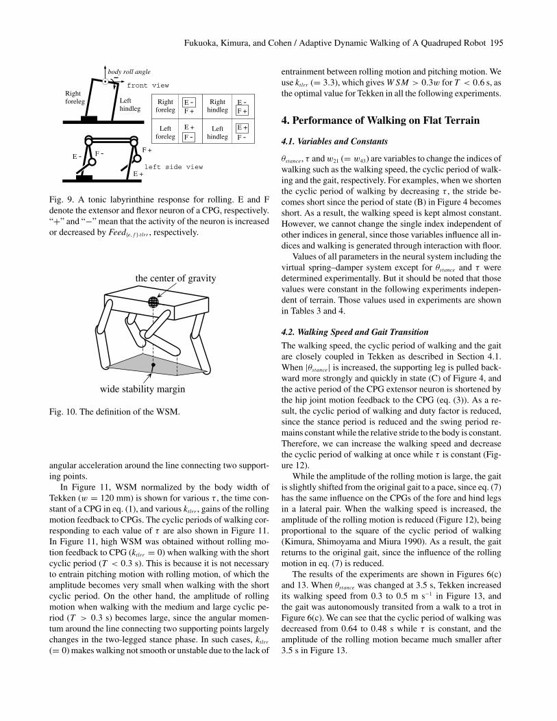
The rolling motion feedback to CPGs (eq. (7)) contributesto an appropriate adjustment of the periods of the stance andswing phases while walking on irregular terrain (Figure 9), asa tonic labyrinthine response for rolling (TLRR) described inSection 2.5. In Figure 9, the right fore leg lands on a bump ina trot gait, and the body is inclined in a roll plane. Extendingthe stance phase of the left hind leg (E+), and shortening thestance phase of the right fore leg (E−) and the swing phaseof the left fore leg (F−) prevent the body from the excessinclination in a roll plane and help to satisfy condition (d).Extending the swing phase of the right hind leg (F+) enablesthe reliable landing of the leg on the ground and helps satisfycondition (b).
3.4. Stability Evaluation
In this study, we define the “wide stability margin” (WSM)as the shortest distance from the projected point of the cen-ter of gravity to the edges of the polygon constructed by theprojected points of legs independent of their stance or swingphases (Figure 10). Since the WSM is used not for motionplanning but for motion evaluation, not ZMP but the projectedpoint of the center of gravity is used eliminating inertia forceand so on for simplicity. In a robot such as Tekken, whichcan move a swinging leg quickly enough within the shortcyclic period of walking (0.2–0.6), a swinging leg can landon the floor immediately if necessary in Figure 10. Therefore,the WSM can be the substitution of the conventional stabil-ity margin or the ZMP margin used in order to avoid excess
Fukuoka, Kimura, and Cohen / Adaptive Dynamic Walking of A Quadruped Robot 9
F -
E +
E -F +
Lefthindleg
Rightforeleg
body roll angle
Rightforeleg
Leftforeleg
Righthindleg
Lefthindleg
E -F +
E -F +
E +
F -E +
F -
front view
left side view
Fig. 9. A tonic labyrinthine response for rolling. E and Fdenote the extensor and flexor neuron of a CPG, respectively.“+” and “−” mean that the activity of the neuron is increasedor decreased by Feed{e,f }·t lrr , respectively.
wide stability margin
the center of gravity
Fig. 10. The definition of the WSM.
angular acceleration around the line connecting two support-ing points.
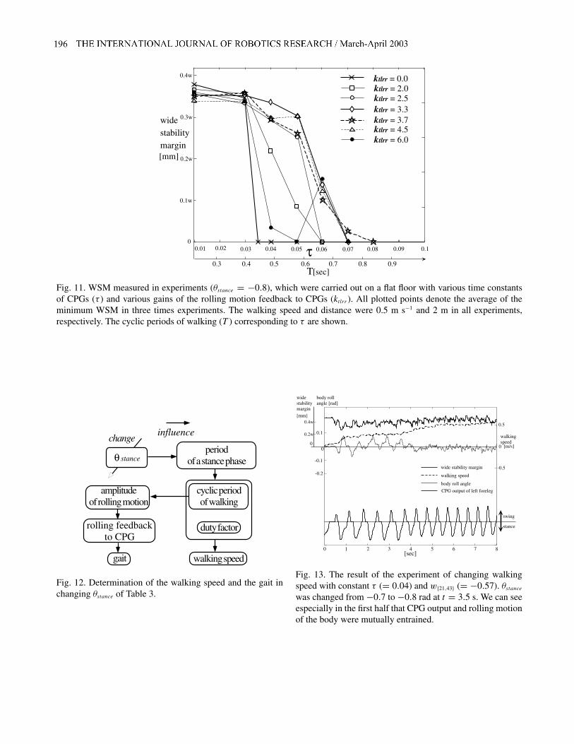
In Figure 11, WSM normalized by the body width ofTekken (w = 120 mm) is shown for various τ , the time con-stant of a CPG in eq. (1), and various ktlrr , gains of the rollingmotion feedback to CPGs. The cyclic periods of walking cor-responding to each value of τ are also shown in Figure 11.In Figure 11, high WSM was obtained without rolling mo-tion feedback to CPG (ktlrr = 0) when walking with the shortcyclic period (T < 0.3 s). This is because it is not necessaryto entrain pitching motion with rolling motion, of which theamplitude becomes very small when walking with the shortcyclic period. On the other hand, the amplitude of rollingmotion when walking with the medium and large cyclic pe-riod (T > 0.3 s) becomes large, since the angular momen-tum around the line connecting two supporting points largelychanges in the two-legged stance phase. In such cases, ktlrr(= 0) makes walking not smooth or unstable due to the lack of
entrainment between rolling motion and pitching motion. Weuse ktlrr (= 3.3), which givesWSM > 0.3w for T < 0.6 s, asthe optimal value for Tekken in all the following experiments.
4. Performance of Walking on Flat Terrain
4.1. Variables and Constants
θstance, τ andw21 (= w43) are variables to change the indices ofwalking such as the walking speed, the cyclic period of walk-ing and the gait, respectively. For examples, when we shortenthe cyclic period of walking by decreasing τ , the stride be-comes short since the period of state (B) in Figure 4 becomesshort. As a result, the walking speed is kept almost constant.However, we cannot change the single index independent ofother indices in general, since those variables influence all in-dices and walking is generated through interaction with floor.
Values of all parameters in the neural system including thevirtual spring–damper system except for θstance and τ weredetermined experimentally. But it should be noted that thosevalues were constant in the following experiments indepen-dent of terrain. Those values used in experiments are shownin Tables 3 and 4.
4.2. Walking Speed and Gait Transition
The walking speed, the cyclic period of walking and the gaitare closely coupled in Tekken as described in Section 4.1.When |θstance| is increased, the supporting leg is pulled back-ward more strongly and quickly in state (C) of Figure 4, andthe active period of the CPG extensor neuron is shortened bythe hip joint motion feedback to the CPG (eq. (3)). As a re-sult, the cyclic period of walking and duty factor is reduced,since the stance period is reduced and the swing period re-mains constant while the relative stride to the body is constant.Therefore, we can increase the walking speed and decreasethe cyclic period of walking at once while τ is constant (Fig-ure 12).
While the amplitude of the rolling motion is large, the gaitis slightly shifted from the original gait to a pace, since eq. (7)has the same influence on the CPGs of the fore and hind legsin a lateral pair. When the walking speed is increased, theamplitude of the rolling motion is reduced (Figure 12), beingproportional to the square of the cyclic period of walking(Kimura, Shimoyama and Miura 1990). As a result, the gaitreturns to the original gait, since the influence of the rollingmotion in eq. (7) is reduced.
The results of the experiments are shown in Figures 6(c)and 13. When θstance was changed at 3.5 s, Tekken increasedits walking speed from 0.3 to 0.5 m s−1 in Figure 13, andthe gait was autonomously transited from a walk to a trot inFigure 6(c). We can see that the cyclic period of walking wasdecreased from 0.64 to 0.48 s while τ is constant, and theamplitude of the rolling motion became much smaller after3.5 s in Figure 13.
10 THE INTERNATIONAL JOURNAL OF ROBOTICS RESEARCH / February 2003
0.3 0.4 0.5 0.6 0.7 0.8 0.9
0.02 0.03 0.04 0.05 0.06τ0
0.01 0.07 0.08 0.09 0.1
ktlrr = 0.0
ktlrr = 6.0ktlrr = 4.5ktlrr = 3.7ktlrr = 3.3ktlrr = 2.5ktlrr = 2.0
[mm]
widestabilitymargin
0.4w
0.3w
0.2w
0.1w
T[sec]
Fig. 11. WSM measured in experiments (θstance = −0.8), which were carried out on a flat floor with various time constantsof CPGs (τ ) and various gains of the rolling motion feedback to CPGs (ktlrr). All plotted points denote the average of theminimum WSM in three times experiments. The walking speed and distance were 0.5 m s−1 and 2 m in all experiments,respectively. The cyclic periods of walking (T ) corresponding to τ are shown.
periodof a stance phase
duty factor
cyclic periodof walking
amplitudeof rolling motion
gait
rolling feedbackto CPG
walking speed
change
θ stance
influence
Fig. 12. Determination of the walking speed and the gait inchanging θstance of Table 3.
-0.1
0.1
0
1 2 3 4 5 6 7 80[sec]
-0.2
0
0.5
-0.5
[m/s]
walking speed
body roll angle
CPG output of left foreleg
walkingspeed
body rollangle [rad]
widestabilitymargin[mm]
wide stability margin
0
0.4w
0.2w
swing
stance
Fig. 13. The result of the experiment of changing walkingspeed with constant τ (= 0.04) and w{21,43} (= −0.57). θstancewas changed from −0.7 to −0.8 rad at t = 3.5 s. We can seeespecially in the first half that CPG output and rolling motionof the body were mutually entrained.
Fukuoka, Kimura, and Cohen / Adaptive Dynamic Walking of A Quadruped Robot 11
τ = 0.01(Τ=0.28[s], approx.)
100
200
300
400
500
600
700
800
900
1000
0.1 0.2 0.3 0.4 0.5
τ = 0.05
τ = 0.03
0
walking speed[m/s]
[J/m]
energyconsumption
T=0.7[s]T=0.6[s]
T=0.4[s]T=0.5[s]
T=0.37[s]
t = 0 ~ 3 [sec] t = 3 ~ [sec]
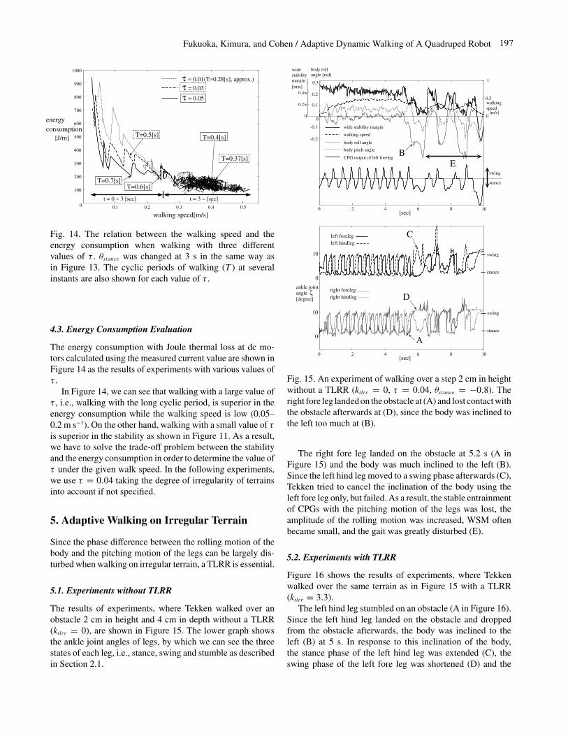
Fig. 14. The relation between the walking speed and theenergy consumption when walking with three differentvalues of τ . θstance was changed at 3 s in the same way asin Figure 13. The cyclic periods of walking (T ) at severalinstants are also shown for each value of τ .
4.3. Energy Consumption Evaluation
The energy consumption with Joule thermal loss at dc mo-tors calculated using the measured current value are shown inFigure 14 as the results of experiments with various values ofτ .
In Figure 14, we can see that walking with a large value ofτ , i.e., walking with the long cyclic period, is superior in theenergy consumption while the walking speed is low (0.05–0.2 m s−1). On the other hand, walking with a small value of τis superior in the stability as shown in Figure 11. As a result,we have to solve the trade-off problem between the stabilityand the energy consumption in order to determine the value ofτ under the given walk speed. In the following experiments,we use τ = 0.04 taking the degree of irregularity of terrainsinto account if not specified.
5. Adaptive Walking on Irregular Terrain
Since the phase difference between the rolling motion of thebody and the pitching motion of the legs can be largely dis-turbed when walking on irregular terrain, a TLRR is essential.
5.1. Experiments without TLRR
The results of experiments, where Tekken walked over anobstacle 2 cm in height and 4 cm in depth without a TLRR(ktlrr = 0), are shown in Figure 15. The lower graph showsthe ankle joint angles of legs, by which we can see the threestates of each leg, i.e., stance, swing and stumble as describedin Section 2.1.
2 4 6 8 10
[m/s]
0.5
1
0
-0.1
0.1
0
-0.2
0.2
0.3
[sec]0
walking speed
body roll angle
body pitch angle
wide stability margin
0
0.4w
0.2w walkingspeed
BCPG output of left foreleg
swing
stance
body rollangle [rad]
widestabilitymargin[mm]
ankle jointangle[degree]
0
10
left forelegleft hindleg
right forelegright hindleg
2 4 6 8 10[sec]
0
ζ
swing
stance
0
10 swing
stance
C
A
D
E
Fig. 15. An experiment of walking over a step 2 cm in heightwithout a TLRR (ktlrr = 0, τ = 0.04, θstance = −0.8). Theright fore leg landed on the obstacle at (A) and lost contact withthe obstacle afterwards at (D), since the body was inclined tothe left too much at (B).
The right fore leg landed on the obstacle at 5.2 s (A inFigure 15) and the body was much inclined to the left (B).Since the left hind leg moved to a swing phase afterwards (C),Tekken tried to cancel the inclination of the body using theleft fore leg only, but failed. As a result, the stable entrainmentof CPGs with the pitching motion of the legs was lost, theamplitude of the rolling motion was increased, WSM oftenbecame small, and the gait was greatly disturbed (E).
5.2. Experiments with TLRR
Figure 16 shows the results of experiments, where Tekkenwalked over the same terrain as in Figure 15 with a TLRR(ktlrr = 3.3).
The left hind leg stumbled on an obstacle (A in Figure 16).Since the left hind leg landed on the obstacle and droppedfrom the obstacle afterwards, the body was inclined to theleft (B) at 5 s. In response to this inclination of the body,the stance phase of the left hind leg was extended (C), theswing phase of the left fore leg was shortened (D) and the
12 THE INTERNATIONAL JOURNAL OF ROBOTICS RESEARCH / February 2003
2 4 6 8 10
walking speed
body roll angle
body pitch angle
[m/s]
0.5
1
0
-0.1
0.1
0
-0.2
0.2
0.3
[sec]0
walkingspeed
widestability margin
B
0
0.4w
0.2w
swing
stance
CPG output of left foreleg
body rollangle [rad]
widestabilitymargin
[mm]
left forelegleft hindleg
right foreleg
right hindleg
2 4 6 8 10[sec]
0
A
Fankle jointangle[degree]
0
10
ζ
0
10
C
D
E
swing
stance
swing
stance
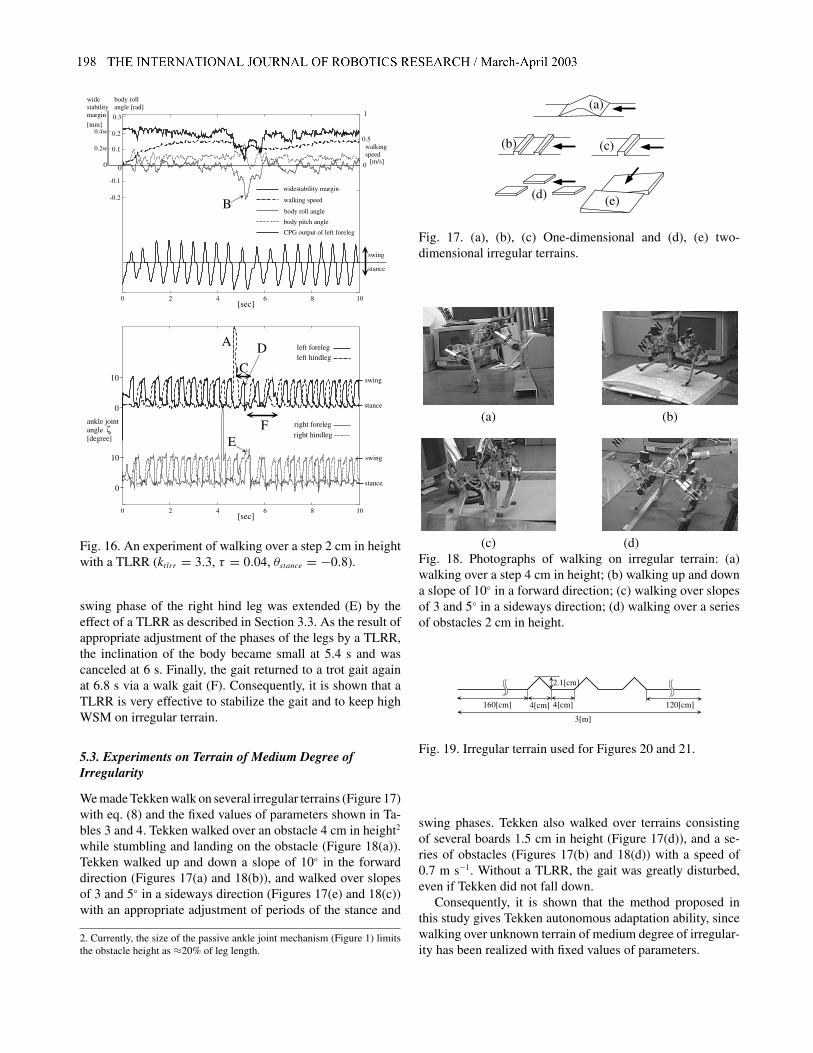
Fig. 16. An experiment of walking over a step 2 cm in heightwith a TLRR (ktlrr = 3.3, τ = 0.04, θstance = −0.8).
swing phase of the right hind leg was extended (E) by theeffect of a TLRR as described in Section 3.3. As the result ofappropriate adjustment of the phases of the legs by a TLRR,the inclination of the body became small at 5.4 s and wascanceled at 6 s. Finally, the gait returned to a trot gait againat 6.8 s via a walk gait (F). Consequently, it is shown that aTLRR is very effective to stabilize the gait and to keep highWSM on irregular terrain.
5.3. Experiments on Terrain of Medium Degree ofIrregularity
We made Tekken walk on several irregular terrains (Figure 17)with eq. (8) and the fixed values of parameters shown in Ta-bles 3 and 4. Tekken walked over an obstacle 4 cm in height2
while stumbling and landing on the obstacle (Figure 18(a)).Tekken walked up and down a slope of 10◦ in the forwarddirection (Figures 17(a) and 18(b)), and walked over slopesof 3 and 5◦ in a sideways direction (Figures 17(e) and 18(c))with an appropriate adjustment of periods of the stance and
2. Currently, the size of the passive ankle joint mechanism (Figure 1) limitsthe obstacle height as ≈20% of leg length.
(e)(d)
(c)
(a)
(b)
Fig. 17. (a), (b), (c) One-dimensional and (d), (e) two-dimensional irregular terrains.
(a) (b)
(c) (d)Fig. 18. Photographs of walking on irregular terrain: (a)walking over a step 4 cm in height; (b) walking up and downa slope of 10◦ in a forward direction; (c) walking over slopesof 3 and 5◦ in a sideways direction; (d) walking over a seriesof obstacles 2 cm in height.
2.1[cm]
3[m]
4[cm] 4[cm]160[cm] 120[cm]
Fig. 19. Irregular terrain used for Figures 20 and 21.
swing phases. Tekken also walked over terrains consistingof several boards 1.5 cm in height (Figure 17(d)), and a se-ries of obstacles (Figures 17(b) and 18(d)) with a speed of0.7 m s−1. Without a TLRR, the gait was greatly disturbed,even if Tekken did not fall down.
Consequently, it is shown that the method proposed inthis study gives Tekken autonomous adaptation ability, sincewalking over unknown terrain of medium degree of irregular-ity has been realized with fixed values of parameters.

Fukuoka, Kimura, and Cohen / Adaptive Dynamic Walking of A Quadruped Robot 13
5.4. How to Obtain Good Performance on Irregular Terrainunder Trade-off of Stability and Energy Consumption
In Section 4.3, we mentioned the trade-off problem betweenthe stability and the energy consumption in order to determinethe value of τ . In this study, we employ the following eq. (9)in order to change τ according to the WSM measured usingjoint angle sensors. Equation (9) means that we choose thelarge value of τ while the WSM is high in order to decreasethe energy consumption, and we choose the small value of τwhile the WSM is low in order to increase the WSM.
τ = 0.12(WSM)/w (9)
where WSM is normalized by the body width of Tekken (w =120 mm).
Figures 20 and 21 show the results of experiments, whereTekken walked over the terrain shown in Figure 19 with thesmall constant value of τ (= 0.005) and the various values ofτ calculated using eq. (9).
In Figure 20, we can see that the minimum WSM for theconstant value of τ is ≈ 0.25w on the irregular terrain andstable walking was obtained, since τ is very small. On theother hand, when walking with the various values of τ , theWSM became small (0.18w) on the irregular terrain at 9.3 s.But the relatively small values of τ (= 0.02) calculated byeq. (9) made the cyclic period of walking short instantly, in-creased WSM up to 0.25w and prevented Tekken from fallingdown. The walking with the large constant value of τ (= 0.05)became unstable on the irregular terrain.
In Figure 21, the energy consumption with the small con-stant value τ = 0.005 is larger than that with the vari-ous values of τ (0.02–0.065) at the dominant walking speed(0.3 m s−1). Since the energy consumption in area B corre-sponds to the instant energy consumed for adaptation to irreg-ular terrain, the time integration of those energy is not large.As a result, the integration of the energy consumption was1020 J when walking with the constant value of τ (= 0.005)and 650 J when walking with the various value of τ . Conse-quently, it was shown that stable walking with the low energyconsumption was obtained using eq. (9).
6. Discussion
6.1. Coupled-dynamics-based Motion Generation
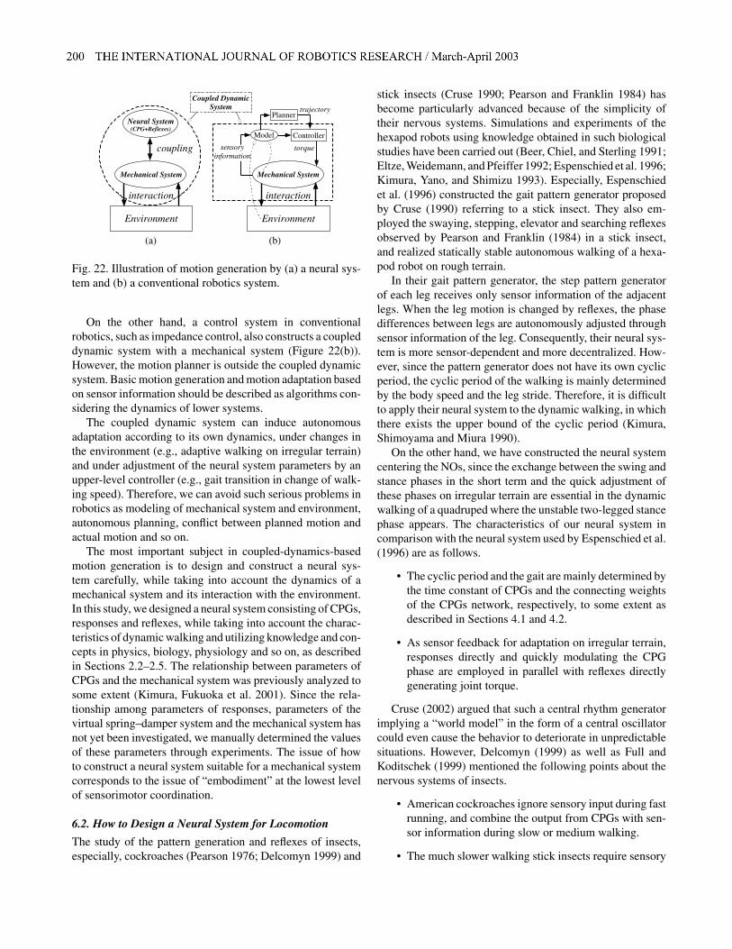
Motion generation based on biological concepts is illustratedas Figure 22(a), where a neural system and a mechanical sys-tem have their own nonlinear dynamics. The characteristic ofthis method is that there is no adaptation through motion plan-ning. These two dynamic systems are coupled to each other,generating motion by interacting with the environment emer-gently and adaptively (Taga, Yamaguchi, and Shimizu 1991;Taga 1995). We call this method “coupled-dynamics-basedmotion generation”.
0.2W
0.3W
0.4W
0.5W
2 4 6 8 10 12 1400.02
0.03
0.04
0.05
0.06
0.07
τ(eq(9))wide stabilitymargin[mm]
[sec]
τ = 0.005τ : eq(9)
Fig. 20. WSM while walking over terrain shown in Figure 19(θstance = −0.7). The cyclic period of walking correspondingto the constant value τ = 0.005 is ≈0.25 s. The cyclic periodof walking corresponding to the various values of τ (0.02–0.065) is ≈0.32–0.7 s.
200
400
600
800
1000
0.05 0.1 0.2 0.3 0.4 0.50
walking speed[m/s]
[J/m]
energyconsumption
τ = 0.005τ : eq(9)
B
Fig. 21. Energy consumption while walking over terrainshown in Figure 19 with the constant value of τ (= 0.005) andthe various values of τ calculated using eq. (9). The dominantwalking speeds in both walks are almost equal (≈0.3 m s−1).
14 THE INTERNATIONAL JOURNAL OF ROBOTICS RESEARCH / February 2003
Mechanical System
interaction
Environment
Model Controller
Plannertrajectory
torquesensoryinformation
Coupled DynamicSystem
Neural System(CPG+Reflexes)
Mechanical System
coupling
interaction
Environment
(b)(a)
Fig. 22. Illustration of motion generation by (a) a neural sys-tem and (b) a conventional robotics system.
On the other hand, a control system in conventionalrobotics, such as impedance control, also constructs a coupleddynamic system with a mechanical system (Figure 22(b)).However, the motion planner is outside the coupled dynamicsystem. Basic motion generation and motion adaptation basedon sensor information should be described as algorithms con-sidering the dynamics of lower systems.
The coupled dynamic system can induce autonomousadaptation according to its own dynamics, under changes inthe environment (e.g., adaptive walking on irregular terrain)and under adjustment of the neural system parameters by anupper-level controller (e.g., gait transition in change of walk-ing speed). Therefore, we can avoid such serious problems inrobotics as modeling of mechanical system and environment,autonomous planning, conflict between planned motion andactual motion and so on.
The most important subject in coupled-dynamics-basedmotion generation is to design and construct a neural sys-tem carefully, while taking into account the dynamics of amechanical system and its interaction with the environment.In this study, we designed a neural system consisting of CPGs,responses and reflexes, while taking into account the charac-teristics of dynamic walking and utilizing knowledge and con-cepts in physics, biology, physiology and so on, as describedin Sections 2.2–2.5. The relationship between parameters ofCPGs and the mechanical system was previously analyzed tosome extent (Kimura, Fukuoka et al. 2001). Since the rela-tionship among parameters of responses, parameters of thevirtual spring–damper system and the mechanical system hasnot yet been investigated, we manually determined the valuesof these parameters through experiments. The issue of howto construct a neural system suitable for a mechanical systemcorresponds to the issue of “embodiment” at the lowest levelof sensorimotor coordination.
6.2. How to Design a Neural System for Locomotion
The study of the pattern generation and reflexes of insects,especially, cockroaches (Pearson 1976; Delcomyn 1999) and
stick insects (Cruse 1990; Pearson and Franklin 1984) hasbecome particularly advanced because of the simplicity oftheir nervous systems. Simulations and experiments of thehexapod robots using knowledge obtained in such biologicalstudies have been carried out (Beer, Chiel, and Sterling 1991;Eltze, Weidemann, and Pfeiffer 1992; Espenschied et al. 1996;Kimura, Yano, and Shimizu 1993). Especially, Espenschiedet al. (1996) constructed the gait pattern generator proposedby Cruse (1990) referring to a stick insect. They also em-ployed the swaying, stepping, elevator and searching reflexesobserved by Pearson and Franklin (1984) in a stick insect,and realized statically stable autonomous walking of a hexa-pod robot on rough terrain.
In their gait pattern generator, the step pattern generatorof each leg receives only sensor information of the adjacentlegs. When the leg motion is changed by reflexes, the phasedifferences between legs are autonomously adjusted throughsensor information of the leg. Consequently, their neural sys-tem is more sensor-dependent and more decentralized. How-ever, since the pattern generator does not have its own cyclicperiod, the cyclic period of the walking is mainly determinedby the body speed and the leg stride. Therefore, it is difficultto apply their neural system to the dynamic walking, in whichthere exists the upper bound of the cyclic period (Kimura,Shimoyama and Miura 1990).
On the other hand, we have constructed the neural systemcentering the NOs, since the exchange between the swing andstance phases in the short term and the quick adjustment ofthese phases on irregular terrain are essential in the dynamicwalking of a quadruped where the unstable two-legged stancephase appears. The characteristics of our neural system incomparison with the neural system used by Espenschied et al.(1996) are as follows.
• The cyclic period and the gait are mainly determined bythe time constant of CPGs and the connecting weightsof the CPGs network, respectively, to some extent asdescribed in Sections 4.1 and 4.2.
• As sensor feedback for adaptation on irregular terrain,responses directly and quickly modulating the CPGphase are employed in parallel with reflexes directlygenerating joint torque.
Cruse (2002) argued that such a central rhythm generatorimplying a “world model” in the form of a central oscillatorcould even cause the behavior to deteriorate in unpredictablesituations. However, Delcomyn (1999) as well as Full andKoditschek (1999) mentioned the following points about thenervous systems of insects.
• American cockroaches ignore sensory input during fastrunning, and combine the output from CPGs with sen-sor information during slow or medium walking.
• The much slower walking stick insects require sensory
Fukuoka, Kimura, and Cohen / Adaptive Dynamic Walking of A Quadruped Robot 15
input at all times, since the centrally generated patternis either extremely weak or nonexistent.
We also believe that we should use the appropriate controlmethod or neural system according to the locomotion speedas already mentioned in Section 2 using Table 1.
7. Conclusion
In the neural system model proposed in this study, the relation-ships among CPGs, sensory input, reflexes and the mechanicalsystem are simply defined, and motion generation and adap-tation are emergently induced by the coupled dynamics ofa neural system and a mechanical system by interacting withthe environment. To generate appropriate adaptation, it is nec-essary to design both the neural system and the mechanicalsystem carefully. In this study, we designed the neural systemconsisting of CPGs, responses, the stretch reflex and otherreflexes referring to biological concepts. We also designedthe passive spring-and-lock mechanism at the ankle joint asa mechanical implementation of the flexor reflex. The virtualspring–damper system became effective since Tekken had alight-weighted leg and high backdrivability in each joint.
The physical oscillations, such as the motion of the virtualspring–damper system of each leg and the rolling motion ofthe body, are mutually entrained with CPGs as the neuraloscillations. A CPG receives sensory input and changes theperiod of its own active phase as responses. The virtual spring–damper system also receives sensory input and outputs torqueas reflexes. The states in the virtual spring–damper system areswitched based on the phase signal of the CPG. Consequently,adaptive walking is generated through the interaction withenvironment.
References
Akazawa, K., Aldridge, J. W., Steeves, J. D., and Stein, R.B.1982. Modulation of stretch reflexes during locomotionin the mesencephalic cat. Journal of Physiology 329:553–567.
Beer, R. D., Chiel, H. J., and Sterling, L. S. 1991. An ArtificialInsect. American Scientist 79:444–452.
Buehler, M., Battaglia, R., Cocosco, A., Hawker, G., Sarkis,J., and Yamazaki, K. 1998. Scout: A simple quadrupedthat walks, climbs and runs. In Proc. ICRA1998, pp. 1707–1712.
Cham, J. G., Karpick, J., Clark J. E., and Cutkosky, M. R.2001. Stride period adaptation for a biomimetic runninghexapod. In Proc. ISRR2001, pp. 77–87.
Chew, C. M., Pratt, J., and Pratt, G. 1999. Blind walking ofa planar bipedal robot on sloped terrain. In Proc. ICRA99,pp. 381–386.
Cohen, A. H., and Boothe, D. L. 1999. Sensorimotor interac-tions during locomotion: principles derived from biologi-cal systems. Autonomous Robots 7(3):239–245.
Cruse, H. 1990. What mechanism coordinate leg movementin walking arthropods? Trends in Neurosciences 12:15–21.
Cruse, H. 2002. The functional sense of central oscillationsin walking. Biological Cybernetics 86:271–280.
Dean J., Kindermann, T., Schmitz, J., Schumm, M., and Cruse,H. 1999. Control of walking in the stick insect: From be-havior and physiology to modeling. Autonomous Robots7(3):271–288.
Delcomyn, F. 1999. Walking robots and the central and pe-ripheral control of locomotion in insects. AutonomousRobots 7(3):259–270.
Eltze, J., Weidemann, H. J., and Pfeiffer, F. 1992. Designof walking machines using biological principles. In Proc.IFToMM-jc, pp. 689–694.
Espenschied, K. S., Quinn, R. D., Beer, R. D., and Chiel,H. J. 1996. Biologically based distributed control and localreflexes improve rough terrain locomotion in a hexapodrobot. Robotics and Autonomous Systems 18:59–64.
Full, R. J., and Koditschek, D. E. 1999. Templates and an-chors: neuromechanical hypotheses of legged locomo-tion on land. Journal of Experimental Biology 202:3325–3332.
Full, R. J. 2000. Biological inspiration: lessons from many-legged locomotors. Robotics Research 9, Hollerbach,J. M. and Koditschek, D. E., eds, Springer, London,pp. 337–341.
Ghez, C. 1991. Posture, Principles of Neural Science 3rd edn,Kandel, E. R., Schwartz, J. H, and Jessell, T. M., eds, Ap-pleton & Lange, Norwalk, CT, p. 601.
Grillner, S. 1981. Control of locomotion in bipeds, tetrapodsand fish. Handbook of Physiology II American PhysiologySociety, Bethesda, MD, pp. 1179–1236.
Hodgins, J. K., and Raibert, M. H. 1991. Adjusting steplength for rough terrain locomotion. IEEE Transactionson Robotics and Automation 7(3):289–298.
Ijspeert, A. J. 2001. A connectionist central pattern generatorfor the aquatic and terrestrial gaits of a simulated salaman-der. Biological Cybernetics 84:331–348.
Ilg, W., Albiez, J., Jedele, H., Berns, K., and Dillmann, R.1999. Adaptive periodic movement control for the fourlegged walking machine BISAM. In Proc. ICRA1999,pp. 2354–2359.
Kajita, S., and Tani, K. 1996. Adaptive gait control of a bipedrobot based on real-time sensing of the ground. In Proc.ICRA1996, pp. 570–577.
Kimura, H., Shimoyama, I., and Miura, H. 1990. Dynamics inthe dynamic walk of a quadruped robot. Advanced Robotics4(3):283–301.
Kimura, H., Akiyama, S., and Sakurama, K. 1999. Realizationof dynamic walking and running of the quadruped usingneural oscillator. Autonomous Robots 7(3):247–258.
Kimura, H., Fukuoka, Y., and Konaga, K. 2001a. Adaptivedynamic walking of a quadruped robot using neural systemmodel. Advanced Robotics 15(8):859–876.
16 THE INTERNATIONAL JOURNAL OF ROBOTICS RESEARCH / February 2003
Kimura, H., Fukuoka, Y., Hada, Y., and Takase, K. 2001b. 3Dadaptive dynamic walking of a quadruped robot by usingneural system model. In Proc. CLAWAR2001, pp. 97–104.
Kimura, S., Yano, M., and Shimizu, H. 1993. A Self-Organizing Model of Walking Patterns of Insects, Biolog-ical Cybernetics 69:183–193.
Lewis, M. A., Etienne-Cummings, Hartmann, M. J., Xu, Z. R.,and Cohen, A. H. 2003. An in silico central pattern genera-tor: silicon oscillator, coupling, entrainment, and physicalcomputation. Biological Cybernetics 88:137–151.
Matsuoka, K. 1987. Mechanisms of frequency and patterncontrol in the neural rhythm generators. Biological Cyber-netics 56:345–353.
Miura, H., and Shimoyama, I. 1984. Dynamical walk of bipedlocomotion. International Journal of Robotics Research3(2):60–74.
Miyakoshi, S., Taga, G., Kuniyoshi, Y., and Nagakubo, A.1998. Three-dimensional bipedal stepping motion usingneural oscillators—Towards humanoid motion in the realworld. In Proc. IRSO1998, pp. 84–89.
Ogawa, T. et al., eds. 1998. Nanzando’s Medical Dictionary18th edn, Nanzando, Tokyo, p. 1211 (in Japanese).
Pearson, K. G. 1976. The control of walking. Scientific Amer-ican 234(6):72–87.
Pearson, K. G., and Franklin, R. 1984. Characteristics of legmovements and patterns of coordination in locusts walk-
ing on rough terrain. International Journal of Robotics Re-search 3:101–112.
Saranli, U., Buehler, M., and Koditschek, D. E. 2001. RHex:a simple and highly mobile hexapod robot. InternationalJournal of Robotics Research 20(7):616–631.
Taga, G., Yamaguchi, Y., and Shimizu, H. 1991. Self-organized control of bipedal locomotion by neural oscilla-tors. Biological Cybernetics 65:147–159.
Taga, G. 1995. A model of the neuro-musculo-skeletal sys-tem for human locomotion II. Real-time adaptability undervarious constraints. Biological Cybernetics 73:113–121.
Takanishi, A., Takeya, T., Karaki, H., and Kato, I. 1990. Acontrol method for dynamic biped walking under unknownexternal force. In Proc. IRSO1990, pp. 795–801.
Tsujita, K., Tsuchiya, K., and Onat, A. 2001. Adaptive GaitPattern Control of a Quadruped Locomotion Robot. InProc. IROS2001, pp. 2318–2325.
Yamaguchi, J., Takanishi, A., and Kato, I. 1994. Developmentof a biped walking robot adapting to a horizontally unevensurface. In Proc. IRSO1994, pp. 1156–1163.
Yoneda, K., Iiyama, H., and Hirose, S. 1994. Sky-hook sus-pension control of a quadruped walking vehicle. In Proc.ICRA1994, pp. 999–1004.