Yamaha Road Star Instl Guide Rev5 - Voyager Trike · obtain an OEM service manual for the vehicle...
22
YAMAHA ROAD STAR TRIKE CONVERSION CHAMPION TRIKES Installation Guide Page 1 of 22 Revision 5 Illustrations / Photography By: Terry T. Emelio Tech. Writing By Terry T. Emelio Trike Conversion Installation Guide for Yamaha Road Star Motorcycles Excluding All Warrior Models Revision 5 Champion Motorcycle Accessories International, Inc. dba Champion Sidecars 11841 Monarch Street, CA 92841 (800) 875-0949 (714) 847-0949 Fax (714) 847-1539 www.championtrikes.com CAUTION : Failure to follow these instructions can lead to serious personal injury and/or property damage and may void the warranty
Transcript of Yamaha Road Star Instl Guide Rev5 - Voyager Trike · obtain an OEM service manual for the vehicle...

YAMAHA ROAD STAR TRIKE CONVERSION
CHAMPION TRIKES
Installation Guide Page 1 of 22 Revision 5 Illustrations / Photography By: Terry T. Emelio Tech. Writing By Terry T. Emelio
Trike Conversion Installation Guide for
Yamaha Road Star Motorcycles Excluding All Warrior Models
Revision 5
Champion Motorcycle Accessories International, Inc. dba Champion Sidecars
11841 Monarch Street, CA 92841 (800) 875-0949 (714) 847-0949 Fax (714) 847-1539
www.championtrikes.com
CAUTION : Failure to follow these instructions can lead to serious personal injury and/or property damage and may void the warranty
YAMAHA ROAD STAR TRIKE CONVERSION
CHAMPION TRIKES
Installation Guide Page 2 of 22 Revision 5 Illustrations / Photography By: Terry T. Emelio Tech. Writing By Terry T. Emelio
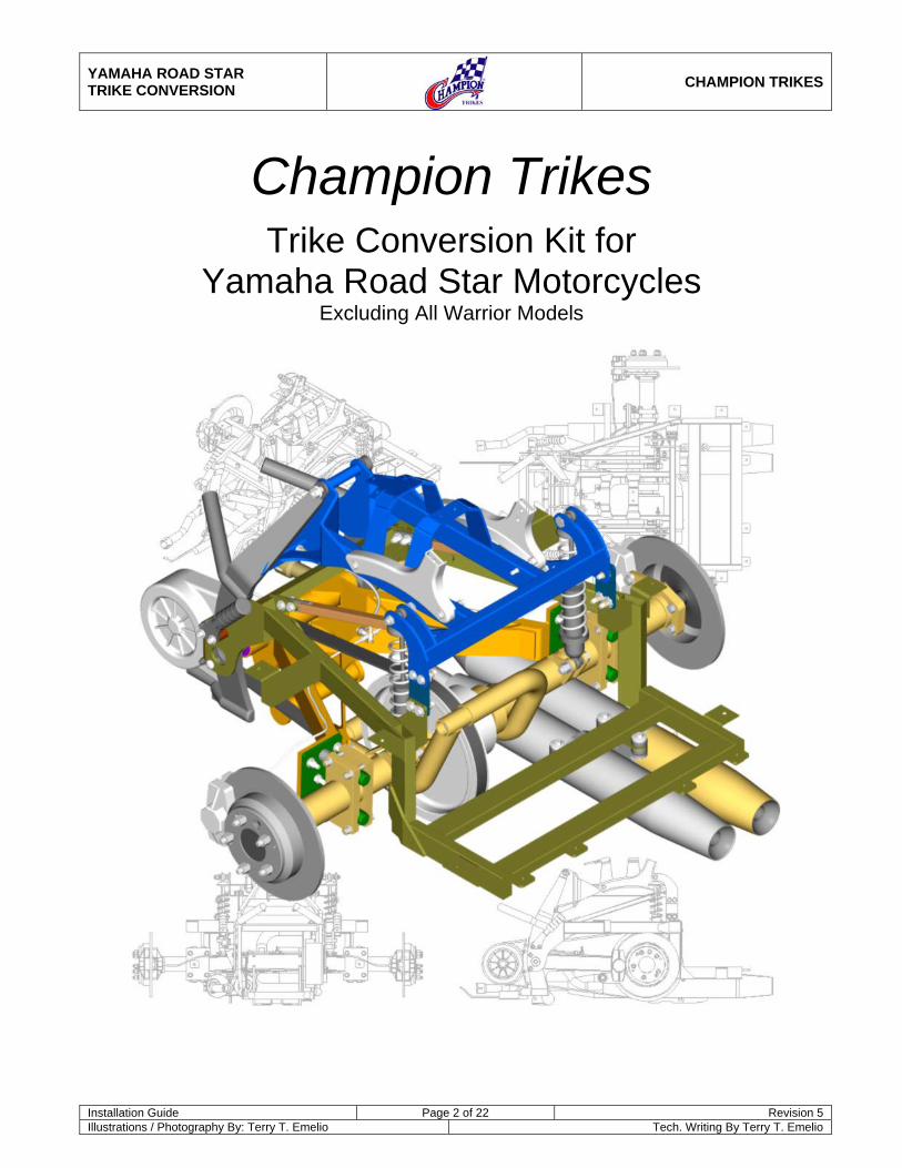
Champion Trikes
Trike Conversion Kit for Yamaha Road Star Motorcycles
Excluding All Warrior Models
YAMAHA ROAD STAR TRIKE CONVERSION
CHAMPION TRIKES
Installation Guide Page 3 of 22 Revision 5 Illustrations / Photography By: Terry T. Emelio Tech. Writing By Terry T. Emelio
Table of Contents
1 General Information .........................................................................................................................4 1.1 Installation Information ................................................................................................................................. 4 1.2 For Your Safety............................................................................................................................................. 4 1.3 Important Safety Precautions ....................................................................................................................... 4
2 Specifications ...................................................................................................................................5 3 Removal of Original Parts ...............................................................................................................6 4 Installation of Champion Trike Conversion Kit .............................................................................7
4.1 Install Drive Belt............................................................................................................................................ 7 4.2 Install Champion Swing Arm ........................................................................................................................ 7 4.3 Install Rear Drive Assembly ......................................................................................................................... 7 4.4 Install Brake Lines ...................................................................................................................................... 10 4.5 Install Seat / Shock Mount.......................................................................................................................... 10 4.6 Install Body Frame...................................................................................................................................... 11 4.7 Install Support Struts .................................................................................................................................. 12 4.8 Install Shock Absorbers.............................................................................................................................. 13 4.9 Muffler Modifications / Exhaust Installation ................................................................................................ 13 4.10 Position Muffler onto Hanger ............................................................................................................. 14 4.11 Install OEM Back Rest Brackets........................................................................................................ 16 4.12 Install Body ........................................................................................................................................ 16
5 Install Front / Rear Seat Mount Tab ..............................................................................................18 5.1 Install Passenger Foot Pegs / Boards ........................................................................................................ 18 5.2 Install Passenger Back Rest....................................................................................................................... 19 5.3 Install Rider and Passenger Seats ............................................................................................................. 19 5.4 Install Wheels ............................................................................................................................................. 19 5.5 Install Trailer Tongue (Optional) ................................................................................................................. 20
6 Part List ...........................................................................................................................................21 7 Hardware List..................................................................................................................................22

YAMAHA ROAD STAR TRIKE CONVERSION
CHAMPION TRIKES
Installation Guide Page 4 of 22 Revision 5 Illustrations / Photography By: Terry T. Emelio Tech. Writing By Terry T. Emelio
1 General Information The Champion Sidecars Trike Conversion Kit is designed with the utmost consideration to safety, quality and ease of installation. The kit comes complete with all necessary hardware and fasteners. However, it is assumed that the installer has advanced and/or professional skills in motorcycle servicing. It is recommended that installer obtain an OEM service manual for the vehicle to which the Trike Kit is to be installed.
1.1 Installation Information The information contained in this Installation Guide is intended for use by technicians of advanced and/or professional skill levels. Attempting installation without the proper training, tools and equipment could cause injury to you or others. It could also damage the vehicle or cause an unsafe condition.
1.2 For Your Safety Because this guide in intended for technicians of advanced to professional skill levels, we do not provide warnings about many basic shop safety practices. If you have not received shop safety training or do not feel confident about your knowledge of safety practices, we recommend that you do not attempt to perform the procedures described in this guide. Some of the most important general safety precautions are given below. Champion Sidecars cannot warn you of every conceivable hazard that can arise. Only you can decide whether or not you should perform a given task.
1.3 Important Safety Precautions
a. Make sure you have a clear understanding of all basic shop safety practices and that you wear appropriate clothing and use safety equipment. Be especially careful of the following:
• Read all directions before you begin, and make sure you have the tools, the parts and the skills required
to perform the tasks safely and completely.
• Protect your eyes by using proper safety glasses, goggles or face shields any time you hammer, drill, grind, pry or work around pressurized air or liquids, and springs or other stored-energy components.
• Use other protective wear when necessary, for example gloves or safety shoes. Handling hot or sharp
parts can cause severe burns or cuts.
• Protect yourself and others when you have a vehicle up in the air. Anytime you lift a vehicle, either by hoist or a jack, make sure that it is securely supported.
b. Make sure the engine is turned off before you begin work.
• Carbon Monoxide poisoning from exhaust gases: Be sure there is adequate ventilation whenever you run the engine.
• Burns from hot parts: Let the engine and exhaust system cool before working on those areas.

YAMAHA ROAD STAR TRIKE CONVERSION
CHAMPION TRIKES
Installation Guide Page 5 of 22 Revision 5 Illustrations / Photography By: Terry T. Emelio Tech. Writing By Terry T. Emelio
2 Specifications
Overall Width: 54.25”
Overall Length: 103”
Wheel Base: 68.25”
Load Capacity: 500 Lb
Tire Size: P215 / 60R / 15
Wheel Size (15”) Offset +35 mm 15x7JJ 5x4.5
Tire Pressure 20 PSI
• Suspension: “Zero-Flex” Internal Swing Arm utilizing 3 shocks, OEM shock absorber plus 2 coil over shock absorbers.
• Rear Differential:
Champion Light Weight Rear Differential Assembly.
• Brakes: Original front plus 2 high performance disc brakes at rear.
• Storage Capacity:
3.75 cubic feet. 2 full-face helmets and additional over wheel storage.
YAMAHA ROAD STAR TRIKE CONVERSION
CHAMPION TRIKES
Installation Guide Page 6 of 22 Revision 5 Illustrations / Photography By: Terry T. Emelio Tech. Writing By Terry T. Emelio
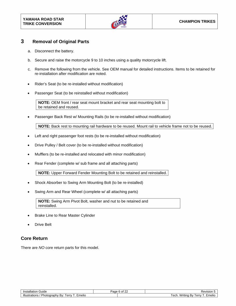
3 Removal of Original Parts
a. Disconnect the battery.
b. Secure and raise the motorcycle 9 to 10 inches using a quality motorcycle lift.
c. Remove the following from the vehicle. See OEM manual for detailed instructions. Items to be retained for re-installation after modification are noted.
• Rider’s Seat (to be re-installed without modification)
• Passenger Seat (to be reinstalled without modification)
NOTE: OEM front / rear seat mount bracket and rear seat mounting bolt to be retained and reused.
• Passenger Back Rest w/ Mounting Rails (to be re-installed without modification)
NOTE: Back rest to mounting rail hardware to be reused. Mount rail to vehicle frame not to be reused.
• Left and right passenger foot rests (to be re-installed without modification)
• Drive Pulley / Belt cover (to be re-installed without modification)
• Mufflers (to be re-installed and relocated with minor modification)
• Rear Fender (complete w/ sub frame and all attaching parts)
NOTE: Upper Forward Fender Mounting Bolt to be retained and reinstalled.
• Shock Absorber to Swing Arm Mounting Bolt (to be re-installed)
• Swing Arm and Rear Wheel (complete w/ all attaching parts)
NOTE: Swing Arm Pivot Bolt, washer and nut to be retained and reinstalled.
• Brake Line to Rear Master Cylinder
• Drive Belt
Core Return There are NO core return parts for this model.

YAMAHA ROAD STAR TRIKE CONVERSION
CHAMPION TRIKES
Installation Guide Page 7 of 22 Revision 5 Illustrations / Photography By: Terry T. Emelio Tech. Writing By Terry T. Emelio
4 Installation of Champion Trike Conversion Kit
4.1 Install Drive Belt
a. Install supplied drive belt to transmission output pulley. (Refer to OEM manual) Figure 1
b. Drive belt cover to be reinstalled later.
4.2 Install Champion Swing Arm
a. Install Champion Swing Arm to vehicle using the OEM pivot bolt, washer and nut. Figure 2
b. Attach OEM shock absorber to swing arm using OEM hardware.
c. Torque pivot bolt nut to 90 lb. ft.
d. Torque lower shock hardware to 43 lb. ft.
4.3 Install Rear Drive Assembly
a. Install tension bolts and jam nuts to adjuster plates. Figure 3
Qty per Assm Spec Description
2 M10 x 1.25 x 70 Hex Head Bolt 2 M10 x 1.25 Hex Nut
b. Install adjuster plates to rear drive pinch blocks. Hardware installs from inboard to outboard side. Snug, but do not tighten hardware at this time. Figure 4
Qty per Assm Spec Description
6 3/8-24 x 2-3/4 Hex Head Bolt 2 3/8-24 x 2-1-2 Socket Head Cap Screw
14 3/8 SAE Flat Washer 8 3/8-24 NyLoc Nut
Figure 1
Figure 2
Figure 3
Figure 4

YAMAHA ROAD STAR TRIKE CONVERSION
CHAMPION TRIKES
Installation Guide Page 8 of 22 Revision 5 Illustrations / Photography By: Terry T. Emelio Tech. Writing By Terry T. Emelio
c. Position the rear drive assembly through the drive belt and behind the swing arm, supporting both ends with jack stands or other suitable method. Figure 5
d. Remove the two bolts (use 5/8” Allen wrench) securing the left and right halves of the rear drive assembly together. Figure 6
e. Rotate the left side assembly counter clockwise enough to allow the drive belt to pass. Place the belt to the inside of the rear drive pulley. Figure 7
f. Realign the rear drive assembly halves and replace the bolts. Torque to 100 ft. lbs.
Figure 5
Figure 6
Figure 7
YAMAHA ROAD STAR TRIKE CONVERSION
CHAMPION TRIKES
Installation Guide Page 9 of 22 Revision 5 Illustrations / Photography By: Terry T. Emelio Tech. Writing By Terry T. Emelio
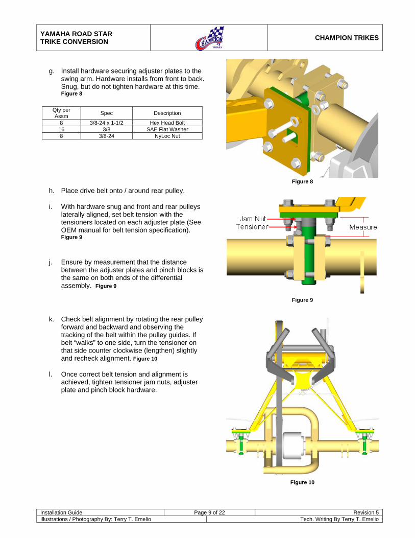
g. Install hardware securing adjuster plates to the swing arm. Hardware installs from front to back. Snug, but do not tighten hardware at this time. Figure 8
Qty per Assm Spec Description
8 3/8-24 x 1-1/2 Hex Head Bolt 16 3/8 SAE Flat Washer 8 3/8-24 NyLoc Nut
h. Place drive belt onto / around rear pulley.
i. With hardware snug and front and rear pulleys laterally aligned, set belt tension with the tensioners located on each adjuster plate (See OEM manual for belt tension specification). Figure 9
j. Ensure by measurement that the distance between the adjuster plates and pinch blocks is the same on both ends of the differential assembly. Figure 9
k. Check belt alignment by rotating the rear pulley forward and backward and observing the tracking of the belt within the pulley guides. If belt “walks” to one side, turn the tensioner on that side counter clockwise (lengthen) slightly and recheck alignment. Figure 10
l. Once correct belt tension and alignment is achieved, tighten tensioner jam nuts, adjuster plate and pinch block hardware.
Figure 8
Figure 9
Figure 10
YAMAHA ROAD STAR TRIKE CONVERSION
CHAMPION TRIKES
Installation Guide Page 10 of 22 Revision 5 Illustrations / Photography By: Terry T. Emelio Tech. Writing By Terry T. Emelio
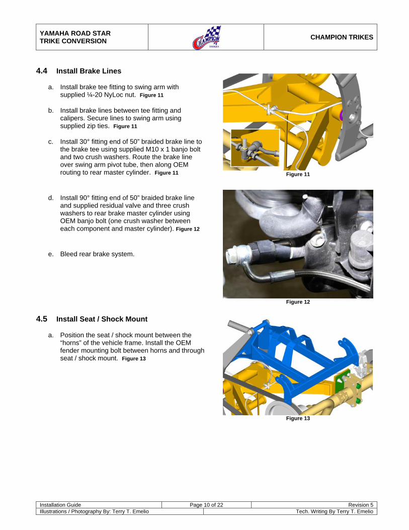
4.4 Install Brake Lines
a. Install brake tee fitting to swing arm with supplied ¼-20 NyLoc nut. Figure 11
b. Install brake lines between tee fitting and calipers. Secure lines to swing arm using supplied zip ties. Figure 11
c. Install 30° fitting end of 50” braided brake line to the brake tee using supplied M10 x 1 banjo bolt and two crush washers. Route the brake line over swing arm pivot tube, then along OEM routing to rear master cylinder. Figure 11
d. Install 90° fitting end of 50” braided brake line and supplied residual valve and three crush washers to rear brake master cylinder using OEM banjo bolt (one crush washer between each component and master cylinder). Figure 12
e. Bleed rear brake system.
4.5 Install Seat / Shock Mount
a. Position the seat / shock mount between the “horns” of the vehicle frame. Install the OEM fender mounting bolt between horns and through seat / shock mount. Figure 13
Figure 11
Figure 12
Figure 13

YAMAHA ROAD STAR TRIKE CONVERSION
CHAMPION TRIKES
Installation Guide Page 11 of 22 Revision 5 Illustrations / Photography By: Terry T. Emelio Tech. Writing By Terry T. Emelio
b. Install hardware through vehicle frame and seat / shock mount as shown. Figure 14
Qty per Assm Spec Description
2 M10 x 1.25 x 45 Hex Head Bolt 4 M10 Washer 2 M10 x 1.25 NyLoc Nut
c. Tighten all shock / seat mount hardware. Torque upper hardware (at “horns”) to 64 lb. ft.
4.6 Install Body Frame
a. Replace drive pulley / belt cover to vehicle transmission.
b. Position body frame to vehicle. Figure 15
c. Install hardware as shown. Ensure engine side plates are between vehicle frame and body frame plates. Do not tighten at this time. Figure 16
Qty per Assm Spec Description
4 M10 x 1.25 x 30 Hex Head Bolt 4 M10 Washer
Figure 14
Figure 15
Figure 16

YAMAHA ROAD STAR TRIKE CONVERSION
CHAMPION TRIKES
Installation Guide Page 12 of 22 Revision 5 Illustrations / Photography By: Terry T. Emelio Tech. Writing By Terry T. Emelio
d. Install left and right body frame hanger plates between seat / shock mount and body frame as shown. Figure 17
Qty per Assm Spec Description
8 3/8-24 x 1-1/2 Hex Head Bolt 16 5/16 USS Flat Washer 16 3/8 Star Lock Washer 8 3/8-24 NyLoc Nut
e. Tighten all body frame hardware.
4.7 Install Support Struts
a. Install left and right support struts between seat / shock mount and body frame as shown. Struts mount inboard of upper and lower tabs. Figure 18
Qty per Assm Spec Description
8 3/8-24 x 1-1/4 Hex Head Bolt 16 5/16 USS Flat Washer 8 3/8-24 NyLoc Nut
b. Tighten hardware.
Figure 17
Figure 18
YAMAHA ROAD STAR TRIKE CONVERSION
CHAMPION TRIKES
Installation Guide Page 13 of 22 Revision 5 Illustrations / Photography By: Terry T. Emelio Tech. Writing By Terry T. Emelio
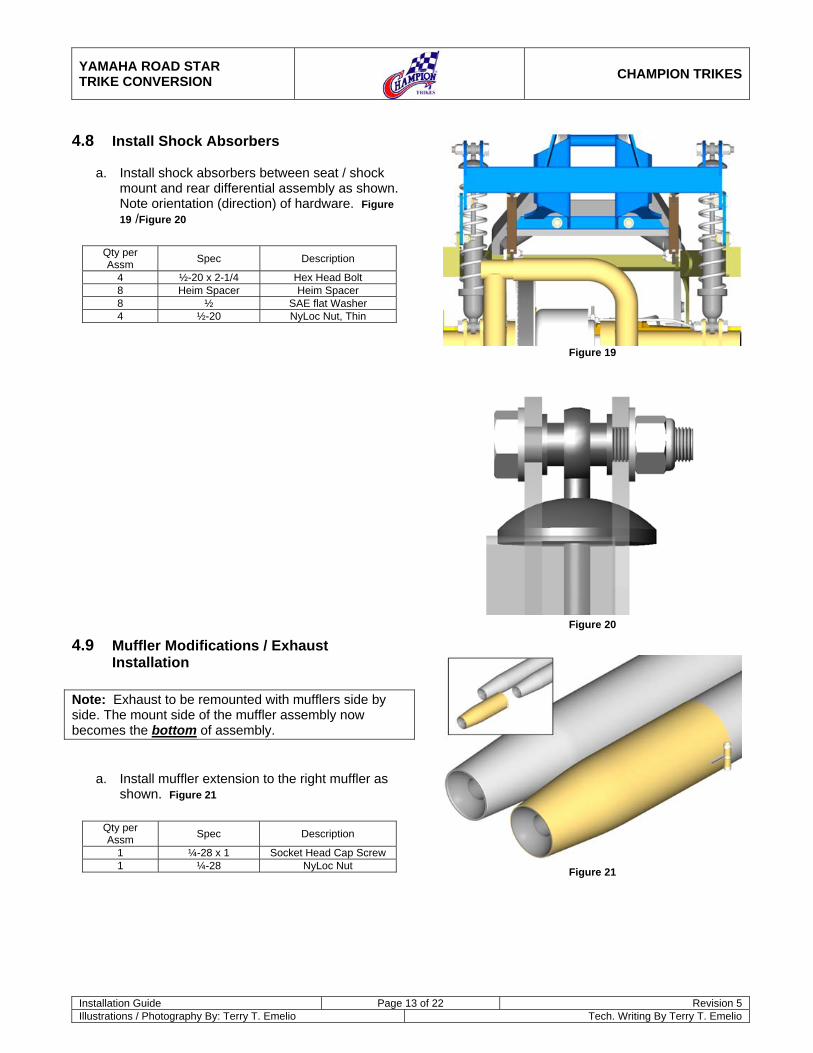
4.8 Install Shock Absorbers
a. Install shock absorbers between seat / shock mount and rear differential assembly as shown. Note orientation (direction) of hardware. Figure 19 /Figure 20
Qty per Assm Spec Description
4 ½-20 x 2-1/4 Hex Head Bolt 8 Heim Spacer Heim Spacer 8 ½ SAE flat Washer 4 ½-20 NyLoc Nut, Thin
4.9 Muffler Modifications / Exhaust Installation
Note: Exhaust to be remounted with mufflers side by side. The mount side of the muffler assembly now becomes the bottom of assembly.
a. Install muffler extension to the right muffler as shown. Figure 21
Qty per Assm Spec Description
1 ¼-28 x 1 Socket Head Cap Screw 1 ¼-28 NyLoc Nut
Figure 19
Figure 20
Figure 21

YAMAHA ROAD STAR TRIKE CONVERSION
CHAMPION TRIKES
Installation Guide Page 14 of 22 Revision 5 Illustrations / Photography By: Terry T. Emelio Tech. Writing By Terry T. Emelio
b. Drill three 1/16” holes in the bottom of each muffler, in the approximate locations shown, to provide moisture drainage. Figure 22
c. Install the muffler hanger bracket to the body as shown. Figure 23
Qty per Assm Spec Description
3 5/16-18 x 2 Hex Head Bolt 3 5/16 Dome Washer 6 - Vibration Damper 3 5/16 SAE Flat Washer 3 5/16-18 NyLoc Nut
4.10 Position Muffler onto Hanger
a. Position muffler assembly onto exhaust hanger as shown. Position the vertical tab to the muffler mount inboard of the hanger arm (illustration view from bottom right). Figure 24
Figure 22
Figure 23
Figure 24

YAMAHA ROAD STAR TRIKE CONVERSION
CHAMPION TRIKES
Installation Guide Page 15 of 22 Revision 5 Illustrations / Photography By: Terry T. Emelio Tech. Writing By Terry T. Emelio
b. Install supplied exhaust tubing and clamps between mufflers and OEM exhaust pipes. Do not tighten clamps at this time. Figure 25
c. Position hardware to muffler assembly and hanger as shown. Do not tighten. Figure 26
Qty per Assm Spec Description
1 3/8-24 x 1 Hex Head Bolt 2 3/8 SAE Flat Washer 1 3/8-24 NyLoc Nut
d. Return to exhaust tubes. Align mufflers, exhaust tubes and exhaust pipes.
e. Tighten all exhaust tubing clamps.
f. Tighten hardware securing muffler assembly to hanger.
g. Install chrome covers to exhaust tubes using supplied clamps. Tighten securely. Figure 27
Figure 25
Figure 26
Figure 27
YAMAHA ROAD STAR TRIKE CONVERSION
CHAMPION TRIKES
Installation Guide Page 16 of 22 Revision 5 Illustrations / Photography By: Terry T. Emelio Tech. Writing By Terry T. Emelio
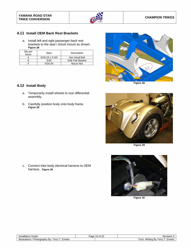
4.11 Install OEM Back Rest Brackets
a. Install left and right passenger back rest brackets to the seat / shock mount as shown. Figure 28
Qty per Assm Spec Description
4 5/16-24 x 2-3/4 Hex Head Bolt 8 5/16 SAE Flat Washer 4 5/16-24 NyLoc Nut
4.12 Install Body
a. Temporarily install wheels to rear differential assembly.
b. Carefully position body onto body frame. Figure 29
c. Connect trike body electrical harness to OEM harness. Figure 30
Figure 28
Figure 29
Figure 30
YAMAHA ROAD STAR TRIKE CONVERSION
CHAMPION TRIKES
Installation Guide Page 17 of 22 Revision 5 Illustrations / Photography By: Terry T. Emelio Tech. Writing By Terry T. Emelio
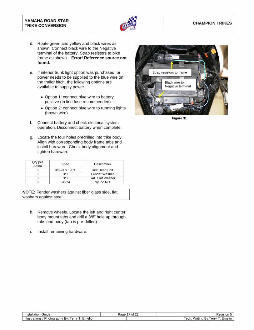
d. Route green and yellow and black wires as shown. Connect black wire to the Negative terminal of the battery. Strap resistors to bike frame as shown. Error! Reference source not found.
e. If interior trunk light option was purchased, or power needs to be supplied to the blue wire on the trailer hitch, the following options are available to supply power :
• Option 1: connect blue wire to battery positive (In line fuse recommended)
• Option 2: connect blue wire to running lights (brown wire)
f. Connect battery and check electrical system operation. Disconnect battery when complete.
g. Locate the four holes predrilled into trike body. Align with corresponding body frame tabs and install hardware. Check body alignment and tighten hardware.
Qty per Assm Spec Description
6 3/8-24 x 1-1/4 Hex Head Bolt 6 3/8 Fender Washer 6 3/8 SAE Flat Washer 6 3/8-24 NyLoc Nut
NOTE: Fender washers against fiber glass side, flat washers against steel.
h. Remove wheels. Locate the left and right center body mount tabs and drill a 3/8” hole up through tabs and body (tab is pre-drilled)
i. Install remaining hardware.
Black wire to Negative terminal
Strap resistors to frame
Figure 31
YAMAHA ROAD STAR TRIKE CONVERSION
CHAMPION TRIKES
Installation Guide Page 18 of 22 Revision 5 Illustrations / Photography By: Terry T. Emelio Tech. Writing By Terry T. Emelio
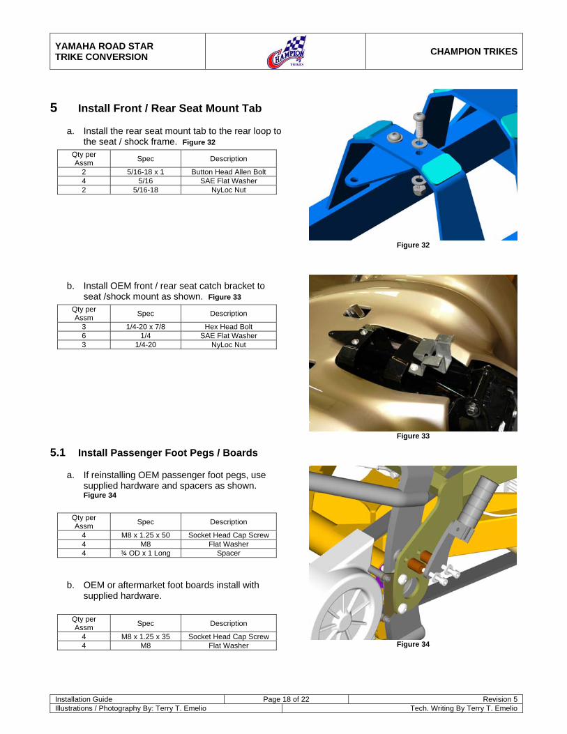
5 Install Front / Rear Seat Mount Tab
a. Install the rear seat mount tab to the rear loop to the seat / shock frame. Figure 32
Qty per Assm Spec Description
2 5/16-18 x 1 Button Head Allen Bolt 4 5/16 SAE Flat Washer 2 5/16-18 NyLoc Nut
b. Install OEM front / rear seat catch bracket to seat /shock mount as shown. Figure 33
Qty per Assm Spec Description
3 1/4-20 x 7/8 Hex Head Bolt 6 1/4 SAE Flat Washer 3 1/4-20 NyLoc Nut
5.1 Install Passenger Foot Pegs / Boards
a. If reinstalling OEM passenger foot pegs, use supplied hardware and spacers as shown. Figure 34
Qty per Assm Spec Description
4 M8 x 1.25 x 50 Socket Head Cap Screw 4 M8 Flat Washer 4 ¾ OD x 1 Long Spacer
b. OEM or aftermarket foot boards install with supplied hardware.
Qty per Assm Spec Description
4 M8 x 1.25 x 35 Socket Head Cap Screw 4 M8 Flat Washer
Figure 32
Figure 33
Figure 34
YAMAHA ROAD STAR TRIKE CONVERSION
CHAMPION TRIKES
Installation Guide Page 19 of 22 Revision 5 Illustrations / Photography By: Terry T. Emelio Tech. Writing By Terry T. Emelio
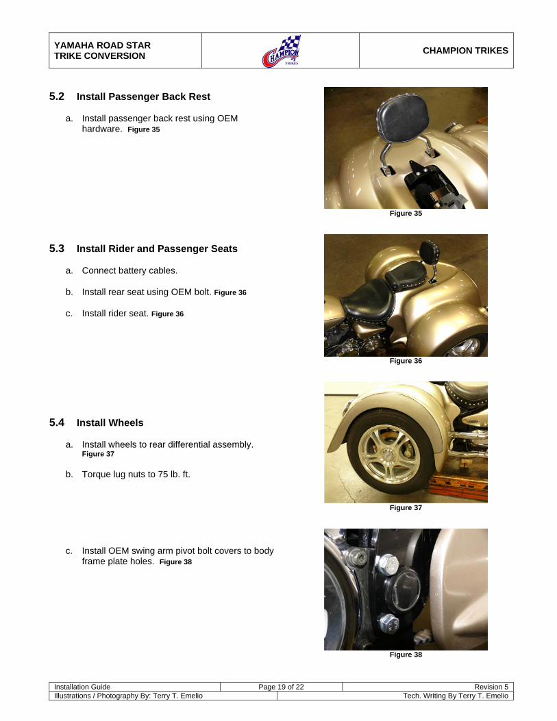
5.2 Install Passenger Back Rest
a. Install passenger back rest using OEM hardware. Figure 35
5.3 Install Rider and Passenger Seats
a. Connect battery cables.
b. Install rear seat using OEM bolt. Figure 36
c. Install rider seat. Figure 36
5.4 Install Wheels
a. Install wheels to rear differential assembly. Figure 37
b. Torque lug nuts to 75 lb. ft.
c. Install OEM swing arm pivot bolt covers to body frame plate holes. Figure 38
Figure 35
Figure 36
Figure 37
Figure 38

YAMAHA ROAD STAR TRIKE CONVERSION
CHAMPION TRIKES
Installation Guide Page 20 of 22 Revision 5 Illustrations / Photography By: Terry T. Emelio Tech. Writing By Terry T. Emelio
5.5 Install Trailer Tongue (Optional)
a. Install tongue to receiver on Trike Body Frame
b. Electrical connectors not supplied. Mounting tab for connector socket is located on hitch receiver.
c. Color code for wiring as follows: (Confirm wiring by testing)
Old Harness New Universal
Harness (From Mid 2007)
Running lights BLUE BROWN
Brake lights RED RED
Turn signal, right
GREEN GREEN
Turn signal, left YELLOW YELLOW
Accessory LIGHT BLUE BLUE
Ground BLACK BLACK

YAMAHA ROAD STAR TRIKE CONVERSION
CHAMPION TRIKES
Installation Guide Page 21 of 22 Revision 5 Illustrations / Photography By: Terry T. Emelio Tech. Writing By Terry T. Emelio
6 Part List
Part Illustration Description Part # Qty per Veh
Page
Drive Belt, Narrow 139
Tooth CH-F00-033 1 4.1
Swing Arm SU-K00-001 1 4.1
Rear Drive
Assm, Complete
DL-K00-001 1 4.1 - 4.3
Adjuster
Plate, L / RHS
SU-F00-005 2 4.2 - 4.3
Seat /
Shock Mount
SU-K00-003 1 4.4
Body Frame SU-K00-002 1 4.4 - 4.5
Residual Valve (3 lb) BR-E00-018 1 4.4
N/A Tee Fitting,
Rear Brakes
BR-EF0-002 1 4.4
N/A Brake Line, SS Braided
50” BR-F00-006 1 4.4
N/A Brake Line, SS Braided
20” BR-F00-001 2 4.4
Hanger Plate SU-K00-008 2 4.5
Part Illustration Description Part # Qty per Veh
Page
Support Strut SU-K00-007 2 4.6
Coil Over
Shock Absorber
SU-E00-001 2 4.7
Muffler Tip CH-K00-001 1 4.7
Exhaust Hanger
SU-K00-006 1 4.8
Exhaust Tube, Lower
CH-K00-004 1 4.9
Exhaust
Tube, Upper CH-K00-
002 1 4.9
Cover, Upper Exhaust
Tube
CH-K00-003 1 4.9
Cover, Lower Exhaust
Tube
CH-K00-005 1 4.9
Rear Seat Mounting Bracket
SU-K00-009 1 4.11
Spacer, Foot Rest Mount
CH-E00-015 4 4.11
YAMAHA ROAD STAR TRIKE CONVERSION
CHAMPION TRIKES
Installation Guide Page 22 of 22 Revision 5 Illustrations / Photography By: Terry T. Emelio Tech. Writing By Terry T. Emelio
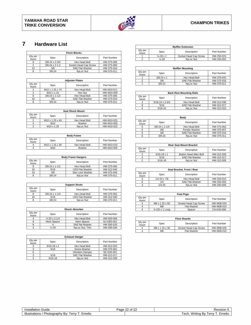
7 Hardware List
Pinch Blocks Qty per Assm Spec Description Part Number
6 3/8-24 x 2-3/4 Hex Head Bolt HW-375-056 2 3/8-24 x 2-1-2 Socket Head Cap Screw HW-375-060
14 3/8 SAE Flat Washer HW-375-016 8 3/8-24 NyLoc Nut HW-375-011
Adjuster Plates Qty per Assm Spec Description Part Number
2 M10 x 1.25 x 70 Hex Head Bolt HW-M10-011 2 M10 x 1.25 Hex Nut HW-M10-009 8 3/8-24 x 1-1/2 Hex Head Bolt HW-375-006
16 3/8 SAE Flat Washer HW-375-016 8 3/8-24 NyLoc Nut HW-375-011
Seat Shock Mount Qty per Assm Spec Description Part Number
2 M10 x 1.25 x 45 Hex Head Bolt HW-M10-025 4 M10 Washer HW-M10-005 2 M10 x 1.25 NyLoc Nut HW-M10-022
Body Frame Qty per Assm Spec Description Part Number
4 M10 x 1.25 x 30 Hex Head Bolt HW-M10-010 4 M10 Washer HW-M10-005
Body Frame Hangers Qty per Assm Spec Description Part Number
8 3/8-24 x 1-1/2 Hex Head Bolt HW-375-006 16 5/16 USS Flat Washer HW-312-040 16 3/8 Star Lock Washer HW-375-049 8 3/8-24 NyLoc Nut HW-375-011
Support Struts Qty per Assm Spec Description Part Number
8 3/8-24 x 1-1/4 Hex Head Bolt HW-375-052 16 5/16 USS Flat Washer HW-312-040 8 3/8-24 NyLoc Nut HW-375-011
Shock Absorber Qty per Assm Spec Description Part Number
4 ½-20 x 2-1/4 Hex Head Bolt HW-500-006 8 Heim Spacer Heim Spacer SU-DE0-001 8 ½ SAE flat Washer HW-500-020 4 ½-20 NyLoc Nut, Thin HW-500-034
Exhaust Hanger Qty per Assm Spec Description Part Number
3 5/16-18 x 2 Hex Head Bolt HW-312-023 3 5/16 Dome Washer HW-375-061 6 - Vibration Damper SE-G00-001 3 5/16 SAE Flat Washer HW-312-017 3 5/16-18 NyLoc Nut HW-312-009
Muffler Extension Qty per Assm Spec Description Part Number
1 ¼-28 x 1 Socket Head Cap Screw HW-250-024 2 ¼-28 NyLoc Nut HW-250-002
Muffler Mounting Qty per Assm Spec Description Part Number
1 3/8-24 x 1 Hex Head Bolt HW-375-042 2 3/8 SAE Flat Washer HW-375-016 1 3/8-24 NyLoc Nut HW-375-011
Back Rest Mounting Rails Qty per Assm Spec Description Part Number
4 5/16-24 x 2-3/4 Hex Head Bolt HW-312-036 8 5/16 SAE Flat Washer HW-312-017 4 5/16-24 NyLoc Nut HW-312-010
Body Qty per Assm Spec Description Part Number
6 3/8-24 x 1-1/4 Hex Head Bolt HW-375-052 6 3/8 Fender Washer HW-375-007 6 3/8 SAE Flat Washer HW-375-016 6 3/8-24 NyLoc Nut HW-375-011
Rear Seat Mount Bracket Qty per Assm Spec Description Part Number
2 5/16-18 x 1 Button Head Allen Bolt HW-312-026 4 5/16 SAE Flat Washer HW-312-017 2 5/16-18 NyLoc Nut HW-312-009
Seat Bracket, Front / Rear Qty per Assm Spec Description Part Number
3 1/4-20 x 7/8 Hex Head Bolt HW-250-010 6 1/4 SAE Flat Washer HW-250-004 3 1/4-20 NyLoc Nut HW-250-005
Foot Pegs Qty per Assm Spec Description Part Number
4 M8 x 1.25 x 50 Socket Head Cap Screw HW-M08-034 4 M8 Flat Washer HW-M08-010 4 ¾ OD x 1 Long Spacer CH-K00-006
Floor Boards Qty per Assm Spec Description Part Number
4 M8 x 1.25 x 35 Socket Head Cap Screw HW-M08-026 4 M8 Flat Washer HW-M08-010