Yamaha HS80M HS50M Service Manual
27
HAMAMATSU, JAPAN Copyright (c) Yamaha Corporation. All rights reserved. PDF Printed in Japan ’05.12 POWERED MONITOR SPEAKER HS80M SPECIFICATIONS (総合仕様) ..................................... 3 HS50M SPECIFICATIONS (総合仕様) ..................................... 4 DIMENSIONS (寸法図) ........................................................... 5 PANEL LAYOUT (パネルレイアウト) ...................................... 6 CIRCUIT BOARD LAYOUT (ユニットレイアウト) .................. 7 HS80M DISASSEMBLY PROCEDURE (分解手順) ................. 8 HS50M DISASSEMBLY PROCEDURE (分解手順) ............... 11 CIRCUIT BOARDS (シート基板図) ........................................ 14 HS80M INSPECTIONS (検査) ............................................... 15 HS50M INSPECTIONS (検査) ............................................... 16 BLOCK DIAGRAM (ブロックダイアグラム) OVERALL CIRCUIT DIAGRAM (総回路図) PARTS LIST ■ CONTENTS (目次) HS80M: 200510-47250 HS50M: 200510-26250 HS80M/HS50M 011806 PA SERVICE MANUAL このサービスマニュアルはエコパルプ� (ECF:無塩素系漂白パルプ)を使用しています。�
-
Upload
graeme-goodacre -
Category
Documents
-
view
647 -
download
66
Transcript of Yamaha HS80M HS50M Service Manual
HAMAMATSU, JAPANCopyright (c) Yamaha Corporation. All rights reserved. PDF Printed in Japan ’05.12
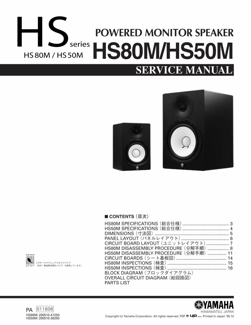
POWERED MONITOR SPEAKER
HS80M SPECIFICATIONS (総合仕様)..................................... 3HS50M SPECIFICATIONS (総合仕様)..................................... 4DIMENSIONS (寸法図)........................................................... 5PANEL LAYOUT (パネルレイアウト)...................................... 6CIRCUIT BOARD LAYOUT (ユニットレイアウト).................. 7HS80M DISASSEMBLY PROCEDURE (分解手順)................. 8HS50M DISASSEMBLY PROCEDURE (分解手順)............... 11CIRCUIT BOARDS (シート基板図)........................................ 14HS80M INSPECTIONS (検査)............................................... 15HS50M INSPECTIONS (検査)............................................... 16BLOCK DIAGRAM (ブロックダイアグラム)OVERALL CIRCUIT DIAGRAM (総回路図)PARTS LIST
� CONTENTS (目次)
HS80M: 200510-47250HS50M: 200510-26250
HS80M/HS50M
011806PA
SERVICE MANUAL
このサービスマニュアルはエコパルプ�(ECF:無塩素系漂白パルプ)を使用しています。�
HS80M/HS50M
2
IMPORTANT NOTICEThis manual has been provided for the use of authorized Yamaha Retailers and their service personnel. It has been assumedthat basic service procedures inherent to the industry, and more specifically Yamaha Products, are already known and under-stood by the users, and have therefore not been restated.
WARNING : Failure to follow appropriate service and safety procedures when servicing this product may result in per-sonal injury, destruction of expensive components and failure of the product to perform as specified. Forthese reasons, we advise all Yamaha product owners that all service required should be performed by anauthorized Yamaha Retailer or the appointed service representative.
IMPORTANT : This presentation or sale of this manual to any individual or firm does not constitute authorization, certifi-cation, recognition of any applicable technical capabilities, or establish a principal-agent relationship ofany form.
The data provided is believed to be accurate and applicable to the unit (s) indicated on the cover. The research engineering, andservice departments of Yamaha are continually str iving to improve Yamaha products. Modifications are, therefore, inevitableand changes in specification are subject to change without notice or obligation to retrofit. Should any discrepancy appear toexist, please contact the distributor’s Service Division.
WARNING : Static discharges can destroy expensive components. Discharge any static electricity your body may haveaccumulated by grounding yourself to the ground bus in the unit (heavy gauge black wires connect tothis bus).
IMPORTANT : Turn the unit OFF during disassembly and parts replacement. Recheck all work before you apply powerto the unit.
WARNING: CHEMICAL CONTENT NOTICE!The solder used in the production of this product contains LEAD. In addition, other electrical/electronic and/or plastic (Whereapplicable) components may also contain traces of chemicals found by the California Health and Welfare Agency (and possiblyother entities) to cause cancer and/or bir th defects or other reproductive harm.
DO NOT PLACE SOLDER, ELECTRICAL/ELECTRONIC OR PLASTIC COMPONENTS IN YOUR MOUTH FOR ANY REASON WHATSO EVER!
Avoid prolonged, unprotected contact between solder and your skin! When solder ing, do not inhale solder fumes or exposeeyes to solder/flux vapor!
If you come in contact with solder or components located inside the enclosure of this product, wash your hands before handlingfood.
� WARNINGComponents having special characteristics are marked and must bereplaced with parts having specification equal to those originally installed.
印の部品は、安全を維持するために重要な部品です。交換する場合は、安全のために必ず指定の部品をご使用ください。
WARNING: THIS APPARATUS MUST BE EARTHEDIMPORTANT
THE WIRES IN THIS MAINS LEAD ARE COLOURED INACCORDANCE WITH THE FOLLOWING CODE:
GREEN-AND-YELLOW : EARTHBLUE : NEUTRALBROWN : LIVE
As the colours of the wires in the mains lead of this apparatus maynot correspond with the coloured markings identifying the terminals inyour plug, proceed as follows:The wire which is coloured GREEN and YELLOW must beconnected to the terminal in the plug which is marked by the letter Eor by the safety earth symbol or coloured GREEN and YELLOW.The wire which is coloured BLUE must be connected to theterminal which is marked with the letter N or coloured BLACK.The wire which is coloured BROWN must be connected to the terminalwhich is marked with the letter L or coloured RED.
* This applies only to products distr ibuted by YAMAHA KEMBLEMUSIC (U.K.) LTD.
HS80M/HS50M
3
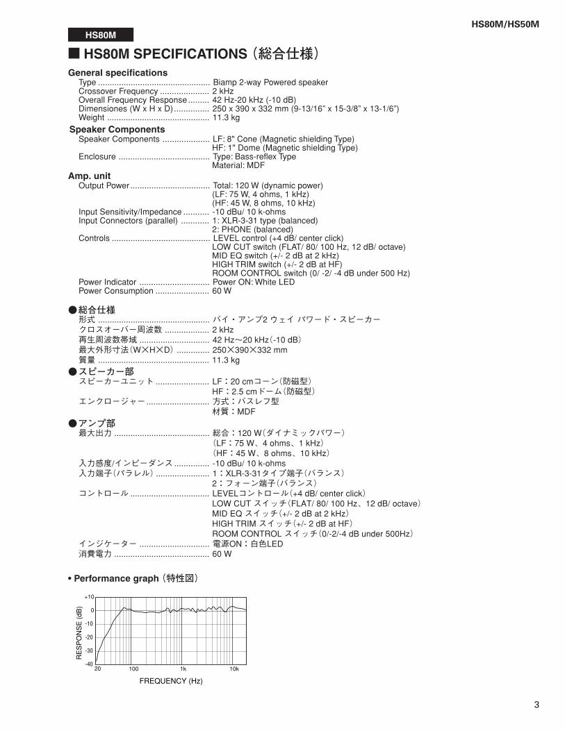
� HS80M SPECIFICATIONS (総合仕様)General specifications
Type ................................................ Biamp 2-way Powered speakerCrossover Frequency ..................... 2 kHzOverall Frequency Response ......... 42 Hz-20 kHz (-10 dB)Dimensiones (W x H x D) ............... 250 x 390 x 332 mm (9-13/16” x 15-3/8” x 13-1/6”)Weight ............................................ 11.3 kg
Speaker ComponentsSpeaker Components .................... LF: 8" Cone (Magnetic shielding Type)
HF: 1" Dome (Magnetic shielding Type)Enclosure ....................................... Type: Bass-reflex Type
Material: MDFAmp. unit
Output Power .................................. Total: 120 W (dynamic power)(LF: 75 W, 4 ohms, 1 kHz)(HF: 45 W, 8 ohms, 10 kHz)
Input Sensitivity/Impedance ........... -10 dBu/ 10 k-ohmsInput Connectors (parallel) ............ 1: XLR-3-31 type (balanced)
2: PHONE (balanced)Controls .......................................... LEVEL control (+4 dB/ center click)
LOW CUT switch (FLAT/ 80/ 100 Hz, 12 dB/ octave)MID EQ switch (+/- 2 dB at 2 kHz)HIGH TRIM switch (+/- 2 dB at HF)ROOM CONTROL switch (0/ -2/ -4 dB under 500 Hz)
Power Indicator .............................. Power ON: White LEDPower Consumption ....................... 60 W
●総合仕様形式 ................................................ バイ・アンプ2 ウェイ パワード・スピーカークロスオーバー周波数 ................... 2 kHz再生周波数帯域 .............................. 42 Hz~20 kHz(-10 dB)最大外形寸法(W×H×D).............. 250×390×332 mm質量 ................................................ 11.3 kg
●スピーカー部スピーカーユニット ....................... LF:20 cmコーン(防磁型)
HF:2.5 cmドーム(防磁型)エンクロージャー........................... 方式:バスレフ型
材質:MDF●アンプ部最大出力 ......................................... 総合:120 W(ダイナミックパワー)
(LF:75 W、4 ohms、1 kHz)(HF:45 W、8 ohms、10 kHz)
入力感度/インピーダンス............... -10 dBu/ 10 k-ohms入力端子(パラレル)....................... 1:XLR-3-31タイプ端子(バランス)
2:フォーン端子(バランス)コントロール .................................. LEVELコントロール(+4 dB/ center click)
LOW CUT スイッチ(FLAT/ 80/ 100 Hz、12 dB/ octave)MID EQ スイッチ(+/- 2 dB at 2 kHz)HIGH TRIM スイッチ(+/- 2 dB at HF)ROOM CONTROL スイッチ(0/-2/-4 dB under 500Hz)
インジケーター .............................. 電源ON:白色LED消費電力 ......................................... 60 W
• Performance graph (特性図)
10k1k10020
0
+10
RE
SP
ON
SE
(dB
)
-10
-20
-30
-40
FREQUENCY (Hz)
HS80M
HS80M/HS50M
4
10k1k10020
0
+10
RE
SP
ON
SE
(dB
)
-10
-20
-30
-40
FREQUENCY (Hz)
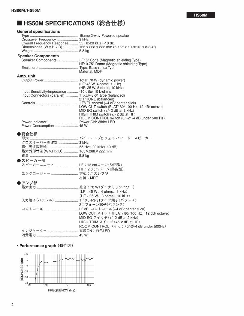
� HS50M SPECIFICATIONS (総合仕様)General specifications
Type ................................................ Biamp 2-way Powered speakerCrossover Frequency ..................... 3 kHzOverall Frequency Response......... 55 Hz-20 kHz (-10 dB)Dimensiones (W x H x D) ............... 165 x 268 x 222 mm (6-1/2” x 10-9/16” x 8-3/4”)Weight ............................................ 5.8 kg
Speaker ComponentsSpeaker Components .................... LF: 5" Cone (Magnetic shielding Type)
HF: 0.75" Dome (Magnetic shielding Type)Enclosure ....................................... Type: Bass-reflex Type
Material: MDFAmp. unit
Output Power .................................. Total: 70 W (dynamic power)(LF: 45 W, 4 ohms, 1 kHz)(HF: 25 W, 8 ohms, 10 kHz)
Input Sensitivity/Impedance ........... -10 dBu/ 10 k-ohmsInput Connectors (parallel) ............ 1: XLR-3-31 type (balanced)
2: PHONE (balanced)Controls .......................................... LEVEL control (+4 dB/ center click)
LOW CUT switch (FLAT/ 80/ 100 Hz, 12 dB/ octave)MID EQ switch (+/- 2 dB at 2 kHz)HIGH TRIM switch (+/- 2 dB at HF)ROOM CONTROL switch (0/ -2/ -4 dB under 500 Hz)
Power Indicator .............................. Power ON: White LEDPower Consumption ....................... 45 W
●総合仕様形式 ................................................ バイ・アンプ2 ウェイ パワード・スピーカークロスオーバー周波数 ................... 3 kHz再生周波数帯域 .............................. 55 Hz~20 kHz(-10 dB)最大外形寸法(W×H×D).............. 165×268×222 mm質量 ................................................ 5.8 kg
●スピーカー部スピーカーユニット ....................... LF:13 cmコーン(防磁型)
HF:2.0 cmドーム(防磁型)エンクロージャー........................... 方式:バスレフ型
材質:MDF●アンプ部最大出力 ......................................... 総合:70 W(ダイナミックパワー)
(LF:45 W、4 ohms、1 kHz)(HF:25 W、8 ohms、10 kHz)
入力端子(パラレル)....................... 1:XLR-3-31タイプ端子(バランス)2:フォーン端子(バランス)
コントロール .................................. LEVELコントロール(+4 dB/ center click)LOW CUT スイッチ(FLAT/ 80/ 100 Hz、12 dB/ octave)MID EQ スイッチ(+/- 2 dB at 2 kHz)HIGH TRIM スイッチ(+/- 2 dB at HF)ROOM CONTROL スイッチ(0/-2/-4 dB under 500Hz)
インジケーター .............................. 電源ON:白色LED消費電力 ......................................... 45 W
• Performance graph (特性図)
HS50M
HS80M/HS50M
5
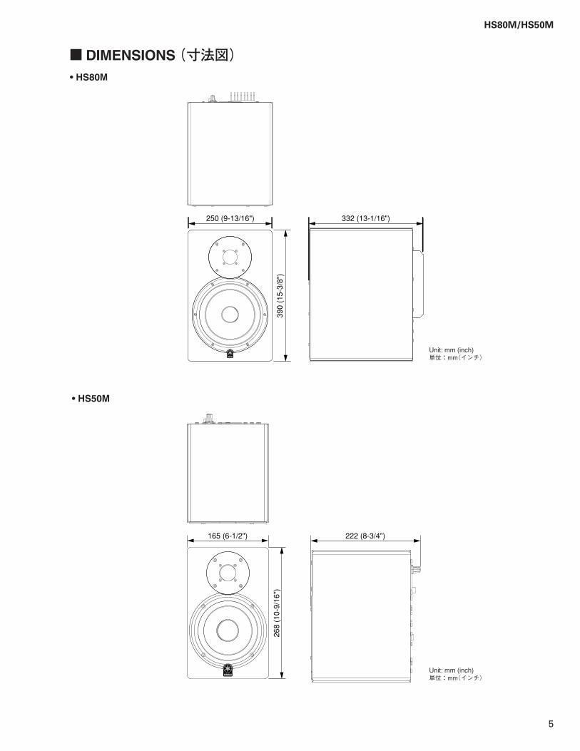
� DIMENSIONS (寸法図)
250 (9-13/16") 332 (13-1/16")
390
(15-
3/8"
)
165 (6-1/2") 222 (8-3/4")
268
(10-
9/16
")
• HS80M
• HS50M
Unit: mm (inch)単位:mm(インチ)
Unit: mm (inch)単位:mm(インチ)
HS80M/HS50M
6
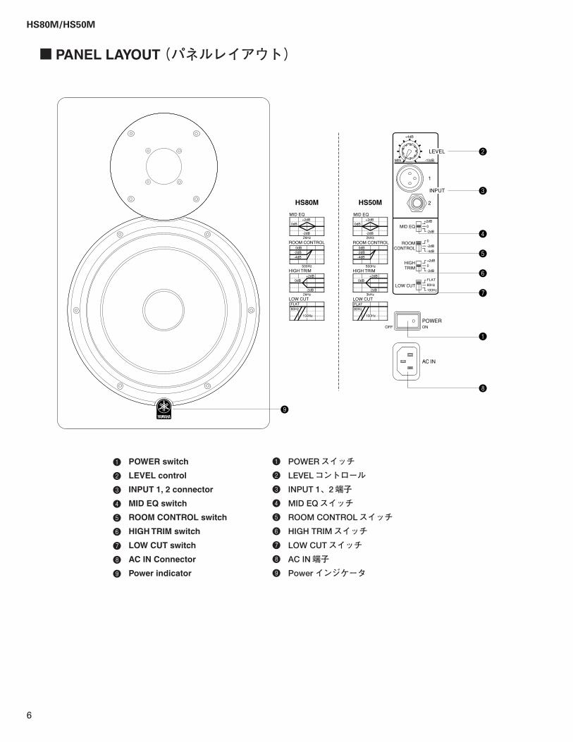
� PANEL LAYOUT (パネルレイアウト)
OFF
INPUT
LEVEL
POWERON
AC IN
HS50MHS80M
1
2
3
4
5
6
7
8
ROOM CONTROL
HIGH TRIM
+2dB
+2dB
0dB
0dB
-2dB
-2dB
0dB-2dB-4dB
MID EQ
LOW CUT
2kHz
3kHz
500Hz
100Hz
80Hz
+2dB
+2dB
0dB
0dB
-2dB
-2dB
0dB-2dB-4dB
2kHz
2kHz
500Hz
100Hz
FLAT80Hz
ROOM CONTROL
HIGH TRIM
MID EQ
LOW CUTFLAT
MID EQ
ROOMCONTROL
HIGHTRIM
LOW CUT
+2dB
0
-2dB
0
-2dB
-4dB
+2dB
0
-2dB
FLAT
80Hz
100Hz
-10dB
+4dB
1
2
MIN
9
1 POWER switch
2 LEVEL control
3 INPUT 1, 2 connector
4 MID EQ switch
5 ROOM CONTROL switch
6 HIGH TRIM switch
7 LOW CUT switch
8 AC IN Connector
9 Power indicator
1 POWERスイッチ2 LEVELコントロール3 INPUT 1、2端子4 MID EQスイッチ5 ROOM CONTROLスイッチ6 HIGH TRIMスイッチ7 LOW CUTスイッチ8 AC IN端子9 Power インジケータ
HS80M/HS50M
7
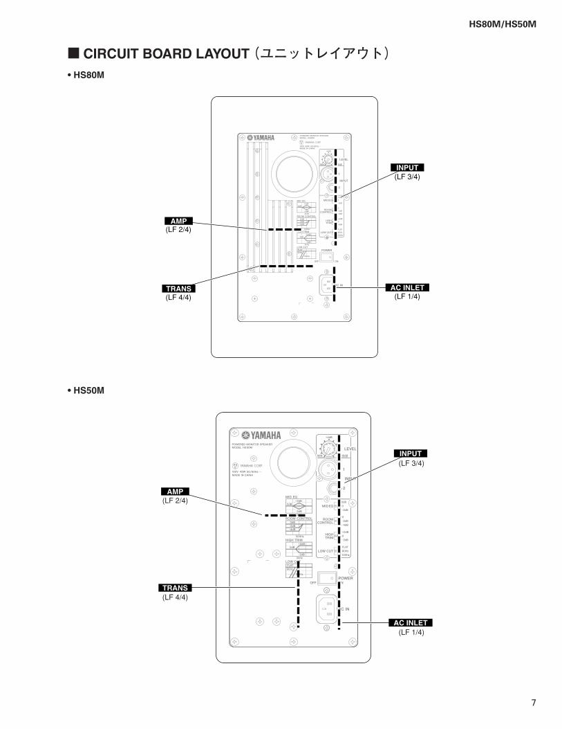
� CIRCUIT BOARD LAYOUT (ユニットレイアウト)• HS80M
• HS50M
INPUT
AC INLETTRANS
AMP(LF 2/4)
(LF 3/4)
(LF 1/4)(LF 4/4)
INPUT
AC INLET
TRANS
AMP(LF 2/4)
(LF 3/4)
(LF 1/4)
(LF 4/4)
HS80M/HS50M
8
� HS80M DISASSEMBLY PROCEDURE (分解手順)
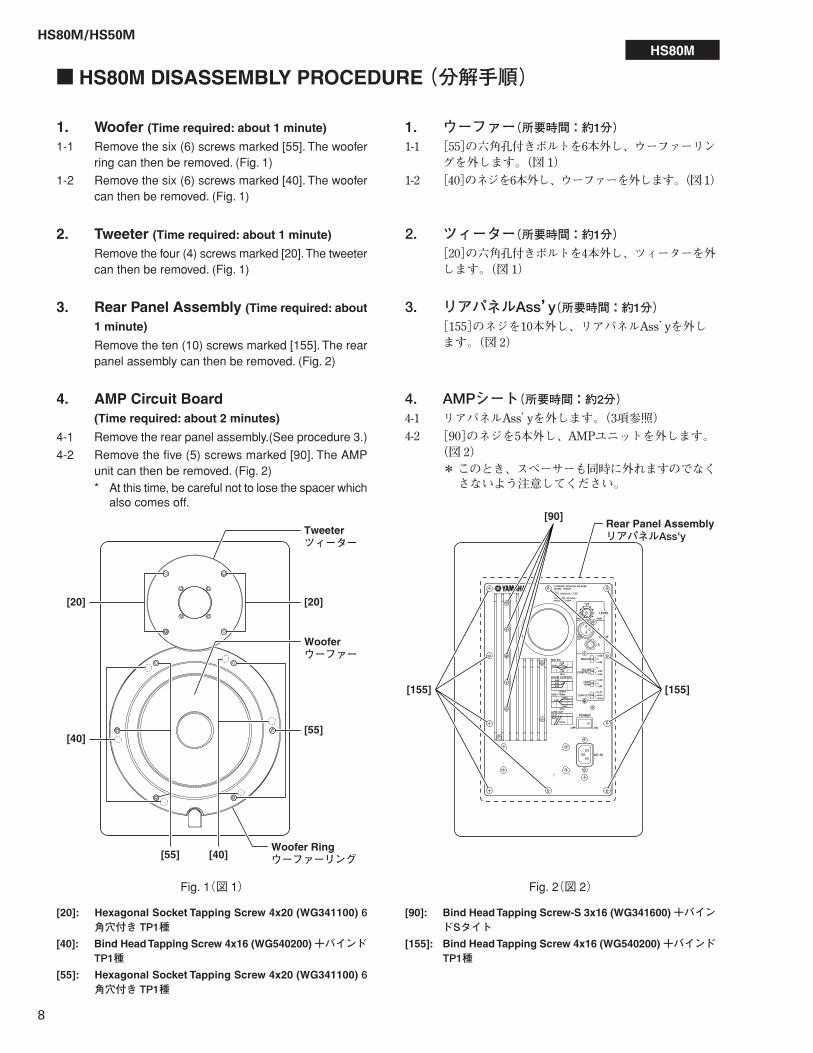
1. Woofer (Time required: about 1 minute)
1-1 Remove the six (6) screws marked [55]. The wooferring can then be removed. (Fig. 1)
1-2 Remove the six (6) screws marked [40]. The woofercan then be removed. (Fig. 1)
2. Tweeter (Time required: about 1 minute)
Remove the four (4) screws marked [20]. The tweetercan then be removed. (Fig. 1)
[20]: Hexagonal Socket Tapping Screw 4x20 (WG341100) 6角穴付き TP1種
[40]: Bind Head Tapping Screw 4x16 (WG540200) +バインドTP1種
[55]: Hexagonal Socket Tapping Screw 4x20 (WG341100) 6角穴付き TP1種
Fig. 1(図 1)
3. Rear Panel Assembly (Time required: about
1 minute)
Remove the ten (10) screws marked [155]. The rearpanel assembly can then be removed. (Fig. 2)
4. AMP Circuit Board(Time required: about 2 minutes)
4-1 Remove the rear panel assembly.(See procedure 3.)
4-2 Remove the five (5) screws marked [90]. The AMPunit can then be removed. (Fig. 2)* At this time, be careful not to lose the spacer which
also comes off.
Fig. 2(図 2)
[90]: Bind Head Tapping Screw-S 3x16 (WG341600) +バインドSタイト
[155]: Bind Head Tapping Screw 4x16 (WG540200) +バインドTP1種
1. ウーファー(所要時間:約1分)1-1 [55]の六角孔付きボルトを6本外し、ウーファーリン
グを外します。(図 1)1-2 [40]のネジを6本外し、ウーファーを外します。(図 1)
2. ツィーター(所要時間:約1分)[20]の六角孔付きボルトを4本外し、ツィーターを外します。(図 1)
4. AMPシート(所要時間:約2分)4-1 リアパネルAss’yを外します。(3項参照)4-2 [90]のネジを5本外し、AMPユニットを外します。
(図 2)*このとき、スペーサーも同時に外れますのでなくさないよう注意してください。
3. リアパネルAss’y(所要時間:約1分)[155]のネジを10本外し、リアパネルAss’yを外します。(図 2)
HS80M
[20] [20]
[40]Woofer Ringウーファーリング�[55]
[55][40]
Wooferウーファー�
Tweeterツィーター�
[90]
[155][155]
Rear Panel AssemblyリアパネルAss'y
HS80M/HS50M
9
HS80M
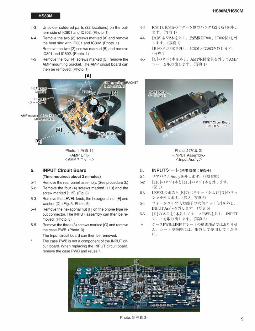
5. INPUT Circuit Board(Time required: about 3 minutes)
5-1 Remove the rear panel assembly. (See procedure 3.)
5-2 Remove the four (4) screws marked [110] and thescrew marked [115]. (Fig. 3)
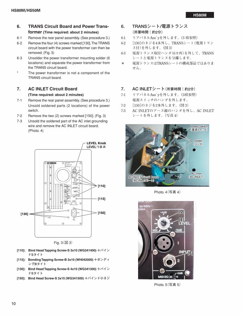
5-3 Remove the LEVEL knob, the hexagonal nut [E] andwasher [D]. (Fig. 3, Photo. 5)
5-4 Remove the hexagonal nut [F] on the phone type in-put connector. The INPUT assembly can then be re-moved. (Photo. 5)
5-5 Remove the three (3) screws marked [G] and removethe case PWB. (Photo. 3)
The Input circuit board can then be removed.
* The case PWB is not a component of the INPUT cir-cuit board. When replacing the INPUT circuit board,remove the case PWB and reuse it.
5. INPUTシート(所要時間:約3分)5-1 リアパネルAss’yを外します。(3項参照)5-2 [110]のネジ4本と[115]のネジ1本を外します。
(図 3)5-3 LEVELつまみと[E]の六角ナットおよび[D]のワッ
シャを外します。(図 3、写真 5)5-4 フォーンタイプ入力端子の六角ナット[F]を外し、
INPUT Ass’yを外します。(写真 5)5-5 [G]のネジを3本外してケースPWBを外し、INPUT
シートを取り出します。(写真 3)* ケースPWBはINPUTシートの構成部品ではありませ
ん。シート交換時には、取外して使用してください。
4-3 IC801とIC802のパターン側のハンダ(22カ所)を外します。(写真 1)
4-4 [A]のネジ2本を外し、放熱板(IC801、IC802付)を外します。(写真 1)[B]のネジ2本を外し、IC801とIC802を外します。(写真 1)
4-5 [C]のネジ4本を外し、AMP取付金具を外してAMPシートを取り出します。(写真 1)
[A]
[C][C]
[C][C]
[B][B]
IC801IC801
IC802IC802
AMP mounting BRACKET(AMP取付金具)�AMP mounting BRACKET(AMP取付金具)�
AMP mounting BRACKET(AMP取付金具)�
AMP mounting BRACKET(AMP取付金具)�
AMP circuit board(AMPシート)�AMP circuit board(AMPシート)�
SPACER(スペーサー)�
SPACER(スペーサー)�
HEAT SINK(放熱板)�
HEAT SINK(放熱板)�
INPUT Circuit Board(INPUTシート)�
INPUT Circuit Board(INPUTシート)�
CASE PWB(ケース PWB)�
CASE PWB(ケース PWB)�
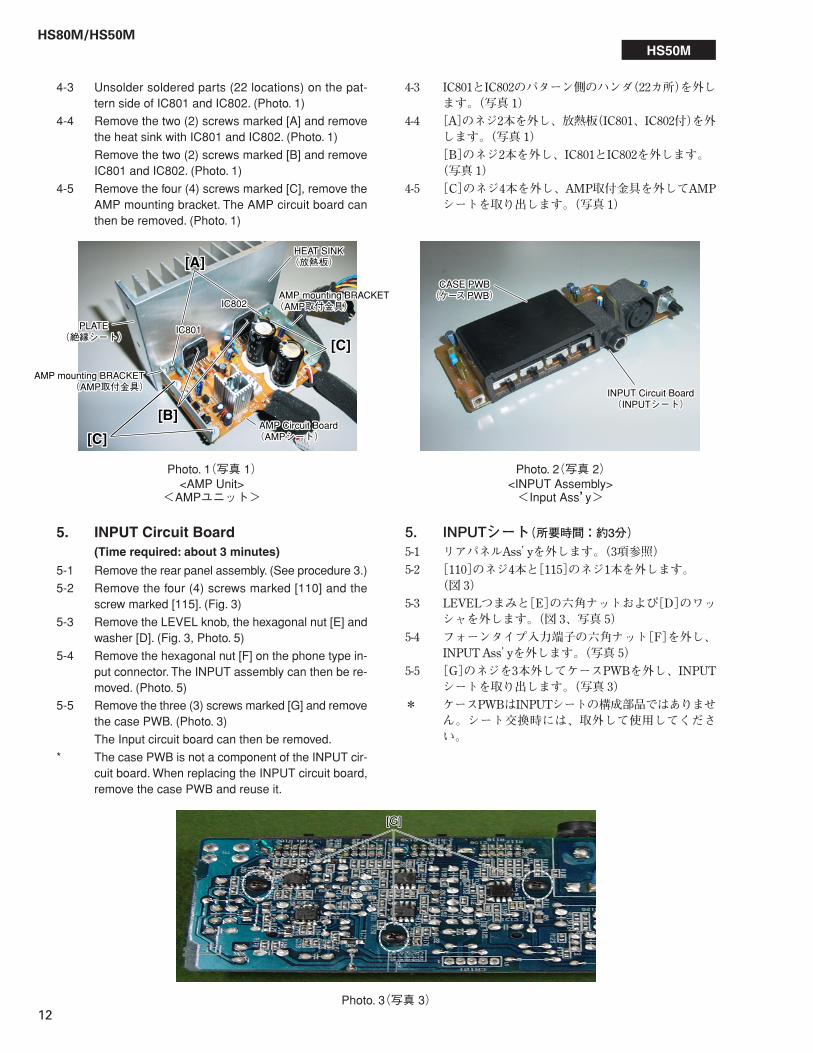
Photo. 1(写真 1)<AMP Unit>
<AMPユニット>
Photo. 2(写真 2)<INPUT Assembly><Input Ass’y>
4-3 Unsolder soldered parts (22 locations) on the pat-tern side of IC801 and IC802. (Photo. 1)
4-4 Remove the two (2) screws marked [A] and removethe heat sink with IC801 and IC802. (Photo. 1)
Remove the two (2) screws marked [B] and removeIC801 and IC802. (Photo. 1)
4-5 Remove the four (4) screws marked [C], remove theAMP mounting bracket. The AMP circuit board canthen be removed. (Photo. 1)
Photo. 3(写真 3)
[G][G]
HS80M/HS50M
10
6. TRANS Circuit Board and Power Trans-former (Time required: about 2 minutes)
6-1 Remove the rear panel assembly. (See procedure 3.)
6-2 Remove the four (4) screws marked [130]. The TRANScircuit board with the power transformer can then beremoved. (Fig. 3)
6-3 Unsolder the power transformer mounting solder (6locations) and separate the power transformer fromthe TRANS circuit board.
* The power transformer is not a component of theTRANS circuit board.
7. AC INLET Circuit Board(Time required: about 2 minutes)
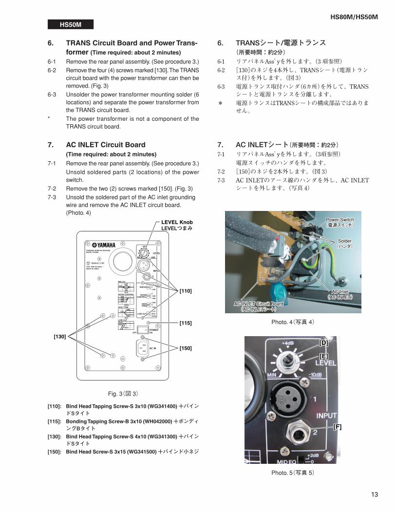
7-1 Remove the rear panel assembly. (See procedure 3.)
Unsold soldered parts (2 locations) of the powerswitch.
7-2 Remove the two (2) screws marked [150]. (Fig. 3)
7-3 Unsold the soldered part of the AC inlet groundingwire and remove the AC INLET circuit board.(Photo. 4)
[110]: Bind Head Tapping Screw-S 3x10 (WG341400) +バインドSタイト
[115]: Bonding Tapping Screw-B 3x10 (WH042000) +ボンディングBタイト
[130]: Bind Head Tapping Screw-S 4x10 (WG341300) +バインドSタイト
[150]: Bind Head Screw-S 3x15 (WG341500) +バインド小ネジ
6. TRANSシート/電源トランス(所要時間:約2分)
6-1 リアパネルAss’yを外します。(3 項参照)6-2 [130]のネジを4本外し、TRANSシート(電源トラン
ス付)を外します。(図 3)6-3 電源トランス取付ハンダ(6カ所)を外して、TRANS
シートと電源トランスを分離します。* 電源トランスはTRANSシートの構成部品ではありま
せん。
7. AC INLETシート(所要時間:約2分)7-1 リアパネルAss’yを外します。(3項参照)
電源スイッチのハンダを外します。7-2 [150]のネジを2本外します。(図 3)7-3 AC INLETのアース線のハンダを外し、AC INLET
シートを外します。(写真 4)
[110]
[115]
[130] [150]
LEVEL KnobLEVELつまみ�
Fig. 3(図 3)
HS80M
Solder(ハンダ)�
Solder(ハンダ)�
AC Inlet(AC INLET)�
AC Inlet(AC INLET)�AC INLET Circuit Board
(AC INLETシート)�AC INLET Circuit Board(AC INLETシート)�
Power Switch(電源スイッチ)�
Power Switch(電源スイッチ)�
[D][D]
[E][E]
[F][F]
Photo. 4(写真 4)
Photo. 5(写真 5)
HS80M/HS50M
11
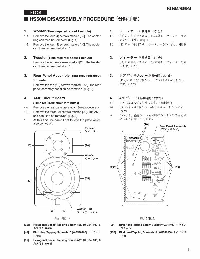
1. Woofer (Time required: about 1 minute)
1-1 Remove the four (4) screws marked [55]. The wooferring can then be removed. (Fig. 1)
1-2 Remove the four (4) screws marked [40]. The woofercan then be removed. (Fig. 1)
2. Tweeter (Time required: about 1 minute)
Remove the four (4) screws marked [20]. The tweetercan then be removed. (Fig. 1)
[20]: Hexagonal Socket Tapping Screw 4x20 (WG341100) 6角穴付き TP1種
[40]: Bind Head Tapping Screw 4x16 (WG540200) +バインドTP1種
[55]: Hexagonal Socket Tapping Screw 4x20 (WG341100) 6角穴付き TP1種
Fig. 1(図 1)
3. Rear Panel Assembly (Time required: about
1 minute)
Remove the ten (10) screws marked [155]. The rearpanel assembly can then be removed. (Fig. 2)
4. AMP Circuit Board(Time required: about 2 minutes)
4-1 Remove the rear panel assembly. (See procedure 3.)
4-2 Remove the three (3) screws marked [90]. The AMPunit can then be removed. (Fig. 2)
* At this time, be careful not to lose the plate whichalso comes off.
Fig. 2(図 2)
[90]: Bind Head Tapping Screw-S 3x10 (WG341400) +バインドSタイト
[155]: Bind Head Tapping Screw 4x16 (WG540200) +バインドTP1種
1. ウーファー(所要時間:約1分)1-1 [55]の六角孔付きボルトを4本外し、ウーファーリン
グを外します。(Fig. 1)1-2 [40]のネジを4本外し、ウーファーを外します。(図 1)
2. ツィーター(所要時間:約1分)[20]の六角孔付きボルトを4本外し、ツィーターを外します。(図 1)
4. AMPシート(所要時間:約2分)4-1 リアパネルAss’yを外します。(3項参照)4-2 [90]のネジを3本外し、AMPユニットを外します。
(図 2)* このとき、絶縁シートも同時に外れますのでなくさ
ないよう注意してください。
3. リアパネルAss’y(所要時間:約1分)[155]のネジを10本外し、リアパネルAss’yを外します。(図 2)
[20] [20]
[40]Woofer Ringウーファーリング�[55]
[55][40]
Wooferウーファー�
Tweeterツィーター�
[90]
[155][155]
Rear Panel AssemblyリアパネルAss'y
� HS50M DISASSEMBLY PROCEDURE (分解手順)HS50M
HS80M/HS50M
12
5. INPUT Circuit Board(Time required: about 3 minutes)
5-1 Remove the rear panel assembly. (See procedure 3.)
5-2 Remove the four (4) screws marked [110] and thescrew marked [115]. (Fig. 3)
5-3 Remove the LEVEL knob, the hexagonal nut [E] andwasher [D]. (Fig. 3, Photo. 5)
5-4 Remove the hexagonal nut [F] on the phone type in-put connector. The INPUT assembly can then be re-moved. (Photo. 5)
5-5 Remove the three (3) screws marked [G] and removethe case PWB. (Photo. 3)
The Input circuit board can then be removed.
* The case PWB is not a component of the INPUT cir-cuit board. When replacing the INPUT circuit board,remove the case PWB and reuse it.
5. INPUTシート(所要時間:約3分)5-1 リアパネルAss’yを外します。(3項参照)5-2 [110]のネジ4本と[115]のネジ1本を外します。
(図 3)5-3 LEVELつまみと[E]の六角ナットおよび[D]のワッ
シャを外します。(図 3、写真 5)5-4 フォーンタイプ入力端子の六角ナット[F]を外し、
INPUT Ass’yを外します。(写真 5)5-5 [G]のネジを3本外してケースPWBを外し、INPUT
シートを取り出します。(写真 3)* ケースPWBはINPUTシートの構成部品ではありませ
ん。シート交換時には、取外して使用してください。
HS50M
4-3 IC801とIC802のパターン側のハンダ(22カ所)を外します。(写真 1)
4-4 [A]のネジ2本を外し、放熱板(IC801、IC802付)を外します。(写真 1)[B]のネジ2本を外し、IC801とIC802を外します。(写真 1)
4-5 [C]のネジ4本を外し、AMP取付金具を外してAMPシートを取り出します。(写真 1)
[A][A]
[C][C]
[C][C]
[B][B]
IC801IC801
IC802IC802AMP mounting BRACKET(AMP取付金具)�AMP mounting BRACKET(AMP取付金具)�
AMP mounting BRACKET(AMP取付金具)�
AMP mounting BRACKET(AMP取付金具)�
HEAT SINK(放熱板)�HEAT SINK(放熱板)�
AMP Circuit Board(AMPシート)�AMP Circuit Board(AMPシート)�
PLATE(絶縁シート)�
PLATE(絶縁シート)�
INPUT Circuit Board(INPUTシート)�
INPUT Circuit Board(INPUTシート)�
CASE PWB(ケース PWB)�
CASE PWB(ケース PWB)�
Photo. 1(写真 1)<AMP Unit>
<AMPユニット>
Photo. 2(写真 2)<INPUT Assembly><Input Ass’y>
4-3 Unsolder soldered parts (22 locations) on the pat-tern side of IC801 and IC802. (Photo. 1)
4-4 Remove the two (2) screws marked [A] and removethe heat sink with IC801 and IC802. (Photo. 1)
Remove the two (2) screws marked [B] and removeIC801 and IC802. (Photo. 1)
4-5 Remove the four (4) screws marked [C], remove theAMP mounting bracket. The AMP circuit board canthen be removed. (Photo. 1)
Photo. 3(写真 3)
[G][G]
HS80M/HS50M
13
Fig. 3(図 3)
HS50M
[110]
[130]
[150]
[115]
LEVEL KnobLEVELつまみ�
Solder(ハンダ)�
Solder(ハンダ)�
AC Inlet(AC INLET)�
AC Inlet(AC INLET)�
Power Switch(電源スイッチ)�
Power Switch(電源スイッチ)�
AC INLET Circuit Board(AC INLETシート)�
AC INLET Circuit Board(AC INLETシート)�
[D][D]
[E][E]
[F][F]
Photo. 4(写真 4)
Photo. 5(写真 5)
6. TRANSシート/電源トランス(所要時間:約2分)
6-1 リアパネルAss’yを外します。(3 項参照)6-2 [130]のネジを4本外し、TRANSシート(電源トラン
ス付)を外します。(図 3)6-3 電源トランス取付ハンダ(6カ所)を外して、TRANS
シートと電源トランスを分離します。* 電源トランスはTRANSシートの構成部品ではありま
せん。
7. AC INLETシート(所要時間:約2分)7-1 リアパネルAss’yを外します。(3項参照)
電源スイッチのハンダを外します。7-2 [150]のネジを2本外します。(図 3)7-3 AC INLETのアース線のハンダを外し、AC INLET
シートを外します。(写真 4)
6. TRANS Circuit Board and Power Trans-former (Time required: about 2 minutes)
6-1 Remove the rear panel assembly. (See procedure 3.)
6-2 Remove the four (4) screws marked [130]. The TRANScircuit board with the power transformer can then beremoved. (Fig. 3)
6-3 Unsolder the power transformer mounting solder (6locations) and separate the power transformer fromthe TRANS circuit board.
* The power transformer is not a component of theTRANS circuit board.
7. AC INLET Circuit Board(Time required: about 2 minutes)
7-1 Remove the rear panel assembly. (See procedure 3.)
Unsold soldered parts (2 locations) of the powerswitch.
7-2 Remove the two (2) screws marked [150]. (Fig. 3)
7-3 Unsold the soldered part of the AC inlet groundingwire and remove the AC INLET circuit board.(Photo. 4)
[110]: Bind Head Tapping Screw-S 3x10 (WG341400) +バインドSタイト
[115]: Bonding Tapping Screw-B 3x10 (WH042000) +ボンディングBタイト
[130]: Bind Head Tapping Screw-S 4x10 (WG341300) +バインドSタイト
[150]: Bind Head Screw-S 3x15 (WG341500) +バインド小ネジ
HS80M/HS50M
14
MIN
-10dB1
2M
ID E
QR
OO
MC
ON
TR
OL
HIG
HT
RIM
LOW
CU
T
LE
VE
LIN
PU
T
+2dB
0
-2dB
+2dB
0
-2dB
0
-2dB
-4dB
Component side (部品側)�
Component side (部品側)�
Component side (部品側)�
Component side (部品側)�
TRANS
INPUT
AMP
AC INLET
CN803: to TRANS-CN801
CN804: to AMP-CN805
CN801: toAC INLET-CN803
CN603:to POWER
INDICATOR-CN604
POWERINDICATOR
CN805: to TRANS-CN804
CN602: to INPUT-CB101
CN601: to WOOFER and TWEETER
CN802: to AC IN
CB
101: to A
MP
-CN
602
FLAT
80Hz
100Hz
TWEETER
WOOFER
AC IN
POWERSWITCH
* 1 * 1
* 2 * 3
CN604: to AMP-CN603
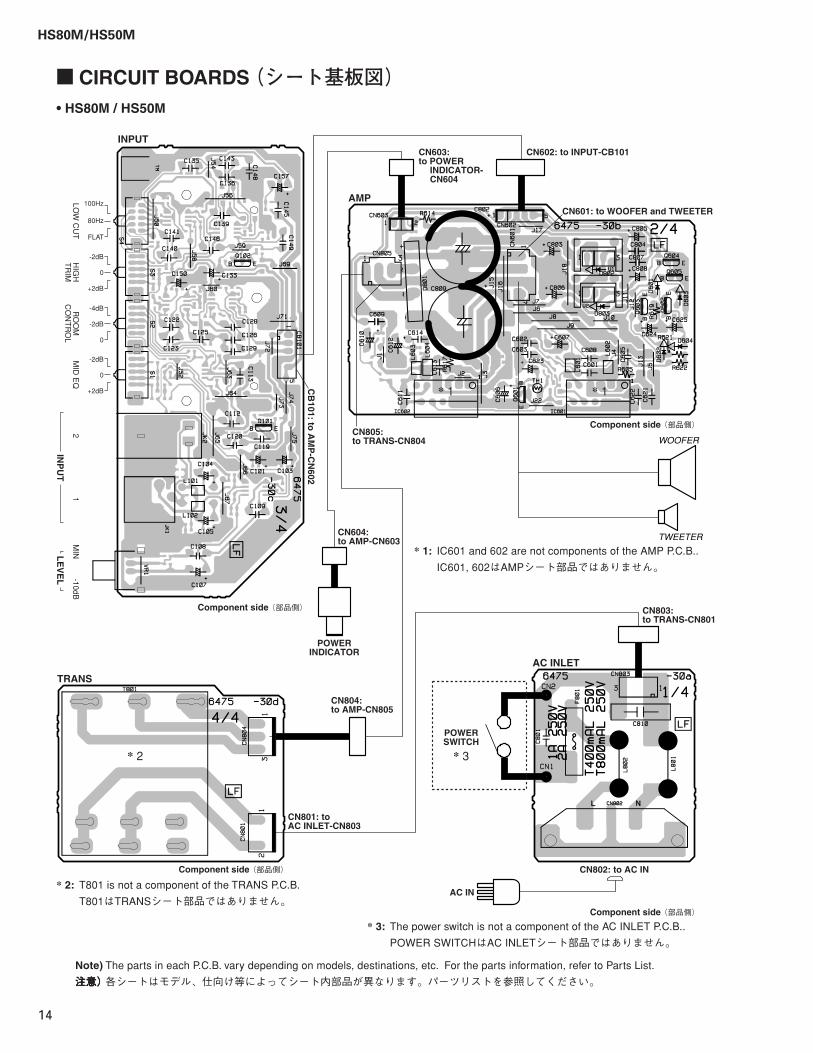
� CIRCUIT BOARDS (シート基板図)• HS80M / HS50M
* 1: IC601 and 602 are not components of the AMP P.C.B..
IC601, 602はAMPシート部品ではありません。
* 3: The power switch is not a component of the AC INLET P.C.B..
POWER SWITCHはAC INLETシート部品ではありません。
* 2: T801 is not a component of the TRANS P.C.B.
T801はTRANSシート部品ではありません。
Note) The parts in each P.C.B. vary depending on models, destinations, etc. For the parts information, refer to Parts List.
注意)注意)注意)注意)注意) 各シートはモデル、仕向け等によってシート内部品が異なります。パーツリストを参照してください。
HS80M/HS50M
15
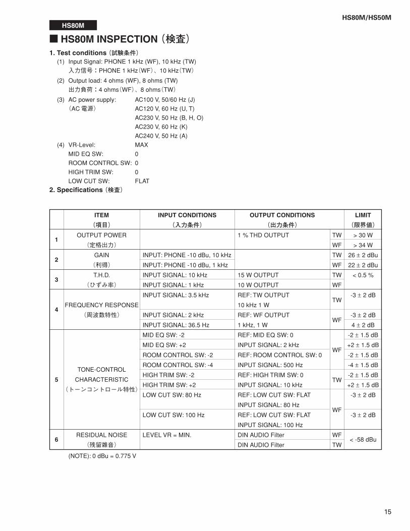
1. Test conditions (試験条件)(1) Input Signal: PHONE 1 kHz (WF), 10 kHz (TW)
入力信号:PHONE 1 kHz(WF)、10 kHz(TW)
(2) Output load: 4 ohms (WF), 8 ohms (TW)
出力負荷:4 ohms(WF)、8 ohms(TW)
(3) AC power supply: AC100 V, 50/60 Hz (J)
(AC電源) AC120 V, 60 Hz (U, T)
AC230 V, 50 Hz (B, H, O)
AC230 V, 60 Hz (K)
AC240 V, 50 Hz (A)
(4) VR-Level: MAX
MID EQ SW: 0
ROOM CONTROL SW: 0
HIGH TRIM SW: 0
LOW CUT SW: FLAT
2. Specifications (検査)
(NOTE): 0 dBu = 0.775 V
HS80M
� HS80M INSPECTION (検査)
LIMIT
(限界値)> 30 W
> 34 W
26 ± 2 dBu
22 ± 2 dBu
< 0.5 %
-3 ± 2 dB
-3 ± 2 dB
4 ± 2 dB
-2 ± 1.5 dB
+2 ± 1.5 dB
-2 ± 1.5 dB
-4 ± 1.5 dB
-2 ± 1.5 dB
+2 ± 1.5 dB
-3 ± 2 dB
-3 ± 2 dB
< -58 dBu
1
2
3
4
5
6
ITEM
(項目)OUTPUT POWER
(定格出力)
GAIN
(利得)
T.H.D.
(ひずみ率)
FREQUENCY RESPONSE
(周波数特性)
TONE-CONTROL
CHARACTERISTIC
(トーンコントロール特性)
RESIDUAL NOISE
(残留雑音)
INPUT CONDITIONS
(入力条件)
INPUT: PHONE -10 dBu, 10 kHz
INPUT: PHONE -10 dBu, 1 kHz
INPUT SIGNAL: 10 kHz
INPUT SIGNAL: 1 kHz
INPUT SIGNAL: 3.5 kHz
INPUT SIGNAL: 2 kHz
INPUT SIGNAL: 36.5 Hz
MID EQ SW: -2
MID EQ SW: +2
ROOM CONTROL SW: -2
ROOM CONTROL SW: -4
HIGH TRIM SW: -2
HIGH TRIM SW: +2
LOW CUT SW: 80 Hz
LOW CUT SW: 100 Hz
LEVEL VR = MIN.
OUTPUT CONDITIONS
(出力条件)1 % THD OUTPUT
15 W OUTPUT
10 W OUTPUT
REF: TW OUTPUT
10 kHz 1 W
REF: WF OUTPUT
1 kHz, 1 W
REF: MID EQ SW: 0
INPUT SIGNAL: 2 kHz
REF: ROOM CONTROL SW: 0
INPUT SIGNAL: 500 Hz
REF: HIGH TRIM SW: 0
INPUT SIGNAL: 10 kHz
REF: LOW CUT SW: FLAT
INPUT SIGNAL: 80 Hz
REF: LOW CUT SW: FLAT
INPUT SIGNAL: 100 Hz
DIN AUDIO Filter
DIN AUDIO Filter
TW
WF
TW
WF
TW
WF
TW
WF
WF
TW
WF
WF
TW
HS80M/HS50M
16
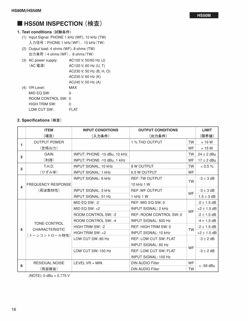
1. Test conditions (試験条件)(1) Input Signal: PHONE 1 kHz (WF), 10 kHz (TW)
入力信号:PHONE 1 kHz(WF)、10 kHz(TW)
(2) Output load: 4 ohms (WF), 8 ohms (TW)
出力負荷:4 ohms(WF)、8 ohms(TW)
(3) AC power supply: AC100 V, 50/60 Hz (J)
(AC電源) AC120 V, 60 Hz (U, T)
AC230 V, 50 Hz (B, H, O)
AC230 V, 60 Hz (K)
AC240 V, 50 Hz (A)
(4) VR-Level: MAX
MID EQ SW: 0
ROOM CONTROL SW: 0
HIGH TRIM SW: 0
LOW CUT SW: FLAT
2. Specifications (検査)
(NOTE): 0 dBu = 0.775 V
HS50M
� HS50M INSPECTION (検査)
LIMIT
(限界値)> 16 W
> 15 W
24 ± 2 dBu
17 ± 2 dBu
< 0.5 %
-3 ± 3 dB
-3 ± 3 dB
1.5 ± 3 dB
-2 ± 1.5 dB
+2 ± 1.5 dB
-2 ± 1.5 dB
-4 ± 1.5 dB
-2 ± 1.5 dB
+2 ± 1.5 dB
-3 ± 2 dB
-3 ± 2 dB
< -58 dBu
1
2
3
4
5
6
ITEM
(項目)OUTPUT POWER
(定格出力)
GAIN
(利得)
T.H.D.
(ひずみ率)
FREQUENCY RESPONSE
(周波数特性)
TONE-CONTROL
CHARACTERISTIC
(トーンコントロール特性)
RESIDUAL NOISE
(残留雑音)
INPUT CONDITIONS
(入力条件)
INPUT: PHONE -10 dBu, 10 kHz
INPUT: PHONE -10 dBu, 1 kHz
INPUT SIGNAL: 10 kHz
INPUT SIGNAL: 1 kHz
INPUT SIGNAL: 6 kHz
INPUT SIGNAL: 3 kHz
INPUT SIGNAL: 51 Hz
MID EQ SW: -2
MID EQ SW: +2
ROOM CONTROL SW: -2
ROOM CONTROL SW: -4
HIGH TRIM SW: -2
HIGH TRIM SW: +2
LOW CUT SW: 80 Hz
LOW CUT SW: 100 Hz
LEVEL VR = MIN.
OUTPUT CONDITIONS
(出力条件)1 % THD OUTPUT
8 W OUTPUT
6.5 W OUTPUT
REF: TW OUTPUT
10 kHz 1 W
REF: WF OUTPUT
1 kHz 1 W
REF: MID EQ SW: 0
INPUT SIGNAL: 2 kHz
REF: ROOM CONTROL SW: 0
INPUT SIGNAL: 500 Hz
REF: HIGH TRIM SW: 0
INPUT SIGNAL: 10 kHz
REF: LOW CUT SW: FLAT
INPUT SIGNAL: 80 Hz
REF: LOW CUT SW: FLAT
INPUT SIGNAL: 100 Hz
DIN AUDIO Filter
DIN AUDIO Filter
TW
WF
TW
WF
TW
WF
TW
WF
WF
TW
WF
WF
TW
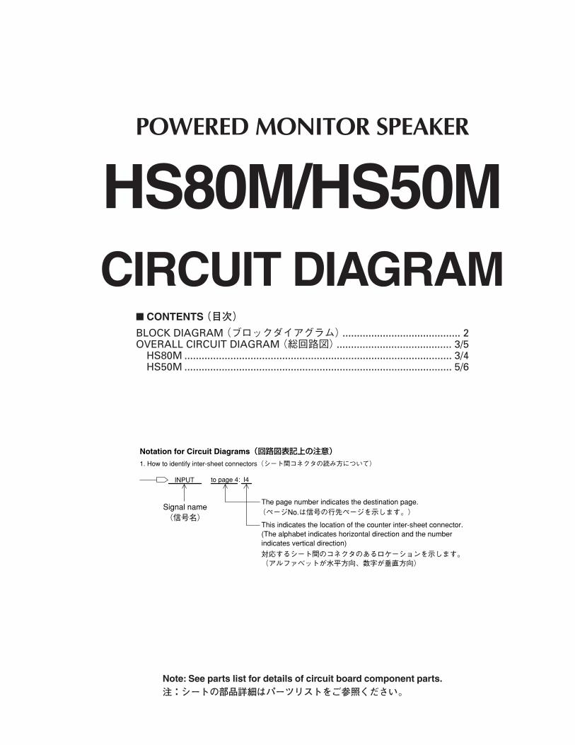
POWERED MONITOR SPEAKER
HS80M/HS50MCIRCUIT DIAGRAM
BLOCK DIAGRAM (ブロックダイアグラム)......................................... 2OVERALL CIRCUIT DIAGRAM (総回路図)........................................ 3/5
HS80M ............................................................................................. 3/4HS50M ............................................................................................. 5/6
� CONTENTS (目次)
Note: See parts list for details of circuit board component parts.注:シートの部品詳細はパーツリストをご参照ください。
INPUT
�
(ページNo.は信号の行先ページを示します。)�
�Notation for Circuit Diagrams(回路図表記上の注意)�1. How to identify inter-sheet connectors(シート間コネクタの読み方について)�
The page number indicates the destination page.
対応するシート間のコネクタのあるロケーションを示します。��(アルファベットが水平方向、数字が垂直方向)�
This indicates the location of the counter inter-sheet connector.(The alphabet indicates horizontal direction and the numberindicates vertical direction)
to page 4:
Signal name(信号名)�
I4
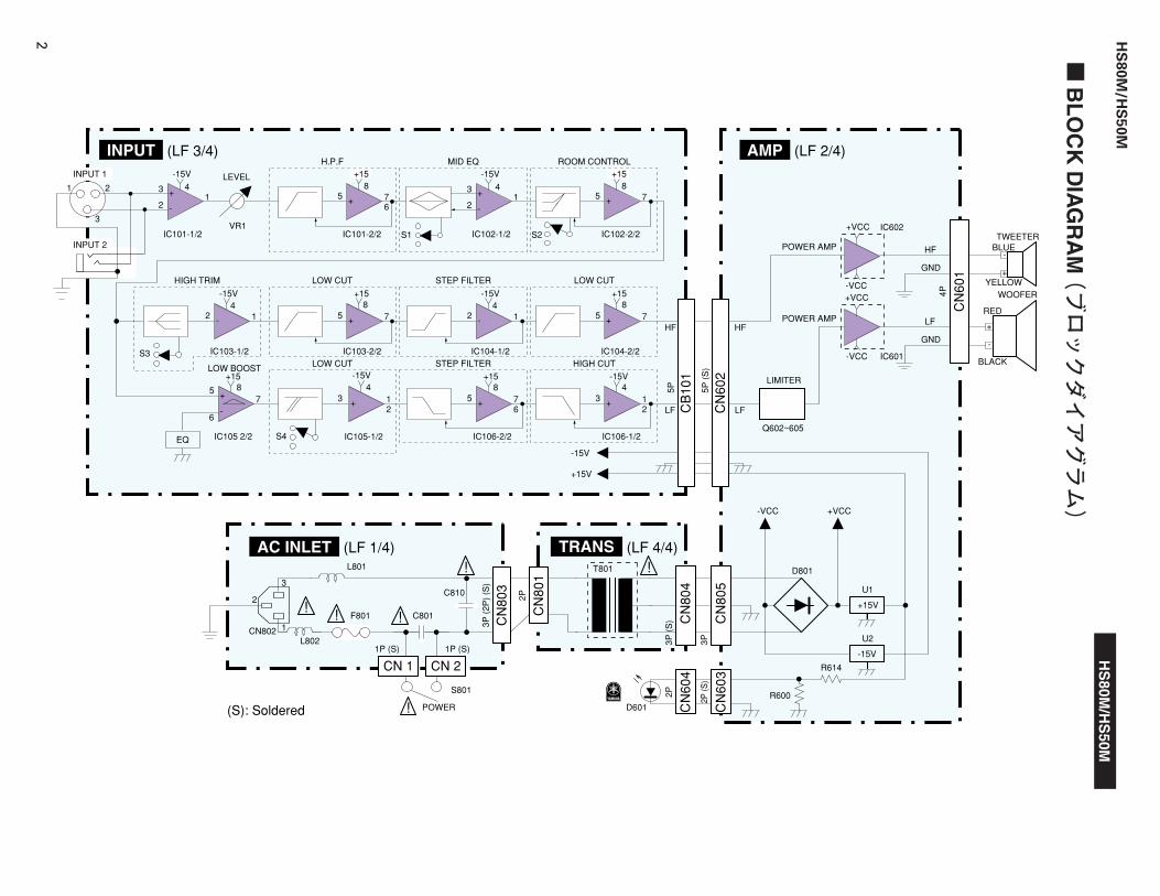
� B
LO
CK
DIA
GR
AM
(ブロックダイアグラム)
INPUT (LF 3/4) AMP
AC INLET TRANS
(LF 2/4)
(LF 4/4)(LF 1/4)
+15V
CB
101
LOW CUT LOW CUTSTEP FILTER
LOW CUT HIGH CUTSTEP FILTER
H.P.F
LEVEL
ROOM CONTROLMID EQ
LOW BOOSTLIMITER
POWER AMP
INPUT 1
INPUT 2IC102-2/2IC101-2/2
IC103-2/2
IC102-1/2
IC104-2/2
IC106-2/2IC105 2/2
+15-15V+15
+15 +15
+15 +15
1 2
3
IC101-1/2
-15V
3 +
-21 5
67 1 5 7
IC103-1/2
-15V
2 1 5 7 5 7
IC104-1/2
-15V
2 1
IC106-1/2
-15V
321
IC105-1/2
-15V
32
6
1 567
57
HIGH TRIM
VR1
44 88
4 48 8
844 8
S1 S2
S3
S4
CN
602
CN
803
CN
804
CN
805
CN
801
2
1
! ! !
!
! !3
-15V
CN
604
CN
603
CN
601
POWER AMP
LF
HF BLUE
YELLOW
RED
BLACK
TWEETER
WOOFER
-VCC +VCC
-15V
+15V
-VCC
-VCC+VCC
+VCC
+
-
GND
GND
IC602
HF
LF
HF
LF
Q602~605
D801
U1
U2
R614
R600D601
T801
C810
C801
1P (S)1P (S)
3P (
2P)
(S)
2P
2P
4P
5P 5P (
S)
3P3P (
S)
2P (S
)
F801
POWER
CN 1
(S): Soldered
CN 2
S801
EQ
L801
L802CN802
IC601
-
+
++
-
3
2 +
-
-
+
+
++
-
+
+
HS
80M/H
S50M
HS
80
M/H
S5
0M
2
A B C D E F G H I J
1
2
3
4
5
6
7
HS80M/HS50M
3
1
2
3
4
5
6
7
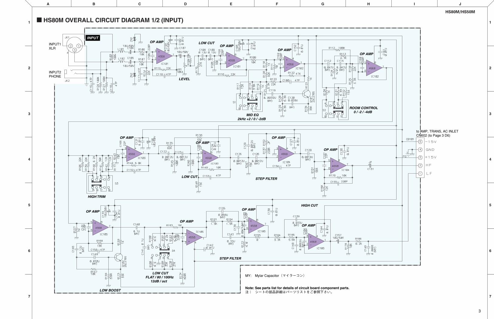
� HS80M OVERALL CIRCUIT DIAGRAM 1/2 (INPUT)
OP AMPOP AMP
OP AMPOP AMP
LEVEL
LOW CUT
LOW BOOST
STEP FILTER
STEP FILTER
HIGH CUT
LOW CUT
OP AMP
OP AMP
OP AMP
OP AMP
OP AMP
OP AMP
OP AMP
OP AMP
ROOM CONTROL0 / -2 / -4dB
MID EQ2kHz +2 / 0 / -2dB
HIGH TRIM
LOW CUTFLAT / 80 / 100Hz
12dB / oct
INPUT1XLR
INPUT2PHONE
MY: Mylar Capacitor(マイラーコン)�
�Note: See parts list for details of circuit board component parts.注: シートの部品詳細はパーツリストをご参照下さい。�
INPUT
to AMP, TRANS, AC INLETCN602 (to Page 1 xx)to AMP, TRANS, AC INLETCN602 (to Page 3 D6)
HS80M/HS50M
4
2
A B C D E F G H I J
1
3
4
5
7
6
1
2
3
4
5
6
7
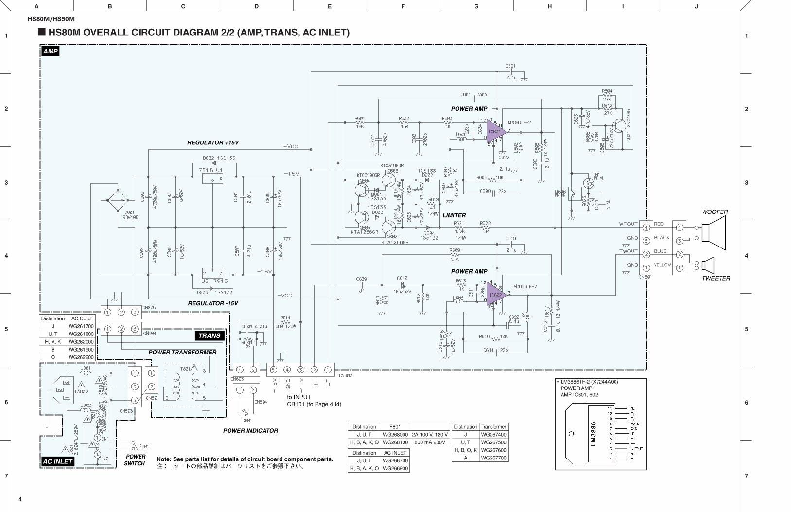
� HS80M OVERALL CIRCUIT DIAGRAM 2/2 (AMP, TRANS, AC INLET)
REGULATOR +15V
REGULATOR -15V
LIMITER
POWER AMPTWEETER
POWER AMP
POWER TRANSFORMER
POWERSWITCH
POWER INDICATOR
TRANS
AC INLET
AMP
to INPUTCB101 (to Page 4 I4)
WOOFER
��Note: See parts list for details of circuit board component parts.注: シートの部品詳細はパーツリストをご参照下さい。�
RED
BLACK
BLUE
YELLOW
Distination
J
U, T
H, A, K
B
O
AC Cord
WG261700
WG261800
WG262000
WG261900
WG262200
Distination
J, U, T
H, B, A, K, O
F801
WG268000
WG268100
2A 100 V, 120 V
800 mA 230V
Distination
J
U, T
H, B, O, K
A
Transformer
WG267400
WG267500
WG267600
WG267700
• LM3886TF-2 (X7244A00)POWER AMPAMP IC601, 602
Distination
J, U, T
H, B, A, K, O
AC INLET
WG266700
WG266900
A B C D E F G H I J
1
2
3
4
5
6
7
HS80M/HS50M
5
1
2
3
4
5
6
7
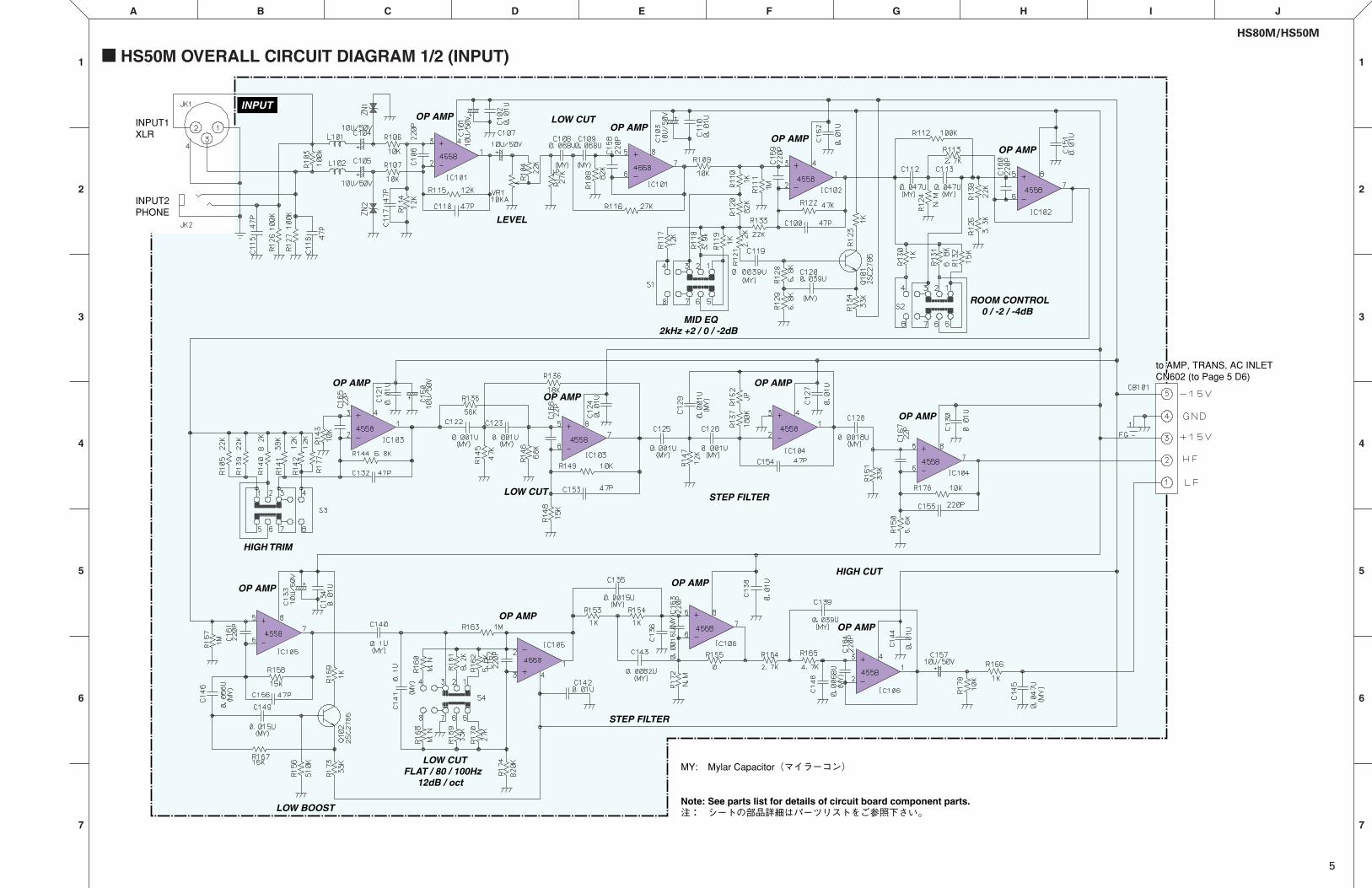
� HS50M OVERALL CIRCUIT DIAGRAM 1/2 (INPUT)
OP AMPOP AMP
OP AMPOP AMP
LEVEL
LOW CUT
LOW BOOST
STEP FILTER
STEP FILTER
HIGH CUT
LOW CUT
OP AMP
OP AMP
OP AMP
OP AMP
OP AMP
OP AMP
OP AMP
OP AMP
ROOM CONTROL0 / -2 / -4dB
MID EQ2kHz +2 / 0 / -2dB
HIGH TRIM
LOW CUTFLAT / 80 / 100Hz
12dB / oct
INPUT1XLR
INPUT2PHONE
MY: Mylar Capacitor(マイラーコン)�
�Note: See parts list for details of circuit board component parts.注: シートの部品詳細はパーツリストをご参照下さい。�
INPUT
to AMP, TRANS, AC INLETCN602 (to Page 1 xx)to AMP, TRANS, AC INLETCN602 (to Page 5 D6)
HS80M/HS50M
6
2
A B C D E F G H I J
1
3
4
5
7
6
1
2
3
4
5
6
7
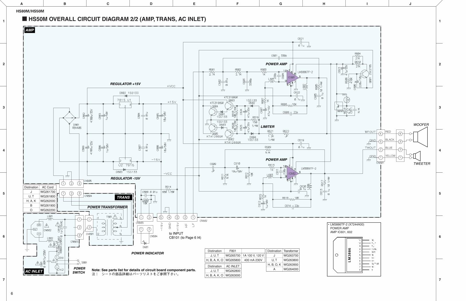
� HS50M OVERALL CIRCUIT DIAGRAM 2/2 (AMP, TRANS, AC INLET)
REGULATOR +15V
REGULATOR -15V
LIMITER
POWER AMP
POWER AMP
POWER TRANSFORMER
POWER INDICATOR
TRANS
AC INLET
AMP
to INPUTCB101 (to Page 6 I4)
POWERSWITCH
��Note: See parts list for details of circuit board component parts.注: シートの部品詳細はパーツリストをご参照下さい。�
TWEETER
WOOFER
RED
BLACK
BLUE
YELLOW
Distination
J
U, T
H, A, K
B
O
AC Cord
WG261700
WG261800
WG262000
WG261900
WG262200
Distination
J, U, T
H, B, A, K, O
F801
WG265700
WG265800
1A 100 V, 120 V
400 mA 230V
Distination
J
U, T
H, B, O, K
A
Transformer
WG263700
WG263800
WG263900
WG264000
• LM3886TF-2 (X7244A00)POWER AMPAMP IC601, 602
Distination
J, U, T
H, B, A, K, O
AC INLET
WG262800
WG263000
POWERED MONITOR SPEAKER
HS80M/HS50MPARTS LIST
OVERALL ASSEMBLY (総組立)......................................................... 2/4HS80M ................................................................................................ 2HS50M ................................................................................................ 4
ELECTRICAL PARTS (電気部品)........................................................ 3/5HS80M ................................................................................................ 3HS50M ................................................................................................ 5
� CONTENTS (目次)
Notes: DESTINATION ABBREVIATIONS
A : Australian modelB : British modelC : Canadian modelD : German modelE : European modelF : French modelH : North European modelI : Indonesian modelJ : Japanese modelK : Korean model
M : South African modelO : Chinese modelQ : South-east Asia modelT : Taiwan modelU : U.S.A. modelV : General export model (110V)W: General export model (220V)N,X: General export modelY : Export model
� WARNINGComponents having special characteristics are marked and must be replaced with parts havingspecification equal to those originally installed.
印の部品は、安全を維持するために重要な部品です。交換する場合は、安全のために必ず指定の部品をご使用ください。
• The numbers “QTY” show quantities for each unit.• The parts with “--” in “PART NO.” are not available as spare parts.• This mark “ } ” in the REMARKS column means these parts are interchangeable.• The second letter of the shaded ( ) part number is O, not zero.• The second letter of the shaded ( ) part number is I, not one.• 部品価格ランクは、変更になることがあります。• QTY欄に記されている数字は、各ユニット当たりの使用個数です。• PART NO.が“--”の部分は、サービス用部品として準備されておりません。• REMARKS欄の「 }」マークの部品は、併用部品です。• 網掛けの付いたPART NO.の 2番目の文字は「ゼロ」ではなく、「オー」です。• 網掛けの付いたPART NO.の 2番目の文字は「イチ」ではなく、「アイ」です。
HS80M/HS50M
2
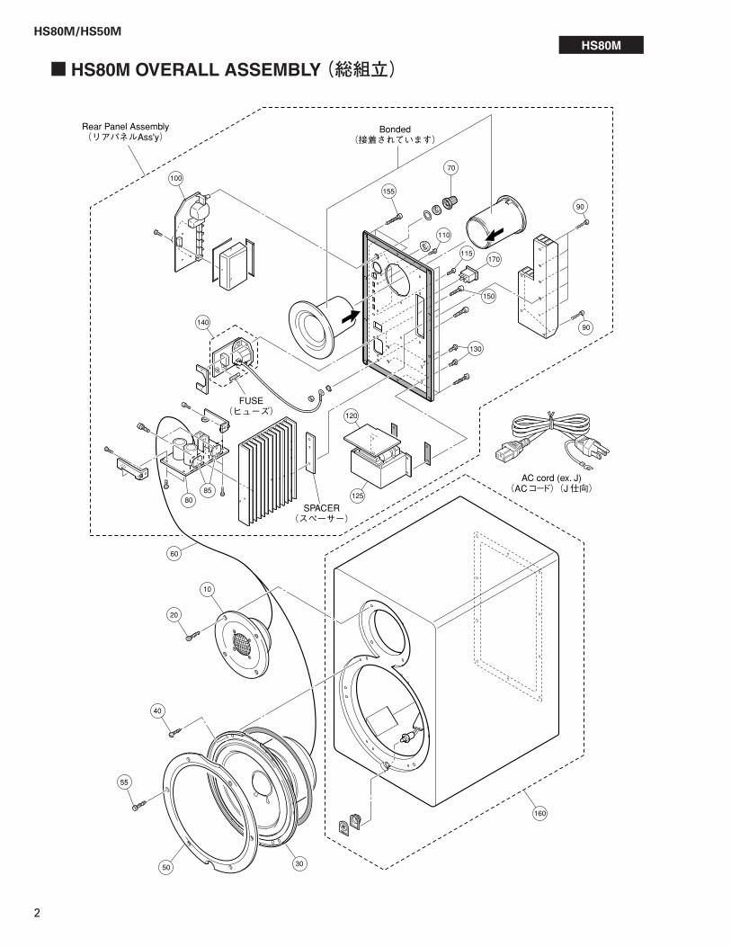
� HS80M OVERALL ASSEMBLY (総組立)
155
100
120
125
140
8085
SPACER(スぺ-サー)�
FUSE(ヒューズ)�
Rear Panel Assembly(リアパネルAss'y)�
Bonded(接着されています)�
55
AC cord (ex. J)(ACコード)(J仕向)�
70
90
90
110
170115
150
130
60
160
3050
40
20
10
HS80M
HS80M/HS50M
3
RANKQTYREMARKSDESCRIPTION 部 品 名REF NO. PART NO.
: New Parts RANK: Japan only
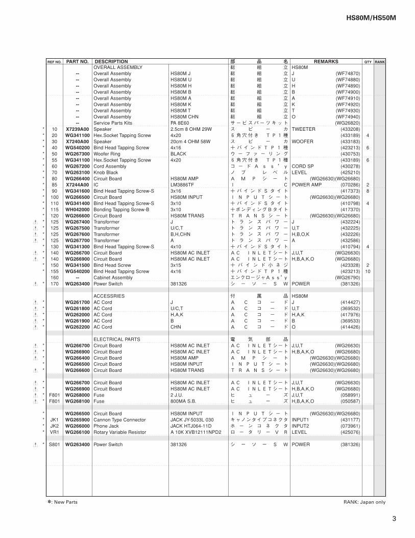
OVERALL ASSEMBLY HS80MOverall Assembly HS80M J J (WF74870)Overall Assembly HS80M U U (WF74880)Overall Assembly HS80M H H (WF74890)Overall Assembly HS80M B B (WF74900)Overall Assembly HS80M A A (WF74910)Overall Assembly HS80M K K (WF74920)Overall Assembly HS80M T T (WF74930)Overall Assembly HS80M CHN O (WF74940)Service Parts Kits PA 8E60 (WG26820)
* 10 Speaker 2.5cm 8 OHM 29W TWEETER (433208)* 20 Hex.Socket Tapping Screw 4x20 (433189) 4* 30 Speaker 20cm 4 OHM 58W WOOFER (433183)* 40 Bind Head Tapping Screw 4x16 (423213) 6* 50 Woofer Ring BLACK (430753)* 55 Hex.Socket Tapping Screw 4x20 (433189) 6* 60 Cord Assembly CORD SP (430278)* 70 Knob Black LEVEL (425210)* 80 Circuit Board HS80M AMP (WG26630)(WG26680)* 85 IC LM3886TF POWER AMP (070286) 2* 90 Bind Head Tapping Screw-S 3x16 (417373) 8* 100 Circuit Board HS80M INPUT (WG26630)(WG26680)* 110 Bind Head Tapping Screw-S 3x10 (410798) 4* 115 Bonding Tapping Screw-B 3x10 (417370)* 120 Circuit Board HS80M TRANS (WG26630)(WG26680)
s * 125 Transformer J J (432224)s * 125 Transformer U/C,T U,T (432225)s * 125 Transformer B,H,CHN H,B,O,K (432226)s * 125 Transformer A A (432586)
* 130 Bind Head Tapping Screw-S 4x10 (410794) 4s * 140 Circuit Board HS80M AC INLET J,U,T (WG26630)s * 140 Circuit Board HS80M AC INLET H,B,A,K,O (WG26680)
* 150 Bind Head Screw 3x15 (423328) 2* 155 Bind Head Tapping Screw 4x16 (423213) 10
160 Cabinet Assembly (WG26790)s * 170 Power Switch 381326 POWER (381326)
ACCESSRIES HS80Ms * AC Cord J J (414427)s * AC Cord U/C,T U,T (369532)s * AC Cord H,A,K H,A,K (417976)s * AC Cord B B (369533)s * AC Cord CHN O (414426)
ELECTRICAL PARTSs * Circuit Board HS80M AC INLET J,U,T (WG26630)s * Circuit Board HS80M AC INLET H,B,A,K,O (WG26680)s * Circuit Board HS80M AMP (WG26630)(WG26680)
* Circuit Board HS80M INPUT (WG26630)(WG26680)s * Circuit Board HS80M TRANS (WG26630)(WG26680)
s * Circuit Board HS80M AC INLET J,U,T (WG26630)s * Circuit Board HS80M AC INLET H,B,A,K,O (WG26680)s * F801 Fuse 2 J.U. J,U,T (058991)s * F801 Fuse 800MA S.B. H,B,A,K,O (050587)
* Circuit Board HS80M INPUT (WG26630)(WG26680)* JK1 Cannon Type Connector JACK JY-5033L 030 INPUT1 (431177)* JK2 Phone Jack JACK HTJ064-11D INPUT2 (073961)* VR1 Rotary Variable Resistor A 10K XVB12111NPD2 LEVEL (425076)
s * S801 Power Switch 381326 POWER (381326)
------------------
X7239A00WG341100X7240A00WG540200WG267300WG341100WG267200WG263100WG266400X7244A00WG341600WG266500WG341400WH042000WG266600WG267400WG267500WG267600WG267700WG341300WG266700WG266900WG341500WG540200
--WG263400
WG261700WG261800WG262000WG261900WG262200
WG266700WG266900WG266400WG266500WG266600
WG266700WG266900WG268000WG268100
WG266500WG265900WG266000WG266100
WG263400
総 組 立総 組 立総 組 立総 組 立総 組 立総 組 立総 組 立総 組 立総 組 立サービスパーツキットス ピ ー カ6角穴付き TP1種ス ピ ー カ+ バ イ ン ド T P 1 種ウ ー フ ァ ー リ ン グ6角穴付き TP1種コ ー ド A s s ’yノ ブ レ ベ ルA M P シ ー トI C+ バ イ ン ド S タ イ トI N P U T シ ー ト+ バ イ ン ド S タ イ ト+ボンディングBタイトT R A N S シ ー トト ラ ン ス パ ワ ート ラ ン ス パ ワ ート ラ ン ス パ ワ ート ラ ン ス パ ワ ー+ バ イ ン ド S タ イ トAC INLETシートAC INLETシート+ バ イ ン ド 小 ネ ジ+ バ イ ン ド T P 1 種エンクロージャAss’yシ ー ソ ー S W
付 属 品A C コ ー ドA C コ ー ドA C コ ー ドA C コ ー ドA C コ ー ド
電 気 部 品AC INLETシートAC INLETシートA M P シ ー トI N P U T シ ー トT R A N S シ ー ト
AC INLETシートAC INLETシートヒ ュ ー ズヒ ュ ー ズ
I N P U T シ ー トキャノンタイプコネクタホ ー ン コ ネ ク タロ ー タ リ ー V R
シ ー ソ ー S W
HS80M/HS50M
4
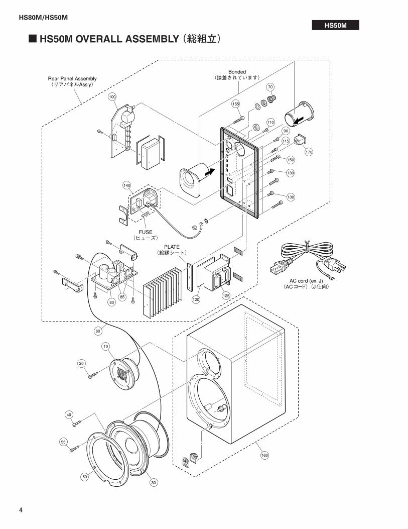
� HS50M OVERALL ASSEMBLY (総組立)
Rear Panel Assembly(リアパネルAss'y)�
155
100
120125
140
8085
PLATE(絶縁シート)�
AC cord (ex. J)(ACコード)(J仕向)�
FUSE(ヒューズ)�
Bonded(接着されています)�
70
110
90
170
115
150
130
130
10
20
60
40
55
50
30
160
HS50M

HS80M/HS50M
5
RANKQTYREMARKSDESCRIPTION 部 品 名REF NO. PART NO.
: New Parts RANK: Japan only
OVERALL ASSEMBLY HS50MOverall Assembly HS50M J J (WF74780)Overall Assembly HS50M U U (WF74790)Overall Assembly HS50M H H (WF74800)Overall Assembly HS50M B B (WF74810)Overall Assembly HS50M A A (WF74820)Overall Assembly HS50M K K (WF74830)Overall Assembly HS50M T T (WF74840)Overall Assembly HS50M CHN O (WF74850)Service Parts Kits PA 8E59 (WG26620)
* 10 Speaker 1.9cm 8 OHM 19W TWEETER (433207)* 20 Hex.Socket Tapping Screw 4x20 (433189) 4* 30 Speaker 13cm 4 OHM 38W WOOFER (433206)* 40 Bind Head Tapping Screw 4x16 (423213) 4* 50 Woofer Ring BLACK (430752)* 55 Hex.Socket Tapping Screw 4x20 (433189) 4* 60 Cord Assembly CORD SP (430277)* 70 Knob Black LEVEL (425210)* 80 Circuit Board HS50M AMP (WG26230)(WG26290)* 85 IC LM3886TF POWER AMP (070286) 2* 90 Bind Head Tapping Screw-S 3x10 (410798) 3* 100 Circuit Board HS50M INPUT (WG26230)(WG26290)* 110 Bind Head Tapping Screw-S 3x10 (410798) 4* 115 Bonding Tapping Screw-B 3x10 (417370)* 120 Circuit Board HS50M TRANS (WG26230)(WG26290)
s * 125 Transformer J J (432220)s * 125 Transformer U/C,T U,T (432221)s * 125 Transformer B,H,CHN H,B,O,K (432222)s * 125 Transformer A A (432585)
* 130 Bind Head Tapping Screw-S 4x10 (410794) 4s * 140 Circuit Board HS50M AC INLET J,U,T (WG26230)s * 140 Circuit Board HS50M AC INLET H,B,A,K,O (WG26290)
* 150 Bind Head Screw 3x15 (423328) 2* 155 Bind Head Tapping Screw 4x16 (423213) 10
160 Cabinet Assembly (WG26420)s * 170 Power Switch 381326 POWER (381326)
ACCESSRIES HS50Ms * AC Cord J J (414427)s * AC Cord U/C,T U,T (369532)s * AC Cord H,A,K H,A,K (417976)s * AC Cord B B (369533)s * AC Cord CHN O (414426)
ELECTRICAL PARTSs * Circuit Board HS50M AC INLET J,U,T (WG26230)s * Circuit Board HS50M AC INLET H,B,A,K,O (WG26290)
* Circuit Board HS50M AMP (WG26230)(WG26290)* Circuit Board HS50M INPUT (WG26230)(WG26290)* Circuit Board HS50M TRANS (WG26230)(WG26290)
s * Circuit Board HS50M AC INLET J,U,T (WG26230)s * Circuit Board HS50M AC INLET H,B,A,K,O (WG26290)s * F801 Fuse 1 J.U. J,U,T (339124)s * F801 Fuse 400MA S.B. H,B,A,K,O (075126)
* Circuit Board HS50M INPUT (WG26230)(WG26290)* JK1 Cannon Type Connector JACK JY-5033L 030 INPUT1 (431177)* JK2 Phone Jack JACK HTJ064-11D INPUT2 (073961)* VR1 Rotary Variable Resistor A 10K XVB12111NPD2 LEVEL (425076)
s * S801 Power Switch 381326 POWER (381326)
------------------
X7237A00WG341100X7238A00WG540200WG263600WG341100WG263500WG263100WG262400X7244A00WG341400WG262500WG341400WH042000WG262600WG263700WG263800WG263900WG264000WG341300WG262800WG263000WG341500WG540200
--WG263400
WG261700WG261800WG262000WG261900WG262200
WG262800WG263000WG262400WG262500WG262600
WG262800WG263000WG265700WG265800
WG262500WG265900WG266000WG266100
WG263400
総 組 立総 組 立総 組 立総 組 立総 組 立総 組 立総 組 立総 組 立総 組 立サービスパーツキットス ピ ー カ6角穴付き TP1種ス ピ ー カ+ バ イ ン ド T P 1 種ウ ー フ ァ ー リ ン グ6角穴付き TP1種コ ー ド A s s ’yノ ブ レ ベ ルA M P シ ー トI C+ バ イ ン ド S タ イ トI N P U T シ ー ト+ バ イ ン ド S タ イ ト+ボンディングBタイトT R A N S シ ー トト ラ ン ス パ ワ ート ラ ン ス パ ワ ート ラ ン ス パ ワ ート ラ ン ス パ ワ ー+ バ イ ン ド S タ イ トAC INLETシートAC INLETシート+ バ イ ン ド 小 ネ ジ+ バ イ ン ド T P 1 種エンクロージャAss’yシ ー ソ ー S W
付 属 品A C コ ー ドA C コ ー ドA C コ ー ドA C コ ー ドA C コ ー ド
電 気 部 品AC INLETシートAC INLETシートA M P シ ー トI N P U T シ ー トT R A N S シ ー ト
AC INLETシートAC INLETシートヒ ュ ー ズヒ ュ ー ズ
I N P U T シ ー トキャノンタイプコネクタホ ー ン コ ネ ク タロ ー タ リ ー V R
シ ー ソ ー S W