Yaesu FTDX101MP MF, HF and 6-Meter Transceiver
6
www.arrl.org QST December 2020 1 Product Review Mark J. Wilson, K1RO, [email protected] Bottom Line The Yaesu FTDX101MP is a very effective, full- size, full-featured, 200 W PEP transceiver that would work well in most stations, especially those involved in serious contesting or DX chasing where strong close-in signals abound. Yaesu FTDX101MP MF, HF and 6-Meter Transceiver Reviewed by Joel R. Hallas, W1ZR [email protected] In the November 2019 issue of QST, we reviewed Yaesu’s FTDX101D, a 100 W, SSB, CW, AM, FM, and digital-mode transceiver for 160 through 6 meters. In that review, we mentioned that there was also a 200 W version available, the FTDX101MP, which we review this month. You may wish to look at the earlier review to follow along in our discussion of the differ- ences. For those interested in etymology, the “MP” of the product name is in honor of the founder of Yaesu, the late Sako Hasegawa, JA1MP. A Full-Size HF Transceiver While many manufacturers strive to offer a compact, travel-friendly transceiver, the FTDX101MP configura- tion is based on different design objectives. This trans- ceiver is designed to sit in the center of your operating position with a full-size front panel that includes dedi- cated concentric controls for most functions. This radio will be an easy-to-access focal point of a full-featured fixed-station layout. Controls are well marked and identified, but most are not illuminated, so your station should be well-lighted to see the control labels, at least until your muscle memory is well- programmed. Changes Between the Models A look at the front panels of the two transceivers con- firms that, other than the model numbers on the upper right, the two panels are identical, with the same con- trols and indicators in all the same places. There are, however, some important differences that are appar- ent upon a deeper inspection. Of course, the most significant difference is that the maximum RF output power of the ’MP is 200 W ver- sus 100 W for the ’D model. This difference, 3 dB, or half an S-unit, doesn’t sound like a big improvement, but may be important to some users. For example:
Transcript of Yaesu FTDX101MP MF, HF and 6-Meter Transceiver

www.arrl.org QST December 2020 1
Product ReviewMark J. Wilson, K1RO, [email protected]
Bottom LineThe Yaesu FTDX101MP is a very effective, full-size, full-featured, 200 W PEP transceiver that would work well in most stations, especially those involved in serious contesting or DX chasing where strong close-in signals abound.
Yaesu FTDX101MP MF, HF and 6-Meter Transceiver
Reviewed by Joel R. Hallas, [email protected]
In the November 2019 issue of QST, we reviewed Yaesu’s FTDX101D, a 100 W, SSB, CW, AM, FM, and digital-mode transceiver for 160 through 6 meters. In that review, we mentioned that there was also a 200 W version available, the FTDX101MP, which we review this month. You may wish to look at the earlier review to follow along in our discussion of the differ-ences. For those interested in etymology, the “MP” of the product name is in honor of the founder of Yaesu, the late Sako Hasegawa, JA1MP.
A Full-Size HF TransceiverWhile many manufacturers strive to offer a compact, travel-friendly transceiver, the FTDX101MP configura-tion is based on different design objectives. This trans-ceiver is designed to sit in the center of your operating position with a full-size front panel that includes dedi-cated concentric controls for most functions.
This radio will be an easy-to-access focal point of a full-featured fixed-station layout. Controls are well marked and identified, but most are not illuminated, so your station should be well-lighted to see the control
labels, at least until your muscle memory is well- programmed.
Changes Between the ModelsA look at the front panels of the two transceivers con-firms that, other than the model numbers on the upper right, the two panels are identical, with the same con-trols and indicators in all the same places. There are, however, some important differences that are appar-ent upon a deeper inspection.
Of course, the most significant difference is that the maximum RF output power of the ’MP is 200 W ver-sus 100 W for the ’D model. This difference, 3 dB, or half an S-unit, doesn’t sound like a big improvement, but may be important to some users. For example:

2 December 2020 QST www.arrl.org
Table 1 Yaesu FTDX101MP, serial number 9M060545Manufacturer’s Specifications Measured in the ARRL LabFrequency coverage: Receive, 0.03 – Receive and transmit, as specified, 75 MHz; transmit, 160 – 6 meter amateur including 60 meters on 5.332, 5.348, bands only. 5.3585, 5.373, and 5.405 MHz (preset channels).Power requirement: Transmit, 720 VA, Transmit, typically 560 VA, 642 VA max. Receive (with signal), 120 VA. 310 VA (AM) at maximum RF power Receive, 54 VA (max brightness). Power off, <1 mA.Modes of operation: SSB, CW, AM, FM, As specified. FSK, PSK, SSB data modes.
Main Receiver Main Receiver Dynamic Testing*SSB/CW sensitivity (preamp 2 on): Noise floor (MDS), 500 Hz bandwidth, 0.16 µV (1.8 – 30 MHz) 600 Hz roofing filter: 0.125 µV (50 – 54 MHz) Preamp Off P1 P2 0.16 µV (70 – 70.5 MHz). 0.137 MHz –121 –131 –118 dBm 0.475 MHz –124 –133 –136 dBm 1.0 MHz –125 –134 –138 dBm 3.5 MHz –125 –133 –138 dBm 14 MHz –125 –134 –138 dBm 50, 70 MHz –127 –136 –138 dBmADC overload level: Not specified. >+10 dBm.Noise figure: Not specified. Preamp off/1/2, 14 MHz: 22/13/9 dB; 50 MHz, 20/11/9 dB.AM sensitivity: 6 kHz BW, 10 dB (S+N/N), 10 dB (S+N)/N, 1-kHz tone, preamp 2 on: 30% modulation, 9 kHz BW: 6.3 µV (0.5 – 1.8 MHz) Preamp Off P1 P2 2.0 µV (1.8 – 30 MHz) 1.0 MHz 3.39 1.15 0.79 µV 1.0 µV (50 – 54 MHz) 3.88 MHz 4.12 1.43 0.94 µV 2.0 µV (70 – 70.5 MHz). 29.0 MHz 2.98 1.02 0.87 µV 50.4 MHz 2.82 1.08 0.94 µV 70.4 MHz 3.63 1.30 1.23 µVFM sensitivity: 12 kHz BW, 12 dB SINAD, For 12 dB SINAD, 3 kHz deviation, preamp 2 on: 16 kHz BW: 0.25 µV (28 – 30 MHz) Preamp Off P1 P2 0.20 µV (50 – 54 MHz) 29 MHz 1.17 0.41 0.35 µV 0.25 µV (70 – 70.5 MHz). 52 MHz 1.06 0.39 0.35 µV 70 MHz 1.03 0.35 0.33 µVSpectral sensitivity: Not specified. Panadapter and waterfall, preamp Off/1/2 14 MHz, –120/–129/–138 dBm 50 MHz, –125/–133/–141 dBm 3DSS, preamp Off/1/2 14 MHz, –121/–130/–137 dBm 50 MHz, –125/–133/–141 dBmBlocking gain compression dynamic Blocking gain compression dynamic range: Not specified. range, 500 Hz BW, 600 Hz roofing filter**: 20 kHz offset 5/2 kHz offset Preamp Off/P1/P2 Preamp off 3.5 MHz >135/>143/145 >135/135 dB 14 MHz >135/>144/147 >135/>135 dB 50 MHz >137/139/133 >137/>137 dBReciprocal mixing dynamic range: 14 MHz, 20/5/2 kHz offset: 130/128/125 dB, Not specified. for 600 and 300 Hz roofing filter.
ARRL Lab Two-Tone IMD Testing (600 Hz roofing filter, 500 Hz bandwidth) Measured Measured Band/Preamp Spacing IMD Level Input Level IMD DR 3.5 MHz/Off 20 kHz –125 dBm –20 dBm 105 dB –97 dBm –5 dBm 14 MHz/Off 20 kHz –125 dBm –13 dBm 112 dB –97 dBm –5 dBm 14 MHz/P1 20 kHz –134 dBm –22 dBm 112 dB –97 dBm –10 dBm 14 MHz/P2 20 kHz –138 dBm –30 dBm 108 dB –97 dBm –17 dBm 14 MHz/Off 5 kHz –125 dBm –13 dBm 112 dB –97 dBm –5 dBm 14 MHz/Off 2 kHz –125 dBm –15 dBm 110 dB –97 dBm –5 dBm
KEY:
Measurements are for Main receiver with preamp off.Bars off the graph indicate values over scale.
QS2012-PR147
θ
TX50 kHz –15910 kHz –160
–110 –150
Transmit Phase Noise (dB)–90 –150
5 kHz –95500 Hz –53
–55 –95
Transmit Keying Sidebands (dB)–35 –70
bw
TX
I9
TXWorst case 17 m –51Typical –57
–20 –70
Transmit Ninth-order IMD (dB)
TX
I3
Worst case 17 m –33Typical –38
–20 –35
Transmit Third-order IMD (dB)
20 m 110
50 110
2 kHz Third-order IMD Dynamic Range (dB)
I3
2k
20 m >13580 m >135
70 140
2 kHz Blocking Gain Compression (dB)
2k
BG
2k
RM20 m 125
60 140
2 kHz Reciprocal Mixing Dynamic Range (dB)
20 m 11280 m 105
50 110
20 kHz Third-order IMD Dynamic Range (dB)
I3
20k
20 m >13580 m >135
70 140
20 kHz Blocking Gain Compression (dB)
20k
BG
60 140
20 kHz Reciprocal Mixing Dynamic Range (dB)
20k
RM20 m 130
Yaesu FTDX101MPKey Measurements Summary

www.arrl.org QST December 2020 3
Figure 3 — Spectral display of the Yaesu FTDX101MP transmitter output during phase-noise testing. Power output is 200 W on the 14 MHz band (red trace), 50 W on the 14 MHz band (blue trace), and 200 W on the 50 MHz band (green trace). The carrier, off the left edge of the plot, is not shown. This plot shows phase noise 100 Hz to 1 MHz from the carrier. The reference level is –120 dBc/Hz, and the vertical scale is 5 dB per division.
Figure 1 — CW keying waveform for the Yaesu FTDX101MP showing the first two dits in full-break-in (QSK) mode using external keying and the default rise time setting. Equivalent keying speed is 60 WPM. The upper trace is the actual key closure; the lower trace is the RF envelope. (Note that the first key closure starts at the left edge of the figure.) Horizontal divisions are 10 ms. The transceiver was being operated at 200 W output on the 14 MHz band.
Figure 2 — Spectral display of the Yaesu FTDX101MP transmitter during keying sideband testing. Equivalent keying speed is 60 WPM using external keying and the default rise time setting. Spectrum analyzer resolution bandwidth is 10 Hz, and the sweep time is 30 seconds. The transmitter was being operated at 200 W PEP output on the 14 MHz band, and this plot shows the transmitter output ±5 kHz from the carrier. The reference level is 0 dBc, and the vertical scale is in decibels.
0.01 0.02 0.03 0.04 0.05 0.06 0.07 0.08Time (s)
0
QS2012-ProdRev01
Frequency (kHz)fcfc−4 fc−2 fc+2 fc+4
Res
pons
e (d
B)
–100
–90
–80
–70
–60
–50
–40
–30
–20
–10
0QS2012-ProdRev02
−170
−160
−150
−140
−130
−120
Leve
l (dB
c/H
z)
100 Hz 1 kHz 10 kHz 100 kHz 1 MHzFrequency Offset
QS2012-ProdRev03
14 MHz, 200 W14 MHz, 50W50 MHz, 200 W
Measured Measured Band/Preamp Spacing IMD Level Input Level IMD DR50 MHz/Off 20 kHz –127 dBm –22 dBm 105 dB
–97 dBm –13 dBm
50 MHz/P2 20 kHz –138 dBm –36 dBm 102 dB –97 dBm –24 dBm
Second-order intercept point: Preamp Off/P1/P2 Not specified. 14 MHz, +67/+67/+67 dBm
21 MHz, +63/+61/+61 dBm 50 MHz, +59/+57/+57 dBm
IF and image rejection: IF, ≥60 dB (1.8 – IF rejection, VC off/on: 7 MHz, 72/105 dB; 28 MHz, VC on), ≥60 dB (50 MHz); image, 10.1 MHz, 70/100 dB; 14 MHz, ≥70 dB (1.8 – 28 MHz), ≥60 dB (50 MHz). 102/105 dB, 50 MHz, 105/105 dB.
Image rejection, VC off/on: 7 MHz, 88/95 dB; 10.1 MHz, 78/105 dB; 14 MHz, 70/89 dB; 50 MHz, 69/69 dB.
Noise reduction: Not specified. Up to 20 dB.FM two-tone third-order IMD dynamic: 20 kHz offset, P2 on: 29 MHz, 86 dB†; range: Not specified. 52 MHz, 86 dB. 10 MHz offset, P2 on:
29 MHz, 119 dB; 52 MHz, 110 dB.Squelch sensitivity: (preamp 2 on) FM, 28 – FM, P2 on: 29 MHz, 0.27 – 0.58 µV; 30 MHz, 0.25 µV, 50 – 54 MHz, 0.2 µV, 52 MHz, 0.27 – 0.57 µV. SSB, CW AM, 2 µV. HF squelch: 1.19 – 13.3 µV.S-meter sensitivity: Not specified. S-9 signal, preamp Off/P1/P2:
14 MHz, 132/46.7/17.6 µV; 50 MHz, 99/38/14.6 µV; Scaling: 3 dB per S-unit.
Notch filter depth: Not specified. Tunable notch filter, >70 dB; auto notch > 70 dB, attack time 2 ms for one or two tones.
IF/audio response: Not specified. Range at –6 dB points:‡ CW (500 Hz BW): 453 – 945 Hz; Equivalent Rectangular BW: 489 Hz; SSB (2.4 kHz BW): 289 – 2406 Hz; AM (9 kHz BW): 98 – 1668 Hz.
Audio output: 2.5 W at 10% THD at 4 Ω. As specified. THD 0.3% at 1 VRMS. Receive processing delay time: Not specified. 25 ms.
Transmitter Transmitter Dynamic TestingPower output: 5 – 200 W (SSB, CW, FM), SSB, CW, FM (typical): 1.8 – 30 MHz, 5 – 50 W (AM). 5.0 – 196 W; 50 – 54 MHz; 4.9 – 185 W;
AM (typical): 1.8 – 30 MHz, 5.0 – 48 W; 50.4 MHz, 5.1 – 46 W.
Spurious-signal and harmonic suppression: HF, 69 dB typical; worst case, 58 dB (80 m); ≥50 dB (HF); ≥66 dB (50 MHz). 50 MHz, 71 dB. Complies with FCC
emission standards.Third-order intermodulation distortion (IMD) 3rd/5th/7th/9th order, 200 W PEP: products: Not specified. –38/–46/–51/–57 dB (HF typical)
–33/–40/–45/–51 dB (worst case, 17 m)–37/–44/–47/–54 dB (14 MHz)–40/–44/–51/–58 dB (50 MHz)
At 50 W PEP RF output: –35/–44/–54/–63 dB (14 MHz)–40/–47/–58/–72 dB (50 MHz)
CW keyer speed range: Not specified. 4 to 56 WPM. Iambic mode A, B, Y, ACS, semi-automatic.
CW keying characteristics: Not specified. See Figures 1 and 2.Transmit-receive turnaround time (PTT S-9 signal, AGC fast, SSB: 54 ms; release to 50% audio output: Not specified. AGC fast, CW, full break-in: 30 ms.Receive-transmit turnaround time (tx delay): SSB, 24 ms; FM, 18 ms (29 & 52 MHz). Not specified.Transmit phase noise: Not specified. See Figure 3.Amplifier key line closure to RF output: As specified. 15 – 30 ms (adjustable).Size (height, width, depth, with protrusions): 5.9 × 16.5 × 15 inches; weight, 31.3 pounds.Second-order intercept points were determined using S-5 reference. *Sub receiver test results were very similar to the main receiver test results. See www.arrl.org/qst_in_depth for complete measurements for the sub receiver.**Blocking dynamic range exceeds these values. No blocking was observed with up to +10 dBm signal at the antenna jack, the maximum level used in ARRL Lab testing. †Measurement is noise limited at the value indicated.‡Default values; bandwidth is adjustable.
Manufacturer’s Specifications Measured in the ARRL Lab

4 December 2020 QST www.arrl.org
Amateurs who frequent 30 meters can operate up tothe 200 W legal limit, without need for an additionalamplifier.
While 3 dB will not make a noticeable difference dur-ing casual contacts when signals are strong, it caneasily make the difference between completing acontact and frustration while trying to break througha pileup or when signals are barely out of the noise.
Some older linear amplifiers need a bit more than100 W drive to yield full-rated output. In addition,those amplifiers needing close to 100 W drive willgenerally see a more linear signal from a transceiveroperated well below its full-power output.
Both FTDX101 models operate from external powersupplies. The ’MP comes with an included dedicatedpower supply to provide the 50 V required by the200 W power amplifier stage. If you were to buy adedicated 13.8 V, 23 A supply for the 100 W ’Dmodel, it might come out about the same in terms ofrequired space. If you already have a 13.8 V dc dis-tribution system in your station with sufficient capac-ity, the ’MP model will add an additional box to yourstation’s equipment inventory (and space require-ments).
The ’MP model includes two features that are offeredas options on the ’D model (and both must be speci-
fied on initial order). These are the 300 Hz band-width CW/data roofing filter ($260), and the VCT101 motor-driven RF preselector for the second receiver ($330). Note that both models include a 600 Hz roof-ing filter as standard equipment, along with select-able DSP filtering down to a bandwidth of 50 Hz, and both models include the pre selector in the pri-mary receiver. In addition to providing additional pro-tection from strong close-in signals in CW mode, the 300 Hz filter also provides a small improvement in the already excellent receiver close-in dynamic per-formance for CW or data mode operation. The ‘MP model also brings with it multiple subtle improve-ments to the display system, presented on a 7-inch TFT (thin-film transistor) color touch-panel display.
If you were to buy an FTDX101D with the optional 300 Hz filter, the optional preselector for the second receiver, and a typical 13.8 V, 23 A power supply, you would add about 60% of the $1,300 (list) price differ-ence between the two radios, perhaps making it easier to decide to purchase the more-powerful ’MP version that includes those functions in its base price.
How It WorksBoth FTDX101 models make use of traditional down-converting superhet architectures in both of the dual
Lab Notes: Yaesu FTDX101MP
Bob Allison, WB1GCMReceiver testing for FTDX101MP indicates both main and sub receiver offer performance virtually identical to that of the FTDX101D reviewed in the November 2019 issue of QST. Two-tone, third-order IMD dynamic range on 20 meters is the highest we have measured, and the receiver exhibits excellent reciprocal mixing dynamic range (RMDR) and blocking gain compression dynamic range as well (see the FTDX101D review for more information).Transmit intermodulation distortion (IMD) in the FTDX101MP is reason-ably low. We generally look for third/fifth/seventh/ninth-order IMD prod-ucts to be no higher than –30/–40/ –50/–60 dB relative to full PEP out-put. The seventh- and ninth-order products must be kept as low as possible, as they will cause the most interference on adjacent frequen-cies. The FTDX101MP transmit IMD
products are close to or exceed this performance at full PEP power out-put. Other operators on the band hearing the FTDX101MP will enjoy a respectably clean transmitted signal. At the 50 W PEP output level, typi-cally the power level needed to drive an RF power amplifier, the distortion products are even lower. As always, monitor the automatic level control (ALC) and keep the ALC in the spec-ified range when speaking, and keep the ALC level at zero when transmit-ting digital modes, such as FT8. Transmit phase noise is very low, as shown in Figure 3. At 100 Hz away from the carrier, the transmit phase noise is about the lowest we’ve observed in the ARRL Lab. This means considerably less potential interference to other operators lis-tening very close to the transmitted frequency. Farther away from the carrier, the phase noise is even
lower, approaching the noise floor of the test instrument. Excellent keying waveform shaping, with no shorten-ing of the first transmitted dit, and a correspondingly narrow CW band-width, makes for a clean transmitter, a complement to this model’s top performing receiver. My only critique of the test data is the S-meter scaling. The widely adopted convention for S-meters is a 50 µV signal level for S-9, and scaling of 6 dB per S-unit. With Preamp 1 engaged, the FTDX101MP’s S-meter reads close to S-9 with a 50 µV (–73 dBm) signal level input at the antenna jack, but the scaling is 3 dB per S-unit. This scaling means S-0 is equal to a sig-nal level of –100 dBm, typical of other Yaesu transceivers measured in the ARRL Lab. If the S-meter used 6 dB per S-unit scaling, S-0 would equal –127 dBm.
www.arrl.org QST December 2020 5
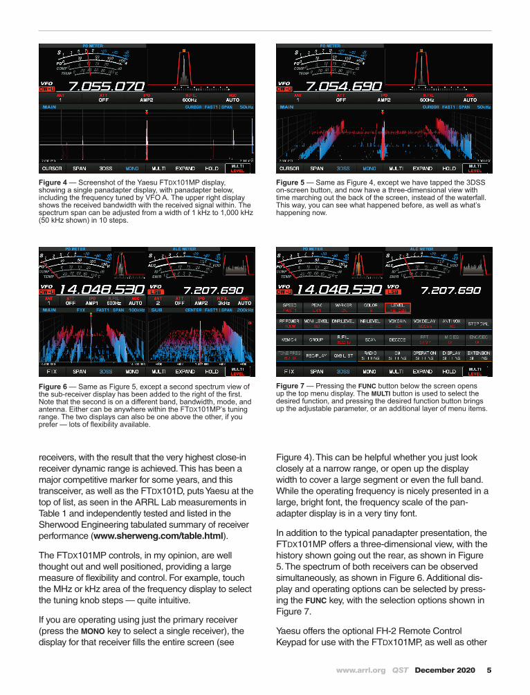
Figure 6 — Same as Figure 5, except a second spectrum view of the sub-receiver display has been added to the right of the first. Note that the second is on a different band, bandwidth, mode, and antenna. Either can be anywhere within the FTDX101MP’s tuning range. The two displays can also be one above the other, if you prefer — lots of flexibility available.
Figure 7 — Pressing the FUNC button below the screen opens up the top menu display. The MULTI button is used to select the desired function, and pressing the desired function button brings up the adjustable parameter, or an additional layer of menu items.
Figure 4 — Screenshot of the Yaesu FTDX101MP display, showing a single panadapter display, with panadapter below, including the frequency tuned by VFO A. The upper right display shows the received bandwidth with the received signal within. The spectrum span can be adjusted from a width of 1 kHz to 1,000 kHz (50 kHz shown) in 10 steps.
Figure 5 — Same as Figure 4, except we have tapped the 3DSS on-screen button, and now have a three-dimensional view with time marching out the back of the screen, instead of the waterfall. This way, you can see what happened before, as well as what’s happening now.
receivers, with the result that the very highest close-in receiver dynamic range is achieved. This has been a major competitive marker for some years, and this transceiver, as well as the FTDX101D, puts Yaesu at the top of list, as seen in the ARRL Lab measurements in Table 1 and independently tested and listed in the Sherwood Engineering tabulated summary of receiver performance (www.sherweng.com/table.html).
The FTDX101MP controls, in my opinion, are well thought out and well positioned, providing a large measure of flexibility and control. For example, touch the MHz or kHz area of the frequency display to select the tuning knob steps — quite intuitive.
If you are operating using just the primary receiver (press the MONO key to select a single receiver), the display for that receiver fills the entire screen (see
Figure 4). This can be helpful whether you just look closely at a narrow range, or open up the display width to cover a large segment or even the full band. While the operating frequency is nicely presented in a large, bright font, the frequency scale of the pan-adapter display is in a very tiny font.
In addition to the typical panadapter presentation, the FTDX101MP offers a three-dimensional view, with the history shown going out the rear, as shown in Figure 5. The spectrum of both receivers can be observed simultaneously, as shown in Figure 6. Additional dis-play and operating options can be selected by press-ing the FUNC key, with the selection options shown in Figure 7.
Yaesu offers the optional FH-2 Remote Control Keypad for use with the FTDX101MP, as well as other

6 December 2020 QST www.arrl.org
Yaesu transceivers. While all functions on the remote can be performed from the transceiver’s front panel, the FH-2 makes it easier to perform some functions, particularly operating the voice memories and CW keyer memories. Yaesu also recently introduced the SCU-LAN10 unit for remote control of the FTDX101D and FTDX101MP transceivers.
While many manufacturers have chosen to use a simpler direct-sampling SDR architecture, with potential benefits in terms of reduced spurious responses, Yaesu’s use of the traditional superhet approach allows a receiver with higher dynamic range than that limited by the closer-to-antenna analog-to-digital conversion stage required in direct sampling receivers. Some day that will likely no longer be a limit, but for now, superhets seem to have the receiver performance edge in amateur transceivers.
On the Air with the FTDX101MPThe FTDX101MP worked well as the primary transceiver at W1ZR over a number of weeks. I made contacts on both CW and SSB, all with reports of good signal quality. In addition to being easy for me to operate with a minimum learning curve, the operators on the other end also had an easy time copying me on both modes, with me using the Yaesu SSM-75G hand mic for SSB. The operating experience is essentially identical to the FTDX101D — refer to the November 2019 review for more information.
DocumentationThe FTDX101MP comes with a 122-page Operation Manual. A complete schematic pack-age is provided on eight double-sided 16 × 12 inch sheets and a 21-page CAT Operation Reference Manual is available for download from the Yaesu website. The Operation Manual does a reasonably good job at getting you started with the radio. The CAT Operation Reference provides a detailed description of the command set needed to communicate from PC to radio — perfect if you want to write your own CAT software, but not so useful in helping you set up a connection from the radio to the CAT PC software that most of us will elect to run on our PCs.
Manufacturer: Yaesu USA, 6125 Phyllis Dr., Cypress, CA 90630; www.yaesu.com. Price: Yaesu FTDX101MP, $4,400; FH-2 Remote Control Keypad; $99.