Y-IO, DHE180&240 Sunline Sgl Pkg AC w/ or w/o … SAVE THIS MANUAL SUNLINE SINGLE ... EC = Single...
24
CONTENTS GENERAL .................................3 SAFETY CONSIDERATIONS ..................3 AGENCY APPROVALS .......................4 INSPECTION ...............................4 INSTALLATION .............................4 OPERATION ...............................17 MAINTENANCE ............................20 COMPLETE TABLE OF CONTENTS ON FOLLOWING PAGE INSTALLATION INSTRUCTION SAVE THIS MANUAL SUNLINE SINGLE PACKAGE AIR CONDITIONERS WITH OR WITHOUT SUPPLEMENTAL ELECTRIC HEAT 035-17232-000-C-0702 MODELS: DHE180 (15 TON, 10.0 EER) DHE240 (20 TON, 9.7 EER) 208/230/460 VOLT MODELS ONLY 208/230/575 VOLT MODELS ONLY
Transcript of Y-IO, DHE180&240 Sunline Sgl Pkg AC w/ or w/o … SAVE THIS MANUAL SUNLINE SINGLE ... EC = Single...

CONTENTS
GENERAL . . . . . . . . . . . . . . . . . . . . . . . . . . . . . . . . .3
SAFETY CONSIDERATIONS . . . . . . . . . . . . . . . . . .3
AGENCY APPROVALS . . . . . . . . . . . . . . . . . . . . . . .4
INSPECTION . . . . . . . . . . . . . . . . . . . . . . . . . . . . . . .4
INSTALLATION . . . . . . . . . . . . . . . . . . . . . . . . . . . . .4
OPERATION . . . . . . . . . . . . . . . . . . . . . . . . . . . . . . .17
MAINTENANCE . . . . . . . . . . . . . . . . . . . . . . . . . . . .20
COMPLETE TABLE OF CONTENTS ON FOLLOWING PAGE
INSTALLATIONINSTRUCTION
SAVE THIS MANUAL
SUNLINE SINGLE PACKAGEAIR CONDITIONERSWITH OR WITHOUT
SUPPLEMENTAL ELECTRIC HEAT
035-17232-000-C-0702
MODELS: DHE180 (15 TON, 10.0 EER)
DHE240 (20 TON, 9.7 EER)
208/230/460 VOLTMODELS ONLY
208/230/575 VOLTMODELS ONLY

035-17232-000-C-0702
Unitary Products Group 2
TABLE OF CONTENTS
GENERAL . . . . . . . . . . . . . . . . . . . . . . . . . . . . . . . . .3
SAFETY CONSIDERATIONS . . . . . . . . . . . . . . . . . .3
REFERENCE. . . . . . . . . . . . . . . . . . . . . . . . . . . . . . . . . . . 3RENEWAL PARTS . . . . . . . . . . . . . . . . . . . . . . . . . . . . . . . . . . 3
AGENCY APPROVALS . . . . . . . . . . . . . . . . . . . . . . .4
INSPECTION . . . . . . . . . . . . . . . . . . . . . . . . . . . . . . .4
INSTALLATION . . . . . . . . . . . . . . . . . . . . . . . . . . . . .4LIMITATIONS . . . . . . . . . . . . . . . . . . . . . . . . . . . . . . . . . . 4
LOCATION . . . . . . . . . . . . . . . . . . . . . . . . . . . . . . . . . . . . 4RIGGING AND HANDLING . . . . . . . . . . . . . . . . . . . . . . . 5CLEARANCES . . . . . . . . . . . . . . . . . . . . . . . . . . . . . . . . . 5
DUCTWORK . . . . . . . . . . . . . . . . . . . . . . . . . . . . . . . . . . . 5FIXED OUTDOOR AIR INTAKE DAMPER . . . . . . . . . . . 5CONDENSATE DRAIN . . . . . . . . . . . . . . . . . . . . . . . . . . . 6
COMPRESSORS . . . . . . . . . . . . . . . . . . . . . . . . . . . . . . . 6FILTERS . . . . . . . . . . . . . . . . . . . . . . . . . . . . . . . . . . . . . . 6SERVICE ACCESS . . . . . . . . . . . . . . . . . . . . . . . . . . . . . 6
THERMOSTAT . . . . . . . . . . . . . . . . . . . . . . . . . . . . . . . . . 7POWER AND CONTROL WIRING . . . . . . . . . . . . . . . . . . 8OPTIONAL ELECTRIC HEATERS . . . . . . . . . . . . . . . . . . 8
OPT ECONO/MOTORIZED DAMPER RAIN HOOD . . . . 8ENTHALPY SET POINT ADJUSTMENT . . . . . . . . . . . . . . . . . 8
PWR EXH/BARO RELIEF DMPR & RAIN HOOD OPT . . 9
OPERATION . . . . . . . . . . . . . . . . . . . . . . . . . . . . . .17COOLING SYSTEM . . . . . . . . . . . . . . . . . . . . . . . . . . . . 17
PRELIMINARY OPERATION COOLING . . . . . . . . . . . . 17COOLING SEQUENCE OF OPERATION . . . . . . . . . . . 17
NO OUTDOOR AIR OPTIONS . . . . . . . . . . . . . . . . . . . . . . . . 17
ECONOMIZER WITH SINGLE ENTHALPY SENSOR . . . . . . 18
ECONOMIZER WITH DUAL ENTHALPY SENSORS . . . . . . . 18
ECONOMIZER WITH POWER EXHAUST . . . . . . . . . . . . . . . 18
MOTORIZED OUTDOOR AIR DAMPERS . . . . . . . . . . . . . . . 18
SAFETY CONTROLS . . . . . . . . . . . . . . . . . . . . . . . . . . . 18
HEATING SEQUENCE OF OPERATION . . . . . . . . . . . 18SEQUENCE OF OPERATION W/ ELEC HEAT . . . . . . . . . . . 18
HEAT ANTICIPATOR SETPOINTS . . . . . . . . . . . . . . . . 19CHECKING SUPPLY AIR CFM . . . . . . . . . . . . . . . . . . . 19
BELT DRIVE BLOWER . . . . . . . . . . . . . . . . . . . . . . . . . . . . . . 19
SECURE OWNER’S APPROVAL . . . . . . . . . . . . . . . . . 20
MAINTENANCE . . . . . . . . . . . . . . . . . . . . . . . . . . . .20NORMAL MAINTENANCE . . . . . . . . . . . . . . . . . . . . . . . 20
FILTERS . . . . . . . . . . . . . . . . . . . . . . . . . . . . . . . . . . . . . . . . . 20
MOTORS . . . . . . . . . . . . . . . . . . . . . . . . . . . . . . . . . . . . . . . . . 20
OUTDOOR COIL . . . . . . . . . . . . . . . . . . . . . . . . . . . . . . . . . . . 21
LIST OF FIGURES
Fig. # Pg. #
1 TYPICAL RIGGING . . . . . . . . . . . . . . . . . . . . . . . .5
2 CENTER OF GRAVITY . . . . . . . . . . . . . . . . . . . . .5
3 FIXED OUTDOOR AIR DAMPER . . . . . . . . . . . . .6
4 RECOMMENDED DRAIN PIPING . . . . . . . . . . . .6
5 TYPICAL FIELD WIRING . . . . . . . . . . . . . . . . . . .7
6 ENTHALPY SETPOINT ADJUSTMENT . . . . . . . .9
7 UNIT DIMENSIONS FRONT VIEW . . . . . . . . . . .11
8 UNIT DIMENSIONS RAINHOOD . . . . . . . . . . . .11
9 UNIT DIMENSIONS REAR VIEW . . . . . . . . . . . .12
10 BELT ADJUSTMENT . . . . . . . . . . . . . . . . . . . . .20
11 PRESSURE DROP . . . . . . . . . . . . . . . . . . . . . . .20
LIST OF TABLES
Tbl. # Pg. #
1 PRODUCT NOMENCLATURE. . . . . . . . . . . . . . . .3
2 UNIT APPLICATION DATA . . . . . . . . . . . . . . . . . .4
3 CONTROL WIRE SIZES . . . . . . . . . . . . . . . . . . . .8
4 ELECTRIC HEATER APPLICATION DATA . . . . .8
5 PHYSICAL DATA . . . . . . . . . . . . . . . . . . . . . . . .10
6 MINIMUM CLEARANCES . . . . . . . . . . . . . . . . . .10
7 UTILITIES ENTRY . . . . . . . . . . . . . . . . . . . . . . .10
8 DHE 15T SUPPLY AIR BLOWER PERF . . . . . .13
9 DHE 20T SUPPLY AIR BLOWER PERF . . . . . .14
10 STATIC RESISTANCES . . . . . . . . . . . . . . . . . . .15
11 POWER EXHAUST PERFORMANCE . . . . . . . .15
12 BLOWER MOTOR & DRIVE DATA . . . . . . . . . .15
13 DHG ELECTRICAL DATA . . . . . . . . . . . . . . . . . .16
14 DHE VOLTAGE LIMITATIONS . . . . . . . . . . . . . .16
15 ELECTRIC HEAT MULTIPLIERS . . . . . . . . . . . .16
16 ELECL DATA WITH SUPPL ELEC HEAT . . . . . .17
17 HEAT ANTICIPATOR SETTING . . . . . . . . . . . . .19
035-17232-000-C-0702
3 Unitary Products Group
D 1 HE 180 E 018 25 EC
GENERAL
YORK Model DHE units are single package air conditionersdesigned for outdoor installation on a rooftop or a slab. Theseunits can be equipped with factory installed electric heatersfor cooling/heating applications.
The units are completely assembled on rigid, permanentlyattached base rails. All piping, refrigerant charge, and electri-cal wiring is factory installed and tested. The units requireelectric power, duct connections and installation of fixed out-door air intake damper (units without economizer or motor-ized damper option only) at the point of installation.
The supplemental electric heaters have nickel-chrome ele-ments and utilize single point power connection.
SAFETY CONSIDERATIONS
Installer should pay particular attention to the words: NOTE,CAUTION, and WARNING. Notes are intended to clarify ormake the installation easier. Cautions are given to preventequipment damage. Warnings are given to alert installer thatpersonal injury and/or equipment damage may result if instal-lation procedure is not handled properly.
Due to system pressure, moving parts and electrical compo-nents, installation and servicing of air conditioning equipmentcan be hazardous. Only qualified, trained, service personnelshould install, repair, maintain or service this equipment.
Observe all precautions in the literature, on labels and tagsaccompanying the equipment whenever working on air condi-tioning equipment. Be sure to follow all other safety precau-tions that apply.
Wear safety glasses and work gloves, and follow all safetycodes. Use a quenching cloth and have a fire extinguisheravailable for all brazing operations.
REFERENCE
Additional information on the design, installation, operationand service of this equipment is available in the following ref-erence forms:
• 44-320-10 Barometric Relief Damper Accessory
RENEWAL PARTS:
Refer to the Renewal Parts Manual for complete listing ofreplacement parts on this equipment.
All forms referenced in this instruction may be ordered from:
Standard Register2101 West Tecumseh RoadNorman, Oklahoma 73069Toll Free Fax: (877) 379-7920Toll Free Phone (877) 318-9675
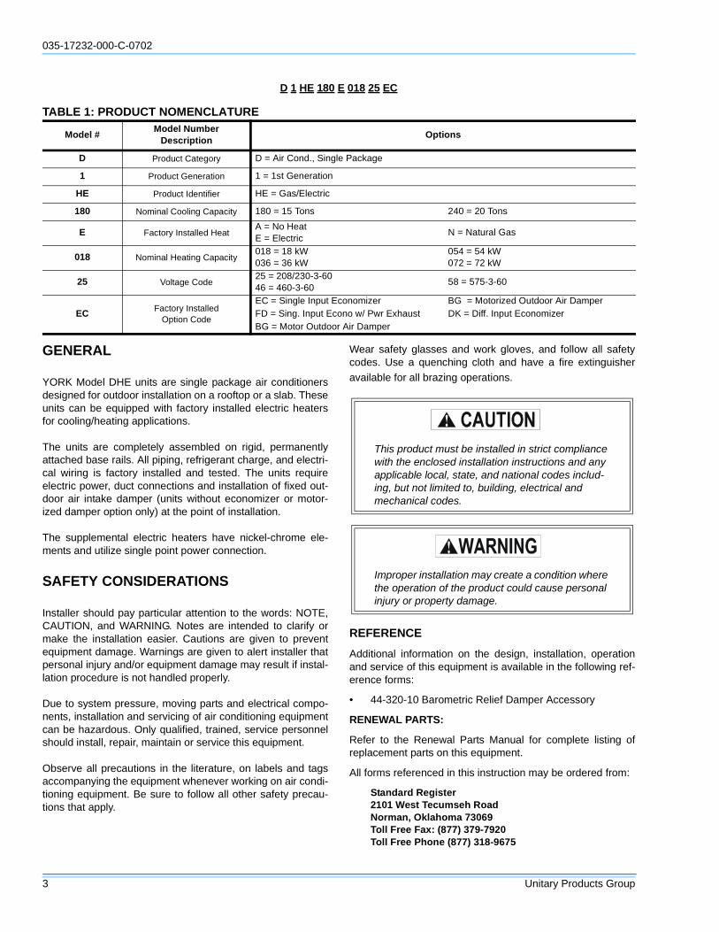
TABLE 1: PRODUCT NOMENCLATURE
Model #Model Number
DescriptionOptions
D Product Category D = Air Cond., Single Package
1 Product Generation 1 = 1st Generation
HE Product Identifier HE = Gas/Electric
180 Nominal Cooling Capacity 180 = 15 Tons 240 = 20 Tons
E Factory Installed HeatA = No HeatE = Electric
N = Natural Gas
018 Nominal Heating Capacity018 = 18 kW036 = 36 kW
054 = 54 kW072 = 72 kW
25 Voltage Code25 = 208/230-3-6046 = 460-3-60
58 = 575-3-60
EC Factory InstalledOption Code
EC = Single Input Economizer BG = Motorized Outdoor Air DamperFD = Sing. Input Econo w/ Pwr Exhaust DK = Diff. Input EconomizerBG = Motor Outdoor Air Damper
This product must be installed in strict compliancewith the enclosed installation instructions and anyapplicable local, state, and national codes includ-ing, but not limited to, building, electrical andmechanical codes.
Improper installation may create a condition wherethe operation of the product could cause personalinjury or property damage.
035-17232-000-C-0702
Unitary Products Group 4
AGENCY APPROVALS
Design certified by ETL & CGA as follows:
1. For use as a central cooling only unit with or without sup-plemental electric heat.
2. For outdoor installation only.
3. For installation on combustible material.
INSPECTION
As soon as a unit is received, it should be inspected for possi-ble damage during transit. If damage is evident, the extent ofthe damage should be noted on the carrier's freight bill. Aseparate request for inspection by the carrier's agent shouldbe made in writing. Refer to Form 50.15-NM for additionalinformation.
INSTALLATION
LIMITATIONS
These units must be installed in accordance with the follow-ing national and local safety codes:
In United States:
1. National Electrical Code ANSI/NFPA No. 70.
2. Local electric utility requirements.
In Canada:
1. Current Canadian Electrical Code CSA C22.1.
2. Local electrical codes.
Refer to Table 2 for Unit Application Data and to Table 4 forElectric Heater Application Data.
If components are to be added to a unit to meet local codes,they are to be installed at the dealer's and/or the customer'sexpense.
Size of unit for proposed installation should be based on heatloss/heat gain calculation made according to the methods ofthe Air Conditioning Contractors of America (ACCA).
LOCATION
Use the following guidelines to select a suitable location forthese units.
1. Unit is designed for outdoor installation only.
2. Outdoor coils must have an unlimited supply of air.Where a choice of location is possible, position the uniton either north or east side of building.
3. For ground level installation, use a level concrete slabwith a minimum thickness of four inches. The length andwidth should be at least six inches greater than the unitbase rail dimensions. Do not tie slab to the building foun-dation.
4. Roof structures must be able to support the weight of theunit and its options and/or accessories. Unit must beinstalled on a solid level roof curb or appropriate angleiron frame.
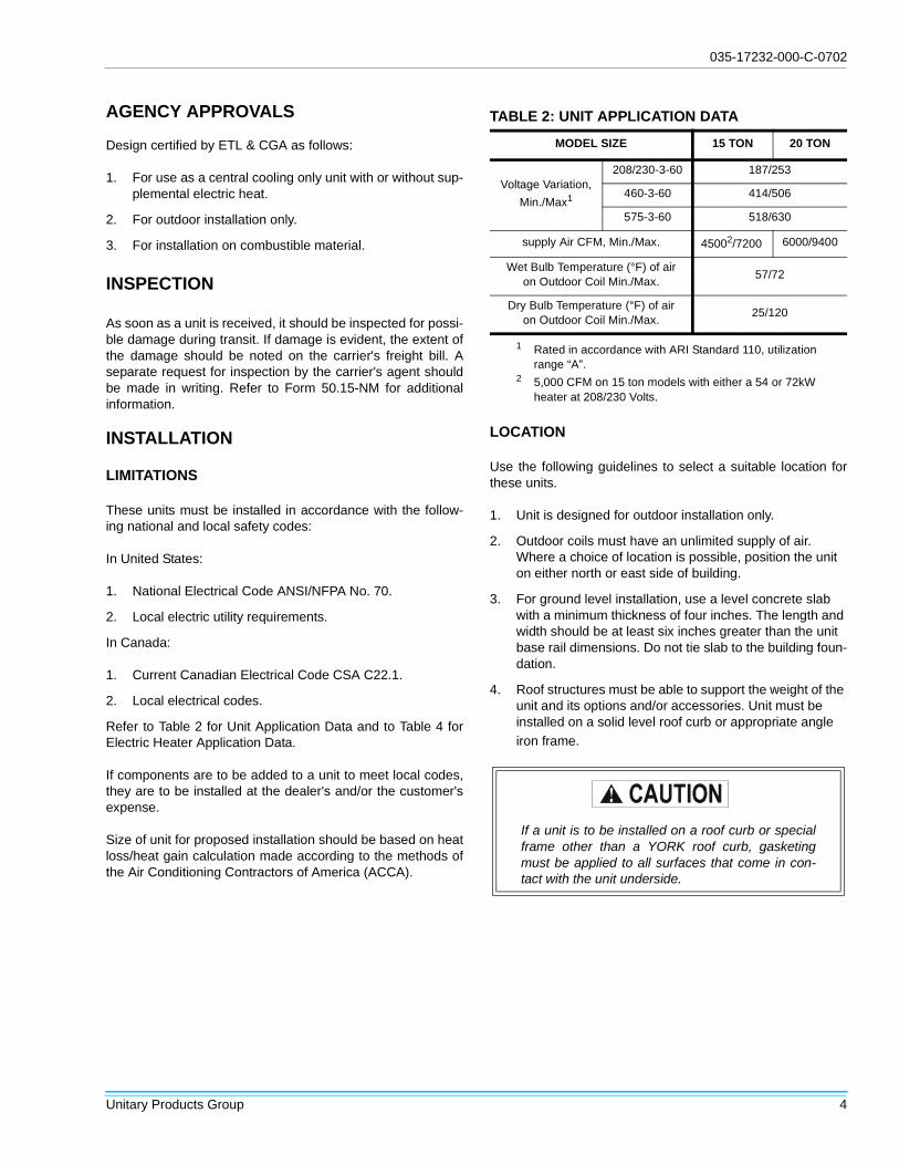
TABLE 2: UNIT APPLICATION DATA
MODEL SIZE 15 TON 20 TON
Voltage Variation,
Min./Max1
1 Rated in accordance with ARI Standard 110, utilizationrange “A”.
208/230-3-60 187/253
460-3-60 414/506
575-3-60 518/630
supply Air CFM, Min./Max. 45002/7200
2 5,000 CFM on 15 ton models with either a 54 or 72kWheater at 208/230 Volts.
6000/9400
Wet Bulb Temperature (°F) of airon Outdoor Coil Min./Max.
57/72
Dry Bulb Temperature (°F) of airon Outdoor Coil Min./Max.
25/120
If a unit is to be installed on a roof curb or specialframe other than a YORK roof curb, gasketingmust be applied to all surfaces that come in con-tact with the unit underside.

035-17232-000-C-0702
5 Unitary Products Group
5. Maintain level tolerance to 1/2" maximum across theentire length or width of the unit.
RIGGING AND HANDLING
Exercise care when moving the unit. Do not remove anypackaging until the unit is near the place of installation. Rigthe unit by attaching chain or cable slings to the round liftingholes provided in the base rails. Spreaders, whose lengthexceeds the larger dimension across the unit, MUST be usedacross the top of the unit. Refer to Figure 1.
Units may also be moved or lifted with a forklift, from the frontor rear only, providing that an accessory skid is used.
Refer to Table 5 for unit weights and to Figure 2 for approxi-mate center of gravity.
CLEARANCES
All units require certain clearances for proper operation andservice. Refer to Table 6 for the clearances required for com-bustible construction, servicing, and proper unit operation.
DUCTWORK
Ductwork should be designed and sized according to themethods in Manual Q of the Air Conditioning Contractors ofAmerica (ACCA).
A closed return duct system shall be used. This shall not pre-clude use of economizers or outdoor fresh air intake. Thesupply and return air duct connections at the unit should bemade with flexible joints to minimize transmission of noise.
The supply and return air duct systems should be designedfor the CFM and static requirements of the job. They shouldNOT be sized to match the dimensions of the duct connec-tions on the unit.
Outdoor ductwork must be insulated and waterproofed.
Refer to Figure 7 and 9 for information concerning side andbottom supply and return air duct openings.
FIXED OUTDOOR AIR INTAKE DAMPER
This damper is shipped inside the return air compartment. Itis completely assembled and ready for installation. A damperbaffle inside the hood is adjustable to provide variableamounts of outdoor air intake on units that are not providedwith an economizer or a motorized damper option. Refer toFigure 3.
Gasketing and mounting screws are provided in a parts bagattached to the hood assembly. Apply gasketing to the threeflange surfaces on the hood prior to installing the hood.Extend gasketing 1/4" beyond the top and bottom of the twoside flanges to insure adequate sealing.
FIGURE 1 : TYPICAL RIGGING
Length of forks must be a minimum of 90”.
FIGURE 2 : CENTER OF GRAVITY
� � � � � � � � � � � � � � � � � � � � � � �� � � � � � � � � � � � �� � � � � � � � � � � � � � � � � � � � � � � � � � � � � �� � � � � � � � � � � � � � � � � � � �
� � � � � � �� � � �
� � � � � � � �
Do not permit overhanging structures or shrubs toobstruct outdoor air discharge outlet.
When fastening ductwork to side duct flanges onthe unit, insert screws through duct flanges only.DO NOT insert screws through casing.

035-17232-000-C-0702
Unitary Products Group 6
Adjusting the damper to the desired air flow may be donebefore mounting the hood into position or (after installation)by removing the front hood panel or the screen on the bottomof the hood. Damper baffle in position 1 will allow approxi-mately 10% recirculated air flow, position 2 approximately15% and to allow approximately 25%, remove the damperbaffle.
On units with bottom return air applications, install thedamper assembly over the opening in the side return airaccess panel. Remove and discard the opening cover andthe covering over the hood mounting holes (used for ship-ping) before installing. Secure with the screws provided.
On units with side return air applications, install the damperassembly on the return air ductwork as close to the unit aspossible. Cut an opening 16" high by 18" wide in the ductworkto accommodate the damper. Using the holes in the hoodflanges as a template, drill 9/64" dia. (#26 drill) holes into theductwork and secure with the screws provided.
CONDENSATE DRAIN
Plumbing must conform to local codes. Use a sealing com-pound on male pipe threads. Install a condensate drain linefrom the 1" NPT female connection on the unit to an opendrain.
An alternate drain connection (1" NPT female coupling) isprovided inboard on the same centerline as the exterior loca-tion.
NOTE: The condensate drain operates in a negative pres-sure are in the cabinet. The condensate drain line MUST betrapped to provide proper drainage. See Figure 4.
COMPRESSORS
Units are shipped with compressor mountings factory-adjusted and ready for operation.
FILTERS
Two-inch filters are supplied with each unit. Filters mustalways be installed ahead of the indoor coil and must be keptclean or replaced with same size and type. Dirty filters willreduce the capacity of the unit and will result in frosted coilsor safety shutdown. Minimum filter area and required sizesare shown in Table 5.
SERVICE ACCESS
Access to all serviceable components is provided by the fol-lowing removable panels:
• Compressor compartment
• Electric Heat compartment
• Side Supply & Return Air compartments (Two panels)
• Blower compartment (Three panels)
• Main control box
• Filter compartment
• Outdoor Air compartment (Two panels)
If outdoor air intake will not be required on unitswith bottom return air applications, the damperassembly should still be mounted on the sidereturn air access panel, per the instructions above,to ensure moisture is not drawn into the unit duringoperation. The covering over the mounting holesonly need be removed. Do not remove the openingcover.
FIGURE 3 : FIXED OUTDOOR AIR DAMPER
FIGURE 4 : RECOMMENDED DRAIN PIPING
Do Not loosen compressor mounting bolts.

035-17232-000-C-0702
7 Unitary Products Group
Refer to Figure 7, 8 and 9 for location of these access panels. THERMOSTAT
The room thermostat should be located on an inside wallapproximately 56" above the floor where it will not be subjectto drafts, sun exposure or heat from electrical fixtures orappliances. Follow manufacturer's instructions enclosed withthermostat for general installation procedure. Color codedinsulated wires (#18 AWG) should be used to connect ther-mostat to unit.
FIGURE 5 : TYPICAL FIELD WIRING
�
� �
� �
�
�
� �
� �
� �
� �
�
�
� �
� �
� �
� �
� �
� �
� �
� �
�
�� �
� �
� �
� �
� �
�
� � �
� � �
� � �
� �
� �
�
�
�
�
�
�
� �
� �
� �
� �
�
�
� �
� �
� �
� �
� �
� �
�
� �
� �
� �
� �
�
�
� �
� �
� �
� � � � � �
� � � � � � � � � � � � � � � ! � � � � � � � � �
� " # $ % & ' ( ) $ * & ' + & , - - , . " # % / # & - ' 0 % , % � � � ! � � � 1 ) ( $ " 2 3 # 0 0 2 . . , 0 # 4 5 � � # & - ) ( , " . " ' $ 6 � � 7 " ' $ , % # 3 ' ( & # " , 8 . ' , & 3 ) ( � � 7 9 ' " % 0 # $ % ) ' ( ' : % / # 2 ( ) % $ ' ( % & ' " . ' ; 5 � � # $ ' ( 3 0 % , + # / # , % ) ( + ) 0 ( ' % & # < 2 ) & # 3 ' ( 2 ( ) % 0 = ) % / , 0 ) ( + " # 0 % , + # # " # $ % & ) $ / # , % # & 5 � � # & - ) ( , " 0 � � , ( 3 � � * & ' 9 ) 3 # , & # " , 8 ' 2 % * 2 % % ' $ " ' 0 # % / # ' 2 % 3 ' ' & # $ ' ( ' - ) > # & 3 , - * # & 0 = / # ( % / # % / # & - ' 0 % , % 0 = ) % $ / # 0 % ' % / # 0 # % 7 . , $ 6 * ' 0 ) % ) ' ( 5 � � � � � � � � � � � � � � � � � � � � � � � � � � � � � � � � � � � � � � � � � � � � � � � � � � � � � � � � � � � � � � � � � � � � � � � �
� � � � � � � � � � � � � � � � � � � � � � � � � � � � � � � � �
� � � � � � � � �
� # : # & % ' % / # � � � � � � � � � � � � % , . " # 0 % ' 0 ) > # % / # * ' = # & = ) & ) ( + � % / # : 2 0 # 0 , ( 3 % / # 3 ) 0 $ ' ( ( # $ % 0 = ) % $ / 5
� � � � � � � � � � � � � � � �
� � � � � � � � � � � 1 � � � � � � � � � � � � � � � 4
� � � � � � � � � � � � � � � � � �
� � � � � � � ? � � � � � � 1 � � � � � � � � � � � � � � � 4
� � � � � � � � � � � � � � � � � �
� � � � � � � � � � �
� � � � � � � � � � � � � � � � � �
� � � � ' " % � / # & - ' 0 % , % � � � � ! � � � ' & � � � � ! � @ � � 1 = ) % / � 2 . . , 0 # � � � ! � � � 4 5 � � # & - ) ( , " 0 % & ) * � � 7 " ' $ , % # 3 ' ( & # " , 8 . ' , & 3 ) ( � � 7 9 ' " % 0 # $ % ) ' ( ' : % / # 2 ( ) % $ ' ( % & ' " . ' ; 5 � � # $ ' ( 3 0 % , + # / # , % ) ( + ) 0 ( ' % & # < 2 ) & # 3 ' ( 2 ( ) % 0 = ) % / , 0 ) ( + " # 0 % , + # # " # $ % & ) $ / # , % # & 5
� � � � � � � � � � � � � � � � � �
� � � � � � � � � � � � � � � � � �
� � � � � � � � � � � 1 � � � � � � � � � � � � � � � 4
� � � � ' " % � / # & - ' 0 % , % � � � � ! � � � � ' & � � � � ! � @ � � 1 = ) % / � 2 . . , 0 # � � � ! � � � 4 5 � # & - ) ( , " . " ' $ 6 � � 7 " ' $ , % # 3 ' ( & # " , 8 . ' , & 3 ) ( � � 7 9 ' " % 0 # $ % ) ' ( ' : % / # 2 ( ) % $ ' ( % & ' " . ' ; 5
� � � � � � � � � � � � � � � �
� � � � � � � � � � � � � � � � � �
� � � � � � � � � � � � � � � �
� � � � � � � � � �
� � � A � � � �
� � � A � � � �
� � � A � � � �
Make sure that all screws and panel latches arereplaced and properly positioned on the unit tomaintain an air-tight seal.

035-17232-000-C-0702
Unitary Products Group 8
POWER AND CONTROL WIRING
Field wiring to the unit must conform to provisions of theNational Electrical Code, ANSI / NFPA No. 70 (in U.S.A.),current Canadian Electric Code (CEC) CSA C22.1 (in Can-ada) and/or local ordinances. The unit must be electricallygrounded in accordance with NEC and CEC (as specifiedabove) and/or local codes. Voltage tolerances which must bemaintained at the compressor terminals during starting andrunning conditions are indicated on the unit rating plate andTable 2.
The internal wiring harness furnished with this unit is an inte-gral part of a ETL and CGA design certified unit. Field alter-ation to comply with electrical codes should not be required.
A fused disconnect switch should be field provided for theunit. The switch must be separate from all other circuits. Wireentry at knockout openings require conduit fittings to complywith CEC (in Canada), NEC (in U.S.A.) and/or local codes.Refer to Figure 7 for installation location. If any of the wiresupplied with the unit must be replaced, replacement wiremust be of the type shown on the wiring diagram and thesame minimum gauge as the replaced wire.
Electrical line must be sized properly to carry the load. Eachunit must be wired with a separate branch circuit fed directlyfrom the meter panel and properly fused.
Refer to Figure 5 for typical field wiring and to the appropriateunit wiring diagram for control circuit and power wiring infor-mation.
OPTIONAL ELECTRIC HEATERS
The factory installed heaters are wired for single point powersupply. Power supply need only be brought into the singlepoint terminal block and thermostat wiring to the low voltageterminal strip located in the upper portion of the unit controlbox.
These ETL and CGA approved heaters are located within thecentral compartment of the unit with the heater elementsextending into the supply air chamber. Refer to Figure 7 foraccess panel location.
OPTIONAL ECONOMIZER/MOTORIZED DAMPERRAIN HOOD
The instruction for the optional economizer/motorizeddamper rain hood can be found in form 44-320-2. Use theseinstructions when field assembling an economizer rain hoodonto a unit. The outdoor and return air dampers, the damperactuator, the damper linkage, the outdoor and return airdivider baffles, and all the control sensors are factorymounted as part of the factory installed economizer option.
ENTHALPY SET POINT ADJUSTMENT
Remove the economizer access panel from the unit to checkthe following adjustments. Loosen but do not remove the two
panel latches.
1. The enthalpy set point may now be set by selecting thedesired setpoint shown in Figure 6. Adjust as follows:
• For a single enthalpy operation, carefully turn the setpoint adjusting screw to the A, B, C or D setting corre-sponding to the lettered curve.
TABLE 3: CONTROL WIRE SIZES1
1 Total wire length is from unit to room thermostat, andback to unit.
Wire Size2
2 Solid, Class II copper wire.
22 20 19 18 16
40 120 150 190 305
Max. Wire Length3 Feet
3 Total Wire length is from unit to room thermostat, andback to unit.
When connecting electrical power and control wir-ing to the unit, waterproof type connectors MUSTBE USED so that water or moisture cannot bedrawn into the unit during normal operation. Theabove waterproofing conditions will also applywhen installing a field-supplied disconnect switch.
TABLE 4: ELECTRIC HEATER APPLICATION DATA
NominalHeater Size (kW.)
Voltage 3 Phase60 Hz
Min. CFM (Unit Size)
15 Ton 20 Ton
18 208/230,460,575 4500 6000
36 208/230,460,575 4500 6000
54208/230 5000
6000460/575 4500
72208/230 5000
6000460/575 4500
Extreme care must be exercised in turning boththe setpoint and minimum position adjustingscrews to prevent twisting them off.

035-17232-000-C-0702
9 Unitary Products Group
• For a dual enthalpy operation, carefully turn the set pointadjusting screw fully clockwise past the D setting.
2. To check that the damper blades move smoothly withoutbinding, carefully turn the minimum position adjustingscrew fully clockwise and then energize and de-energizeterminals R to G. With terminals R to G energized, turnthe minimum position screw counterclockwise until thedesired minimum position has been attained.
3. Replace the economizer access panel. Reposition thetwo latches horizontally and retighten the screws.
POWER EXHAUST/BAROMETRIC RELIEF DAMPERAND RAIN HOOD OPTION
The instructions for the power exhaust/barometric reliefdamper and rain hood can be found in form 44-320-10. Theexhaust fan, all supporting brackets, angles, and the wiringare factory installed as part of the power exhaust option.
All of the components, including the dampers, hardware, andmounting instructions are shipped in a single package exter-nal from the unit. The hood must be field assembled andinstalled.
Power exhaust is not available as a field installed option.
FIGURE 6 : ENTHALPY SETPOINT ADJUSTMENT

035-17232-000-C-0702
Unitary Products Group 10
NOTE: A one-inch clearance must be provided between anycombustible material and the supply air ductwork for a dis-tance of 3 feet from the unit.
NOTE: The products of combustion must not be allowed toaccumulate within a confined space and recirculate.
NOTE: Unit and ductwork are approved for zero clearance tocombustible materials when equipped with electric heat.
DUCT COVERS - Units are shipped with the bottom ductopenings covered. An accessory flange kit is available forconnecting side ducts.
For bottom duct applications:
1. Remove the side panels from the supply and return aircompartments to gain access to the bottom supply andreturn air duct covers.
2. Remove and discard the bottom duct covers. (Ductopenings are closed with sheet metal covers exceptwhen the unit includes a power exhaust option. The cov-ering consists of a heavy black paper composition.)
3. Replace the side supply and return air compartment pan-els.
For side duct applications:
1. Replace the side panels on the supply and return aircompartments with the accessory flange kit panels.
2. Connect ductwork to the duct flanges on the rear of theunit.
TABLE 5: PHYSICAL DATA
MODELSDHG/DHE
180 240
EVAPORATORBLOWER
Centrifugal Blower (Dia. x Wd. in.) 15 x 15 18 x 15
Fan Motor HP 5 7.5
EVAPORATORCOIL
Rows Deep 4 4
Fins Per Inch 13.5 13.5
Face Area (Sq. Ft. 15.5 20.0
CONDENSERFANS
(Two Per Unit)
Propeller Dia. (in.) (Each) 30 30
Fan Motor Hp (Each) 1 1
Nom. CFM (Each) 5765 7000
CONDENSERCOILS
(Two Per Unit)
Rows Deep (Each) 2 3
Fins Per Inch (Each) 13 15
Face Area (Sq. Ft.) (Total) 36.0 43.3
COMPRESSOR(Qty. Per Unit)
10-Ton Tandem Hermetic Recip. 11 2
5-Ton Hermetic Recip. 1 -
AIRFILTERS
Quantity Per Unit (16” X 20” X 2”) - 4
Quantity Per Unit (16” X 25” X 2”) - 4
Quantity Per Unit (18” X 24” X 2”) 5 -
Total Face Area (sq. ft.) 15.0 20.0
CHARGERefrigerent 22
(lbs./oz.)
System #1 29/9 23
System #2 14/8 23/12
WEIGHT (lbs)
BASICUNIT
DHE (Cooling Only) 1900 2100
OPTIONS
Economizer 160
Economizer withPower Exhaust
245
Motorized Damper 150
Electric Heater
18kW 25
36kW 30
54kW 35
72kW 40
ACCY.
Roof Curb 175 185
Barometric Damper 45 45
Wood Skid 220 220
1This compressor will be energized first.
TABLE 6: MINIMUM CLEARANCESLOCATION CLEARANCES
Front 36”
Back24” (Less Economizer)36” (With Economizer
Left Side (Filter Access)24” (Less Economizer)36” (With Economizer)
Right Side (Cond. Coil) 36”
Below Unit1
1 Units may be installed on combustible floors madefrom wood or class A, B, or C roof covering material.
0”
Above Unit2
2 Units must be installed outdoors. Overhanging struc-tures or shrubs should not obstruct condenser air dis-charge outlet.
72” With 36” MaximumHorizontal Overhang (ForCondenser Air Discharge)
TABLE 7: UTILITIES ENTRY
HOLEOPENING SIZE
(DIA.)USED FOR
A1-1/8” KO
Control WiringFront
3/4” NPS (Fem.) Bottom
B3-5/8” KO
Power WiringFront
3” NPS (Fem.) Bottom

035-17232-000-C-0702
11 Unitary Products Group
FIGURE 7 : UNIT DIMENSIONS DHE/DHG180 & 240 (FRONT VIEW)
RETURN AIR
SUPPLYAIR
BOTTOM SUPPLYAND RETURN
AIR OPENINGS(See Note)
(B)POWER WIRINGENTRY
(A)CONTROL WIRING ENTRYNOTE:
For curb mounted units, refer to the curb hangerdimensions of the curb for the proper size of thesupply and return air duct connections.
UNIT BASE WITH RAILSShown separately to illustrateBottom Duct openings, Powerand Gas Piping Connection locations
12-1/2"
9-1/4"
8-1/8"
9-3/4"
3-3/4"
(B)POWER WIRINGENTRY
(A)CONTROL WIRING ENTRY
CONDENSERCOILS
OPTIONAL COILGUARD KIT
COMPRESSORACCESS
ECONOMIZER / MOTORIZED DAMPER,FIXED OUTDOOR INTAKE AIR ANDPOWER EXHAUST RAIN HOODS(See detail "Y")
FIELD-SUPPLIEDDISCONNECT SWITCHLOCATION
BLOWERACCESS
BLOWER MOTORACCESS
BLOWERCOMPARTMENTACCESS(Auxiliary)
DOT PLUG(For pressureDrop Reading)
FRONTVIEW
CONTROL BOXACCESS
21"
5"
9-3/4"
11-1/2"
2-3/4" 21-1/2"
33"
35"
5-7/8"
46-5/8"
7-1/8"
6-3/8"
VENT AIROUTLETHOODS
COMBUSTIONAIR INLETHOOD
GAS HEATACCESS
(C)GAS SUPPLY ENTRY
46-5/8"
11-1/8"
(D)GAS SUPPLYENTRY
RETURN AIR
SUPPLY AIR
OUTDOOR AIR
OUTDOOR AIR(Economizer)
92"
24-1/4" (15 Ton)35-1/4" (20 Ton)
125-1/4" (15 Ton)136-1/4" (20 Ton)
48-5/8" (15 Ton)52-5/8" (20 Ton)
All dimensions are in inches. They aresubject to change without notice. Certi-fied dimensions will be provided uponrequest.
FIGURE 8 : UNIT DIMENSIONS DHE/DHG180 & 240 (RAINHOOD)
� � � � � � � � �� � � � � � � � � �
� � � � � � � � � �� � � � � � � �1 ' ( � # % 2 & ( � ) & � ' - * , & % - # ( % 4
� � � � � � B �� � � � � � B �� � � � �� � � � � � � �1 ' ( � 2 % 3 ' ' & � ) & � ' - * , & % - # ( % 4
� � � � � � B � ? � � � � � � B � � � � � �� � � � � � � � � � � � � � � � � � � � � �
� � � �� � � � � � � � � �� � � � � � � � �1 " ' $ , % # 3 ' (� # % 2 & ( � ) &� ' - * , & % - # ( % 4
� C � � � � � � � � � � � � � �1 � 2 0 % . # % & , * * # 3 4
� � � � � � � � � � �� � � � � C � C
� � � � � � � � � � � � � � � � �
� D C
D D 7 � ? � CE � C� D 7 � ? � C
@ C
� � 7 � ? � C
� D 7 � ? F C
� C

035-17232-000-C-0702
Unitary Products Group 12
FIGURE 9 : UNIT DIMENSIONS DHE/DHG180 & 240 (REAR VIEW)
� � � � �� � �
� � � � � � �� � �
� � � � � �� � �
� � � � � � � � � � � �
� � � � � � � � �� � � � �
� � � � � � � � �� � � � �
� � � � � � � � � � � � �
� � � � � � � �� � � � �
� � � � � � � � � �� � � � � � � � � �� � � � �
� C � � � � � � � � � � � 5 � � � � �� � � � � � � � �
� � � � �� � � � �
� � � � � � �1 � ' & * & # 0 0 2 & #3 & ' * & # , 3 ) ( + 4
� � � � � � � � �� � � � � �
� 7 � ? � C
� F 7 @ ? F C 1 � @ � ' ( 0 4� E 7 @ ? F C 1 � � ' ( 0 4
� ! 7 � ? � C
@ 7 � ? F C
� F 7 @ ? F C
@ 7 � ? � C
� 7 � ? F C
� � �� � �
OUTDOOR AIR PANEL SIZES
15 TON UNITS 21-1/2” X 43”
20 TON UNITS 32-1/2” X 43”

035-17232-000-C-0702
13 Unitary Products Group
TABLE 8: DHE 15 TON SUPPLY AIR BLOWER PERFORMANCE
DHE180 - BOTTOM DUCT CONNECTIONS1, 2
BLOWERSPEED,(RPM)
MOTORPULLEY(TURNS
OPEN)3
CFM
4500 5250 6000 6750 7200
ESP4 BHP KW ESP4 BHP KW ESP4 BHP KW ESP4 BHP KW ESP4 BHP KW
208 VOLT AND STANDARD DRIVE
850 6.05 0.9 2.4 2.2 0.7 3.0 2.7 0.5 3.2 2.9 - - - - - -
870 5.5 1.0 2.5 2.3 0.8 3.1 2.8 0.6 3.5 3.1 0.2 4.1 3.7 - - -
915 4.5 1.1 2.6 2.4 0.9 3.4 3.0 0.7 3.7 3.3 0.3 4.4 3.9 0.2 4.5 4.0
965 3.5 1.2 2.9 2.6 1.0 3.6 3.2 0.8 4.0 3.6 0.5 4.7 4.2 0.4 4.9 4.4
980 3.0 1.3 3.0 2.7 1.1 3.7 3.3 0.9 4.1 3.7 0.6 4.8 4.3 0.5 5.1 4.6
1010 2.0 1.4 3.1 2.8 1.2 3.8 3.4 1.0 4.2 3.8 0.7 5.0 4.5 0.6 5.4 4.8
1040 1.0 1.5 3.2 2.9 1.3 3.9 3.5 1.1 4.5 4.0 0.9 5.2 4.7 0.7 5.7 5.1
208 VOLT AND HIGH SPEED DRIVE ACCESSORY
965 6.0 1.2 2.9 2.6 1.0 3.6 3.2 0.8 4.0 3.6 0.5 4.7 4.2 0.4 5.0 4.4
980 5.5 1.3 3.0 2.7 1.1 3.7 3.3 0.9 4.1 3.7 0.6 4.8 4.3 0.5 5.1 4.6
1025 4.5 1.5 3.2 2.9 1.3 3.9 3.5 1.1 4.5 4.0 0.8 5.1 4.6 0.7 5.6 5.0
1065 3.5 1.6 3.4 3.0 1.4 4.0 3.6 1.2 4.7 4.2 1.0 5.5 4.9 - - -
1095 3.0 1.7 3.5 3.1 1.5 4.2 3.8 1.3 4.9 4.4 1.2 5.7 5.1 - - -
1130 2.0 1.9 3.7 3.3 1.7 4.5 4.0 1.5 5.1 4.6 - - - - - -
1170 1.0 2.1 3.9 3.5 2.0 4.7 4.2 1.8 5.5 4.9 - - - - - -
230/460/575 VOLT AND STANDARD DRIVE
870 6.05 1.0 2.4 2.2 0.8 3.1 2.8 0.6 3.5 3.1 0.2 4.1 3.7 - - -
915 5.0 1.1 2.6 2.4 0.9 3.3 3.0 0.7 3.7 3.3 0.3 4.4 3.9 0.2 4.5 4.0
965 4.0 1.2 2.9 2.6 1.0 3.6 3.2 0.8 4.0 3.6 0.5 4.7 4.2 0.4 5.0 4.4
980 3.5 1.3 3.0 2.7 1.1 3.7 3.3 0.9 4.1 3.7 0.6 4.8 4.3 0.5 5.1 4.6
1040 2.0 1.5 3.2 2.9 1.3 3.9 3.5 1.1 4.5 4.0 0.9 5.3 4.7 0.7 5.7 5.1
1065 1.0 1.6 3.3 3.0 1.4 4.0 3.6 1.2 4.7 4.2 1.0 5.5 4.9 - - -
230/460/575 VOLT AND HIGH SPEED DRIVE ACCESSORY
980 6.0 1.3 2.9 2.6 1.1 3.7 3.3 0.9 4.1 3.7 0.6 4.8 4.3 0.5 5.1 4.6
1040 4.5 1.5 3.2 2.9 1.3 3.9 3.5 1.1 4.5 4.0 0.9 5.3 4.7 0.7 5.7 5.1
1065 4.0 1.6 3.4 3.0 1.4 4.0 3.6 1.2 4.7 4.2 1.0 5.5 4.9 - - -
1095 3.5 1.7 3.5 3.1 1.5 4.2 3.8 1.3 4.9 4.4 1.2 5.7 5.1 - - -
1130 2.5 1.9 3.7 3.3 1.7 4.5 4.0 1.5 5.1 4.6 - - - - - -
1170 1.5 2.1 3.9 3.5 2.0 4.7 4.2 1.8 5.5 4.9 - - - - - -
1190 1.0 2.2 4.0 3.6 2.1 4.8 4.3 2.0 5.7 5.1 - - - - - -
1 Blower performance includes a gas-fired heat exchanger, fixed outdoor air, 2” T/A filters and a dry evaporator coil.2 Refer to the Table 10 for static resistances.3 DO NOT close the pulley below one turn open.4 ESP = External Static Pressure available for the supply and return air duct system. All internal unit resistances have been
deducted from the total static pressure of the blower.5 The Factory Setting.
035-17232-000-C-0702
Unitary Products Group 14
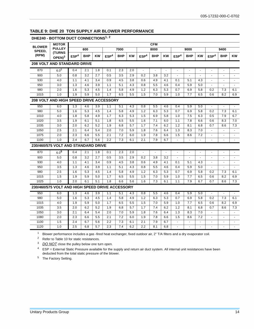
TABLE 9: DHE 20 TON SUPPLY AIR BLOWER PERFORMANCE
DHE240 - BOTTOM DUCT CONNECTIONS1, 2
BLOWERSPEED,(RPM)
MOTORPULLEY(TURNS
OPEN)3
CFM
600 7000 8000 9000 9400
ESP4 BHP KW ESP4 BHP KW ESP4 BHP KW ESP4 BHP KW ESP4 BHP KW
208 VOLT AND STANDARD DRIVE
870 6.05 0.4 2.1 1.8 0.1 2.3 2.0 - - - - - - - - -
900 5.0 0.8 3.2 2.7 0.5 3.5 2.9 0.2 3.8 3.2 - - - - - -
930 4.0 1.1 4.1 3.4 0.9 4.5 3.8 0.6 4.9 4.1 0.1 5.1 4.3 - - -
950 3.0 1.3 4.6 3.9 1.1 5.1 4.3 0.8 5.5 4.6 0.4 5.9 5.0 - - -
980 2.0 1.6 5.3 4.5 1.4 5.8 4.9 1.2 6.3 5.3 0.7 6.9 5.8 0.2 7.3 6.1
1015 1.0 1.9 5.9 5.0 1.7 6.5 5.5 1.5 7.0 5.9 1.0 7.7 6.5 0.6 8.2 6.9
208 VOLT AND HIGH SPEED DRIVE ACCESSORY
950 6.0 1.3 4.6 3.9 1.1 5.1 4.3 0.8 5.5 4.6 0.4 5.9 5.0 - - -
980 5.0 1.6 5.3 4.5 1.4 5.8 4.9 1.2 6.3 5.3 0.7 6.9 5.8 0.2 7.3 6.1
1010 4.0 1.8 5.8 4.9 1.7 6.3 5.3 1.5 6.9 5.8 1.0 7.5 6.3 0.5 7.9 6.7
1020 3.5 1.9 6.1 5.1 1.8 6.5 5.5 1.6 7.1 6.0 1.1 7.8 6.6 0.6 8.3 7.0
1035 3.0 2.0 6.2 5.2 1.9 6.8 5.7 1.7 7.4 6.2 1.2 8.1 6.8 0.7 8.6 7.3
1050 2.5 2.1 6.4 5.4 2.0 7.0 5.9 1.8 7.6 6.4 1.3 8.3 7.0 - - -
1075 2.0 2.3 6.6 5.5 2.1 7.2 6.0 1.9 7.8 6.6 1.5 8.6 7.2 - - -
1100 1.0 2.4 6.7 5.6 2.2 7.3 6.1 2.1 7.9 6.7 - - - - - -
230/460/575 VOLT AND STANDARD DRIVE
870 6.05 0.4 2.1 1.8 0.1 2.3 2.0 - - - - - - - - -
900 5.0 0.8 3.2 2.7 0.5 3.5 2.9 0.2 3.8 3.2 - - - - - -
930 4.0 1.1 4.1 3.4 0.9 4.5 3.8 0.6 4.9 4.1 0.1 5.1 4.3 - - -
950 3.5 1.3 4.6 3.9 1.1 5.1 4.3 0.8 5.5 4.6 0.4 5.9 5.0 - - -
980 2.5 1.6 5.3 4.5 1.4 5.8 4.9 1.2 6.3 5.3 0.7 6.9 5.8 0.2 7.3 6.1
1015 1.5 1.9 5.9 5.0 1.7 6.5 5.5 1.5 7.0 5.9 1.0 7.7 6.5 0.6 8.2 6.9
1025 1.0 2.0 6.1 5.1 1.8 6.6 5.6 1.6 7.3 6.1 1.1 7.9 6.7 0.7 8.6 7.3
230/460/575 VOLT AND HIGH SPEED DRIVE ACCESSORY
950 6.0 1.3 4.6 3.9 1.1 5.1 4.3 0.8 5.5 4.6 0.4 5.9 5.0 - - -
980 5.0 1.6 5.3 4.5 1.4 5.8 4.9 1.2 6.3 5.3 0.7 6.9 5.8 0.2 7.3 6.1
1015 4.0 1.9 5.9 5.0 1.7 6.5 5.5 1.5 7.0 5.9 1.0 7.7 6.5 0.6 8.2 6.9
1035 3.5 2.0 6.2 5.2 1.9 6.8 5.7 1.7 7.4 6.2 1.2 8.1 6.8 0.7 8.6 7.3
1050 3.0 2.1 6.4 5.4 2.0 7.0 5.9 1.8 7.6 6.4 1.3 8.3 7.0 - - -
1080 2.0 2.3 6.6 5.5 2.1 7.2 6.0 1.9 7.8 6.6 1.5 8.6 7.2 - - -
1100 1.5 2.4 6.7 5.6 2.2 7.3 6.1 2.1 7.9 6.7 - - - - - -
1120 1.0 2.5 6.8 5.7 2.3 7.4 6.2 2.2 8.1 6.8 - - - - - -
1 Blower performance includes a gas -fired heat exchanger, fixed outdoor air, 2” T/A filters and a dry evaporator coil.2 Refer to Table 10 for static resistances.3 DO NOT close the pulley below one turn open.4 ESP = External Static Pressure available for the supply and return air duct system. All internal unit resistances have been
deducted from the total static pressure of the blower.5 The Factory Setting.

035-17232-000-C-0702
15 Unitary Products Group
TABLE 10: STATIC RESISTANCES1
DESCRIPTION
RESISTANCE, IWG
CFM
15 TON 20 TON
4500 5765 7200 6000 7000 9400
WET COIL 0.1 0.1 0.1 0.1 0.1 0.1
ELECTRIC HEAT OPTIONS(DHE models only)
18kW 0.1 0.1 0.1 0.1 0.1 0.1
36kW 0.1 0.2 0.3 0.1 0.2 0.3
54kW 0.2 0.3 0.4 0.2 0.3 0.4
72kW 0.2 0.4 0.6 0.2 0.4 0.6
EXONOMIZER OPTION 0.1 0.1 0.1 0.1 0.1 0.1
HORIZONTAL DUCT CONN.2 0.2 0.3 0.5 0.2 0.3 0.5
1 Deduct theses resistance values from the available unit ESP values listed in the respec-tive blower performance table except for horizontal duct connections.
2 Add these values due to less airflow resistance
TABLE 11: POWER EXHAUST PERFORMANCE
MOTOR
SPEED1
STATIC RESISTANCE OF RETRUN DUCTWORK, IWG
0.2 0.3 0.4 0.5 0.6
CFM kW CFM kW CFM kW CFM kW CFM kW
HIGH2 5250 0.83 4500 0.85 4200 0.88 3750 0.93 3000 0.99
MEDIUM 4900 0.77 3900 0.79 3500 0.82 2900 0.85 - -
LOW 4400 0.72 3700 0.74 3000 0.78 - - - -
1 Power exhaust motor is a 3/4 HP, PSC type with sleeve bearings, a 48 frame and inherent protection.2 The factory setting.
TABLE 12: BLOWER MOTOR AND DRIVE DATA (DHG/DHE MODELS)
MODELSIZE
DRIVEBLWR
RANGE(RPM)
MOTOR1 ADJ. MOTOR PULLEY FIXED BLOWER PULLEYBELT
(NOTCHED)
HP FRAMEEFF.(%)
DESIG-NATION
O/D(in.)
PITCHDIA(in.)
BORE(in.)
DESIG-NATION
O/D(in.)
PITCHDIA(in.)
BORE(in.)
DESIG-NATION
PITCHLNGTH.
(in.)QTY.
15 Ton
Std. 850/1065
5 184T 89.5 1VP56 5.354.3-
5.32 1-1/8
BK90 8.75 8.4 1 BX70 71.8 1
HighSpd.Acs.
965/1190 BK80 7.75 7.4 1 BX68 69.8 1
20 Ton
Std. 870/1025
7.5 213T 91 1VP68 6.755.5-
6.52 1-3/8
BK120 11.75 11.4 1-3/16 BX83 84.8 1
HighSpd.Acs.
950/1120 BK110 10.75 10.4 1-3/16 BX80 81.8 1
1 All motors have a nominal speed of 1800 RPM, a 1.15 service factor and a solid base. They can operate to the limit of their servicefactor because they are located in the moving air, upstream of any heating device.
2 DO NOT close this pulley below 1 turn.

035-17232-000-C-0702
Unitary Products Group 16
TABLE 13: DHG ELECTRICAL DATA
MODELPOWERSUPPLY
COMPRESSORS COND. FANMOTORS(#1 & #2)
SUPPLY AIRBLOWERMOTOR
MIN.CIRCUIT
AMPACITY(AMPS)
MAX. TIMEDELAY FUSESIZE (AMPS)
MIN.1 WIRESIZE 75°C
#1 #2
RLA LRA RLA LRAHP
(EA.)FLA(EA.)
HP FLA
DHE180
208/230-3-60 28.6 274 14.3 137 1 4.2 5 11.8 77.0 90 4
460-3-60 14.4 138 7.2 69 1 2.1 5 5.9 42.7 50 8
575-3-60 11.4 116 5.7 58 1 2.0 5 5.2 30.7 35 8
DHE240
208/230-3-60 28.6 274 28.6 274 1 4.2 7.5 18.6 96.8 110 3
460-3-60 14.4 138 14.4 138 1 2.1 7.5 9.3 52.2 60 6
575-3-60 11.4 116 11.4 116 1 2.0 7.5 7.5 40.2 45 8
1 Although these sizes are based on copper conductors, aluminum wire can be used. Refer to the national Electric Code to deter-mine the proper size.
TABLE 14: DHE VOLTAGE LIMITATIONS1
1 Rated in accordance with ARI Standard 110, utilizationrange “A”.
POWER SUPPLY VOLTAGE MIN. VOLTAGE MAX.
208/230-3-60 187 253
460-3-60 414 506
575-3-60 518 506
TABLE 15: ELECTRIC HEAT MULTIPLIERS
NOMINAL VOLTAGE VOLTAGE kW. CAP. MULTIPLIERS
208 208 1.00
240 230 0.92
480 460 0.92
600 575 0.92
035-17232-000-C-0702
17 Unitary Products Group
OPERATION
COOLING SYSTEM
The unit has an air-cooled cooling section and is factory-charged with Refrigerant-22.
The compressors are hermetically sealed, internally sprungand base-mounted with rubber-insulated hold-down bolts.
Compressors have inherent (internal) protection. If there is anabnormal temperature rise in a compressor, the protector willopen to shut down the compressor.
PRELIMINARY OPERATION COOLING
After installation has been completed, energize the crank-case heaters for at least four hours before operating the unit.
After the initial installation, the compressors should be giventhree false starts (energized just long enough to make a fewrevolutions) with 5-7 minutes delay between each start,before being put into full time service.
NOTE: Prior to each cooling season, the crankcase heatersmust be energized at least eight hours before system is putinto operation.
COOLING SEQUENCE OF OPERATION
NO OUTDOOR AIR OPTIONS
When the room thermostat calls for first-stage cooling, thelow voltage control circuit from R to G and Y1" is completedto energize compressor #1, condenser fan motor #1, con-denser fan motor #2 (if the ambient temperature is above60F), and the supply air blower motor (if the fan switch on theroom thermostat is set in the AUTO" position).
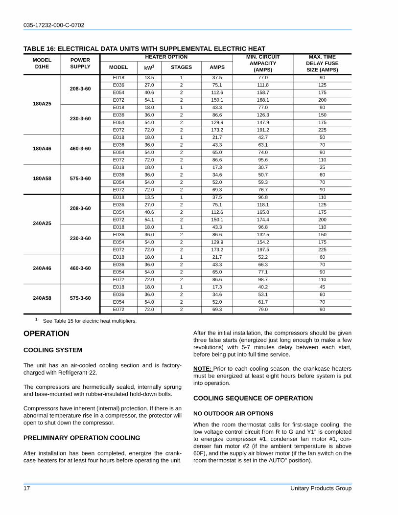
TABLE 16: ELECTRICAL DATA UNITS WITH SUPPLEMENTAL ELECTRIC HEAT
MODELD1HE
POWERSUPPLY
HEATER OPTION MIN. CIRCUITAMPACITY
(AMPS)
MAX. TIMEDELAY FUSESIZE (AMPS)MODEL kW1 STAGES AMPS
180A25
208-3-60
E018 13.5 1 37.5 77.0 90
E036 27.0 2 75.1 111.8 125
E054 40.6 2 112.6 158.7 175
E072 54.1 2 150.1 168.1 200
230-3-60
E018 18.0 1 43.3 77.0 90
E036 36.0 2 86.6 126.3 150
E054 54.0 2 129.9 147.9 175
E072 72.0 2 173.2 191.2 225
180A46 460-3-60
E018 18.0 1 21.7 42.7 50
E036 36.0 2 43.3 63.1 70
E054 54.0 2 65.0 74.0 90
E072 72.0 2 86.6 95.6 110
180A58 575-3-60
E018 18.0 1 17.3 30.7 35
E036 36.0 2 34.6 50.7 60
E054 54.0 2 52.0 59.3 70
E072 72.0 2 69.3 76.7 90
240A25
208-3-60
E018 13.5 1 37.5 96.8 110
E036 27.0 2 75.1 118.1 125
E054 40.6 2 112.6 165.0 175
E072 54.1 2 150.1 174.4 200
230-3-60
E018 18.0 1 43.3 96.8 110
E036 36.0 2 86.6 132.5 150
E054 54.0 2 129.9 154.2 175
E072 72.0 2 173.2 197.5 225
240A46 460-3-60
E018 18.0 1 21.7 52.2 60
E036 36.0 2 43.3 66.3 70
E054 54.0 2 65.0 77.1 90
E072 72.0 2 86.6 98.7 110
240A58 575-3-60
E018 18.0 1 17.3 40.2 45
E036 36.0 2 34.6 53.1 60
E054 54.0 2 52.0 61.7 70
E072 72.0 2 69.3 79.0 90
1 See Table 15 for electric heat multipliers.

035-17232-000-C-0702
Unitary Products Group 18
When the thermostat calls for second-stage cooling, the lowvoltage control circuit from R to Y2 is completed to energizecompressor #2.
After the thermostat is satisfied and opens, all componentswill stop simultaneously. The blower motor will continue tooperate if the fan switch on the room thermostat is set in theON position.
ECONOMIZER WITH SINGLE ENTHALPY SENSOR
When the room thermostat calls for first-stage cooling, thelow voltage control circuit from R to G and Y1 is completed.The R to G circuit energizes the blower motor (if the fanswitch on the room thermostat is set in the AUTO position)and drives the economizer dampers from fully closed to theirminimum position. If the enthalpy of the outdoor air is belowthe setpoint of the enthalpy controller (previously deter-mined), Y1 energizes the economizer. The dampers will mod-ulate to maintain a constant supply air temperature asmonitored by the discharge air sensor. If the outdoor airenthalpy is above the setpoint, Y1" energizes compressor #1,condenser fan motor #1, and condenser fan motor #2 (if theambient temperature is above 60°F).
When the thermostat calls for second-stage cooling, the lowvoltage control circuit from R to Y2 is completed. If theenthalpy of the outdoor air is below the setpoint of theenthalpy controller (i.e. first stage has energized the econo-mizer), Y2 will energize compressor #1. If the outdoor air isabove the setpoint, Y2 will energize compressor #2.
After the thermostat is satisfied and opens, all componentswill stop simultaneously. The blower motor will continue tooperate if the fan switch on the room thermostat is set in theON position.
ECONOMIZER WITH DUAL ENTHALPY SENSORS
The operation with the dual enthalpy sensors is identical tothe single sensor except that a second enthalpy sensor ismounted in the return air. This return air sensor allows theeconomizer to choose between outdoor air and return air,whichever has the lowest enthalpy value, to provide maxi-mum operating efficiency.
ECONOMIZER (SINGLE OR DUAL) WITH POWEREXHAUST
This system operates as specified above with one addition.The power exhaust motor is energized whenever the econo-mizer is chosen by the enthalpy sensor for first stage cooling,Y1. As always, the R to G connection provides minimumposition but does not provide power exhaust operation.
MOTORIZED OUTDOOR AIR DAMPERS
This system operation is the same as the units with no out-door air options with one exception. When the R to G circuit iscomplete, the motorized damper drives open to a position set
by the thumbwheel on the damper motor. When the R to Gcircuit is opened, the damper spring returns fully closed.
SAFETY CONTROLS
Each refrigerant system is equipped with the following safetycontrols:
1. A Suction Line Freezestat to protect against low evapo-rator temperatures due to a low air flow or a low returnair temperature. (Opens at 26°F + 5°F and resets at 38°F+ 5°F)
2. A High Pressure Cutout Switch to protect against exces-sive discharge pressures due to a blocked condensercoil or a condenser motor failure. (Opens at 380 psig +10 and resets at 300 psig +10)
3. A Low Pressure Switch/Loss Of Charge to protectagainst loss of refrigerant charge. (Opens at 7 psig + 3and resets at 22 psig + 5)
If either one of the above safety controls opens, that individ-ual refrigerant system will be locked out. The other refrigerantsystem will continue in operation unless it too is effected bythe same fault. The lock out of either system can be reset byopening the 24V circuit either at the room thermostat or at theunit disconnect.
HEATING SEQUENCE OF OPERATION
SEQUENCE OF OPERATION WITH ELECTRIC HEATWITH POWER TO UNIT AND THERMOSTAT IN THE HEAT-ING MODE
Single-stage heating: (applies only to 18 KW heater, all otherheaters MUST use a two-stage thermostat):
a. If the fan switch is in the ON position, the evaporatorblower motor contactor (3M) will be energizedthrough terminal G to provide continuous bloweroperation. If the fan switch is in the AUTO position,the blower will operate only when there is a call forheating by the thermostat.
NOTE: All 240 & 480V heaters are provided with manualreset backup protection limits. These will de-energize theheaters should the primary limit fail to open or the contactorsfail to open in a failure mode.
b. Upon a call for heat by the thermostat, the heatercontactor (6M) will be energized.
c. The thermostat will cycle the electric heat to satisfythe heating requirements of the conditioned space.
Two-stage heating: (applies to all heaters except 18 KW):
a. If the fan switch is in the ON position, the evaporatorblower motor contactor (3M) will be energizedthrough terminal G to provide continuous blower

035-17232-000-C-0702
19 Unitary Products Group
operation. If the fan switch is in the AUTO position,the blower will operate only when there is a call forheating by the thermostat.
b. Upon a call for first-stage heat by the thermostat, theheater contactor (6M) (6M & 7M on 72 KW, 240V)will be energized.
If the second stage of heat is required, heater con-tactor (7M) will be energized. Note that on the 54KW, 240V heater, heater contactors (7M & 8M) willbe energized and on the 72 KW, 240V heater,heater contactors (8M & 9M) will be energized.
c. The thermostat will cycle the electric heat to satisfythe heating requirements of the conditioned space.
HEAT ANTICIPATOR SETPOINTS
It is important that the anticipator setpoint be correct. Toohigh of a setting will result in longer heat cycles and a greatertemperature swing in the conditioned space. Reducing thevalue below the correct setpoint will give shorter ON cyclesand may result in the lowering of the temperature within theconditioned space. Refer to Table 17 for the required heatanticipator setting.
CHECKING SUPPLY AIR CFM
The RPM of the supply air blower will depend on the requiredCFM, the unit options/accessories and the static resistancesof both the supply and the return air duct systems. With thisinformation, the RPM for the supply air blower and the motorpulley adjustment (turns open) can be determined from theblower performance data in Tables 10 and 11.
High speed drive accessories (containing a smaller blowerpulley and a shorter belt) are available for applications requir-ing the supply air blower to produce higher CFM's and/orhigher static pressures. Use Model 1LD0416 for 15 ton unitsand Model 1LD0417 for 20 ton units. Refer to Table 12 forblower motor and drive data.
Note the following:
1. The supply air CFM must be within the limitations shownin Table 2.
2. Pulleys can be adjusted in half turn increments.
3. The tension on the belt should be adjusted as shown inFigure 10.
Start the supply air blower motor. Adjust the resistances inboth the supply and the return air duct systems to balancethe air distribution throughout the conditioned space. The jobspecifications may require that this balancing be done bysomeone other than the equipment installer.
To check the supply air CFM after the initial balancing hasbeen completed:
1. Remove the two 5/16" dot plugs from the blower motorand the filter access panels shown in Figure 7, 8 and 9.
2. Insert at least 8" of 1/4 inch tubing into each of theseholes for sufficient penetration into the air flow on bothsides of the indoor coil.
NOTE: The tubes must be inserted and held in a position per-pendicular to the air flow so that velocity pressure will notaffect the static pressure readings.
3. Using an inclined manometer, determine the pressuredrop across a dry indoor coil. Since the moisture on anindoor coil may vary greatly, measuring the pressuredrop across a wet coil under field conditions would beinaccurate. To assure a dry coil, the compressors wouldbe de-activated while the test is being run.
4. Knowing the pressure drop across a dry coil, the actualCFM through the unit and clean two-inch filters, can bedetermined from the curve in Figure 11.
After readings have been obtained, remove the tubes andreinstall the two 5/16" dot plugs that were removed in Step 1.
NOTE: De-energize the compressors before taking any testmeasurements to assure a dry indoor coil.
BELT DRIVE BLOWER
All units have belt drive single-speed blower motors. The vari-able pitch pulley on the blower motor can be adjusted toobtain the desired supply air CFM. Tighten belts enough toprevent slipping, but do not overtighten. Belt deflectionshould be between 1/4" and 1/2" per foot.
TABLE 17: HEAT ANTICIPATOR SETTING
HEATERkW
VOLTAGESETTING, AMPS
TH1 TH2
18
208/230-3-60
0.29 -
36 0.29 0.59
54 0.29 0.29
72 0.29 0.29
18
460-3-60
0.29 -
36 0.29 0.29
54 0.29 0.29
72 0.29 0.29
18
575-3-60
0.29 -
36 0.29 0.29
54 0.29 0.29
72 0.29 0.29

035-17232-000-C-0702
Unitary Products Group 20
SECURE OWNER’S APPROVAL
When the system is functioning properly, secure the owner’sapproval. Show him the location of all disconnect switchesand the thermostat. Teach him how to start and stop the unitand how to adjust temperature settings within the limitationsof the system.
MAINTENANCE
NORMAL MAINTENANCE
FILTERS
Inspect once a month. Replace disposable or clean perma-nent type as necessary. DO NOT replace permanent typewith disposable. The dimensional size of the replacement fil-ter must be the same as the replaced filter.
MOTORS
1. Outdoor fan motors are permanently lubricated andrequire no maintenance.
2. Indoor Blower Motor and Drive features ball bearingsthat do not require periodic lubrication. Periodic lubrica-tion of the motor and bearings can extend the life of com-ponents but is optional.
On an annual basis, check the motor for accumulationsof dust, etc. that may block the cooling slots in the motorshell. Check for loose, damaged or misaligned drivecomponents. Check that all mounting bolts are tight.Replace defective parts as required.
FIGURE 10 : BELT ADJUSTMENT
Failure to properly adjust the total system air quan-tity can result in extensive blower damage.
Prior to any of the following maintenance proce-dures, shut off all electric power to the unit to pre-vent personal injury.
SPAN LENGTH
DEFL FORCE
(A) (C)*
(B)
* Never Loosen
Procedure for adjusting belt tension:
3. Never loosen nuts (C) from each other.2. Adjust the tension by turning bolt (B).
4. Use a belt tension checker to apply a perpendicular force to one belt at themidpoint of the span as shown. The deflection force should be applieduntil a specific deflection distance of 4mm (5/32")is obtained. To determinethe deflection distance from normal position, use a straight edge fromsheave to sheave as a reference line. The recommended deflection forceis as follows:
Tension new belts at the max. deflection force recommended for the beltsection. Check the belt tension at least two times during the first 24 hours ofoperation. Any re tensioning should fall between the min. and max.deflection force values.
5. After adjusting, re tighten nuts (A).
Loosen nuts (A) (top and bottom).1.
FIGURE 11 : PRESSURE DROP ACROSS A DRYINDOOR COIL VS SUPPLY AIR CFM
Damage can occur if the bearings are over lubri-cated. Use grease sparingly.

035-17232-000-C-0702
21 Unitary Products Group
If desired, every three years remove both pipe plugs ateach end shell and clean out any hardened grease orforeign matter. Replace one plug on each end with aclean grease fitting. Using a low pressure grease gun,pump grease (Chevron SRI-2 or equivalent) into thebearing cavity until new grease shows at the open port.Do not over lubricate. Run the motor for ten minutes untilexcess grease is purged from the cavity. Replace theplugs.
On 20 ton only, units are supplied with blower shaft bear-ings that do not require maintenance but may be relubri-cated if desired. Every three years, using a low pressuregrease gun, pump grease into the bearing grease fittinguntil grease just begins to show at the seals. Do not overlubricate. Use any lithium base grease recommended forball bearing service.
OUTDOOR COIL
Dirt should not be allowed to accumulate on the outdoor coilsurface or other parts in the air circuit. Cleaning should be asoften as necessary to keep coil clean. Use a brush, vacuumcleaner attachment, or other suitable means. If water is usedto clean coil, be sure electric power to the unit is shut off priorto cleaning.
NOTE: Exercise care when cleaning the coil so that the coilfins are not damaged.
NOTE: Do not permit the hot outdoor air discharge to beobstructed by overhanging structures or shrubs.
Perform all maintenance operations on the blowermotor with electric power disconnected from theunit. Do not attempt to lubricate bearings with theunit in operation.

035-17232-000-C-0702
Unitary Products Group 22
NOTES

035-17232-000-C-0702
23 Unitary Products Group
NOTES

Subject to change without notice. Printed in U.S.A. 035-17232-000-C-0702Copyright © by Unitary Products 2002. All rights reserved. Supersedes: 035-17232-000 Rev B (0500)
Unitary 5005 NormanProducts York OKGroup Drive 73069
NOTES