Y-0045 Y-0047 ROBOT TRAINING SET ... - afzarazma.com · SCORBASE and Robocell 3D robot programming...
1
[email protected] / www.yildirimelektronik.com 22 Y-0045 ROBOT TRAINING SET It is a platform that has been developed to use in factory automation systems in terms of programming and using of the robots. Robot Training Set is intended to train the robot for the position, to move the robot with the circular and direct commands as well as to operate the robot in various speeds, to hold and leave the object and to instruct the system integration. Operation of the System; as soon as the work piece is perceived, the conveyor will be moved. While the work pieces have been moving on the conveyor, the decomposition of metal or plastic could be performed by various sensors.The application program loaded to the robot controller will be settled in the appropriate roofs in complying with their materials and types and the robotic arm will be stepped in. On one hand, the Robocell 3D robot software submitted by the system will prompt the imagination of the pupils and on the other hand, it could pave the way for the pupils to set a model in the graphic environment immediately, to teach them various positions as well as to develop the program and simulation. On the simulation screen, in accordance with the scenarios to be prepared, the robot could be monitored real-time. The main components of the robot training set are robotic arm, controller, 3D software, conveyor mechanism and storing unit. The Robot Training Set is structured on the anodized aluminum sigma profile table. Due to the channel structure of the profiles, the various applications could be added on the set. TECHNICAL SPECIFICATIONS • • • • • • • • • • • • • • • • • • • • • • • 220 V Power Supply • Dimensions Robotic Arm Robot Controller Teach pendant Software Conveyor Units Storing Unit 5 degree of freedom (axes) and parallel gripper Payload Capacity: 2,1 kg Speed: 700 mm/sn Repeatability: 0,18 mm Working area: 610 mm (by gripper ) Axis 1:Base rotation 310° Axis 2:Shoulder rotation +130° /-35 Axis 3:Elbow rotation +130° Axis 4:Wrist pitch +130° Axis 5:Wrist roll ±570° PC Communication: USB (Plug&Play) Digital input/output number: 8 input/8 output Analog input/output: 4 input/2 output Position Description: Absolute, Relative, Cartesian, Joints, Encoders, Emergency stop, short circuit and over temperature protection, possible communication and for PC failure, the security precautions are available. SCORBASE and Robocell 3D robot programming and operating software DC Engine Conveying Belt 2 pieces optic sensor Inductive Sensor Capacitive Sensor 3 Fold PVC roof System Structure Anodized aluminum sigma profile Channel aluminum table (120x70 cm) : 120x150x70 (WxHxD) ACCESSORIES • • • • 1 user's guide and experiment booklet and application CD 1 Robocell 3 D and Scorbase robot programming software CD 1 USB robot programming cable 6 work pieces INDUSTRIAL AUTOMATION TECHNOLOGY LABORATORY TRAINING SETS [email protected] / www.yildirimelektronik.com
Transcript of Y-0045 Y-0047 ROBOT TRAINING SET ... - afzarazma.com · SCORBASE and Robocell 3D robot programming...
[email protected] / www.yildirimelektronik.com22 23
Y-0045ROBOT TRAINING SET
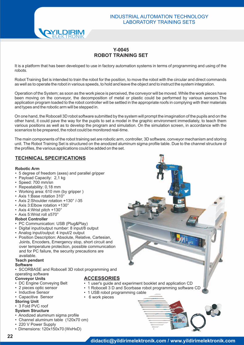
It is a platform that has been developed to use in factory automation systems in terms of programming and using of therobots.
Robot Training Set is intended to train the robot for the position, to move the robot with the circular and direct commandsas well as to operate the robot in various speeds, to hold and leave the object and to instruct the system integration.
Operation of the System; as soon as the work piece is perceived, the conveyor will be moved. While the work pieces havebeen moving on the conveyor, the decomposition of metal or plastic could be performed by various sensors.Theapplication program loaded to the robot controller will be settled in the appropriate roofs in complying with their materialsand types and the robotic arm will be stepped in.
On one hand, the Robocell 3D robot software submitted by the system will prompt the imagination of the pupils and on theother hand, it could pave the way for the pupils to set a model in the graphic environment immediately, to teach themvarious positions as well as to develop the program and simulation. On the simulation screen, in accordance with thescenarios to be prepared, the robot could be monitored real-time.
The main components of the robot training set are robotic arm, controller, 3D software, conveyor mechanism and storingunit. The Robot Training Set is structured on the anodized aluminum sigma profile table. Due to the channel structure ofthe profiles, the various applications could be added on the set.
TECHNICAL SPECIFICATIONS
••••••••••
••••
•
••••
•
••• 220 V Power Supply• Dimensions
Robotic Arm
Robot Controller
Teach pendantSoftware
Conveyor Units
Storing Unit
5 degree of freedom (axes) and parallel gripperPayload Capacity: 2,1 kgSpeed: 700 mm/snRepeatability: 0,18 mmWorking area: 610 mm (by gripper )Axis 1:Base rotation 310°Axis 2:Shoulder rotation +130° /-35Axis 3:Elbow rotation +130°Axis 4:Wrist pitch +130°Axis 5:Wrist roll ±570°
PC Communication: USB (Plug&Play)Digital input/output number: 8 input/8 outputAnalog input/output: 4 input/2 outputPosition Description: Absolute, Relative, Cartesian,Joints, Encoders, Emergency stop, short circuit andover temperature protection, possible communicationand for PC failure, the security precautions areavailable.
SCORBASE and Robocell 3D robot programming andoperating software
DC Engine Conveying Belt2 pieces optic sensorInductive SensorCapacitive Sensor
3 Fold PVC roofSystem Structure
Anodized aluminum sigma profileChannel aluminum table (120x70 cm)
: 120x150x70 (WxHxD)
ACCESSORIES••••
1 user's guide and experiment booklet and application CD1 Robocell 3 D and Scorbase robot programming software CD1 USB robot programming cable6 work pieces
Y-0047SERVOMOTOR TRAINING SET
TRAINING SUBJECTSArrangement and Monitoring of Servo Motor parameter valuesMonitoring of charge/discharge speed position and torc controlDiagnosis and defect repairComments and reviewing of the documentation
••••
ACCESSORIES•••• 2
1 user's guide and experiment booklet and application CDServo driver software CDServo driver-PC programming cable
0 pcs 2mm test cable
TECHNICAL SPECIFICATIONS•
••••
••••
Servo DriverWorking modes:
Speed Control and Torc Control :
Position Control:
PC Communication:Digital I/O:Main positioning:Encoder Dissolubility:
Servo Motor:PLC:Magnetic Dust Brake engine:Control Panel
Sensors:Power Supply:
Speed control, Torc control, Position Control(external and internal position), Position/Speed, Speed/Torc, Position/Torc
±10V analog input (0-4500 rpm) orDigital input (0-3000 rpm) could be assigned.Monitored or amended. max torc (3,82 Nm)
External Position (open collector or line driver pulse input)Internal Position (by digital inputs, the assigned 16 position)
RS232/RS485 Modbus, Windows based Setup software13 Programmable digital input, 8 programmable digital output
Home, origin search and position instruction functions.2500 ppr line driver (A/B/Z and others)
Internal braking unit , Notch filtered, protection functions and alarm messages, monitoring all I / O status, whileengine is running, the status information could be on-line monitored (Torc, rpm, pulse etc).
AC servo 400 W. 3000 rpm. Nom. 1,274 Nm.8 digital input/6 digital output
DC 24V, 6 Nm Handling Torc: 2 pieces 0..10 volt analog signal, Frequency adjustable pals generator, adjusted load control
circuit, all input/output signals could be monitored by led, encoder signal outputFor right and left limit, 2 optic sensors
24V.Emergency , start-stop buttons and contactorWith the timing belt 41 cm neck movement mechanism
Through the Servomotor application set, application of servomotor working with loaded-unloaded position, speed andtorc control as well as identification of parameter values could be performed.
In the control panel; load set potentiometer, 2 pieces 0..10V adjusted analogue output, servo input and outputs have beenconfigured manual or in the appropriate structure controlled by PLC as well as adjusted pals generator has beenconfigured by 2 mm sockets.
The load assembly was provided on the set by magnetic dust brake engine, coupled by the timing belt. Due to thisassembly, control of the speed-torc of the servo engine or control of the position torc could be reviewed. By means of PCconnection, all parameter information could be monitored, amended and recorded. The torc and speed of the enginecould be monitored in the interface and printed out.
In the position controls, the left and right limits could be perceived by the optic sensors. In order to monitor the angularmotions, the scaled disc is available on the engine.
The servomotor training set was set by anodized sigma aluminum profileand mounted on the channeled lab desk. In this way, add/drop and replacing process on the system could be done easily.The leg of the table could be locked and it is wheeled structure.
INDUSTRIAL AUTOMATION TECHNOLOGYLABORATORY TRAINING SETS
INDUSTRIAL AUTOMATION TECHNOLOGYLABORATORY TRAINING SETS
[email protected] / www.yildirimelektronik.com [email protected] / www.yildirimelektronik.com
s_noroozi
new eaa 2