XV-5080 ref
312
Notation Used in This Owner’s Manual To make operation procedures easy to understand, the following notation system is adopted: Characters and numbers in square brackets [ ] indicate buttons on the front panel. For example, [PATCH] represents the PATCH button and [ENTER] the ENTER button. An asterisk (*) at the beginning of a paragraph indicates a note or precaution. (p. **) refers to pages within the manual. * The display screens printed in this owner’s manual are based on the factory settings. However, please be aware that in some cases they may differ from the actual factory settings. OWNER’S MANUAL * Microsoft and MS-DOS are registered trademarks of Microsoft Corporation. * Microsoft, Windows, and Windows NT are registered trademarks of Microsoft Corporation. * Windows® 3.1 is known officially as: “Microsoft® Windows® operating system Version 3.1.” * Windows® 95 is known officially as: “Microsoft® Windows® 95 operating system.” * Windows® 98 is known officially as: “Microsoft® Windows® 98 operating system.” * MacOS is a trademark of Apple Computer, Inc. * Zip is a trademark of Iomega Corporation. * SmartMedia is a trademark of Toshiba Corporation. * All product names mentioned in this document are trademarks or registered trademarks of their respective owners. Copyright © 2000 ROLAND CORPORATION All rights reserved. No part of this publication may be reproduced in any form without the written permission of ROLAND CORPORATION. Before using this unit, carefully read the sections entitled: “IMPORTANT SAFETY INSTRUC- TIONS” (p. 2), “USING THE UNIT SAFELY” (p. 3), and “IMPORTANT NOTES” (p. 5). These sections provide important information concerning the proper operation of the unit. Addi- tionally, in order to feel assured that you have gained a good grasp of every feature provided by your new unit, Owner’s Manual and Quick Start should be read in its entirety. The manual should be saved and kept on hand as a convenient reference. Thank you, and congratulations on your choice of the Roland XV-5080.
description
xv instructions
Transcript of XV-5080 ref
Notation Used in This Owner’s Manual
To make operation procedures easy to understand, the following notation system is adopted:
Characters and numbers in square brackets [ ] indicate buttons on the front panel. For example, [PATCH] represents the PATCH button and [ENTER] the ENTER button.
An asterisk (*) at the beginning of a paragraph indicates a note or precaution.(p. **) refers to pages within the manual.
* The display screens printed in this owner’s manual are based on the factory settings.
However, please be aware that in some cases they may differ from the actual factory settings.
XV
-5080 OW
NE
R’S
MA
NU
AL
02019812 ’01-3-B3-51K
OWNER’S MANUAL
*
Microsoft and MS-DOS are registered trademarks of Microsoft Corporation.
*
Microsoft, Windows, and Windows NT are registered trademarks of Microsoft Corporation.
*
Windows® 3.1 is known officially as: “Microsoft® Windows® operating system Version 3.1.”
*
Windows® 95 is known officially as: “Microsoft® Windows® 95 operating system.”* Windows® 98 is known officially as: “Microsoft® Windows® 98 operating system.”* MacOS is a trademark of Apple Computer, Inc.* Zip is a trademark of Iomega Corporation.* SmartMedia is a trademark of Toshiba Corporation.* All product names mentioned in this document are trademarks or registered trademarks of their
respective owners.
Copyright © 2000 ROLAND CORPORATIONAll rights reserved. No part of this publication may be reproduced in any form without the
written permission of ROLAND CORPORATION.
Before using this unit, carefully read the sections entitled: “IMPORTANT SAFETY INSTRUC-
TIONS” (p. 2), “USING THE UNIT SAFELY” (p. 3), and “IMPORTANT NOTES” (p. 5). These
sections provide important information concerning the proper operation of the unit. Addi-
tionally, in order to feel assured that you have gained a good grasp of every feature provided
by your new unit, Owner’s Manual and Quick Start should be read in its entirety. The manual
should be saved and kept on hand as a convenient reference.
Thank you, and congratulations on your choice of the Roland XV-5080.
CAUTIONRISK OF ELECTRIC SHOCK
DO NOT OPEN
ATTENTION: RISQUE DE CHOC ELECTRIQUE NE PAS OUVRIR
CAUTION: TO REDUCE THE RISK OF ELECTRIC SHOCK,
DO NOT REMOVE COVER (OR BACK).
NO USER-SERVICEABLE PARTS INSIDE.
REFER SERVICING TO QUALIFIED SERVICE PERSONNEL.
The lightning flash with arrowhead symbol, within an equilateral triangle, is intended to alert the user to the presence of uninsulated “dangerous voltage” within the product’s enclosure that may be of sufficient magnitude to constitute a risk of electric shock to persons.
The exclamation point within an equilateral triangle is intended to alert the user to the presence of important operating and maintenance (servicing) instructions in the literature accompanying the product.
INSTRUCTIONS PERTAINING TO A RISK OF FIRE, ELECTRIC SHOCK, OR INJURY TO PERSONS.
IMPORTANT SAFETY INSTRUCTIONSSAVE THESE INSTRUCTIONS
WARNING - When using electric products, basic precautions should always be followed, including the following:
1. Read these instructions.2. Keep these instructions.3. Heed all warnings.4. Follow all instructions.5. Do not use this apparatus near water.6. Clean only with a dry cloth.7. Do not block any of the ventilation openings. Install in
accordance with the manufacturers instructions.8. Do not install near any heat sources such as radiators,
heat registers, stoves, or other apparatus (including amplifiers) that produce heat.
9. Do not defeat the safety purpose of the polarized or grounding-type plug. A polarized plug has two blades with one wider than the other. A grounding type plug has two blades and a third grounding prong. The wide blade or the third prong are provided for your safety. When the provided plug does not fit into your outlet, consult an electrician for replacement of the obsolete outlet.
WARNING:IMPORTANT:
As the colours of the wires in the mains lead of this apparatus may not correspond with the coloured markings identifying the terminals in your plug, proceed as follows:
The wire which is coloured GREEN-AND-YELLOW must be connected to the terminal in the plug which is marked by the letter E or by the safety earth symbol or coloured GREEN or GREEN-AND-YELLOW.
The wire which is coloured BLUE must be connected to the terminal which is marked with the letter N or coloured BLACK.The wire which is coloured BROWN must be connected to the terminal which is marked with the letter L or coloured RED.
THIS APPARATUS MUST BE EARTHEDTHE WIRES IN THIS MAINS LEAD ARE COLOURED IN ACCORDANCE WITH THE FOLLOWING CODE.GREEN-AND-YELLOW: EARTH, BLUE: NEUTRAL, BROWN: LIVE
For the U.K.
10. Protect the power cord from being walked on or pinched particularly at plugs, convenience receptacles, and the point where they exit from the apparatus.
11. Only use attachments/accessories specified by the manufacturer.
12. Never use with a cart, stand, tripod, bracket, or table except as specified by the manufacturer, or sold with the apparatus. When a cart is used, use caution when moving the cart/apparatus combination to avoid injury from tip-over.
13. Unplug this apparatus during lightning storms or when unused for long periods of time.
14. Refer all servicing to qualified service personnel. Servicing is required when the apparatus has been damaged in any way, such as power-supply cord or plug is damaged, liquid has been spilled or objects have fallen into the apparatus, the apparatus has been exposed to rain or moisture, does not operate normally, or has been dropped.
2
USING THE UNIT SAFELY
• Before using this unit, make sure to read the instructions below, and the Owner’s Manual.
..........................................................................................................• Do not open or perform any internal modifica-
tions on the unit. (The only exception would be where this manual provides specific instructions which should be followed in order to put in place user-installable options; see QuickStart (p. 3, p. 34), Reference Manual (p. 181).)
..........................................................................................................• Do not attempt to repair the unit, or replace parts
within it (except when this manual provides specific instructions directing you to do so). Refer all servicing to your retailer, the nearest Roland Service Center, or an authorized Roland distributor, as listed on the "Information" page.
..........................................................................................................• Never use or store the unit in places that are:
• Subject to temperature extremes (e.g., direct sunlight in an enclosed vehicle, near a heating duct, on top of heat-generating equipment); or are
• Damp (e.g., baths, washrooms, on wet floors); or are
• Humid; or are
• Exposed to rain; or are
• Dusty; or are
• Subject to high levels of vibration...........................................................................................................• This unit should be used only with a rack or stand
that is recommended by Roland.
..........................................................................................................
• When using the unit with a rack or stand recom-mended by Roland, the rack or stand must be carefully placed so it is level and sure to remain stable. If not using a rack or stand, you still need to make sure that any location you choose for placing the unit provides a level surface that will properly support the unit, and keep it from wobbling.
..........................................................................................................
• The unit should be connected to a power supply only of the type described in the operating instruc-tions, or as marked on the unit.
..........................................................................................................
• Do not excessively twist or bend the power cord, nor place heavy objects on it. Doing so can damage the cord, producing severed elements and short circuits. Damaged cords are fire and shock hazards!
..........................................................................................................• This unit, either alone or in combination with an
amplifier and headphones or speakers, may be capable of producing sound levels that could cause permanent hearing loss. Do not operate for a long period of time at a high volume level, or at a level that is uncomfortable. If you experience any hearing loss or ringing in the ears, you should immediately stop using the unit, and consult an audiologist.
..........................................................................................................• Do not allow any objects (e.g., flammable material,
coins, pins); or liquids of any kind (water, soft drinks, etc.) to penetrate the unit.
..........................................................................................................• In households with small children, an adult
should provide supervision until the child is capable of following all the rules essential for the safe operation of the unit.
..........................................................................................................• Protect the unit from strong impact. (Do not drop it!)
..........................................................................................................
Used for instructions intended to alert the user to the risk of injury or material damage should the unit be used improperly.
* Material damage refers to damage or other adverse effects caused with respect to the home and all its furnishings, as well to domestic animals or pets.
Used for instructions intended to alert the user to the risk of death or severe injury should the unit be used improperly.
The ● symbol alerts the user to things that must be carried out. The specific thing that must be done is indicated by the design contained within the circle. In the case of the symbol at left, it means that the power-cord plug must be unplugged from the outlet.
The symbol alerts the user to important instructions or warnings.The specific meaning of the symbol is determined by the design contained within the triangle. In the case of the symbol at left, it is used for general cautions, warnings, or alerts to danger.
The symbol alerts the user to items that must never be carried out (are forbidden). The specific thing that must not be done is indicated by the design contained within the circle. In the case of the symbol at left, it means that the unit must never be disassembled.
3
• Do not force the unit’s power-supply cord to share an outlet with an unreasonable number of other devices. Be especially careful when using extension cords—the total power used by all devices you have connected to the extension cord’s outlet must never exceed the power rating (watts/amperes) for the extension cord. Excessive loads can cause the insulation on the cord to heat up and eventually melt through.
..........................................................................................................• Before using the unit in a foreign country, consult
with your retailer, the nearest Roland Service Center, or an authorized Roland distributor, as listed on the "Information" page.
..........................................................................................................• Always turn the unit off and unplug the power
cord (QuickStart p. 8) before attempting instal-lation of the circuit board (SRX series, SR-JV80 series ; QuickStart p. 3).
• The unit should be located so that its location or position does not interfere with its proper venti-lation.
..........................................................................................................• Always grasp only the plug on the power-supply
cord when plugging into, or unplugging from, an outlet or this unit.
..........................................................................................................• Try to prevent cords and cables from becoming
entangled. Also, all cords and cables should be placed so they are out of the reach of children.
..........................................................................................................• Never climb on top of, nor place heavy objects on
the unit.
..........................................................................................................• Never handle the power cord or its plugs with wet
hands when plugging into, or unplugging from, an outlet or this unit.
..........................................................................................................• Before moving the unit, disconnect the power
plug from the outlet, and pull out all cords from external devices.
..........................................................................................................• Before cleaning the unit, turn off the power and
unplug the power cord from the outlet (QuickStart p. 12).
..........................................................................................................• Whenever you suspect the possibility of lightning
in your area, pull the plug on the power cord out of the outlet.
..........................................................................................................• Install only the specified circuit board(s) (SRX
series, SR-JV80 series). Remove only the specified screws (Quick Start p. 4).
..........................................................................................................• Should you remove the optical connector caps,
make sure to put them in a safe place out of children's reach, so there is no chance of them being swallowed accidentally.
..........................................................................................................
4

IMPORTANT NOTES
In addition to the items listed under “IMPORTANT SAFETY INSTRUCTIONS” and “USING THE UNIT SAFELY” on pages 2 and 3, please read and observe the following:
Power Supply• Do not use this unit on the same power circuit with any
device that will generate line noise (such as an electric motor or variable lighting system).
• Before connecting this unit to other devices, turn off the power to all units. This will help prevent malfunctions and/or damage to speakers or other devices.
Placement• This device may interfere with radio and television
reception. Do not use this device in the vicinity of such receivers.
• Do not expose the unit to direct sunlight, place it near devices that radiate heat, leave it inside an enclosed vehicle, or otherwise subject it to temperature extremes. Excessive heat can deform or discolor the unit.
• To avoid possible breakdown, do not use the unit in a wet area, such as an area exposed to rain or other moisture.
Maintenance• For everyday cleaning wipe the unit with a soft, dry cloth
or one that has been slightly dampened with water. To remove stubborn dirt, use a cloth impregnated with a mild, non-abrasive detergent. Afterwards, be sure to wipe the unit thoroughly with a soft, dry cloth.
• Never use benzine, thinners, alcohol or solvents of any kind, to avoid the possibility of discoloration and/or deformation.
Repairs and Data• Please be aware that all data contained in the unit’s
memory may be lost when the unit is sent for repairs. Important data should always be backed up Memory Card, or written down on paper (when possible). During repairs, due care is taken to avoid the loss of data. However, in certain cases (such as when circuitry related to memory itself is out of order), we regret that it may not be possible to restore the data, and Roland assumes no liability concerning such loss of data.
Memory Backup• This unit contains a battery which powers the unit’s
memory circuits while the main power is off. When this battery becomes weak, the message shown below will appear in the display. Once you see this message, have the battery replaced with a fresh one as soon as possible to avoid the loss of all data in memory. To have the battery replaced, consult with your retailer, the nearest Roland Service Center, or an authorized Roland distributor, as listed on the “Information” page.
“Battery Low”
Additional Precautions• Please be aware that the contents of memory can be
irretrievably lost as a result of a malfunction, or the improper operation of the unit. To protect yourself against the risk of loosing important data, we recommend that you periodically save a backup copy of important data you have stored in the unit’s memory, a memory card.
• Unfortunately, it may be impossible to restore the contents of data that was stored in the unit’s memory, a memory card, or another MIDI device (e.g., a sequencer) once it has been lost. Roland Corporation assumes no liability concerning such loss of data.
• Use a reasonable amount of care when using the unit’s buttons, sliders, or other controls; and when using its jacks and connectors. Rough handling can lead to malfunctions.
• Never strike or apply strong pressure to the display.• When connecting / disconnecting all cables, grasp the
connector itself—never pull on the cable. This way you will avoid causing shorts, or damage to the cable’s internal elements.
• A small amount of heat will radiate from the unit during normal operation.
• To avoid disturbing your neighbors, try to keep the unit’s volume at reasonable levels. You may prefer to use headphones, so you do not need to be concerned about those around you (especially when it is late at night).
• When you need to transport the unit, package it in the box (including padding) that it came in, if possible. Otherwise, you will need to use equivalent packaging materials.
• The display screens printed in this owner’s manual are based on the factory settings. However, please be aware that in some cases they may differ from the actual factory settings.
Before Using CardsUsing DATA Cards• Carefully insert the DATA card all the way in—until it is
firmly in place.
• Insert memory cards with the gold contacts facing downwards.
• Never touch the terminals of the DATA card. Also, avoid getting the terminals dirty.
5
Contents
USING THE UNIT SAFELY......................................................................3IMPORTANT NOTES ...............................................................................5
Features .................................................................................................11
Panel Descriptions................................................................................12Front Panel................................................................................................................................................. 12Rear Panel .................................................................................................................................................. 14
Chapter 1 Selecting and Playing a Sound ..........................................16Auditioning Sounds on the XV-5080 (Phrase Preview)...................................................................... 16
Setting the Way In Which Sounds Are Previewed................................................................... 16Playing a Patch on the XV-5080 from External MIDI Devices (MIDI Keyboard) ........................... 17
Setting the XV-5080’s MIDI Reception Channels ..................................................................... 17Selecting a Mode (Patch, Performance, or Rhythm Set) ..................................................................... 17Selecting Sound Libraries........................................................................................................................ 18Selecting a Patch ....................................................................................................................................... 19
Basic Procedure for Selecting a Patch......................................................................................... 19Selecting Patches by Category (Patch Finder) .......................................................................... 19Selecting Patches and Rhythm Sets from an External MIDI Device...................................... 21
Setting a Patch’s Pitch in Octave Steps (Octave Shift) ........................................................................ 23Selecting How a Patch Will Play (Polyphonic/Monophonic) ........................................................... 23
Chapter 2 Using the XV-5080 Effects ..................................................24Turning Effects On/Off ........................................................................................................................... 24Patch Mode Settings................................................................................................................................. 24
Routing Tones to Effects .............................................................................................................. 25Making Multi-Effects Settings..................................................................................................... 26Making Chorus Settings............................................................................................................... 26Making Reverb Settings ............................................................................................................... 28
Performance Mode Settings .................................................................................................................... 30Routing Part Outputs ................................................................................................................... 31Making Multi-Effects Settings..................................................................................................... 31Making Chorus Settings............................................................................................................... 32Making Reverb Settings ............................................................................................................... 34
Rhythm Set Mode Settings...................................................................................................................... 36Routing Tones to Effects .............................................................................................................. 37Making Multi-Effects Settings..................................................................................................... 37Making Chorus Settings............................................................................................................... 38Making Reverb Settings ............................................................................................................... 39
Settings in General MIDI Mode.............................................................................................................. 41Parameters for Each Multi-Effects ......................................................................................................... 41Copying Effect Settings ......................................................................................................................... 106
Chapter 3 Selecting Output Jacks.....................................................107Patch Mode Settings............................................................................................................................... 107
Signal (TONE) Flow.................................................................................................................... 107Parameters.................................................................................................................................... 108Example of Settings..................................................................................................................... 110
Performance Mode Settings .................................................................................................................. 111Signal (PART) Flow .................................................................................................................... 111Parameters.................................................................................................................................... 111Example of Settings..................................................................................................................... 113
Rhythm Set Mode Settings.................................................................................................................... 114Signal (RHYTHM TONE) Flow ................................................................................................ 114Parameters.................................................................................................................................... 114
Settings in General MIDI Mode............................................................................................................ 117
6
Signal (PART) Flow .................................................................................................................... 117Parameters.................................................................................................................................... 117
Digital Connections Using R-BUS........................................................................................................ 119Settings for the Digital Interface ([SYSTEM/UTILITY] - [F2 (Output)]) ............................ 119Eight-Channel R-BUS Digital Connection............................................................................... 120
Converting to the Various Digital Formats ........................................................................................ 121Digital Output to an ADAT....................................................................................................... 121Digital Output to a TASCAM DA Series ................................................................................. 122Digital Output to an AES/EBU Device.................................................................................... 123
Synchronizing the XV-5080 to the Word Clock arriving at WORD CLOCK IN ........................... 124
Chapter 4 Creating Patches ...............................................................125Types of Patches and Their Composition ........................................................................................... 125
Four-Tone Patch .......................................................................................................................... 125How a Tone Is Organized .......................................................................................................... 125Multi-partial Patch ...................................................................................................................... 126How a Partial Is Organized ....................................................................................................... 126
Selecting the Tones That Will Sound (Tone On/Off)........................................................................ 126Settings Common to the Entire Patch.................................................................................................. 127
Common (Patch Common) ........................................................................................................ 127Control (Patch Control) .............................................................................................................. 129Structure (Patch Structure) ........................................................................................................ 131K. Range (Patch Key Range) ...................................................................................................... 132V. Range (Patch Velocity Range) .............................................................................................. 133
Creating Four-Tone Patches.................................................................................................................. 134Tips for Creating a Patch............................................................................................................ 134More Advanced Editing of Tones............................................................................................. 134Tips for Selecting a Waveform .................................................................................................. 135Modifying the Waveform and Pitch ([F2] (WG)) ................................................................... 136Using the Filter to Modify the Brightness ([F3 (TVF)]).......................................................... 140Changing the Volume and Stereo Location ([F4 (TVA)])...................................................... 143Applying Vibrato or Tremolo ([F5 (LFO&CTL)])................................................................... 145
Creating Multi-Partial Patches ............................................................................................................. 148Assigning Partials ....................................................................................................................... 148Editing Partials ............................................................................................................................ 149Editing Samples........................................................................................................................... 150Using the Filter to Modify the Brightness ([F3 (TVF)]).......................................................... 152Making the Volume Change ([F4 (TVA)]) ............................................................................... 155Applying Vibrato or Tremolo ([F5 (LFO&CTL)])................................................................... 156
Making Effect Settings ........................................................................................................................... 158Saving Patches You Create.................................................................................................................... 158Copying the Settings of Another Patch (Patch Tone Copy) ............................................................. 158
Chapter 5 Creating a Performance....................................................159How a Performance Is Organized........................................................................................................ 159Basic Ways to Use Performances ......................................................................................................... 159Choosing the Parts to Play .................................................................................................................... 159Establishing Settings for an Entire Performance (COMMON)........................................................ 160Settings for Each Part ............................................................................................................................. 160
Comparing the Settings of Each Part as You Make Settings................................................. 161Setting the Keyboard Range ...................................................................................................... 161Selecting the Patch, and Setting the Volume, Pan, Pitch, and Polyphony.......................... 162Editing the Attack and Release of the Sound and Changing the Way the Sound is Played..163Establishing a Part’s MIDI Settings .......................................................................................... 164Confirming MIDI Information for Each MIDI Channel ........................................................ 166
Making Effect Settings ........................................................................................................................... 166Saving Performances You Create......................................................................................................... 166Copying the Settings of Another Part (Performance Part Copy) .................................................... 166
7
Editing a Patch or Rhythm Set in the Performance Mode................................................................ 167Palette Function........................................................................................................................... 167
Chapter 6 Creating Rhythm Sets.......................................................168How Percussion Instruments Are Organized .................................................................................... 168Using a MIDI Keyboard to Select a Percussion Instrument for Editing......................................... 168Settings Common to an Entire Rhythm Set ........................................................................................ 169Setting up Individual Rhythm Tones .................................................................................................. 170
Tips for Selecting a Waveform .................................................................................................. 170Modifying the Waveform, Pan and Pitch ([F2 (Key WG)])................................................... 171Tune............................................................................................................................................... 172FXM............................................................................................................................................... 172Using the Filter to Modify the Brightness ([F3 (Key TVF)]).................................................. 175Making the Volume Change ([F4 (Key TVA)]) ....................................................................... 177Other Settings ([F5 (Key Ctl)])................................................................................................... 179
Making Effect Settings ........................................................................................................................... 179Saving the Rhythm Set You Create...................................................................................................... 179Copying Settings from Some Other Rhythm Tone............................................................................ 180
Chapter 7 Loading a Variety of Data .................................................181Loading Sampler Libraries (CD-ROM) ............................................................................................... 181
Installing the SIMM (Memory Module)................................................................................... 181Cautions When Installing SIMM .............................................................................................. 181Removing SIMMs........................................................................................................................ 182Installation de la carte d'extension Wave (French language for Canadian Safety Standard) .. 183Connecting a CD-ROM Drive ................................................................................................... 185With Sampler Libraries .............................................................................................................. 185About Each Sampler Library Folder Type (Display) ............................................................. 187About the Display of Folder Categories in Sampler Libraries ............................................. 188Sample Load ................................................................................................................................ 188Auto Load..................................................................................................................................... 189
Playing Back Loaded Sampler Libraries ............................................................................................. 190Loading Data Saved on a Zip Disk ...................................................................................................... 190
Individually Loading Patches, Performances, or Rhythm Sets............................................ 190Loading Data Stored on Memory Cards ............................................................................................. 191Sample-Related Utilities ........................................................................................................................ 191
Sending and Receiving Samples (Sample Dump).................................................................. 191Emphasizing and Suppressing the High End of Loaded Samples (Emphasis) ................. 192Automatically Creating Multi-Partial Patches (Create Patch).............................................. 193
Chapter 8 Saving Tones and Other Data You’ve Created ...............194Saving Edits to the XV-5080’s Internal Memory (Write) .................................................................. 194
When Changing the Settings for the Patch or Rhythm Set Assigned to a Part in a Performance .............................................................................................................. 195
Saving All Data to Memory Card ([DISK] - [F2 (SAVE)]) ................................................................ 195Formatting a Memory Card....................................................................................................... 196Saving Data .................................................................................................................................. 196Organizing the Contents of Memory Cards............................................................................ 197
Saving All Data to Zip Disk ([DISK] - [F2 (SAVE)]) .......................................................................... 200Formatting a Zip Disk/Hard Disk (Format) ........................................................................... 200Saving Data .................................................................................................................................. 200Organizing a Zip Disk ................................................................................................................ 201
Initializing a Sound ................................................................................................................................ 202For Patches or Performances ..................................................................................................... 202For Rhythm Sets .......................................................................................................................... 202Changing the Way MIDI Signals Arriving at MIDI IN 2 Are Handled .............................. 203
Transmitting Data to an External MIDI Device (Data Transfer) ..................................................... 203Transmitting to an External MIDI Device ............................................................................... 203Destination ................................................................................................................................... 204
8
Transmitting to User Memory................................................................................................... 204Protecting the Internal Memory (Protect) ........................................................................................... 205Resetting All Settings to Default Factory Settings (Factory) ............................................................ 206Registering Favorite Patches in the FAVORITE LIST ....................................................................... 207Selecting Patches from the FAVORITE LIST...................................................................................... 207
Chapter 9 Other Settings/Status Checks..........................................208Settings Common to the Entire XV-5080 ([SYSTEM/UTILITY] - [F1 (General)])......................... 208
Making Overall Settings............................................................................................................. 208Setting the Tuning and Volume Settings ................................................................................. 209Setting the System Tempo ......................................................................................................... 209
Making Scale Tune Settings ([SYSTEM/UTILITY] - [F1 (General)]) .............................................. 209Making the Equalizer Settings ([SYSTEM/UTILITY] - [F2 (Outp&EQ)] - [F2 (EQ)]) .................. 211Establishing the MIDI Settings ([SYSTEM/UTILITY] - [F3 (MIDI)]).............................................. 211
Setting the MIDI Channel .......................................................................................................... 212Setting the MIDI Transmit/Receive Switch ............................................................................ 212Making the System Exclusive Settings..................................................................................... 212Specifying the Reception Status for Each Tone ...................................................................... 212MIDI IN connectors .................................................................................................................... 213Connecting Two or More XV-5080s to Increase Polyphony................................................. 214
Selecting Common Controllers ([SYSTEM/UTILITY] - [F4 (Control)]) ......................................... 215Confirming the Current Status ([SYSTEM/UTILITY] - [F6 (Info)])................................................ 215
Chapter 10 Examples of Applications Using the XV-5080 ..............217Controlling the XV-5080 in Real Time Using an External MIDI Device ........................................ 217
Changing the Multi-Effects Settings From an External MIDI Device ................................. 217Modifying Tone Settings............................................................................................................ 218
Applications for Patches........................................................................................................................ 219Syncing the LFO Cycle to System Tempo ............................................................................... 219Modifying Multi-Effects to Match the System’s Tempo........................................................ 219Making a Tone’s Delay Time Match the System Tempo....................................................... 220Using a Pedal Switch to Modify the Rotary Speed of the Rotary Effect ............................. 220Playing Phrase Loops at a System’s Tempo............................................................................ 220
Changing the Part Settings from an External MIDI Device ............................................................. 221Applications for Matrix Control........................................................................................................... 223
Controlling the TMT with the LFO and Changing the Tone’s Cycle Time Plays.............. 223Using the XV-5080 as a General MIDI Sound Module ..................................................................... 224
Entering GM Mode ..................................................................................................................... 224Turning Effects On/Off.............................................................................................................. 225Modifying GM Mode Settings................................................................................................... 225Utility Functions in GM Mode .................................................................................................. 228
Protecting the Internal Memory (PROTECT) ..................................................................................... 229
Troubleshooting..................................................................................232No sound ................................................................................................................................................. 232Can’t select Performances ..................................................................................................................... 232Can’t select the Part for which to make settings ................................................................................ 232Pitch is wrong ......................................................................................................................................... 232Effects do not apply................................................................................................................................ 233MIDI messages are not received correctly .......................................................................................... 233Memory Card cannot be used .............................................................................................................. 233Song data does not playback correctly................................................................................................ 233The SCSI device is not being recognized. ........................................................................................... 233
Error Messages ...................................................................................235
About SCSI ..........................................................................................239Connecting a SCSI device...................................................................................................................... 239
9
10
SCSI DWhat you nee
Types oAbout About About Making
Parameter Lis
Patch PPerformRhythmGM MoMFX PSystem
Waveform Lis
MIDI Impleme
Specification
evices That Can Be Used................................................................................................ 239d to know before making connections........................................................................ 239f SCSI cables and SCSI connectors .............................................................................. 239
SCSI Chains...................................................................................................................... 239Terminators...................................................................................................................... 239SCSI ID Numbers............................................................................................................ 240 Connections................................................................................................................... 240
t .....................................................................................241arameters......................................................................................................................... 241ance Parameters ............................................................................................................ 249 Set Parameters .............................................................................................................. 252de Parameters................................................................................................................. 255
rameters ............................................................................................................................ 257 Parameters ...................................................................................................................... 276
t .....................................................................................277
ntation...........................................................................282
s......................................................................................306
Features
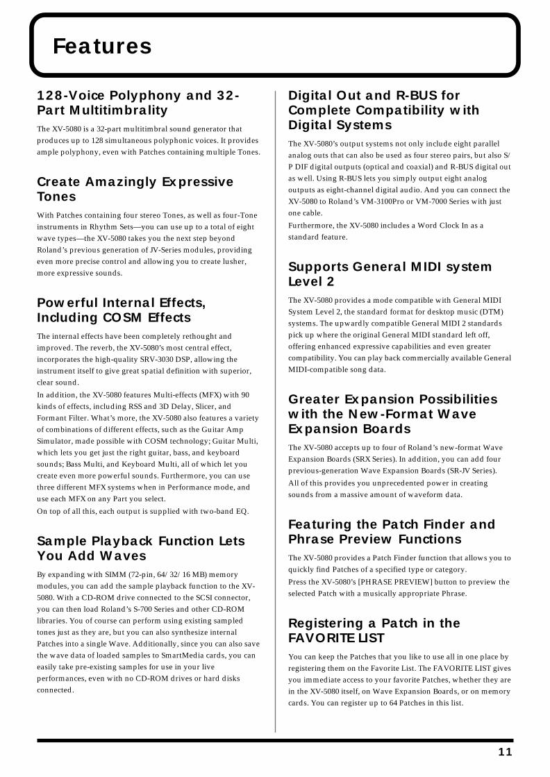
128-Voice Polyphony and 32-Part MultitimbralityThe XV-5080 is a 32-part multitimbral sound generator that produces up to 128 simultaneous polyphonic voices. It provides ample polyphony, even with Patches containing multiple Tones.
Create Amazingly Expressive TonesWith Patches containing four stereo Tones, as well as four-Tone instruments in Rhythm Sets—you can use up to a total of eight wave types—the XV-5080 takes you the next step beyond Roland’s previous generation of JV-Series modules, providing even more precise control and allowing you to create lusher, more expressive sounds.
Powerful Internal Effects, Including COSM EffectsThe internal effects have been completely rethought and improved. The reverb, the XV-5080’s most central effect, incorporates the high-quality SRV-3030 DSP, allowing the instrument itself to give great spatial definition with superior, clear sound.
In addition, the XV-5080 features Multi-effects (MFX) with 90 kinds of effects, including RSS and 3D Delay, Slicer, and Formant Filter. What’s more, the XV-5080 also features a variety of combinations of different effects, such as the Guitar Amp Simulator, made possible with COSM technology; Guitar Multi, which lets you get just the right guitar, bass, and keyboard sounds; Bass Multi, and Keyboard Multi, all of which let you create even more powerful sounds. Furthermore, you can use three different MFX systems when in Performance mode, and use each MFX on any Part you select.
On top of all this, each output is supplied with two-band EQ.
Sample Playback Function Lets You Add WavesBy expanding with SIMM (72-pin, 64/32/16 MB) memory modules, you can add the sample playback function to the XV-5080. With a CD-ROM drive connected to the SCSI connector, you can then load Roland’s S-700 Series and other CD-ROM libraries. You of course can perform using existing sampled tones just as they are, but you can also synthesize internal Patches into a single Wave. Additionally, since you can also save the wave data of loaded samples to SmartMedia cards, you can easily take pre-existing samples for use in your live performances, even with no CD-ROM drives or hard disks connected.
Digital Out and R-BUS for Complete Compatibility with Digital SystemsThe XV-5080’s output systems not only include eight parallel analog outs that can also be used as four stereo pairs, but also S/P DIF digital outputs (optical and coaxial) and R-BUS digital out as well. Using R-BUS lets you simply output eight analog outputs as eight-channel digital audio. And you can connect the XV-5080 to Roland’s VM-3100Pro or VM-7000 Series with just one cable.
Furthermore, the XV-5080 includes a Word Clock In as a standard feature.
Supports General MIDI system Level 2The XV-5080 provides a mode compatible with General MIDI System Level 2, the standard format for desktop music (DTM) systems. The upwardly compatible General MIDI 2 standards pick up where the original General MIDI standard left off, offering enhanced expressive capabilities and even greater compatibility. You can play back commercially available General MIDI-compatible song data.
Greater Expansion Possibilities with the New-Format Wave Expansion BoardsThe XV-5080 accepts up to four of Roland’s new-format Wave Expansion Boards (SRX Series). In addition, you can add four previous-generation Wave Expansion Boards (SR-JV Series).
All of this provides you unprecedented power in creating sounds from a massive amount of waveform data.
Featuring the Patch Finder and Phrase Preview FunctionsThe XV-5080 provides a Patch Finder function that allows you to quickly find Patches of a specified type or category.
Press the XV-5080’s [PHRASE PREVIEW] button to preview the selected Patch with a musically appropriate Phrase.
Registering a Patch in the FAVORITE LISTYou can keep the Patches that you like to use all in one place by registering them on the Favorite List. The FAVORITE LIST gives you immediate access to your favorite Patches, whether they are in the XV-5080 itself, on Wave Expansion Boards, or on memory cards. You can register up to 64 Patches in this list.
11
1
Panel Descriptions
Front Panelfig.0-001
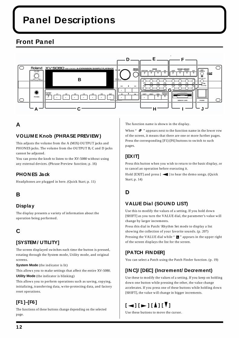
A
VOLUME Knob (PHRASE PREVIEW)This adjusts the volume from the A (MIX) OUTPUT jacks and PHONES jacks. The volume from the OUTPUT B, C and D jacks cannot be adjusted.
You can press the knob to listen to the XV-5080 without using any external devices. (Phrase Preview function; p. 16)
PHONES JackHeadphones are plugged in here. (Quick Start; p. 11)
B
DisplayThe display presents a variety of information about the operation being performed.
C
[SYSTEM/UTILITY]The screen displayed switches each time the button is pressed, rotating through the System mode, Utility mode, and original screens.
System Mode (the indicator is lit)
This allows you to make settings that affect the entire XV-5080.
Utility Mode (the indicator is blinking)
This allows you to perform operations such as saving, copying, initializing, transferring data, write-protecting data, and factory reset operations.
[F1]–[F6]The functions of these buttons change depending on the selected page.
The function name is shown in the display.
When “ ” appears next to the function name in the lower row of the screen, it means that there are one or more further pages. Press the corresponding [F1]-[F6] buttons to switch to such pages.
[EXIT]Press this button when you wish to return to the basic display, or to cancel an operation before executing it.
Hold [EXIT] and press [ ] to hear the demo songs. (Quick Start; p. 14)
D
VALUE Dial (SOUND LIST)Use this to modify the values of a setting. If you hold down [SHIFT] as you turn the VALUE dial, the parameter’s value will change by larger increments.
Press this dial in Patch/Rhythm Set mode to display a list showing the collection of your favorite sounds. (p. 207)
Pressing the VALUE dial while “ ” appears in the upper right of the screen displays the list for the screen.
[PATCH FINDER]You can select a Patch using the Patch Finder function. (p. 19)
[INC]/[DEC] (Increment/Decrement)Use these to modify the values of a setting. If you keep on holding down one button while pressing the other, the value change accelerates. If you press one of these buttons while holding down [SHIFT], the value will change in bigger increments.
[ ] [ ] [ ] [ ]Use these buttons to move the cursor.
AA C
D E F
J
G
B
H I
2

Panel Descriptions
E (MODE)
[PERFORM] (Performance)Pressed to get into Performance mode. (p. 17)
Press this button while holding down [SHIFT] to switch to Part Play mode, enabling you to make changes to the settings for the Patch and Rhythm Set assigned to each Part. (p. 167)
[PATCH]Pressed to get into Patch mode. (p. 17)
[RHYTHM] (Rhythm Set)Selects Rhythm Set mode. (p. 17)
[GM]Press this to enter General MIDI mode. (p. 17)
F (SOUND LIBRARY)
[USER]Selects a sound from the USER library. (p. 18)
[CARD]Selects a sound from an installed memory card, sold separately. (p. 18)
[PRESET]Selects a sound from the PRESET library. (p. 18)
[EXP]Selects a sound from a Wave Expansion Board (sold separately). (p. 18, Quick Start; p. 22)
G
PART SELECT [1/17]–[16/32]Selects a Part whose settings you wish to change. (p. 160)
Switches each Part on or off. (p. 159)
TONE SWITCH [1]–[4]Switches each Tone on or off. (p. 126)
TONE SELECT [1]–[4]Selects a Tone whose settings you wish to change. (p. 134)
[A]–[H]Selects a sound from the Sound Library.
H
[SHIFT]This is used in combination with other buttons. Holding down this button changes the functions of other buttons.
[UNDO]Use this to restore a modified parameter value to its original setting.
[DISK]Selects Disk mode.
[EFFECTS ON/OFF]Use this to turn the internal effects (Multi-effects, Chorus, Reverb) on or off. (p. 24)
I
MEMORY CARD SlotA memory card (SmartMedia) can be inserted here. (p. 195)
J
[MIDI MESSAGE/RX] (MIDI Message Indicator/Receive Switch)MIDI MESSAGE: This will light when a MIDI message is received.
RX: This turns Parts on and off in Performance mode and GM mode. (p. 159)
[1-16/17-32]This specifies whether the PART SELECT [1/17]–[16/32] buttons will select Parts 1–16 or Parts 17–32.
When this button is lit, Parts 17–32 can be selected.
POWER SwitchTurns the XV-5080’s power on and off. (Quick Start; p. 12)
13
Panel Descriptions
Rear Panelfig.0-002
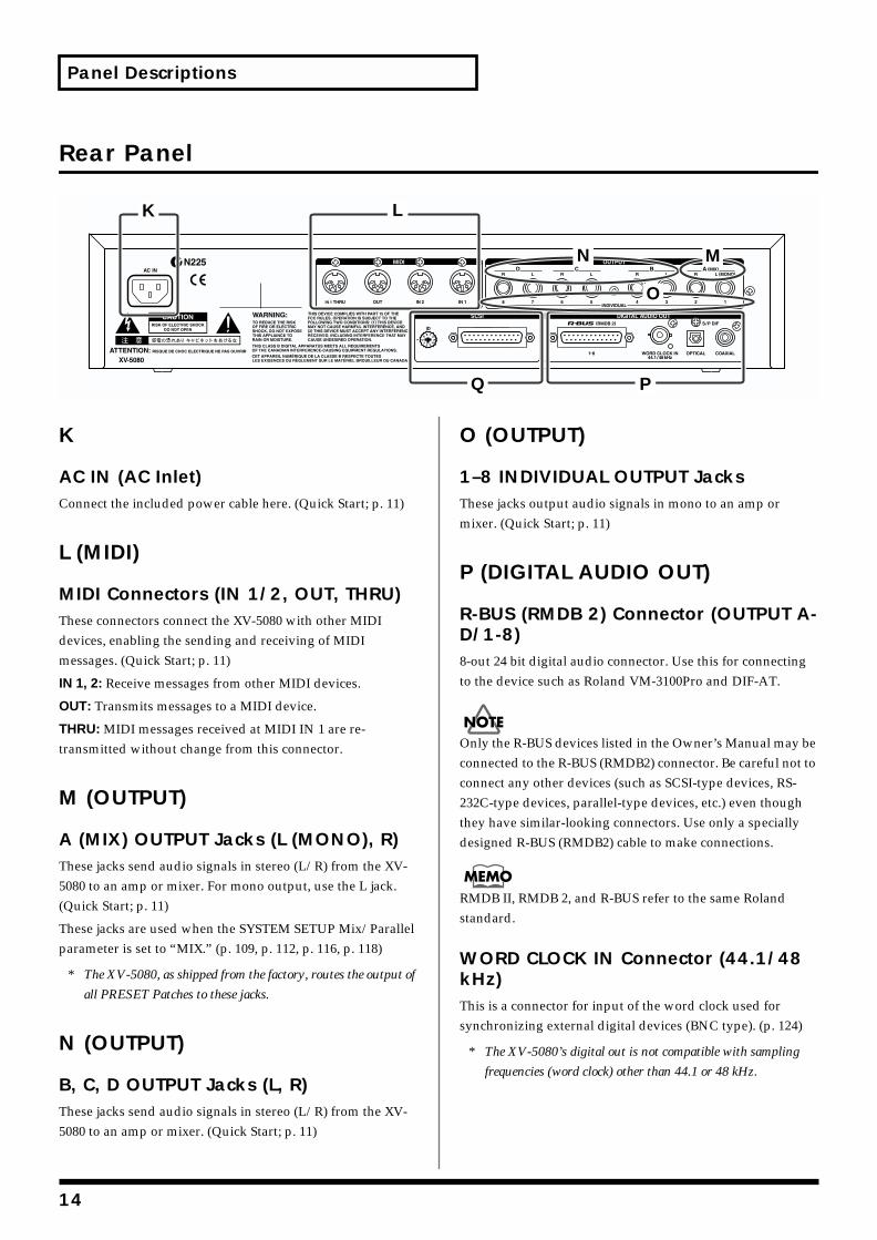
K
AC IN (AC Inlet)Connect the included power cable here. (Quick Start; p. 11)
L (MIDI)
MIDI Connectors (IN 1/2, OUT, THRU)These connectors connect the XV-5080 with other MIDI devices, enabling the sending and receiving of MIDI messages. (Quick Start; p. 11)
IN 1, 2: Receive messages from other MIDI devices.
OUT: Transmits messages to a MIDI device.
THRU: MIDI messages received at MIDI IN 1 are re-transmitted without change from this connector.
M (OUTPUT)
A (MIX) OUTPUT Jacks (L (MONO), R)These jacks send audio signals in stereo (L/R) from the XV-5080 to an amp or mixer. For mono output, use the L jack. (Quick Start; p. 11)
These jacks are used when the SYSTEM SETUP Mix/Parallel parameter is set to “MIX.” (p. 109, p. 112, p. 116, p. 118)
* The XV-5080, as shipped from the factory, routes the output of
all PRESET Patches to these jacks.
N (OUTPUT)
B, C, D OUTPUT Jacks (L, R)These jacks send audio signals in stereo (L/R) from the XV-5080 to an amp or mixer. (Quick Start; p. 11)
O (OUTPUT)
1–8 INDIVIDUAL OUTPUT JacksThese jacks output audio signals in mono to an amp or mixer. (Quick Start; p. 11)
P (DIGITAL AUDIO OUT)
R-BUS (RMDB 2) Connector (OUTPUT A-D/1-8)8-out 24 bit digital audio connector. Use this for connecting to the device such as Roland VM-3100Pro and DIF-AT.
Only the R-BUS devices listed in the Owner’s Manual may be connected to the R-BUS (RMDB2) connector. Be careful not to connect any other devices (such as SCSI-type devices, RS-232C-type devices, parallel-type devices, etc.) even though they have similar-looking connectors. Use only a specially designed R-BUS (RMDB2) cable to make connections.
RMDB II, RMDB 2, and R-BUS refer to the same Roland standard.
WORD CLOCK IN Connector (44.1/48 kHz)This is a connector for input of the word clock used for synchronizing external digital devices (BNC type). (p. 124)
* The XV-5080’s digital out is not compatible with sampling
frequencies (word clock) other than 44.1 or 48 kHz.
K L
PQ
N M
O
14
Panel Descriptions
S/P DIF OUT ConnectorThe XV-5080 features both optical and coaxial digital out connectors (conforming to S/P DIF).
S/P DIF: This is a digital interface format used for consumer digital audio devices.
* About the Optical Connector Protecting Cap
• If you remove the protecting cap, be sure to keep in a safe place to prevent loss.
• Always place the protecting cap on the optical connector when the connector is not in use.
• If you use the optical connector, be sure that the connector cover you removed is placed out of the reach of children.
Q
SCSI ConnectorThis is a DB-25 type SCSI connector for connecting SCSI devices such as a CD-ROM drive, a Zip disk drive or a hard disk drive.
Rotate the ID switch to set the SCSI ID numbers so that none of the devices have the same ID number. (p. 239)
* On the XV-5080, “8” and “9” of the ID switch are not used.
15
1
Chapter 1 Selecting and Playing a Sound
Auditioning Sounds on the XV-5080 (Phrase Preview)The Phrase Preview feature allows you to audition Patches on the XV-5080 even when it’s not connected to a MIDI keyboard or sequencer. You can preview a Patch using a Phrase that’s appropriate to the Patch’s type or category.
1. Press [PATCH], getting its indicator to light.
2. Turn the VALUE dial, or press [INC]/[DEC] to select the desired Patch.
3. Press and hold the VOLUME knob.
The phrase prepared for the Patch will play while the knob is pushed.
* When you preview a Rhythm Set, the XV-5080 plays a
percussion Phrase. Phrase Preview also allows you to audition
a Performance — when you preview a Performance, you hear a
Phrase appropriate to the currently selected Part.
* A USER Patch or a Patch from an optional Wave Expansion
Board (SRX/SR-JV80 series) may not preview in its normal
pitch range. If this occurs, press [ ] or [ ] (Octave Shift
function; p. 23) to select the desired pitch range.
* If the pitch range of a Phrase is wider than the range of the
Tones within a Patch (p. 132), or wider than the range of a
Part within a Performance (p. 161), any notes in the Phrase
that fall outside that range will not be heard.
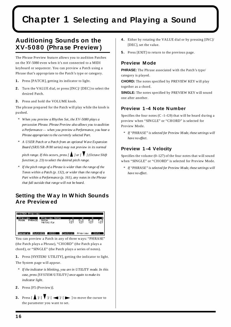
Setting the Way In Which Sounds Are Previewedfig.01-000.e_70
You can preview a Patch in any of three ways: “PHRASE” (the Patch plays a Phrase), “CHORD” (the Patch plays a chord), or “SINGLE” (the Patch plays a series of notes).
1. Press [SYSTEM/UTILITY], getting the indicator to light.
The System page will appear.
* If the indicator is blinking, you are in UTILITY mode. In this
case, press [SYSTEM/UTILITY] once again to make its
indicator light.
2. Press [F5 (Preview)].
3. Press [ ]/[ ]/[ ]/[ ] to move the cursor to the parameter you want to set.
4. Either by rotating the VALUE dial or by pressing [INC]/[DEC], set the value.
5. Press [EXIT] to return to the previous page.
Preview ModePHRASE: The Phrase associated with the Patch’s type/category is played.
CHORD: The notes specified by PREVIEW KEY will play together as a chord.
SINGLE: The notes specified by PREVIEW KEY will sound one after another.
Preview 1–4 Note NumberSpecifies the four notes (C -1–G9) that will be heard during a preview when “SINGLE” or “CHORD” is selected for Preview Mode.
* If “PHRASE” is selected for Preview Mode, these settings will
have no effect.
Preview 1–4 VelocitySpecifies the volume (0–127) of the four notes that will sound when “SINGLE” or “CHORD” is selected for Preview Mode.
* If “PHRASE” is selected for Preview Mode, these settings will
have no effect.
6
Chapter 1 Selecting and Playing a Sound
Chap.1
Playing a Patch on the XV-5080 from External MIDI Devices (MIDI Keyboard)The XV-5080 produces sound in response to MIDI messages that it receives from an external MIDI device such as a MIDI keyboard or sequencer. In order for this to occur, the MIDI transmission channels of the external device must match the MIDI reception channels of the XV-5080.
For details on setting the MIDI transmission channels of your external MIDI device, refer to its owner’s manual.
Setting the XV-5080’s MIDI Reception Channels
In Patch modeIn order to play single Patches, set the XV-5080’s MIDI reception channel as follows.
1. Press [SYSTEM], getting the indicator to light.
* If the indicator is blinking, you are in UTILITY mode. In this
case, press [SYSTEM/UTILITY] once again to make its
indicator light.
2. Press [F3 (MIDI)].
3. Use the [ ]/[ ] button to move the cursor to “Patch Receive Channel.”
4. Either by rotating the VALUE dial or by pressing [INC]/[DEC], set the value.
5. After making the setting, press [EXIT].
Parts of a PerformanceIn order to play any of the 16 Parts in a Performance, you must set the MIDI reception channel for the Part.
1. Select the Performance you wish to use.
2. Press [F4 (MIDI)].
3. Press one of the [1/17]–[16/32] buttons to select the Part you want to set. To select Parts 17–32, press [1-16/17-32], getting its indicator to light, and then press the desired PART SELECT [1/17]–[16/32] button.
The indicator will light, and the Part number will appear in the upper right of the screen.
4. Press [ ]/[ ] to move the cursor to “Channel.”
5. Turn the VALUE dial or press [INC]/[DEC] to select the desired value.
6. After making the setting, press [EXIT].
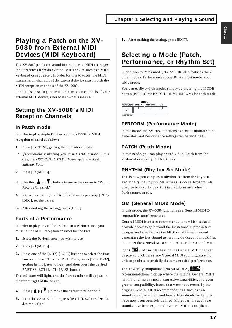
Selecting a Mode (Patch, Performance, or Rhythm Set) In addition to Patch mode, the XV-5080 also features three other modes: Performance mode, Rhythm Set mode, and GM2 mode.
You can easily switch modes simply by pressing the MODE button (PERFORM/PATCH/RHYTHM/GM) for each mode.fig.01-001.e
PERFORM (Performance Mode)In this mode, the XV-5080 functions as a multi-timbral sound generator, and Performance settings can be modified.
PATCH (Patch Mode)In this mode, you can play an individual Patch from the keyboard or modify Patch settings.
RHYTHM (Rhythm Set Mode)This is how you can play a Rhythm Set from the keyboard and modify the Rhythm Set settings. XV-5080 Rhythm Sets can also be used for any Part in a Performance when in Performance mode.
GM (General MIDI2 Mode)In this mode, the XV-5080 functions as a General MIDI 2-compatible sound generator.
General MIDI is a set of recommendations which seeks to provide a way to go beyond the limitations of proprietary designs, and standardize the MIDI capabilities of sound generating devices. Sound generating devices and music files that meet the General MIDI standard bear the General MIDI
logo ( ). Music files bearing the General MIDI logo can be played back using any General MIDI sound generating unit to produce essentially the same musical performance.
The upwardly compatible General MIDI 2 ( ) recommendations pick up where the original General MIDI left off, offering enhanced expressive capabilities, and even greater compatibility. Issues that were not covered by the original General MIDI recommendations, such as how sounds are to be edited, and how effects should be handled, have now been precisely defined. Moreover, the available sounds have been expanded. General MIDI 2 compliant
17
Chapter 1 Selecting and Playing a Sound
sound generators are capable of reliably playing back music files that carry either the General MIDI or General MIDI 2 logo. In some cases, the conventional form of General MIDI, which does not include the new enhancements, is referred to as “General MIDI 1” as a way of distinguishing it from General MIDI 2.
Patches, Rhythm Sets and Performances can be stored in the following memory locations within each library group.
PATCH RHYTHM PERFORM
USER 1–128 1, 2, 3, 4 1–64
CARD * * *
PR-A 1–128 1, 2 1–32
PR-B 1–128 1, 2 1–32
PR-C 1–128 1, 2 —
PR-D 1–128 1, 2 —
PR-E 1–128 1, 2 —
PR-F 1–128 1, 2 —
PR-G 1–128 1, 2 —
PR-H 1–256 1, 2, 3, 4 —
XP-A * * —
: : : :
XP-H * * —
–: None *: Differs by type
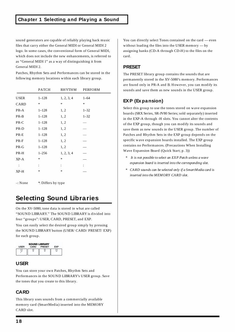
Selecting Sound LibrariesOn the XV-5080, tone data is stored in what are called “SOUND LIBRARY.” The SOUND LIBRARY is divided into four “groups”: USER, CARD, PRESET, and EXP.
You can easily select the desired group simply by pressing the SOUND LIBRARY button (USER/CARD/PRESET/EXP) for each group.fig.01-002.e
USERYou can store your own Patches, Rhythm Sets and Performances in the SOUND LIBRARY’s USER group. Save the tones that you create to this library.
CARDThis library uses sounds from a commercially available memory card (SmartMedia) inserted into the MEMORY CARD slot.
You can directly select Tones contained on the card — even without loading the files into the USER memory — by assigning banks (CD-A through CD-H) to the files on the card.
PRESETThe PRESET library group contains the sounds that are permanently stored in the XV-5080’s memory. Performances are found only in PR-A and B. However, you can modify its sounds and save them as new sounds in the USER group.
EXP (Expansion)Select this group to use the tones stored on wave expansion boards (SRX Series, SR-JV80 Series; sold separately) inserted in the EXP-A through -H slots. You cannot alter the contents of the EXP group, though you can modify its sounds and save them as new sounds in the USER group. The number of Patches and Rhythm Sets in the EXP group depends on the specific wave expansion boards installed. The EXP group contains no Performances. (Precautions When Installing Wave Expansion Board (Quick Start; p. 3))
* It is not possible to select an EXP Patch unless a wave
expansion board is inserted into the corresponding slot.
* CARD sounds can be selected only if a SmartMedia card is
inserted into the MEMORY CARD slot.
18
Chapter 1 Selecting and Playing a Sound
Chap.1
Selecting a Patch
Basic Procedure for Selecting a PatchTurn the VALUE dial or press [INC]/[DEC] to select the desired Patch.
VALUE DialTo move quickly through the available Patches:
Turn the VALUE dial while pressing it or, if you prefer, turn the VALUE dial while pressing [SHIFT].
[INC]/[DEC]To move quickly upward through the available Patches:
Hold down [INC] and press [DEC]. Alternatively, hold down [SHIFT] and press [INC].
To move quickly downward through the available
Patches:
Hold down [DEC] and press [INC]. Alternatively, hold down [SHIFT] and press [DEC].
When you hold down [INC] or [DEC], you may eventually arrive at the beginning (001) of the selected bank (A–H). To continue selecting Patches, release and then press the desired [INC] or [DEC] button again.
Selecting Patches by Category (Patch Finder)The XV-5080’s “Patch Finder” allows you to quickly find any Patch.
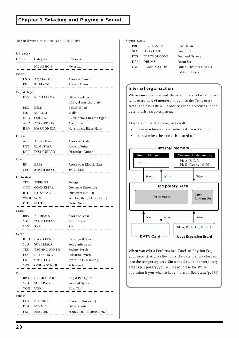
1. Press the [PATCH] button, lighting the indicator.
2. Press the [PATCH FINDER] button, lighting the indicator.
The categories will appear in the PATCH PLAY page.fig.01-003.e_70
You can press [ ]/[ ] to select the desired category.
At this point, you can select patches within the currently selected category, either by rotating the VALUE dial, or by using the [INC]/[DEC] button.
If you want to get even more information, carry out the following operation.
3. Press the VALUE dial.
The Group List window will appear.
4. Rotate the VALUE dial to select a group.
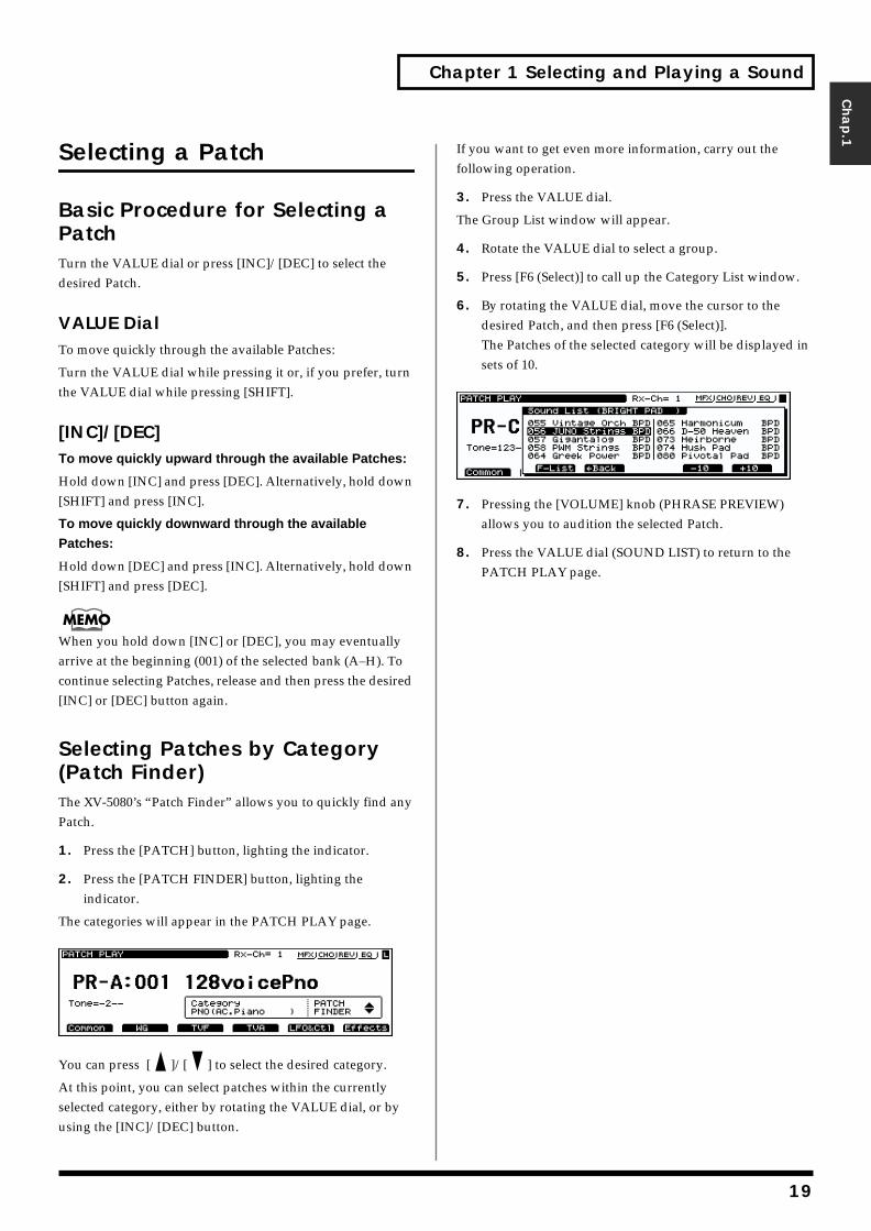
5. Press [F6 (Select)] to call up the Category List window.
6. By rotating the VALUE dial, move the cursor to the desired Patch, and then press [F6 (Select)].The Patches of the selected category will be displayed in sets of 10.
ig.01-003a.e_70
7. Pressing the [VOLUME] knob (PHRASE PREVIEW) allows you to audition the selected Patch.
8. Press the VALUE dial (SOUND LIST) to return to the PATCH PLAY page.
19
Chapter 1 Selecting and Playing a Sound
The following categories can be selected.
Category
Group Category Contents
— NO ASSIGN No assign
Piano
PNO AC.PIANO Acoustic Piano
EP EL.PIANO Electric Piano
Keys&Organ
KEY KEYBOARDS Other Keyboards
(Clav, Harpsichord etc.)
BEL BELL Bell, Bell Pad
MLT MALLET Mallet
ORG ORGAN Electric and Church Organ
ACD ACCORDION Accordion
HRM HARMONICA Harmonica, Blues Harp
Guitar
AGT AC.GUITAR Acoustic Guitar
EGT EL.GUITAR Electric Guitar
DGT DIST.GUITAR Distortion Guitar
Bass
BS BASS Acoustic & Electric Bass
SBS SYNTH BASS Synth Bass
Orchestral
STR STRINGS Strings
ORC ORCHESTRA Orchestra Ensemble
HIT HIT&STAB Orchestra Hit, Hit
WND WIND Winds (Oboe, Clarinet etc.)
FLT FLUTE Flute, Piccolo
Brass
BRS AC.BRASS Acoustic Brass
SBR SYNTH BRASS Synth Brass
SAX SAX Sax
Synth
HLD HARD LEAD Hard Synth Lead
SLD SOFT LEAD Soft Synth Lead
TEK TECHNO SYNTH Techno Synth
PLS PULSATING Pulsating Synth
FX SYNTH FX Synth FX (Noise etc.)
SYN OTHER SYNTH Poly Synth
Pad
BPD BRIGHT PAD Bright Pad Synth
SPD SOFT PAD Soft Pad Synth
VOX VOX Vox, Choir
Ethnic
PLK PLUCKED Plucked (Harp etc.)
ETH ETHNIC Other Ethnic
FRT FRETTED Fretted Inst (Mandolin etc.)
Rhythm&SFX
PRC PERCUSSION Percussion
SFX SOUND FX Sound FX
BTS BEAT&GROOVE Beat and Groove
DRM DRUMS Drum Set
CMB COMBINATION Other Patches which use
Split and Layer
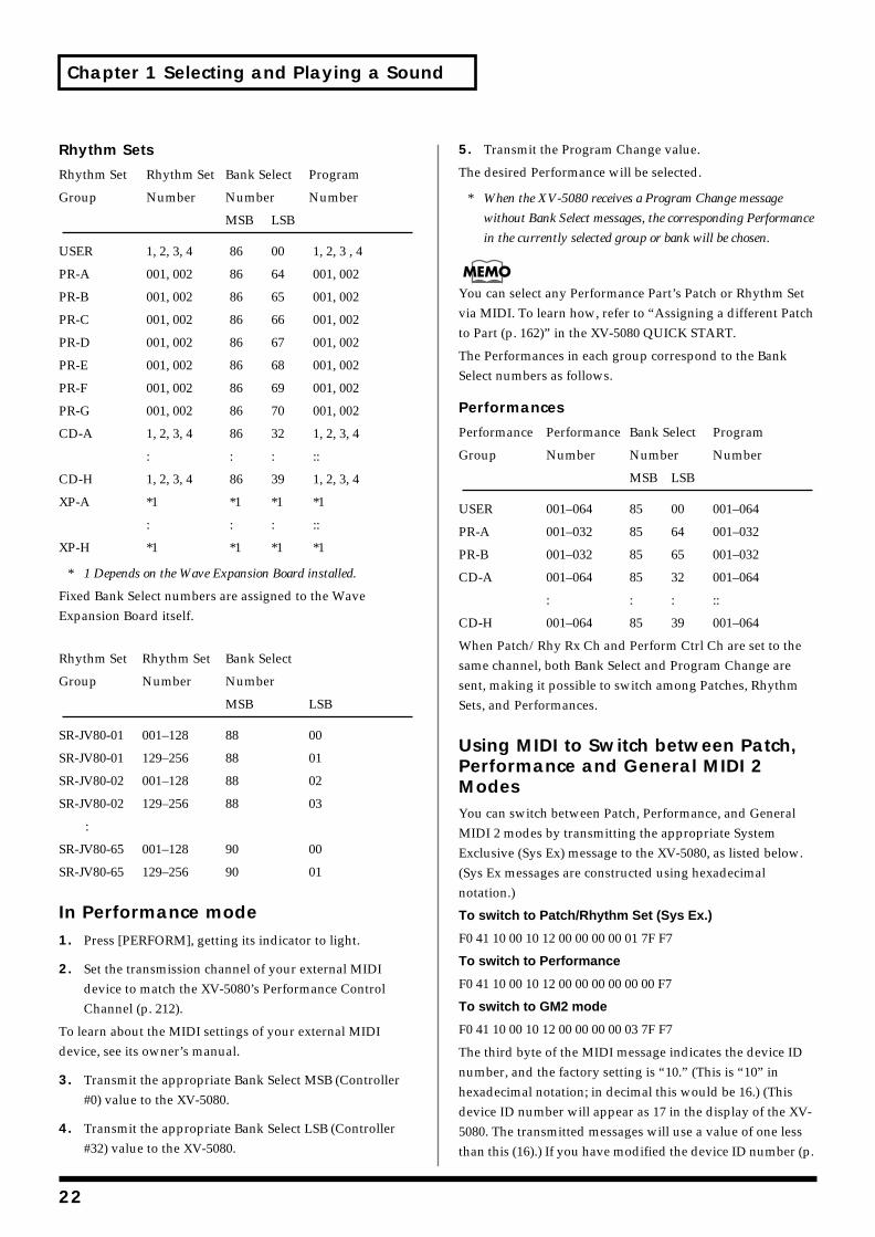
Internal organization
When you select a sound, the sound data is loaded into a temporary part of memory known as the Temporary Area. The XV-5080 will produce sound according to the data in this temporary area.
The data in the temporary area will
• change whenever you select a different sound.
• be lost when the power is turned off.
When you edit a Performance, Patch or Rhythm Set, your modifications affect only the data that was loaded into the temporary area. Since the data in the temporary area is temporary, you will need to use the Write operation if you wish to keep the modified data. (p. 194)
SelectSelect
SelectSelect
Write
Write
Rewritable memory
USER
XP-A, B, C, D, E, F, G, H
Non-rewritable memory
PR-A, B, C, EPR-D (General MIDI)
Internal Memory
DATA Card
PerformancePatchRhythm Set
Temporary Area
Wave Expansion Board
20
Chapter 1 Selecting and Playing a Sound
Chap.1
Selecting Patches and Rhythm Sets from an External MIDI DeviceBy receiving MIDI messages, the XV-5080 can switch Patches (including the Patches for each Part of a Performance) or Rhythm Sets.
In Patch or Rhythm Set modes1. Press [PATCH] — or [RHYTHM] if you wish to select a
Rhythm Set — to make the button’s indicator light.
2. Set the transmission channel of your external MIDI device to match Patch Receive Channel (p. 212), the XV-5080’s MIDI reception channel.
To learn about the MIDI settings of your external MIDI device, see its owner’s manual.
3. Transmit the appropriate Bank Select MSB (Controller #0) value to the XV-5080.
If the value is “87,” a Patch is selected. If the value is “86,” a Rhythm Set is selected.
4. Transmit the appropriate Bank Select LSB (Controller #32) value to the XV-5080.
5. Transmit the Program Change value corresponding to the Patch or Rhythm Set.
The desired Patch or Rhythm Set will be selected on the XV-5080.
* When the XV-5080 receives only Program Change messages
without receiving Bank Select messages, it will switch to the
corresponding Patch or Rhythm Set from the currently
selected group or bank.
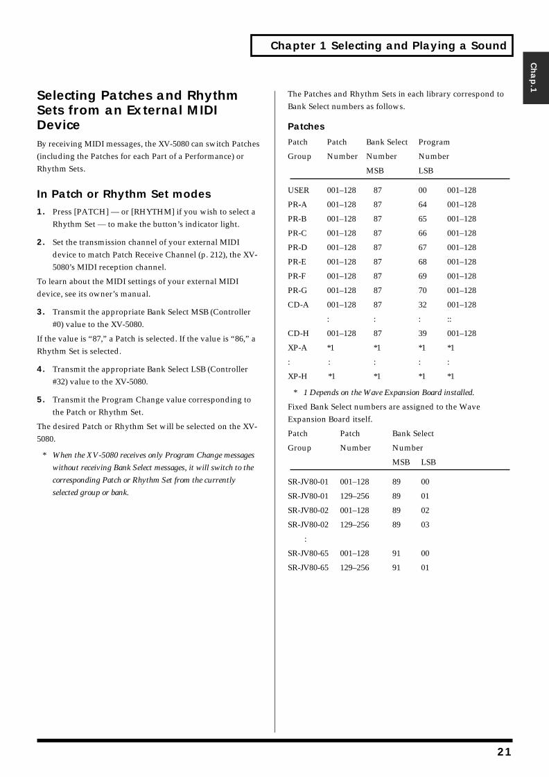
The Patches and Rhythm Sets in each library correspond to Bank Select numbers as follows.
Patches
Patch Patch Bank Select Program
Group Number Number Number
MSB LSB
USER 001–128 87 00 001–128
PR-A 001–128 87 64 001–128
PR-B 001–128 87 65 001–128
PR-C 001–128 87 66 001–128
PR-D 001–128 87 67 001–128
PR-E 001–128 87 68 001–128
PR-F 001–128 87 69 001–128
PR-G 001–128 87 70 001–128
CD-A 001–128 87 32 001–128
: : : ::
CD-H 001–128 87 39 001–128
XP-A *1 *1 *1 *1
: : : : :
XP-H *1 *1 *1 *1
* 1 Depends on the Wave Expansion Board installed.
Fixed Bank Select numbers are assigned to the Wave Expansion Board itself.
Patch Patch Bank Select
Group Number Number
MSB LSB
SR-JV80-01 001–128 89 00
SR-JV80-01 129–256 89 01
SR-JV80-02 001–128 89 02
SR-JV80-02 129–256 89 03
:
SR-JV80-65 001–128 91 00
SR-JV80-65 129–256 91 01
21
Chapter 1 Selecting and Playing a Sound
Rhythm Sets
Rhythm Set Rhythm Set Bank Select Program
Group Number Number Number
MSB LSB
USER 1, 2, 3, 4 86 00 1, 2, 3 , 4
PR-A 001, 002 86 64 001, 002
PR-B 001, 002 86 65 001, 002
PR-C 001, 002 86 66 001, 002
PR-D 001, 002 86 67 001, 002
PR-E 001, 002 86 68 001, 002
PR-F 001, 002 86 69 001, 002
PR-G 001, 002 86 70 001, 002
CD-A 1, 2, 3, 4 86 32 1, 2, 3, 4
: : : ::
CD-H 1, 2, 3, 4 86 39 1, 2, 3, 4
XP-A *1 *1 *1 *1
: : : ::
XP-H *1 *1 *1 *1
* 1 Depends on the Wave Expansion Board installed.
Fixed Bank Select numbers are assigned to the Wave Expansion Board itself.
Rhythm Set Rhythm Set Bank Select
Group Number Number
MSB LSB
SR-JV80-01 001–128 88 00
SR-JV80-01 129–256 88 01
SR-JV80-02 001–128 88 02
SR-JV80-02 129–256 88 03
:
SR-JV80-65 001–128 90 00
SR-JV80-65 129–256 90 01
In Performance mode1. Press [PERFORM], getting its indicator to light.
2. Set the transmission channel of your external MIDI device to match the XV-5080’s Performance Control Channel (p. 212).
To learn about the MIDI settings of your external MIDI device, see its owner’s manual.
3. Transmit the appropriate Bank Select MSB (Controller #0) value to the XV-5080.
4. Transmit the appropriate Bank Select LSB (Controller #32) value to the XV-5080.
5. Transmit the Program Change value.
The desired Performance will be selected.
* When the XV-5080 receives a Program Change message
without Bank Select messages, the corresponding Performance
in the currently selected group or bank will be chosen.
You can select any Performance Part’s Patch or Rhythm Set via MIDI. To learn how, refer to “Assigning a different Patch to Part (p. 162)” in the XV-5080 QUICK START.
The Performances in each group correspond to the Bank Select numbers as follows.
Performances
Performance Performance Bank Select Program
Group Number Number Number
MSB LSB
USER 001–064 85 00 001–064
PR-A 001–032 85 64 001–032
PR-B 001–032 85 65 001–032
CD-A 001–064 85 32 001–064
: : : ::
CD-H 001–064 85 39 001–064
When Patch/Rhy Rx Ch and Perform Ctrl Ch are set to the same channel, both Bank Select and Program Change are sent, making it possible to switch among Patches, Rhythm Sets, and Performances.
Using MIDI to Switch between Patch, Performance and General MIDI 2 ModesYou can switch between Patch, Performance, and General MIDI 2 modes by transmitting the appropriate System Exclusive (Sys Ex) message to the XV-5080, as listed below. (Sys Ex messages are constructed using hexadecimal notation.)
To switch to Patch/Rhythm Set (Sys Ex.)
F0 41 10 00 10 12 00 00 00 00 01 7F F7
To switch to Performance
F0 41 10 00 10 12 00 00 00 00 00 00 F7
To switch to GM2 mode
F0 41 10 00 10 12 00 00 00 00 03 7F F7
The third byte of the MIDI message indicates the device ID number, and the factory setting is “10.” (This is “10” in hexadecimal notation; in decimal this would be 16.) (This device ID number will appear as 17 in the display of the XV-5080. The transmitted messages will use a value of one less than this (16).) If you have modified the device ID number (p.
22
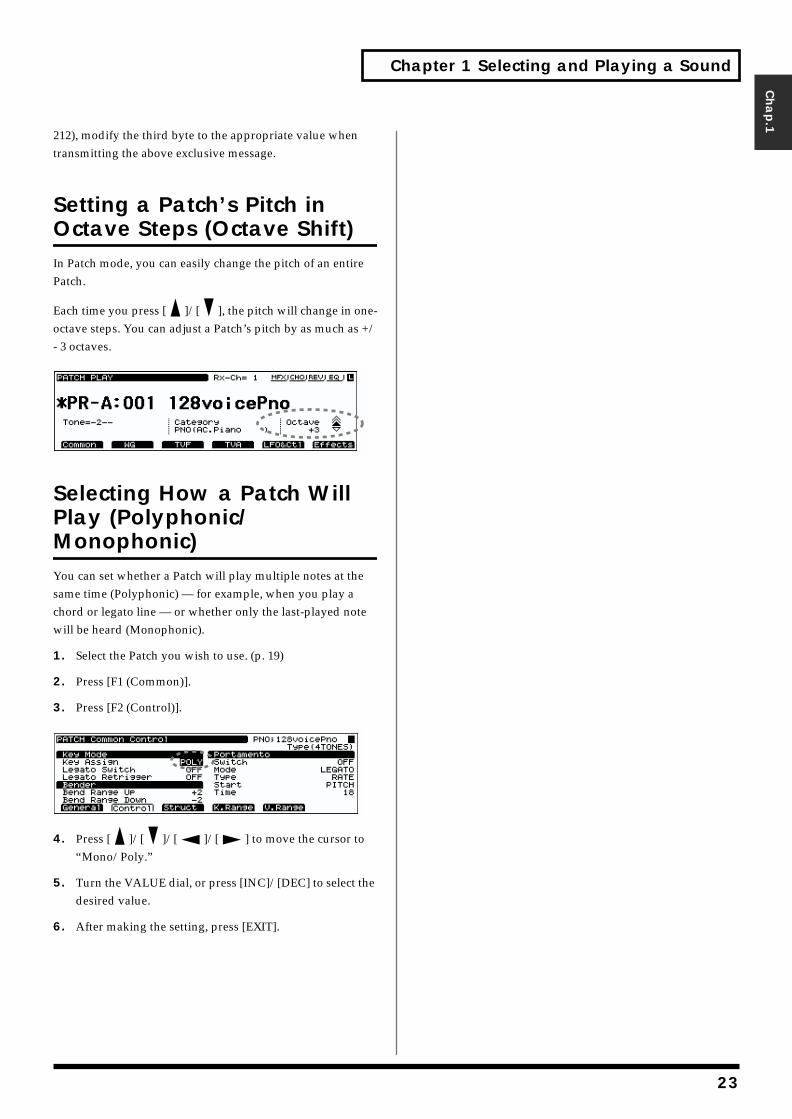
Chapter 1 Selecting and Playing a Sound
Chap.1
212), modify the third byte to the appropriate value when transmitting the above exclusive message.
Setting a Patch’s Pitch in Octave Steps (Octave Shift)In Patch mode, you can easily change the pitch of an entire Patch.
Each time you press [ ]/[ ], the pitch will change in one-octave steps. You can adjust a Patch’s pitch by as much as +/- 3 octaves.fig.01-004.e
Selecting How a Patch Will Play (Polyphonic/Monophonic)You can set whether a Patch will play multiple notes at the same time (Polyphonic) — for example, when you play a chord or legato line — or whether only the last-played note will be heard (Monophonic).
1. Select the Patch you wish to use. (p. 19)
2. Press [F1 (Common)].
3. Press [F2 (Control)].fig.01-005.e
4. Press [ ]/[ ]/[ ]/[ ] to move the cursor to “Mono/Poly.”
5. Turn the VALUE dial, or press [INC]/[DEC] to select the desired value.
6. After making the setting, press [EXIT].
23

2
Chapter 2 Using the XV-5080 Effects
The XV-5080 contains four independent effects units.
Multi-effects
The Multi-effects offers 90 different effects. In addition to effects consisting of only one effect, such as distortion and delay, the 90 types also include a number of compound effects, which are formed by combining a number of effects. Furthermore, the multi-effects effect types also include chorus and reverb, although the chorus and reverb described below can be applied as separate effects systems. The XV-5080 features three Multi-effects systems in Performance mode, with each multi-effect independently controllable.
Chorus
Chorus adds depth and spaciousness to the sound.
Reverb
Reverb adds ambience — such as the sound of a concert hall or auditorium—to sounds.
Equalizer
An equalizer lets you boost or cut specified frequency ranges of a sound to adjust the tone.
* Equalizer is set in System mode (p. 211).
Turning Effects On/OffYou can turn any of the XV-5080’s effect units—Multi-effects, Chorus, Reverb, and EQ—on or off using a single procedure.
1. Press the [EFFECTS ON/OFF] button.
The EFFECTS On/Off window will appear.fig.02-001.e_70
2. ress the [F2]–[F5] button corresponding to the effect to switch that effect on or off.
The display of the setting will be turned on and off.
3. Press the [EFFECTS ON/OFF] button, getting its indicator light to go out.
You might, for example, want to turn effects off when creating a new Patch so that you can hear what it sounds like without effects. You may also want to turn off the XV-5080’s effects when you wish to use external effect devices instead of the built-in effects.
Patch Mode SettingsYou can make separate Multi-effects, chorus, and reverb settings to each Four-Tone Patch and Multi-Partial Patch, with the same effects applied to each Tone or Partial. You can control the amount of effect to be applied to each Tone or Partial by adjusting its send level with respect to the Multi-effects, Chorus and Reverb.fig.02-002.e
fig.02-003.e
Preliminarily, the settings for effects involves determining Tone Output Assign for Four-Tone Patches, and Split Key Output Assign for Multi-Partial Patches.
In keeping with the intended usage, choose from the following setting values for Tone Output Assign.
MFX: Selected when the Multi-effects, chorus, and reverb are used.
A-D: Selected when outputting in stereo without use of the Multi-effects. Chorus and reverb can be used.
1-8: Selected when outputting in mono without Multi-effects. Chorus and reverb can be used. When this setting is used, chorus and reverb sounds are output in stereo according to the Chorus Output Assign and Reverb Output Assign settings.
Chorus
Reverb
TONE Multi-Effects
4 TONE Patch
Chorus
Reverb
Partial Multi-Effects
Multi-Partial Patch
88 Partials
A0
C8
4
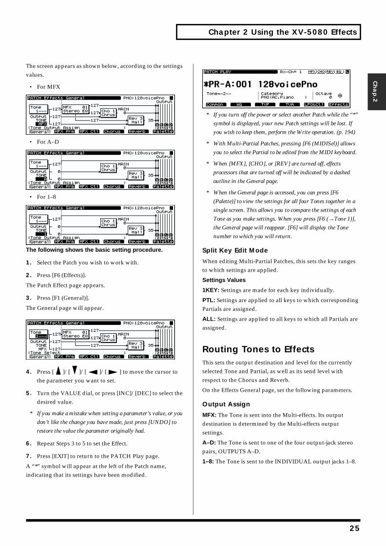
Chapter 2 Using the XV-5080 Effects
Chap.2
The screen appears as shown below, according to the settings values.
• For MFXfig.02-004.e_70
• For A–Dfig.02-005.e_70
• For 1–8fig.02-006.e_70
The following shows the basic setting procedure.
1. Select the Patch you wish to work with.
2. Press [F6 (Effects)].
The Patch Effect page appears.
3. Press [F1 (General)].
The General page will appear.fig.02-007.e_70
4. Press [ ]/[ ]/[ ]/[ ] to move the cursor to the parameter you want to set.
5. Turn the VALUE dial, or press [INC]/[DEC] to select the desired value.
* If you make a mistake when setting a parameter’s value, or you
don’t like the change you have made, just press [UNDO] to
restore the value the parameter originally had.
6. Repeat Steps 3 to 5 to set the Effect.
7. Press [EXIT] to return to the PATCH Play page.
A “*” symbol will appear at the left of the Patch name, indicating that its settings have been modified.
fig.02-008.e_70
* If you turn off the power or select another Patch while the “*”
symbol is displayed, your new Patch settings will be lost. If
you wish to keep them, perform the Write operation. (p. 194)
* With Multi-Partial Patches, pressing [F6 (MIDISel)] allows
you to select the Partial to be edited from the MIDI keyboard.
* When [MFX], [CHO], or [REV] are turned off, effects
processors that are turned off will be indicated by a dashed
outline in the General page.
* When the General page is accessed, you can press [F6
(Palette)] to view the settings for all four Tones together in a
single screen. This allows you to compare the settings of each
Tone as you make settings. When you press [F6 (→Tone 1)],
the General page will reappear. [F6] will display the Tone
number to which you will return.
Split Key Edit Mode
When editing Multi-Partial Patches, this sets the key ranges to which settings are applied.
Settings Values
1KEY: Settings are made for each key individually.
PTL: Settings are applied to all keys to which corresponding Partials are assigned.
ALL: Settings are applied to all keys to which all Partials are assigned.
Routing Tones to EffectsThis sets the output destination and level for the currently selected Tone and Partial, as well as its send level with respect to the Chorus and Reverb.
On the Effects General page, set the following parameters.
Output Assign
MFX: The Tone is sent into the Multi-effects. Its output destination is determined by the Multi-effects output settings.
A–D: The Tone is sent to one of the four output-jack stereo pairs, OUTPUTS A–D.
1–8: The Tone is sent to the INDIVIDUAL output jacks 1–8.
25
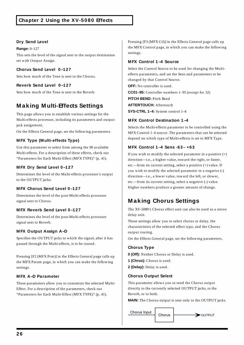
Chapter 2 Using the XV-5080 Effects
Dry Send Level
Range: 0–127
This sets the level of the signal sent to the output destination set with Output Assign.
Chorus Send Level 0–127
Sets how much of the Tone is sent to the Chorus.
Reverb Send Level 0–127
Sets how much of the Tone is sent to the Reverb.
Making Multi-Effects SettingsThis page allows you to establish various settings for the Multi-effects processor, including its parameters and output-jack assignment.
On the Effects General page, set the following parameters.
MFX Type (Multi-effects Type)
Use this parameter to select from among the 90 available Multi-effects. For a description of these effects, check out “Parameters for Each Multi-Effect (MFX TYPE)” (p. 41).
MFX Dry Send Level 0–127
Determines the level of the Multi-effects processor’s output to the OUTPUT jacks.
MFX Chorus Send Level 0–127
Determines the level of the post-Multi-effects processor signal sent to Chorus.
MFX Reverb Send Level 0–127
Determines the level of the post-Multi-effects processor signal sent to Reverb.
MFX Output Assign A–D
Specifies the OUTPUT jacks to which the signal, after it has passed through the Multi-effects, is to be routed.
Pressing [F2 (MFX Prm)] in the Effects General page calls up the MFX Param page, in which you can make the following settings.
MFX A–D Parameter
These parameters allow you to customize the selected Multi-Effect. For a description of the parameters, check out “Parameters for Each Multi-Effect (MFX TYPE)” (p. 41).
Pressing [F3 (MFX Ctl)] in the Effects General page calls up the MFX Control page, in which you can make the following settings.
MFX Control 1–4 Source
Select the Control Source to be used for changing the Multi-effects parameters, and set the Sens and parameters to be changed by that Control Source.
OFF: No controller is used.
CC01–95: Controller numbers 1–95 (except for 32)
PITCH BEND: Pitch Bend
AFTERTOUCH: Aftertouch
SYS-CTRL 1–4: System control 1–4
MFX Control Destination 1–4
Selects the Multi-effects parameter to be controlled using the MFX Control 1–4 source. The parameters that can be selected depend on which type of Multi-effects is set to MFX Type.
MFX Control 1–4 Sens -63– +63
If you wish to modify the selected parameter in a positive (+) direction—i.e., a higher value, toward the right, or faster, etc.—from its current setting, select a positive (+) value. If you wish to modify the selected parameter in a negative (-) direction—i.e., a lower value, toward the left, or slower, etc.—from its current setting, select a negative (-) value. Higher numbers produce a greater amount of change.
Making Chorus SettingsThe XV-5080’s Chorus effect unit can also be used as a stereo delay unit.
These settings allow you to select chorus or delay, the characteristics of the selected effect type, and the Chorus output routing.
On the Effects General page, set the following parameters.
Chorus Type
0 (Off): Neither Chorus or Delay is used.
1 (Chrus): Chorus is used.
2 (Delay): Delay is used.
Chorus Output Select
This parameter allows you to send the Chorus output directly to the currently selected OUTPUT jacks, to the Reverb, or to both.
MAIN: The Chorus output is sent only to the OUTPUT jacks.fig.02-009.e
OUTPUT
26
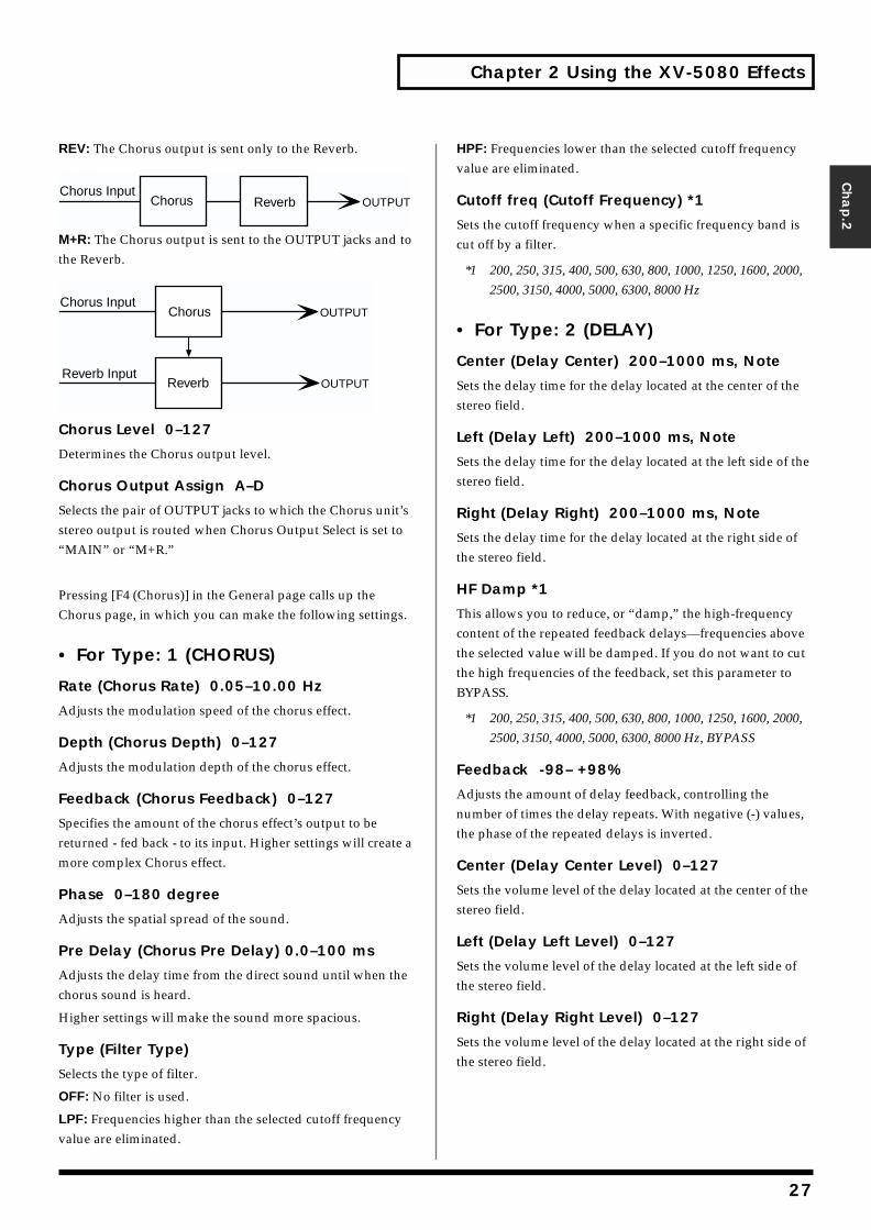
Chapter 2 Using the XV-5080 Effects
Chap.2
REV: The Chorus output is sent only to the Reverb.fig.02-010.e
M+R: The Chorus output is sent to the OUTPUT jacks and to the Reverb.fig.02-011.e
Chorus Level 0–127
Determines the Chorus output level.
Chorus Output Assign A–D
Selects the pair of OUTPUT jacks to which the Chorus unit’s stereo output is routed when Chorus Output Select is set to “MAIN” or “M+R.”
Pressing [F4 (Chorus)] in the General page calls up the Chorus page, in which you can make the following settings.
• For Type: 1 (CHORUS)
Rate (Chorus Rate) 0.05–10.00 Hz
Adjusts the modulation speed of the chorus effect.
Depth (Chorus Depth) 0–127
Adjusts the modulation depth of the chorus effect.
Feedback (Chorus Feedback) 0–127
Specifies the amount of the chorus effect’s output to be returned - fed back - to its input. Higher settings will create a more complex Chorus effect.
Phase 0–180 degree
Adjusts the spatial spread of the sound.
Pre Delay (Chorus Pre Delay) 0.0–100 ms
Adjusts the delay time from the direct sound until when the chorus sound is heard.
Higher settings will make the sound more spacious.
Type (Filter Type)
Selects the type of filter.
OFF: No filter is used.
LPF: Frequencies higher than the selected cutoff frequency value are eliminated.
HPF: Frequencies lower than the selected cutoff frequency value are eliminated.
Cutoff freq (Cutoff Frequency) *1
Sets the cutoff frequency when a specific frequency band is cut off by a filter.
*1 200, 250, 315, 400, 500, 630, 800, 1000, 1250, 1600, 2000,
2500, 3150, 4000, 5000, 6300, 8000 Hz
• For Type: 2 (DELAY)
Center (Delay Center) 200–1000 ms, Note
Sets the delay time for the delay located at the center of the stereo field.
Left (Delay Left) 200–1000 ms, Note
Sets the delay time for the delay located at the left side of the stereo field.
Right (Delay Right) 200–1000 ms, Note
Sets the delay time for the delay located at the right side of the stereo field.
HF Damp *1
This allows you to reduce, or “damp,” the high-frequency content of the repeated feedback delays—frequencies above the selected value will be damped. If you do not want to cut the high frequencies of the feedback, set this parameter to BYPASS.
*1 200, 250, 315, 400, 500, 630, 800, 1000, 1250, 1600, 2000,
2500, 3150, 4000, 5000, 6300, 8000 Hz, BYPASS
Feedback -98– +98%
Adjusts the amount of delay feedback, controlling the number of times the delay repeats. With negative (-) values, the phase of the repeated delays is inverted.
Center (Delay Center Level) 0–127
Sets the volume level of the delay located at the center of the stereo field.
Left (Delay Left Level) 0–127
Sets the volume level of the delay located at the left side of the stereo field.
Right (Delay Right Level) 0–127
Sets the volume level of the delay located at the right side of the stereo field.
OUTPUTChorus Input
Chorus Reverb
OUTPUT
OUTPUT
Chorus Input
Reverb Input
Chorus
Reverb
27
Chapter 2 Using the XV-5080 Effects
Making Reverb SettingsThese settings allow you to select the desired type of Reverb, its characteristics, and the pair of OUTPUT jacks to which the Reverb unit’s stereo output is routed.
On the Effects General page, set the following parameters.
Reverb Type
Selects the type of Reverb.
0 (Off): Reverb is not used.
1 (Revrb): Normal Reverb
2 (Room): This reverb simulates typical room acoustic reflections.
3 (Hall): This reverb simulates typical concert hall acoustic reflections.
4 (Plate): This reverb simulates a reverb plate, a popular type of artificial reverb unit that derives its sound from the vibration of a metallic plate. You can also achieve unusual metallic-sounding reverbs using SRV PLATE.
Reverb Level 0–127
Specifies the output level of the Reverb.
Reverb Output Assign A–D
Selects the OUTPUT jacks to which the Reverb unit’s stereo output is routed.
Pressing [F5 (Reverb)] in the General page calls up the Reverb page, in which you can make the following settings.
• For Type: 1 (REVERB)
Type (Reverb/Delay Type)
Selects a type of reverb or delay.
ROOM1: This is a short reverb with high density.
ROOM2: This is a short reverb with low density.
STAGE1: This is a reverb with greater late reverberation.
STAGE2: This is a reverb with strong early reflections.
HALL1: This is a very clear-sounding reverb.
HALL2: This is a rich reverb.
DELAY: This is a conventional delay effect.
PAN-DELAY: This is a delay effect with echoes that pan left and right.
Time (Reverb/Delay Time) 0–127
When the Type setting is ROOM1–HALL2, this adjusts the length of reverberation. When the Type setting is DELAY or PAN-DELAY, this adjusts the delay time.
Higher settings produce a more spacious ambience.
HF Damp (Reverb/Delay HF Damp) *1
Specifies the frequency above which the high-frequency content of the reverb sound will be cut, or “damped.”
Lower values cause a greater range of high frequencies to be cut, producing a softer reverb sound. If you do not want to cut the high frequencies of the feedback, set this parameter to BYPASS.
*1 200, 250, 315, 400, 500, 630, 800, 1000, 1250, 1600, 2000,
2500, 3150, 4000, 5000, 6300, 8000 Hz, BYPASS
Feedback (Delay Feedback)
When the Type setting is DELAY or PAN-DELAY, this adjust the amount of delay feedback, controlling the number of delay repeats.
Higher settings will produce more delay repeats.
• For Type: 2 (SRV ROOM)/3 (SRV HALL)/4 (SRV PLATE)
Pre Delay (Pre Delay Time) 0.0–100 ms
Adjusts the time delay from when the direct sound begins until the reverb sound is heard.
Time (Reverb Time) 0–127
Adjusts the time length of reverberation.
Size 1–8
Adjusts the size of the simulated room or hall. The size becomes bigger as the value increases.
High Cut (High Cut Frequency) *1
Sets the frequency above which the high-frequency content of the reverb will be reduced. If you do not want to damp the high frequencies, set this parameter to BYPASS.
Density (Reverb Density) 0–127
Adjusts the density of reverb. Higher values result in greater density.
Diffusion (Reverb Diffusion) 0–127
Adjusts the change in the density of the reverb over time. The higher the value, the more the density increases with time. (The effect of this setting is most pronounced with long reverb times.)
LF Damp Freq (LF Damp Frequency) *2
Specifies the frequency below which the low-frequency content of the reverb sound will be reduced, or “damped.”
28

Chapter 2 Using the XV-5080 Effects
Chap.2
LF Damp Gain -36–0 dB
Adjusts the amount of damping applied to the frequency range selected with LF Damp. With a setting of “0,” there will be no reduction of the reverb’s low-frequency content.
HF Damp Freq (LF Damp Frequency) *3
Specifies the frequency above which the high-frequency content of the reverb sound will be reduced, or “damped.”
HF Damp Gain -36–0 dB
Adjusts the amount of damping applied to the frequency range selected with HF Damp. With a setting of “0,” there will be no reduction of the reverb’s high-frequency content.
*1 160, 200, 250, 320, 400, 500, 640, 800, 1000, 1250, 1600,
2000, 2500, 3200, 4000, 5000, 6400, 8000, 10000, 12500
Hz, BYPASS
*2 50, 64, 80, 100, 125, 160, 200, 250, 320, 400, 500, 640, 800,
1000, 1250, 1600, 2000, 2500, 3200, 4000 Hz
*3 4000, 5000, 6400, 8000, 10000, 12500 Hz
29
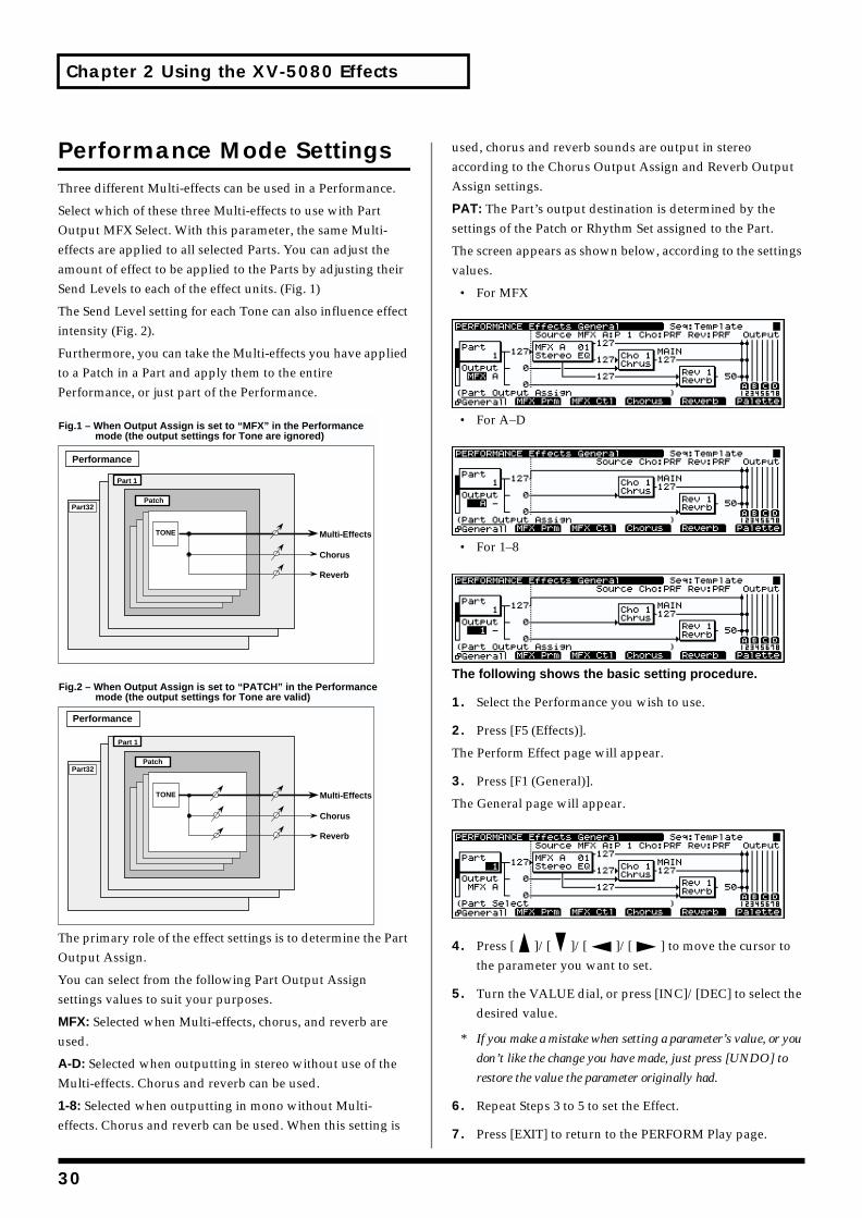
Chapter 2 Using the XV-5080 Effects
Performance Mode SettingsThree different Multi-effects can be used in a Performance.
Select which of these three Multi-effects to use with Part Output MFX Select. With this parameter, the same Multi-effects are applied to all selected Parts. You can adjust the amount of effect to be applied to the Parts by adjusting their Send Levels to each of the effect units. (Fig. 1)
The Send Level setting for each Tone can also influence effect intensity (Fig. 2).
Furthermore, you can take the Multi-effects you have applied to a Patch in a Part and apply them to the entire Performance, or just part of the Performance.fig.02-012.e
fig.02-013.e
The primary role of the effect settings is to determine the Part Output Assign.
You can select from the following Part Output Assign settings values to suit your purposes.
MFX: Selected when Multi-effects, chorus, and reverb are used.
A-D: Selected when outputting in stereo without use of the Multi-effects. Chorus and reverb can be used.
1-8: Selected when outputting in mono without Multi-effects. Chorus and reverb can be used. When this setting is
used, chorus and reverb sounds are output in stereo according to the Chorus Output Assign and Reverb Output Assign settings.
PAT: The Part’s output destination is determined by the settings of the Patch or Rhythm Set assigned to the Part.
The screen appears as shown below, according to the settings values.
• For MFXfig.02-014.e_70
• For A–Dfig.02-015.e_70
• For 1–8fig.02-016.e_70
The following shows the basic setting procedure.
1. Select the Performance you wish to use.
2. Press [F5 (Effects)].
The Perform Effect page will appear.
3. Press [F1 (General)].
The General page will appear.fig.02-017.e_70
4. Press [ ]/[ ]/[ ]/[ ] to move the cursor to the parameter you want to set.
5. Turn the VALUE dial, or press [INC]/[DEC] to select the desired value.
* If you make a mistake when setting a parameter’s value, or you
don’t like the change you have made, just press [UNDO] to
restore the value the parameter originally had.
6. Repeat Steps 3 to 5 to set the Effect.
7. Press [EXIT] to return to the PERFORM Play page.
Performance
Part32
Chorus
Reverb
TONE Multi-Effects
Patch
Part 1
Fig.1 – When Output Assign is set to “MFX” in the Performance mode (the output settings for Tone are ignored)
Performance
Part32
Fig.2 – When Output Assign is set to “PATCH” in the Performance mode (the output settings for Tone are valid)
TONE
Patch
Part 1
Chorus
Reverb
Multi-Effects
30
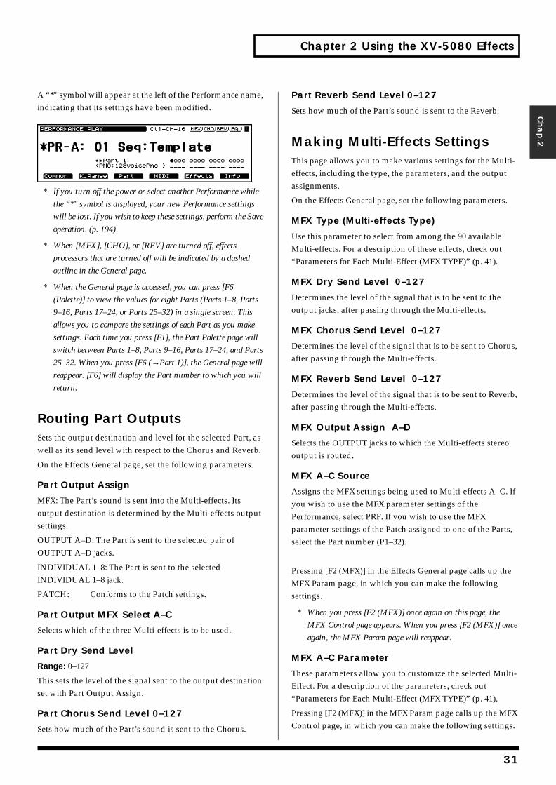
Chapter 2 Using the XV-5080 Effects
Chap.2
A “*” symbol will appear at the left of the Performance name, indicating that its settings have been modified.fig.02-018.e_70
* If you turn off the power or select another Performance while
the “*” symbol is displayed, your new Performance settings
will be lost. If you wish to keep these settings, perform the Save
operation. (p. 194)
* When [MFX], [CHO], or [REV] are turned off, effects
processors that are turned off will be indicated by a dashed
outline in the General page.
* When the General page is accessed, you can press [F6
(Palette)] to view the values for eight Parts (Parts 1–8, Parts
9–16, Parts 17–24, or Parts 25–32) in a single screen. This
allows you to compare the settings of each Part as you make
settings. Each time you press [F1], the Part Palette page will
switch between Parts 1–8, Parts 9–16, Parts 17–24, and Parts
25–32. When you press [F6 (→Part 1)], the General page will
reappear. [F6] will display the Part number to which you will
return.
Routing Part OutputsSets the output destination and level for the selected Part, as well as its send level with respect to the Chorus and Reverb.
On the Effects General page, set the following parameters.
Part Output Assign
MFX: The Part’s sound is sent into the Multi-effects. Its output destination is determined by the Multi-effects output settings.
OUTPUT A–D: The Part is sent to the selected pair of OUTPUT A–D jacks.
INDIVIDUAL 1–8: The Part is sent to the selected INDIVIDUAL 1–8 jack.
PATCH: Conforms to the Patch settings.
Part Output MFX Select A–C
Selects which of the three Multi-effects is to be used.
Part Dry Send Level
Range: 0–127
This sets the level of the signal sent to the output destination set with Part Output Assign.
Part Chorus Send Level 0–127
Sets how much of the Part’s sound is sent to the Chorus.
Part Reverb Send Level 0–127
Sets how much of the Part’s sound is sent to the Reverb.
Making Multi-Effects SettingsThis page allows you to make various settings for the Multi-effects, including the type, the parameters, and the output assignments.
On the Effects General page, set the following parameters.
MFX Type (Multi-effects Type)
Use this parameter to select from among the 90 available Multi-effects. For a description of these effects, check out “Parameters for Each Multi-Effect (MFX TYPE)” (p. 41).
MFX Dry Send Level 0–127
Determines the level of the signal that is to be sent to the output jacks, after passing through the Multi-effects.
MFX Chorus Send Level 0–127
Determines the level of the signal that is to be sent to Chorus, after passing through the Multi-effects.
MFX Reverb Send Level 0–127
Determines the level of the signal that is to be sent to Reverb, after passing through the Multi-effects.
MFX Output Assign A–D
Selects the OUTPUT jacks to which the Multi-effects stereo output is routed.
MFX A–C Source
Assigns the MFX settings being used to Multi-effects A–C. If you wish to use the MFX parameter settings of the Performance, select PRF. If you wish to use the MFX parameter settings of the Patch assigned to one of the Parts, select the Part number (P1–32).
Pressing [F2 (MFX)] in the Effects General page calls up the MFX Param page, in which you can make the following settings.
* When you press [F2 (MFX)] once again on this page, the
MFX Control page appears. When you press [F2 (MFX)] once
again, the MFX Param page will reappear.
MFX A–C Parameter
These parameters allow you to customize the selected Multi-Effect. For a description of the parameters, check out “Parameters for Each Multi-Effect (MFX TYPE)” (p. 41).
Pressing [F2 (MFX)] in the MFX Param page calls up the MFX Control page, in which you can make the following settings.
31
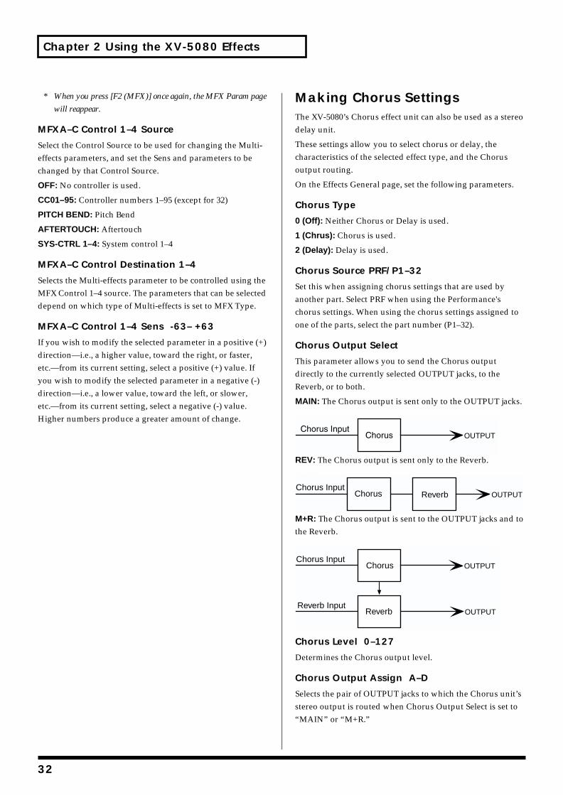
Chapter 2 Using the XV-5080 Effects
* When you press [F2 (MFX)] once again, the MFX Param page
will reappear.
MFXA–C Control 1–4 Source
Select the Control Source to be used for changing the Multi-effects parameters, and set the Sens and parameters to be changed by that Control Source.
OFF: No controller is used.
CC01–95: Controller numbers 1–95 (except for 32)
PITCH BEND: Pitch Bend
AFTERTOUCH: Aftertouch
SYS-CTRL 1–4: System control 1–4
MFXA–C Control Destination 1–4
Selects the Multi-effects parameter to be controlled using the MFX Control 1–4 source. The parameters that can be selected depend on which type of Multi-effects is set to MFX Type.
MFXA–C Control 1–4 Sens -63– +63
If you wish to modify the selected parameter in a positive (+) direction—i.e., a higher value, toward the right, or faster, etc.—from its current setting, select a positive (+) value. If you wish to modify the selected parameter in a negative (-) direction—i.e., a lower value, toward the left, or slower, etc.—from its current setting, select a negative (-) value. Higher numbers produce a greater amount of change.
Making Chorus SettingsThe XV-5080’s Chorus effect unit can also be used as a stereo delay unit.
These settings allow you to select chorus or delay, the characteristics of the selected effect type, and the Chorus output routing.
On the Effects General page, set the following parameters.
Chorus Type
0 (Off): Neither Chorus or Delay is used.
1 (Chrus): Chorus is used.
2 (Delay): Delay is used.
Chorus Source PRF/P1–32
Set this when assigning chorus settings that are used by another part. Select PRF when using the Performance's chorus settings. When using the chorus settings assigned to one of the parts, select the part number (P1–32).
Chorus Output Select
This parameter allows you to send the Chorus output directly to the currently selected OUTPUT jacks, to the Reverb, or to both.
MAIN: The Chorus output is sent only to the OUTPUT jacks.fig.02-019.e
REV: The Chorus output is sent only to the Reverb.fig.02-020.e
M+R: The Chorus output is sent to the OUTPUT jacks and to the Reverb.fig.02-021.e
Chorus Level 0–127
Determines the Chorus output level.
Chorus Output Assign A–D
Selects the pair of OUTPUT jacks to which the Chorus unit’s stereo output is routed when Chorus Output Select is set to “MAIN” or “M+R.”
OUTPUT
OUTPUTChorus Input
Chorus Reverb
OUTPUT
OUTPUT
Chorus Input
Reverb Input
Chorus
Reverb
32
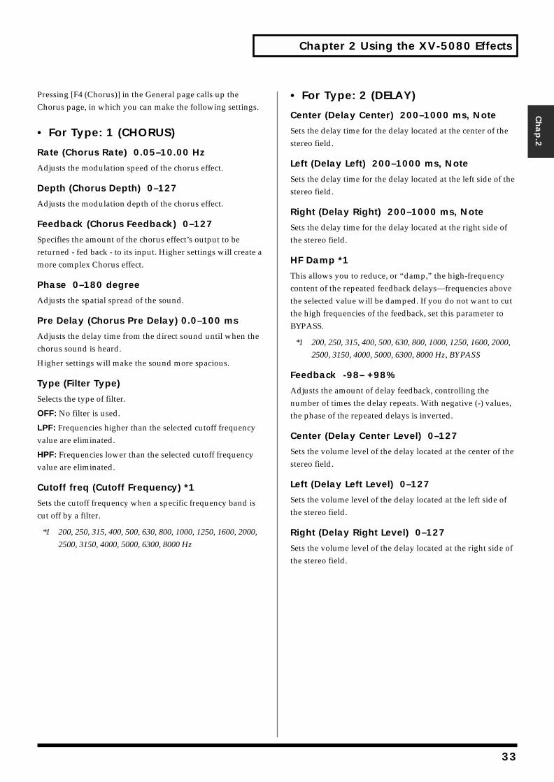
Chapter 2 Using the XV-5080 Effects
Chap.2
Pressing [F4 (Chorus)] in the General page calls up the Chorus page, in which you can make the following settings.
• For Type: 1 (CHORUS)
Rate (Chorus Rate) 0.05–10.00 Hz
Adjusts the modulation speed of the chorus effect.
Depth (Chorus Depth) 0–127
Adjusts the modulation depth of the chorus effect.
Feedback (Chorus Feedback) 0–127
Specifies the amount of the chorus effect’s output to be returned - fed back - to its input. Higher settings will create a more complex Chorus effect.
Phase 0–180 degree
Adjusts the spatial spread of the sound.
Pre Delay (Chorus Pre Delay) 0.0–100 ms
Adjusts the delay time from the direct sound until when the chorus sound is heard.
Higher settings will make the sound more spacious.
Type (Filter Type)
Selects the type of filter.
OFF: No filter is used.
LPF: Frequencies higher than the selected cutoff frequency value are eliminated.
HPF: Frequencies lower than the selected cutoff frequency value are eliminated.
Cutoff freq (Cutoff Frequency) *1
Sets the cutoff frequency when a specific frequency band is cut off by a filter.
*1 200, 250, 315, 400, 500, 630, 800, 1000, 1250, 1600, 2000,
2500, 3150, 4000, 5000, 6300, 8000 Hz
• For Type: 2 (DELAY)
Center (Delay Center) 200–1000 ms, Note
Sets the delay time for the delay located at the center of the stereo field.
Left (Delay Left) 200–1000 ms, Note
Sets the delay time for the delay located at the left side of the stereo field.
Right (Delay Right) 200–1000 ms, Note
Sets the delay time for the delay located at the right side of the stereo field.
HF Damp *1
This allows you to reduce, or “damp,” the high-frequency content of the repeated feedback delays—frequencies above the selected value will be damped. If you do not want to cut the high frequencies of the feedback, set this parameter to BYPASS.
*1 200, 250, 315, 400, 500, 630, 800, 1000, 1250, 1600, 2000,
2500, 3150, 4000, 5000, 6300, 8000 Hz, BYPASS
Feedback -98– +98%
Adjusts the amount of delay feedback, controlling the number of times the delay repeats. With negative (-) values, the phase of the repeated delays is inverted.
Center (Delay Center Level) 0–127
Sets the volume level of the delay located at the center of the stereo field.
Left (Delay Left Level) 0–127
Sets the volume level of the delay located at the left side of the stereo field.
Right (Delay Right Level) 0–127
Sets the volume level of the delay located at the right side of the stereo field.
33
Chapter 2 Using the XV-5080 Effects
Making Reverb SettingsThese settings allow you to select the desired type of Reverb, its characteristics, and the pair of OUTPUT jacks to which the Reverb unit’s stereo output is routed.
On the Effects General page, set the following parameters.
Reverb Type
Selects the type of Reverb.
0 (Off): Reverb is not used.
1 (Revrb): Normal Reverb
2 (Room): This reverb simulates typical room acoustic reflections.
3 (Hall): This reverb simulates typical concert hall acoustic reflections.
4 (Plate): This reverb simulates a reverb plate, a popular type of artificial reverb unit that derives its sound from the vibration of a metallic plate. You can also achieve unusual metallic-sounding reverbs using SRV PLATE.
Reverb Source
Set this when assigning reverb settings that are used by another part. Select PRF when using the Performance's reverb settings. When using the reverb settings assigned to one of the parts, select the part number (P1–32).
Reverb Level 0–127
Specifies the output level of the Reverb.
Reverb Output Assign A–D
Selects the OUTPUT jacks to which the Reverb unit’s stereo output is routed.
Pressing [F5 (Reverb)] in the General page calls up the Reverb page, in which you can make the following settings.
• For Type: 1 (REVERB)
Type (Reverb/Delay Type)
Selects a type of reverb or delay.
ROOM1: This is a short reverb with high density.
ROOM2: This is a short reverb with low density.
STAGE1: This is a reverb with greater late reverberation.
STAGE2: This is a reverb with strong early reflections.
HALL1: This is a very clear-sounding reverb.
HALL2: This is a rich reverb.
DELAY: This is a conventional delay effect.
PAN-DELAY: This is a delay effect with echoes that pan left and right.
Time (Reverb/Delay Time) 0–127
When the Type setting is ROOM1–HALL2, this adjusts the length of reverberation. When the Type setting is DELAY or PAN-DELAY, this adjusts the delay time.
Higher settings produce a more spacious ambience.
HF Damp (Reverb/Delay HF Damp) *1
Specifies the frequency above which the high-frequency content of the reverb sound will be cut, or “damped.”
Lower values cause a greater range of high frequencies to be cut, producing a softer reverb sound. If you do not want to cut the high frequencies of the feedback, set this parameter to BYPASS.
*1 200, 250, 315, 400, 500, 630, 800, 1000, 1250, 1600, 2000,
2500, 3150, 4000, 5000, 6300, 8000 Hz, BYPASS
Feedback (Delay Feedback)
When the Type setting is DELAY or PAN-DELAY, this adjust the amount of delay feedback, controlling the number of delay repeats.
Higher settings will produce more delay repeats.
34
Chapter 2 Using the XV-5080 Effects
Chap.2
• For Type: 2 (SRV ROOM)/3 (SRV HALL)/4 (SRV PLATE)
Pre Delay (Pre Delay Time) 0.0–100 ms
Adjusts the time delay from when the direct sound begins until the reverb sound is heard.
Time (Reverb Time) 0–127
Adjusts the time length of reverberation.
Size 1–8
Adjusts the size of the simulated room or hall. The size becomes bigger as the value increases.
High Cut (High Cut Frequency) *1
Sets the frequency above which the high-frequency content of the reverb will be reduced. If you do not want to damp the high frequencies, set this parameter to BYPASS.
Density (Reverb Density) 0–127
Adjusts the density of reverb. Higher values result in greater density.
Diffusion (Reverb Diffusion) 0–127
Adjusts the change in the density of the reverb over time. The higher the value, the more the density increases with time. (The effect of this setting is most pronounced with long reverb times.)
LF Damp Freq (LF Damp Frequency) *2
Specifies the frequency below which the low-frequency content of the reverb sound will be reduced, or “damped.”
LF Damp Gain -36–0 dB
Adjusts the amount of damping applied to the frequency range selected with LF Damp. With a setting of “0,” there will be no reduction of the reverb’s low-frequency content.
HF Damp Freq (LF Damp Frequency) *3
Specifies the frequency above which the high-frequency content of the reverb sound will be reduced, or “damped.”
HF Damp Gain -36–0 dB
Adjusts the amount of damping applied to the frequency range selected with HF Damp. With a setting of “0,” there will be no reduction of the reverb’s high-frequency content.
*1 160, 200, 250, 320, 400, 500, 640, 800, 1000, 1250, 1600,
2000, 2500, 3200, 4000, 5000, 6400, 8000, 10000, 12500
Hz, BYPASS
*2 50, 64, 80, 100, 125, 160, 200, 250, 320, 400, 500, 640, 800,
1000, 1250, 1600, 2000, 2500, 3200, 4000 Hz
*3 4000, 5000, 6400, 8000, 10000, 12500 Hz
35
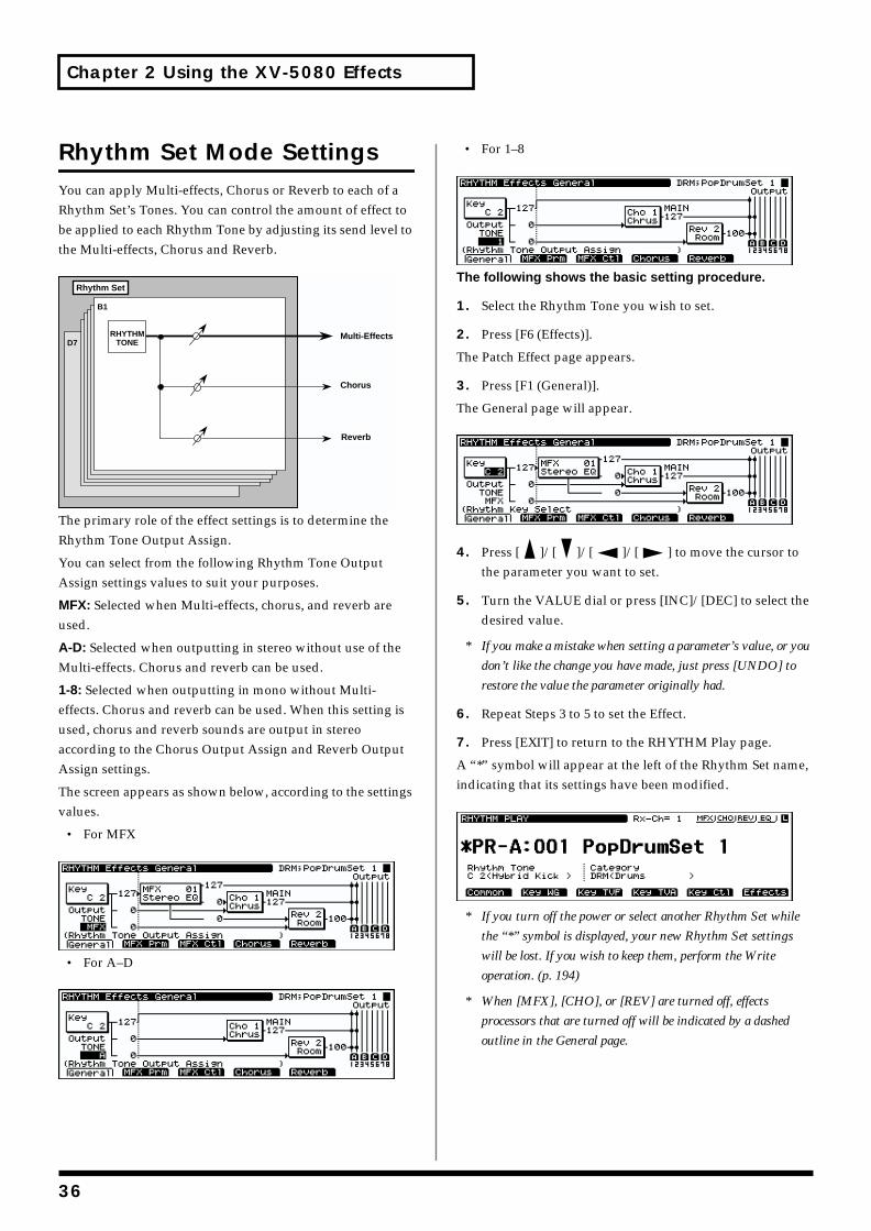
Chapter 2 Using the XV-5080 Effects
Rhythm Set Mode SettingsYou can apply Multi-effects, Chorus or Reverb to each of a Rhythm Set’s Tones. You can control the amount of effect to be applied to each Rhythm Tone by adjusting its send level to the Multi-effects, Chorus and Reverb.fig.02-022.e
The primary role of the effect settings is to determine the Rhythm Tone Output Assign.
You can select from the following Rhythm Tone Output Assign settings values to suit your purposes.
MFX: Selected when Multi-effects, chorus, and reverb are used.
A-D: Selected when outputting in stereo without use of the Multi-effects. Chorus and reverb can be used.
1-8: Selected when outputting in mono without Multi-effects. Chorus and reverb can be used. When this setting is used, chorus and reverb sounds are output in stereo according to the Chorus Output Assign and Reverb Output Assign settings.
The screen appears as shown below, according to the settings values.
• For MFXfig.02-023.e_70
• For A–Dfig.02-024.e_70
• For 1–8fig.02-025.e_70
The following shows the basic setting procedure.
1. Select the Rhythm Tone you wish to set.
2. Press [F6 (Effects)].
The Patch Effect page appears.
3. Press [F1 (General)].
The General page will appear.fig.02-026.e_70
4. Press [ ]/[ ]/[ ]/[ ] to move the cursor to the parameter you want to set.
5. Turn the VALUE dial or press [INC]/[DEC] to select the desired value.
* If you make a mistake when setting a parameter’s value, or you
don’t like the change you have made, just press [UNDO] to
restore the value the parameter originally had.
6. Repeat Steps 3 to 5 to set the Effect.
7. Press [EXIT] to return to the RHYTHM Play page.
A “*” symbol will appear at the left of the Rhythm Set name, indicating that its settings have been modified.fig.02-027.e_70
* If you turn off the power or select another Rhythm Set while
the “*” symbol is displayed, your new Rhythm Set settings
will be lost. If you wish to keep them, perform the Write
operation. (p. 194)
* When [MFX], [CHO], or [REV] are turned off, effects
processors that are turned off will be indicated by a dashed
outline in the General page.
Chorus
Reverb
RHYTHMTONE
Multi-Effects
Rhythm Set
B1
D7
36
Chapter 2 Using the XV-5080 Effects
Chap.2
Routing Tones to EffectsThis sets the output destination and level for the currently selected Tone, as well as its send level with respect to the Chorus and Reverb.
On the Effects General page, set the following parameters.
Rhythm Tone Output Assign
MFX: The Tone is sent into the Multi-effects. Its output destination is determined by the Multi-effects output settings.
A–D: The Tone is sent to one of the four output-jack stereo pairs, OUTPUTS A–D.
1–8: The Tone is sent to the INDIVIDUAL output jacks 1–8.
Rhythm Tone Dry Send Level
Range: 0–127
This sets the level of the signal sent to the output destination set with Rhythm Output Assign.
Rhythm Tone Chorus Send Level 0–127
Sets how much of the Tone is sent to the Chorus.
Rhythm Tone Reverb Send Level 0–127
Sets how much of the Tone is sent to the Reverb.
Making Multi-Effects SettingsThis page allows you to make various settings for the Multi-effects, including the type, the parameters, and the output assignments
On the Effects General page, set the following parameters.
MFX Type (Multi-effects Type)
Use this parameter to select from among the 90 available Multi-effects. For a description of these effects, check out “Parameters for Each Multi-Effect (MFX TYPE)” (p. 41).
MFX Dry Send Level 0–127
Determines the level of the signal that is to be sent to the output jacks, after passing through the Multi-effects.
MFX Chorus Send Level 0–127
Determines the level of the signal that is to be sent to Chorus, after passing through the Multi-effects.
MFX Reverb Send Level 0–127
Determines the level of the signal that is to be sent to Reverb, after passing through the Multi-effects.
MFX Output Assign A–D
Specifies the OUTPUT jacks to which the signal, after it has passed through the Multi-effects, is to be routed.
Pressing [F2 (MFX Prm)] in the Effects General page calls up the MFX Param page, in which you can make the following settings.
MFX A–C Parameters
These parameters allow you to customize the selected Multi-Effect. For a description of the parameters, check out “Parameters for Each Multi-Effect (MFX TYPE)” (p. 41).
Pressing [F3 (MFX Ctl)] in the Effects General page calls up the MFX Control page, in which you can make the following settings.
MFX Control 1–4 Source
Select the Control Source to be used for changing the Multi-effects parameters, and set the Sens and parameters to be changed by that Control Source.
OFF: No controller is used.
CC01–95: Controller numbers 1–95 (except for 32)
PITCH BEND: Pitch Bend
AFTERTOUCH: Aftertouch
SYS-CTRL 1–4: System control 1–4
MFX Control Destination 1–4
Selects the Multi-effects parameter to be controlled using the MFX Control 1–4 source. The parameters that can be selected depend on which type of Multi-effects is set to MFX Type.
MFX Control 1–4 Sens -63– +63
If you wish to modify the selected parameter in a positive (+) direction—i.e., a higher value, toward the right, or faster, etc.—from its current setting, select a positive (+) value. If you wish to modify the selected parameter in a negative (-) direction—i.e., a lower value, toward the left, or slower, etc.—from its current setting, select a negative (-) value. Higher numbers produce a greater amount of change.
37
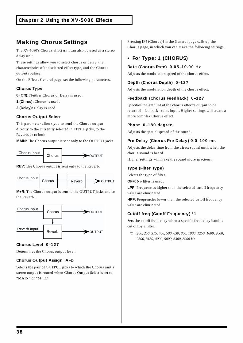
Chapter 2 Using the XV-5080 Effects
Making Chorus SettingsThe XV-5080’s Chorus effect unit can also be used as a stereo delay unit.
These settings allow you to select chorus or delay, the characteristics of the selected effect type, and the Chorus output routing.
On the Effects General page, set the following parameters.
Chorus Type
0 (Off): Neither Chorus or Delay is used.
1 (Chrus): Chorus is used.
2 (Delay): Delay is used.
Chorus Output Select
This parameter allows you to send the Chorus output directly to the currently selected OUTPUT jacks, to the Reverb, or to both.
MAIN: The Chorus output is sent only to the OUTPUT jacks.fig.02-028.e
REV: The Chorus output is sent only to the Reverb.fig.02-029.e
M+R: The Chorus output is sent to the OUTPUT jacks and to the Reverb.fig.02-030.e
Chorus Level 0–127
Determines the Chorus output level.
Chorus Output Assign A–D
Selects the pair of OUTPUT jacks to which the Chorus unit’s stereo output is routed when Chorus Output Select is set to “MAIN” or “M+R.”
Pressing [F4 (Chorus)] in the General page calls up the Chorus page, in which you can make the following settings.
• For Type: 1 (CHORUS)
Rate (Chorus Rate) 0.05–10.00 Hz
Adjusts the modulation speed of the chorus effect.
Depth (Chorus Depth) 0–127
Adjusts the modulation depth of the chorus effect.
Feedback (Chorus Feedback) 0–127
Specifies the amount of the chorus effect’s output to be returned - fed back - to its input. Higher settings will create a more complex Chorus effect.
Phase 0–180 degree
Adjusts the spatial spread of the sound.
Pre Delay (Chorus Pre Delay) 0.0–100 ms
Adjusts the delay time from the direct sound until when the chorus sound is heard.
Higher settings will make the sound more spacious.
Type (Filter Type)
Selects the type of filter.
OFF: No filter is used.
LPF: Frequencies higher than the selected cutoff frequency value are eliminated.
HPF: Frequencies lower than the selected cutoff frequency value are eliminated.
Cutoff freq (Cutoff Frequency) *1
Sets the cutoff frequency when a specific frequency band is cut off by a filter.
*1 200, 250, 315, 400, 500, 630, 800, 1000, 1250, 1600, 2000,
2500, 3150, 4000, 5000, 6300, 8000 Hz
OUTPUT
OUTPUTChorus Input
Chorus Reverb
OUTPUT
OUTPUT
Chorus Input
Reverb Input
Chorus
Reverb
38
Chapter 2 Using the XV-5080 Effects
Chap.2
• For Type: 2 (DELAY)
Center (Delay Center) 200–1000 ms, Note
Sets the delay time for the delay located at the center of the stereo field.
Left (Delay Left) 200–1000 ms, Note
Sets the delay time for the delay located at the left side of the stereo field.
Right (Delay Right) 200–1000 ms, Note
Sets the delay time for the delay located at the right side of the stereo field.
HF Damp *1
This allows you to reduce, or “damp,” the high-frequency content of the repeated feedback delays—frequencies above the selected value will be damped. If you do not want to cut the high frequencies of the feedback, set this parameter to BYPASS.
*1 200, 250, 315, 400, 500, 630, 800, 1000, 1250, 1600, 2000,
2500, 3150, 4000, 5000, 6300, 8000 Hz, BYPASS
Feedback -98– +98%
Adjusts the amount of delay feedback, controlling the number of times the delay repeats. With negative (-) values, the phase of the repeated delays is inverted.
Center (Delay Center Level) 0–127
Sets the volume level of the delay located at the center of the stereo field.
Left (Delay Left Level) 0–127
Sets the volume level of the delay located at the left side of the stereo field.
Right (Delay Right Level) 0–127
Sets the volume level of the delay located at the right side of the stereo field.
Making Reverb SettingsThese settings allow you to select the desired type of Reverb, its characteristics, and the pair of OUTPUT jacks to which the Reverb unit’s stereo output is routed.
On the Effects General page, set the following parameters.
Reverb Type
Selects the type of Reverb.
0 (Off): Reverb is not used.
1 (Revrb): Normal Reverb
2 (Room): This reverb simulates typical room acoustic reflections.
3 (Hall): This reverb simulates typical concert hall acoustic reflections.
4 (Plate): This reverb simulates a reverb plate, a popular type of artificial reverb unit that derives its sound from the vibration of a metallic plate. You can also achieve unusual metallic-sounding reverbs using SRV PLATE.
Reverb Level 0–127
Specifies the output level of the Reverb.
Reverb Output Assign A–D
Selects the OUTPUT jacks to which the Reverb unit’s stereo output is routed.
Pressing [F5 (Reverb)] in the General page calls up the Reverb page, in which you can make the following settings.
39
Chapter 2 Using the XV-5080 Effects
• For Type: 1 (REVERB)
Type (Reverb/Delay Type)
Selects a type of reverb or delay.
ROOM1: This is a short reverb with high density.
ROOM2: This is a short reverb with low density.
STAGE1: This is a reverb with greater late reverberation.
STAGE2: This is a reverb with strong early reflections.
HALL1: This is a very clear-sounding reverb.
HALL2: This is a rich reverb.
DELAY: This is a conventional delay effect.
PAN-DELAY: This is a delay effect with echoes that pan left and right.
Time (Reverb/Delay Time) 0–127
When the Type setting is ROOM1–HALL2, this adjusts the length of reverberation. When the Type setting is DELAY or PAN-DELAY, this adjusts the delay time.
Higher settings produce a more spacious ambience.
HF Damp (Reverb/Delay HF Damp) *1
Specifies the frequency above which the high-frequency content of the reverb sound will be cut, or “damped.”
Lower values cause a greater range of high frequencies to be cut, producing a softer reverb sound. If you do not want to cut the high frequencies of the feedback, set this parameter to BYPASS.
*1 200, 250, 315, 400, 500, 630, 800, 1000, 1250, 1600, 2000,
2500, 3150, 4000, 5000, 6300, 8000 Hz, BYPASS
Feedback (Delay Feedback)
When the Type setting is DELAY or PAN-DELAY, this adjust the amount of delay feedback, controlling the number of delay repeats.
Higher settings will produce more delay repeats.
• For Type: 2 (SRV ROOM)/3 (SRV HALL)/4 (SRV PLATE)
Pre Delay (Pre Delay Time) 0.0–100 ms
Adjusts the time delay from when the direct sound begins until the reverb sound is heard.
Time (Reverb Time) 0–127
Adjusts the time length of reverberation.
Size 1–8
Adjusts the size of the simulated room or hall. The size becomes bigger as the value increases.
High Cut (High Cut Frequency) *1
Sets the frequency above which the high-frequency content of the reverb will be reduced. If you do not want to damp the high frequencies, set this parameter to BYPASS.
Density (Reverb Density) 0–127
Adjusts the density of reverb. Higher values result in greater density.
Diffusion (Reverb Diffusion) 0–127
Adjusts the change in the density of the reverb over time. The higher the value, the more the density increases with time. (The effect of this setting is most pronounced with long reverb times.)
LF Damp Freq (LF Damp Frequency) *2
Specifies the frequency below which the low-frequency content of the reverb sound will be reduced, or “damped.”
LF Damp Gain -36–0 dB
Adjusts the amount of damping applied to the frequency range selected with LF Damp. With a setting of “0,” there will be no reduction of the reverb’s low-frequency content.
HF Damp Freq (LF Damp Frequency) *3
Specifies the frequency above which the high-frequency content of the reverb sound will be reduced, or “damped.”
HF Damp Gain -36–0 dB
Adjusts the amount of damping applied to the frequency range selected with HF Damp. With a setting of “0,” there will be no reduction of the reverb’s high-frequency content.
*1 160, 200, 250, 320, 400, 500, 640, 800, 1000, 1250, 1600,
2000, 2500, 3200, 4000, 5000, 6400, 8000, 10000, 12500
Hz, BYPASS
*2 50, 64, 80, 100, 125, 160, 200, 250, 320, 400, 500, 640, 800,
1000, 1250, 1600, 2000, 2500, 3200, 4000 Hz
*3 4000, 5000, 6400, 8000, 10000, 12500 Hz
40
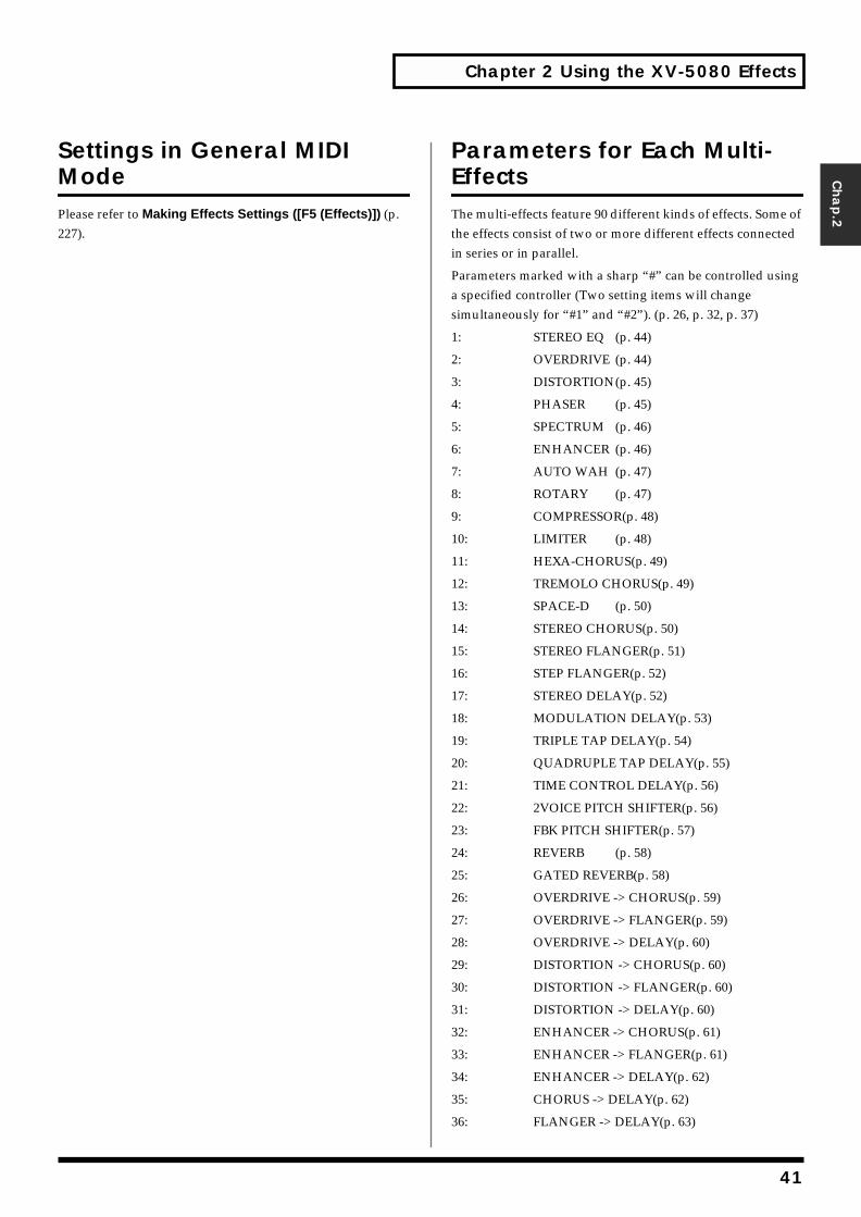
Chapter 2 Using the XV-5080 Effects
Chap.2
Settings in General MIDI ModePlease refer to Making Effects Settings ([F5 (Effects)]) (p. 227).
Parameters for Each Multi-EffectsThe multi-effects feature 90 different kinds of effects. Some of the effects consist of two or more different effects connected in series or in parallel.
Parameters marked with a sharp “#” can be controlled using a specified controller (Two setting items will change simultaneously for “#1” and “#2”). (p. 26, p. 32, p. 37)
1: STEREO EQ (p. 44)
2: OVERDRIVE (p. 44)
3: DISTORTION(p. 45)
4: PHASER (p. 45)
5: SPECTRUM (p. 46)
6: ENHANCER (p. 46)
7: AUTO WAH (p. 47)
8: ROTARY (p. 47)
9: COMPRESSOR(p. 48)
10: LIMITER (p. 48)
11: HEXA-CHORUS(p. 49)
12: TREMOLO CHORUS(p. 49)
13: SPACE-D (p. 50)
14: STEREO CHORUS(p. 50)
15: STEREO FLANGER(p. 51)
16: STEP FLANGER(p. 52)
17: STEREO DELAY(p. 52)
18: MODULATION DELAY(p. 53)
19: TRIPLE TAP DELAY(p. 54)
20: QUADRUPLE TAP DELAY(p. 55)
21: TIME CONTROL DELAY(p. 56)
22: 2VOICE PITCH SHIFTER(p. 56)
23: FBK PITCH SHIFTER(p. 57)
24: REVERB (p. 58)
25: GATED REVERB(p. 58)
26: OVERDRIVE -> CHORUS(p. 59)
27: OVERDRIVE -> FLANGER(p. 59)
28: OVERDRIVE -> DELAY(p. 60)
29: DISTORTION -> CHORUS(p. 60)
30: DISTORTION -> FLANGER(p. 60)
31: DISTORTION -> DELAY(p. 60)
32: ENHANCER -> CHORUS(p. 61)
33: ENHANCER -> FLANGER(p. 61)
34: ENHANCER -> DELAY(p. 62)
35: CHORUS -> DELAY(p. 62)
36: FLANGER -> DELAY(p. 63)
41
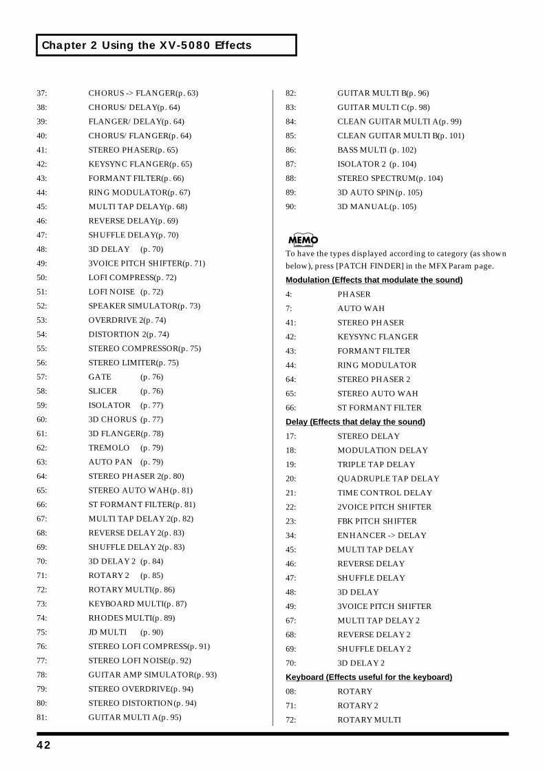
Chapter 2 Using the XV-5080 Effects
37: CHORUS -> FLANGER(p. 63)
38: CHORUS/DELAY(p. 64)
39: FLANGER/DELAY(p. 64)
40: CHORUS/FLANGER(p. 64)
41: STEREO PHASER(p. 65)
42: KEYSYNC FLANGER(p. 65)
43: FORMANT FILTER(p. 66)
44: RING MODULATOR(p. 67)
45: MULTI TAP DELAY(p. 68)
46: REVERSE DELAY(p. 69)
47: SHUFFLE DELAY(p. 70)
48: 3D DELAY (p. 70)
49: 3VOICE PITCH SHIFTER(p. 71)
50: LOFI COMPRESS(p. 72)
51: LOFI NOISE (p. 72)
52: SPEAKER SIMULATOR(p. 73)
53: OVERDRIVE 2(p. 74)
54: DISTORTION 2(p. 74)
55: STEREO COMPRESSOR(p. 75)
56: STEREO LIMITER(p. 75)
57: GATE (p. 76)
58: SLICER (p. 76)
59: ISOLATOR (p. 77)
60: 3D CHORUS (p. 77)
61: 3D FLANGER(p. 78)
62: TREMOLO (p. 79)
63: AUTO PAN (p. 79)
64: STEREO PHASER 2(p. 80)
65: STEREO AUTO WAH(p. 81)
66: ST FORMANT FILTER(p. 81)
67: MULTI TAP DELAY 2(p. 82)
68: REVERSE DELAY 2(p. 83)
69: SHUFFLE DELAY 2(p. 83)
70: 3D DELAY 2 (p. 84)
71: ROTARY 2 (p. 85)
72: ROTARY MULTI(p. 86)
73: KEYBOARD MULTI(p. 87)
74: RHODES MULTI(p. 89)
75: JD MULTI (p. 90)
76: STEREO LOFI COMPRESS(p. 91)
77: STEREO LOFI NOISE(p. 92)
78: GUITAR AMP SIMULATOR(p. 93)
79: STEREO OVERDRIVE(p. 94)
80: STEREO DISTORTION(p. 94)
81: GUITAR MULTI A(p. 95)
82: GUITAR MULTI B(p. 96)
83: GUITAR MULTI C(p. 98)
84: CLEAN GUITAR MULTI A(p. 99)
85: CLEAN GUITAR MULTI B(p. 101)
86: BASS MULTI (p. 102)
87: ISOLATOR 2 (p. 104)
88: STEREO SPECTRUM(p. 104)
89: 3D AUTO SPIN(p. 105)
90: 3D MANUAL(p. 105)
To have the types displayed according to category (as shown below), press [PATCH FINDER] in the MFX Param page.
Modulation (Effects that modulate the sound)
4: PHASER
7: AUTO WAH
41: STEREO PHASER
42: KEYSYNC FLANGER
43: FORMANT FILTER
44: RING MODULATOR
64: STEREO PHASER 2
65: STEREO AUTO WAH
66: ST FORMANT FILTER
Delay (Effects that delay the sound)
17: STEREO DELAY
18: MODULATION DELAY
19: TRIPLE TAP DELAY
20: QUADRUPLE TAP DELAY
21: TIME CONTROL DELAY
22: 2VOICE PITCH SHIFTER
23: FBK PITCH SHIFTER
34: ENHANCER -> DELAY
45: MULTI TAP DELAY
46: REVERSE DELAY
47: SHUFFLE DELAY
48: 3D DELAY
49: 3VOICE PITCH SHIFTER
67: MULTI TAP DELAY 2
68: REVERSE DELAY 2
69: SHUFFLE DELAY 2
70: 3D DELAY 2
Keyboard (Effects useful for the keyboard)
08: ROTARY
71: ROTARY 2
72: ROTARY MULTI
42
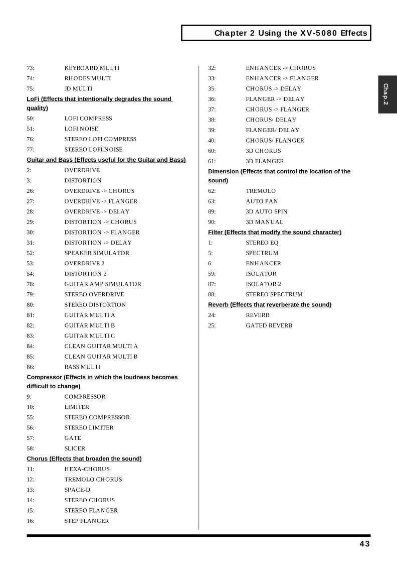
Chapter 2 Using the XV-5080 Effects
Chap.2
73: KEYBOARD MULTI
74: RHODES MULTI
75: JD MULTI
LoFi (Effects that intentionally degrades the sound
quality)
50: LOFI COMPRESS
51: LOFI NOISE
76: STEREO LOFI COMPRESS
77: STEREO LOFI NOISE
Guitar and Bass (Effects useful for the Guitar and Bass)
2: OVERDRIVE
3: DISTORTION
26: OVERDRIVE -> CHORUS
27: OVERDRIVE -> FLANGER
28: OVERDRIVE -> DELAY
29: DISTORTION -> CHORUS
30: DISTORTION -> FLANGER
31: DISTORTION -> DELAY
52: SPEAKER SIMULATOR
53: OVERDRIVE 2
54: DISTORTION 2
78: GUITAR AMP SIMULATOR
79: STEREO OVERDRIVE
80: STEREO DISTORTION
81: GUITAR MULTI A
82: GUITAR MULTI B
83: GUITAR MULTI C
84: CLEAN GUITAR MULTI A
85: CLEAN GUITAR MULTI B
86: BASS MULTI
Compressor (Effects in which the loudness becomes
difficult to change)
9: COMPRESSOR
10: LIMITER
55: STEREO COMPRESSOR
56: STEREO LIMITER
57: GATE
58: SLICER
Chorus (Effects that broaden the sound)
11: HEXA-CHORUS
12: TREMOLO CHORUS
13: SPACE-D
14: STEREO CHORUS
15: STEREO FLANGER
16: STEP FLANGER
32: ENHANCER -> CHORUS
33: ENHANCER -> FLANGER
35: CHORUS -> DELAY
36: FLANGER -> DELAY
37: CHORUS -> FLANGER
38: CHORUS/DELAY
39: FLANGER/DELAY
40: CHORUS/FLANGER
60: 3D CHORUS
61: 3D FLANGER
Dimension (Effects that control the location of the
sound)
62: TREMOLO
63: AUTO PAN
89: 3D AUTO SPIN
90: 3D MANUAL
Filter (Effects that modify the sound character)
1: STEREO EQ
5: SPECTRUM
6: ENHANCER
59: ISOLATOR
87: ISOLATOR 2
88: STEREO SPECTRUM
Reverb (Effects that reverberate the sound)
24: REVERB
25: GATED REVERB
43
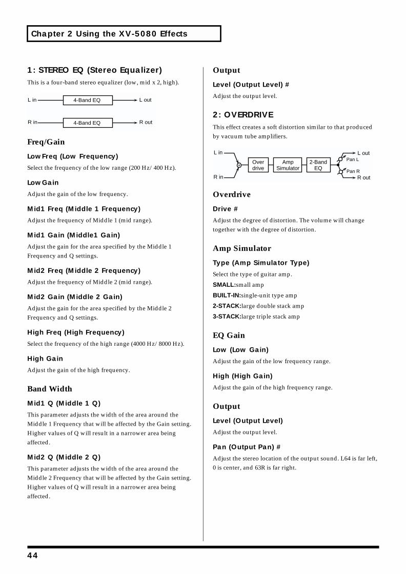
Chapter 2 Using the XV-5080 Effects
1: STEREO EQ (Stereo Equalizer)This is a four-band stereo equalizer (low, mid x 2, high).fig.2-04
Freq/Gain
LowFreq (Low Frequency)
Select the frequency of the low range (200 Hz/400 Hz).
LowGain
Adjust the gain of the low frequency.
Mid1 Freq (Middle 1 Frequency)
Adjust the frequency of Middle 1 (mid range).
Mid1 Gain (Middle1 Gain)
Adjust the gain for the area specified by the Middle 1 Frequency and Q settings.
Mid2 Freq (Middle 2 Frequency)
Adjust the frequency of Middle 2 (mid range).
Mid2 Gain (Middle 2 Gain)
Adjust the gain for the area specified by the Middle 2 Frequency and Q settings.
High Freq (High Frequency)
Select the frequency of the high range (4000 Hz/8000 Hz).
High Gain
Adjust the gain of the high frequency.
Band Width
Mid1 Q (Middle 1 Q)
This parameter adjusts the width of the area around the Middle 1 Frequency that will be affected by the Gain setting. Higher values of Q will result in a narrower area being affected.
Mid2 Q (Middle 2 Q)
This parameter adjusts the width of the area around the Middle 2 Frequency that will be affected by the Gain setting. Higher values of Q will result in a narrower area being affected.
Output
Level (Output Level) #
Adjust the output level.
2: OVERDRIVEThis effect creates a soft distortion similar to that produced by vacuum tube amplifiers.fig.2-05
Overdrive
Drive #
Adjust the degree of distortion. The volume will change together with the degree of distortion.
Amp Simulator
Type (Amp Simulator Type)
Select the type of guitar amp.
SMALL:small amp
BUILT-IN:single-unit type amp
2-STACK:large double stack amp
3-STACK:large triple stack amp
EQ Gain
Low (Low Gain)
Adjust the gain of the low frequency range.
High (High Gain)
Adjust the gain of the high frequency range.
Output
Level (Output Level)
Adjust the output level.
Pan (Output Pan) #
Adjust the stereo location of the output sound. L64 is far left, 0 is center, and 63R is far right.
L in
R in
L out
R out
4-Band EQ
4-Band EQ
AmpSimulator
2-BandEQ
L in
R in
Overdrive
L out
R outPan R
Pan L
44
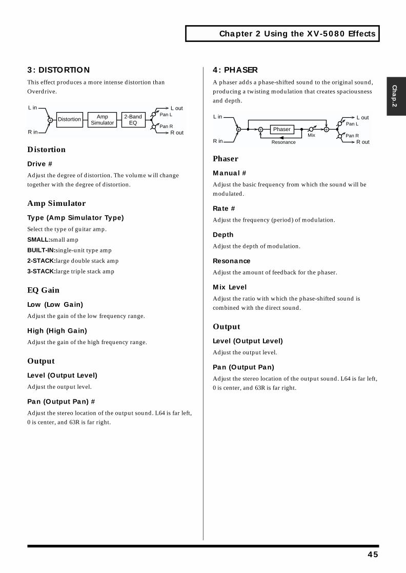
Chapter 2 Using the XV-5080 Effects
Chap.2
3: DISTORTIONThis effect produces a more intense distortion than Overdrive.fig.2-06
Distortion
Drive #
Adjust the degree of distortion. The volume will change together with the degree of distortion.
Amp Simulator
Type (Amp Simulator Type)
Select the type of guitar amp.
SMALL:small amp
BUILT-IN:single-unit type amp
2-STACK:large double stack amp
3-STACK:large triple stack amp
EQ Gain
Low (Low Gain)
Adjust the gain of the low frequency range.
High (High Gain)
Adjust the gain of the high frequency range.
Output
Level (Output Level)
Adjust the output level.
Pan (Output Pan) #
Adjust the stereo location of the output sound. L64 is far left, 0 is center, and 63R is far right.
4: PHASERA phaser adds a phase-shifted sound to the original sound, producing a twisting modulation that creates spaciousness and depth.fig.2-07
Phaser
Manual #
Adjust the basic frequency from which the sound will be modulated.
Rate #
Adjust the frequency (period) of modulation.
Depth
Adjust the depth of modulation.
Resonance
Adjust the amount of feedback for the phaser.
Mix Level
Adjust the ratio with which the phase-shifted sound is combined with the direct sound.
Output
Level (Output Level)
Adjust the output level.
Pan (Output Pan)
Adjust the stereo location of the output sound. L64 is far left, 0 is center, and 63R is far right.
L in
R in
L out
R outPan R
Pan LAmpSimulator
2-BandEQ
Distortion
Phaser
Resonance
Mix
L in
R in
L out
R outPan R
Pan L
45
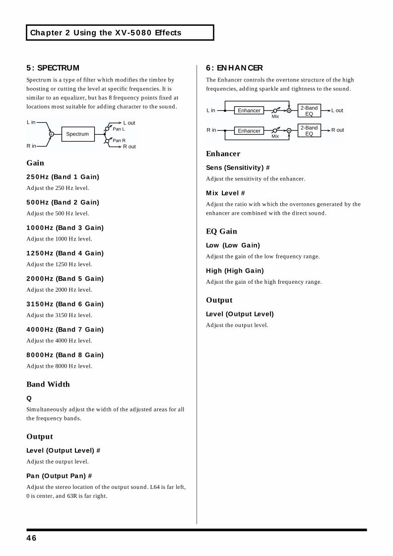
Chapter 2 Using the XV-5080 Effects
5: SPECTRUMSpectrum is a type of filter which modifies the timbre by boosting or cutting the level at specific frequencies. It is similar to an equalizer, but has 8 frequency points fixed at locations most suitable for adding character to the sound.fig.2-08
Gain
250Hz (Band 1 Gain)
Adjust the 250 Hz level.
500Hz (Band 2 Gain)
Adjust the 500 Hz level.
1000Hz (Band 3 Gain)
Adjust the 1000 Hz level.
1250Hz (Band 4 Gain)
Adjust the 1250 Hz level.
2000Hz (Band 5 Gain)
Adjust the 2000 Hz level.
3150Hz (Band 6 Gain)
Adjust the 3150 Hz level.
4000Hz (Band 7 Gain)
Adjust the 4000 Hz level.
8000Hz (Band 8 Gain)
Adjust the 8000 Hz level.
Band Width
Q
Simultaneously adjust the width of the adjusted areas for all the frequency bands.
Output
Level (Output Level) #
Adjust the output level.
Pan (Output Pan) #
Adjust the stereo location of the output sound. L64 is far left, 0 is center, and 63R is far right.
6: ENHANCERThe Enhancer controls the overtone structure of the high frequencies, adding sparkle and tightness to the sound.fig.2-09
Enhancer
Sens (Sensitivity) #
Adjust the sensitivity of the enhancer.
Mix Level #
Adjust the ratio with which the overtones generated by the enhancer are combined with the direct sound.
EQ Gain
Low (Low Gain)
Adjust the gain of the low frequency range.
High (High Gain)
Adjust the gain of the high frequency range.
Output
Level (Output Level)
Adjust the output level.
Spectrum
L out
R outPan R
Pan LL in
R in
L in
R in
L out
R outMix
MixEnhancer
Enhancer2-Band
EQ
2-BandEQ
46
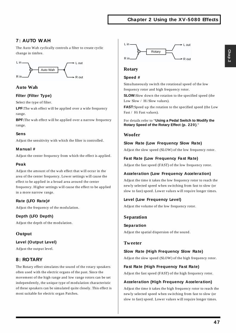
Chapter 2 Using the XV-5080 Effects
Chap.2
7: AUTO WAHThe Auto Wah cyclically controls a filter to create cyclic change in timbre.fig.2-10
Auto Wah
Filter (Filter Type)
Select the type of filter.
LPF:The wah effect will be applied over a wide frequency range.
BPF:The wah effect will be applied over a narrow frequency range.
Sens
Adjust the sensitivity with which the filter is controlled.
Manual #
Adjust the center frequency from which the effect is applied.
Peak
Adjust the amount of the wah effect that will occur in the area of the center frequency. Lower settings will cause the effect to be applied in a broad area around the center frequency. Higher settings will cause the effect to be applied in a more narrow range.
Rate (LFO Rate)#
Adjust the frequency of the modulation.
Depth (LFO Depth)
Adjust the depth of the modulation.
Output
Level (Output Level)
Adjust the output level.
8: ROTARYThe Rotary effect simulates the sound of the rotary speakers often used with the electric organs of the past. Since the movement of the high range and low range rotors can be set independently, the unique type of modulation characteristic of these speakers can be simulated quite closely. This effect is most suitable for electric organ Patches.
fig.2-11
Rotary
Speed #
Simultaneously switch the rotational speed of the low frequency rotor and high frequency rotor.
SLOW:Slow down the rotation to the specified speed (the Low Slow / Hi Slow values).
FAST:Speed up the rotation to the specified speed (the Low Fast / Hi Fast values).
For details refer to “Using a Pedal Switch to Modify the Rotary Speed of the Rotary Effect (p. 220).”
Woofer
Slow Rate (Low Frequency Slow Rate)
Adjust the slow speed (SLOW) of the low frequency rotor.
Fast Rate (Low Frequency Fast Rate)
Adjust the fast speed (FAST) of the low frequency rotor.
Acceleration (Low Frequency Acceleration)
Adjust the time it takes the low frequency rotor to reach the newly selected speed when switching from fast to slow (or slow to fast) speed. Lower values will require longer times.
Level (Low Frequency Level)
Adjust the volume of the low frequency rotor.
Separation
Separation
Adjust the spatial dispersion of the sound.
Tweeter
Slow Rate (High Frequency Slow Rate)
Adjust the slow speed (SLOW) of the high frequency rotor.
Fast Rate (High Frequency Fast Rate)
Adjust the fast speed (FAST) of the high frequency rotor.
Acceleration (High Frequency Acceleration)
Adjust the time it takes the high frequency rotor to reach the newly selected speed when switching from fast to slow (or slow to fast) speed. Lower values will require longer times.
Auto Wah
L out
R out
L in
R in
L out
R out
L in
R in
Rotary
47
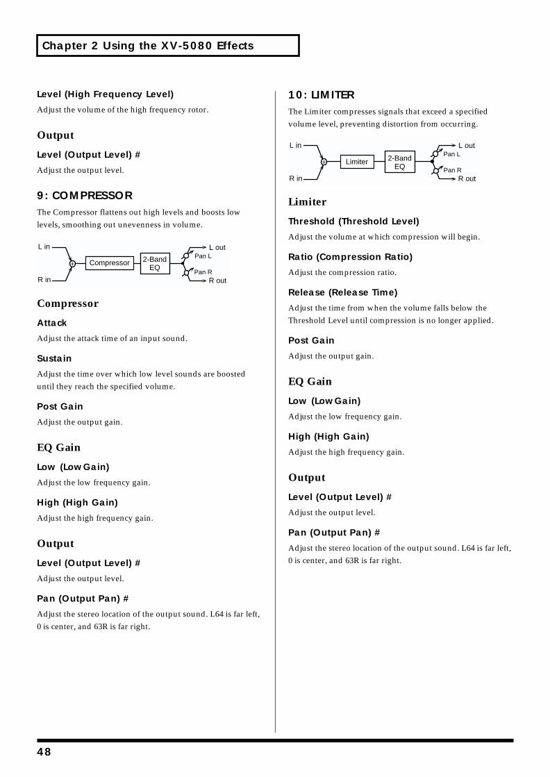
Chapter 2 Using the XV-5080 Effects
Level (High Frequency Level)
Adjust the volume of the high frequency rotor.
Output
Level (Output Level) #
Adjust the output level.
9: COMPRESSORThe Compressor flattens out high levels and boosts low levels, smoothing out unevenness in volume.fig.2-12
Compressor
Attack
Adjust the attack time of an input sound.
Sustain
Adjust the time over which low level sounds are boosted until they reach the specified volume.
Post Gain
Adjust the output gain.
EQ Gain
Low (LowGain)
Adjust the low frequency gain.
High (High Gain)
Adjust the high frequency gain.
Output
Level (Output Level) #
Adjust the output level.
Pan (Output Pan) #
Adjust the stereo location of the output sound. L64 is far left, 0 is center, and 63R is far right.
10: LIMITERThe Limiter compresses signals that exceed a specified volume level, preventing distortion from occurring.fig.2-13
Limiter
Threshold (Threshold Level)
Adjust the volume at which compression will begin.
Ratio (Compression Ratio)
Adjust the compression ratio.
Release (Release Time)
Adjust the time from when the volume falls below the Threshold Level until compression is no longer applied.
Post Gain
Adjust the output gain.
EQ Gain
Low (LowGain)
Adjust the low frequency gain.
High (High Gain)
Adjust the high frequency gain.
Output
Level (Output Level) #
Adjust the output level.
Pan (Output Pan) #
Adjust the stereo location of the output sound. L64 is far left, 0 is center, and 63R is far right.
L in
R in
L out
R outPan R
Pan LCompressor 2-Band
EQ
L in
R in
L out
R outPan R
Pan LLimiter 2-Band
EQ
48
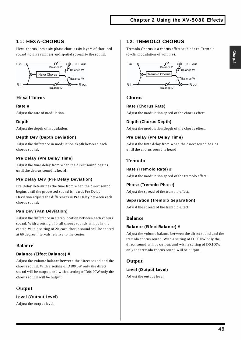
Chapter 2 Using the XV-5080 Effects
Chap.2
11: HEXA-CHORUSHexa-chorus uses a six-phase chorus (six layers of chorused sound) to give richness and spatial spread to the sound.fig.2-14
Hexa Chorus
Rate #
Adjust the rate of modulation.
Depth
Adjust the depth of modulation.
Depth Dev (Depth Deviation)
Adjust the difference in modulation depth between each chorus sound.
Pre Delay (Pre Delay Time)
Adjust the time delay from when the direct sound begins until the chorus sound is heard.
Pre Delay Dev (Pre Delay Deviation)
Pre Delay determines the time from when the direct sound begins until the processed sound is heard. Pre Delay Deviation adjusts the differences in Pre Delay between each chorus sound.
Pan Dev (Pan Deviation)
Adjust the difference in stereo location between each chorus sound. With a setting of 0, all chorus sounds will be in the center. With a setting of 20, each chorus sound will be spaced at 60 degree intervals relative to the center.
Balance
Balance (Effect Balance) #
Adjust the volume balance between the direct sound and the chorus sound. With a setting of D100:0W only the direct sound will be output, and with a setting of D0:100W only the chorus sound will be output.
Output
Level (Output Level)
Adjust the output level.
12: TREMOLO CHORUSTremolo Chorus is a chorus effect with added Tremolo (cyclic modulation of volume).fig.2-15
Chorus
Rate (Chorus Rate)
Adjust the modulation speed of the chorus effect.
Depth (Chorus Depth)
Adjust the modulation depth of the chorus effect.
Pre Delay (Pre Delay Time)
Adjust the time delay from when the direct sound begins until the chorus sound is heard.
Tremolo
Rate (Tremolo Rate) #
Adjust the modulation speed of the tremolo effect.
Phase (Tremolo Phase)
Adjust the spread of the tremolo effect.
Separation (Tremolo Separation)
Adjust the spread of the tremolo effect.
Balance
Balance (Effect Balance) #
Adjust the volume balance between the direct sound and the tremolo chorus sound. With a setting of D100:0W only the direct sound will be output, and with a setting of D0:100W only the tremolo chorus sound will be output.
Output
Level (Output Level)
Adjust the output level.
Balance W
Balance W
L in
R in
L out
R out
Hexa Chorus
Balance D
Balance D
Tremolo Chorus
L in
R in
L out
R outBalance D
Balance D
Balance W
Balance W
49
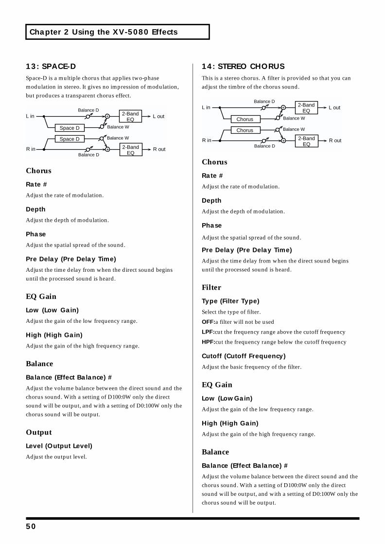
Chapter 2 Using the XV-5080 Effects
13: SPACE-DSpace-D is a multiple chorus that applies two-phase modulation in stereo. It gives no impression of modulation, but produces a transparent chorus effect.fig.2-16
Chorus
Rate #
Adjust the rate of modulation.
Depth
Adjust the depth of modulation.
Phase
Adjust the spatial spread of the sound.
Pre Delay (Pre Delay Time)
Adjust the time delay from when the direct sound begins until the processed sound is heard.
EQ Gain
Low (Low Gain)
Adjust the gain of the low frequency range.
High (High Gain)
Adjust the gain of the high frequency range.
Balance
Balance (Effect Balance) #
Adjust the volume balance between the direct sound and the chorus sound. With a setting of D100:0W only the direct sound will be output, and with a setting of D0:100W only the chorus sound will be output.
Output
Level (Output Level)
Adjust the output level.
14: STEREO CHORUSThis is a stereo chorus. A filter is provided so that you can adjust the timbre of the chorus sound.fig.2-17
Chorus
Rate #
Adjust the rate of modulation.
Depth
Adjust the depth of modulation.
Phase
Adjust the spatial spread of the sound.
Pre Delay (Pre Delay Time)
Adjust the time delay from when the direct sound begins until the processed sound is heard.
Filter
Type (Filter Type)
Select the type of filter.
OFF:a filter will not be used
LPF:cut the frequency range above the cutoff frequency
HPF:cut the frequency range below the cutoff frequency
Cutoff (Cutoff Frequency)
Adjust the basic frequency of the filter.
EQ Gain
Low (LowGain)
Adjust the gain of the low frequency range.
High (High Gain)
Adjust the gain of the high frequency range.
Balance
Balance (Effect Balance) #
Adjust the volume balance between the direct sound and the chorus sound. With a setting of D100:0W only the direct sound will be output, and with a setting of D0:100W only the chorus sound will be output.
L in
R in
Space D
Space D
L out
R out
2-BandEQ
2-BandEQ
Balance W
Balance W
Balance D
Balance D L in
R in
Chorus
Chorus
L out
R out
2-BandEQ
2-BandEQ
Balance W
Balance W
Balance D
Balance D
50
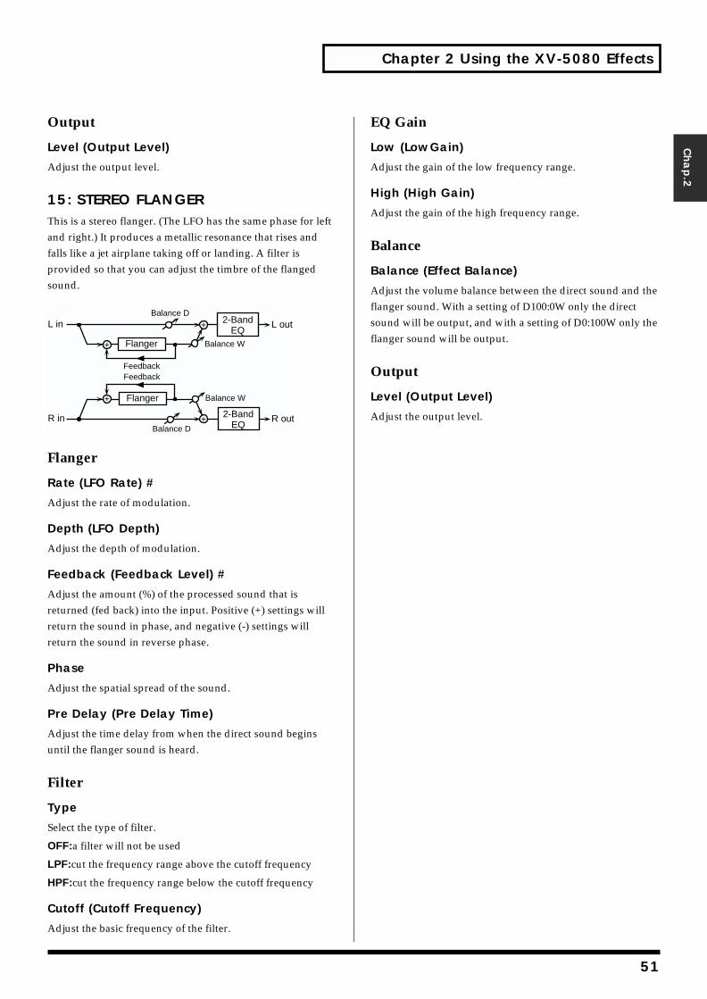
Chapter 2 Using the XV-5080 Effects
Chap.2
Output
Level (Output Level)
Adjust the output level.
15: STEREO FLANGERThis is a stereo flanger. (The LFO has the same phase for left and right.) It produces a metallic resonance that rises and falls like a jet airplane taking off or landing. A filter is provided so that you can adjust the timbre of the flanged sound.fig.2-18
Flanger
Rate (LFO Rate) #
Adjust the rate of modulation.
Depth (LFO Depth)
Adjust the depth of modulation.
Feedback (Feedback Level) #
Adjust the amount (%) of the processed sound that is returned (fed back) into the input. Positive (+) settings will return the sound in phase, and negative (-) settings will return the sound in reverse phase.
Phase
Adjust the spatial spread of the sound.
Pre Delay (Pre Delay Time)
Adjust the time delay from when the direct sound begins until the flanger sound is heard.
Filter
Type
Select the type of filter.
OFF:a filter will not be used
LPF:cut the frequency range above the cutoff frequency
HPF:cut the frequency range below the cutoff frequency
Cutoff (Cutoff Frequency)
Adjust the basic frequency of the filter.
EQ Gain
Low (LowGain)
Adjust the gain of the low frequency range.
High (High Gain)
Adjust the gain of the high frequency range.
Balance
Balance (Effect Balance)
Adjust the volume balance between the direct sound and the flanger sound. With a setting of D100:0W only the direct sound will be output, and with a setting of D0:100W only the flanger sound will be output.
Output
Level (Output Level)
Adjust the output level.R in R out
L in L out
Flanger
FeedbackFeedback
Flanger
Balance W
Balance D
Balance W
Balance D
2-BandEQ
2-BandEQ
51
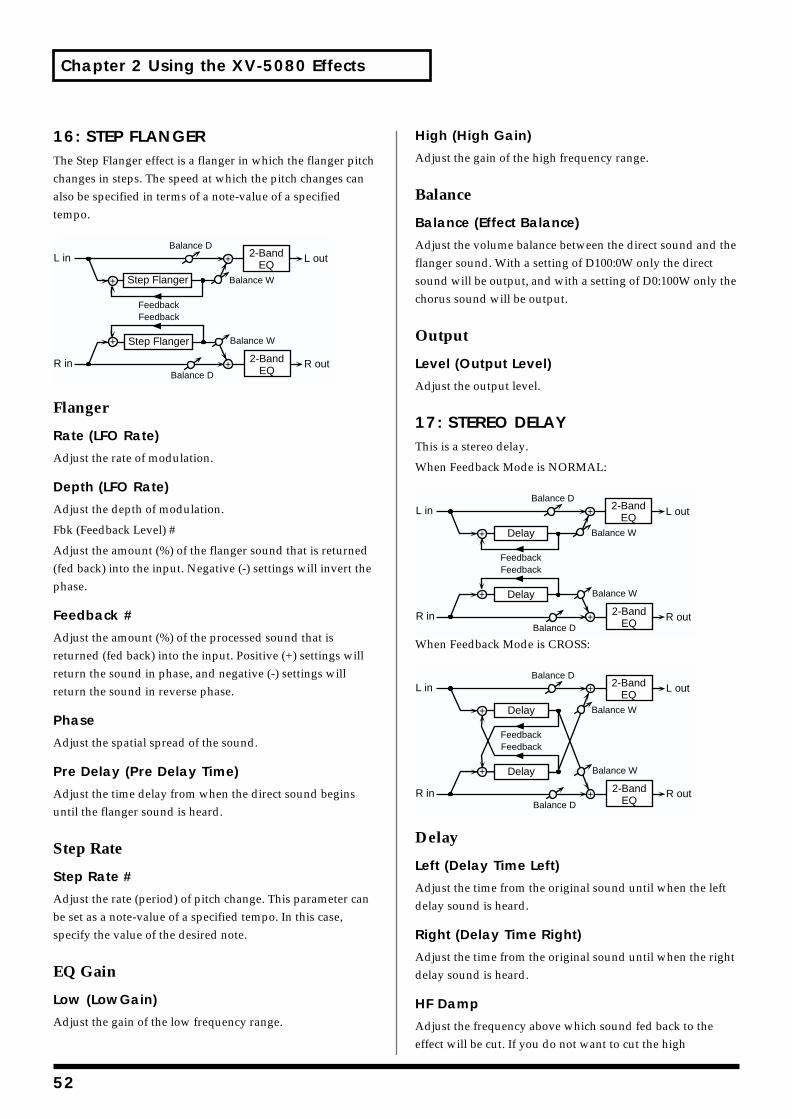
Chapter 2 Using the XV-5080 Effects
16: STEP FLANGERThe Step Flanger effect is a flanger in which the flanger pitch changes in steps. The speed at which the pitch changes can also be specified in terms of a note-value of a specified tempo.fig.2-19
Flanger
Rate (LFO Rate)
Adjust the rate of modulation.
Depth (LFO Rate)
Adjust the depth of modulation.
Fbk (Feedback Level) #
Adjust the amount (%) of the flanger sound that is returned (fed back) into the input. Negative (-) settings will invert the phase.
Feedback #
Adjust the amount (%) of the processed sound that is returned (fed back) into the input. Positive (+) settings will return the sound in phase, and negative (-) settings will return the sound in reverse phase.
Phase
Adjust the spatial spread of the sound.
Pre Delay (Pre Delay Time)
Adjust the time delay from when the direct sound begins until the flanger sound is heard.
Step Rate
Step Rate #
Adjust the rate (period) of pitch change. This parameter can be set as a note-value of a specified tempo. In this case, specify the value of the desired note.
EQ Gain
Low (LowGain)
Adjust the gain of the low frequency range.
High (High Gain)
Adjust the gain of the high frequency range.
Balance
Balance (Effect Balance)
Adjust the volume balance between the direct sound and the flanger sound. With a setting of D100:0W only the direct sound will be output, and with a setting of D0:100W only the chorus sound will be output.
Output
Level (Output Level)
Adjust the output level.
17: STEREO DELAYThis is a stereo delay.
When Feedback Mode is NORMAL:fig.2-20
When Feedback Mode is CROSS:fig.2-21
Delay
Left (Delay Time Left)
Adjust the time from the original sound until when the left delay sound is heard.
Right (Delay Time Right)
Adjust the time from the original sound until when the right delay sound is heard.
HF Damp
Adjust the frequency above which sound fed back to the effect will be cut. If you do not want to cut the high
R in R out
L in L out
FeedbackFeedback
Balance W
Balance D
Balance W
Balance D
2-BandEQ
2-BandEQ
Step Flanger
Step Flanger
R in R out
L in L out
FeedbackFeedback
Balance W
Balance D
Balance W
Balance D
2-BandEQ
2-BandEQ
Delay
Delay
R in R out
L in L out
FeedbackFeedback
Balance W
Balance D
Balance W
Balance D
2-BandEQ
2-BandEQ
Delay
Delay
52
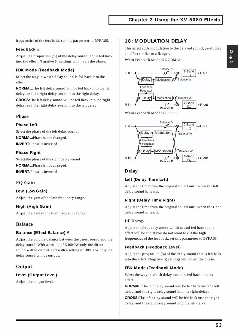
Chapter 2 Using the XV-5080 Effects
Chap.2
frequencies of the feedback, set this parameter to BYPASS.
Feedback #
Adjust the proportion (%) of the delay sound that is fed back into the effect. Negative (-) settings will invert the phase.
FBK Mode (Feedback Mode)
Select the way in which delay sound is fed back into the effect.
NORMAL:The left delay sound will be fed back into the left delay, and the right delay sound into the right delay.
CROSS:The left delay sound will be fed back into the right delay, and the right delay sound into the left delay.
Phase
Phase Left
Select the phase of the left delay sound.
NORMAL:Phase is not changed.
INVERT:Phase is inverted.
Phase Right
Select the phase of the right delay sound.
NORMAL:Phase is not changed.
INVERT:Phase is inverted.
EQ Gain
Low (LowGain)
Adjust the gain of the low frequency range.
High (High Gain)
Adjust the gain of the high frequency range.
Balance
Balance (Effect Balance) #
Adjust the volume balance between the direct sound and the delay sound. With a setting of D100:0W only the direct sound will be output, and with a setting of D0:100W only the delay sound will be output.
Output
Level (Output Level)
Adjust the output level.
18: MODULATION DELAYThis effect adds modulation to the delayed sound, producing an effect similar to a flanger.
When Feedback Mode is NORMAL:fig.2-22
When Feedback Mode is CROSS:fig.2-23
Delay
Left (Delay Time Left)
Adjust the time from the original sound until when the left delay sound is heard.
Right (Delay Time Right)
Adjust the time from the original sound until when the right delay sound is heard.
HF Damp
Adjust the frequency above which sound fed back to the effect will be cut. If you do not want to cut the high frequencies of the feedback, set this parameter to BYPASS.
Feedback (Feedback Level)
Adjust the proportion (%) of the delay sound that is fed back into the effect. Negative (-) settings will invert the phase.
FBK Mode (Feedback Mode)
Select the way in which delay sound is fed back into the effect.
NORMAL:The left delay sound will be fed back into the left delay, and the right delay sound into the right delay.
CROSS:The left delay sound will be fed back into the right delay, and the right delay sound into the left delay.
R in R out
L in L out
FeedbackFeedback
Balance W
Balance D
Balance W
Balance D
2-BandEQ
2-BandEQ
Delay
Delay
Modulation
Modulation
R in R out
L in L out
FeedbackFeedback
Balance W
Balance D
Balance W
Balance D
2-BandEQ
2-BandEQ
Delay
Delay
Modulation
Modulation
53
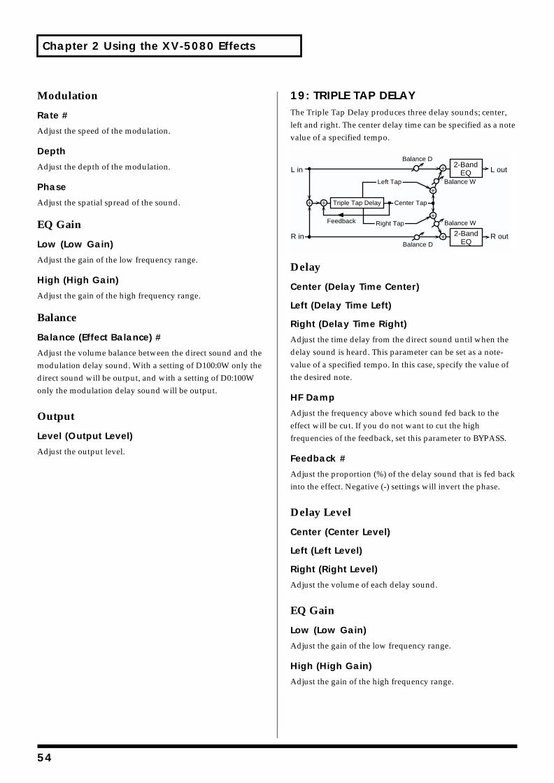
Chapter 2 Using the XV-5080 Effects
Modulation
Rate #
Adjust the speed of the modulation.
Depth
Adjust the depth of the modulation.
Phase
Adjust the spatial spread of the sound.
EQ Gain
Low (Low Gain)
Adjust the gain of the low frequency range.
High (High Gain)
Adjust the gain of the high frequency range.
Balance
Balance (Effect Balance) #
Adjust the volume balance between the direct sound and the modulation delay sound. With a setting of D100:0W only the direct sound will be output, and with a setting of D0:100W only the modulation delay sound will be output.
Output
Level (Output Level)
Adjust the output level.
19: TRIPLE TAP DELAYThe Triple Tap Delay produces three delay sounds; center, left and right. The center delay time can be specified as a note value of a specified tempo.fig.2-24
Delay
Center (Delay Time Center)
Left (Delay Time Left)
Right (Delay Time Right)
Adjust the time delay from the direct sound until when the delay sound is heard. This parameter can be set as a note-value of a specified tempo. In this case, specify the value of the desired note.
HF Damp
Adjust the frequency above which sound fed back to the effect will be cut. If you do not want to cut the high frequencies of the feedback, set this parameter to BYPASS.
Feedback #
Adjust the proportion (%) of the delay sound that is fed back into the effect. Negative (-) settings will invert the phase.
Delay Level
Center (Center Level)
Left (Left Level)
Right (Right Level)
Adjust the volume of each delay sound.
EQ Gain
Low (Low Gain)
Adjust the gain of the low frequency range.
High (High Gain)
Adjust the gain of the high frequency range.
L in
R in
L out
R out
Left Tap
Right Tap
Triple Tap Delay
2-BandEQ
2-BandEQ
Balance W
Balance D
Balance W
Balance D
Feedback
Center Tap
54
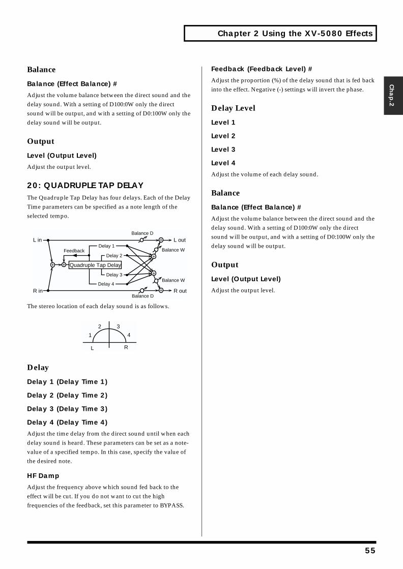
Chapter 2 Using the XV-5080 Effects
Chap.2
Balance
Balance (Effect Balance) #
Adjust the volume balance between the direct sound and the delay sound. With a setting of D100:0W only the direct sound will be output, and with a setting of D0:100W only the delay sound will be output.
Output
Level (Output Level)
Adjust the output level.
20: QUADRUPLE TAP DELAYThe Quadruple Tap Delay has four delays. Each of the Delay Time parameters can be specified as a note length of the selected tempo.fig.2-25
The stereo location of each delay sound is as follows.fig.2-26
Delay
Delay 1 (Delay Time 1)
Delay 2 (Delay Time 2)
Delay 3 (Delay Time 3)
Delay 4 (Delay Time 4)
Adjust the time delay from the direct sound until when each delay sound is heard. These parameters can be set as a note-value of a specified tempo. In this case, specify the value of the desired note.
HF Damp
Adjust the frequency above which sound fed back to the effect will be cut. If you do not want to cut the high frequencies of the feedback, set this parameter to BYPASS.
Feedback (Feedback Level) #
Adjust the proportion (%) of the delay sound that is fed back into the effect. Negative (-) settings will invert the phase.
Delay Level
Level 1
Level 2
Level 3
Level 4
Adjust the volume of each delay sound.
Balance
Balance (Effect Balance) #
Adjust the volume balance between the direct sound and the delay sound. With a setting of D100:0W only the direct sound will be output, and with a setting of D0:100W only the delay sound will be output.
Output
Level (Output Level)
Adjust the output level.
L in
R in
L out
R out
Quadruple Tap Delay
Balance W
Balance D
Balance W
Balance D
Delay 1
Delay 2
Delay 3
Delay 4
Feedback
1
2 3
4
L R
55
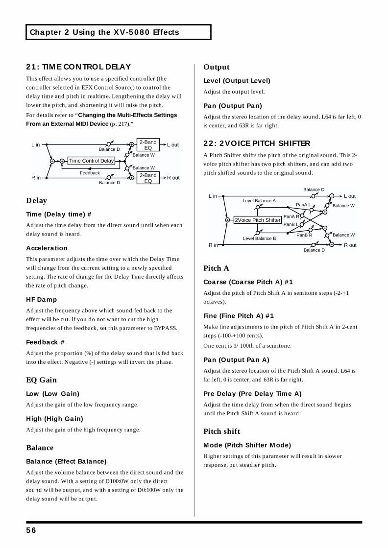
Chapter 2 Using the XV-5080 Effects
21: TIME CONTROL DELAYThis effect allows you to use a specified controller (the controller selected in EFX Control Source) to control the delay time and pitch in realtime. Lengthening the delay will lower the pitch, and shortening it will raise the pitch.
For details refer to “Changing the Multi-Effects Settings
From an External MIDI Device (p. 217).”fig.2-27
Delay
Time (Delay time) #
Adjust the time delay from the direct sound until when each delay sound is heard.
Acceleration
This parameter adjusts the time over which the Delay Time will change from the current setting to a newly specified setting. The rate of change for the Delay Time directly affects the rate of pitch change.
HF Damp
Adjust the frequency above which sound fed back to the effect will be cut. If you do not want to cut the high frequencies of the feedback, set this parameter to BYPASS.
Feedback #
Adjust the proportion (%) of the delay sound that is fed back into the effect. Negative (-) settings will invert the phase.
EQ Gain
Low (Low Gain)
Adjust the gain of the low frequency range.
High (High Gain)
Adjust the gain of the high frequency range.
Balance
Balance (Effect Balance)
Adjust the volume balance between the direct sound and the delay sound. With a setting of D100:0W only the direct sound will be output, and with a setting of D0:100W only the delay sound will be output.
Output
Level (Output Level)
Adjust the output level.
Pan (Output Pan)
Adjust the stereo location of the delay sound. L64 is far left, 0 is center, and 63R is far right.
22: 2VOICE PITCH SHIFTERA Pitch Shifter shifts the pitch of the original sound. This 2-voice pitch shifter has two pitch shifters, and can add two pitch shifted sounds to the original sound.fig.2-28
Pitch A
Coarse (Coarse Pitch A) #1
Adjust the pitch of Pitch Shift A in semitone steps (-2-+1 octaves).
Fine (Fine Pitch A) #1
Make fine adjustments to the pitch of Pitch Shift A in 2-cent steps (-100-+100 cents).
One cent is 1/100th of a semitone.
Pan (Output Pan A)
Adjust the stereo location of the Pitch Shift A sound. L64 is far left, 0 is center, and 63R is far right.
Pre Delay (Pre Delay Time A)
Adjust the time delay from when the direct sound begins until the Pitch Shift A sound is heard.
Pitch shift
Mode (Pitch Shifter Mode)
Higher settings of this parameter will result in slower response, but steadier pitch.
L in
R in
L out
R out2-BandEQ
Balance W
Balance W
Balance D
Balance D
2-BandEQ
Feedback
Time Control Delay
L in
R in
L out
R out
2Voice Pitch Shifter
Level Balance ABalance W
Balance D
Balance W
Balance D
Level Balance BPanB R
PanA L
PanA R
PanB L
56
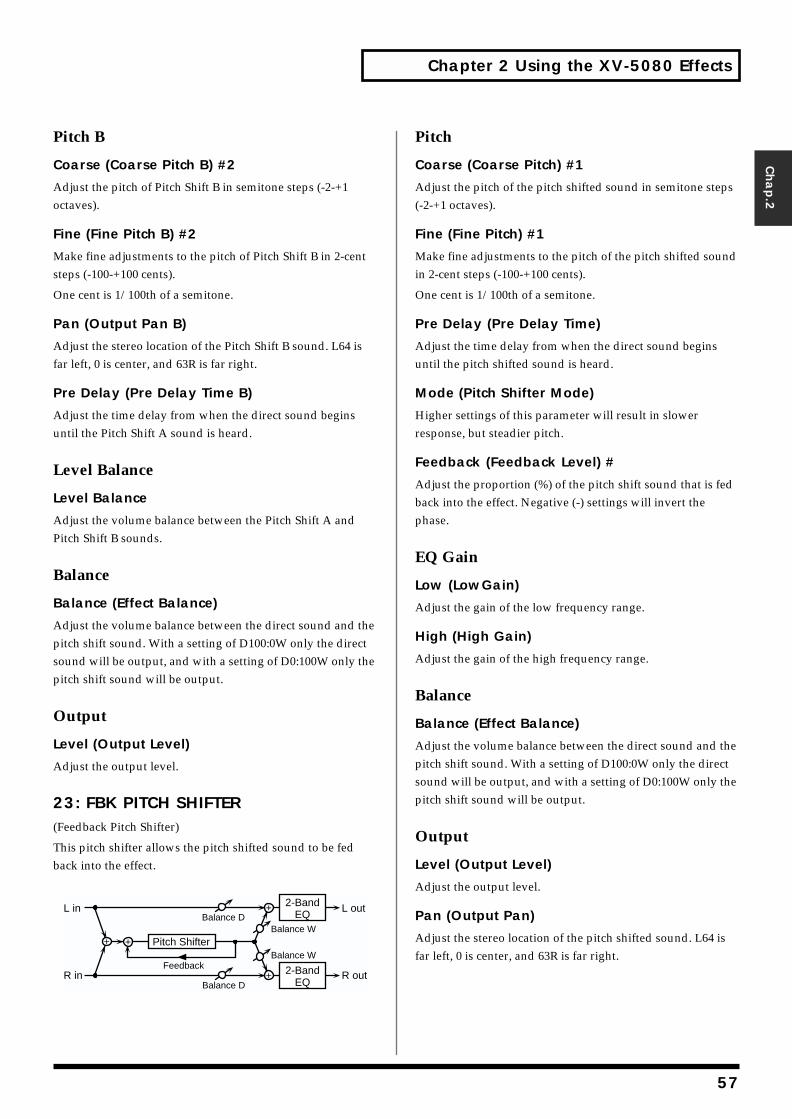
Chapter 2 Using the XV-5080 Effects
Chap.2
Pitch B
Coarse (Coarse Pitch B) #2
Adjust the pitch of Pitch Shift B in semitone steps (-2-+1 octaves).
Fine (Fine Pitch B) #2
Make fine adjustments to the pitch of Pitch Shift B in 2-cent steps (-100-+100 cents).
One cent is 1/100th of a semitone.
Pan (Output Pan B)
Adjust the stereo location of the Pitch Shift B sound. L64 is far left, 0 is center, and 63R is far right.
Pre Delay (Pre Delay Time B)
Adjust the time delay from when the direct sound begins until the Pitch Shift A sound is heard.
Level Balance
Level Balance
Adjust the volume balance between the Pitch Shift A and Pitch Shift B sounds.
Balance
Balance (Effect Balance)
Adjust the volume balance between the direct sound and the pitch shift sound. With a setting of D100:0W only the direct sound will be output, and with a setting of D0:100W only the pitch shift sound will be output.
Output
Level (Output Level)
Adjust the output level.
23: FBK PITCH SHIFTER (Feedback Pitch Shifter)
This pitch shifter allows the pitch shifted sound to be fed back into the effect.fig.2-29
Pitch
Coarse (Coarse Pitch) #1
Adjust the pitch of the pitch shifted sound in semitone steps (-2-+1 octaves).
Fine (Fine Pitch) #1
Make fine adjustments to the pitch of the pitch shifted sound in 2-cent steps (-100-+100 cents).
One cent is 1/100th of a semitone.
Pre Delay (Pre Delay Time)
Adjust the time delay from when the direct sound begins until the pitch shifted sound is heard.
Mode (Pitch Shifter Mode)
Higher settings of this parameter will result in slower response, but steadier pitch.
Feedback (Feedback Level) #
Adjust the proportion (%) of the pitch shift sound that is fed back into the effect. Negative (-) settings will invert the phase.
EQ Gain
Low (LowGain)
Adjust the gain of the low frequency range.
High (High Gain)
Adjust the gain of the high frequency range.
Balance
Balance (Effect Balance)
Adjust the volume balance between the direct sound and the pitch shift sound. With a setting of D100:0W only the direct sound will be output, and with a setting of D0:100W only the pitch shift sound will be output.
Output
Level (Output Level)
Adjust the output level.
Pan (Output Pan)
Adjust the stereo location of the pitch shifted sound. L64 is far left, 0 is center, and 63R is far right.
L in
R in
L out
R out2-BandEQ
Balance W
Balance W
Balance D
Balance D
2-BandEQ
Feedback
Pitch Shifter
57
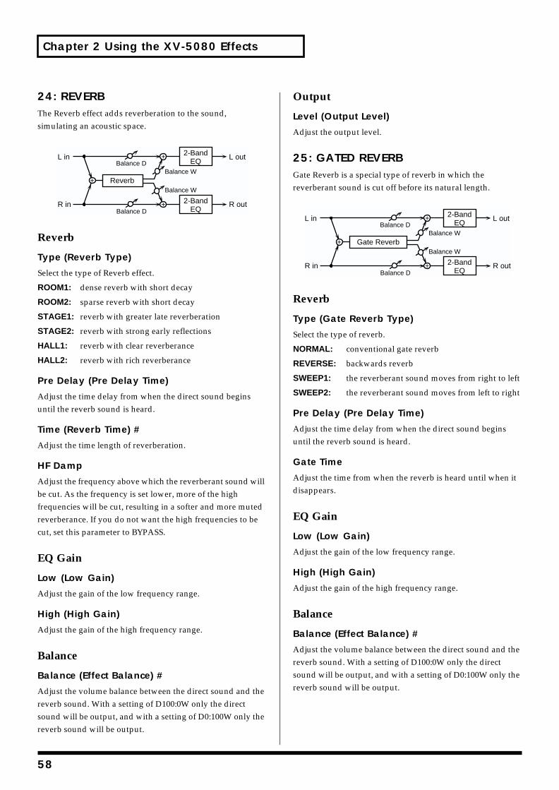
Chapter 2 Using the XV-5080 Effects
24: REVERBThe Reverb effect adds reverberation to the sound, simulating an acoustic space.fig.2-30
Reverb
Type (Reverb Type)
Select the type of Reverb effect.
ROOM1: dense reverb with short decay
ROOM2: sparse reverb with short decay
STAGE1: reverb with greater late reverberation
STAGE2: reverb with strong early reflections
HALL1: reverb with clear reverberance
HALL2: reverb with rich reverberance
Pre Delay (Pre Delay Time)
Adjust the time delay from when the direct sound begins until the reverb sound is heard.
Time (Reverb Time) #
Adjust the time length of reverberation.
HF Damp
Adjust the frequency above which the reverberant sound will be cut. As the frequency is set lower, more of the high frequencies will be cut, resulting in a softer and more muted reverberance. If you do not want the high frequencies to be cut, set this parameter to BYPASS.
EQ Gain
Low (Low Gain)
Adjust the gain of the low frequency range.
High (High Gain)
Adjust the gain of the high frequency range.
Balance
Balance (Effect Balance) #
Adjust the volume balance between the direct sound and the reverb sound. With a setting of D100:0W only the direct sound will be output, and with a setting of D0:100W only the reverb sound will be output.
Output
Level (Output Level)
Adjust the output level.
25: GATED REVERBGate Reverb is a special type of reverb in which the reverberant sound is cut off before its natural length.fig.2-31
Reverb
Type (Gate Reverb Type)
Select the type of reverb.
NORMAL: conventional gate reverb
REVERSE: backwards reverb
SWEEP1: the reverberant sound moves from right to left
SWEEP2: the reverberant sound moves from left to right
Pre Delay (Pre Delay Time)
Adjust the time delay from when the direct sound begins until the reverb sound is heard.
Gate Time
Adjust the time from when the reverb is heard until when it disappears.
EQ Gain
Low (Low Gain)
Adjust the gain of the low frequency range.
High (High Gain)
Adjust the gain of the high frequency range.
Balance
Balance (Effect Balance) #
Adjust the volume balance between the direct sound and the reverb sound. With a setting of D100:0W only the direct sound will be output, and with a setting of D0:100W only the reverb sound will be output.
L in
R in
L out
R out
Reverb
2-BandEQ
Balance W
Balance W
Balance D
Balance D
2-BandEQ
L in
R in
L out
R out
Gate Reverb
2-BandEQ
Balance W
Balance W
Balance D
Balance D
2-BandEQ
58

Chapter 2 Using the XV-5080 Effects
Chap.2
Output
Level (Output Level) #
Adjust the output level.
26: OVERDRIVE→CHORUSThis effect connects an overdrive and a chorus in series.fig.2-32
Overdrive
Drive
Adjust the degree of overdrive distortion. The volume will change together with the degree of distortion.
Pan (Overdrive Pan) #
Adjust the stereo location of the overdrive sound. L64 is far left, 0 is center, and 63R is far right.
Chorus
Pre Delay (Chorus Pre Delay Time)
Adjust the time delay from when the direct sound begins until the chorus sound is heard.
Rate (Chorus Rate)
Adjust the modulation speed of the chorus effect.
Depth (Depth Rate)
Adjust the modulation depth of the chorus effect.
Balance (Chorus Balance) #
Adjust the volume balance between the overdrive sound that is sent through the chorus and the overdrive sound that is not sent through the chorus. With a setting of “D100: 0W,” only the overdrive sound will be output. With a setting of “D0: 100W,” only the overdrive sound that is sent through the chorus will be output.
Output
Level (Output Level)
Adjust the output level.
27: OVERDRIVE→FLANGERThis effect connects an overdrive and a flanger in series.fig.2-33
Overdrive
Drive
Adjust the degree of overdrive distortion. The volume will change together with the degree of distortion.
Pan (Overdrive Pan) #
Adjust the stereo location of the overdrive sound. L64 is far left, 0 is center, and 63R is far right.
Flanger
Pre Delay (Flanger Pre Delay Time)
Adjust the time delay from when the direct sound begins until the flanger sound is heard.
Rate (Flanger Rate)
Adjust the modulation speed of the flanger effect.
Depth (Flanger Depth)
Adjust the modulation depth of the flanger effect.
Feedback (Flanger Feedback)
Adjust the proportion (%) of the flanger sound that is fed back into the effect. Negative (-) settings will invert the phase.
Balance (Flanger Balance) #
Adjust the volume balance between the overdrive sound that is sent through the flanger and the overdrive sound that is not sent through the flanger. With a setting of “D100: 0W,” only the overdrive sound will be output. With a setting of “D0: 100W,” only the overdrive sound that is sent through the flanger will be output.
Output
Level (Output Level)
Adjust the output level.
L in
R in
ChorusOverdrive
L out
R out
Balance W
Balance W
Balance D
Balance D
L in
R in
FlangerOverdrive
L out
R out
Balance W
Balance W
Balance D
Balance D
Feedback
59
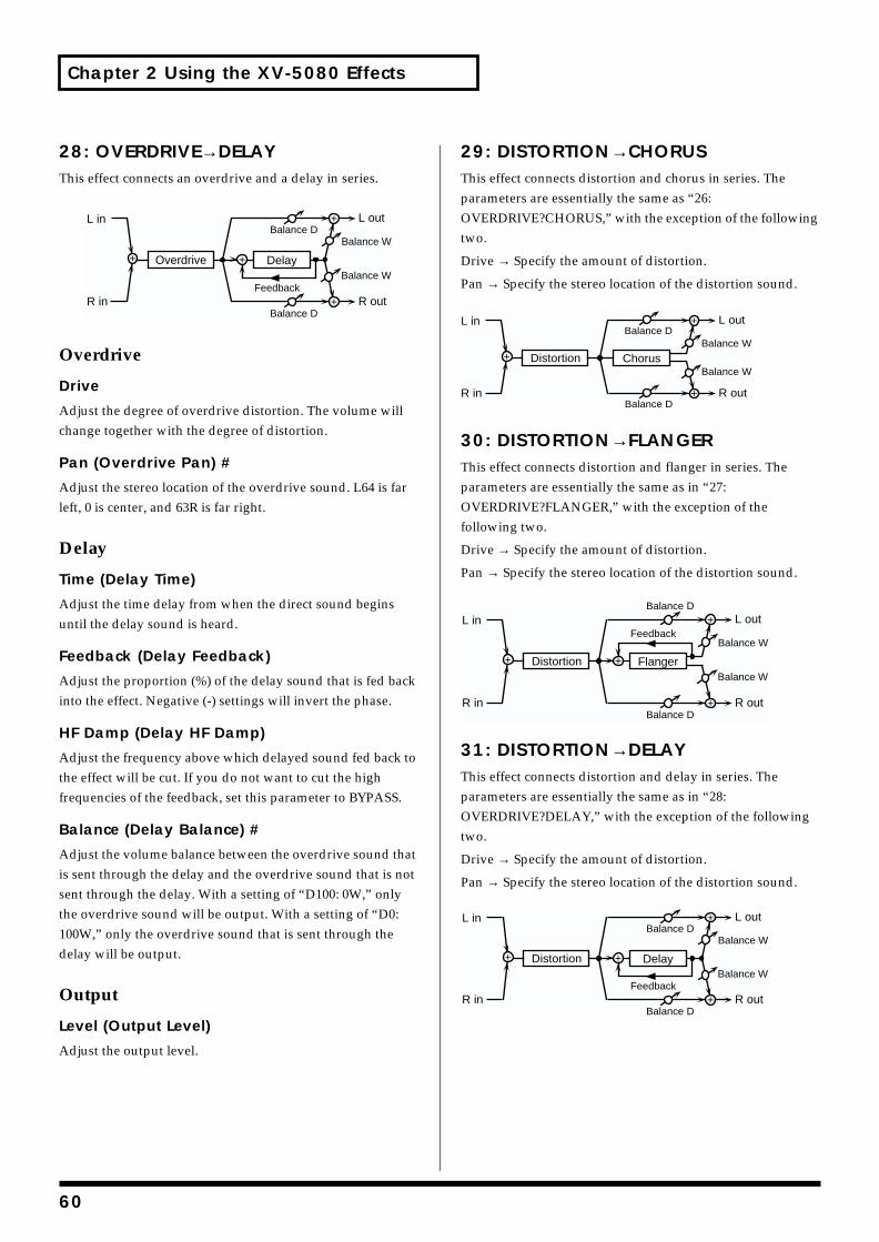
Chapter 2 Using the XV-5080 Effects
28: OVERDRIVE→DELAYThis effect connects an overdrive and a delay in series.fig.2-34
Overdrive
Drive
Adjust the degree of overdrive distortion. The volume will change together with the degree of distortion.
Pan (Overdrive Pan) #
Adjust the stereo location of the overdrive sound. L64 is far left, 0 is center, and 63R is far right.
Delay
Time (Delay Time)
Adjust the time delay from when the direct sound begins until the delay sound is heard.
Feedback (Delay Feedback)
Adjust the proportion (%) of the delay sound that is fed back into the effect. Negative (-) settings will invert the phase.
HF Damp (Delay HF Damp)
Adjust the frequency above which delayed sound fed back to the effect will be cut. If you do not want to cut the high frequencies of the feedback, set this parameter to BYPASS.
Balance (Delay Balance) #
Adjust the volume balance between the overdrive sound that is sent through the delay and the overdrive sound that is not sent through the delay. With a setting of “D100: 0W,” only the overdrive sound will be output. With a setting of “D0: 100W,” only the overdrive sound that is sent through the delay will be output.
Output
Level (Output Level)
Adjust the output level.
29: DISTORTION→CHORUSThis effect connects distortion and chorus in series. The parameters are essentially the same as “26: OVERDRIVE?CHORUS,” with the exception of the following two.
Drive → Specify the amount of distortion.
Pan → Specify the stereo location of the distortion sound.fig.2-35
30: DISTORTION→FLANGERThis effect connects distortion and flanger in series. The parameters are essentially the same as in “27: OVERDRIVE?FLANGER,” with the exception of the following two.
Drive → Specify the amount of distortion.
Pan → Specify the stereo location of the distortion sound.fig.2-36
31: DISTORTION→DELAYThis effect connects distortion and delay in series. The parameters are essentially the same as in “28: OVERDRIVE?DELAY,” with the exception of the following two.
Drive → Specify the amount of distortion.
Pan → Specify the stereo location of the distortion sound.fig.2-37
L in
R in
DelayOverdrive
L out
R out
Balance W
Balance W
Balance D
Balance D
Feedback
L in
R in
ChorusDistortion
L out
R out
Balance W
Balance W
Balance D
Balance D
L in
R in
FlangerDistortion
L out
R out
Balance W
Balance W
Balance D
Balance D
Feedback
L in
R in
DelayDistortion
L out
R out
Balance W
Balance W
Balance D
Balance D
Feedback
60
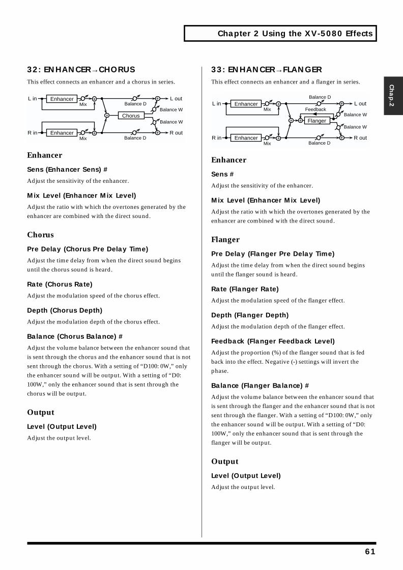
Chapter 2 Using the XV-5080 Effects
Chap.2
32: ENHANCER→CHORUSThis effect connects an enhancer and a chorus in series.fig.2-38
Enhancer
Sens (Enhancer Sens) #
Adjust the sensitivity of the enhancer.
Mix Level (Enhancer Mix Level)
Adjust the ratio with which the overtones generated by the enhancer are combined with the direct sound.
Chorus
Pre Delay (Chorus Pre Delay Time)
Adjust the time delay from when the direct sound begins until the chorus sound is heard.
Rate (Chorus Rate)
Adjust the modulation speed of the chorus effect.
Depth (Chorus Depth)
Adjust the modulation depth of the chorus effect.
Balance (Chorus Balance) #
Adjust the volume balance between the enhancer sound that is sent through the chorus and the enhancer sound that is not sent through the chorus. With a setting of “D100: 0W,” only the enhancer sound will be output. With a setting of “D0: 100W,” only the enhancer sound that is sent through the chorus will be output.
Output
Level (Output Level)
Adjust the output level.
33: ENHANCER→FLANGERThis effect connects an enhancer and a flanger in series.fig.2-39
Enhancer
Sens #
Adjust the sensitivity of the enhancer.
Mix Level (Enhancer Mix Level)
Adjust the ratio with which the overtones generated by the enhancer are combined with the direct sound.
Flanger
Pre Delay (Flanger Pre Delay Time)
Adjust the time delay from when the direct sound begins until the flanger sound is heard.
Rate (Flanger Rate)
Adjust the modulation speed of the flanger effect.
Depth (Flanger Depth)
Adjust the modulation depth of the flanger effect.
Feedback (Flanger Feedback Level)
Adjust the proportion (%) of the flanger sound that is fed back into the effect. Negative (-) settings will invert the phase.
Balance (Flanger Balance) #
Adjust the volume balance between the enhancer sound that is sent through the flanger and the enhancer sound that is not sent through the flanger. With a setting of “D100: 0W,” only the enhancer sound will be output. With a setting of “D0: 100W,” only the enhancer sound that is sent through the flanger will be output.
Output
Level (Output Level)
Adjust the output level.
Chorus
L in
R in
L out
R out
Mix
Mix
Enhancer
Enhancer
Balance W
Balance W
Balance D
Balance DFeedback
Flanger
L in
R in
L out
R out
Mix
Mix
Enhancer
Enhancer
Balance W
Balance W
Balance D
Balance D
61
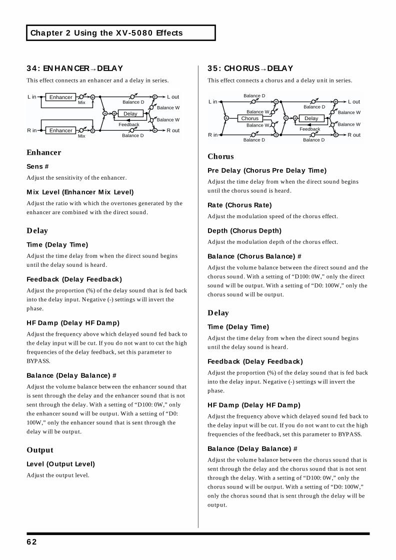
Chapter 2 Using the XV-5080 Effects
34: ENHANCER→DELAYThis effect connects an enhancer and a delay in series.fig.2-40
Enhancer
Sens #
Adjust the sensitivity of the enhancer.
Mix Level (Enhancer Mix Level)
Adjust the ratio with which the overtones generated by the enhancer are combined with the direct sound.
Delay
Time (Delay Time)
Adjust the time delay from when the direct sound begins until the delay sound is heard.
Feedback (Delay Feedback)
Adjust the proportion (%) of the delay sound that is fed back into the delay input. Negative (-) settings will invert the phase.
HF Damp (Delay HF Damp)
Adjust the frequency above which delayed sound fed back to the delay input will be cut. If you do not want to cut the high frequencies of the delay feedback, set this parameter to BYPASS.
Balance (Delay Balance) #
Adjust the volume balance between the enhancer sound that is sent through the delay and the enhancer sound that is not sent through the delay. With a setting of “D100: 0W,” only the enhancer sound will be output. With a setting of “D0: 100W,” only the enhancer sound that is sent through the delay will be output.
Output
Level (Output Level)
Adjust the output level.
35: CHORUS→DELAYThis effect connects a chorus and a delay unit in series.fig.2-41
Chorus
Pre Delay (Chorus Pre Delay Time)
Adjust the time delay from when the direct sound begins until the chorus sound is heard.
Rate (Chorus Rate)
Adjust the modulation speed of the chorus effect.
Depth (Chorus Depth)
Adjust the modulation depth of the chorus effect.
Balance (Chorus Balance) #
Adjust the volume balance between the direct sound and the chorus sound. With a setting of “D100: 0W,” only the direct sound will be output. With a setting of “D0: 100W,” only the chorus sound will be output.
Delay
Time (Delay Time)
Adjust the time delay from when the direct sound begins until the delay sound is heard.
Feedback (Delay Feedback)
Adjust the proportion (%) of the delay sound that is fed back into the delay input. Negative (-) settings will invert the phase.
HF Damp (Delay HF Damp)
Adjust the frequency above which delayed sound fed back to the delay input will be cut. If you do not want to cut the high frequencies of the feedback, set this parameter to BYPASS.
Balance (Delay Balance) #
Adjust the volume balance between the chorus sound that is sent through the delay and the chorus sound that is not sent through the delay. With a setting of “D100: 0W,” only the chorus sound will be output. With a setting of “D0: 100W,” only the chorus sound that is sent through the delay will be output.
Feedback
Delay
L in
R in
L out
R out
Mix
Mix
Enhancer
Enhancer
Balance W
Balance W
Balance D
Balance D
Feedback
Delay
L in
R in
L out
R out
Balance W
Balance W
Balance D
Balance D
ChorusBalance W
Balance W
Balance D
Balance D
62
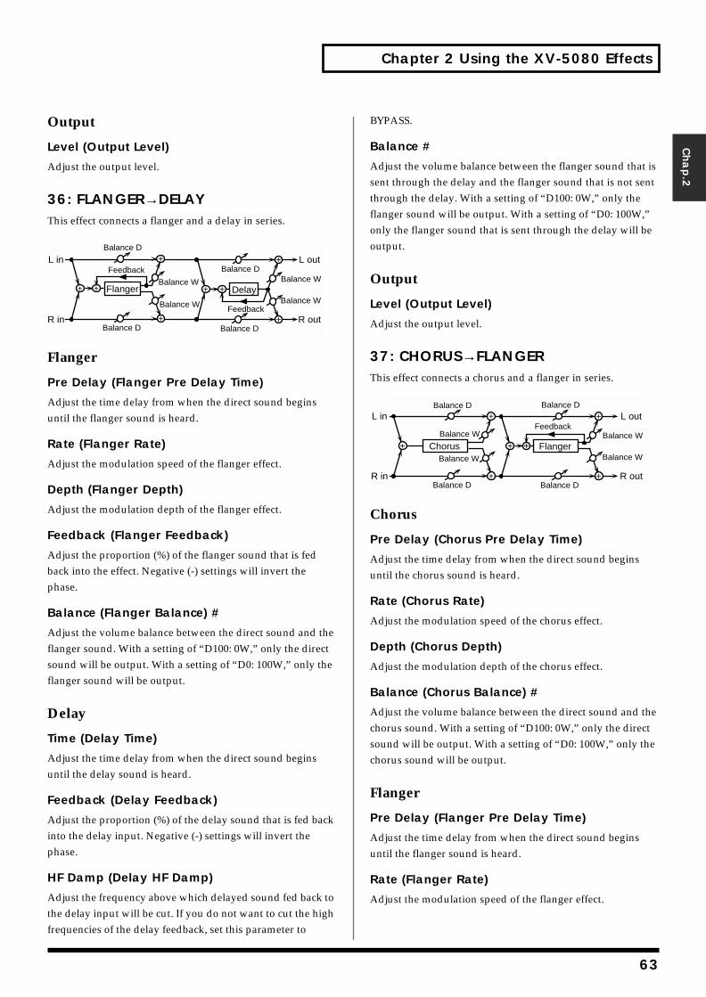
Chapter 2 Using the XV-5080 Effects
Chap.2
Output
Level (Output Level)
Adjust the output level.
36: FLANGER→DELAYThis effect connects a flanger and a delay in series.fig.2-42
Flanger
Pre Delay (Flanger Pre Delay Time)
Adjust the time delay from when the direct sound begins until the flanger sound is heard.
Rate (Flanger Rate)
Adjust the modulation speed of the flanger effect.
Depth (Flanger Depth)
Adjust the modulation depth of the flanger effect.
Feedback (Flanger Feedback)
Adjust the proportion (%) of the flanger sound that is fed back into the effect. Negative (-) settings will invert the phase.
Balance (Flanger Balance) #
Adjust the volume balance between the direct sound and the flanger sound. With a setting of “D100: 0W,” only the direct sound will be output. With a setting of “D0: 100W,” only the flanger sound will be output.
Delay
Time (Delay Time)
Adjust the time delay from when the direct sound begins until the delay sound is heard.
Feedback (Delay Feedback)
Adjust the proportion (%) of the delay sound that is fed back into the delay input. Negative (-) settings will invert the phase.
HF Damp (Delay HF Damp)
Adjust the frequency above which delayed sound fed back to the delay input will be cut. If you do not want to cut the high frequencies of the delay feedback, set this parameter to
BYPASS.
Balance #
Adjust the volume balance between the flanger sound that is sent through the delay and the flanger sound that is not sent through the delay. With a setting of “D100: 0W,” only the flanger sound will be output. With a setting of “D0: 100W,” only the flanger sound that is sent through the delay will be output.
Output
Level (Output Level)
Adjust the output level.
37: CHORUS→FLANGERThis effect connects a chorus and a flanger in series.fig.2-43
Chorus
Pre Delay (Chorus Pre Delay Time)
Adjust the time delay from when the direct sound begins until the chorus sound is heard.
Rate (Chorus Rate)
Adjust the modulation speed of the chorus effect.
Depth (Chorus Depth)
Adjust the modulation depth of the chorus effect.
Balance (Chorus Balance) #
Adjust the volume balance between the direct sound and the chorus sound. With a setting of “D100: 0W,” only the direct sound will be output. With a setting of “D0: 100W,” only the chorus sound will be output.
Flanger
Pre Delay (Flanger Pre Delay Time)
Adjust the time delay from when the direct sound begins until the flanger sound is heard.
Rate (Flanger Rate)
Adjust the modulation speed of the flanger effect.
Feedback
Delay
L in
R in
L out
R out
Balance W
Balance W
Balance D
Balance D
Flanger
Balance W
Balance W
Balance D
Balance D
Feedback
Feedback
Flanger
L in
R in
L out
R out
Balance W
Balance W
Balance D
Balance D
ChorusBalance W
Balance W
Balance D
Balance D
63
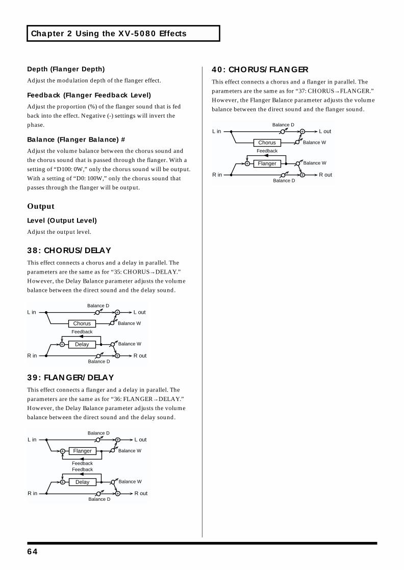
Chapter 2 Using the XV-5080 Effects
Depth (Flanger Depth)
Adjust the modulation depth of the flanger effect.
Feedback (Flanger Feedback Level)
Adjust the proportion (%) of the flanger sound that is fed back into the effect. Negative (-) settings will invert the phase.
Balance (Flanger Balance) #
Adjust the volume balance between the chorus sound and the chorus sound that is passed through the flanger. With a setting of “D100: 0W,” only the chorus sound will be output. With a setting of “D0: 100W,” only the chorus sound that passes through the flanger will be output.
Output
Level (Output Level)
Adjust the output level.
38: CHORUS/DELAYThis effect connects a chorus and a delay in parallel. The parameters are the same as for “35: CHORUS→DELAY.” However, the Delay Balance parameter adjusts the volume balance between the direct sound and the delay sound.fig.2-44
39: FLANGER/DELAYThis effect connects a flanger and a delay in parallel. The parameters are the same as for “36: FLANGER→DELAY.” However, the Delay Balance parameter adjusts the volume balance between the direct sound and the delay sound.fig.2-45
40: CHORUS/FLANGERThis effect connects a chorus and a flanger in parallel. The parameters are the same as for “37: CHORUS→FLANGER.” However, the Flanger Balance parameter adjusts the volume balance between the direct sound and the flanger sound.fig.2-46
R in R out
L in L out
Feedback
Balance W
Balance D
Balance W
Balance D
Chorus
Delay
R in R out
L in L out
FeedbackFeedback
Balance W
Balance D
Balance W
Balance D
Flanger
Delay
R in R out
L in L out
Feedback
Balance W
Balance D
Balance W
Balance D
Chorus
Flanger
64
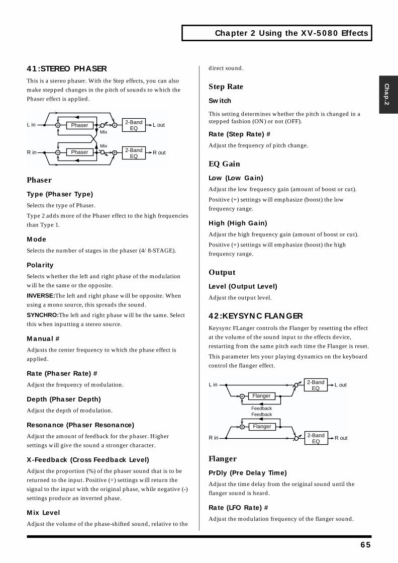
Chapter 2 Using the XV-5080 Effects
Chap.2
41:STEREO PHASERThis is a stereo phaser. With the Step effects, you can also make stepped changes in the pitch of sounds to which the Phaser effect is applied.fig.2-51
Phaser
Type (Phaser Type)
Selects the type of Phaser.
Type 2 adds more of the Phaser effect to the high frequencies than Type 1.
Mode
Selects the number of stages in the phaser (4/8-STAGE).
Polarity
Selects whether the left and right phase of the modulation will be the same or the opposite.
INVERSE:The left and right phase will be opposite. When using a mono source, this spreads the sound.
SYNCHRO:The left and right phase will be the same. Select this when inputting a stereo source.
Manual #
Adjusts the center frequency to which the phase effect is applied.
Rate (Phaser Rate) #
Adjust the frequency of modulation.
Depth (Phaser Depth)
Adjust the depth of modulation.
Resonance (Phaser Resonance)
Adjust the amount of feedback for the phaser. Higher settings will give the sound a stronger character.
X-Feedback (Cross Feedback Level)
Adjust the proportion (%) of the phaser sound that is to be returned to the input. Positive (+) settings will return the signal to the input with the original phase, while negative (-) settings produce an inverted phase.
Mix Level
Adjust the volume of the phase-shifted sound, relative to the
direct sound.
Step Rate
Switch
This setting determines whether the pitch is changed in a stepped fashion (ON) or not (OFF).
Rate (Step Rate) #
Adjust the frequency of pitch change.
EQ Gain
Low (Low Gain)
Adjust the low frequency gain (amount of boost or cut).
Positive (+) settings will emphasize (boost) the low frequency range.
High (High Gain)
Adjust the high frequency gain (amount of boost or cut).
Positive (+) settings will emphasize (boost) the high frequency range.
Output
Level (Output Level)
Adjust the output level.
42:KEYSYNC FLANGERKeysync FLanger controls the Flanger by resetting the effect at the volume of the sound input to the effects device, restarting from the same pitch each time the Flanger is reset.
This parameter lets your playing dynamics on the keyboard control the flanger effect.fig.2-52
Flanger
PrDly (Pre Delay Time)
Adjust the time delay from the original sound until the flanger sound is heard.
Rate (LFO Rate) #
Adjust the modulation frequency of the flanger sound.
R in R out
L in L outPhaserMix
2-BandEQ
Phaser 2-BandEQ
Mix
R in R out
L in L out
Flanger
FeedbackFeedback
Flanger
2-BandEQ
2-BandEQ
65
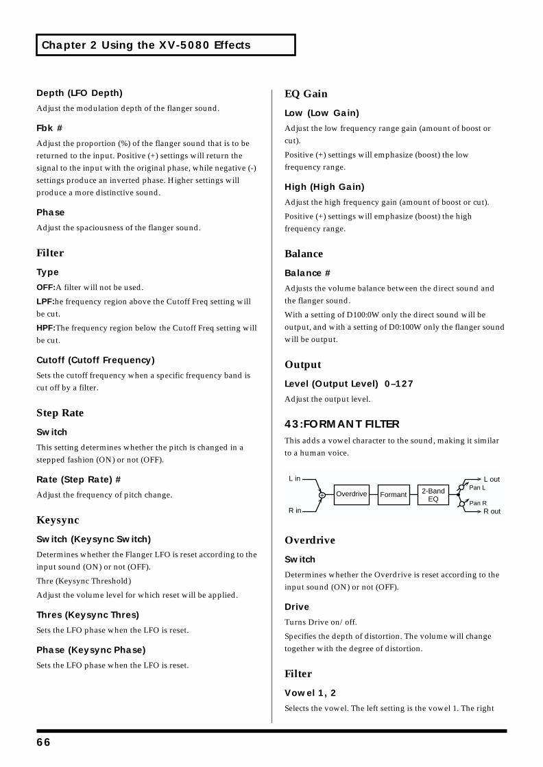
Chapter 2 Using the XV-5080 Effects
Depth (LFO Depth)
Adjust the modulation depth of the flanger sound.
Fbk #
Adjust the proportion (%) of the flanger sound that is to be returned to the input. Positive (+) settings will return the signal to the input with the original phase, while negative (-) settings produce an inverted phase. Higher settings will produce a more distinctive sound.
Phase
Adjust the spaciousness of the flanger sound.
Filter
Type
OFF:A filter will not be used.
LPF:he frequency region above the Cutoff Freq setting will be cut.
HPF:The frequency region below the Cutoff Freq setting will be cut.
Cutoff (Cutoff Frequency)
Sets the cutoff frequency when a specific frequency band is cut off by a filter.
Step Rate
Switch
This setting determines whether the pitch is changed in a stepped fashion (ON) or not (OFF).
Rate (Step Rate) #
Adjust the frequency of pitch change.
Keysync
Switch (Keysync Switch)
Determines whether the Flanger LFO is reset according to the input sound (ON) or not (OFF).
Thre (Keysync Threshold)
Adjust the volume level for which reset will be applied.
Thres (Keysync Thres)
Sets the LFO phase when the LFO is reset.
Phase (Keysync Phase)
Sets the LFO phase when the LFO is reset.
EQ Gain
Low (Low Gain)
Adjust the low frequency range gain (amount of boost or cut).
Positive (+) settings will emphasize (boost) the low frequency range.
High (High Gain)
Adjust the high frequency gain (amount of boost or cut).
Positive (+) settings will emphasize (boost) the high frequency range.
Balance
Balance #
Adjusts the volume balance between the direct sound and the flanger sound.
With a setting of D100:0W only the direct sound will be output, and with a setting of D0:100W only the flanger sound will be output.
Output
Level (Output Level) 0–127
Adjust the output level.
43:FORMANT FILTERThis adds a vowel character to the sound, making it similar to a human voice.
Overdrive
Switch
Determines whether the Overdrive is reset according to the input sound (ON) or not (OFF).
Drive
Turns Drive on/off.
Specifies the depth of distortion. The volume will change together with the degree of distortion.
Filter
Vowel 1, 2
Selects the vowel. The left setting is the vowel 1. The right
Formant 2-BandEQ
L in
R in
Overdrive
L out
R outPan R
Pan L
66
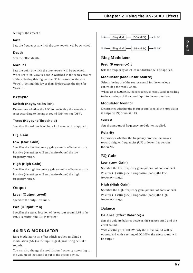
Chapter 2 Using the XV-5080 Effects
Chap.2
setting is the vowel 2.
Rate
Sets the frequency at which the two vowels will be switched.
Depth
Sets the effect depth.
Manual
Sets the point at which the two vowels will be switched. When set to 50, Vowels 1 and 2 switched in the same amount of time. Setting this higher than 50 increases the time for Vowel 1; setting this lower than 50 decreases the time for Vowel 1.
Keysync
Switch (Keysync Switch)
Determines whether the LFO for switching the vowels is reset according to the input sound (ON) or not (OFF).
Thres (Keysync Threshold)
Specifies the volume level for which reset will be applied.
EQ Gain
Low (Low Gain)
Specifies the low frequency gain (amount of boost or cut).
Positive (+) settings will emphasize (boost) the low frequency range.
High (High Gain)
Specifies the high frequency gain (amount of boost or cut).
Positive (+) settings will emphasize (boost) the high frequency range.
Output
Level (Output Level)
Specifies the output volume.
Pan (Output Pan)
Specifies the stereo location of the output sound. L64 is far left, 0 is center, and 63R is far right.
44:RING MODULATORRing Modulator is an effect which applies amplitude modulation (AM) to the input signal, producing bell-like sounds.
You can also change the modulation frequency according to the volume of the sound input to the effects device.
fig.2-54
Ring Modulator
Freq (Frequency) #
Sets the frequency at which modulation will be applied.
Modulator (Modulator Source)
Selects the input of the source sound for the envelope controlling the modulation.
When set to SOURCE, the frequency is modulated according to the envelope of the sound input to the multi-effects.
Modulator Monitor
Determines whether the input sound used as the modulator is output (ON) or not (OFF).
Sens #
Sets the amount of frequency modulation applied.
Polarity
Determines whether the frequency modulation moves towards higher frequencies (UP) or lower frequencies (DOWN).
EQ Gain
Low (Low Gain)
Specifies the low frequency gain (amount of boost or cut).
Positive (+) settings will emphasize (boost) the low frequency range.
High (High Gain)
Specifies the high frequency gain (amount of boost or cut).
Positive (+) settings will emphasize (boost) the high frequency range.
Balance
Balance (Effect Balance) #
Sets the volume balance between the source sound and the effect sound.
With a setting of D100:0W only the direct sound will be output, and with a setting of D0:100W the effect sound will be output.
L in
R in
L out
R out
Ring Mod
2-Band EQ
2-Band EQ
Ring Mod
67
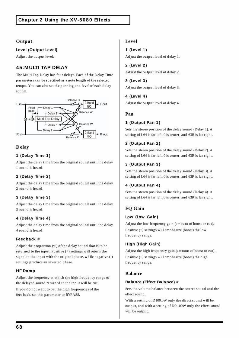
Chapter 2 Using the XV-5080 Effects
Output
Level (Output Level)
Adjust the output level.
45:MULTI TAP DELAYThe Multi Tap Delay has four delays. Each of the Delay Time parameters can be specified as a note length of the selected tempo. You can also set the panning and level of each delay sound.fig.2-55
Delay
1 (Delay Time 1)
Adjust the delay time from the original sound until the delay 1 sound is heard.
2 (Delay Time 2)
Adjust the delay time from the original sound until the delay 2 sound is heard.
3 (Delay Time 3)
Adjust the delay time from the original sound until the delay 3 sound is heard.
4 (Delay Time 4)
Adjust the delay time from the original sound until the delay 4 sound is heard.
Feedback #
Adjust the proportion (%) of the delay sound that is to be returned to the input. Positive (+) settings will return the signal to the input with the original phase, while negative (-) settings produce an inverted phase.
HF Damp
Adjust the frequency at which the high frequency range of the delayed sound returned to the input will be cut.
If you do not want to cut the high frequencies of the feedback, set this parameter to BYPASS.
Level
1 (Level 1)
Adjust the output level of delay 1.
2 (Level 2)
Adjust the output level of delay 2.
3 (Level 3)
Adjust the output level of delay 3.
4 (Level 4)
Adjust the output level of delay 4.
Pan
1 (Output Pan 1)
Sets the stereo position of the delay sound (Delay 1). A setting of L64 is far left, 0 is center, and 63R is far right.
2 (Output Pan 2)
Sets the stereo position of the delay sound (Delay 2). A setting of L64 is far left, 0 is center, and 63R is far right.
3 (Output Pan 3)
Sets the stereo position of the delay sound (Delay 3). A setting of L64 is far left, 0 is center, and 63R is far right.
4 (Output Pan 4)
Sets the stereo position of the delay sound (Delay 4). A setting of L64 is far left, 0 is center, and 63R is far right.
EQ Gain
Low (Low Gain)
Adjust the low frequency gain (amount of boost or cut).
Positive (+) settings will emphasize (boost) the low frequency range.
High (High Gain)
Adjust the high frequency gain (amount of boost or cut).
Positive (+) settings will emphasize (boost) the high frequency range.
Balance
Balance (Effect Balance) #
Sets the volume balance between the source sound and the effect sound.
With a setting of D100:0W only the direct sound will be output, and with a setting of D0:100W only the effect sound will be output.
L in
R in
L out
R out
Multi Tap Delay
Balance W
Balance D
Balance W
Balance D
Delay 1
Delay 3
Delay 4
Delay 2
Feedback
2-BandEQ
2-BandEQ
68
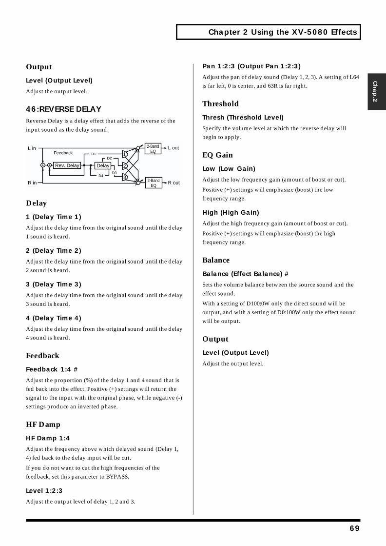
Chapter 2 Using the XV-5080 Effects
Chap.2
Output
Level (Output Level)
Adjust the output level.
46:REVERSE DELAYReverse Delay is a delay effect that adds the reverse of the input sound as the delay sound.fig.2-56
Delay
1 (Delay Time 1)
Adjust the delay time from the original sound until the delay 1 sound is heard.
2 (Delay Time 2)
Adjust the delay time from the original sound until the delay 2 sound is heard.
3 (Delay Time 3)
Adjust the delay time from the original sound until the delay 3 sound is heard.
4 (Delay Time 4)
Adjust the delay time from the original sound until the delay 4 sound is heard.
Feedback
Feedback 1:4 #
Adjust the proportion (%) of the delay 1 and 4 sound that is fed back into the effect. Positive (+) settings will return the signal to the input with the original phase, while negative (-) settings produce an inverted phase.
HF Damp
HF Damp 1:4
Adjust the frequency above which delayed sound (Delay 1, 4) fed back to the delay input will be cut.
If you do not want to cut the high frequencies of the feedback, set this parameter to BYPASS.
Level 1:2:3
Adjust the output level of delay 1, 2 and 3.
Pan 1:2:3 (Output Pan 1:2:3)
Adjust the pan of delay sound (Delay 1, 2, 3). A setting of L64 is far left, 0 is center, and 63R is far right.
Threshold
Thresh (Threshold Level)
Specify the volume level at which the reverse delay will begin to apply.
EQ Gain
Low (Low Gain)
Adjust the low frequency gain (amount of boost or cut).
Positive (+) settings will emphasize (boost) the low frequency range.
High (High Gain)
Adjust the high frequency gain (amount of boost or cut).
Positive (+) settings will emphasize (boost) the high frequency range.
Balance
Balance (Effect Balance) #
Sets the volume balance between the source sound and the effect sound.
With a setting of D100:0W only the direct sound will be output, and with a setting of D0:100W only the effect sound will be output.
Output
Level (Output Level)
Adjust the output level.
FeedbackL in
R in
Rev. Delay
L out
R out2-BandEQ
2-BandEQ
1
2
D1
Delay
3D3
D2
D4
69
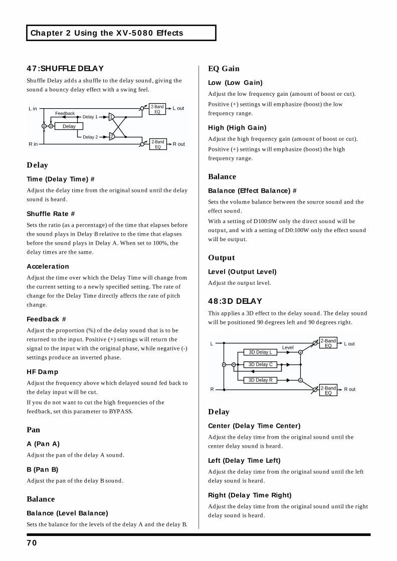
Chapter 2 Using the XV-5080 Effects
47:SHUFFLE DELAYShuffle Delay adds a shuffle to the delay sound, giving the sound a bouncy delay effect with a swing feel.fig.2-57
Delay
Time (Delay Time) #
Adjust the delay time from the original sound until the delay sound is heard.
Shuffle Rate #
Sets the ratio (as a percentage) of the time that elapses before the sound plays in Delay B relative to the time that elapses before the sound plays in Delay A. When set to 100%, the delay times are the same.
Acceleration
Adjust the time over which the Delay Time will change from the current setting to a newly specified setting. The rate of change for the Delay Time directly affects the rate of pitch change.
Feedback #
Adjust the proportion (%) of the delay sound that is to be returned to the input. Positive (+) settings will return the signal to the input with the original phase, while negative (-) settings produce an inverted phase.
HF Damp
Adjust the frequency above which delayed sound fed back to the delay input will be cut.
If you do not want to cut the high frequencies of the feedback, set this parameter to BYPASS.
Pan
A (Pan A)
Adjust the pan of the delay A sound.
B (Pan B)
Adjust the pan of the delay B sound.
Balance
Balance (Level Balance)
Sets the balance for the levels of the delay A and the delay B.
EQ Gain
Low (Low Gain)
Adjust the low frequency gain (amount of boost or cut).
Positive (+) settings will emphasize (boost) the low frequency range.
High (High Gain)
Adjust the high frequency gain (amount of boost or cut).
Positive (+) settings will emphasize (boost) the high frequency range.
Balance
Balance (Effect Balance) #
Sets the volume balance between the source sound and the effect sound.
With a setting of D100:0W only the direct sound will be output, and with a setting of D0:100W only the effect sound will be output.
Output
Level (Output Level)
Adjust the output level.
48:3D DELAYThis applies a 3D effect to the delay sound. The delay sound will be positioned 90 degrees left and 90 degrees right.fig.2-58
Delay
Center (Delay Time Center)
Adjust the delay time from the original sound until the center delay sound is heard.
Left (Delay Time Left)
Adjust the delay time from the original sound until the left delay sound is heard.
Right (Delay Time Right)
Adjust the delay time from the original sound until the right delay sound is heard.
FeedbackL in
R in
Delay
L out
R out2-BandEQ
2-BandEQ
1
2
Delay 1
Delay 2
L
R
L out
R out
3D Delay L
3D Delay R
3D Delay C
Level2-Band
EQ
2-BandEQ
70
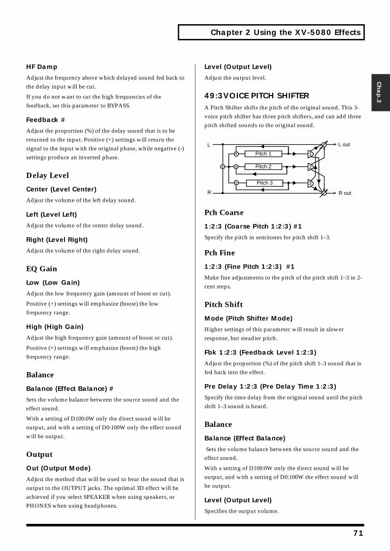
Chapter 2 Using the XV-5080 Effects
Chap.2
HF Damp
Adjust the frequency above which delayed sound fed back to the delay input will be cut.
If you do not want to cut the high frequencies of the feedback, set this parameter to BYPASS.
Feedback #
Adjust the proportion (%) of the delay sound that is to be returned to the input. Positive (+) settings will return the signal to the input with the original phase, while negative (-) settings produce an inverted phase.
Delay Level
Center (Level Center)
Adjust the volume of the left delay sound.
Left (Level Left)
Adjust the volume of the center delay sound.
Right (Level Right)
Adjust the volume of the right delay sound.
EQ Gain
Low (Low Gain)
Adjust the low frequency gain (amount of boost or cut).
Positive (+) settings will emphasize (boost) the low frequency range.
High (High Gain)
Adjust the high frequency gain (amount of boost or cut).
Positive (+) settings will emphasize (boost) the high frequency range.
Balance
Balance (Effect Balance) #
Sets the volume balance between the source sound and the effect sound.
With a setting of D100:0W only the direct sound will be output, and with a setting of D0:100W only the effect sound will be output.
Output
Out (Output Mode)
Adjust the method that will be used to hear the sound that is output to the OUTPUT jacks. The optimal 3D effect will be achieved if you select SPEAKER when using speakers, or PHONES when using headphones.
Level (Output Level)
Adjust the output level.
49:3VOICE PITCH SHIFTERA Pitch Shifter shifts the pitch of the original sound. This 3-voice pitch shifter has three pitch shifters, and can add three pitch shifted sounds to the original sound.fig.2-58
Pch Coarse
1:2:3 (Coarse Pitch 1:2:3) #1
Specify the pitch in semitones for pitch shift 1–3.
Pch Fine
1:2:3 (Fine Pitch 1:2:3) #1
Make fine adjustments to the pitch of the pitch shift 1–3 in 2-cent steps.
Pitch Shift
Mode (Pitch Shifter Mode)
Higher settings of this parameter will result in slower response, but steadier pitch.
Fbk 1:2:3 (Feedback Level 1:2:3)
Adjust the proportion (%) of the pitch shift 1–3 sound that is fed back into the effect.
Pre Delay 1:2:3 (Pre Delay Time 1:2:3)
Specify the time delay from the original sound until the pitch shift 1–3 sound is heard.
Balance
Balance (Effect Balance)
Sets the volume balance between the source sound and the effect sound.
With a setting of D100:0W only the direct sound will be output, and with a setting of D0:100W the effect sound will be output.
Level (Output Level)
Specifies the output volume.
L
R
Pitch 1
Pitch 3
Pitch 2
L out
R out
1
2
3
71
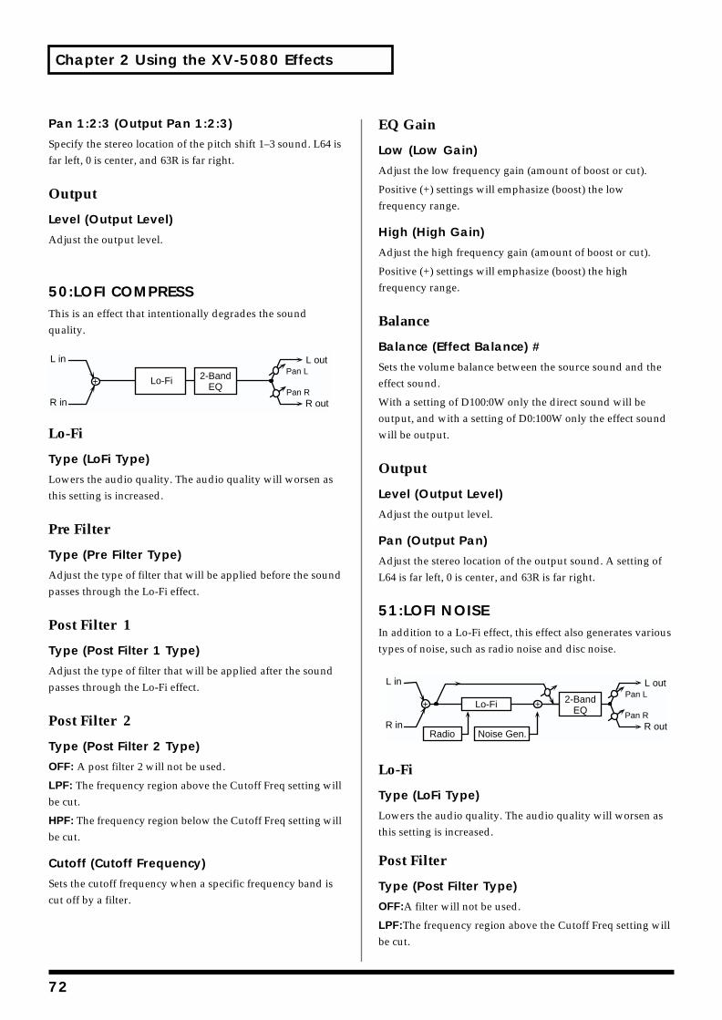
Chapter 2 Using the XV-5080 Effects
Pan 1:2:3 (Output Pan 1:2:3)
Specify the stereo location of the pitch shift 1–3 sound. L64 is far left, 0 is center, and 63R is far right.
Output
Level (Output Level)
Adjust the output level.
50:LOFI COMPRESSThis is an effect that intentionally degrades the sound quality.fig.2-60
Lo-Fi
Type (LoFi Type)
Lowers the audio quality. The audio quality will worsen as this setting is increased.
Pre Filter
Type (Pre Filter Type)
Adjust the type of filter that will be applied before the sound passes through the Lo-Fi effect.
Post Filter 1
Type (Post Filter 1 Type)
Adjust the type of filter that will be applied after the sound passes through the Lo-Fi effect.
Post Filter 2
Type (Post Filter 2 Type)
OFF: A post filter 2 will not be used.
LPF: The frequency region above the Cutoff Freq setting will be cut.
HPF: The frequency region below the Cutoff Freq setting will be cut.
Cutoff (Cutoff Frequency)
Sets the cutoff frequency when a specific frequency band is cut off by a filter.
EQ Gain
Low (Low Gain)
Adjust the low frequency gain (amount of boost or cut).
Positive (+) settings will emphasize (boost) the low frequency range.
High (High Gain)
Adjust the high frequency gain (amount of boost or cut).
Positive (+) settings will emphasize (boost) the high frequency range.
Balance
Balance (Effect Balance) #
Sets the volume balance between the source sound and the effect sound.
With a setting of D100:0W only the direct sound will be output, and with a setting of D0:100W only the effect sound will be output.
Output
Level (Output Level)
Adjust the output level.
Pan (Output Pan)
Adjust the stereo location of the output sound. A setting of L64 is far left, 0 is center, and 63R is far right.
51:LOFI NOISEIn addition to a Lo-Fi effect, this effect also generates various types of noise, such as radio noise and disc noise.fig.2-61
Lo-Fi
Type (LoFi Type)
Lowers the audio quality. The audio quality will worsen as this setting is increased.
Post Filter
Type (Post Filter Type)
OFF:A filter will not be used.
LPF:The frequency region above the Cutoff Freq setting will be cut.
Lo-Fi 2-BandEQ
L in
R in
L out
R outPan R
Pan L
Lo-Fi
Radio Noise Gen.
L in
R in
L out
R outPan R
Pan L2-BandEQ
72
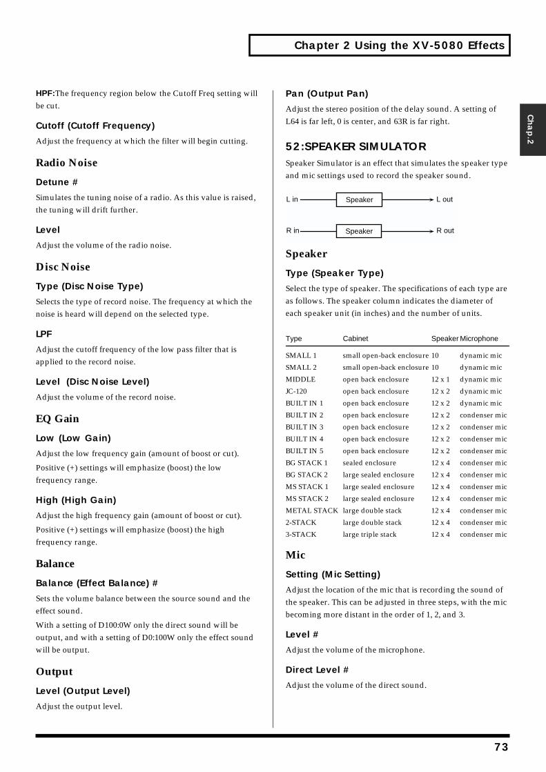
Chapter 2 Using the XV-5080 Effects
HPF:The frequency region bebe cut.
Cutoff (Cutoff Frequenc
Adjust the frequency at which
Radio Noise
Detune #
Simulates the tuning noise ofthe tuning will drift further.
Level
Adjust the volume of the radi
Disc Noise
Type (Disc Noise Type)
Selects the type of record noisnoise is heard will depend on
LPF
Adjust the cutoff frequency oapplied to the record noise.
Level (Disc Noise Leve
Adjust the volume of the reco
EQ Gain
Low (Low Gain)
Adjust the low frequency gai
Positive (+) settings will empfrequency range.
High (High Gain)
Adjust the high frequency ga
Positive (+) settings will empfrequency range.
Balance
Balance (Effect Balance
Sets the volume balance betweffect sound.
With a setting of D100:0W onoutput, and with a setting of will be output.
Output
Level (Output Level)
Adjust the output level.
Chap.2
low the Cutoff Freq setting will
y)
the filter will begin cutting.
a radio. As this value is raised,
o noise.
e. The frequency at which the the selected type.
f the low pass filter that is
l)
rd noise.
n (amount of boost or cut).
hasize (boost) the low
in (amount of boost or cut).
hasize (boost) the high
) #
een the source sound and the
ly the direct sound will be D0:100W only the effect sound
Pan (Output Pan)
Adjust the stereo position of the delay sound. A setting of L64 is far left, 0 is center, and 63R is far right.
52:SPEAKER SIMULATORSpeaker Simulator is an effect that simulates the speaker type and mic settings used to record the speaker sound.fig.2-62
Speaker
Type (Speaker Type)
Select the type of speaker. The specifications of each type are as follows. The speaker column indicates the diameter of each speaker unit (in inches) and the number of units.
Type Cabinet Speaker Microphone
SMALL 1 small open-back enclosure 10 dynamic mic
SMALL 2 small open-back enclosure 10 dynamic mic
MIDDLE open back enclosure 12 x 1 dynamic mic
JC-120 open back enclosure 12 x 2 dynamic mic
BUILT IN 1 open back enclosure 12 x 2 dynamic mic
BUILT IN 2 open back enclosure 12 x 2 condenser mic
BUILT IN 3 open back enclosure 12 x 2 condenser mic
BUILT IN 4 open back enclosure 12 x 2 condenser mic
BUILT IN 5 open back enclosure 12 x 2 condenser mic
BG STACK 1 sealed enclosure 12 x 4 condenser mic
BG STACK 2 large sealed enclosure 12 x 4 condenser mic
MS STACK 1 large sealed enclosure 12 x 4 condenser mic
MS STACK 2 large sealed enclosure 12 x 4 condenser mic
METAL STACK large double stack 12 x 4 condenser mic
2-STACK large double stack 12 x 4 condenser mic
3-STACK large triple stack 12 x 4 condenser mic
Mic
Setting (Mic Setting)
Adjust the location of the mic that is recording the sound of the speaker. This can be adjusted in three steps, with the mic becoming more distant in the order of 1, 2, and 3.
Level #
Adjust the volume of the microphone.
Direct Level #
Adjust the volume of the direct sound.
L in
R in
L out
R out
Speaker
Speaker
73
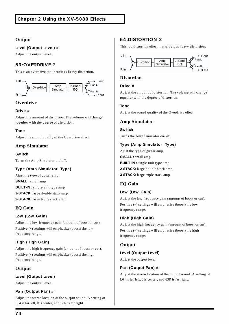
Chapter 2 Using the XV-5080 Effects
Output
Level (Output Level) #
Adjust the output level.
53:OVERDRIVE 2This is an overdrive that provides heavy distortion.fig.2-63
Overdrive
Drive #
Adjust the amount of distortion. The volume will change together with the degree of distortion.
Tone
Adjust the sound quality of the Overdrive effect.
Amp Simulator
Switch
Turns the Amp Simulator on/off.
Type (Amp Simulator Type)
Ajust the type of guitar amp.
SMALL : small amp
BUILT-IN : single-unit type amp
2-STACK: large double stack amp
3-STACK: large triple stack amp
EQ Gain
Low (Low Gain)
Adjust the low frequency gain (amount of boost or cut).
Positive (+) settings will emphasize (boost) the low frequency range.
High (High Gain)
Adjust the high frequency gain (amount of boost or cut).
Positive (+) settings will emphasize (boost) the high frequency range.
Output
Level (Output Level)
Adjust the output level.
Pan (Output Pan) #
Adjust the stereo location of the output sound. A setting of L64 is far left, 0 is center, and 63R is far right.
54:DISTORTION 2This is a distortion effect that provides heavy distortion.fig.2-64
Distortion
Drive #
Adjust the amount of distortion. The volume will change together with the degree of distortion.
Tone
Adjust the sound quality of the Overdrive effect.
Amp Simulator
Switch
Turns the Amp Simulator on/off.
Type (Amp Simulator Type)
Ajust the type of guitar amp.
SMALL : small amp
BUILT-IN : single-unit type amp
2-STACK: large double stack amp
3-STACK: large triple stack amp
EQ Gain
Low (Low Gain)
Adjust the low frequency gain (amount of boost or cut).
Positive (+) settings will emphasize (boost) the low frequency range.
High (High Gain)
Adjust the high frequency gain (amount of boost or cut).
Positive (+) settings will emphasize (boost) the high frequency range.
Output
Level (Output Level)
Adjust the output level.
Pan (Output Pan) #
Adjust the stereo location of the output sound. A setting of L64 is far left, 0 is center, and 63R is far right.
L in
R in
L out
R outPan R
Pan LAmpSimulator
2-BandEQ
Overdrive
L in
R in
L out
R outPan R
Pan LAmpSimulator
2-BandEQ
Distortion
74
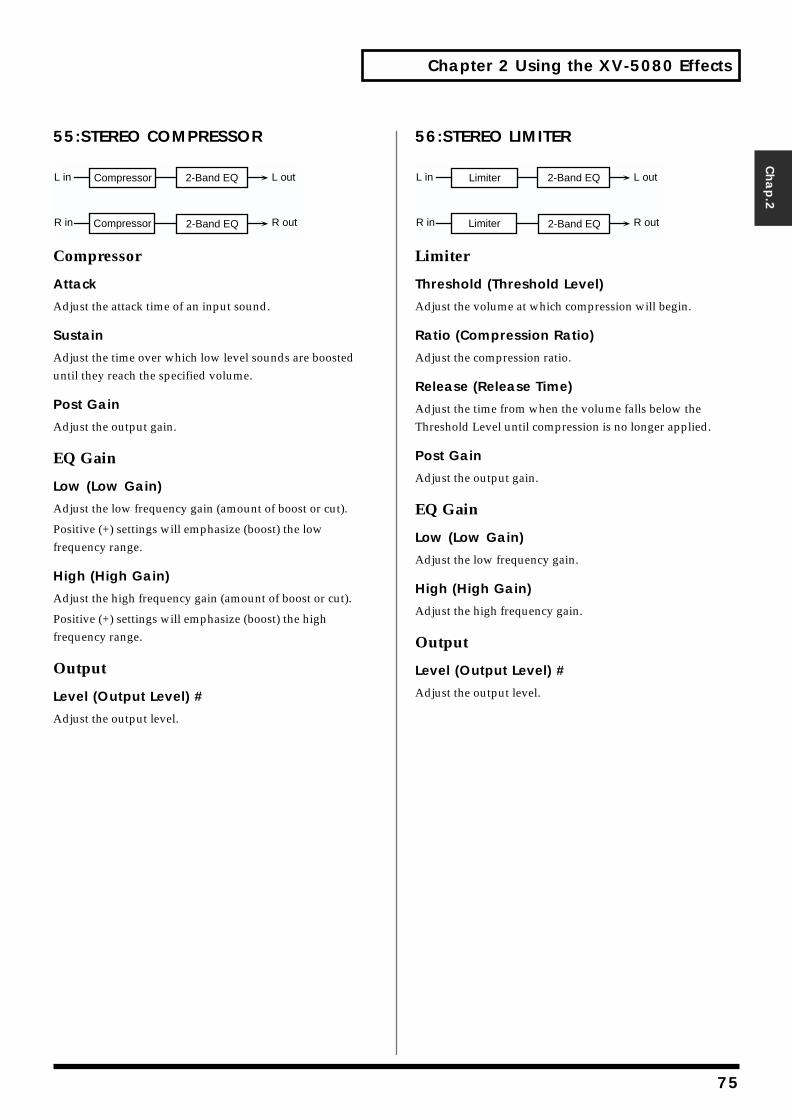
Chapter 2 Using the XV-5080 Effects
Chap.2
55:STEREO COMPRESSORfig.2-65
Compressor
Attack
Adjust the attack time of an input sound.
Sustain
Adjust the time over which low level sounds are boosted until they reach the specified volume.
Post Gain
Adjust the output gain.
EQ Gain
Low (Low Gain)
Adjust the low frequency gain (amount of boost or cut).
Positive (+) settings will emphasize (boost) the low frequency range.
High (High Gain)
Adjust the high frequency gain (amount of boost or cut).
Positive (+) settings will emphasize (boost) the high frequency range.
Output
Level (Output Level) #
Adjust the output level.
56:STEREO LIMITERfig.2-66
Limiter
Threshold (Threshold Level)
Adjust the volume at which compression will begin.
Ratio (Compression Ratio)
Adjust the compression ratio.
Release (Release Time)
Adjust the time from when the volume falls below the Threshold Level until compression is no longer applied.
Post Gain
Adjust the output gain.
EQ Gain
Low (Low Gain)
Adjust the low frequency gain.
High (High Gain)
Adjust the high frequency gain.
Output
Level (Output Level) #
Adjust the output level.
L in
R in
L out
R out
Compressor
2-Band EQ
2-Band EQ
Compressor
L in
R in
L out
R out
Limiter
2-Band EQ
2-Band EQ
Limiter
75
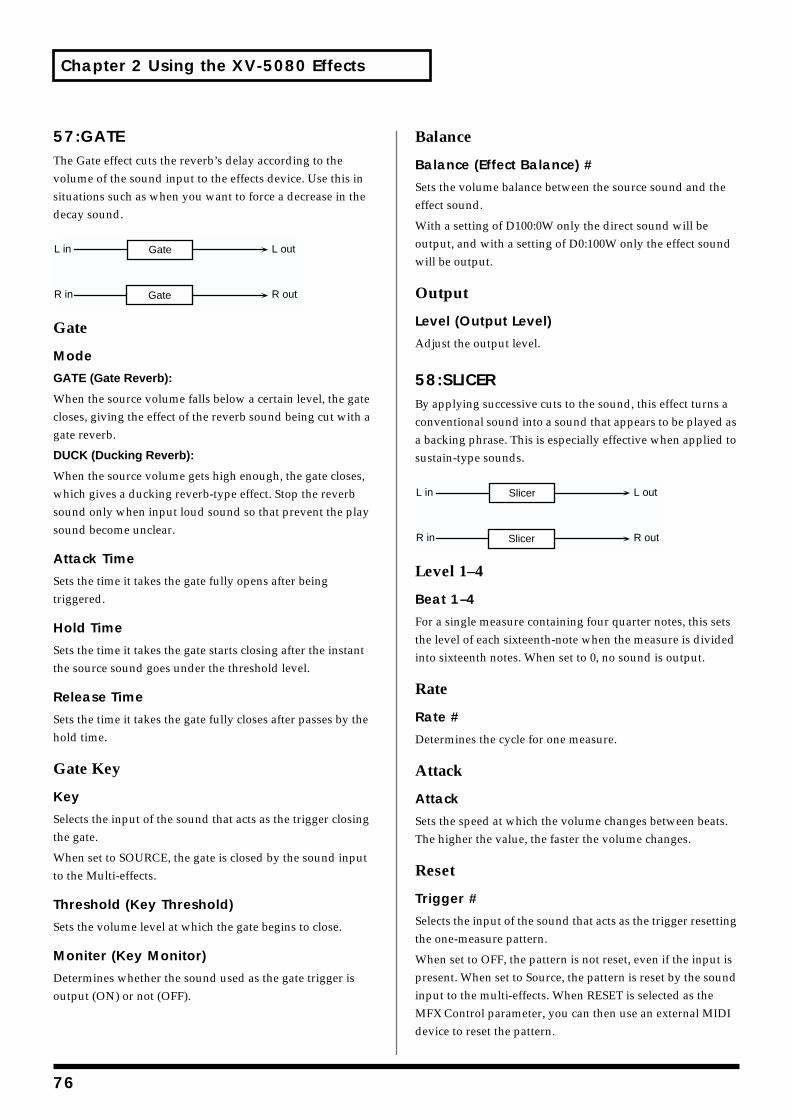
Chapter 2 Using the XV-5080 Effects
57:GATEThe Gate effect cuts the reverb’s delay according to the volume of the sound input to the effects device. Use this in situations such as when you want to force a decrease in the decay sound.fig.2-67
Gate
Mode
GATE (Gate Reverb):
When the source volume falls below a certain level, the gate closes, giving the effect of the reverb sound being cut with a gate reverb.
DUCK (Ducking Reverb):
When the source volume gets high enough, the gate closes, which gives a ducking reverb-type effect. Stop the reverb sound only when input loud sound so that prevent the play sound become unclear.
Attack Time
Sets the time it takes the gate fully opens after being triggered.
Hold Time
Sets the time it takes the gate starts closing after the instant the source sound goes under the threshold level.
Release Time
Sets the time it takes the gate fully closes after passes by the hold time.
Gate Key
Key
Selects the input of the sound that acts as the trigger closing the gate.
When set to SOURCE, the gate is closed by the sound input to the Multi-effects.
Threshold (Key Threshold)
Sets the volume level at which the gate begins to close.
Moniter (Key Monitor)
Determines whether the sound used as the gate trigger is output (ON) or not (OFF).
Balance
Balance (Effect Balance) #
Sets the volume balance between the source sound and the effect sound.
With a setting of D100:0W only the direct sound will be output, and with a setting of D0:100W only the effect sound will be output.
Output
Level (Output Level)
Adjust the output level.
58:SLICERBy applying successive cuts to the sound, this effect turns a conventional sound into a sound that appears to be played as a backing phrase. This is especially effective when applied to sustain-type sounds.fig.2-68
Level 1–4
Beat 1–4
For a single measure containing four quarter notes, this sets the level of each sixteenth-note when the measure is divided into sixteenth notes. When set to 0, no sound is output.
Rate
Rate #
Determines the cycle for one measure.
Attack
Attack
Sets the speed at which the volume changes between beats. The higher the value, the faster the volume changes.
Reset
Trigger #
Selects the input of the sound that acts as the trigger resetting the one-measure pattern.
When set to OFF, the pattern is not reset, even if the input is present. When set to Source, the pattern is reset by the sound input to the multi-effects. When RESET is selected as the MFX Control parameter, you can then use an external MIDI device to reset the pattern.
L in
R in
L out
R out
Gate
Gate
L in
R in
L out
R out
Slicer
Slicer
76
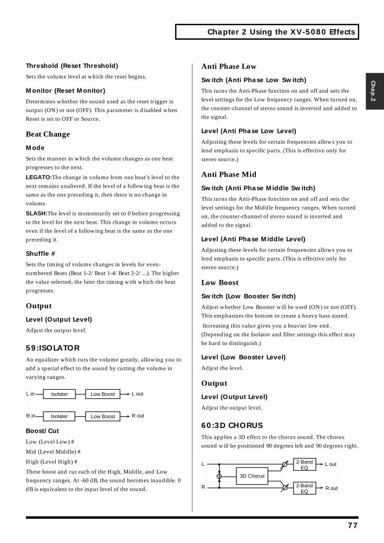
Chapter 2 Using the XV-5080 Effects
Chap.2
Threshold (Reset Threshold)
Sets the volume level at which the reset begins.
Monitor (Reset Monitor)
Determines whether the sound used as the reset trigger is output (ON) or not (OFF). This parameter is disabled when Reset is set to OFF or Source.
Beat Change
Mode
Sets the manner in which the volume changes as one beat progresses to the next.
LEGATO:The change in volume from one beat’s level to the next remains unaltered. If the level of a following beat is the same as the one preceding it, then there is no change in volume.
SLASH:The level is momentarily set to 0 before progressing to the level for the next beat. This change in volume occurs even if the level of a following beat is the same as the one preceding it.
Shuffle #
Sets the timing of volume changes in levels for even-numbered Beats (Beat 1-2/Beat 1-4/Beat 2-2/...). The higher the value selected, the later the timing with which the beat progresses.
Output
Level (Output Level)
Adjust the output level.
59:ISOLATORAn equalizer which cuts the volume greatly, allowing you to add a special effect to the sound by cutting the volume in varying ranges.fig.2-69
Boost/Cut
Low (Level Low) #
Mid (Level Middle) #
High (Level High) #
These boost and cut each of the High, Middle, and Low frequency ranges. At -60 dB, the sound becomes inaudible. 0 dB is equivalent to the input level of the sound.
Anti Phase Low
Switch (Anti Phase Low Switch)
This turns the Anti-Phase function on and off and sets the level settings for the Low frequency ranges. When turned on, the counter-channel of stereo sound is inverted and added to the signal.
Level (Anti Phase Low Level)
Adjusting these levels for certain frequencies allows you to lend emphasis to specific parts. (This is effective only for stereo source.)
Anti Phase Mid
Switch (Anti Phase Middle Switch)
This turns the Anti-Phase function on and off and sets the level settings for the Middle frequency ranges. When turned on, the counter-channel of stereo sound is inverted and added to the signal.
Level (Anti Phase Middle Level)
Adjusting these levels for certain frequencies allows you to lend emphasis to specific parts. (This is effective only for stereo source.)
Low Boost
Switch (Low Booster Switch)
Adjust whether Low Booster will be used (ON) or not (OFF). This emphasizes the bottom to create a heavy bass sound.
Increasing this value gives you a heavier low end. (Depending on the Isolator and filter settings this effect may be hard to distinguish.)
Level (Low Booster Level)
Adjust the level.
Output
Level (Output Level)
Adjust the output level.
60:3D CHORUSThis applies a 3D effect to the chorus sound. The chorus sound will be positioned 90 degrees left and 90 degrees right.fig.2-70
L in
R in
L out
R out
Isolater
Low Boost
Low Boost
Isolater
L
R
3D Chorus
2-BandEQ
2-BandEQ
R out
L out
77
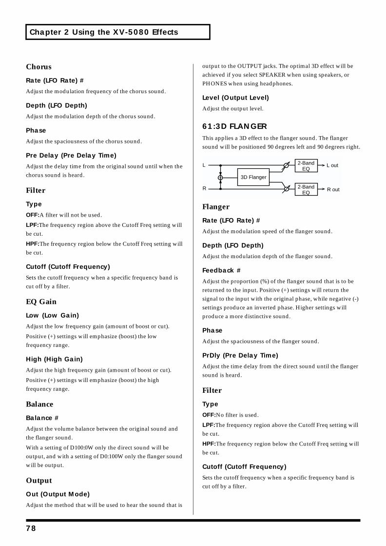
Chapter 2 Using the XV-5080 Effects
Chorus
Rate (LFO Rate) #
Adjust the modulation frequency of the chorus sound.
Depth (LFO Depth)
Adjust the modulation depth of the chorus sound.
Phase
Adjust the spaciousness of the chorus sound.
Pre Delay (Pre Delay Time)
Adjust the delay time from the original sound until when the chorus sound is heard.
Filter
Type
OFF:A filter will not be used.
LPF:The frequency region above the Cutoff Freq setting will be cut.
HPF:The frequency region below the Cutoff Freq setting will be cut.
Cutoff (Cutoff Frequency)
Sets the cutoff frequency when a specific frequency band is cut off by a filter.
EQ Gain
Low (Low Gain)
Adjust the low frequency gain (amount of boost or cut).
Positive (+) settings will emphasize (boost) the low frequency range.
High (High Gain)
Adjust the high frequency gain (amount of boost or cut).
Positive (+) settings will emphasize (boost) the high frequency range.
Balance
Balance #
Adjust the volume balance between the original sound and the flanger sound.
With a setting of D100:0W only the direct sound will be output, and with a setting of D0:100W only the flanger sound will be output.
Output
Out (Output Mode)
Adjust the method that will be used to hear the sound that is
output to the OUTPUT jacks. The optimal 3D effect will be achieved if you select SPEAKER when using speakers, or PHONES when using headphones.
Level (Output Level)
Adjust the output level.
61:3D FLANGERThis applies a 3D effect to the flanger sound. The flanger sound will be positioned 90 degrees left and 90 degrees right.fig.2-71
Flanger
Rate (LFO Rate) #
Adjust the modulation speed of the flanger sound.
Depth (LFO Depth)
Adjust the modulation depth of the flanger sound.
Feedback #
Adjust the proportion (%) of the flanger sound that is to be returned to the input. Positive (+) settings will return the signal to the input with the original phase, while negative (-) settings produce an inverted phase. Higher settings will produce a more distinctive sound.
Phase
Adjust the spaciousness of the flanger sound.
PrDly (Pre Delay Time)
Adjust the time delay from the direct sound until the flanger sound is heard.
Filter
Type
OFF:No filter is used.
LPF:The frequency region above the Cutoff Freq setting will be cut.
HPF:The frequency region below the Cutoff Freq setting will be cut.
Cutoff (Cutoff Frequency)
Sets the cutoff frequency when a specific frequency band is cut off by a filter.
L
R
3D Flanger
2-BandEQ
2-BandEQ
R out
L out
78
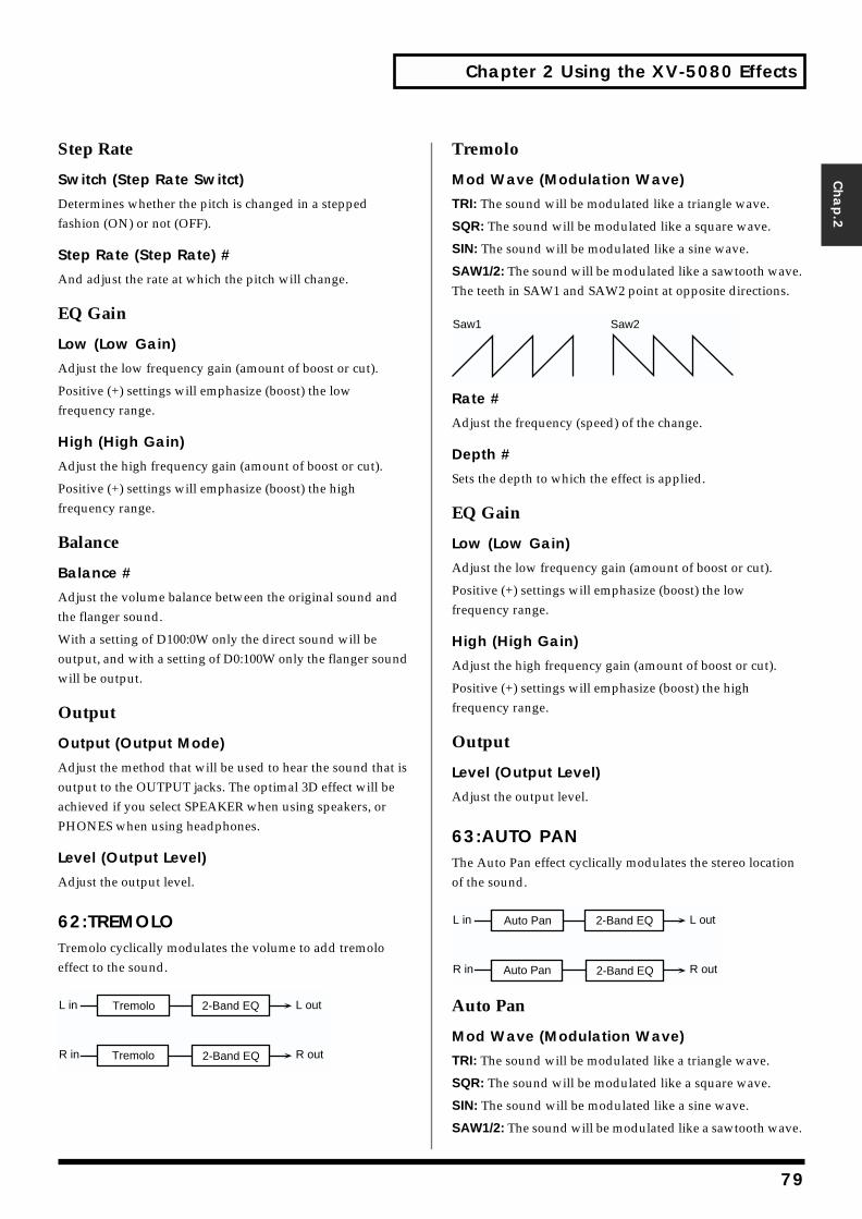
Chapter 2 Using the XV-5080 Effects
Chap.2
Step Rate
Switch (Step Rate Switct)
Determines whether the pitch is changed in a stepped fashion (ON) or not (OFF).
Step Rate (Step Rate) #
And adjust the rate at which the pitch will change.
EQ Gain
Low (Low Gain)
Adjust the low frequency gain (amount of boost or cut).
Positive (+) settings will emphasize (boost) the low frequency range.
High (High Gain)
Adjust the high frequency gain (amount of boost or cut).
Positive (+) settings will emphasize (boost) the high frequency range.
Balance
Balance #
Adjust the volume balance between the original sound and the flanger sound.
With a setting of D100:0W only the direct sound will be output, and with a setting of D0:100W only the flanger sound will be output.
Output
Output (Output Mode)
Adjust the method that will be used to hear the sound that is output to the OUTPUT jacks. The optimal 3D effect will be achieved if you select SPEAKER when using speakers, or PHONES when using headphones.
Level (Output Level)
Adjust the output level.
62:TREMOLOTremolo cyclically modulates the volume to add tremolo effect to the sound.fig.2-72
Tremolo
Mod Wave (Modulation Wave)
TRI: The sound will be modulated like a triangle wave.
SQR: The sound will be modulated like a square wave.
SIN: The sound will be modulated like a sine wave.
SAW1/2: The sound will be modulated like a sawtooth wave. The teeth in SAW1 and SAW2 point at opposite directions.fig.2-72a
Rate #
Adjust the frequency (speed) of the change.
Depth #
Sets the depth to which the effect is applied.
EQ Gain
Low (Low Gain)
Adjust the low frequency gain (amount of boost or cut).
Positive (+) settings will emphasize (boost) the low frequency range.
High (High Gain)
Adjust the high frequency gain (amount of boost or cut).
Positive (+) settings will emphasize (boost) the high frequency range.
Output
Level (Output Level)
Adjust the output level.
63:AUTO PANThe Auto Pan effect cyclically modulates the stereo location of the sound.fig.2-73
Auto Pan
Mod Wave (Modulation Wave)
TRI: The sound will be modulated like a triangle wave.
SQR: The sound will be modulated like a square wave.
SIN: The sound will be modulated like a sine wave.
SAW1/2: The sound will be modulated like a sawtooth wave.
L in
R in
L out
R out
Tremolo
2-Band EQ
2-Band EQ
Tremolo
Saw1 Saw2
L in
R in
L out
R out
Auto Pan
2-Band EQ
2-Band EQ
Auto Pan
79
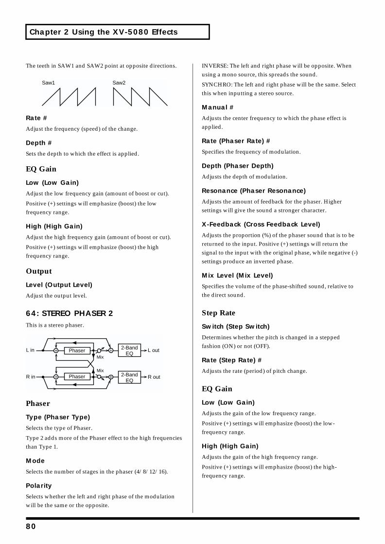
Chapter 2 Using the XV-5080 Effects
The teeth in SAW1 and SAW2 point at opposite directions.fig.2-73a
Rate #
Adjust the frequency (speed) of the change.
Depth #
Sets the depth to which the effect is applied.
EQ Gain
Low (Low Gain)
Adjust the low frequency gain (amount of boost or cut).
Positive (+) settings will emphasize (boost) the low frequency range.
High (High Gain)
Adjust the high frequency gain (amount of boost or cut).
Positive (+) settings will emphasize (boost) the high frequency range.
Output
Level (Output Level)
Adjust the output level.
64: STEREO PHASER 2This is a stereo phaser.fig.02-064m.e
Phaser
Type (Phaser Type)
Selects the type of Phaser.
Type 2 adds more of the Phaser effect to the high frequencies than Type 1.
Mode
Selects the number of stages in the phaser (4/8/12/16).
Polarity
Selects whether the left and right phase of the modulation will be the same or the opposite.
INVERSE: The left and right phase will be opposite. When using a mono source, this spreads the sound.
SYNCHRO: The left and right phase will be the same. Select this when inputting a stereo source.
Manual #
Adjusts the center frequency to which the phase effect is applied.
Rate (Phaser Rate) #
Specifies the frequency of modulation.
Depth (Phaser Depth)
Adjusts the depth of modulation.
Resonance (Phaser Resonance)
Adjusts the amount of feedback for the phaser. Higher settings will give the sound a stronger character.
X-Feedback (Cross Feedback Level)
Adjusts the proportion (%) of the phaser sound that is to be returned to the input. Positive (+) settings will return the signal to the input with the original phase, while negative (-) settings produce an inverted phase.
Mix Level (Mix Level)
Specifies the volume of the phase-shifted sound, relative to the direct sound.
Step Rate
Switch (Step Switch)
Determines whether the pitch is changed in a stepped fashion (ON) or not (OFF).
Rate (Step Rate) #
Adjusts the rate (period) of pitch change.
EQ Gain
Low (Low Gain)
Adjusts the gain of the low frequency range.
Positive (+) settings will emphasize (boost) the low-frequency range.
High (High Gain)
Adjusts the gain of the high frequency range.
Positive (+) settings will emphasize (boost) the high-frequency range.
Saw1 Saw2
R in R out
L in L outPhaserMix
2-BandEQ
Phaser 2-BandEQ
Mix
80
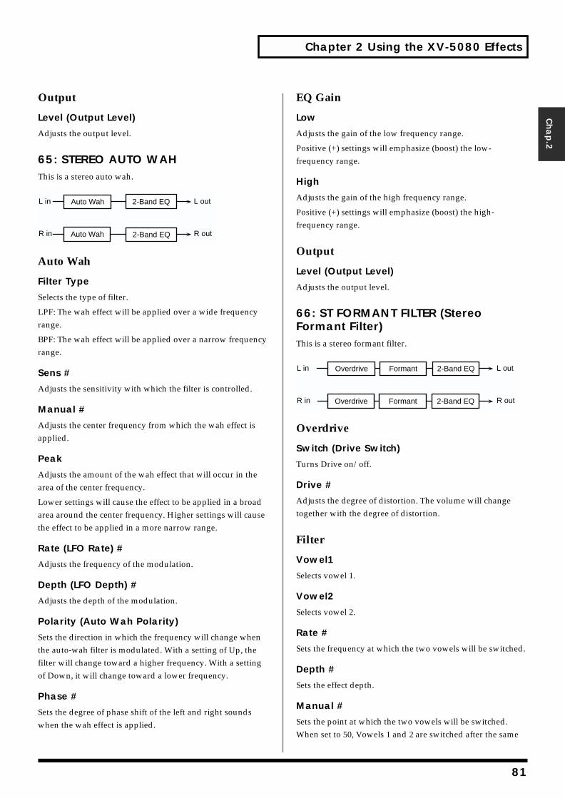
Chapter 2 Using the XV-5080 Effects
Chap.2
Output
Level (Output Level)
Adjusts the output level.
65: STEREO AUTO WAHThis is a stereo auto wah.fig.02-065m.e
Auto Wah
Filter Type
Selects the type of filter.
LPF: The wah effect will be applied over a wide frequency range.
BPF: The wah effect will be applied over a narrow frequency range.
Sens #
Adjusts the sensitivity with which the filter is controlled.
Manual #
Adjusts the center frequency from which the wah effect is applied.
Peak
Adjusts the amount of the wah effect that will occur in the area of the center frequency.
Lower settings will cause the effect to be applied in a broad area around the center frequency. Higher settings will cause the effect to be applied in a more narrow range.
Rate (LFO Rate) #
Adjusts the frequency of the modulation.
Depth (LFO Depth) #
Adjusts the depth of the modulation.
Polarity (Auto Wah Polarity)
Sets the direction in which the frequency will change when the auto-wah filter is modulated. With a setting of Up, the filter will change toward a higher frequency. With a setting of Down, it will change toward a lower frequency.
Phase #
Sets the degree of phase shift of the left and right sounds when the wah effect is applied.
EQ Gain
Low
Adjusts the gain of the low frequency range.
Positive (+) settings will emphasize (boost) the low-frequency range.
High
Adjusts the gain of the high frequency range.
Positive (+) settings will emphasize (boost) the high-frequency range.
Output
Level (Output Level)
Adjusts the output level.
66: ST FORMANT FILTER (Stereo Formant Filter)This is a stereo formant filter.fig.02-066m.e
Overdrive
Switch (Drive Switch)
Turns Drive on/off.
Drive #
Adjusts the degree of distortion. The volume will change together with the degree of distortion.
Filter
Vowel1
Selects vowel 1.
Vowel2
Selects vowel 2.
Rate #
Sets the frequency at which the two vowels will be switched.
Depth #
Sets the effect depth.
Manual #
Sets the point at which the two vowels will be switched. When set to 50, Vowels 1 and 2 are switched after the same
L in
R in
L out
R out
Auto Wah
2-Band EQ
2-Band EQ
Auto Wah
L in
R in
L out
R out
2-Band EQ
2-Band EQ
Overdrive
Overdrive
Formant
Formant
81
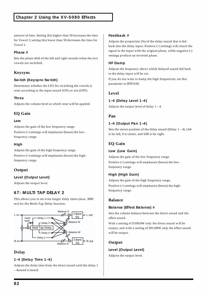
Chapter 2 Using the XV-5080 Effects
amount of time. Setting this higher than 50 increases the time for Vowel 1; setting this lower than 50 decreases the time for Vowel 1.
Phase #
Sets the phase shift of the left and right sounds when the two vowels are switched.
Keysync
Switch (Keysync Switch)
Determines whether the LFO for switching the vowels is reset according to the input sound (ON) or not (OFF).
Thres
Adjusts the volume level at which reset will be applied.
EQ Gain
Low
Adjusts the gain of the low frequency range.
Positive (+) settings will emphasize (boost) the low-frequency range.
High
Adjusts the gain of the high frequency range.
Positive (+) settings will emphasize (boost) the high-frequency range.
Output
Level (Output Level)
Adjusts the output level.
67: MULTI TAP DELAY 2This allows you to set even longer delay times (max. 3000 ms) for the Multi-Tap Delay function.fig.02-067m.e
Delay
1–4 (Delay Time 1–4)
Adjusts the delay time from the direct sound until the delay 1 – 4sound is heard.
Feedback #
Adjusts the proportion (%) of the delay sound that is fed back into the delay input. Positive (+) settings will return the signal to the input with the original phase, while negative (-) settings produce an inverted phase.
HF Damp
Adjusts the frequency above which delayed sound fed back to the delay input will be cut.
If you do not want to damp the high frequencies, set this parameter to BYPASS.
Level
1–4 (Delay Level 1–4)
Adjusts the output level of delay 1 – 4.
Pan
1–4 (Output Pan 1–4)
Sets the stereo position of the delay sound (Delay 1 – 4). L64 is far left, 0 is center, and 63R is far right.
EQ Gain
Low (Low Gain)
Adjusts the gain of the low frequency range.
Positive (+) settings will emphasize (boost) the low-frequency range.
High (High Gain)
Adjusts the gain of the high frequency range.
Positive (+) settings will emphasize (boost) the high-frequency range.
Balance
Balance (Effect Balance) #
Sets the volume balance between the direct sound and the effect sound.
With a setting of D100:0W only the direct sound will be output, and with a setting of D0:100W only the effect sound will be output.
Output
Level (Output Level)
Adjusts the output level.
L in
R in
L out
R out
Multi Tap Delay
Balance W
Balance D
Balance W
Balance D
Delay 1
Delay 3
Delay 4
Delay 2
Feedback
2-BandEQ
2-BandEQ
82
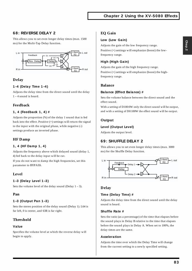
Chapter 2 Using the XV-5080 Effects
Chap.2
68: REVERSE DELAY 2This allows you to set even longer delay times (max. 1500 ms) for the Multi-Tap Delay function.fig.02-068m.e
Delay
1–4 (Delay Time 1–4)
Adjusts the delay time from the direct sound until the delay 1 – 4 sound is heard.
Feedback
1, 4 (Feedback 1, 4) #
Adjusts the proportion (%) of the delay 1 sound that is fed back into the effect. Positive (+) settings will return the signal to the input with the original phase, while negative (-) settings produce an inverted phase.
HF Damp
1, 4 (HF Damp 1, 4)
Adjusts the frequency above which delayed sound (delay 1, 4) fed back to the delay input will be cut.
If you do not want to damp the high frequencies, set this parameter to BYPASS.
Level
1–3 (Delay Level 1–3)
Sets the volume level of the delay sound (Delay 1 – 3).
Pan
1–3 (Output Pan 1–3)
Sets the stereo position of the delay sound (Delay 1). L64 is far left, 0 is center, and 63R is far right.
Threshold
Value
Specifies the volume level at which the reverse delay will begin to apply.
EQ Gain
Low (Low Gain)
Adjusts the gain of the low frequency range.
Positive (+) settings will emphasize (boost) the low-frequency range.
High (High Gain)
Adjusts the gain of the high frequency range.
Positive (+) settings will emphasize (boost) the high-frequency range.
Balance
Balance (Effect Balance) #
Sets the volume balance between the direct sound and the effect sound.
With a setting of D100:0W only the direct sound will be output, and with a setting of D0:100W the effect sound will be output.
Output
Level (Output Level)
Adjusts the output level.
69: SHUFFLE DELAY 2This allows you to set even longer delay times (max. 3000 ms) for the Shuffle Delay function.fig.02-069m.e
Delay
Time (Delay Time) #
Adjusts the delay time from the direct sound until the delay sound is heard.
Shuffle Rate #
Sets the ratio (as a percentage) of the time that elapses before the sound plays in Delay B relative to the time that elapses before the sound plays in Delay A. When set to 100%, the delay times are the same.
Acceleration
Adjusts the time over which the Delay Time will change from the current setting to a newly specified setting.
FeedbackL in
R in
Rev. Delay
L out
R out2-BandEQ
2-BandEQ
1
2
D1
Delay
3D3
D2
D4
FeedbackL in
R in
Delay
L out
R out2-BandEQ
2-BandEQ
1
2
Delay 1
Delay 2
83
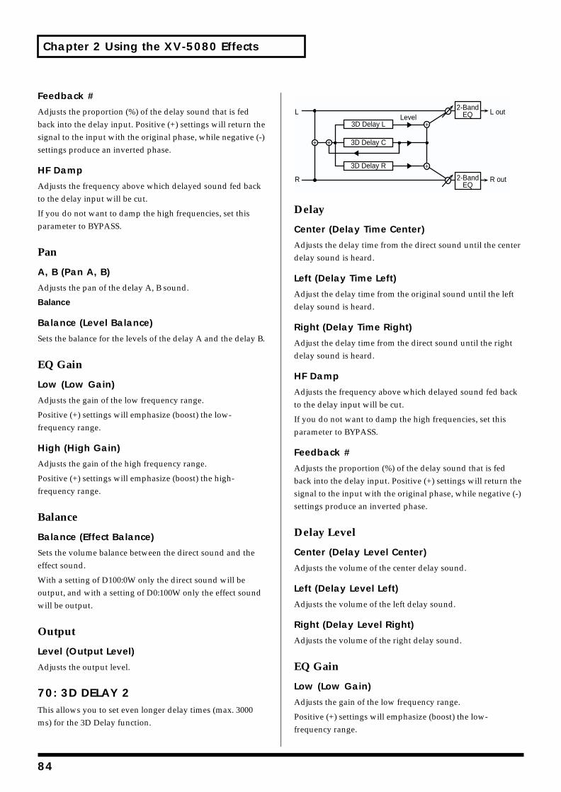
Chapter 2 Using the XV-5080 Effects
Feedback #
Adjusts the proportion (%) of the delay sound that is fed back into the delay input. Positive (+) settings will return the signal to the input with the original phase, while negative (-) settings produce an inverted phase.
HF Damp
Adjusts the frequency above which delayed sound fed back to the delay input will be cut.
If you do not want to damp the high frequencies, set this parameter to BYPASS.
Pan
A, B (Pan A, B)
Adjusts the pan of the delay A, B sound.
Balance
Balance (Level Balance)
Sets the balance for the levels of the delay A and the delay B.
EQ Gain
Low (Low Gain)
Adjusts the gain of the low frequency range.
Positive (+) settings will emphasize (boost) the low-frequency range.
High (High Gain)
Adjusts the gain of the high frequency range.
Positive (+) settings will emphasize (boost) the high-frequency range.
Balance
Balance (Effect Balance)
Sets the volume balance between the direct sound and the effect sound.
With a setting of D100:0W only the direct sound will be output, and with a setting of D0:100W only the effect sound will be output.
Output
Level (Output Level)
Adjusts the output level.
70: 3D DELAY 2This allows you to set even longer delay times (max. 3000 ms) for the 3D Delay function.
fig.02-070m.e
Delay
Center (Delay Time Center)
Adjusts the delay time from the direct sound until the center delay sound is heard.
Left (Delay Time Left)
Adjust the delay time from the original sound until the left delay sound is heard.
Right (Delay Time Right)
Adjust the delay time from the direct sound until the right delay sound is heard.
HF Damp
Adjusts the frequency above which delayed sound fed back to the delay input will be cut.
If you do not want to damp the high frequencies, set this parameter to BYPASS.
Feedback #
Adjusts the proportion (%) of the delay sound that is fed back into the delay input. Positive (+) settings will return the signal to the input with the original phase, while negative (-) settings produce an inverted phase.
Delay Level
Center (Delay Level Center)
Adjusts the volume of the center delay sound.
Left (Delay Level Left)
Adjusts the volume of the left delay sound.
Right (Delay Level Right)
Adjusts the volume of the right delay sound.
EQ Gain
Low (Low Gain)
Adjusts the gain of the low frequency range.
Positive (+) settings will emphasize (boost) the low-frequency range.
L
R
L out
R out
3D Delay L
3D Delay R
3D Delay C
Level2-Band
EQ
2-BandEQ
84
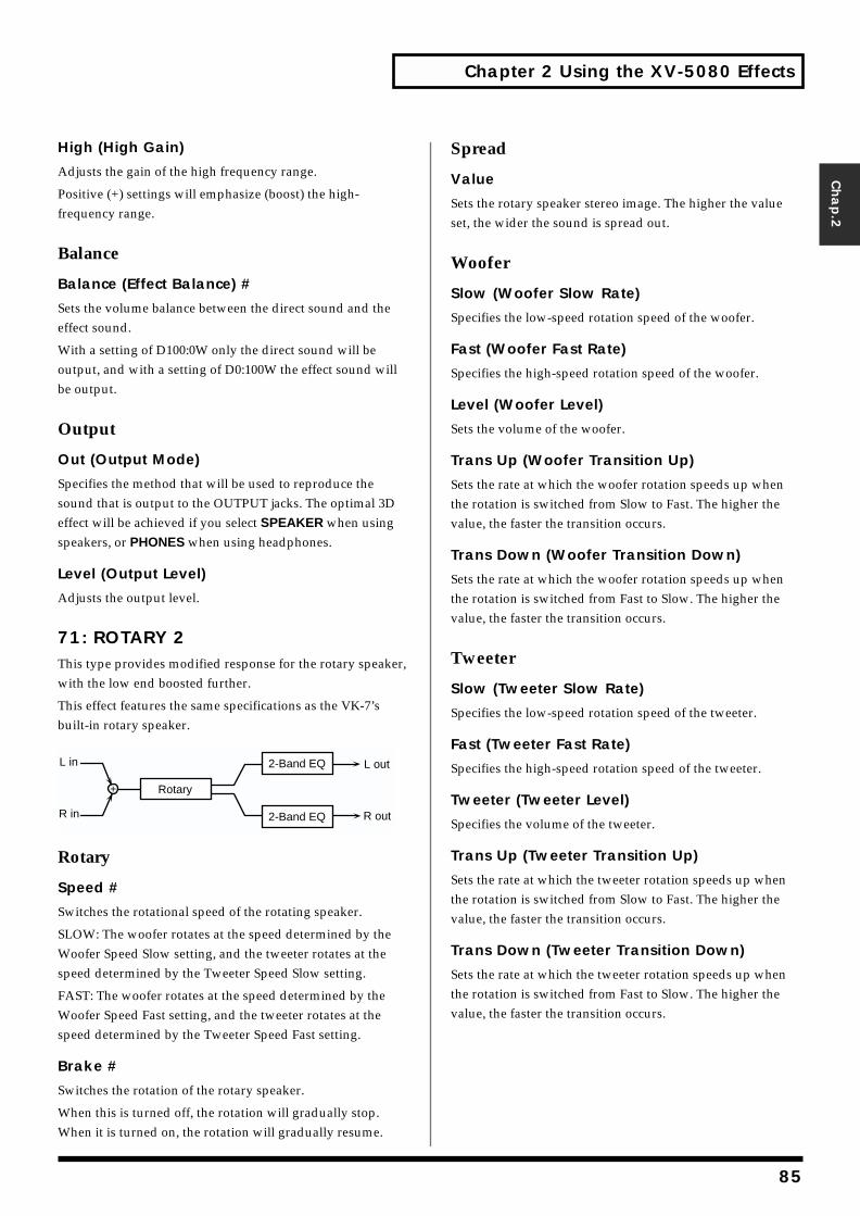
Chapter 2 Using the XV-5080 Effects
Chap.2
High (High Gain)
Adjusts the gain of the high frequency range.
Positive (+) settings will emphasize (boost) the high-frequency range.
Balance
Balance (Effect Balance) #
Sets the volume balance between the direct sound and the effect sound.
With a setting of D100:0W only the direct sound will be output, and with a setting of D0:100W the effect sound will be output.
Output
Out (Output Mode)
Specifies the method that will be used to reproduce the sound that is output to the OUTPUT jacks. The optimal 3D effect will be achieved if you select SPEAKER when using speakers, or PHONES when using headphones.
Level (Output Level)
Adjusts the output level.
71: ROTARY 2This type provides modified response for the rotary speaker, with the low end boosted further.
This effect features the same specifications as the VK-7’s built-in rotary speaker.fig.02-071m.e
Rotary
Speed #
Switches the rotational speed of the rotating speaker.
SLOW: The woofer rotates at the speed determined by the Woofer Speed Slow setting, and the tweeter rotates at the speed determined by the Tweeter Speed Slow setting.
FAST: The woofer rotates at the speed determined by the Woofer Speed Fast setting, and the tweeter rotates at the speed determined by the Tweeter Speed Fast setting.
Brake #
Switches the rotation of the rotary speaker.
When this is turned off, the rotation will gradually stop. When it is turned on, the rotation will gradually resume.
Spread
Value
Sets the rotary speaker stereo image. The higher the value set, the wider the sound is spread out.
Woofer
Slow (Woofer Slow Rate)
Specifies the low-speed rotation speed of the woofer.
Fast (Woofer Fast Rate)
Specifies the high-speed rotation speed of the woofer.
Level (Woofer Level)
Sets the volume of the woofer.
Trans Up (Woofer Transition Up)
Sets the rate at which the woofer rotation speeds up when the rotation is switched from Slow to Fast. The higher the value, the faster the transition occurs.
Trans Down (Woofer Transition Down)
Sets the rate at which the woofer rotation speeds up when the rotation is switched from Fast to Slow. The higher the value, the faster the transition occurs.
Tweeter
Slow (Tweeter Slow Rate)
Specifies the low-speed rotation speed of the tweeter.
Fast (Tweeter Fast Rate)
Specifies the high-speed rotation speed of the tweeter.
Tweeter (Tweeter Level)
Specifies the volume of the tweeter.
Trans Up (Tweeter Transition Up)
Sets the rate at which the tweeter rotation speeds up when the rotation is switched from Slow to Fast. The higher the value, the faster the transition occurs.
Trans Down (Tweeter Transition Down)
Sets the rate at which the tweeter rotation speeds up when the rotation is switched from Fast to Slow. The higher the value, the faster the transition occurs.
L out
R out
L in
R in
Rotary
2-Band EQ
2-Band EQ
85

Chapter 2 Using the XV-5080 Effects
EQ Gain
Low (Low Gain)
Adjusts the gain of the low frequency range.
Positive (+) settings will emphasize (boost) the low-frequency range.
High (High Gain)
Adjusts the gain of the high frequency range.
Positive (+) settings will emphasize (boost) the high-frequency range.
Output
Level (Output Level) #
Adjusts the output level.
72: ROTARY MULTIThis connects Overdrive/Distortion (ODDS), 3-band equalizer (EQ), and Rotary (RT) effects in series.fig.02-072m.e
Sequence
OD/Dist (Overdrive/Distortion Switch)
Turns the Overdrive or Distortion on/off.
Amp Sim (Amp Simulator Switch)
Turns the Amp Simulator on/off.
3 Band EQ (3 Band EQ Switch)
Turns the 3 Band EQ on/off.
Rotary (Rotary Switch)
Turns the Rotary on/off.
Overdrive/Distortion
Type
Selects whether to use Overdrive or Distortion.
Drive #
Adjusts the degree of distortion. The volume will change together with the degree of distortion.
Tone
Adjusts the sound quality of the Overdrive/Distortion effect.
Level
Adjusts the Overdrive/Distortion output level.
Amp Simulator
Type (Amp Type)
Selects the type of guitar amp.
EQ Gain
Low (EQ Low Gain)
Adjusts the low-range gain of the equalizer.
Mid (EQ Mid Gain)
Adjusts the gain of the area specified by the EQ M Fq parameter and the EQ M Q parameter.
High (EQ High Gain)
Adjusts the high-range gain of the equalizer.
Mid
Mid Freq (EQ Mid Frequency)
Sets the center frequency for the equalizer mid-range.
Mid Q (EQ Mid Q)
Adjusts the width of the area centered at the EQ M Fq setting in which the gain will be affected. Higher values of Q will result in a narrower area being affected.
Rotary
Speed #
Simultaneously switch the rotational speed of both the low-range and the high-range rotors.
Slow: Slow down the rotation to the specified speeds (RT L Slow parameter/RT H Slow parameter values).
Fast: Speed up the rotation to the specified speeds (RT L Fast parameter/RT H Fast parameter values).
Separation
Adjusts the spatial spread of the rotary sound.
Woofer
Slow (Low Frequency Slow Rate)
Adjusts the speed of the low-range rotor for the slow-speed setting.
L out
Pan
R out
L in
R in
Overdrive/Distortion
Rotary
3-Band EQAmpSimulator
86
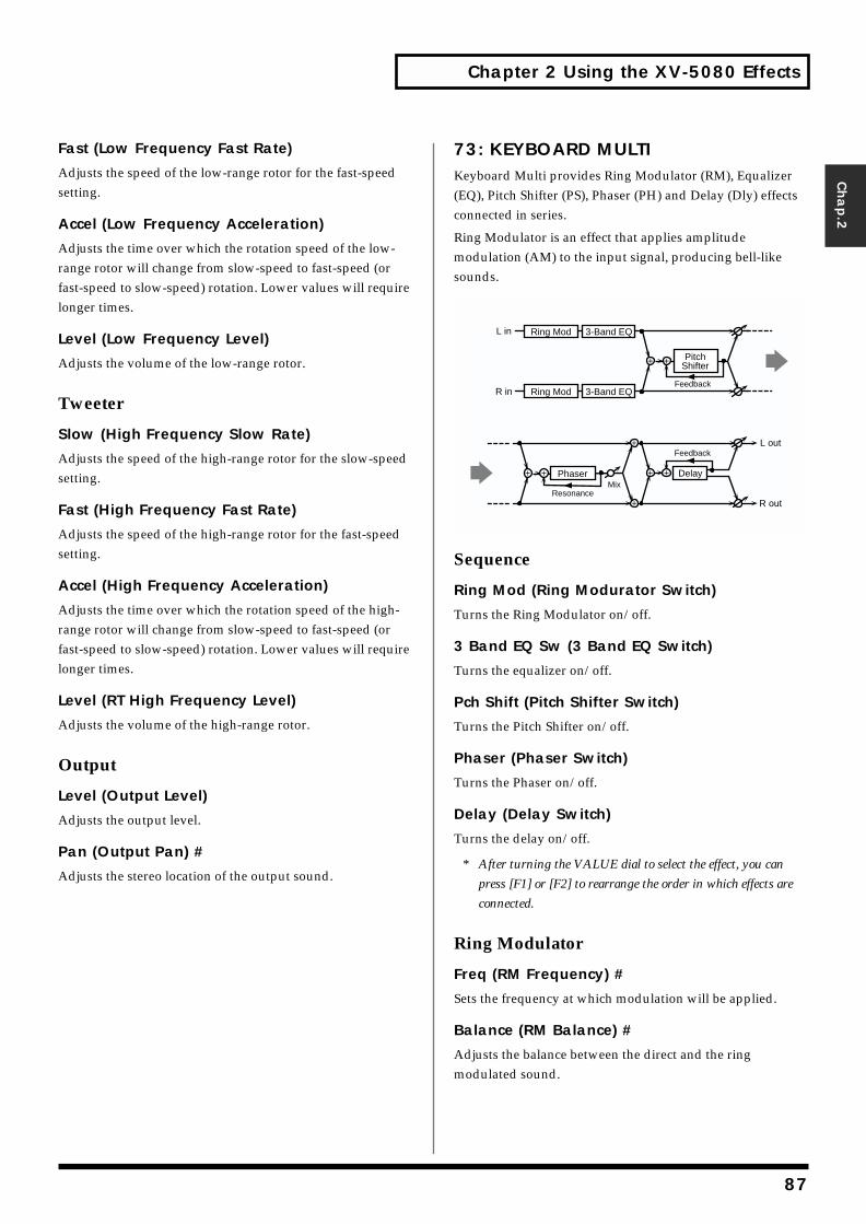
Chapter 2 Using the XV-5080 Effects
Chap.2
Fast (Low Frequency Fast Rate)
Adjusts the speed of the low-range rotor for the fast-speed setting.
Accel (Low Frequency Acceleration)
Adjusts the time over which the rotation speed of the low-range rotor will change from slow-speed to fast-speed (or fast-speed to slow-speed) rotation. Lower values will require longer times.
Level (Low Frequency Level)
Adjusts the volume of the low-range rotor.
Tweeter
Slow (High Frequency Slow Rate)
Adjusts the speed of the high-range rotor for the slow-speed setting.
Fast (High Frequency Fast Rate)
Adjusts the speed of the high-range rotor for the fast-speed setting.
Accel (High Frequency Acceleration)
Adjusts the time over which the rotation speed of the high-range rotor will change from slow-speed to fast-speed (or fast-speed to slow-speed) rotation. Lower values will require longer times.
Level (RT High Frequency Level)
Adjusts the volume of the high-range rotor.
Output
Level (Output Level)
Adjusts the output level.
Pan (Output Pan) #
Adjusts the stereo location of the output sound.
73: KEYBOARD MULTIKeyboard Multi provides Ring Modulator (RM), Equalizer (EQ), Pitch Shifter (PS), Phaser (PH) and Delay (Dly) effects connected in series.
Ring Modulator is an effect that applies amplitude modulation (AM) to the input signal, producing bell-like sounds.fig.02-073m.e
Sequence
Ring Mod (Ring Modurator Switch)
Turns the Ring Modulator on/off.
3 Band EQ Sw (3 Band EQ Switch)
Turns the equalizer on/off.
Pch Shift (Pitch Shifter Switch)
Turns the Pitch Shifter on/off.
Phaser (Phaser Switch)
Turns the Phaser on/off.
Delay (Delay Switch)
Turns the delay on/off.
* After turning the VALUE dial to select the effect, you can
press [F1] or [F2] to rearrange the order in which effects are
connected.
Ring Modulator
Freq (RM Frequency) #
Sets the frequency at which modulation will be applied.
Balance (RM Balance) #
Adjusts the balance between the direct and the ring modulated sound.
Feedback
PitchShifter
L in
R in
Ring Mod
Ring Mod
3-Band EQ
3-Band EQ
Feedback
Delay
L out
R outResonance
MixPhaser
87
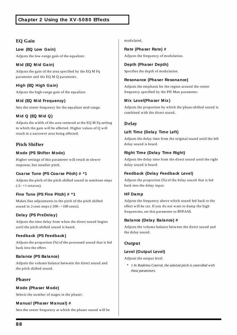
Chapter 2 Using the XV-5080 Effects
EQ Gain
Low (EQ Low Gain)
Adjusts the low-range gain of the equalizer.
Mid (EQ Mid Gain)
Adjusts the gain of the area specified by the EQ M Fq parameter and the EQ M Q parameter.
High (EQ High Gain)
Adjusts the high-range gain of the equalizer.
Mid (EQ Mid Frequency)
Sets the center frequency for the equalizer mid-range.
Mid Q (EQ Mid Q)
Adjusts the width of the area centered at the EQ M Fq setting in which the gain will be affected. Higher values of Q will result in a narrower area being affected.
Pitch Shifter
Mode (PS Shifter Mode)
Higher settings of this parameter will result in slower response, but steadier pitch.
Coarse Tune (PS Coarse Pitch) # *1
Adjusts the pitch of the pitch-shifted sound in semitone steps (-2– +1 octaves).
Fine Tune (PS Fine Pitch) # *1
Makes fine adjustments to the pitch of the pitch shifted sound in 2-cent steps (-100– +100 cents).
Delay (PS PreDelay)
Adjusts the time delay from when the direct sound begins until the pitch-shifted sound is heard.
Feedback (PS Feedback)
Adjusts the proportion (%) of the processed sound that is fed back into the effect.
Balance (PS Balance)
Adjusts the volume balance between the direct sound and the pitch shifted sound.
Phaser
Mode (Phaser Mode)
Selects the number of stages in the phaser.
Manual (Phaser Manual) #
Sets the center frequency at which the phaser sound will be
modulated.
Rate (Phaser Rate) #
Adjusts the frequency of modulation.
Depth (Phaser Depth)
Specifies the depth of modulation.
Resonance (Phaser Resonance)
Adjusts the emphasis for the region around the center frequency specified by the PH Man parameter.
Mix Level(Phaser Mix)
Adjusts the proportion by which the phase-shifted sound is combined with the direct sound.
Delay
Left Time (Delay Time Left)
Adjusts the delay time from the original sound until the left delay sound is heard.
Right Time (Delay Time Right)
Adjusts the delay time from the direct sound until the right delay sound is heard.
Feedback (Delay Feedback Level)
Adjusts the proportion (%) of the delay sound that is fed back into the delay input.
HF Damp
Adjusts the frequency above which sound fed back to the effect will be cut. If you do not want to damp the high frequencies, set this parameter to BYPASS.
Balance (Delay Balance) #
Adjusts the volume balance between the direct sound and the delay sound.
Output
Level (Output Level)
Adjusts the output level.
* 1 In Realtime Control, the selected pitch is controlled with
these parameters.
88
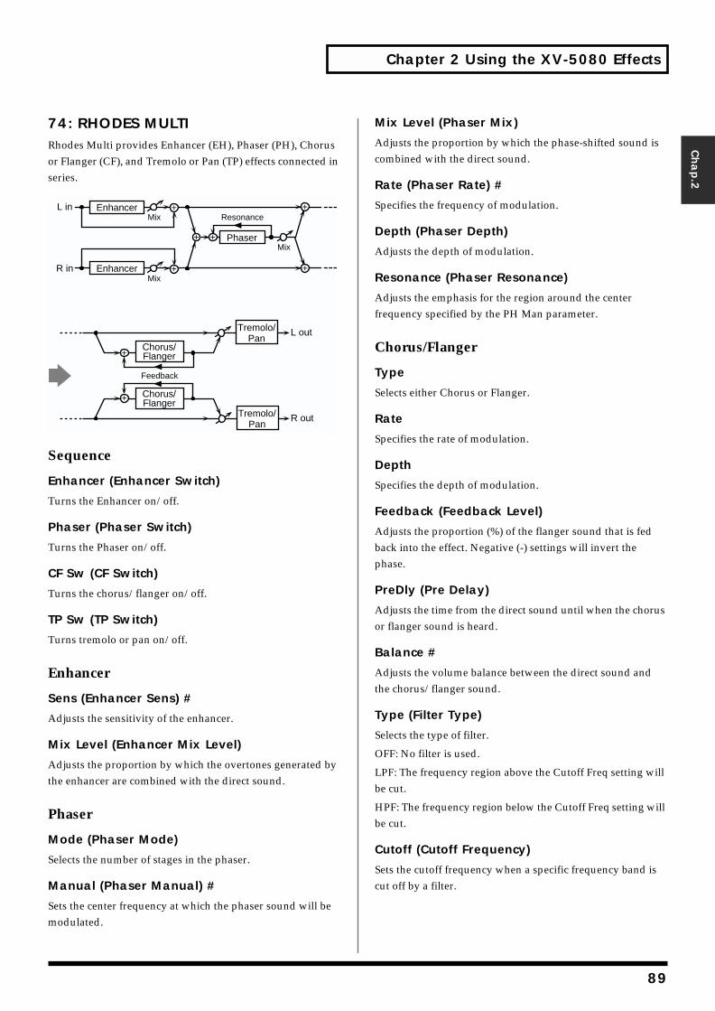
Chapter 2 Using the XV-5080 Effects
Chap.2
74: RHODES MULTIRhodes Multi provides Enhancer (EH), Phaser (PH), Chorus or Flanger (CF), and Tremolo or Pan (TP) effects connected in series.fig.02-074m.e
Sequence
Enhancer (Enhancer Switch)
Turns the Enhancer on/off.
Phaser (Phaser Switch)
Turns the Phaser on/off.
CF Sw (CF Switch)
Turns the chorus/flanger on/off.
TP Sw (TP Switch)
Turns tremolo or pan on/off.
Enhancer
Sens (Enhancer Sens) #
Adjusts the sensitivity of the enhancer.
Mix Level (Enhancer Mix Level)
Adjusts the proportion by which the overtones generated by the enhancer are combined with the direct sound.
Phaser
Mode (Phaser Mode)
Selects the number of stages in the phaser.
Manual (Phaser Manual) #
Sets the center frequency at which the phaser sound will be modulated.
Mix Level (Phaser Mix)
Adjusts the proportion by which the phase-shifted sound is combined with the direct sound.
Rate (Phaser Rate) #
Specifies the frequency of modulation.
Depth (Phaser Depth)
Adjusts the depth of modulation.
Resonance (Phaser Resonance)
Adjusts the emphasis for the region around the center frequency specified by the PH Man parameter.
Chorus/Flanger
Type
Selects either Chorus or Flanger.
Rate
Specifies the rate of modulation.
Depth
Specifies the depth of modulation.
Feedback (Feedback Level)
Adjusts the proportion (%) of the flanger sound that is fed back into the effect. Negative (-) settings will invert the phase.
PreDly (Pre Delay)
Adjusts the time from the direct sound until when the chorus or flanger sound is heard.
Balance #
Adjusts the volume balance between the direct sound and the chorus/flanger sound.
Type (Filter Type)
Selects the type of filter.
OFF: No filter is used.
LPF: The frequency region above the Cutoff Freq setting will be cut.
HPF: The frequency region below the Cutoff Freq setting will be cut.
Cutoff (Cutoff Frequency)
Sets the cutoff frequency when a specific frequency band is cut off by a filter.
Resonance
Phaser
L in
R in
Mix
Mix
Mix
Enhancer
Enhancer
R out
L out
Chorus/Flanger
Chorus/Flanger
Feedback
Tremolo/Pan
Tremolo/Pan
89
Chapter 2 Using the XV-5080 Effects
Tremolo/Pan
Type
Selects either Tremolo or Pan.
ModWave (Modulation Wave)
Selects the way in which tremolo or pan will be modulated.
Tri: The sound will be modulated like a triangle wave.
Sqr: The sound will be modulated like a square wave.
Sin: The sound will be modulated like a sine wave.
Saw1,2: The sound will be modulated like a sawtooth wave.
The teeth in SAW1 and SAW2 point at opposite directions.
Rate (Modulation Rate) #
Specifies the rate of modulation.
Depth (Modulation Depth) #
Specifies the depth of modulation.
Output
Level (Output Level)
Adjusts the output level.
75: JD MULTIThis allows the Distortion (DS), Phaser (PH), Spectrum (SP), and Enhancer (EH) effects to be connected in series in any desired order.fig.02-075m.e
SEQUENCE
Dist (Distortion Switch)
Turns the Distortion on/off.
Phaser (Phaser Switch)
Turns the phaser on/off.
Spectrum (Spectrum Switch)
Turns the Spectrum on/off.
Enhancer Sw (Enhancer Switch)
Turns the Enhancer on/off.
* After turning the VALUE dial to select the effect, you can hold
down [SHIFT] and press [F1] or [F2] to rearrange the order in
which effects are connected.
Distortion
Type (Distortion Type)
Specifies the type of the distortion.
MELLOW DRIVE: A soft, mellow distortion; somewhat dark sounding.
OVERDRIVE: The classic sound of an overdriven tube amp.
CRY DRIVE: Distortion with a high-frequency boost.
MELLOW DIST: Sounds like the distortion you’d get from a really big amp.
LIGHT DIST: A distortion with an intense, brilliant feel.
FAT DIST: Boosted lows and highs gives this one a thick, fat sound.
FUZZ DIST: Like FAT DIST, but with even more distortion.
Drive (Distortion Drive) #
Adjusts the degree of distortion.
Level (Distortion Level)
Sets the distortion output level.
Phaser
Manual (Phaser Manual) #
Specifies the center frequency at which the sound is modulated.
Mix Level #
Specifies the volume of the phase-shifted sound, relative to the direct sound.
Rate (Phaser Rate) #
Specifies the frequency of modulation.
Depth (Phaser Depth) #
Adjusts the depth of modulation.
Resonance (Phaser Resonance) #
Adjusts the amount of feedback for the phaser. Higher settings will give the sound a stronger character.
Spectrum
Band Width
Specifies the range of all bands in which the level will be
L out
R out
L in
R in
Distortion
Spectrum Enhancer
Phaser
90
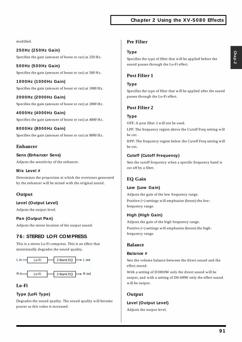
Chapter 2 Using the XV-5080 Effects
Chap.2
modified.
250Hz (250Hz Gain)
Specifies the gain (amount of boost or cut) at 250 Hz.
500Hz (500Hz Gain)
Specifies the gain (amount of boost or cut) at 500 Hz.
1000Hz (1000Hz Gain)
Specifies the gain (amount of boost or cut) at 1000 Hz.
2000Hz (2000Hz Gain)
Specifies the gain (amount of boost or cut) at 2000 Hz.
4000Hz (4000Hz Gain)
Specifies the gain (amount of boost or cut) at 4000 Hz.
8000Hz (8000Hz Gain)
Specifies the gain (amount of boost or cut) at 8000 Hz.
Enhancer
Sens (Enhancer Sens)
Adjusts the sensitivity of the enhancer.
Mix Level #
Determines the proportion at which the overtones generated by the enhancer will be mixed with the original sound.
Output
Level (Output Level)
Adjusts the output level.
Pan (Output Pan)
Adjusts the stereo location of the output sound.
76: STEREO LOFI COMPRESSThis is a stereo Lo-Fi compress. This is an effect that intentionally degrades the sound quality.fig.02-076m.e
Lo-Fi
Type (LoFi Type)
Degrades the sound quality. The sound quality will become poorer as this value is increased.
Pre Filter
Type
Specifies the type of filter that will be applied before the sound passes through the Lo-Fi effect.
Post Filter 1
Type
Specifies the type of filter that will be applied after the sound passes through the Lo-Fi effect.
Post Filter 2
Type
OFF: A post filter 2 will not be used.
LPF: The frequency region above the Cutoff Freq setting will be cut.
HPF: The frequency region below the Cutoff Freq setting will be cut.
Cutoff (Cutoff Frequency)
Sets the cutoff frequency when a specific frequency band is cut off by a filter.
EQ Gain
Low (Low Gain)
Adjusts the gain of the low frequency range.
Positive (+) settings will emphasize (boost) the low-frequency range.
High (High Gain)
Adjusts the gain of the high frequency range.
Positive (+) settings will emphasize (boost) the high-frequency range.
Balance
Balance #
Sets the volume balance between the direct sound and the effect sound.
With a setting of D100:0W only the direct sound will be output, and with a setting of D0:100W only the effect sound will be output.
Output
Level (Output Level)
Adjusts the output level.
L in
R in
L out
R out
Lo-Fi
2-Band EQ
2-Band EQ
Lo-Fi
91
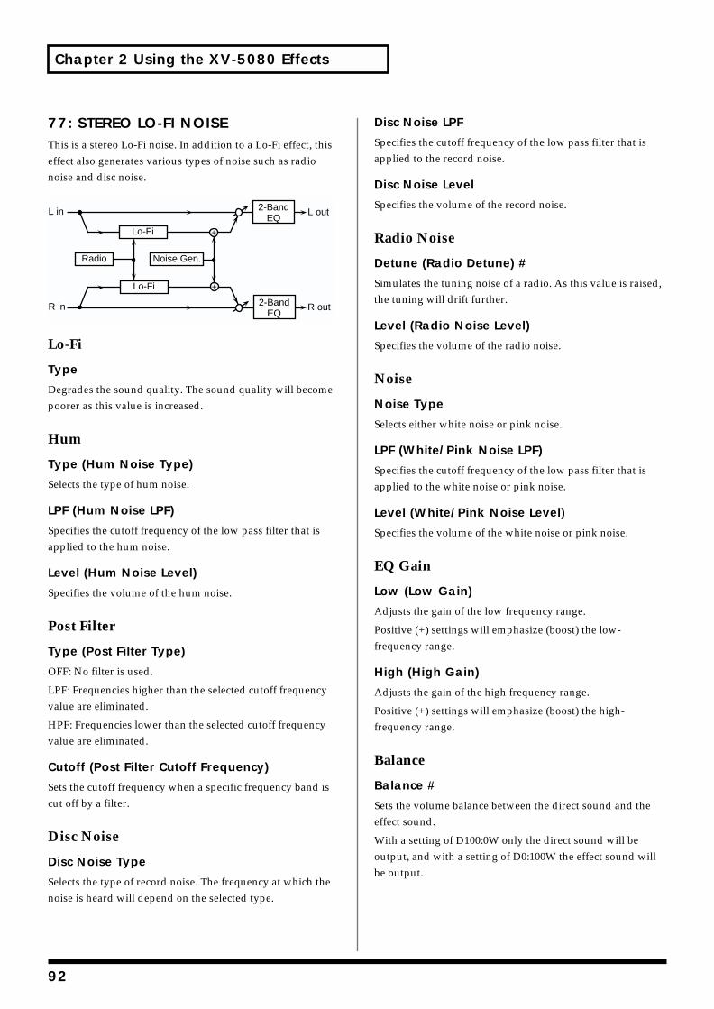
Chapter 2 Using the XV-5080 Effects
77: STEREO LO-FI NOISEThis is a stereo Lo-Fi noise. In addition to a Lo-Fi effect, this effect also generates various types of noise such as radio noise and disc noise.fig.02-077m.e
Lo-Fi
Type
Degrades the sound quality. The sound quality will become poorer as this value is increased.
Hum
Type (Hum Noise Type)
Selects the type of hum noise.
LPF (Hum Noise LPF)
Specifies the cutoff frequency of the low pass filter that is applied to the hum noise.
Level (Hum Noise Level)
Specifies the volume of the hum noise.
Post Filter
Type (Post Filter Type)
OFF: No filter is used.
LPF: Frequencies higher than the selected cutoff frequency value are eliminated.
HPF: Frequencies lower than the selected cutoff frequency value are eliminated.
Cutoff (Post Filter Cutoff Frequency)
Sets the cutoff frequency when a specific frequency band is cut off by a filter.
Disc Noise
Disc Noise Type
Selects the type of record noise. The frequency at which the noise is heard will depend on the selected type.
Disc Noise LPF
Specifies the cutoff frequency of the low pass filter that is applied to the record noise.
Disc Noise Level
Specifies the volume of the record noise.
Radio Noise
Detune (Radio Detune) #
Simulates the tuning noise of a radio. As this value is raised, the tuning will drift further.
Level (Radio Noise Level)
Specifies the volume of the radio noise.
Noise
Noise Type
Selects either white noise or pink noise.
LPF (White/Pink Noise LPF)
Specifies the cutoff frequency of the low pass filter that is applied to the white noise or pink noise.
Level (White/Pink Noise Level)
Specifies the volume of the white noise or pink noise.
EQ Gain
Low (Low Gain)
Adjusts the gain of the low frequency range.
Positive (+) settings will emphasize (boost) the low-frequency range.
High (High Gain)
Adjusts the gain of the high frequency range.
Positive (+) settings will emphasize (boost) the high-frequency range.
Balance
Balance #
Sets the volume balance between the direct sound and the effect sound.
With a setting of D100:0W only the direct sound will be output, and with a setting of D0:100W the effect sound will be output.
R in R out
L in L out
Lo-Fi
Lo-Fi
2-BandEQ
2-BandEQ
Noise Gen.Radio
92
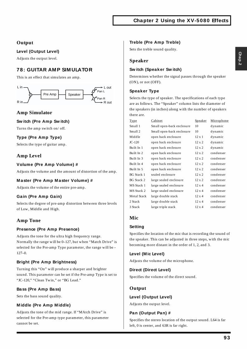
Chapter 2 Using the XV-5080 Effects
Chap.2
Output
Level (Output Level)
Adjusts the output level.
78: GUITAR AMP SIMULATORThis is an effect that simulates an amp.fig.02-078m.e
Amp Simulator
Switch (Pre Amp Switch)
Turns the amp switch on/off.
Type (Pre Amp Type)
Selects the type of guitar amp.
Amp Level
Volume (Pre Amp Volume) #
Adjusts the volume and the amount of distortion of the amp.
Master (Pre Amp Master Volume) #
Adjusts the volume of the entire pre-amp.
Gain (Pre Amp Gain)
Selects the degree of pre-amp distortion between three levels of Low, Middle and High.
Amp Tone
Presence (Pre Amp Presence)
Adjusts the tone for the ultra high frequency range. Normally the range will be 0–127, but when “Match Drive” is selected for the Pre-amp Type parameter, the range will be -127–0.
Bright (Pre Amp Brightness)
Turning this “On” will produce a sharper and brighter sound. This parameter can be set if the Pre-amp Type is set to “JC-120,” “Clean Twin,” or “BG Lead.”
Bass (Pre Amp Bass)
Sets the bass sound quality.
Middle (Pre Amp Middle)
Adjusts the tone of the mid range. If “MAtch Drive” is selected for the Pre-amp type parameter, this parameter cannot be set.
Treble (Pre Amp Treble)
Sets the treble sound quality.
Speaker
Switch (Speaker Switch)
Determines whether the signal passes through the speaker (ON), or not (OFF).
Speaker Type
Selects the type of speaker. The specifications of each type are as follows. The “Speaker” column lists the diameter of the speakers (in inches) along with the number of speakers there are.
Type Cabinet Speaker Microphone
Small 1 Small open-back enclosure 10 dynamic
Small 2 Small open-back enclosure 10 dynamic
Middle open back enclosure 12 x 1 dynamic
JC-120 open back enclosure 12 x 2 dynamic
Built In 1 open back enclosure 12 x 2 dynamic
Built In 2 open back enclosure 12 x 2 condenser
Built In 3 open back enclosure 12 x 2 condenser
Built In 4 open back enclosure 12 x 2 condenser
Built In 5 open back enclosure 12 x 2 condenser
BG Stack 1 sealed enclosure 12 x 2 condenser
BG Stack 2 large sealed enclosure 12 x 2 condenser
MS Stack 1 large sealed enclosure 12 x 4 condenser
MS Stack 2 large sealed enclosure 12 x 4 condenser
Metal Stack large double stack 12 x 4 condenser
2 Stack large double stack 12 x 4 condenser
3 Stack large triple stack 12 x 4 condenser
Mic
Setting
Specifies the location of the mic that is recording the sound of the speaker. This can be adjusted in three steps, with the mic becoming more distant in the order of 1, 2, and 3.
Level (Mic Level)
Adjusts the volume of the microphone.
Direct (Direct Level)
Specifies the volume of the direct sound.
Output
Level (Output Level)
Adjusts the output level.
Pan (Output Pan) #
Specifies the stereo location of the output sound. L64 is far left, 0 is center, and 63R is far right.
L in
R in
L out
R outPan R
Pan LPre Amp Speaker
93
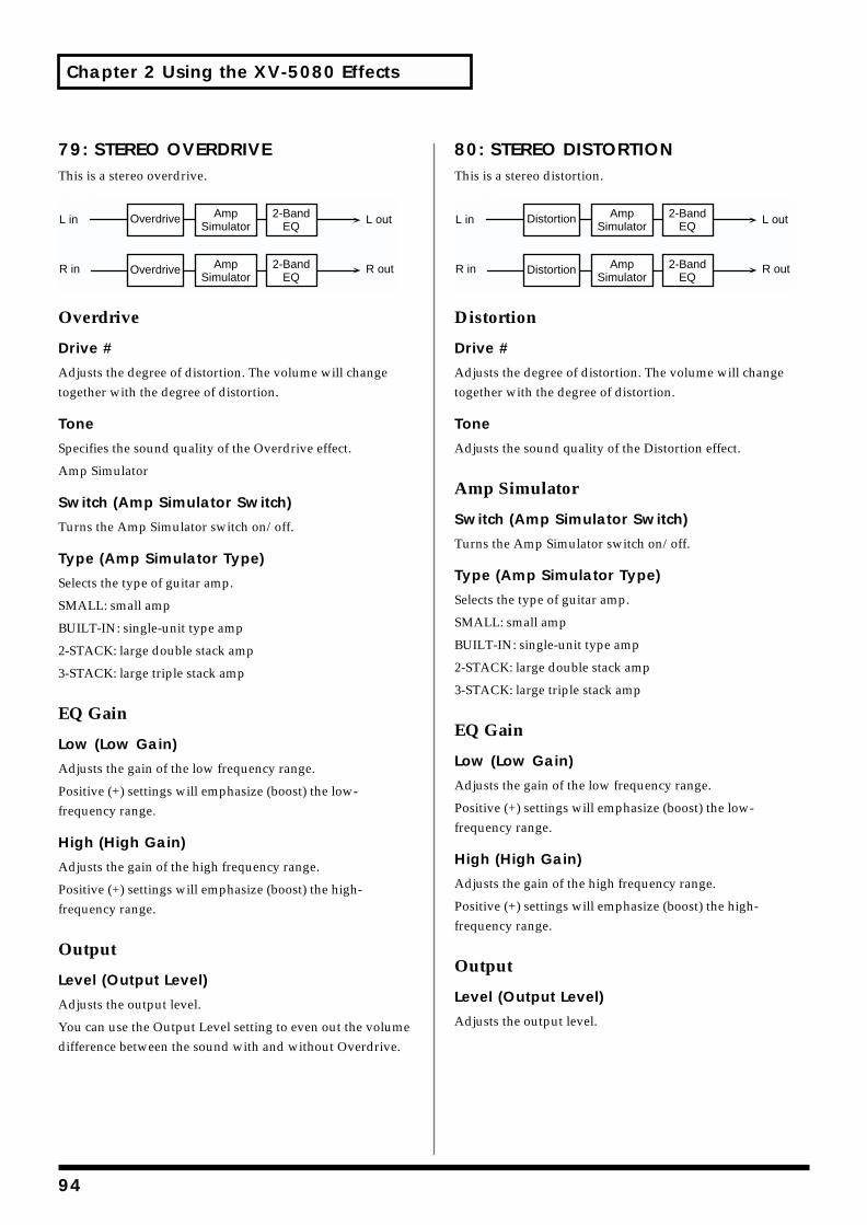
Chapter 2 Using the XV-5080 Effects
79: STEREO OVERDRIVEThis is a stereo overdrive.fig.02-079m.e
Overdrive
Drive #
Adjusts the degree of distortion. The volume will change together with the degree of distortion.
Tone
Specifies the sound quality of the Overdrive effect.
Amp Simulator
Switch (Amp Simulator Switch)
Turns the Amp Simulator switch on/off.
Type (Amp Simulator Type)
Selects the type of guitar amp.
SMALL: small amp
BUILT-IN: single-unit type amp
2-STACK: large double stack amp
3-STACK: large triple stack amp
EQ Gain
Low (Low Gain)
Adjusts the gain of the low frequency range.
Positive (+) settings will emphasize (boost) the low-frequency range.
High (High Gain)
Adjusts the gain of the high frequency range.
Positive (+) settings will emphasize (boost) the high-frequency range.
Output
Level (Output Level)
Adjusts the output level.
You can use the Output Level setting to even out the volume difference between the sound with and without Overdrive.
80: STEREO DISTORTIONThis is a stereo distortion.fig.02-080m.e
Distortion
Drive #
Adjusts the degree of distortion. The volume will change together with the degree of distortion.
Tone
Adjusts the sound quality of the Distortion effect.
Amp Simulator
Switch (Amp Simulator Switch)
Turns the Amp Simulator switch on/off.
Type (Amp Simulator Type)
Selects the type of guitar amp.
SMALL: small amp
BUILT-IN: single-unit type amp
2-STACK: large double stack amp
3-STACK: large triple stack amp
EQ Gain
Low (Low Gain)
Adjusts the gain of the low frequency range.
Positive (+) settings will emphasize (boost) the low-frequency range.
High (High Gain)
Adjusts the gain of the high frequency range.
Positive (+) settings will emphasize (boost) the high-frequency range.
Output
Level (Output Level)
Adjusts the output level.fig.02-080ms.e
L in
R in
L out
R out
AmpSimulator
2-BandEQ
Overdrive
AmpSimulator
2-BandEQ
Overdrive
L in
R in
L out
R out
AmpSimulator
2-BandEQ
Distortion
AmpSimulator
2-BandEQ
Distortion
94
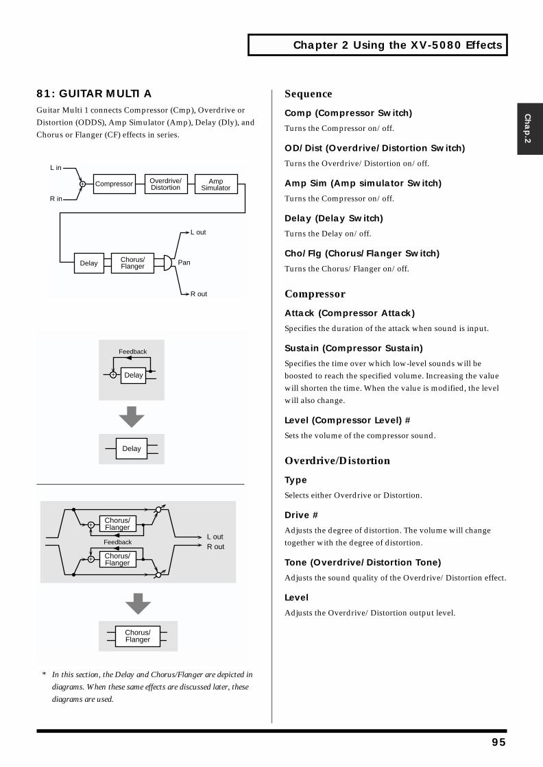
Chapter 2 Using the XV-5080 Effects
Chap.2
81: GUITAR MULTI AGuitar Multi 1 connects Compressor (Cmp), Overdrive or Distortion (ODDS), Amp Simulator (Amp), Delay (Dly), and Chorus or Flanger (CF) effects in series.
* In this section, the Delay and Chorus/Flanger are depicted in
diagrams. When these same effects are discussed later, these
diagrams are used.
Sequence
Comp (Compressor Switch)
Turns the Compressor on/off.
OD/Dist (Overdrive/Distortion Switch)
Turns the Overdrive/Distortion on/off.
Amp Sim (Amp simulator Switch)
Turns the Compressor on/off.
Delay (Delay Switch)
Turns the Delay on/off.
Cho/Flg (Chorus/Flanger Switch)
Turns the Chorus/Flanger on/off.
Compressor
Attack (Compressor Attack)
Specifies the duration of the attack when sound is input.
Sustain (Compressor Sustain)
Specifies the time over which low-level sounds will be boosted to reach the specified volume. Increasing the value will shorten the time. When the value is modified, the level will also change.
Level (Compressor Level) #
Sets the volume of the compressor sound.
Overdrive/Distortion
Type
Selects either Overdrive or Distortion.
Drive #
Adjusts the degree of distortion. The volume will change together with the degree of distortion.
Tone (Overdrive/Distortion Tone)
Adjusts the sound quality of the Overdrive/Distortion effect.
Level
Adjusts the Overdrive/Distortion output level.
L in
R in
Compressor AmpSimulator
Overdrive/Distortion
R out
L out
PanDelay Chorus/Flanger
R outL out
Chorus/Flanger
Chorus/Flanger
Feedback
Delay
Feedback
Delay
Chorus/Flanger
95
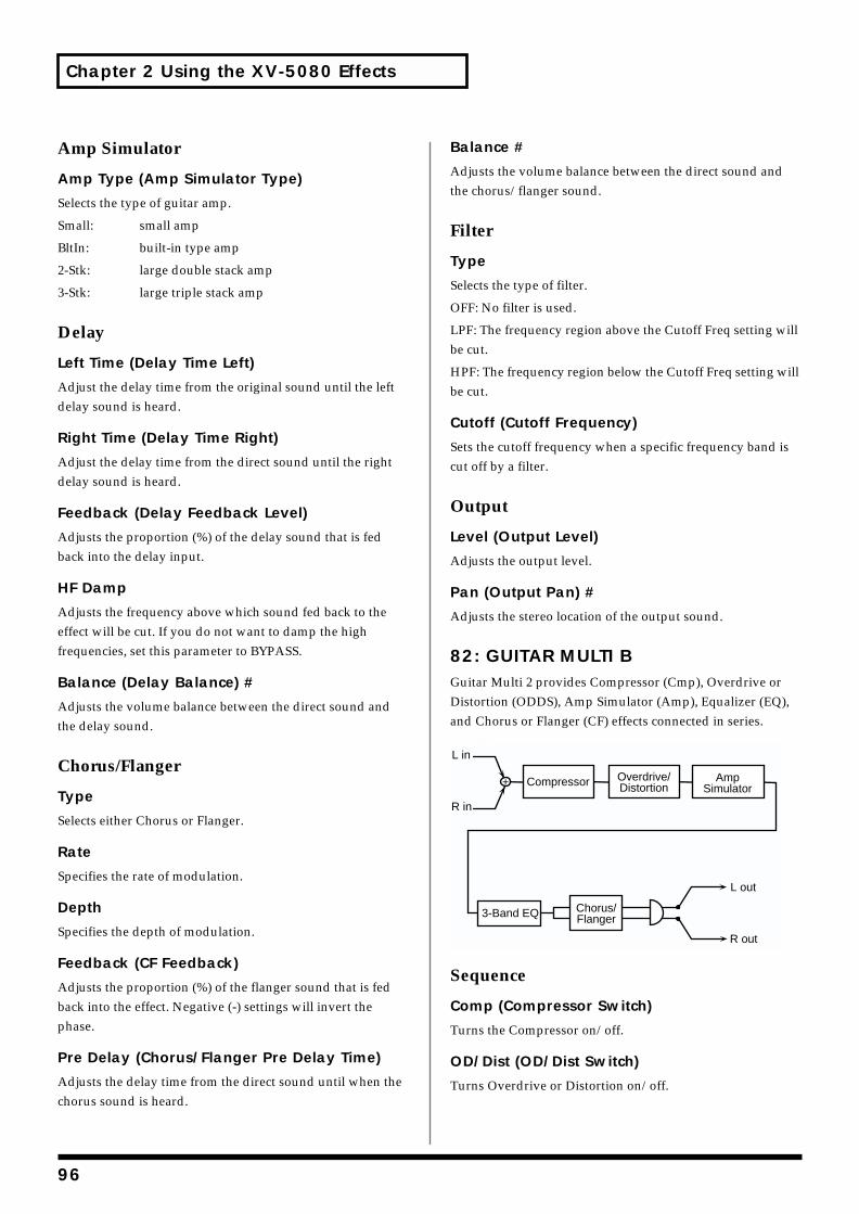
Chapter 2 Using the XV-5080 Effects
Amp Simulator
Amp Type (Amp Simulator Type)
Selects the type of guitar amp.
Small: small amp
BltIn: built-in type amp
2-Stk: large double stack amp
3-Stk: large triple stack amp
Delay
Left Time (Delay Time Left)
Adjust the delay time from the original sound until the left delay sound is heard.
Right Time (Delay Time Right)
Adjust the delay time from the direct sound until the right delay sound is heard.
Feedback (Delay Feedback Level)
Adjusts the proportion (%) of the delay sound that is fed back into the delay input.
HF Damp
Adjusts the frequency above which sound fed back to the effect will be cut. If you do not want to damp the high frequencies, set this parameter to BYPASS.
Balance (Delay Balance) #
Adjusts the volume balance between the direct sound and the delay sound.
Chorus/Flanger
Type
Selects either Chorus or Flanger.
Rate
Specifies the rate of modulation.
Depth
Specifies the depth of modulation.
Feedback (CF Feedback)
Adjusts the proportion (%) of the flanger sound that is fed back into the effect. Negative (-) settings will invert the phase.
Pre Delay (Chorus/Flanger Pre Delay Time)
Adjusts the delay time from the direct sound until when the chorus sound is heard.
Balance #
Adjusts the volume balance between the direct sound and the chorus/flanger sound.
Filter
Type
Selects the type of filter.
OFF: No filter is used.
LPF: The frequency region above the Cutoff Freq setting will be cut.
HPF: The frequency region below the Cutoff Freq setting will be cut.
Cutoff (Cutoff Frequency)
Sets the cutoff frequency when a specific frequency band is cut off by a filter.
Output
Level (Output Level)
Adjusts the output level.
Pan (Output Pan) #
Adjusts the stereo location of the output sound.
82: GUITAR MULTI BGuitar Multi 2 provides Compressor (Cmp), Overdrive or Distortion (ODDS), Amp Simulator (Amp), Equalizer (EQ), and Chorus or Flanger (CF) effects connected in series.fig.02-082m.e
Sequence
Comp (Compressor Switch)
Turns the Compressor on/off.
OD/Dist (OD/Dist Switch)
Turns Overdrive or Distortion on/off.
L in
R in
Compressor AmpSimulator
Overdrive/Distortion
3-Band EQ
L out
R out
Chorus/Flanger
96
Chapter 2 Using the XV-5080 Effects
Chap.2
Amp Sim (Amp Simulator Switch)
Turns the Amp Simulator on/off.
3 Band EQ (3 Band EQ Switch)
Turns the equalizer on/off.
Cho/Flg (Chorus/Flanger Switch)
Turns the chorus/flanger on/off.
Compressor
Attack (Compressor Attack)
Specifies the duration of the attack when sound is input.
Sustain (Compressor Sustain)
Specifies the time over which low-level sounds will be boosted to reach the specified volume. Increasing the value will shorten the time. When the value is modified, the level will also change.
Level (Compressor Level) #
Sets the volume of the compressor sound.
Overdrive/Distortion
Type
Selects either Overdrive or Distortion.
Drive #
Adjusts the degree of distortion. The volume will change together with the degree of distortion.
Tone (Overdrive/Distortion Tone)
Adjusts the sound quality of the Overdrive/Distortion effect.
Level
Sets the volume of the overdrive sound.
Amp Simulator
Type (Amp Simulator Type)
Selects the type of guitar amp.
Small: small amp
BltIn: built-in type amp
2-Stk: large double stack amp
3-Stk: large triple stack amp
EQ Gain
Low (EQ Low Gain)
Adjusts the low-range gain of the equalizer.
Mid (EQ Mid Gain)
Adjusts the gain of the area specified by the EQ M Fq parameter and the EQ M Q parameter.
High (EQ High Gain)
Adjusts the high-range gain of the equalizer.
Mid
Mid (EQ Mid Frequency)
Sets the center frequency for the equalizer mid-range.
Mid Q (EQ Mid Q)
Adjusts the width of the area centered at the EQ M Fq setting in which the gain will be affected. Higher values of Q will result in a narrower area being affected.
Chorus/Flanger
Type
Selects either Chorus or Flanger.
Rate
Sets the modulation speed for the chorus or flanger.
Depth
Sets the modulation depth for the chorus or flanger.
Feedback
Adjusts the proportion (%) of the flanger sound that is fed back into the effect. Negative (-) settings will invert the phase.
Pre Delay (Chorus/Flanger Pre Delay Time)
Adjusts the delay time from the direct sound until when the chorus sound is heard.
Balance #
Adjusts the volume balance between the direct sound and the chorus/flanger sound.
Filter
Type (Filter Type)
Selects the type of filter.
OFF: No filter is used.
LPF: The frequency region above the Cutoff Freq setting will be cut.
HPF: The frequency region below the Cutoff Freq setting will be cut.
97
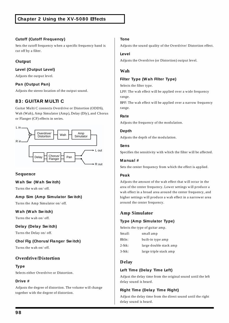
Chapter 2 Using the XV-5080 Effects
Cutoff (Cutoff Frequency)
Sets the cutoff frequency when a specific frequency band is cut off by a filter.
Output
Level (Output Level)
Adjusts the output level.
Pan (Output Pan)
Adjusts the stereo location of the output sound.
83: GUITAR MULTI CGuitar Multi C connects Overdrive or Distortion (ODDS), Wah (Wah), Amp Simulator (Amp), Delay (Dly), and Chorus or Flanger (CF) effects in series.fig.02-083m.e
Sequence
Wah Sw (Wah Switch)
Turns the wah on/off.
Amp Sim (Amp Simulator Switch)
Turns the Amp Simulator on/off.
Wah (Wah Switch)
Turns the wah on/off.
Delay (Delay Switch)
Turns the Delay on/off.
Cho/Flg (Chorus/Flanger Switch)
Turns the wah on/off.
Overdrive/Distortion
Type
Selects either Overdrive or Distortion.
Drive #
Adjusts the degree of distortion. The volume will change together with the degree of distortion.
Tone
Adjusts the sound quality of the Overdrive/Distortion effect.
Level
Adjusts the Overdrive (or Distortion) output level.
Wah
Filter Type (Wah FIlter Type)
Selects the filter type.
LPF: The wah effect will be applied over a wide frequency range.
BPF: The wah effect will be applied over a narrow frequency range.
Rate
Adjusts the frequency of the modulation.
Depth
Adjusts the depth of the modulation.
Sens
Specifies the sensitivity with which the filter will be affected.
Manual #
Sets the center frequency from which the effect is applied.
Peak
Adjusts the amount of the wah effect that will occur in the area of the center frequency. Lower settings will produce a wah effect in a broad area around the center frequency, and higher settings will produce a wah effect in a narrower area around the center frequency.
Amp Simulator
Type (Amp Simulator Type)
Selects the type of guitar amp.
Small: small amp
BltIn: built-in type amp
2-Stk: large double stack amp
3-Stk: large triple stack amp
Delay
Left Time (Delay Time Left)
Adjust the delay time from the original sound until the left delay sound is heard.
Right Time (Delay Time Right)
Adjust the delay time from the direct sound until the right delay sound is heard.
L out
R out
L in
R in
Overdrive/Distortion
AmpSimulator
Delay Chorus/Flanger
Pan
Wah
98
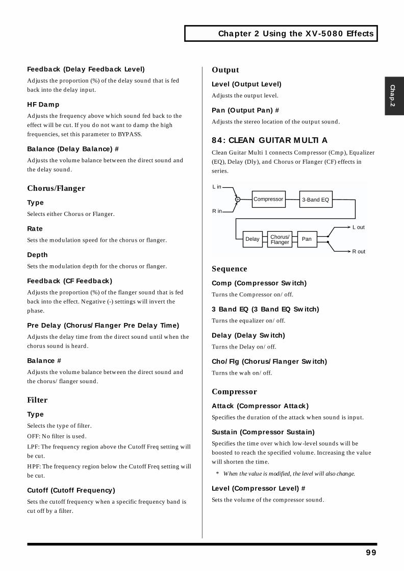
Chapter 2 Using the XV-5080 Effects
Chap.2
Feedback (Delay Feedback Level)
Adjusts the proportion (%) of the delay sound that is fed back into the delay input.
HF Damp
Adjusts the frequency above which sound fed back to the effect will be cut. If you do not want to damp the high frequencies, set this parameter to BYPASS.
Balance (Delay Balance) #
Adjusts the volume balance between the direct sound and the delay sound.
Chorus/Flanger
Type
Selects either Chorus or Flanger.
Rate
Sets the modulation speed for the chorus or flanger.
Depth
Sets the modulation depth for the chorus or flanger.
Feedback (CF Feedback)
Adjusts the proportion (%) of the flanger sound that is fed back into the effect. Negative (-) settings will invert the phase.
Pre Delay (Chorus/Flanger Pre Delay Time)
Adjusts the delay time from the direct sound until when the chorus sound is heard.
Balance #
Adjusts the volume balance between the direct sound and the chorus/flanger sound.
Filter
Type
Selects the type of filter.
OFF: No filter is used.
LPF: The frequency region above the Cutoff Freq setting will be cut.
HPF: The frequency region below the Cutoff Freq setting will be cut.
Cutoff (Cutoff Frequency)
Sets the cutoff frequency when a specific frequency band is cut off by a filter.
Output
Level (Output Level)
Adjusts the output level.
Pan (Output Pan) #
Adjusts the stereo location of the output sound.
84: CLEAN GUITAR MULTI AClean Guitar Multi 1 connects Compressor (Cmp), Equalizer (EQ), Delay (Dly), and Chorus or Flanger (CF) effects in series.fig.02-084m.e
Sequence
Comp (Compressor Switch)
Turns the Compressor on/off.
3 Band EQ (3 Band EQ Switch)
Turns the equalizer on/off.
Delay (Delay Switch)
Turns the Delay on/off.
Cho/Flg (Chorus/Flanger Switch)
Turns the wah on/off.
Compressor
Attack (Compressor Attack)
Specifies the duration of the attack when sound is input.
Sustain (Compressor Sustain)
Specifies the time over which low-level sounds will be boosted to reach the specified volume. Increasing the value will shorten the time.
* When the value is modified, the level will also change.
Level (Compressor Level) #
Sets the volume of the compressor sound.
L out
R out
L in
R in
Compressor
Delay Chorus/Flanger
Pan
3-Band EQ
99
Chapter 2 Using the XV-5080 Effects
EQ Gain
Low (EQ Low Gain)
Adjusts the low-range gain of the equalizer.
EQ M Gain (EQ Mid Gain)
Adjusts the gain of the area specified by the EQ M Fq parameter and the EQ M Q parameter.
High (EQ High Gain)
Adjusts the high-range gain of the equalizer.
Mid
Mid Freq (EQ Mid Frequency)
Sets the center frequency for the equalizer mid-range.
Mid Q (EQ Mid Q)
Adjusts the width of the area centered at the EQ M Fq setting in which the gain will be affected. Higher values of Q will result in a narrower area being affected.
Delay
Left Time (Delay Time Left)
Adjust the delay time from the original sound until the left delay sound is heard.
Right Time (Delay Time Right)
Adjust the delay time from the direct sound until the right delay sound is heard.
Feedback (Delay Feedback Level)
Adjusts the proportion (%) of the delay sound that is fed back into the delay input.
HF Dump (Delay HF Damp)
Adjusts the frequency above which delayed sound fed back to the delay input will be cut. If you do not want the sound to be cut, select BYPASS.
Balance (Delay Balance) #
Adjusts the volume balance between the direct sound and the delay sound.
Chorus/Flanger
Type
Selects either Chorus or Flanger.
Rate
Sets the modulation speed for the chorus or flanger.
Depth
Sets the modulation depth for the chorus or flanger.
Feedback (CF Feedback)
Adjusts the proportion (%) of the flanger sound that is fed back into the effect. Negative (-) settings will invert the phase.
Pre Dly (Chorus/Flanger Pre Delay Time)
Adjusts the delay time from the direct sound until when the chorus sound is heard.
Balance #
Adjusts the volume balance between the direct sound and the chorus/flanger sound.
Filter
Type
Selects the type of filter.
OFF: No filter is used.
LPF: The frequency region above the Cutoff Freq setting will be cut.
HPF: The frequency region below the Cutoff Freq setting will be cut.
Cutoff (Cutoff Frequency)
Sets the cutoff frequency when a specific frequency band is cut off by a filter.
Output
Level (Output Level)
Adjusts the output level.
Pan (Output Pan)
Adjusts the stereo location of the output sound.
100
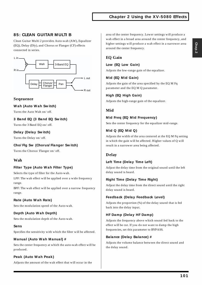
Chapter 2 Using the XV-5080 Effects
Chap.2
85: CLEAN GUITAR MULTI BClean Guitar Multi 2 provides Auto-wah (AW), Equalizer (EQ), Delay (Dly), and Chorus or Flanger (CF) effects connected in series.fig.02-085m.e
Seqeuence
Wah (Auto Wah Switch)
Turns the Auto Wah on/off.
3 Band EQ (3 Band EQ Switch)
Turns the 3 Band EQ on/off.
Delay (Delay Switch)
Turns the Delay on/off.
Cho/Flg Sw (Chorus/Flanger Switch)
Turns the Chorus/Flanger on/off.
Wah
Filter Type (Auto Wah Filter Type)
Selects the type of filter for the Auto-wah.
LPF: The wah effect will be applied over a wide frequency range.
BPF: The wah effect will be applied over a narrow frequency range.
Rate (Auto Wah Rate)
Sets the modulation speed of the Auto-wah.
Depth (Auto Wah Depth)
Sets the modulation depth of the Auto-wah.
Sens
Specifies the sensitivity with which the filter will be affected.
Manual (Auto Wah Manual) #
Sets the center frequency at which the auto-wah effect will be produced.
Peak (Auto Wah Peak)
Adjusts the amount of the wah effect that will occur in the
area of the center frequency. Lower settings will produce a wah effect in a broad area around the center frequency, and higher settings will produce a wah effect in a narrower area around the center frequency.
EQ Gain
Low (EQ Low Gain)
Adjusts the low-range gain of the equalizer.
Mid (EQ Mid Gain)
Adjusts the gain of the area specified by the EQ M Fq parameter and the EQ M Q parameter.
High (EQ High Gain)
Adjusts the high-range gain of the equalizer.
Mid
Mid Freq (EQ Mid Frequency)
Sets the center frequency for the equalizer mid-range.
Mid Q (EQ Mid Q)
Adjusts the width of the area centered at the EQ M Fq setting in which the gain will be affected. Higher values of Q will result in a narrower area being affected.
Delay
Left Time (Delay Time Left)
Adjust the delay time from the original sound until the left delay sound is heard.
Right Time (Delay Time Right)
Adjust the delay time from the direct sound until the right delay sound is heard.
Feedback (Delay Feedback Level)
Adjusts the proportion (%) of the delay sound that is fed back into the delay input.
HF Damp (Delay HF Damp)
Adjusts the frequency above which sound fed back to the effect will be cut. If you do not want to damp the high frequencies, set this parameter to BYPASS.
Balance (Delay Balance) #
Adjusts the volume balance between the direct sound and the delay sound.
L out
R out
L in
R in
Wah
Delay Chorus/Flanger
Pan
3-Band EQ
101
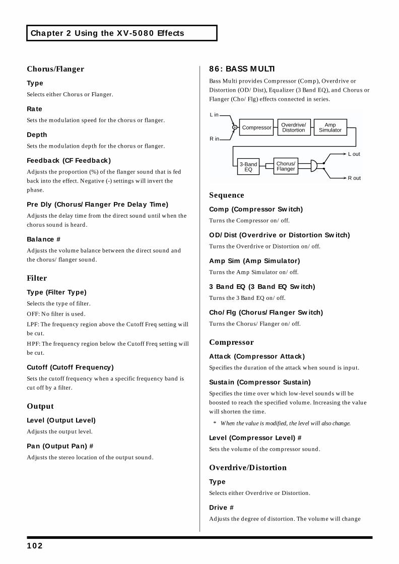
Chapter 2 Using the XV-5080 Effects
Chorus/Flanger
Type
Selects either Chorus or Flanger.
Rate
Sets the modulation speed for the chorus or flanger.
Depth
Sets the modulation depth for the chorus or flanger.
Feedback (CF Feedback)
Adjusts the proportion (%) of the flanger sound that is fed back into the effect. Negative (-) settings will invert the phase.
Pre Dly (Chorus/Flanger Pre Delay Time)
Adjusts the delay time from the direct sound until when the chorus sound is heard.
Balance #
Adjusts the volume balance between the direct sound and the chorus/flanger sound.
Filter
Type (Filter Type)
Selects the type of filter.
OFF: No filter is used.
LPF: The frequency region above the Cutoff Freq setting will be cut.
HPF: The frequency region below the Cutoff Freq setting will be cut.
Cutoff (Cutoff Frequency)
Sets the cutoff frequency when a specific frequency band is cut off by a filter.
Output
Level (Output Level)
Adjusts the output level.
Pan (Output Pan) #
Adjusts the stereo location of the output sound.
86: BASS MULTIBass Multi provides Compressor (Comp), Overdrive or Distortion (OD/Dist), Equalizer (3 Band EQ), and Chorus or Flanger (Cho/Flg) effects connected in series.fig.02-086m.e
Sequence
Comp (Compressor Switch)
Turns the Compressor on/off.
OD/Dist (Overdrive or Distortion Switch)
Turns the Overdrive or Distortion on/off.
Amp Sim (Amp Simulator)
Turns the Amp Simulator on/off.
3 Band EQ (3 Band EQ Switch)
Turns the 3 Band EQ on/off.
Cho/Flg (Chorus/Flanger Switch)
Turns the Chorus/Flanger on/off.
Compressor
Attack (Compressor Attack)
Specifies the duration of the attack when sound is input.
Sustain (Compressor Sustain)
Specifies the time over which low-level sounds will be boosted to reach the specified volume. Increasing the value will shorten the time.
* When the value is modified, the level will also change.
Level (Compressor Level) #
Sets the volume of the compressor sound.
Overdrive/Distortion
Type
Selects either Overdrive or Distortion.
Drive #
Adjusts the degree of distortion. The volume will change
L out
R out
L in
R in
Compressor
3-BandEQ
Overdrive/Distortion
AmpSimulator
Chorus/Flanger
102
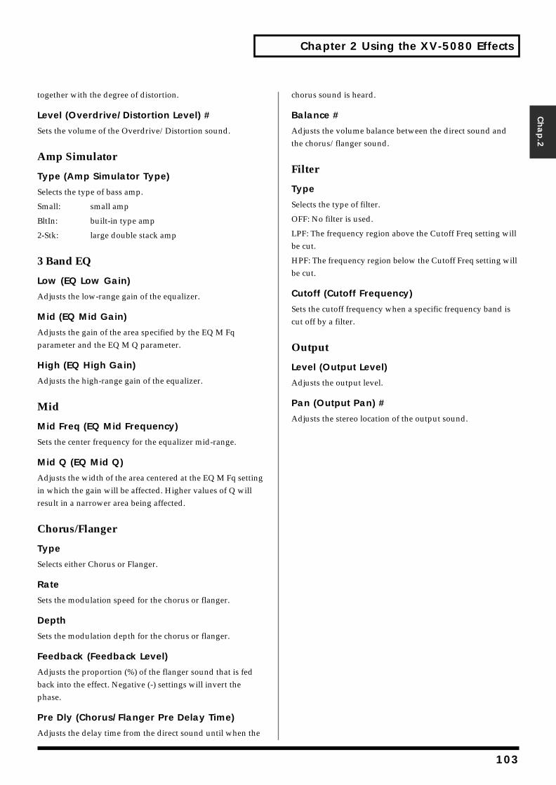
Chapter 2 Using the XV-5080 Effects
Chap.2
together with the degree of distortion.
Level (Overdrive/Distortion Level) #
Sets the volume of the Overdrive/Distortion sound.
Amp Simulator
Type (Amp Simulator Type)
Selects the type of bass amp.
Small: small amp
BltIn: built-in type amp
2-Stk: large double stack amp
3 Band EQ
Low (EQ Low Gain)
Adjusts the low-range gain of the equalizer.
Mid (EQ Mid Gain)
Adjusts the gain of the area specified by the EQ M Fq parameter and the EQ M Q parameter.
High (EQ High Gain)
Adjusts the high-range gain of the equalizer.
Mid
Mid Freq (EQ Mid Frequency)
Sets the center frequency for the equalizer mid-range.
Mid Q (EQ Mid Q)
Adjusts the width of the area centered at the EQ M Fq setting in which the gain will be affected. Higher values of Q will result in a narrower area being affected.
Chorus/Flanger
Type
Selects either Chorus or Flanger.
Rate
Sets the modulation speed for the chorus or flanger.
Depth
Sets the modulation depth for the chorus or flanger.
Feedback (Feedback Level)
Adjusts the proportion (%) of the flanger sound that is fed back into the effect. Negative (-) settings will invert the phase.
Pre Dly (Chorus/Flanger Pre Delay Time)
Adjusts the delay time from the direct sound until when the
chorus sound is heard.
Balance #
Adjusts the volume balance between the direct sound and the chorus/flanger sound.
Filter
Type
Selects the type of filter.
OFF: No filter is used.
LPF: The frequency region above the Cutoff Freq setting will be cut.
HPF: The frequency region below the Cutoff Freq setting will be cut.
Cutoff (Cutoff Frequency)
Sets the cutoff frequency when a specific frequency band is cut off by a filter.
Output
Level (Output Level)
Adjusts the output level.
Pan (Output Pan) #
Adjusts the stereo location of the output sound.
103
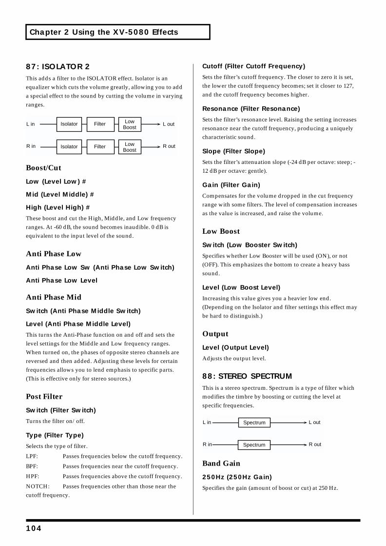
Chapter 2 Using the XV-5080 Effects
87: ISOLATOR 2This adds a filter to the ISOLATOR effect. Isolator is an equalizer which cuts the volume greatly, allowing you to add a special effect to the sound by cutting the volume in varying ranges.fig.02-087m.e
Boost/Cut
Low (Level Low) #
Mid (Level Middle) #
High (Level High) #
These boost and cut the High, Middle, and Low frequency ranges. At -60 dB, the sound becomes inaudible. 0 dB is equivalent to the input level of the sound.
Anti Phase Low
Anti Phase Low Sw (Anti Phase Low Switch)
Anti Phase Low Level
Anti Phase Mid
Switch (Anti Phase Middle Switch)
Level (Anti Phase Middle Level)
This turns the Anti-Phase function on and off and sets the level settings for the Middle and Low frequency ranges. When turned on, the phases of opposite stereo channels are reversed and then added. Adjusting these levels for certain frequencies allows you to lend emphasis to specific parts. (This is effective only for stereo sources.)
Post Filter
Switch (Filter Switch)
Turns the filter on/off.
Type (Filter Type)
Selects the type of filter.
LPF: Passes frequencies below the cutoff frequency.
BPF: Passes frequencies near the cutoff frequency.
HPF: Passes frequencies above the cutoff frequency.
NOTCH: Passes frequencies other than those near the cutoff frequency.
Cutoff (Filter Cutoff Frequency)
Sets the filter’s cutoff frequency. The closer to zero it is set, the lower the cutoff frequency becomes; set it closer to 127, and the cutoff frequency becomes higher.
Resonance (Filter Resonance)
Sets the filter’s resonance level. Raising the setting increases resonance near the cutoff frequency, producing a uniquely characteristic sound.
Slope (Filter Slope)
Sets the filter’s attenuation slope (-24 dB per octave: steep; -12 dB per octave: gentle).
Gain (Filter Gain)
Compensates for the volume dropped in the cut frequency range with some filters. The level of compensation increases as the value is increased, and raise the volume.
Low Boost
Switch (Low Booster Switch)
Specifies whether Low Booster will be used (ON), or not (OFF). This emphasizes the bottom to create a heavy bass sound.
Level (Low Boost Level)
Increasing this value gives you a heavier low end. (Depending on the Isolator and filter settings this effect may be hard to distinguish.)
Output
Level (Output Level)
Adjusts the output level.
88: STEREO SPECTRUMThis is a stereo spectrum. Spectrum is a type of filter which modifies the timbre by boosting or cutting the level at specific frequencies.fig.02-088m.e
Band Gain
250Hz (250Hz Gain)
Specifies the gain (amount of boost or cut) at 250 Hz.
L in
R in
L out
R out
LowBoost
Isolator Filter
LowBoost
Isolator Filter
L in
R in
L out
R out
Spectrum
Spectrum
104
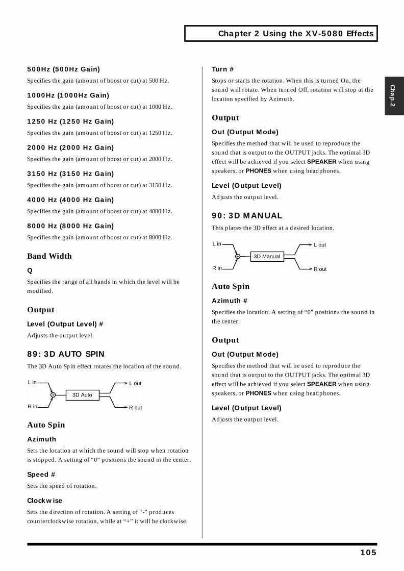
Chapter 2 Using the XV-5080 Effects
Chap.2
500Hz (500Hz Gain)
Specifies the gain (amount of boost or cut) at 500 Hz.
1000Hz (1000Hz Gain)
Specifies the gain (amount of boost or cut) at 1000 Hz.
1250 Hz (1250 Hz Gain)
Specifies the gain (amount of boost or cut) at 1250 Hz.
2000 Hz (2000 Hz Gain)
Specifies the gain (amount of boost or cut) at 2000 Hz.
3150 Hz (3150 Hz Gain)
Specifies the gain (amount of boost or cut) at 3150 Hz.
4000 Hz (4000 Hz Gain)
Specifies the gain (amount of boost or cut) at 4000 Hz.
8000 Hz (8000 Hz Gain)
Specifies the gain (amount of boost or cut) at 8000 Hz.
Band Width
Q
Specifies the range of all bands in which the level will be modified.
Output
Level (Output Level) #
Adjusts the output level.
89: 3D AUTO SPINThe 3D Auto Spin effect rotates the location of the sound.fig.02-089m.e
Auto Spin
Azimuth
Sets the location at which the sound will stop when rotation is stopped. A setting of “0” positions the sound in the center.
Speed #
Sets the speed of rotation.
Clockwise
Sets the direction of rotation. A setting of “-” produces counterclockwise rotation, while at “+” it will be clockwise.
Turn #
Stops or starts the rotation. When this is turned On, the sound will rotate. When turned Off, rotation will stop at the location specified by Azimuth.
Output
Out (Output Mode)
Specifies the method that will be used to reproduce the sound that is output to the OUTPUT jacks. The optimal 3D effect will be achieved if you select SPEAKER when using speakers, or PHONES when using headphones.
Level (Output Level)
Adjusts the output level.
90: 3D MANUALThis places the 3D effect at a desired location.fig.02-090m.e
Auto Spin
Azimuth #
Specifies the location. A setting of “0” positions the sound in the center.
Output
Out (Output Mode)
Specifies the method that will be used to reproduce the sound that is output to the OUTPUT jacks. The optimal 3D effect will be achieved if you select SPEAKER when using speakers, or PHONES when using headphones.
Level (Output Level)
Adjusts the output level.
L out
R out
L in
R in
3D Auto
L out
R out
L in
R in
3D Manual
105
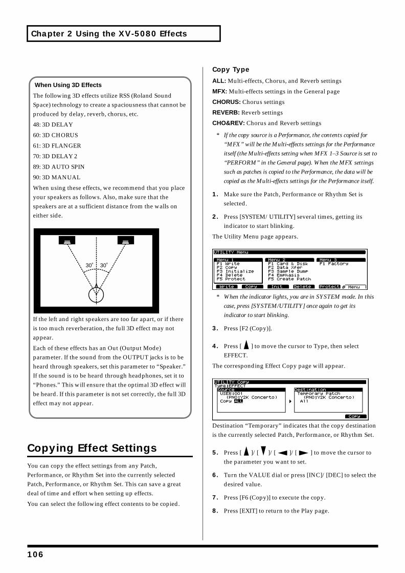
Chapter 2 Using the XV-5080 Effects
Copying Effect SettingsYou can copy the effect settings from any Patch, Performance, or Rhythm Set into the currently selected Patch, Performance, or Rhythm Set. This can save a great deal of time and effort when setting up effects.
You can select the following effect contents to be copied.
Copy Type
ALL: Multi-effects, Chorus, and Reverb settings
MFX: Multi-effects settings in the General page
CHORUS: Chorus settings
REVERB: Reverb settings
CHO&REV: Chorus and Reverb settings
* If the copy source is a Performance, the contents copied for
“MFX” will be the Multi-effects settings for the Performance
itself (the Multi-effects setting when MFX 1–3 Source is set to
“PERFORM” in the General page). When the MFX settings
such as patches is copied to the Performance, the data will be
copied as the Multi-effects settings for the Performance itself.
1. Make sure the Patch, Performance or Rhythm Set is selected.
2. Press [SYSTEM/UTILITY] several times, getting its indicator to start blinking.
The Utility Menu page appears.fig.02-032.e_70
* When the indicator lights, you are in SYSTEM mode. In this
case, press [SYSTEM/UTILITY] once again to get its
indicator to start blinking.
3. Press [F2 (Copy)].
4. Press [ ] to move the cursor to Type, then select EFFECT.
The corresponding Effect Copy page will appear.fig.02-033.e_70
Destination “Temporary” indicates that the copy destination is the currently selected Patch, Performance, or Rhythm Set.
5. Press [ ]/[ ]/[ ]/[ ] to move the cursor to the parameter you want to set.
6. Turn the VALUE dial or press [INC]/[DEC] to select the desired value.
7. Press [F6 (Copy)] to execute the copy.
8. Press [EXIT] to return to the Play page.
When Using 3D Effects
The following 3D effects utilize RSS (Roland Sound Space) technology to create a spaciousness that cannot be produced by delay, reverb, chorus, etc.
48: 3D DELAY
60: 3D CHORUS
61: 3D FLANGER
70: 3D DELAY 2
89: 3D AUTO SPIN
90: 3D MANUAL
When using these effects, we recommend that you place your speakers as follows. Also, make sure that the speakers are at a sufficient distance from the walls on either side.fig.02-031.e
If the left and right speakers are too far apart, or if there is too much reverberation, the full 3D effect may not appear.
Each of these effects has an Out (Output Mode) parameter. If the sound from the OUTPUT jacks is to be heard through speakers, set this parameter to “Speaker.” If the sound is to be heard through headphones, set it to “Phones.” This will ensure that the optimal 3D effect will be heard. If this parameter is not set correctly, the full 3D effect may not appear.
30˚ 30˚
106
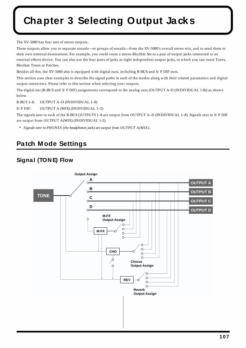
Chapter 3 Selecting Output Jacks
The XV-5080 has four sets of stereo outputs.
These outputs allow you to separate sounds—or groups of sounds—from the XV-5080’s overall stereo mix, and to send them to their own external destinations. For example, you could route a stereo Rhythm Set to a pair of output jacks connected to an external effects device. You can also use the four pairs of jacks as eight independent output jacks, to which you can route Tones, Rhythm Tones or Patches.
Besides all this, the XV-5080 also is equipped with digital outs, including R-BUS and S/P DIF outs.
This section uses clear examples to describe the signal paths in each of the modes along with their related parameters and digital output connectors. Please refer to this section when selecting your outputs.
The digital out (R-BUS and S/P DIF) assignments correspond to the analog outs (OUTPUT A-D (INDIVIDUAL 1-8)) as shown below.
R-BUS 1–8: OUTPUT A–D (INDIVIDUAL 1–8)
S/P DIF: OUTPUT A (MIX) (INDIVIDUAL 1–2)
The signals sent to each of the R-BUS OUTPUTS 1–8 are output from OUTPUT A–D (INDIVIDUAL 1–8). Signals sent to S/P DIF are output from OUTPUT A(MIX) (INDIVIDUAL 1-2).
* Signals sent to PHONES (the headphones jack) are output from OUTPUT A(MIX).
Patch Mode Settings
Signal (TONE) Flowfig.03-001.e
B
A
C
D
CHO
TONEOUTPUT B
OUTPUT C
OUTPUT D
REV
M-FX
Output Assign
M-FXOutput Assign
ChorusOutput Assign
ReverbOutput Assign
OUTPUT A
107
Chapter 3 Selecting Output Jacks
ParametersThe parameters related to Patch output settings are shown below.
PATCH Effects General page ([PATCH] - [F6 (Effects)] - [F1 (General)])This sets the output destination and level for the currently selected Tone, as well as its send level with respect to the Chorus and Reverb.
Tone Output Assign
Available Settings:
MFX: The Tone is sent into the Multi-effects. Its output destination is determined by the Multi-effects output settings.
OUTPUT A–D: The Tone is sent to one of the four output-jack stereo pairs, OUTPUTS A–D.
INDIV 1–8: The Tone is sent to the INDIVIDUAL OUTPUT jacks 1–8.
Tone Dry Send Level
Range: 0–127
Sets the level of the signal to be sent to the OUTPUT jacks, which is determined by Tone Output Assign.
Tone Chorus Send Level
Range: 0–127
Sets how much of the Tone is sent to the Chorus. Its final output destination is determined by the Chorus output setting.
Tone Reverb Send Level
Range: 0–127
Sets how much of the Tone is sent to the Reverb. Its final output destination is determined by the Reverb output setting.
MFX Dry Send Level
Range: 0–127
Determines the level of the Multi-effects processor’s output to the OUTPUT jacks.
MFX Chorus Send Level
Range: 0–127
Determines the level of the post-Multi-effects processor signal sent to Chorus. Its final output destination is determined by the Chorus output setting.
MFX Reverb Send Level
Range: 0–127
Determines the level of the post-Multi-effects processor signal sent to Reverb. Its final output destination is determined by the Reverb output setting.
Chorus Output Select
Specifies how the signal routed through Chorus will be output.
Available Settings:
MAIN: The Chorus output is sent only to the OUTPUT jacks.
REV: The Chorus output is sent only to the Reverb.
M+R: The Chorus output is sent to the OUTPUT jacks and to the Reverb.
Chorus Level
Range: 0–127
Determines the Chorus output level.
Reverb Level
Range: 0–127
Determines the Reverb output level.
MFX Output Assign
Range: A–D
Specifies the OUTPUT jacks to which the signal, after it has passed through the Multi-effects, is to be routed.
* As the Multi-effects are in stereo, settings for the
INDIVIDUAL OUTPUT jacks are unavailable.
Chorus Output Assign
Range: A–D
Selects the pair of OUTPUT jacks to which the Chorus unit’s stereo output is routed when Chorus Output Select is set to “MAIN” or “MAIN+R.” The output destination of the signal sent to Reverb follows the Reverb setting.
* As the internal effects processors are in stereo, settings for the
INDIVIDUAL OUTPUT jacks are unavailable.
Reverb Output Assign
Range: A–D
Selects the OUTPUT jacks to which the Reverb unit’s stereo output is routed.
* As the internal effects processors are in stereo, settings for the
INDIVIDUAL OUTPUT jacks are unavailable.
108
Chapter 3 Selecting Output Jacks
Chap.3
PATCH Common General #1 page ([PATCH] - [F1 (COMMON)] - [F1 (General)])
Common
Level (Patch Level)
Range: 0–127
Sets the volume of the Patch.
* You can specify the level for each Tone using the Tone Level
parameter (TVA; p. 143).
Pan (Patch Pan)
Range: L64–63R
Sets the stereo position of the Patch. L64 is far left, 0 is center, and 63R is far right.
* You can specify the pan setting for each Tone in a Patch using
the Tone Pan parameter (TVA; p. 143).
* While each of the Tones forming a Patch has its own Pan
position, the Patch Pan parameter shifts the individual stereo
locations of the Tones by the amount set for it.
Output Assign
Specifies the output destination for the Patch.
Available Settings:
MFX: The Patch is sent into the Multi-effects. Its output destination is determined by the Multi-effects output settings.
OUTPUT A–D: The Patch is sent to the selected pair of OUTPUT A–D jacks.
INDIV 1–8: The Patch is sent to the selected INDIVIDUAL OUTPUT 1–8 jack.
TONE: Each Tone in the Patch is sent to its programmed output destination.
SYSTEM Output page ([SYSTEM] - [F2 (OutP&EQ)])
Digital Interface
Master Freq (Master Frequency)
Range: 44.1/48 kHz
Selects the clock used for synchronizing the digital output.
Master Clock
Selects the master clock used for synchronizing the digital output.
Available Settings:
INTERNAL: The XV-5080 itself serves as the master.
R-BUS: Operation synchronized to the clock present on the R-BUS. The XV-5080 functions as the slave.
WORD CLOCK IN: Operation synchronized to the word clock. The XV-5080 functions as the slave.
* When operating as the slave, the XV-5080 is capable of
synchronizing to clocks running at 44.1 or 48 kHz. It cannot
sync to clocks at other frequencies.
Output Mix/Parallel
Mode
Available Settings:
MIX: All sounds—including those routed to OUTPUTs B/C or INDIVIDUAL 3–8—are mixed together and routed to the A (MIX) OUTPUT jacks. This setting allows you to quickly route everything through headphones when you are creating sounds, or to combine all of your sounds into two outputs when sending the XV-5080’s signal to a mixer that has only two channels.
When MIX is selected, sounds routed to the INDIVIDUAL OUTPUT 3/5/7 jacks are sent to the left A (MIX) OUTPUT jack, and sounds routed to the INDIVIDUAL OUTPUT 4/6/8 jacks are sent to the right A (MIX) OUTPUT jack.
PARALLEL: Sounds are routed to output jacks according to their output settings.
The XV-5080’s Master Level and Mix/Parallel settings are each established using a single global parameter.
SYSTEM General #1 page ([SYSTEM] - [F1 (General)])
Master
Level (Master Level)
Range: 0–127
Adjusts the volume of the entire XV-5080.
109
Chapter 3 Selecting Output Jacks
Example of Settings
Assigning Different Output Destinations for the Tones in a PatchIn this example, let’s suppose we have a Patch composed of four Tones, and we are outputting Tone 1 from the A OUTPUT jacks, Tone 2 from the B OUTPUT jacks, Tone 3 from the INDIVIDUAL 5 jack, and Tone 4 from the INDIVIDUAL 6 jack. The Chorus and Reverb are output from the B OUTPUT jacks.
First, set the output destination for each Tone.
1. Select the Patch you wish to set.
2. Press [F6 (Effects)].
3. Press [F1 (General)] to call up the PATCH Effects General page.
4. Use TONE SELECT [1]–[4] to select the Tone you wish to set up.
5. Press [ ]/[ ]/[ ]/[ ] to move the cursor to the parameter you wish to set, and rotate the VALUE dial, or press [INC] or [DEC] to set the value as follows.
Tone Output Tone Dry Tone Chorus Tone Reverb Assign Send Level Send Level Send Level
Tone 1 A 127 100 100Tone 2 B 127 100 100Tone 3 5 127 100 100Tone 4 6 127 100 100
The Chorus and Reverb send levels can be set to any value you wish other than 0.
6. Press [EXIT] to return to the PATCH PLAY page.
7. Press [F1 (Common)].
8. Press [ ]/[ ] to move the cursor to Output Assign.
9. Turn the VALUE dial or press [INC]/[DEC] to select “TONE.”
10. Press [EXIT] to return to the PATCH PLAY page.
Next, select the Chorus output destination and set its overall level.
11. Press [F6 (Effects)].
12. Press [ ]/[ ]/[ ]/[ ] to move the cursor to Chorus Output Assign.
13. Turn the VALUE dial or press [INC]/[DEC] to select “B.”
14. Press [ ]/[ ]/[ ]/[ ] to move the cursor to Chorus Level.
15. Turn the VALUE dial to select “100.”
16. Press [ ]/[ ] to move the cursor to Chorus Output Select.
17. Turn the VALUE dial or press [INC]/[DEC] to select “MAIN.”
Finally, select the Reverb output destination and set its overall level.
18. Press [ ]/[ ]/[ ]/[ ] to move the cursor to Reverb Output Assign.
19. Turn the VALUE dial or press [INC]/[DEC] to select “B.”
20. Press [ ]/[ ]/[ ]/[ ] to move the cursor to Reverb Level.
21. Turn the VALUE dial to select “100.”
22. Press [EXIT] to return to the PATCH PLAY page.
110
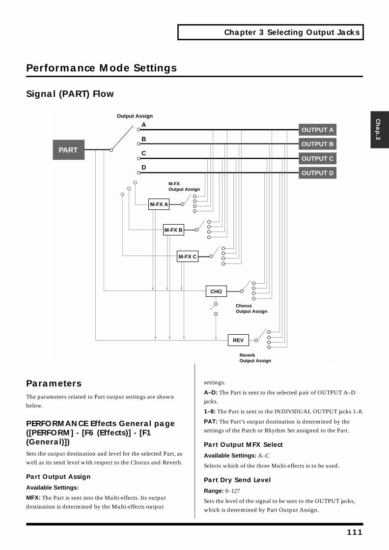
Chapter 3 Selecting Output Jacks
Chap.3
Performance Mode Settings
Signal (PART) Flowfig.03-002.e
ParametersThe parameters related to Part output settings are shown below.
PERFORMANCE Effects General page ([PERFORM] - [F6 (Effects)] - [F1 (General)])Sets the output destination and level for the selected Part, as well as its send level with respect to the Chorus and Reverb.
Part Output Assign
Available Settings:
MFX: The Part is sent into the Multi-effects. Its output destination is determined by the Multi-effects output
settings.
A–D: The Part is sent to the selected pair of OUTPUT A–D jacks.
1–8: The Part is sent to the INDIVIDUAL OUTPUT jacks 1–8.
PAT: The Part’s output destination is determined by the settings of the Patch or Rhythm Set assigned to the Part.
Part Output MFX Select
Available Settings: A–C
Selects which of the three Multi-effects is to be used.
Part Dry Send Level
Range: 0–127
Sets the level of the signal to be sent to the OUTPUT jacks, which is determined by Part Output Assign.
B
A
C
D
CHO
PARTOUTPUT B
OUTPUT C
OUTPUT D
REV
Output Assign
M-FXOutput Assign
ChorusOutput Assign
ReverbOutput Assign
OUTPUT A
M-FX A
M-FX B
M-FX C
111
Chapter 3 Selecting Output Jacks
Part Chorus Send Level
Range: 0–127
Sets how much of the Part is sent to the Chorus. Its final output destination is determined by the Chorus output setting.
Part Reverb Send Level
Range: 0–127
Sets how much of the Part is sent to the Reverb. Its final output destination is determined by the Reverb output setting.
MFX Dry Send Level
Range: 0–127
Determines the level of the signal that is to be sent to the output jacks, after passing through the Multi-effects.
MFX Chorus Send Level
Range: 0–127
Determines the level of the signal that is to be sent to Chorus, after passing through the Multi-effects. Its final output destination is determined by the Chorus output setting.
MFX Reverb Send Level
Range: 0–127
Determines the level of the signal that is to be sent to Reverb, after passing through the Multi-effects. Its final output destination is determined by the Reverb output setting.
Chorus Output Select
Specifies how the signal routed through Chorus will be output.
Available Settings:
MAIN: The Chorus output is sent only to the OUTPUT jacks.
REV: The Chorus output is sent only to the Reverb.
M+R: The Chorus output is sent to the OUTPUT jacks and to the Reverb.
Chorus Level
Range: 0–127
Determines the Chorus output level.
Reverb Level
Range: 0–127
Determines the Reverb output level.
MFX Output Assign
Range: A–D
Selects the pair of OUTPUT jacks to which the Multi-effects stereo output is routed.
* As the Multi-effects are in stereo, settings for the
INDIVIDUAL OUTPUT jacks are unavailable.
Chorus Output Assign
Range: A–D
Selects the pair of OUTPUT jacks to which the Chorus unit’s stereo output is routed when Chorus Output Select is set to “MAIN” or “M+R.” The output destination setting for the signal sent to Reverb is determined according to the Reverb settings.
* As the internal effects processors are in stereo, settings for the
INDIVIDUAL OUTPUT jacks are unavailable.
Reverb Output Assign
Range: A–D
Selects the OUTPUT jacks to which the Reverb unit’s stereo output is routed.
* As the internal effects processors are in stereo, settings for the
INDIVIDUAL OUTPUT jacks are unavailable.
SYSTEM Output page ([SYSTEM] - [F2 (OutP&EQ)])
Output Mix/Parallel
Mode
Available Settings:
MIX: All sounds—including those routed to OUTPUTs B/C or INDIVIDUAL 3–8—are mixed together and routed to the A (MIX) OUTPUT jacks. This setting allows you to quickly route everything through headphones when you are creating sounds, or to combine all of your sounds into two outputs when sending the XV-5080’s signal to a mixer that has only two channels.
When MIX is selected, sounds routed to the INDIVIDUAL OUTPUT 3/5/7 jacks are sent to the left A (MIX) OUTPUT jack, and sounds routed to the INDIVIDUAL OUTPUT 4/6/8 jacks are sent to the right A (MIX) OUTPUT jack.
PARALLEL: Sounds are routed to output jacks according to their output settings.
The XV-5080’s Master Level and Mix/Parallel settings are each established using a single global parameter.
112
Chapter 3 Selecting Output Jacks
Chap.3
SYSTEM General #1 page ([SYSTEM] - [F1 (General)])
Master
Level (Master Level)
Range: 0–127
Adjusts the volume of the entire XV-5080.
Example of Settings
Selecting Different Output Destinations for Parts in a PerformanceThis example describes the procedure for outputting Part 1 from the A (MIX) OUTPUT jacks without sending it through any internal effects, sending Part 2 through the Multi-effects A and then outputting it from the B OUTPUT jack, and outputting Part 3 from the INDIVIDUAL 5 OUTPUT jack without sending it through any internal effects.
First, set Part 1.
1. Select the Performance you wish to use.
2. Press [F6 (Effects)].
3. Press [F1 (General)] several times to call up the Performance Effects General #1 page.
4. Press PART SELECT [1/17] to make its indicator light.
* Make sure that the [1-16/17-32] button’s indicator is not lit. If
the indicator is lit, press [1-16/17-32] to turn it off.
5. Press [ ]/[ ]/[ ]/[ ] to move the cursor to Part Output Assign.
6. Turn the VALUE dial or press [INC]/[DEC] to select “A.”
7. Press [ ]/[ ]/[ ]/[ ] to move the cursor to Part Dry Send Level.
8. Turn the VALUE dial to select “100.”
9. Press [ ]/[ ]/[ ]/[ ] to move the cursor to Part Chorus Send Level.
10. Turn the VALUE dial to select “0.”
11. Set the Part Reverb Send Level setting to “0” in the same way.
Next, set up Part 2.
12. Press PART SELECT [2/18], getting its indicator to light.
* Make sure that the [1-16/17-32] button’s indicator is not lit. If
the indicator is lit, press [1-16/17-32] to turn it off.
13. Press [ ]/[ ]/[ ]/[ ] to move the cursor to the parameter you wish to set, and rotate the VALUE dial, or press [INC] or [DEC] to set the value as follows.
Part Output Part Dry Part Chorus Part Reverb
Assign Send Level Send Level Send Level
MFX-A 100 0 0
The Part Dry Send Level can be set to any value you wish other than 0.
14. Press [ ]/[ ]/[ ]/[ ] to move the cursor to the parameter you wish to set, and rotate the VALUE dial, or press [INC] or [DEC] to set the value as follows.
MFX MFX Dry MFX Chorus MFX Reverb
Output Assign Level Send Level Send Level
B 100 0 0
Finally, set up Part 3.
15. Press PART SELECT [3/19], getting its indicator to light.
* Make sure that the [1-16/17-32] button’s indicator is not lit. If
the indicator is lit, press [1-16/17-32] to turn it off.
16. Press [ ]/[ ]/[ ]/[ ] to move the cursor to the parameter you wish to set, and rotate the VALUE dial, or press [INC] or [DEC] to set the value as follows.
Part Output Part Chorus Part Reverb
Assign Send Level Send Level
5 0 0
The output level can be set to any value you wish other than 0.
17. Press [EXIT] to return to the PERFORM PLAY page.
113
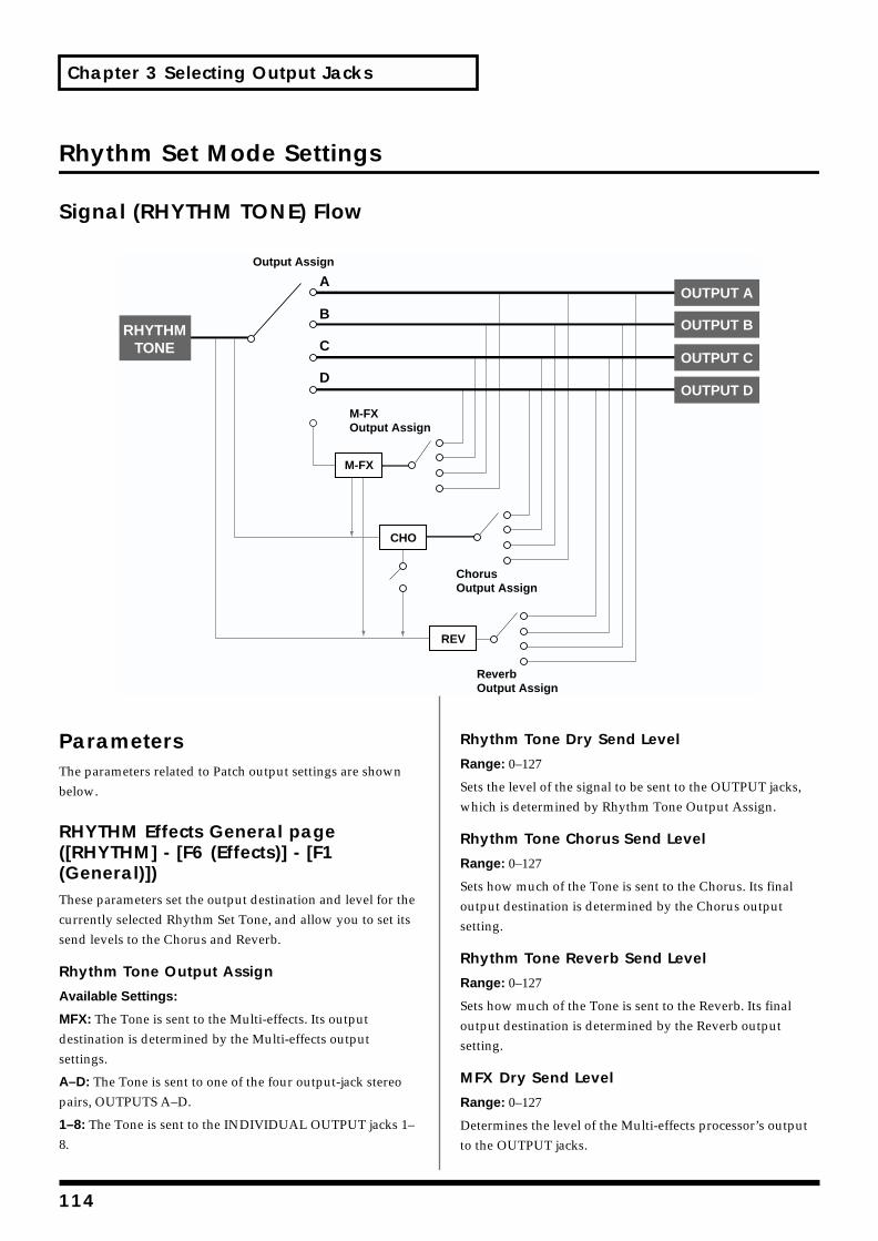
Chapter 3 Selecting Output Jacks
Rhythm Set Mode Settings
Signal (RHYTHM TONE) Flowfig.03-003.e
ParametersThe parameters related to Patch output settings are shown below.
RHYTHM Effects General page ([RHYTHM] - [F6 (Effects)] - [F1 (General)])These parameters set the output destination and level for the currently selected Rhythm Set Tone, and allow you to set its send levels to the Chorus and Reverb.
Rhythm Tone Output Assign
Available Settings:
MFX: The Tone is sent to the Multi-effects. Its output destination is determined by the Multi-effects output settings.
A–D: The Tone is sent to one of the four output-jack stereo pairs, OUTPUTS A–D.
1–8: The Tone is sent to the INDIVIDUAL OUTPUT jacks 1–8.
Rhythm Tone Dry Send Level
Range: 0–127
Sets the level of the signal to be sent to the OUTPUT jacks, which is determined by Rhythm Tone Output Assign.
Rhythm Tone Chorus Send Level
Range: 0–127
Sets how much of the Tone is sent to the Chorus. Its final output destination is determined by the Chorus output setting.
Rhythm Tone Reverb Send Level
Range: 0–127
Sets how much of the Tone is sent to the Reverb. Its final output destination is determined by the Reverb output setting.
MFX Dry Send Level
Range: 0–127
Determines the level of the Multi-effects processor’s output to the OUTPUT jacks.
B
A
C
D
CHO
RHYTHMTONE
OUTPUT B
OUTPUT C
OUTPUT D
REV
M-FX
Output Assign
M-FXOutput Assign
ChorusOutput Assign
ReverbOutput Assign
OUTPUT A
114

Chapter 3 Selecting Output Jacks
Chap.3
MFX Chorus Send Level
Range: 0–127
Determines the level of the post-Multi-effects processor signal sent to Chorus. Its final output destination is determined by the Chorus output setting.
MFX Reverb Send Level
Range: 0–127
Determines the level of the post-Multi-effects processor signal sent to Reverb. Its final output destination is determined by the Reverb output setting.
Chorus Output Select
Specifies how the signal routed through Chorus will be output.
Available Settings:
MAIN: The Chorus output is sent only to the OUTPUT jacks.
REV: The Chorus output is sent only to the Reverb.
M+R: The Chorus output is sent to the OUTPUT jacks and to the Reverb.
Chorus Level
Range: 0–127
Determines the Chorus output level.
Reverb Level
Range: 0–127
Determines the Reverb output level.
MFX Output Assign
Range: A–D
Selects the pair of OUTPUT jacks to which the Multi-effects stereo output is routed.
* As the Multi-effects are in stereo, settings for the
INDIVIDUAL OUTPUT jacks are unavailable.
Chorus Output Assign
Range: A–D
Selects the pair of OUTPUT jacks to which the Chorus unit’s stereo output is routed when Chorus Output Select is set to “MAIN” or “M+R.” The output destination setting for the signal sent to Reverb is determined according to the Reverb settings.
* As the internal effects processors are in stereo, settings for the
INDIVIDUAL OUTPUT jacks are unavailable.
Reverb Output Assign
Range: A–D
Selects the OUTPUT jacks to which the Reverb unit’s stereo output is routed.
* As the internal effects devices are in stereo, you cannot make
the settings for the INDIVIDUAL OUTPUT jacks.
RHYTHM Common page ([RHYTHM] - [F1 (Common)])
Common
Level (Rhythm Level)
Range: 0–127
Sets the volume of the Rhythm Set.
* You can specify the level for each Rhythm Tone using the Tone
Level parameter (p. 177).
Output Assign (Rhythm Set Output Assign)
Available Settings:
MFX: The Tone is sent into the Multi-effects. Its output destination is determined by the Multi-effects output settings.
OUTPUT A–D: The Rhythm Tone is sent to the selected OUTPUT A–D jacks.
INDIV 1–8: The Tone is sent to the INDIVIDUAL OUTPUT jacks 1–8.
TONE: Outputs according to the settings for each Rhythm Tone.
115
Chapter 3 Selecting Output Jacks
SYSTEM Output page ([SYSTEM] - [F2 (OutP&EQ)])
Output Mix/Parallel
Mode
Available Settings:
MIX: Signals that are set to be output from jacks other than the A (MIX) OUTPUT jacks are mixed and output from the A (MIX) OUTPUT jacks. This setting allows you to quickly route everything through headphones when you are creating sounds, or to combine all of your sounds into two outputs when sending the XV-5080’s signal to a mixer that has only two channels.
When MIX is selected, sounds routed to the INDIVIDUAL OUTPUT 3/5/7 jacks are sent to the left A (MIX) OUTPUT jack, and sounds routed to the INDIVIDUAL OUTPUT 4/6/8 jacks are sent to the right A (MIX) OUTPUT jack.
PARALLEL: Sounds are routed to output jacks according to their output settings.
The XV-5080’s Master Level and Mix/Parallel settings are each established using a single global parameter.
SYSTEM General #1 page ([SYSTEM] - [F1 (General)])
Master
Level (Master Level)
Range: 0–127
Adjusts the volume of the entire XV-5080.
Example Settings
Setting the Output Destination of a Specific Rhythm Tone
This example explains the procedure for outputting the Rhythm Tone assigned to C4 from the INDIVIDUAL 3 OUTPUT jack without sending it through any internal effects.
1. Select the Rhythm Set you wish to set.
2. Press [F6 (Effects)].
3. Press [F1 (General)] to call up the RHYTHM Effects General page.
4. Press TONE SELECT [1]–[4] and set the key at the upper left corner of the display to “C4.”
* If a MIDI keyboard is connected, you can select C4 by pressing
the C4 key on the keyboard.
5. Press [ ]/[ ]/[ ]/[ ] to move the cursor to Rhythm Tone Output Assign.
6. Turn the VALUE dial or press [INC]/[DEC] to select “3.”
7. Press [ ]/[ ]/[ ]/[ ] to move the cursor to Rhythm Tone Dry Send Level.
8. Turn the VALUE dial to select “100.”
9. Press [ ]/[ ]/[ ]/[ ] to move the cursor to Rhythm Tone Chorus Send Level.
10. Turn the VALUE dial to select “0.”
11. Set the Rhythm Tone Reverb Send Level setting to “0” in the same way.
12. Press [EXIT] to return to the RHYTHM PLAY page.
13. Press [F1 (Common)].
14. Press [ ]/[ ] to move the cursor to Output Assign.
15. Turn the VALUE dial or press [INC]/[DEC] to select “TONE.”
16. Press [EXIT] to return to the RHYTHM PLAY page.
116
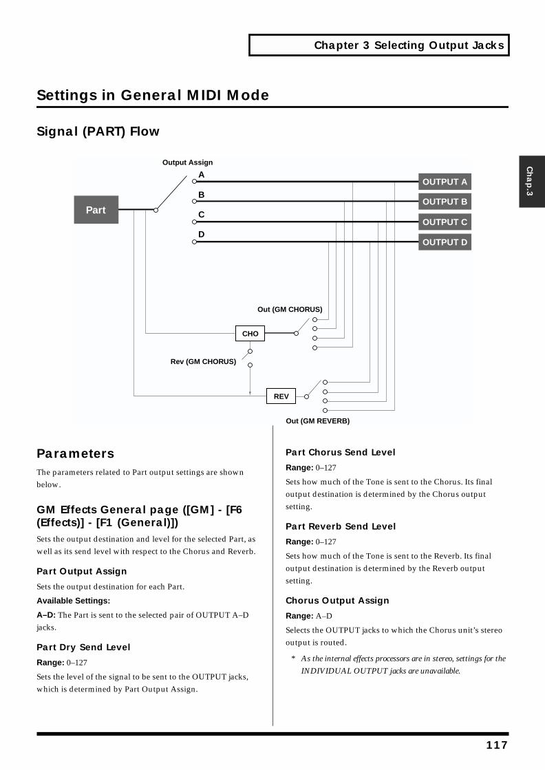
Chapter 3 Selecting Output Jacks
Chap.3
Settings in General MIDI Mode
Signal (PART) Flowfig.03-004.e
ParametersThe parameters related to Part output settings are shown below.
GM Effects General page ([GM] - [F6 (Effects)] - [F1 (General)])Sets the output destination and level for the selected Part, as well as its send level with respect to the Chorus and Reverb.
Part Output Assign
Sets the output destination for each Part.
Available Settings:
A–D: The Part is sent to the selected pair of OUTPUT A–D jacks.
Part Dry Send Level
Range: 0–127
Sets the level of the signal to be sent to the OUTPUT jacks, which is determined by Part Output Assign.
Part Chorus Send Level
Range: 0–127
Sets how much of the Tone is sent to the Chorus. Its final output destination is determined by the Chorus output setting.
Part Reverb Send Level
Range: 0–127
Sets how much of the Tone is sent to the Reverb. Its final output destination is determined by the Reverb output setting.
Chorus Output Assign
Range: A–D
Selects the OUTPUT jacks to which the Chorus unit’s stereo output is routed.
* As the internal effects processors are in stereo, settings for the
INDIVIDUAL OUTPUT jacks are unavailable.
B
A
C
D
CHO
PartOUTPUT B
OUTPUT C
OUTPUT D
REV
Output Assign
Out (GM CHORUS)
Rev (GM CHORUS)
Out (GM REVERB)
OUTPUT A
117
Chapter 3 Selecting Output Jacks
Reverb Send Level
Range: 0–127
Sets the amount of the Chorus unit’s output to be sent to the Reverb. Its final output destination is determined by the Reverb output setting.
Reverb Output Assign
Range: A–D
Selects the OUTPUT jacks to which the Reverb unit’s stereo output is routed.
* As the internal effects processors are in stereo, settings for the
INDIVIDUAL OUTPUT jacks are unavailable.
SYSTEM Output page ([SYSTEM] - [F2 (OutP&EQ)])
Output Mix/Parallel
Mode
Available Settings:
MIX: Signals that are set to be output from jacks other than the A (MIX) OUTPUT jacks are mixed and output from the A (MIX) OUTPUT jacks. This setting allows you to quickly route everything through headphones when you are creating sounds, or to combine all of your sounds into two outputs when sending the XV-5080’s signal to a mixer that has only two channels.
When MIX is selected, sounds routed to the INDIVIDUAL OUTPUT 3/5/7 jacks are sent to the left A (MIX) OUTPUT jack, and sounds routed to the INDIVIDUAL OUTPUT 4/6/8 jacks are sent to the right A (MIX) OUTPUT jack.
PARALLEL: Sounds are routed to output jacks according to their output settings.
The XV-5080’s Master Level and Mix/Parallel settings are each established using a single global parameter.
SYSTEM General #1 page ([SYSTEM] - [F1 (General)])
Master
Level (Master Level)
Range: 0–127
Adjusts the volume of the entire XV-5080.
118
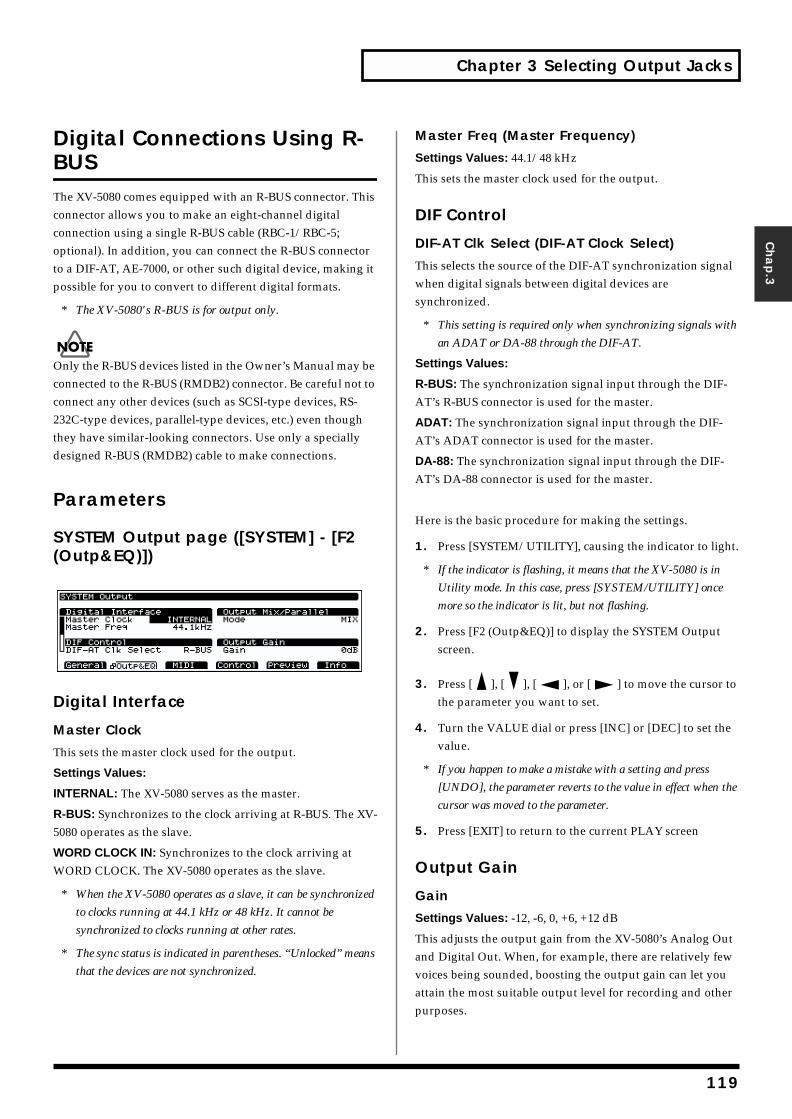
Chapter 3 Selecting Output Jacks
Chap.3
Digital Connections Using R-BUSThe XV-5080 comes equipped with an R-BUS connector. This connector allows you to make an eight-channel digital connection using a single R-BUS cable (RBC-1/RBC-5; optional). In addition, you can connect the R-BUS connector to a DIF-AT, AE-7000, or other such digital device, making it possible for you to convert to different digital formats.
* The XV-5080's R-BUS is for output only.
Only the R-BUS devices listed in the Owner’s Manual may be connected to the R-BUS (RMDB2) connector. Be careful not to connect any other devices (such as SCSI-type devices, RS-232C-type devices, parallel-type devices, etc.) even though they have similar-looking connectors. Use only a specially designed R-BUS (RMDB2) cable to make connections.
Parameters
SYSTEM Output page ([SYSTEM] - [F2 (Outp&EQ)])
Digital Interface
Master Clock
This sets the master clock used for the output.
Settings Values:
INTERNAL: The XV-5080 serves as the master.
R-BUS: Synchronizes to the clock arriving at R-BUS. The XV-5080 operates as the slave.
WORD CLOCK IN: Synchronizes to the clock arriving at WORD CLOCK. The XV-5080 operates as the slave.
* When the XV-5080 operates as a slave, it can be synchronized
to clocks running at 44.1 kHz or 48 kHz. It cannot be
synchronized to clocks running at other rates.
* The sync status is indicated in parentheses. “Unlocked” means
that the devices are not synchronized.
Master Freq (Master Frequency)
Settings Values: 44.1/48 kHz
This sets the master clock used for the output.
DIF Control
DIF-AT Clk Select (DIF-AT Clock Select)
This selects the source of the DIF-AT synchronization signal when digital signals between digital devices are synchronized.
* This setting is required only when synchronizing signals with
an ADAT or DA-88 through the DIF-AT.
Settings Values:
R-BUS: The synchronization signal input through the DIF-AT’s R-BUS connector is used for the master.
ADAT: The synchronization signal input through the DIF-AT’s ADAT connector is used for the master.
DA-88: The synchronization signal input through the DIF-AT’s DA-88 connector is used for the master.
Here is the basic procedure for making the settings.
1. Press [SYSTEM/UTILITY], causing the indicator to light.
* If the indicator is flashing, it means that the XV-5080 is in
Utility mode. In this case, press [SYSTEM/UTILITY] once
more so the indicator is lit, but not flashing.
2. Press [F2 (Outp&EQ)] to display the SYSTEM Output screen.
3. Press [ ], [ ], [ ], or [ ] to move the cursor to the parameter you want to set.
4. Turn the VALUE dial or press [INC] or [DEC] to set the value.
* If you happen to make a mistake with a setting and press
[UNDO], the parameter reverts to the value in effect when the
cursor was moved to the parameter.
5. Press [EXIT] to return to the current PLAY screen
Output Gain
Gain
Settings Values: -12, -6, 0, +6, +12 dB
This adjusts the output gain from the XV-5080’s Analog Out and Digital Out. When, for example, there are relatively few voices being sounded, boosting the output gain can let you attain the most suitable output level for recording and other purposes.
119
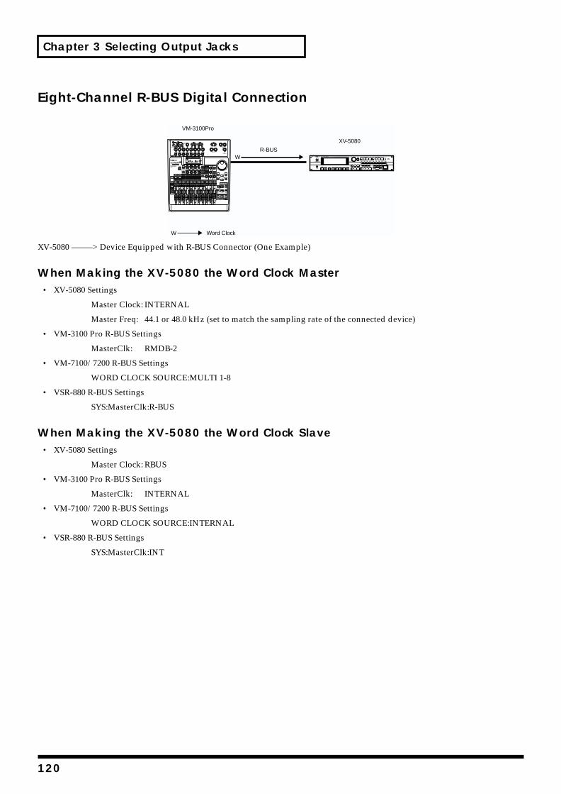
Chapter 3 Selecting Output Jacks
Eight-Channel R-BUS Digital Connectionfig.RBUS-1.e
XV-5080 ——–> Device Equipped with R-BUS Connector (One Example)
When Making the XV-5080 the Word Clock Master• XV-5080 Settings
Master Clock: INTERNAL
Master Freq: 44.1 or 48.0 kHz (set to match the sampling rate of the connected device)
• VM-3100 Pro R-BUS Settings
MasterClk: RMDB-2
• VM-7100/7200 R-BUS Settings
WORD CLOCK SOURCE:MULTI 1-8
• VSR-880 R-BUS Settings
SYS:MasterClk:R-BUS
When Making the XV-5080 the Word Clock Slave• XV-5080 Settings
Master Clock: RBUS
• VM-3100 Pro R-BUS Settings
MasterClk: INTERNAL
• VM-7100/7200 R-BUS Settings
WORD CLOCK SOURCE:INTERNAL
• VSR-880 R-BUS Settings
SYS:MasterClk:INT
VM-3100Pro
R-BUS
XV-5080
W
Word ClockW
120
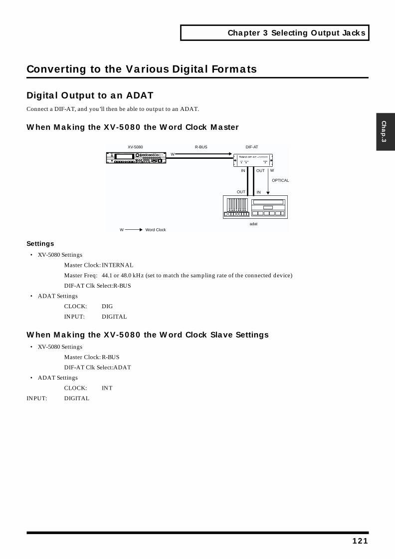
Chapter 3 Selecting Output Jacks
Chap.3
Converting to the Various Digital Formats
Digital Output to an ADATConnect a DIF-AT, and you’ll then be able to output to an ADAT.
When Making the XV-5080 the Word Clock Masterfig.RBUS-2.e
Settings
• XV-5080 Settings
Master Clock: INTERNAL
Master Freq: 44.1 or 48.0 kHz (set to match the sampling rate of the connected device)
DIF-AT Clk Select:R-BUS
• ADAT Settings
CLOCK: DIG
INPUT: DIGITAL
When Making the XV-5080 the Word Clock Slave Settings• XV-5080 Settings
Master Clock: R-BUS
DIF-AT Clk Select:ADAT
• ADAT Settings
CLOCK: INT
INPUT: DIGITAL
POWER
OPTICAL
R-BUS DIF-AT
adat
XV-5080
W
WIN
IN
OUT
OUT
Word ClockW
121
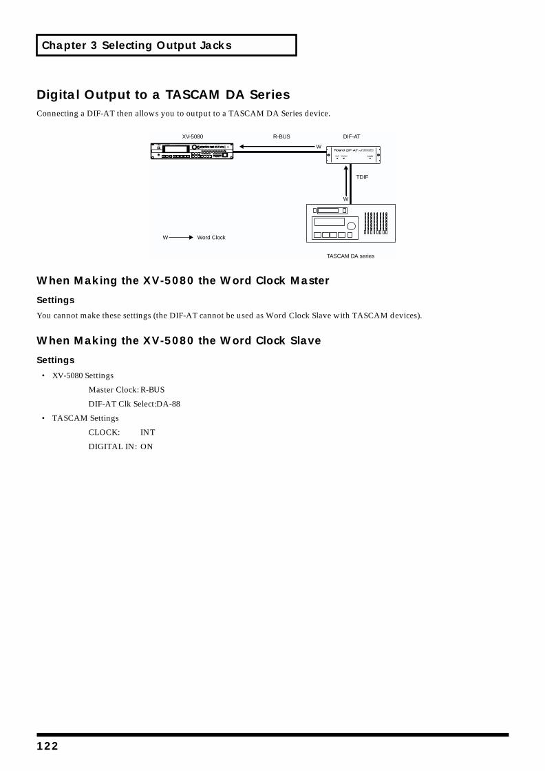
Chapter 3 Selecting Output Jacks
Digital Output to a TASCAM DA SeriesConnecting a DIF-AT then allows you to output to a TASCAM DA Series device.fig.RBUS-3.e
When Making the XV-5080 the Word Clock Master
Settings
You cannot make these settings (the DIF-AT cannot be used as Word Clock Slave with TASCAM devices).
When Making the XV-5080 the Word Clock Slave
Settings
• XV-5080 Settings
Master Clock: R-BUS
DIF-AT Clk Select:DA-88
• TASCAM Settings
CLOCK: INT
DIGITAL IN: ON
POWER
R-BUS DIF-ATXV-5080
TDIF
TASCAM DA series
W
W
Word ClockW
122
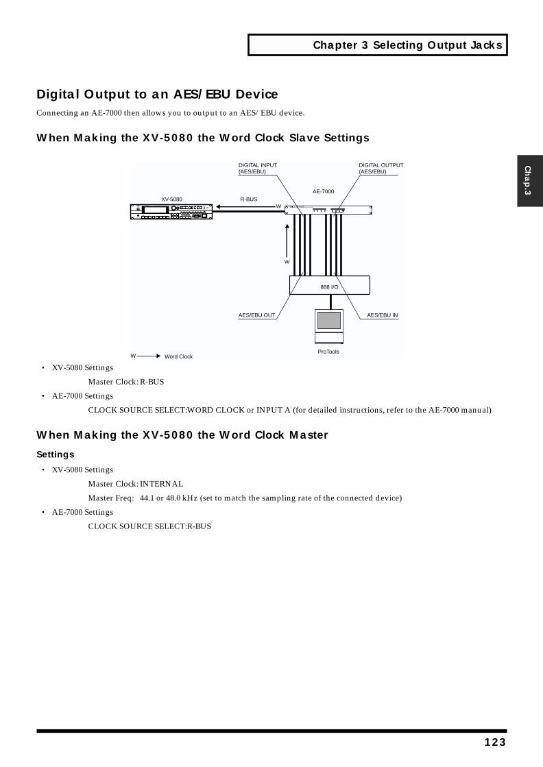
Chapter 3 Selecting Output Jacks
Chap.3
Digital Output to an AES/EBU DeviceConnecting an AE-7000 then allows you to output to an AES/EBU device.
When Making the XV-5080 the Word Clock Slave Settingsfig.RBUS-4.e
• XV-5080 Settings
Master Clock: R-BUS
• AE-7000 Settings
CLOCK SOURCE SELECT:WORD CLOCK or INPUT A (for detailed instructions, refer to the AE-7000 manual)
When Making the XV-5080 the Word Clock Master
Settings
• XV-5080 Settings
Master Clock: INTERNAL
Master Freq: 44.1 or 48.0 kHz (set to match the sampling rate of the connected device)
• AE-7000 Settings
CLOCK SOURCE SELECT:R-BUS
Word Clock
XV-5080
888 I/O
AE-7000
ProTools
R-BUS
DIGITAL OUTPUT(AES/EBU)
DIGITAL INPUT(AES/EBU)
AES/EBU INAES/EBU OUT
W
W
W
123
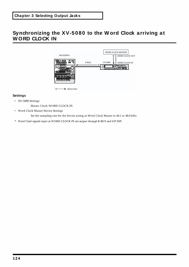
Chapter 3 Selecting Output Jacks
Synchronizing the XV-5080 to the Word Clock arriving at WORD CLOCK INfig.RBUS-6.e
Settings
• XV-5080 Settings
Master Clock: WORD CLOCK IN
• Word Clock Master Device Settings
Set the sampling rate for the device acting as Word Clock Master to 44.1 or 48.0 kHz.
* Word Clock signals input at WORD CLOCK IN are output through R-BUS and S/P DIF.
VM-3100Pro
R-BUS XV-5080
WORD CLOCK MASTER
WORD CLOCK OUT
WORD CLOCK INW
W
Word ClockW
124
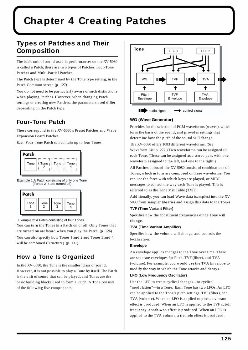
Chapter 4 Creating Patches
Types of Patches and Their CompositionThe basic unit of sound used in performances on the XV-5080 is called a Patch; there are two types of Patches, Four-Tone Patches and Multi-Partial Patches.
The Patch type is determined by the Tone type setting, in the Patch Common screen (p. 127).
You do not need to be particularly aware of such distinctions when playing Patches. However, when changing Patch settings or creating new Patches, the parameters used differ depending on the Patch type.
Four-Tone PatchThese correspond to the XV-5080’s Preset Patches and Wave Expansion Board Patches.
Each Four-Tone Patch can contain up to four Tones.fig.04-001.e
You can turn the Tones in a Patch on or off. Only Tones that are turned on are heard when you play the Patch. (p. 126)
You can also specify how Tones 1 and 2 and Tones 3 and 4 will be combined (Structure). (p. 131)
How a Tone Is OrganizedIn the XV-5080, the Tone is the smallest class of sound. However, it is not possible to play a Tone by itself. The Patch is the unit of sound that can be played, and Tones are the basic building blocks used to form a Patch. A Tone consists of the following five components.
fig.04-002.e
WG (Wave Generator)
Provides for the selection of PCM waveforms (waves), which form the basis of the sound, and provides settings that determine how the pitch of the sound will change.
The XV-5080 offers 1083 different waveforms. (See Waveform List p. 277.) Two waveforms can be assigned to each Tone. (These can be assigned as a stereo pair, with one waveform assigned to the left, and one to the right.)
All Patches onboard the XV-5080 consist of combinations of Tones, which in turn are composed of these waveforms. You can use the force with which keys are played, or MIDI messages to control the way each Tone is played. This is referred to as the Tone Mix Table (TMT).
Additionally, you can load Wave data (samples) into the XV-5080 from sampler libraries and assign this data to the Tones.
TVF (Time Variant Filter)
Specifies how the constituent frequencies of the Tone will change.
TVA (Time Variant Amplifier)
Specifies how the volume will change, and controls the localization.
Envelope
An envelope applies changes to the Tone over time. There are separate envelopes for Pitch, TVF (filter), and TVA (volume). For example, you would use the TVA Envelope to modify the way in which the Tone attacks and decays.
LFO (Low Frequency Oscillator)
Use the LFO to create cyclical changes—or cyclical “modulation”—in a Tone. Each Tone has two LFOs. An LFO can be applied to the Tone’s pitch settings, TVF (filter), and TVA (volume). When an LFO is applied to pitch, a vibrato effect is produced. When an LFO is applied to the TVF cutoff frequency, a wah-wah effect is produced. When an LFO is applied to the TVA volume, a tremolo effect is produced.
Example 1:A Patch consisting of only one Tone (Tones 2–4 are turned off).
Example 2: A Patch consisting of four Tones.
Tone1
Tone2
Tone1
Tone4
Tone3
Tone4
Tone2
Tone3
WG
PitchEnvelope
TVF
TVF Envelope
TVA Envelope
TVA
LFO 1 LFO 2Tone
audio signal control signal
125

126
Chapter 4 Creating Patches
Multi-partial Pat
Patches using data loaded int
libraries are of this type.
Multi-Partial Patches are creasounds, called Partials, to theto 88 Partials being assignabl
One difference between ToneTones are composed of two wup to four samples (Wave da
* Multi-Partial Patches are c
loaded into the SIMM (mem
cannot be used). To do this,
the samples from a sampler
5080. (p. 181)
How a Partial Is
The sounds from which Mult
are called Partials. Partials maand are composed using the f
SMT (Sample Mix Table)
Selects the sample to be used
You can use the key touch anway each sample is played.
Multi-Partial Patch
B1
D7 S
S
S
S
SMT TV
TVEnve
LFOPartial
audio signal
cho the XV-5080 from sampler
ted by assigning the constituent keys on the keyboard, with up e.
s and Partials is that whereas aveforms, Partials may contain
ta).
reated using samples (Wave data)
ory module) (internal Waves
you need a separate device to load
library or other source to the XV-
Organizedi-Partial Patches are composed
y comprise up to four samples, ollowing five elements.
as the source of the sound.
d MIDI messages to control the
TVF (Time Variant Filter)
Specifies how the constituent frequencies of the Tone will change.
TVA (Time Variant Amplifier)
Specifies how the volume will change, and controls the localization.
Envelope
An envelope applies changes to the Tone over time. There are separate envelopes for Pitch, TVF (filter), and TVA (volume). For example, you would use the TVA Envelope to modify the way in which the Tone attacks and decays.
The TVF envelope can be used to change not only the cutoff frequency, but also the pitch.
LFO (Low Frequency Oscillator)
Use the LFO to create cyclical changes—or cyclical “modulation”—in a Tone. Each Tone has an LFO. An LFO can be applied to the Tone’s pitch settings, TVF (filter), and TVA (volume). When an LFO is applied to pitch, a vibrato effect is produced. When an LFO is applied to the TVF cutoff frequency, a wah-wah effect is produced. When an LFO is applied to the TVA volume, a tremolo effect is produced.
Selecting the Tones That Will Sound (Tone On/Off)Here’s how to turn on the Tones that you want to hear in a Patch. You can also use the on/off technique described in this section to audition an individual Tone by turning off all the other Tones in a Patch.
Select the Patch you wish to use.
1. Make sure that the PATCH PLAY page is displayed.
2. Hold down [SHIFT] and press TONE SW [1]–[4] to switch the corresponding Tone on so that its indicator lights, or off so that its indicator goes dark.
3. The PATCH PLAY page indicates the Tones that are on as follows. Tones that are off are shown as “-.”
fig.04-003.e
Partial
88 Partials
ample 1
ample 2
ample 3
ample 4
F
F lope
TVA Envelope
TVA
control signal
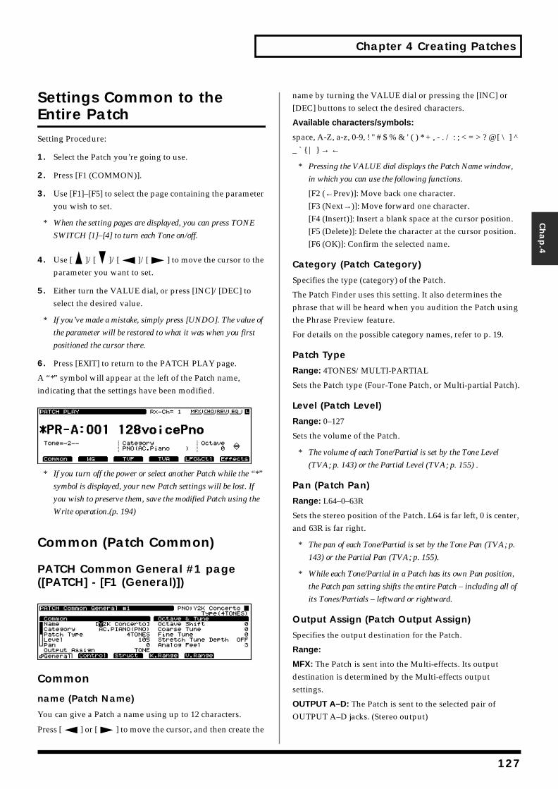
Chapter 4 Creating Patches
Chap.4
Settings Common to the Entire PatchSetting Procedure:
1. Select the Patch you’re going to use.
2. Press [F1 (COMMON)].
3. Use [F1]–[F5] to select the page containing the parameter you wish to set.
* When the setting pages are displayed, you can press TONE
SWITCH [1]–[4] to turn each Tone on/off.
4. Use [ ]/[ ]/[ ]/[ ] to move the cursor to the parameter you want to set.
5. Either turn the VALUE dial, or press [INC]/[DEC] to select the desired value.
* If you’ve made a mistake, simply press [UNDO]. The value of
the parameter will be restored to what it was when you first
positioned the cursor there.
6. Press [EXIT] to return to the PATCH PLAY page.
A “*” symbol will appear at the left of the Patch name, indicating that the settings have been modified.fig.04-004.e_70
* If you turn off the power or select another Patch while the “*”
symbol is displayed, your new Patch settings will be lost. If
you wish to preserve them, save the modified Patch using the
Write operation.(p. 194)
Common (Patch Common)
PATCH Common General #1 page ([PATCH] - [F1 (General)])fig.04-005.e_70
Common
name (Patch Name)
You can give a Patch a name using up to 12 characters.
Press [ ] or [ ] to move the cursor, and then create the
name by turning the VALUE dial or pressing the [INC] or [DEC] buttons to select the desired characters.
Available characters/symbols:
space, A-Z, a-z, 0-9, ! " # $ % & ' ( ) * + , - . / : ; < = > ? @ [ \ ] ^ _ ` { | } → ←
* Pressing the VALUE dial displays the Patch Name window,
in which you can use the following functions.
[F2 (←Prev)]: Move back one character.[F3 (Next→)]: Move forward one character.[F4 (Insert)]: Insert a blank space at the cursor position.[F5 (Delete)]: Delete the character at the cursor position.[F6 (OK)]: Confirm the selected name.
Category (Patch Category)
Specifies the type (category) of the Patch.
The Patch Finder uses this setting. It also determines the phrase that will be heard when you audition the Patch using the Phrase Preview feature.
For details on the possible category names, refer to p. 19.
Patch Type
Range: 4TONES/MULTI-PARTIAL
Sets the Patch type (Four-Tone Patch, or Multi-partial Patch).
Level (Patch Level)
Range: 0–127
Sets the volume of the Patch.
* The volume of each Tone/Partial is set by the Tone Level
(TVA; p. 143) or the Partial Level (TVA; p. 155) .
Pan (Patch Pan)
Range: L64–0–63R
Sets the stereo position of the Patch. L64 is far left, 0 is center, and 63R is far right.
* The pan of each Tone/Partial is set by the Tone Pan (TVA; p.
143) or the Partial Pan (TVA; p. 155).
* While each Tone/Partial in a Patch has its own Pan position,
the Patch pan setting shifts the entire Patch – including all of
its Tones/Partials – leftward or rightward.
Output Assign (Patch Output Assign)
Specifies the output destination for the Patch.
Range:
MFX: The Patch is sent into the Multi-effects. Its output destination is determined by the Multi-effects output settings.
OUTPUT A–D: The Patch is sent to the selected pair of OUTPUT A–D jacks. (Stereo output)
127
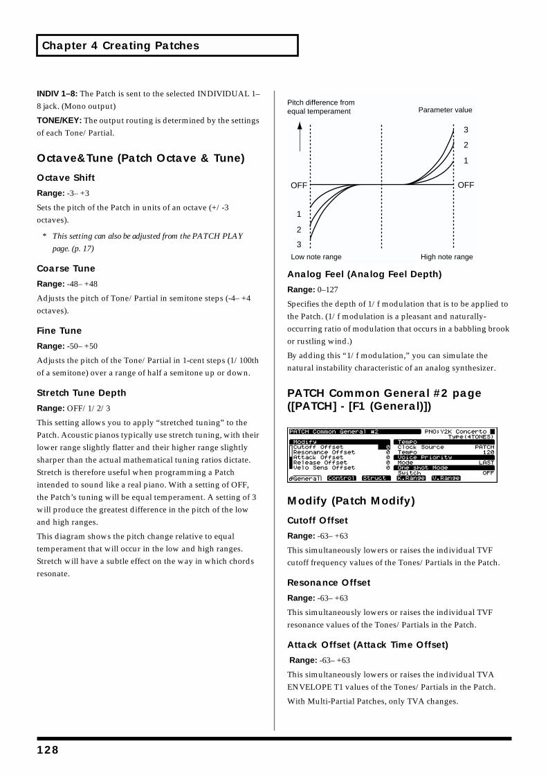
Chapter 4 Creating Patches
INDIV 1–8: The Patch is sent to the selected INDIVIDUAL 1–8 jack. (Mono output)
TONE/KEY: The output routing is determined by the settings of each Tone/Partial.
Octave&Tune (Patch Octave & Tune)
Octave Shift
Range: -3– +3
Sets the pitch of the Patch in units of an octave (+/-3 octaves).
* This setting can also be adjusted from the PATCH PLAY
page. (p. 17)
Coarse Tune
Range: -48– +48
Adjusts the pitch of Tone/Partial in semitone steps (-4– +4 octaves).
Fine Tune
Range: -50– +50
Adjusts the pitch of the Tone/Partial in 1-cent steps (1/100th of a semitone) over a range of half a semitone up or down.
Stretch Tune Depth
Range: OFF/1/2/3
This setting allows you to apply “stretched tuning” to the Patch. Acoustic pianos typically use stretch tuning, with their lower range slightly flatter and their higher range slightly sharper than the actual mathematical tuning ratios dictate. Stretch is therefore useful when programming a Patch intended to sound like a real piano. With a setting of OFF, the Patch’s tuning will be equal temperament. A setting of 3 will produce the greatest difference in the pitch of the low and high ranges.
This diagram shows the pitch change relative to equal temperament that will occur in the low and high ranges. Stretch will have a subtle effect on the way in which chords resonate.
fig.04-006.e
Analog Feel (Analog Feel Depth)
Range: 0–127
Specifies the depth of 1/f modulation that is to be applied to the Patch. (1/f modulation is a pleasant and naturally-occurring ratio of modulation that occurs in a babbling brook or rustling wind.)
By adding this “1/f modulation,” you can simulate the natural instability characteristic of an analog synthesizer.
PATCH Common General #2 page ([PATCH] - [F1 (General)])fig.04-007.e_70
Modify (Patch Modify)
Cutoff Offset
Range: -63– +63
This simultaneously lowers or raises the individual TVF cutoff frequency values of the Tones/Partials in the Patch.
Resonance Offset
Range: -63– +63
This simultaneously lowers or raises the individual TVF resonance values of the Tones/Partials in the Patch.
Attack Offset (Attack Time Offset)
Range: -63– +63
This simultaneously lowers or raises the individual TVA ENVELOPE T1 values of the Tones/Partials in the Patch.
With Multi-Partial Patches, only TVA changes.
1
2
3
OFF
2
1
OFF
3
Pitch difference fromequal temperament Parameter value
Low note range High note range
128
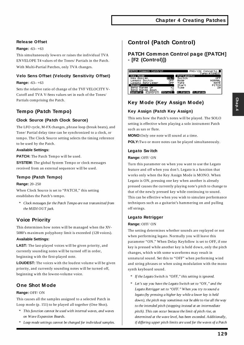
Chapter 4 Creating Patches
Chap.4
Release Offset
Range: -63– +63
This simultaneously lowers or raises the individual TVA ENVELOPE T4 values of the Tones/Partials in the Patch.
With Multi-Partial Patches, only TVA changes.
Velo Sens Offset (Velocity Sensitivity Offset)
Range: -63– +63
Sets the relative ratio of change of the TVF VELOCITY V-Cutoff and TVA V-Sens values set in each of the Tones/Partials comprising the Patch.
Tempo (Patch Tempo)
Clock Source (Patch Clock Source)
The LFO cycle, M-FX changes, phrase loop (break beats), and Tone/Partial delay time can be synchronized to a clock, or tempo. The Clock Source setting selects the timing reference to be used by the Patch.
Available Settings:
PATCH: The Patch Tempo will be used.
SYSTEM: The global System Tempo or clock messages received from an external sequencer will be used.
Tempo (Patch Tempo)
Range: 20–250
When Clock Source is set to “PATCH,” this setting establishes the Patch’s tempo.
* Clock messages for the Patch Tempo are not transmitted from
the MIDI OUT jack.
Voice PriorityThis determines how notes will be managed when the XV-5080’s maximum polyphony limit is exceeded (128 voices).
Available Settings:
LAST: The last-played voices will be given priority, and currently sounding notes will be turned off in order, beginning with the first-played note.
LOUDEST: The voices with the loudest volume will be given priority, and currently sounding notes will be turned off, beginning with the lowest-volume voice.
One Shot ModeRange: OFF/ON
This causes all the samples assigned to a selected Patch in Loop mode (p. 151) to be played all together (One Shot).
* This function cannot be used with internal waves, and waves
on Wave Expansion Boards.
* Loop mode settings cannot be changed for individual samples.
Control (Patch Control)
PATCH Common Control page ([PATCH] - [F2 (Control)])fig.04-008.e_70
Key Mode (Key Assign Mode)
Key Assign (Patch Key Assign)
This sets how the Patch’s notes will be played. The SOLO setting is effective when playing a solo instrument Patch such as sax or flute.
MONO:Only one note will sound at a time.
POLY:Two or more notes can be played simultaneously.
Legato Switch
Range: OFF/ON
Turn this parameter on when you want to use the Legato feature and off when you don’t. Legato is a function that works only when the Key Assign Mode is MONO. When Legato is ON, pressing one key when another is already pressed causes the currently playing note’s pitch to change to that of the newly pressed key while continuing to sound. This can be effective when you wish to simulate performance techniques such as a guitarist’s hammering on and pulling off strings.
Legato Retrigger
Range: OFF/ON
The setting determines whether sounds are replayed or not when performing legato. Normally you will leave this parameter “ON.” When Delay Keyfollow is set to OFF, if one key is pressed while another key is held down, only the pitch changes, which with some waveforms may result in unnatural sound. Set this to “OFF” when performing wind and string phrases or when using modulation with the mono synth keyboard sound.
* If the Legato Switch is “OFF,” this setting is ignored.
* Let’s say you have the Legato Switch set to “ON,” and the
Legato Retrigger set to “OFF.” When you try to sound a
legato (by pressing a higher key while a lower key is held
down), the pitch may sometimes not be able to rise all the way
to the intended pitch (stopping instead at an intermediate
pitch). This can occur because the limit of pitch rise, as
determined at the wave level, has been exceeded. Additionally,
if differing upper pitch limits are used for the waves of a Patch
129
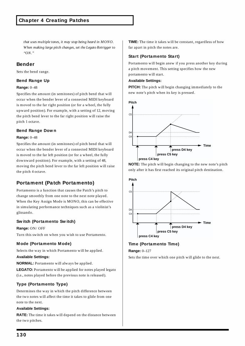
Chapter 4 Creating Patches
that uses multiple tones, it may stop being heard in MONO.
When making large pitch changes, set the Legato Retrigger to
“ON.”
BenderSets the bend range.
Bend Range Up
Range: 0–48
Specifies the amount (in semitones) of pitch bend that will occur when the bender lever of a connected MIDI keyboard is moved to the far right position (or for a wheel, the fully upward position). For example, with a setting of 12, moving the pitch bend lever to the far right position will raise the pitch 1 octave.
Bend Range Down
Range: 0–48
Specifies the amount (in semitones) of pitch bend that will occur when the bender lever of a connected MIDI keyboard is moved to the far left position (or for a wheel, the fully downward position). For example, with a setting of 48, moving the pitch bend lever to the far left position will raise the pitch 4 octave.
Portament (Patch Portamento)Portamento is a function that causes the Patch’s pitch to change smoothly from one note to the next note played. When the Key Assign Mode is MONO, this can be effective in simulating performance techniques such as a violinist’s glissando.
Switch (Portamento Switch)
Range: ON/OFF
Turn this switch on when you wish to use Portamento.
Mode (Portamento Mode)
Selects the way in which Portamento will be applied.
Available Settings:
NORMAL: Portamento will always be applied.
LEGATO: Portamento will be applied for notes played legato (i.e., notes played before the previous note is released).
Type (Portamento Type)
Determines the way in which the pitch difference between the two notes will affect the time it takes to glide from one note to the next.
Available Settings:
RATE: The time it takes will depend on the distance between the two pitches.
TIME: The time it takes will be constant, regardless of how far apart in pitch the notes are.
Start (Portamento Start)
Portamento will begin anew if you press another key during a pitch movement. This setting specifies how the new portamento will start.
Available Settings:
PITCH: The pitch will begin changing immediately to the new note’s pitch when its key is pressed.fig.04-009.e
NOTE: The pitch will begin changing to the new note’s pitch only after it has first reached its original pitch destination.fig.04-010.e
Time (Portamento Time)
Range: 0–127
Sets the time over which one pitch will glide to the next.
C5
D4
C4
press D4 key
Pitch
Time
press C4 keypress C5 key
C5
D4
C4
press D4 key
Pitch
Time
press C4 keypress C5 key
130
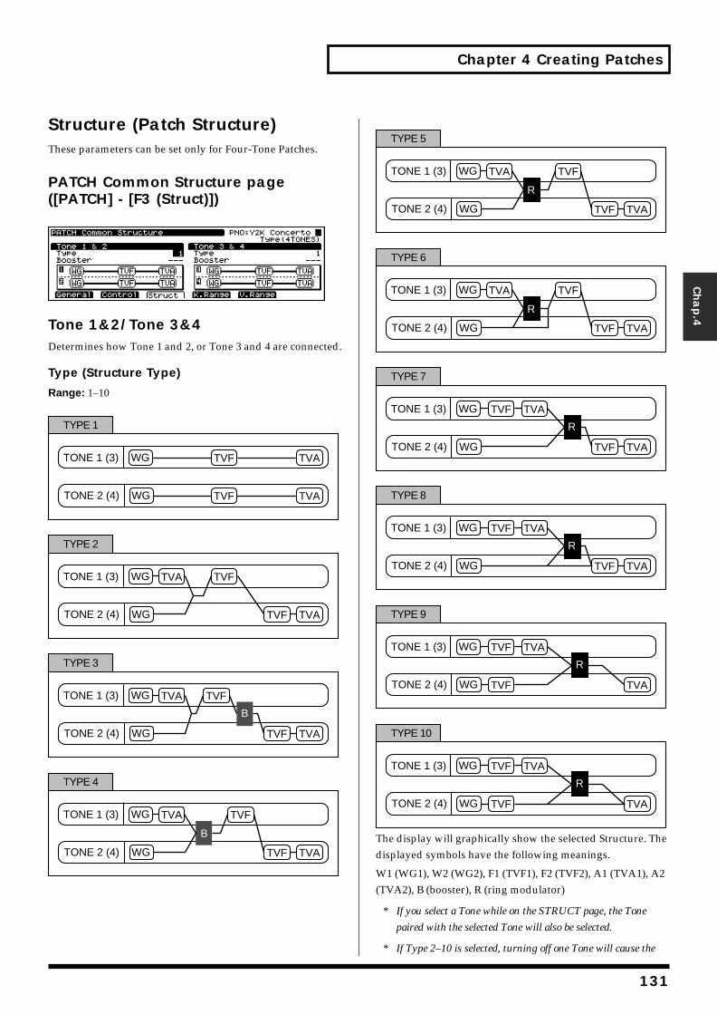
Chapter 4 Creating Patches
Chap.4
Structure (Patch Structure)These parameters can be set only for Four-Tone Patches.
PATCH Common Structure page ([PATCH] - [F3 (Struct)])fig.04-011.e_70
Tone 1&2/Tone 3&4Determines how Tone 1 and 2, or Tone 3 and 4 are connected.
Type (Structure Type)
Range: 1–10fig.04-012.e
fig.04-013.e
fig.04-014.e
fig.04-015.e
fig.04-016.e
fig.04-017.e
fig.04-018.e
fig.04-019.e
fig.04-020.e
fig.04-021.e
The display will graphically show the selected Structure. The displayed symbols have the following meanings.
W1 (WG1), W2 (WG2), F1 (TVF1), F2 (TVF2), A1 (TVA1), A2 (TVA2), B (booster), R (ring modulator)
* If you select a Tone while on the STRUCT page, the Tone
paired with the selected Tone will also be selected.
* If Type 2–10 is selected, turning off one Tone will cause the
TONE 1 (3)
TONE 2 (4)
TVATVFWG
WG TVF TVA
TYPE 1
TONE 1 (3)
TONE 2 (4)
TVA TVFWG
WG TVF TVA
TYPE 2
TONE 1 (3)
TONE 2 (4)
TVA TVFWG
WG TVF TVA
B
TYPE 3
TONE 1 (3)
TONE 2 (4)
TVA TVFWG
WG TVF TVA
B
TYPE 4
TONE 1 (3)
TONE 2 (4)
TVA TVFWG
WG TVF TVA
R
TYPE 5
TONE 1 (3)
TONE 2 (4)
TVA TVFWG
WG TVF TVA
R
TYPE 6
TONE 1 (3)
TONE 2 (4)
TVATVFWG
WG TVF TVA
R
TYPE 7
TONE 1 (3)
TONE 2 (4)
TVATVFWG
WG TVF TVA
R
TYPE 8
TONE 1 (3)
TONE 2 (4)
TVATVFWG
WG TVF TVA
R
TYPE 9
TONE 1 (3)
TONE 2 (4)
TVATVFWG
WG TVF TVA
R
TYPE 10
131
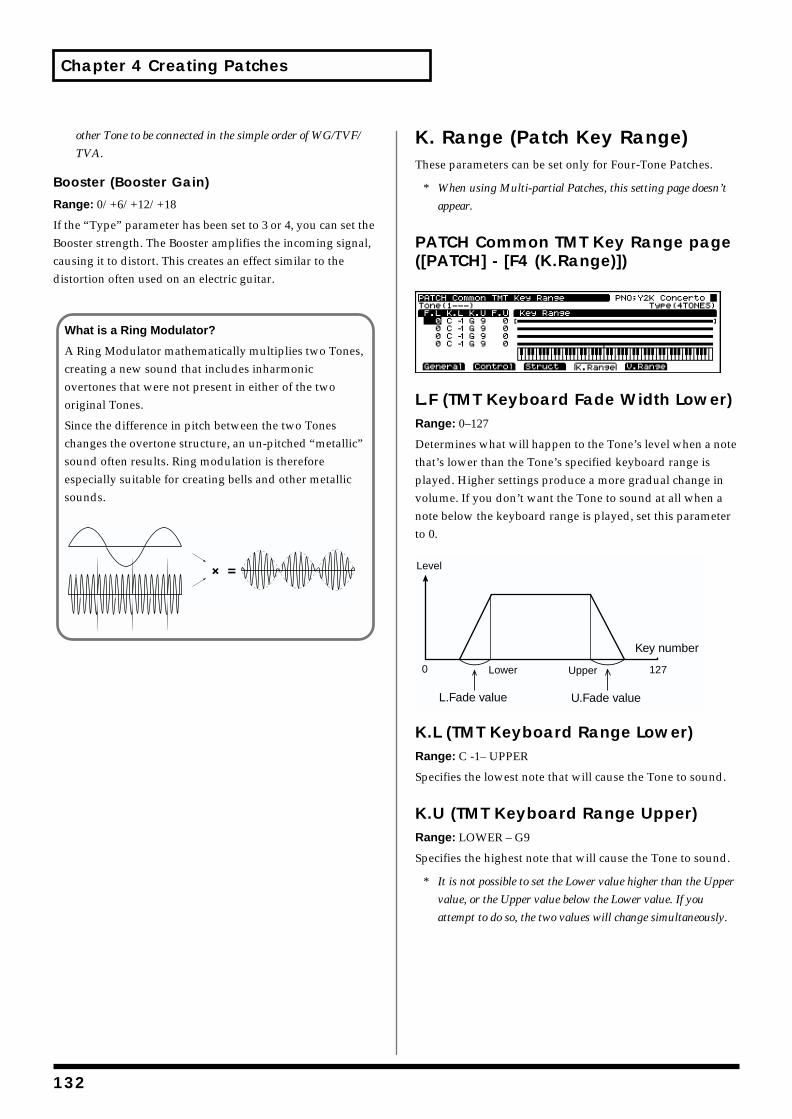
Chapter 4 Creating Patches
other Tone to be connected in the simple order of WG/TVF/
TVA.
Booster (Booster Gain)
Range: 0/+6/+12/+18
If the “Type” parameter has been set to 3 or 4, you can set the Booster strength. The Booster amplifies the incoming signal, causing it to distort. This creates an effect similar to the distortion often used on an electric guitar.
K. Range (Patch Key Range)These parameters can be set only for Four-Tone Patches.
* When using Multi-partial Patches, this setting page doesn’t
appear.
PATCH Common TMT Key Range page ([PATCH] - [F4 (K.Range)])fig.04-023.e_70
L.F (TMT Keyboard Fade Width Lower)Range: 0–127
Determines what will happen to the Tone’s level when a note that’s lower than the Tone’s specified keyboard range is played. Higher settings produce a more gradual change in volume. If you don’t want the Tone to sound at all when a note below the keyboard range is played, set this parameter to 0.fig.04-024.e
K.L (TMT Keyboard Range Lower)Range: C -1– UPPER
Specifies the lowest note that will cause the Tone to sound.
K.U (TMT Keyboard Range Upper)Range: LOWER – G9
Specifies the highest note that will cause the Tone to sound.
* It is not possible to set the Lower value higher than the Upper
value, or the Upper value below the Lower value. If you
attempt to do so, the two values will change simultaneously.
What is a Ring Modulator?
A Ring Modulator mathematically multiplies two Tones, creating a new sound that includes inharmonic overtones that were not present in either of the two original Tones.
Since the difference in pitch between the two Tones changes the overtone structure, an un-pitched “metallic” sound often results. Ring modulation is therefore especially suitable for creating bells and other metallic sounds.fig.04-022.e
L.Fade value U.Fade value
0 127
Level
UpperLower
Key number
132
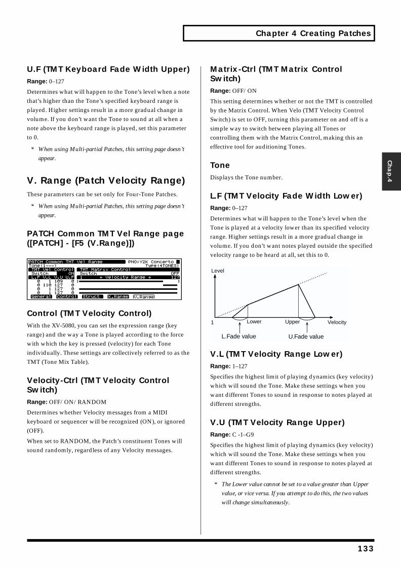
Chapter 4 Creating Patches
Chap.4
U.F (TMT Keyboard Fade Width Upper)Range: 0–127
Determines what will happen to the Tone’s level when a note that’s higher than the Tone’s specified keyboard range is played. Higher settings result in a more gradual change in volume. If you don’t want the Tone to sound at all when a note above the keyboard range is played, set this parameter to 0.
* When using Multi-partial Patches, this setting page doesn’t
appear.
V. Range (Patch Velocity Range)These parameters can be set only for Four-Tone Patches.
* When using Multi-partial Patches, this setting page doesn’t
appear.
PATCH Common TMT Vel Range page ([PATCH] - [F5 (V.Range)])fig.04-025.e_70
Control (TMT Velocity Control)With the XV-5080, you can set the expression range (key range) and the way a Tone is played according to the force with which the key is pressed (velocity) for each Tone individually. These settings are collectively referred to as the TMT (Tone Mix Table).
Velocity-Ctrl (TMT Velocity Control Switch)Range: OFF/ON/RANDOM
Determines whether Velocity messages from a MIDI keyboard or sequencer will be recognized (ON), or ignored (OFF).
When set to RANDOM, the Patch’s constituent Tones will sound randomly, regardless of any Velocity messages.
Matrix-Ctrl (TMT Matrix Control Switch)Range: OFF/ON
This setting determines whether or not the TMT is controlled by the Matrix Control. When Velo (TMT Velocity Control Switch) is set to OFF, turning this parameter on and off is a simple way to switch between playing all Tones or controlling them with the Matrix Control, making this an effective tool for auditioning Tones.
ToneDisplays the Tone number.
L.F (TMT Velocity Fade Width Lower)Range: 0–127
Determines what will happen to the Tone’s level when the Tone is played at a velocity lower than its specified velocity range. Higher settings result in a more gradual change in volume. If you don’t want notes played outside the specified velocity range to be heard at all, set this to 0.fig.04-026.e
V.L (TMT Velocity Range Lower)Range: 1–127
Specifies the highest limit of playing dynamics (key velocity) which will sound the Tone. Make these settings when you want different Tones to sound in response to notes played at different strengths.
V.U (TMT Velocity Range Upper)Range: C -1–G9
Specifies the highest limit of playing dynamics (key velocity) which will sound the Tone. Make these settings when you want different Tones to sound in response to notes played at different strengths.
* The Lower value cannot be set to a value greater than Upper
value, or vice versa. If you attempt to do this, the two values
will change simultaneously.
1
L.Fade value U.Fade value
Level
VelocityUpperLower
133
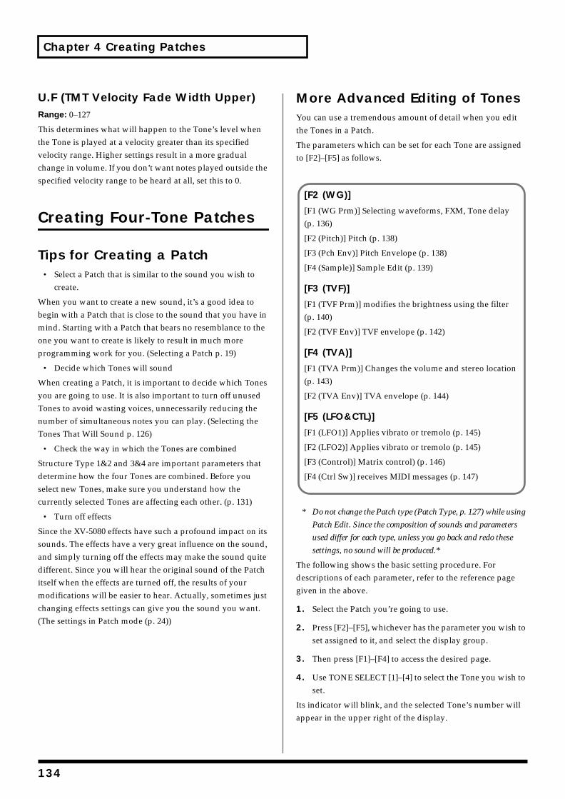
Chapter 4 Creating Patches
U.F (TMT Velocity Fade Width Upper)Range: 0–127
This determines what will happen to the Tone’s level when the Tone is played at a velocity greater than its specified velocity range. Higher settings result in a more gradual change in volume. If you don’t want notes played outside the specified velocity range to be heard at all, set this to 0.
Creating Four-Tone Patches
Tips for Creating a Patch• Select a Patch that is similar to the sound you wish to
create.
When you want to create a new sound, it’s a good idea to begin with a Patch that is close to the sound that you have in mind. Starting with a Patch that bears no resemblance to the one you want to create is likely to result in much more programming work for you. (Selecting a Patch p. 19)
• Decide which Tones will sound
When creating a Patch, it is important to decide which Tones you are going to use. It is also important to turn off unused Tones to avoid wasting voices, unnecessarily reducing the number of simultaneous notes you can play. (Selecting the Tones That Will Sound p. 126)
• Check the way in which the Tones are combined
Structure Type 1&2 and 3&4 are important parameters that determine how the four Tones are combined. Before you select new Tones, make sure you understand how the currently selected Tones are affecting each other. (p. 131)
• Turn off effects
Since the XV-5080 effects have such a profound impact on its sounds. The effects have a very great influence on the sound, and simply turning off the effects may make the sound quite different. Since you will hear the original sound of the Patch itself when the effects are turned off, the results of your modifications will be easier to hear. Actually, sometimes just changing effects settings can give you the sound you want. (The settings in Patch mode (p. 24))
More Advanced Editing of TonesYou can use a tremendous amount of detail when you edit the Tones in a Patch.
The parameters which can be set for each Tone are assigned to [F2]–[F5] as follows.
* Do not change the Patch type (Patch Type, p. 127) while using
Patch Edit. Since the composition of sounds and parameters
used differ for each type, unless you go back and redo these
settings, no sound will be produced.*
The following shows the basic setting procedure. For descriptions of each parameter, refer to the reference page given in the above.
1. Select the Patch you’re going to use.
2. Press [F2]–[F5], whichever has the parameter you wish to set assigned to it, and select the display group.
3. Then press [F1]–[F4] to access the desired page.
4. Use TONE SELECT [1]–[4] to select the Tone you wish to set.
Its indicator will blink, and the selected Tone’s number will appear in the upper right of the display.
[F2 (WG)]
[F1 (WG Prm)] Selecting waveforms, FXM, Tone delay (p. 136)
[F2 (Pitch)] Pitch (p. 138)
[F3 (Pch Env)] Pitch Envelope (p. 138)
[F4 (Sample)] Sample Edit (p. 139)
[F3 (TVF)]
[F1 (TVF Prm)] modifies the brightness using the filter (p. 140)
[F2 (TVF Env)] TVF envelope (p. 142)
[F4 (TVA)]
[F1 (TVA Prm)] Changes the volume and stereo location (p. 143)
[F2 (TVA Env)] TVA envelope (p. 144)
[F5 (LFO&CTL)]
[F1 (LFO1)] Applies vibrato or tremolo (p. 145)
[F2 (LFO2)] Applies vibrato or tremolo (p. 145)
[F3 (Control)] Matrix control) (p. 146)
[F4 (Ctrl Sw)] receives MIDI messages (p. 147)
134
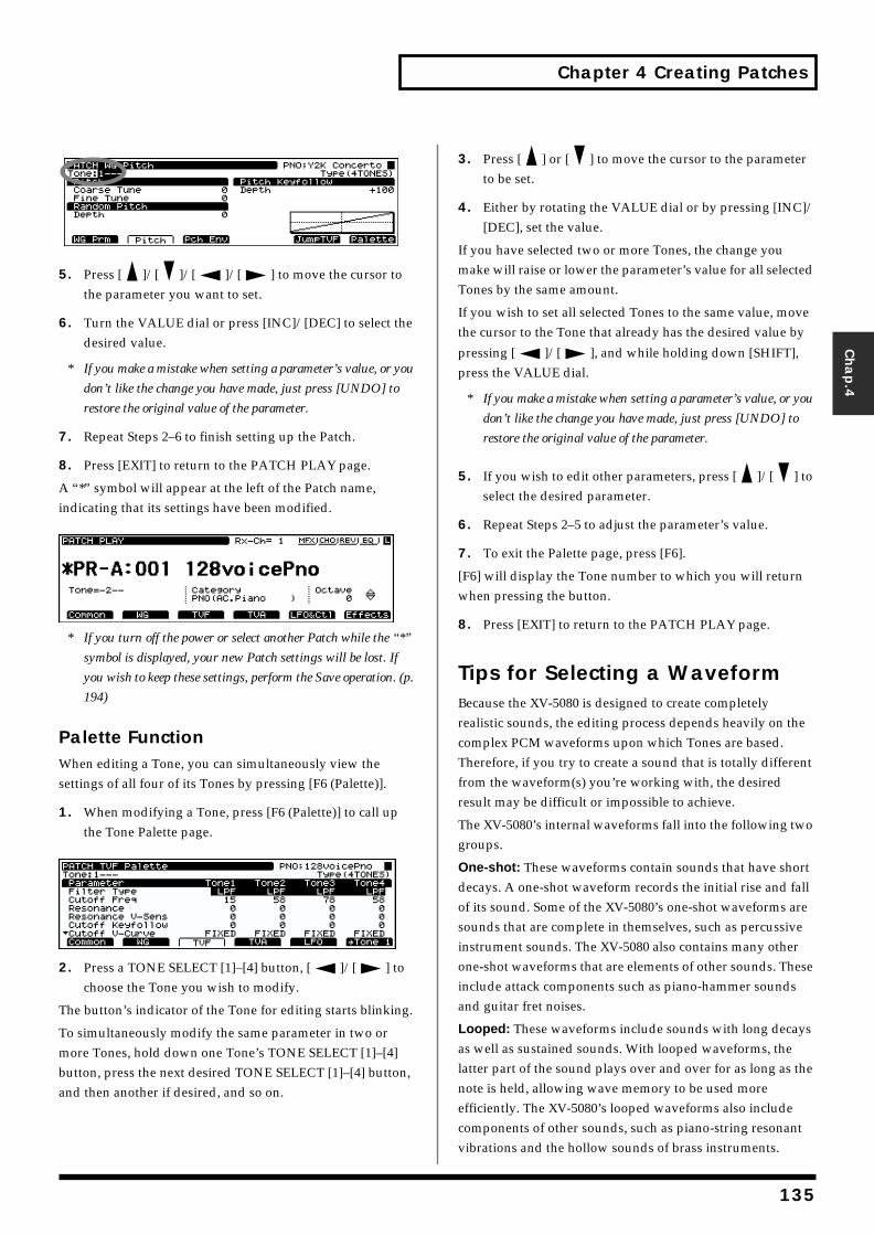
Chapter 4 Creating Patches
Chap.4
fig.04-027.e
5. Press [ ]/[ ]/[ ]/[ ] to move the cursor to the parameter you want to set.
6. Turn the VALUE dial or press [INC]/[DEC] to select the desired value.
* If you make a mistake when setting a parameter’s value, or you
don’t like the change you have made, just press [UNDO] to
restore the original value of the parameter.
7. Repeat Steps 2–6 to finish setting up the Patch.
8. Press [EXIT] to return to the PATCH PLAY page.
A “*” symbol will appear at the left of the Patch name, indicating that its settings have been modified.fig.04-028.e_70
* If you turn off the power or select another Patch while the “*”
symbol is displayed, your new Patch settings will be lost. If
you wish to keep these settings, perform the Save operation. (p.
194)
Palette FunctionWhen editing a Tone, you can simultaneously view the settings of all four of its Tones by pressing [F6 (Palette)].
1. When modifying a Tone, press [F6 (Palette)] to call up the Tone Palette page.
fig.04-029.e_70
2. Press a TONE SELECT [1]–[4] button, [ ]/[ ] to choose the Tone you wish to modify.
The button’s indicator of the Tone for editing starts blinking.
To simultaneously modify the same parameter in two or more Tones, hold down one Tone’s TONE SELECT [1]–[4] button, press the next desired TONE SELECT [1]–[4] button, and then another if desired, and so on.
3. Press [ ] or [ ] to move the cursor to the parameter to be set.
4. Either by rotating the VALUE dial or by pressing [INC]/[DEC], set the value.
If you have selected two or more Tones, the change you make will raise or lower the parameter’s value for all selected Tones by the same amount.
If you wish to set all selected Tones to the same value, move the cursor to the Tone that already has the desired value by
pressing [ ]/[ ], and while holding down [SHIFT], press the VALUE dial.
* If you make a mistake when setting a parameter’s value, or you
don’t like the change you have made, just press [UNDO] to
restore the original value of the parameter.
5. If you wish to edit other parameters, press [ ]/[ ] to select the desired parameter.
6. Repeat Steps 2–5 to adjust the parameter’s value.
7. To exit the Palette page, press [F6].
[F6] will display the Tone number to which you will return when pressing the button.
8. Press [EXIT] to return to the PATCH PLAY page.
Tips for Selecting a WaveformBecause the XV-5080 is designed to create completely realistic sounds, the editing process depends heavily on the complex PCM waveforms upon which Tones are based. Therefore, if you try to create a sound that is totally different from the waveform(s) you’re working with, the desired result may be difficult or impossible to achieve.
The XV-5080’s internal waveforms fall into the following two groups.
One-shot: These waveforms contain sounds that have short decays. A one-shot waveform records the initial rise and fall of its sound. Some of the XV-5080’s one-shot waveforms are sounds that are complete in themselves, such as percussive instrument sounds. The XV-5080 also contains many other one-shot waveforms that are elements of other sounds. These include attack components such as piano-hammer sounds and guitar fret noises.
Looped: These waveforms include sounds with long decays as well as sustained sounds. With looped waveforms, the latter part of the sound plays over and over for as long as the note is held, allowing wave memory to be used more efficiently. The XV-5080’s looped waveforms also include components of other sounds, such as piano-string resonant vibrations and the hollow sounds of brass instruments.
135

Chapter 4 Creating Patches
The following diagram shows an example of a sound – an electric organ – that combines one-shot and looped waveforms.fig.04-030.e
Notes for Editing One-Shot WaveformsYou cannot give a one-shot waveform a longer decay — or make it into a sustaining sound — by using an envelope. If you were to program such an envelope, you would be attempting to shape a portion of the sound that simply doesn’t exist, and the envelope would have no effect.
Notes for Editing Looped WaveformsWith many acoustic instruments such as piano and sax, extreme timbral changes occur during the first few moments of each note. This initial attack is what defines much of the instrument’s character. The XV-5080 provides a variety of waveforms containing realistic acoustic instrument attacks. To obtain the maximum realism when using these waveforms, it is best to leave the filter wide-open during the attack so that all of these important timbral changes are heard. If you use an envelope to modify the attack portion, you may not achieve the result you want. Use enveloping to produce the desired changes in the decay portion of the sound.fig.04-031.e
If you try to make a waveform’s attack brighter by lowering the high-frequency content of its decay using the TVF filter, consider the original timbral character of the waveform. If you’re making a part of the sound brighter than the original waveform, you should first generate new upper harmonics not present in the original waveform using the Color and Depth parameters (FXM parameter in the Patch WG Prm
page) before filtering. This will help you achieve the desired result. To make an entire waveform brighter, try applying effects such as an enhancer and equalizer before modifying the TVF parameter.
Modifying the Waveform and Pitch ([F2] (WG))This set of parameters allows you to select the PCM waveform that serves as the basis for the currently selected Tone, apply effects to the waveform, and control its pitch.
PATCH WG Parameter page ([PATCH] - [F2 (WG)] - [F1 (WG Prm)])fig.04-032.e_70
WAVE
Group (Wave Group)
Selects the group for the waveform that is to be the basis of the Tone.
Available Settings:
INT: Waveform stored in the XV-5080’s memory.
XP-A–H: Waveform on the wave expansion boards A–H.
* It is not possible to select XP-A–F unless a wave expansion
board is inserted into the corresponding slot.
SAMPLE: Samples (Wave data) loaded into the SIMM (memory module) from a sampler library or other source.
L (Wave Number L)
Range: 1–1083
Selects the desired waveform by its number.
The name of the wave will be displayed in square brackets [ ].
R (Wave Number R)
Range: 1–1083
Selects the desired waveform by its number.
The name of the wave will be displayed in square brackets [ ].
* When Wave Number R is set to "----," the tone being edited
goes to MONO.
* By holding down [SHIFT] and pressing [F6], you can rapidly
switch between STEREO and MONO tones.
TVA ENV for looped Organ waveform (sustain portion)
Key-off
Resulting TVA ENV changeTVA ENV for one-shot Key-click waveform (attack portion)
Key-off
+ =
Tone change stored with the wave
Envelope for the TVF filter
Resulting tone change
Looped Portion
136

Chapter 4 Creating Patches
Chap.4
Gain (Wave Gain)
Range: -6/0/+6/+12
Specifies the gain (amplitude) of the waveform. The value changes in 6 dB (decibel) steps—an increase of 6 dB doubles the waveform’s gain. If you intend to use the Booster to distort the waveform’s sound, set this parameter to its maximum value.
Tempo Sync (Wave Tempo Sync)
Range: ON/OFF
Determines whether the waveform is synchronized (ON) or not synchronized (OFF) to the Patch’s tempo.
FXM (Frequency Cross Modulation)FXM (Frequency Cross Modulation) uses a specified waveform to apply frequency modulation to the currently selected waveform, creating complex overtones. This can be useful when creating wilder sounds or sound effects.
Switch (Wave FXM Switch)
Range: ON/OFF
Sets whether FXM will be used (ON) or not (OFF).
Color (Wave FXM Color)
Range: 1–4
Specifies how FXM will perform its frequency modulation. Higher settings result in a grainier sound, while lower settings result in a more metallic sound.
Depth (Wave FXM Depth)
Range: 0–16
Specifies the depth of the modulation produced by FXM.
Tone DelayProduces a time delay between the moment a key is pressed (or released) and the moment the Tone actually begins to sound. Since you can adjust the timing of each Tone in a Patch, you can create effects in which pressing a single key produces two or more sounds occurring at different times.
If you do not wish to use Tone Delay, set Mode to NORMAL and Delay Time to 0.
Mode (Tone Delay Mode)
Sets the manner in which the Tone will sound.
Available Settings:
NORMAL: The Tone will sound after the specified Delay Time.
fig.04-033.e
HOLD: The Tone will only sound if the key is held for longer than the specified Delay Time. If the key is released before the Delay Time has elapsed, the Tone will not sound.fig.04-034.e
KEY-OFF-NORMAL: The Tone will not sound while the key is being pressed, but will sound — after the specified Delay Time — when the key is released.fig.04-035.e
KEY-OFF-DECAY: The Tone will not sound while the key is being pressed, but will sound after the specified Delay Time when the key is released. However, for this setting — unlike KEY-OFF-N — the TVA envelope of the Tone will begin when the key is first pressed. As a result, in most cases, only the decay portion of the sound will be heard.fig.04-036.e
If you have selected a Wave that is a decay-type sound (i.e., a sound that fades away naturally even if the key is not released), selecting KEY-OFF-NORMAL or KEY-OFF-DECAY may result in no sound being heard.
Note off
Delay time
Note on
NORMAL
Note off
Delay time
Note on
HOLD
No soundplayed
Note off
Delay time
Note on
KEY-OFF-NORMAL
Note off
Delay time
Note on
KEY-OFF-DECAY
137
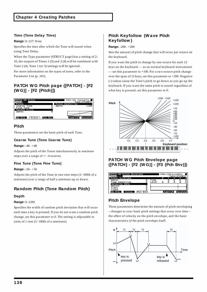
Chapter 4 Creating Patches
Time (Tone Delay Time)
Range: 0–127/Note
Specifies the time after which the Tone will sound when using Tone Delay.
When the Type parameter (STRUCT page) has a setting of 2–10, the outputs of Tones 1 (3) and 2 (4) will be combined with Tone 2 (4). Tone 1 (or 3) settings will be ignored.
For more information on the types of notes, refer to the Parameter List (p. 241).
PATCH WG Pitch page ([PATCH] - [F2 (WG)] - [F2 (Pitch)])fig.04-037.e_70
PitchThese parameters set the basic pitch of each Tone.
Coarse Tune (Tone Coarse Tune)
Range: -48– +48
Adjusts the pitch of the Tones simultaneously in semitone steps over a range of +/-4 octaves.
Fine Tune (Tone Fine Tune)
Range: -50– +50
Adjusts the pitch of the Tone in one-cent steps (1/100th of a semitone) over a range of half a semitone up or down.
Random Pitch (Tone Random Pitch)
Depth
Range: 0–1200
Specifies the width of random pitch deviation that will occur each time a key is pressed. If you do not want a random pitch change, set this parameter to 0. The setting is adjustable in units of 1 cent (1/100th of a semitone).
Pitch Keyfollow (Wave Pitch Keyfollow)Range: -200– +200
Sets the amount of pitch change that will occur per octave on the keyboard.
If you want the pitch to change by one octave for each 12 keys on the keyboard — as on normal keyboard instruments — set this parameter to +100. For a two-octave pitch change over the span of 12 keys, set this parameter to +200. Negative (-) values cause the Tone’s pitch to go down as you go up the keyboard. If you want the same pitch to sound regardless of what key is pressed, set this parameter to 0.fig.04-038.e
PATCH WG Pitch Envelope page ([PATCH] - [F2 (WG)] - [F3 (Pch Env)])fig.04-039.e_70
Pitch EnvelopeThese parameters determine the amount of pitch enveloping – changes to your basic pitch settings that occur over time – the effect of velocity on the pitch envelope, and the basic characteristics of the pitch envelope itself.fig.04-040.e
C2 C3 C4 C5 C6 C7
–100–70–50–30
–100+10+20+30+40+50+70
+100
+120+150+200
Pitch
Keyboard position
T1 T2 T3 T4
L3
L4L2
L1
L0
Pitch
key ispressed
key isreleased
Time
138
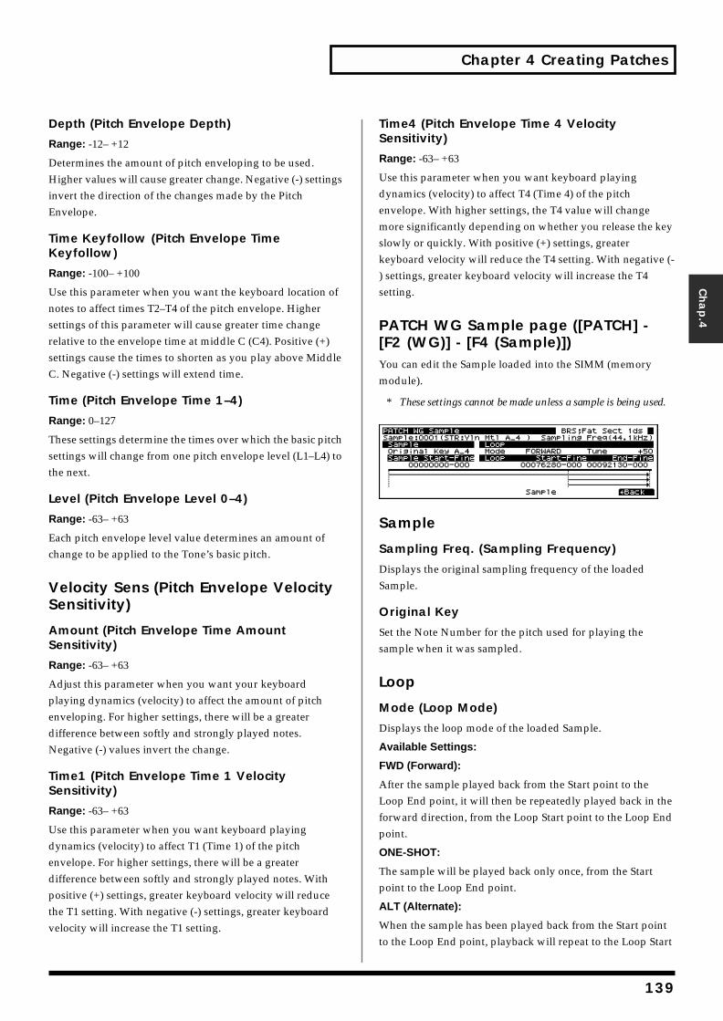
Chapter 4 Creating Patches
Chap.4
Depth (Pitch Envelope Depth)
Range: -12– +12
Determines the amount of pitch enveloping to be used. Higher values will cause greater change. Negative (-) settings invert the direction of the changes made by the Pitch Envelope.
Time Keyfollow (Pitch Envelope Time Keyfollow)
Range: -100– +100
Use this parameter when you want the keyboard location of notes to affect times T2–T4 of the pitch envelope. Higher settings of this parameter will cause greater time change relative to the envelope time at middle C (C4). Positive (+) settings cause the times to shorten as you play above Middle C. Negative (-) settings will extend time.
Time (Pitch Envelope Time 1–4)
Range: 0–127
These settings determine the times over which the basic pitch settings will change from one pitch envelope level (L1–L4) to the next.
Level (Pitch Envelope Level 0–4)
Range: -63– +63
Each pitch envelope level value determines an amount of change to be applied to the Tone’s basic pitch.
Velocity Sens (Pitch Envelope Velocity Sensitivity)
Amount (Pitch Envelope Time Amount Sensitivity)
Range: -63– +63
Adjust this parameter when you want your keyboard playing dynamics (velocity) to affect the amount of pitch enveloping. For higher settings, there will be a greater difference between softly and strongly played notes. Negative (-) values invert the change.
Time1 (Pitch Envelope Time 1 Velocity Sensitivity)
Range: -63– +63
Use this parameter when you want keyboard playing dynamics (velocity) to affect T1 (Time 1) of the pitch envelope. For higher settings, there will be a greater difference between softly and strongly played notes. With positive (+) settings, greater keyboard velocity will reduce the T1 setting. With negative (-) settings, greater keyboard velocity will increase the T1 setting.
Time4 (Pitch Envelope Time 4 Velocity Sensitivity)
Range: -63– +63
Use this parameter when you want keyboard playing dynamics (velocity) to affect T4 (Time 4) of the pitch envelope. With higher settings, the T4 value will change more significantly depending on whether you release the key slowly or quickly. With positive (+) settings, greater keyboard velocity will reduce the T4 setting. With negative (-) settings, greater keyboard velocity will increase the T4 setting.
PATCH WG Sample page ([PATCH] - [F2 (WG)] - [F4 (Sample)])You can edit the Sample loaded into the SIMM (memory module).
* These settings cannot be made unless a sample is being used.fig.04-041.e_70
Sample
Sampling Freq. (Sampling Frequency)
Displays the original sampling frequency of the loaded Sample.
Original Key
Set the Note Number for the pitch used for playing the sample when it was sampled.
Loop
Mode (Loop Mode)
Displays the loop mode of the loaded Sample.
Available Settings:
FWD (Forward):
After the sample played back from the Start point to the Loop End point, it will then be repeatedly played back in the forward direction, from the Loop Start point to the Loop End point.
ONE-SHOT:
The sample will be played back only once, from the Start point to the Loop End point.
ALT (Alternate):
When the sample has been played back from the Start point to the Loop End point, playback will repeat to the Loop Start
139
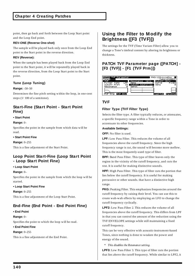
Chapter 4 Creating Patches
point, then go back and forth between the Loop Start point and the Loop End point.
REV-ONE (Reverse One-shot)
The sample will be played back only once from the Loop End point to the Start point in the reverse direction.
REV (Reverse):
When the sample has been played back from the Loop End point to the Start point, it will be repeatedly played back in the reverse direction, from the Loop Start point to the Start point.
Tune (Loop Tuning)
Range: -50–50
Determines the fine pitch setting within the loop, in one-cent steps (1/100 of a semitone).
Start-Fine (Start Point - Start Point Fine)• Start Point
Range: 0–
Specifies the point in the sample from which data will be read.
• Start Point Fine
Range: 0–255
This is a fine adjustment of the Start Point.
Loop Point Start-Fine (Loop Start Point - Loop Start Point Fine)• Loop Start Point
Range: 0–
Specifies the point in the sample from which the loop will be started.
• Loop Start Point Fine
Range: 0–255
This is a fine adjustment of the Loop Start Point.
End-Fine (End Point - End Point Fine)• End Point
Range: 0–
Specifies the point to which the loop will be read.
• End Point Fine
Range: 0–255
This is a fine adjustment of the End Point.
Using the Filter to Modify the Brightness ([F3 (TVF)])The settings for the TVF (Time Variant Filter) allow you to change a Tone’s timbral content by altering its brightness or thickness.
PATCH TVF Parameter page ([PATCH] - [F3 (TVF)] - [F1 (TVF Prm)])fig.04-042.e_70
TVF
Filter Type (TVF Filter Type)
Selects the filter type. A filter typically reduces, or attenuates, a specific frequency range within a Tone in order to accentuate its other frequencies.
Available Settings:
OFF: No filter is used.
LPF: Low Pass Filter. This reduces the volume of all frequencies above the cutoff frequency. Since the high frequency range is cut, the sound will become more mellow. This is the most frequently-used type of filter.
BPF: Band Pass Filter. This type of filter leaves only the region in the vicinity of the cutoff frequency, and cuts the rest. It is useful for making distinctive sounds.
HPF: High Pass Filter. This type of filter cuts the portion that lies below the cutoff frequency. It is useful for making percussive or other sounds. that have a distinctive high range.
PKG: Peaking Filter. This emphasizes frequencies around the cutoff frequency by raising their level. You can use this to create wah-wah effects by employing an LFO to change the cutoff frequency cyclically.
LPF2: Low Pass Filter 2. This reduces the volume of all frequencies above the cutoff frequency. This differs from LPF in that you can control the amount of the reduction using the TVF ENVELOPE settings while still maintaining a fixed cutoff frequency.
This can be very effective with acoustic-instrument-based Tones, since nothing is done to weaken the power and energy of the sound.
* This disables the Resonance setting.
LPF3: Low Pass Filter 3. This type of filter cuts the portion that lies above the cutoff frequency. While similar to LPF2, it
140
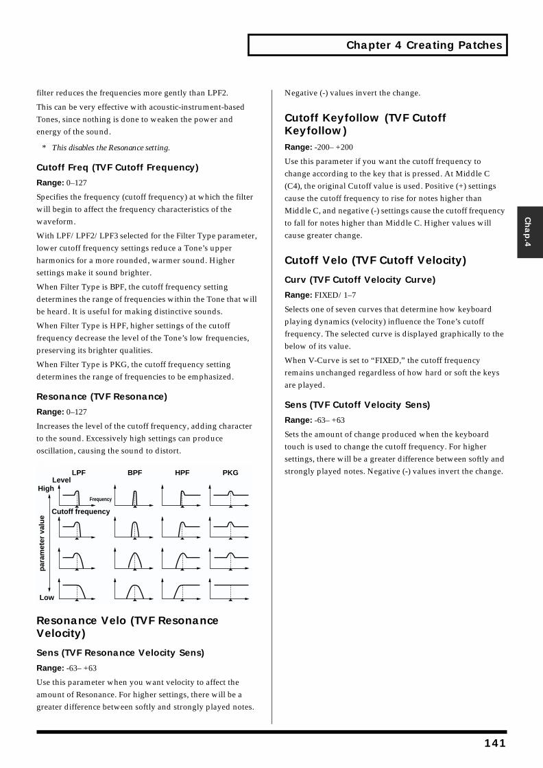
Chapter 4 Creating Patches
Chap.4
filter reduces the frequencies more gently than LPF2.
This can be very effective with acoustic-instrument-based Tones, since nothing is done to weaken the power and energy of the sound.
* This disables the Resonance setting.
Cutoff Freq (TVF Cutoff Frequency)
Range: 0–127
Specifies the frequency (cutoff frequency) at which the filter will begin to affect the frequency characteristics of the waveform.
With LPF/LPF2/LPF3 selected for the Filter Type parameter, lower cutoff frequency settings reduce a Tone’s upper harmonics for a more rounded, warmer sound. Higher settings make it sound brighter.
When Filter Type is BPF, the cutoff frequency setting determines the range of frequencies within the Tone that will be heard. It is useful for making distinctive sounds.
When Filter Type is HPF, higher settings of the cutoff frequency decrease the level of the Tone’s low frequencies, preserving its brighter qualities.
When Filter Type is PKG, the cutoff frequency setting determines the range of frequencies to be emphasized.
Resonance (TVF Resonance)
Range: 0–127
Increases the level of the cutoff frequency, adding character to the sound. Excessively high settings can produce oscillation, causing the sound to distort.fig.04-043.e
Resonance Velo (TVF Resonance Velocity)
Sens (TVF Resonance Velocity Sens)
Range: -63– +63
Use this parameter when you want velocity to affect the amount of Resonance. For higher settings, there will be a greater difference between softly and strongly played notes.
Negative (-) values invert the change.
Cutoff Keyfollow (TVF Cutoff Keyfollow)Range: -200– +200
Use this parameter if you want the cutoff frequency to change according to the key that is pressed. At Middle C (C4), the original Cutoff value is used. Positive (+) settings cause the cutoff frequency to rise for notes higher than Middle C, and negative (-) settings cause the cutoff frequency to fall for notes higher than Middle C. Higher values will cause greater change.
Cutoff Velo (TVF Cutoff Velocity)
Curv (TVF Cutoff Velocity Curve)
Range: FIXED/1–7
Selects one of seven curves that determine how keyboard playing dynamics (velocity) influence the Tone’s cutoff frequency. The selected curve is displayed graphically to the below of its value.
When V-Curve is set to “FIXED,” the cutoff frequency remains unchanged regardless of how hard or soft the keys are played.
Sens (TVF Cutoff Velocity Sens)
Range: -63– +63
Sets the amount of change produced when the keyboard touch is used to change the cutoff frequency. For higher settings, there will be a greater difference between softly and strongly played notes. Negative (-) values invert the change.LPF BPF HPF PKG
par
amet
er v
alu
e
Level
Cutoff frequency
Frequency
High
Low
141

Chapter 4 Creating Patches
PATCH TVF Envelope page ([PATCH] - [F3 (TVF)] - [F2 (TVF Env)])fig.04-044.e_70
TVF EnvelopeThese parameters determine the amount of filter enveloping – changes to your original cutoff frequency setting that occur over time – the effect of velocity on the TVF envelope, and the basic characteristics of the TVF envelope itself.fig.04-045.e
Depth (TVF Envelope Depth)
Range: -63– +63
Adjusts the amount of filter enveloping. Higher values will cause greater change. Negative (-) values invert the effect of the TVF envelope.
Time Keyfollow (TVF Envelope Time Keyfollow)
Range: -100– +100
Use this parameter when you want a note’s keyboard position to affect times T2–T4 of the TVF envelope. Higher settings change the times by a greater amount as you move away from Middle C (C4) — at Middle C, the original T1–T4 settings are in effect. Positive (+) settings cause the times to shorten as you play above Middle C. Negative (-) settings will extend time.
Time1–4 (TVF Envelope Time 1–4)
Range: 0–127
These settings determine the times over which the cutoff frequency setting will change from one TVF envelope level (L1–L4) to the next.
Level1–4 (TVF Envelope Level 1–4)
Range: 0–127
Each TVF envelope level value determines an amount of change to be applied to the original cutoff frequency setting.
Velo Sens (TVF Envelope Velocity Sensitivity)
Amount (TVF Envelope Velocity Sensitivity)
Range: -63– +63
Use this parameter when you want keyboard playing dynamics (velocity) to affect the depth of the TVF envelope. For higher settings, there will be a greater difference between softly and strongly played notes. Negative (-) values invert the change.
Time1 (TVF Envelope Time 1 Velocity Sensitivity)
Range: -63– +63
Use this parameter when you want keyboard playing dynamics (velocity) to affect T1 (Time 1) of the TVF envelope. For higher settings, there will be a greater difference between softly and strongly played notes. With positive (+) settings, greater keyboard velocity will reduce the T1 setting. With negative (-) settings, greater keyboard velocity will increase the T1 setting.
Time4 (TVF Envelope Time 4 Velocity Sensitivity)
Range: -63– +63
Use this parameter when you want keyboard playing dynamics (velocity) to affect T4 (Time 4) of the TVF envelope. With higher settings, the T4 value will change more significantly depending on whether you release the key slowly or quickly. With positive (+) settings, greater keyboard velocity will reduce the T4 setting. With negative (-) settings, greater keyboard velocity will increase the T4 setting.
Velo Curve (TVF Envelope Velocity Curve)Range: FIXED/1–7
This selects one of seven velocity curves that determine how velocity will affect the depth of the TVF Envelope. The selected curve is displayed graphically to the right of its value.
T1 T2 T3 T4
L3
L1
L2
L4
L0
CutoffFrequency
Timekey ispressed
key isreleased
142
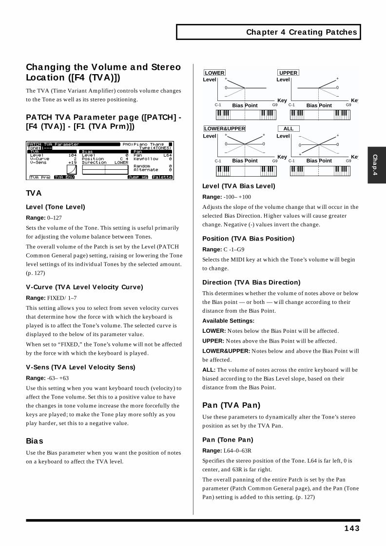
Chapter 4 Creating Patches
Chap.4
Changing the Volume and Stereo Location ([F4 (TVA)])The TVA (Time Variant Amplifier) controls volume changes to the Tone as well as its stereo positioning.
PATCH TVA Parameter page ([PATCH] - [F4 (TVA)] - [F1 (TVA Prm)])fig.04-046.e_70
TVA
Level (Tone Level)
Range: 0–127
Sets the volume of the Tone. This setting is useful primarily for adjusting the volume balance between Tones.
The overall volume of the Patch is set by the Level (PATCH Common General page) setting, raising or lowering the Tone level settings of its individual Tones by the selected amount. (p. 127)
V-Curve (TVA Level Velocity Curve)
Range: FIXED/1–7
This setting allows you to select from seven velocity curves that determine how the force with which the keyboard is played is to affect the Tone’s volume. The selected curve is displayed to the below of its parameter value.
When set to “FIXED,” the Tone’s volume will not be affected by the force with which the keyboard is played.
V-Sens (TVA Level Velocity Sens)
Range: -63– +63
Use this setting when you want keyboard touch (velocity) to affect the Tone volume. Set this to a positive value to have the changes in tone volume increase the more forcefully the keys are played; to make the Tone play more softly as you play harder, set this to a negative value.
BiasUse the Bias parameter when you want the position of notes on a keyboard to affect the TVA level.
fig.04-047.e
Level (TVA Bias Level)
Range: -100– +100
Adjusts the slope of the volume change that will occur in the selected Bias Direction. Higher values will cause greater change. Negative (-) values invert the change.
Position (TVA Bias Position)
Range: C -1–G9
Selects the MIDI key at which the Tone’s volume will begin to change.
Direction (TVA Bias Direction)
This determines whether the volume of notes above or below the Bias point — or both — will change according to their distance from the Bias Point.
Available Settings:
LOWER: Notes below the Bias Point will be affected.
UPPER: Notes above the Bias Point will be affected.
LOWER&UPPER: Notes below and above the Bias Point will be affected.
ALL: The volume of notes across the entire keyboard will be biased according to the Bias Level slope, based on their distance from the Bias Point.
Pan (TVA Pan)Use these parameters to dynamically alter the Tone’s stereo position as set by the TVA Pan.
Pan (Tone Pan)
Range: L64–0–63R
Specifies the stereo position of the Tone. L64 is far left, 0 is center, and 63R is far right.
The overall panning of the entire Patch is set by the Pan parameter (Patch Common General page), and the Pan (Tone Pan) setting is added to this setting. (p. 127)
C-1 G9
+
0
–
C-1 G9
+
0
–
C-1 G9
+
0
–
C-1 G9
+
0
–
+
0
– +
0
–LOWER&UPPER
LOWER UPPER
ALL
Bias Point
Level
Level
Level
Level
Key
Key
Key
KeyBias Point
Bias Point
Bias Point
143
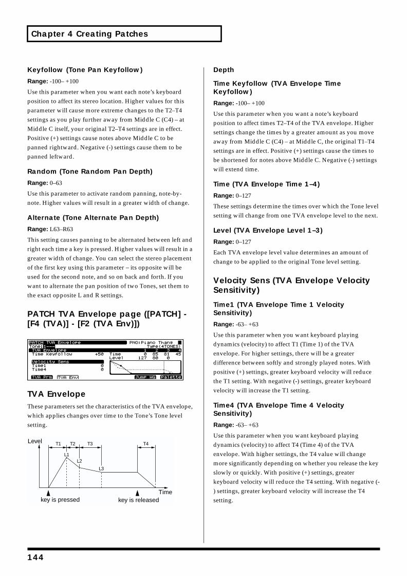
Chapter 4 Creating Patches
Keyfollow (Tone Pan Keyfollow)
Range: -100– +100
Use this parameter when you want each note’s keyboard position to affect its stereo location. Higher values for this parameter will cause more extreme changes to the T2–T4 settings as you play further away from Middle C (C4) – at Middle C itself, your original T2–T4 settings are in effect. Positive (+) settings cause notes above Middle C to be panned rightward. Negative (-) settings cause them to be panned leftward.
Random (Tone Random Pan Depth)
Range: 0–63
Use this parameter to activate random panning, note-by-note. Higher values will result in a greater width of change.
Alternate (Tone Alternate Pan Depth)
Range: L63–R63
This setting causes panning to be alternated between left and right each time a key is pressed. Higher values will result in a greater width of change. You can select the stereo placement of the first key using this parameter – its opposite will be used for the second note, and so on back and forth. If you want to alternate the pan position of two Tones, set them to the exact opposite L and R settings.
PATCH TVA Envelope page ([PATCH] - [F4 (TVA)] - [F2 (TVA Env)])fig.04-048.e_70
TVA EnvelopeThese parameters set the characteristics of the TVA envelope, which applies changes over time to the Tone’s Tone level setting.fig.04-049.e
Depth
Time Keyfollow (TVA Envelope Time Keyfollow)
Range: -100– +100
Use this parameter when you want a note’s keyboard position to affect times T2–T4 of the TVA envelope. Higher settings change the times by a greater amount as you move away from Middle C (C4) – at Middle C, the original T1–T4 settings are in effect. Positive (+) settings cause the times to be shortened for notes above Middle C. Negative (-) settings will extend time.
Time (TVA Envelope Time 1–4)
Range: 0–127
These settings determine the times over which the Tone level setting will change from one TVA envelope level to the next.
Level (TVA Envelope Level 1–3)
Range: 0–127
Each TVA envelope level value determines an amount of change to be applied to the original Tone level setting.
Velocity Sens (TVA Envelope Velocity Sensitivity)
Time1 (TVA Envelope Time 1 Velocity Sensitivity)
Range: -63– +63
Use this parameter when you want keyboard playing dynamics (velocity) to affect T1 (Time 1) of the TVA envelope. For higher settings, there will be a greater difference between softly and strongly played notes. With positive (+) settings, greater keyboard velocity will reduce the T1 setting. With negative (-) settings, greater keyboard velocity will increase the T1 setting.
Time4 (TVA Envelope Time 4 Velocity Sensitivity)
Range: -63– +63
Use this parameter when you want keyboard playing dynamics (velocity) to affect T4 (Time 4) of the TVA envelope. With higher settings, the T4 value will change more significantly depending on whether you release the key slowly or quickly. With positive (+) settings, greater keyboard velocity will reduce the T4 setting. With negative (-) settings, greater keyboard velocity will increase the T4 setting.
T1 T2 T3 T4
L3
L1L2
Level
key is pressed key is releasedTime
144
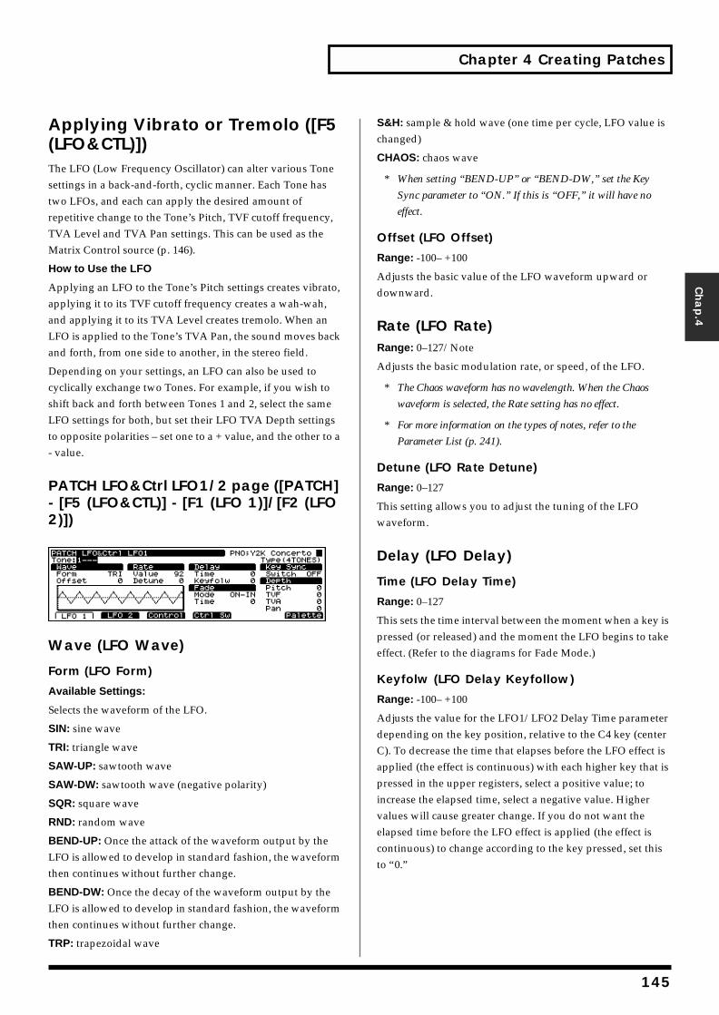
Chapter 4 Creating Patches
Chap.4
Applying Vibrato or Tremolo ([F5 (LFO&CTL)])The LFO (Low Frequency Oscillator) can alter various Tone settings in a back-and-forth, cyclic manner. Each Tone has two LFOs, and each can apply the desired amount of repetitive change to the Tone’s Pitch, TVF cutoff frequency, TVA Level and TVA Pan settings. This can be used as the Matrix Control source (p. 146).
How to Use the LFO
Applying an LFO to the Tone’s Pitch settings creates vibrato, applying it to its TVF cutoff frequency creates a wah-wah, and applying it to its TVA Level creates tremolo. When an LFO is applied to the Tone’s TVA Pan, the sound moves back and forth, from one side to another, in the stereo field.
Depending on your settings, an LFO can also be used to cyclically exchange two Tones. For example, if you wish to shift back and forth between Tones 1 and 2, select the same LFO settings for both, but set their LFO TVA Depth settings to opposite polarities – set one to a + value, and the other to a - value.
PATCH LFO&Ctrl LFO1/2 page ([PATCH] - [F5 (LFO&CTL)] - [F1 (LFO 1)]/[F2 (LFO 2)])fig.04-050.e_70
Wave (LFO Wave)
Form (LFO Form)
Available Settings:
Selects the waveform of the LFO.
SIN: sine wave
TRI: triangle wave
SAW-UP: sawtooth wave
SAW-DW: sawtooth wave (negative polarity)
SQR: square wave
RND: random wave
BEND-UP: Once the attack of the waveform output by the LFO is allowed to develop in standard fashion, the waveform then continues without further change.
BEND-DW: Once the decay of the waveform output by the LFO is allowed to develop in standard fashion, the waveform then continues without further change.
TRP: trapezoidal wave
S&H: sample & hold wave (one time per cycle, LFO value is changed)
CHAOS: chaos wave
* When setting “BEND-UP” or “BEND-DW,” set the Key
Sync parameter to “ON.” If this is “OFF,” it will have no
effect.
Offset (LFO Offset)
Range: -100– +100
Adjusts the basic value of the LFO waveform upward or downward.
Rate (LFO Rate)Range: 0–127/Note
Adjusts the basic modulation rate, or speed, of the LFO.
* The Chaos waveform has no wavelength. When the Chaos
waveform is selected, the Rate setting has no effect.
* For more information on the types of notes, refer to the
Parameter List (p. 241).
Detune (LFO Rate Detune)
Range: 0–127
This setting allows you to adjust the tuning of the LFO waveform.
Delay (LFO Delay)
Time (LFO Delay Time)
Range: 0–127
This sets the time interval between the moment when a key is pressed (or released) and the moment the LFO begins to take effect. (Refer to the diagrams for Fade Mode.)
Keyfolw (LFO Delay Keyfollow)
Range: -100– +100
Adjusts the value for the LFO1/LFO2 Delay Time parameter depending on the key position, relative to the C4 key (center C). To decrease the time that elapses before the LFO effect is applied (the effect is continuous) with each higher key that is pressed in the upper registers, select a positive value; to increase the elapsed time, select a negative value. Higher values will cause greater change. If you do not want the elapsed time before the LFO effect is applied (the effect is continuous) to change according to the key pressed, set this to “0.”
145
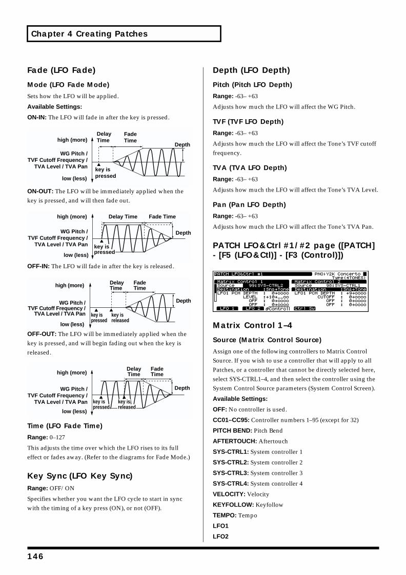
Chapter 4 Creating Patches
Fade (LFO Fade)
Mode (LFO Fade Mode)
Sets how the LFO will be applied.
Available Settings:
ON-IN: The LFO will fade in after the key is pressed.fig.04-051.e
ON-OUT: The LFO will be immediately applied when the key is pressed, and will then fade out.fig.04-052.e
OFF-IN: The LFO will fade in after the key is released.fig.04-053.e
OFF-OUT: The LFO will be immediately applied when the key is pressed, and will begin fading out when the key is released.fig.04-054.e
Time (LFO Fade Time)
Range: 0–127
This adjusts the time over which the LFO rises to its full effect or fades away. (Refer to the diagrams for Fade Mode.)
Key Sync (LFO Key Sync)Range: OFF/ON
Specifies whether you want the LFO cycle to start in sync with the timing of a key press (ON), or not (OFF).
Depth (LFO Depth)
Pitch (Pitch LFO Depth)
Range: -63– +63
Adjusts how much the LFO will affect the WG Pitch.
TVF (TVF LFO Depth)
Range: -63– +63
Adjusts how much the LFO will affect the Tone’s TVF cutoff frequency.
TVA (TVA LFO Depth)
Range: -63– +63
Adjusts how much the LFO will affect the Tone’s TVA Level.
Pan (Pan LFO Depth)
Range: -63– +63
Adjusts how much the LFO will affect the Tone’s TVA Pan.
PATCH LFO&Ctrl #1/#2 page ([PATCH] - [F5 (LFO&Ctl)] - [F3 (Control)])fig.04-055.e_70
Matrix Control 1–4
Source (Matrix Control Source)
Assign one of the following controllers to Matrix Control Source. If you wish to use a controller that will apply to all Patches, or a controller that cannot be directly selected here, select SYS-CTRL1–4, and then select the controller using the System Control Source parameters (System Control Screen).
Available Settings:
OFF: No controller is used.
CC01–CC95: Controller numbers 1–95 (except for 32)
PITCH BEND: Pitch Bend
AFTERTOUCH: Aftertouch
SYS-CTRL1: System controller 1
SYS-CTRL2: System controller 2
SYS-CTRL3: System controller 3
SYS-CTRL4: System controller 4
VELOCITY: Velocity
KEYFOLLOW: Keyfollow
TEMPO: Tempo
LFO1
LFO2
key ispressed
high (more)
low (less)
WG Pitch /TVF Cutoff Frequency /
TVA Level / TVA Pan
DelayTime
FadeTime
Depth
key ispressed
high (more)
low (less)
WG Pitch /TVF Cutoff Frequency /
TVA Level / TVA Pan
Delay Time Fade Time
Depth
high (more)
low (less)
WG Pitch /TVF Cutoff Frequency /
TVA Level / TVA Pan
DelayTime
FadeTime
Depth
key ispressed
key isreleased
key ispressed
high (more)
low (less)
WG Pitch /TVF Cutoff Frequency /
TVA Level / TVA Pan
DelayTime
FadeTime
Depth
key isreleased
146

Chapter 4 Creating Patches
Chap.4
PITCH ENV: Pitch envelope
TVF ENV: TVF envelope
TVA ENV: TVA envelope
Destination
Selects the parameters to be controlled. (p. 218)
Sens (Sensitivity)
Range: -63– +63
Adjusts the amount of change that will occur in response to controller changes. Negative (-) values invert the change. Negative (-) settings will invert the phase. For LFO rates, negative (-) values slow down the LFO, and positive (+) values will speed it up.
Tone
Selects the Tone to which the two previous parameter settings are applied. “o” turns signifies that the Tone is selected for control, “_” that it is not selected, and “R” that the change being applied is inverted when applied to this Tone.
PATCH LFO&Ctrl Control Sw page ([PATCH] - [F5 (LFO&CTL)] - [F4 (Ctrl Sw)])fig.04-056.e_70
MIDI Rx Switch (MIDI Receive Switch)
Bender Sw (Tone Receive Bender)
Range: OFF/ON
If you want the Tone to respond to Pitch Bend messages, turn this parameter on. If not, turn it off.
Expression Sw (Tone Receive Expression)
Range: OFF/ON
If you want the Tone to respond to Expression messages, turn this on. If not, turn it off.
Hold-1 Sw (Tone Receive Hold 1)
Range: OFF/ON
Set this to ON if you wish the tone to respond to Hold1 messages – these messages cause sounds to continue playing when a sustain/damper pedal is pressed. Set this to OFF when you do not want the Tone to respond to Hold1 messages.
Redamper (Tone Redamper Switch)
Range: OFF/ON
If a Hold 1 message is received during the time between a note-off – when you release the key – and the time at which the note actually disappears, any currently sounding notes will be sustained if Redamper is set to ON. To take advantage of this feature, you must also turn on the Tone Receive Hold 1 setting.
Pan Mode (Tone Receive Pan Mode)
Available Settings:
CONT: Pan messages will be responded to immediately, instantly changing the stereo position of the Rhythm Tone.
KEY-ON: The stereo location of the Tone will be changed only when the next note is played. If a Pan message is received while a note is sounding, its stereo location will not change. In this case, the stereo location will change only for the note played later, and the currently sounding note will not move.
Tone Env Mode (Tone Envelope Mode)
Range: NO-SUS/SUSTAIN
When a loop-type waveform is selected, it will normally continue to sound as long as a key is pressed. If you want a note to decay naturally even when the key remains pressed, set this to “NO-SUS.”
* If a one-shot type Wave is selected, it will not sustain even if
this parameter is set to “SUSTAIN.”
147

Chapter 4 Creating Patches
Creating Multi-Partial PatchesWhen creating and playing Multi-Partial Patches, you must have a separate device to load samples from a sampler library or other source to the XV-5080.
First, load a Patch or Performance from the sound library (such as the optional L-CDX Series). Then, if needed, make changes to the parameter settings.
Applying the XV-5080’s internal effects is also effective.
* When editing or playing Multi-Partial Patches, you must
have a separate device to load samples from a sampler library
or other source to the XV-5080.
* Another way is to automatically create a Patch from the
Sample, .WAV., or .AIF wave data loaded from the sampler
library.
* Do not change the Patch type (Patch Type, p. 125) while using
Patch Edit. Since the composition of sounds and parameters
used differ for each type, unless you go back and redo these
settings, no sound will be produced.
The following shows the basic setting procedure.
1. Select the Patch you’re going to use.
2. Press [F2]–[F5], whichever has the parameter you wish to set assigned to it, and select the display group.
3. Then press [F1]–[F4] to access the desired page.
4. Press [ ]/[ ]/[ ]/[ ] to move the cursor to the parameter you want to set.
5. Turn the VALUE dial or press [INC]/[DEC] to select the desired value.
* If you make a mistake when setting a parameter’s value, or you
don’t like the change you have made, just press [UNDO] to
restore the original value of the parameter.
6. Repeat Steps 2–5 to finish setting up the Patch.
7. Press [EXIT] to return to the PATCH PLAY page.
A “*” symbol will appear at the left of the Patch name, indicating that its settings have been modified.fig.04-058.e_70
* If you turn off the power or select another Patch while the “*”
symbol is displayed, your new Patch settings will be lost. If
you wish to preserve them, save the modified Patch using the
Write operation. (p. 194)
Assigning Partials
PATCH Common Split page ([PATCH] - [F2 (WG)] - [F3 (Split)])fig.04-059.e_70
* Press [F5] to select the mode when using the split settings.
Each time you press this button, the display will change as
follows. Press [F6 (Set)] to execute.
O.W: The specified area will be overwritten.
Move: The split area that is already split will be modified.
1Key: The split will consist only of the specified key.
Note (Note Number)Range: A0–C8
Sets the key you wish to assign to the Partial.
No. (Partial Number)Selects the Partial to be assigned.
Partial NameThe Partial name is displayed.
L.P (Lower Key Point)Range: A0–C8
Specifies the lowest note at which the Partial can be sounded.
U.P (Upper Key Point)Range: A0–C8
Specifies the highest note at which the Partial can be sounded.
Mute (Mute Group)Range: OFF/1–31
Allows you to specify certain Partials that will be prevented from playing at the same time. Whichever Partials that you assign to the same Mute Group will not be played at the same time.
* This works only for the most recently played tones, since last
note priority is used for playing the sounds.
148
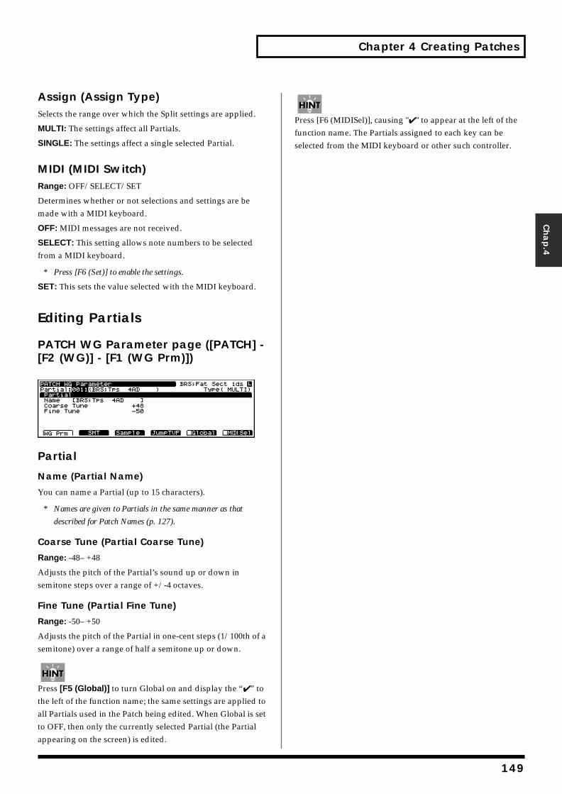
Chapter 4 Creating Patches
Chap.4
Assign (Assign Type)Selects the range over which the Split settings are applied.
MULTI: The settings affect all Partials.
SINGLE: The settings affect a single selected Partial.
MIDI (MIDI Switch)Range: OFF/SELECT/SET
Determines whether or not selections and settings are be made with a MIDI keyboard.
OFF: MIDI messages are not received.
SELECT: This setting allows note numbers to be selected from a MIDI keyboard.
* Press [F6 (Set)] to enable the settings.
SET: This sets the value selected with the MIDI keyboard.
Editing Partials
PATCH WG Parameter page ([PATCH] - [F2 (WG)] - [F1 (WG Prm)])fig.04-060.e_70
Partial
Name (Partial Name)
You can name a Partial (up to 15 characters).
* Names are given to Partials in the same manner as that
described for Patch Names (p. 127).
Coarse Tune (Partial Coarse Tune)
Range: -48– +48
Adjusts the pitch of the Partial’s sound up or down in semitone steps over a range of +/-4 octaves.
Fine Tune (Partial Fine Tune)
Range: -50– +50
Adjusts the pitch of the Partial in one-cent steps (1/100th of a semitone) over a range of half a semitone up or down.
Press [F5 (Global)] to turn Global on and display the “✔ ” to the left of the function name; the same settings are applied to all Partials used in the Patch being edited. When Global is set to OFF, then only the currently selected Partial (the Partial appearing on the screen) is edited.
Press [F6 (MIDISel)], causing "✔ " to appear at the left of the function name. The Partials assigned to each key can be selected from the MIDI keyboard or other such controller.
149
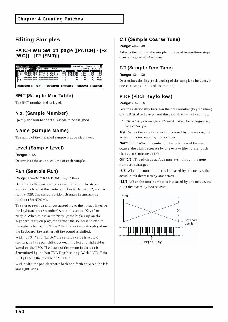
Chapter 4 Creating Patches
Editing Samples
PATCH WG SMT#1 page ([PATCH] - [F2 (WG)] - [F2 (SMT)])fig.04-061.e_70
SMT (Sample Mix Table)The SMT number is displayed.
No. (Sample Number)Specify the number of the Sample to be assigned.
Name (Sample Name)The name of the assigned sample will be displayed.
Level (Sample Level)Range: 0–127
Determines the sound volume of each sample.
Pan (Sample Pan)Range: L32–32R/RANDOM/Key+/Key-
Determines the pan setting for each sample. The stereo position is fixed at the center at 0, the far left at L32, and far right at 32R. The stereo position changes irregularly at random (RANDOM).
The stereo position changes according to the notes played on the keyboard (note number) when it is set to “Key+” or “Key-.” When this is set to “Key+,” the higher up on the keyboard that you play, the further the sound is shifted to the right; when set to “Key-,” the higher the notes played on the keyboard, the further left the sound is shifted.
With “LFO+” and “LFO-,” the settings value is set to 0 (center), and the pan shifts between the left and right sides based on the LFO. The depth of the swing in the pan is determined by the Pan TVA Depth setting. With “LFO-,” the LFO phase is the reverse of “LFO+.”
With “Alt,” the pan alternates back and forth between the left and right sides.
C.T (Sample Coarse Tune)Range: -48– +48
Adjusts the pitch of the sample to be used in semitone steps over a range of +/-4 octaves.
F.T (Sample Fine Tune)Range: -50– +50
Determines the fine pitch setting of the sample to be used, in one-cent steps (1/100 of a semitone).
P.KF (Pitch Keyfollow)Range: -16– +16
Sets the relationship between the note number (key position) of the Partial to be used and the pitch that actually sounds.
* The pitch of the Sample is changed relative to the original key
of each Sample.
16/8: When the note number is increased by one octave, the actual pitch increases by two octaves.
Norm (8/8): When the note number is increased by one octave, the pitch increases by one octave (the normal pitch change in semitone units).
Off (0/8): The pitch doesn’t change even though the note number is changed.
-8/8: When the note number is increased by one octave, the actual pitch decreases by one octave.
-16/8: When the note number is increased by one octave, the pitch decreases by two octaves.fig.04-062.e
Pitch
Keyboardposition
Original Key
88
Off
88
150
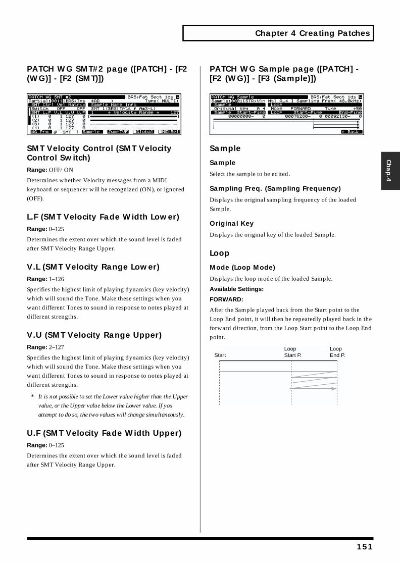
Chapter 4 Creating Patches
Chap.4
PATCH WG SMT#2 page ([PATCH] - [F2 (WG)] - [F2 (SMT)])fig.04-063.e_70
SMT Velocity Control (SMT Velocity Control Switch)Range: OFF/ON
Determines whether Velocity messages from a MIDI keyboard or sequencer will be recognized (ON), or ignored (OFF).
L.F (SMT Velocity Fade Width Lower)Range: 0–125
Determines the extent over which the sound level is faded after SMT Velocity Range Upper.
V.L (SMT Velocity Range Lower)Range: 1–126
Specifies the highest limit of playing dynamics (key velocity) which will sound the Tone. Make these settings when you want different Tones to sound in response to notes played at different strengths.
V.U (SMT Velocity Range Upper)Range: 2–127
Specifies the highest limit of playing dynamics (key velocity) which will sound the Tone. Make these settings when you want different Tones to sound in response to notes played at different strengths.
* It is not possible to set the Lower value higher than the Upper
value, or the Upper value below the Lower value. If you
attempt to do so, the two values will change simultaneously.
U.F (SMT Velocity Fade Width Upper)Range: 0–125
Determines the extent over which the sound level is faded after SMT Velocity Range Upper.
PATCH WG Sample page ([PATCH] - [F2 (WG)] - [F3 (Sample)])fig.04-065.e_70
Sample
Sample
Select the sample to be edited.
Sampling Freq. (Sampling Frequency)
Displays the original sampling frequency of the loaded Sample.
Original Key
Displays the original key of the loaded Sample.
Loop
Mode (Loop Mode)
Displays the loop mode of the loaded Sample.
Available Settings:
FORWARD:
After the Sample played back from the Start point to the Loop End point, it will then be repeatedly played back in the forward direction, from the Loop Start point to the Loop End point.
StartLoopStart P.
LoopEnd P.
151
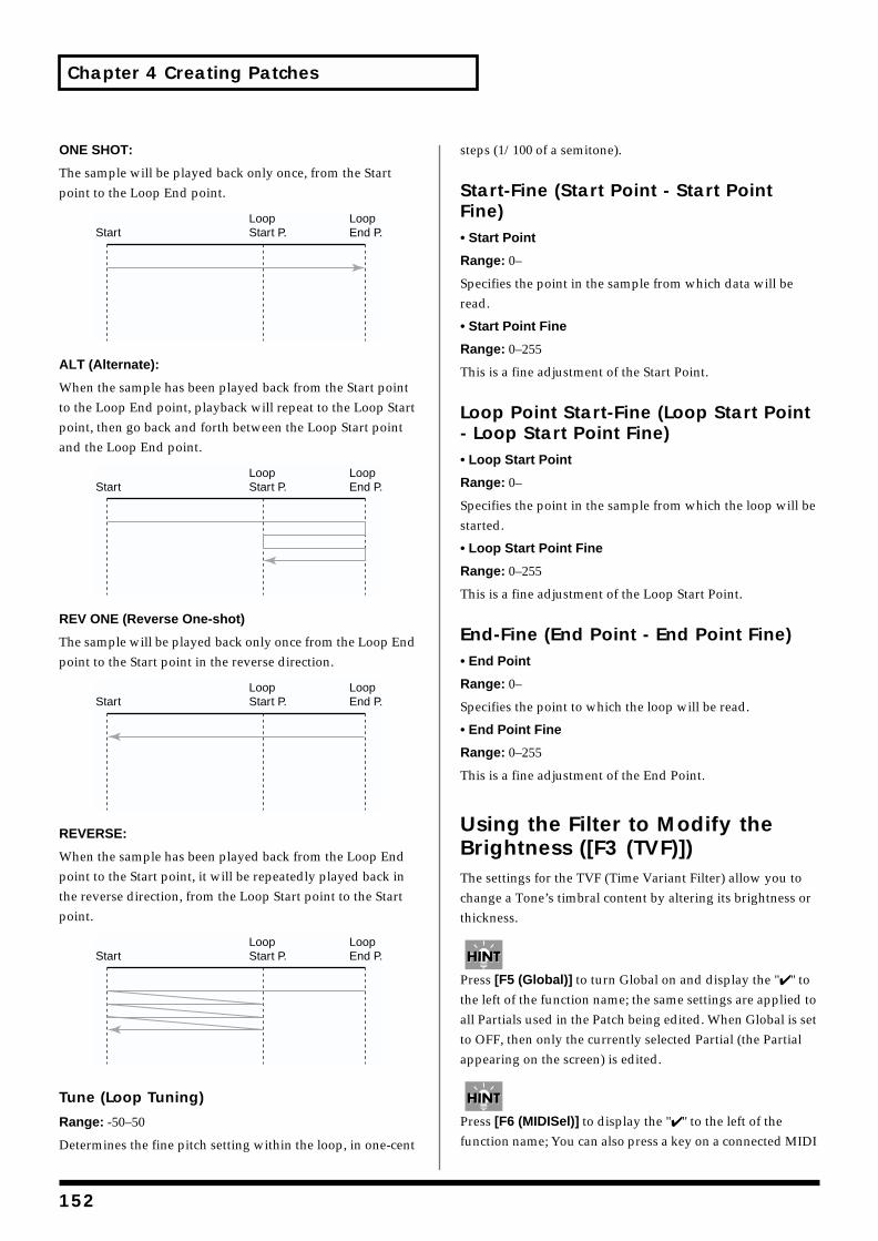
Chapter 4 Creating Patches
ONE SHOT:
The sample will be played back only once, from the Start point to the Loop End point.
ALT (Alternate):
When the sample has been played back from the Start point to the Loop End point, playback will repeat to the Loop Start point, then go back and forth between the Loop Start point and the Loop End point.
REV ONE (Reverse One-shot)
The sample will be played back only once from the Loop End point to the Start point in the reverse direction.
REVERSE:
When the sample has been played back from the Loop End point to the Start point, it will be repeatedly played back in the reverse direction, from the Loop Start point to the Start point.
Tune (Loop Tuning)
Range: -50–50
Determines the fine pitch setting within the loop, in one-cent
steps (1/100 of a semitone).
Start-Fine (Start Point - Start Point Fine)• Start Point
Range: 0–
Specifies the point in the sample from which data will be read.
• Start Point Fine
Range: 0–255
This is a fine adjustment of the Start Point.
Loop Point Start-Fine (Loop Start Point - Loop Start Point Fine)• Loop Start Point
Range: 0–
Specifies the point in the sample from which the loop will be started.
• Loop Start Point Fine
Range: 0–255
This is a fine adjustment of the Loop Start Point.
End-Fine (End Point - End Point Fine)• End Point
Range: 0–
Specifies the point to which the loop will be read.
• End Point Fine
Range: 0–255
This is a fine adjustment of the End Point.
Using the Filter to Modify the Brightness ([F3 (TVF)])The settings for the TVF (Time Variant Filter) allow you to change a Tone’s timbral content by altering its brightness or thickness.
Press [F5 (Global)] to turn Global on and display the "✔ " to the left of the function name; the same settings are applied to all Partials used in the Patch being edited. When Global is set to OFF, then only the currently selected Partial (the Partial appearing on the screen) is edited.
Press [F6 (MIDISel)] to display the "✔ " to the left of the function name; You can also press a key on a connected MIDI
StartLoopStart P.
LoopEnd P.
StartLoopStart P.
LoopEnd P.
StartLoopStart P.
LoopEnd P.
StartLoopStart P.
LoopEnd P.
152
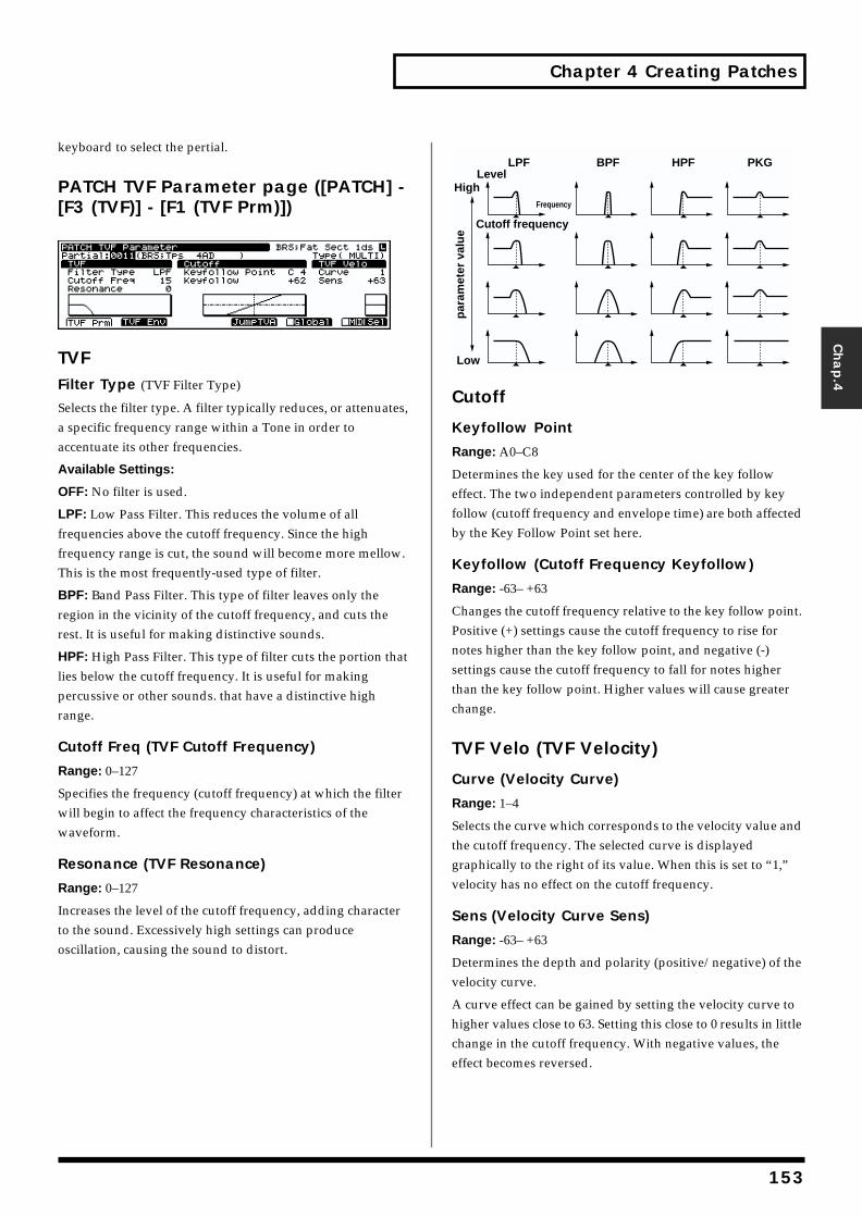
Chapter 4 Creating Patches
Chap.4
keyboard to select the pertial.
PATCH TVF Parameter page ([PATCH] - [F3 (TVF)] - [F1 (TVF Prm)])fig.04-066.e_70
TVFFilter Type (TVF Filter Type)
Selects the filter type. A filter typically reduces, or attenuates, a specific frequency range within a Tone in order to accentuate its other frequencies.
Available Settings:
OFF: No filter is used.
LPF: Low Pass Filter. This reduces the volume of all frequencies above the cutoff frequency. Since the high frequency range is cut, the sound will become more mellow. This is the most frequently-used type of filter.
BPF: Band Pass Filter. This type of filter leaves only the region in the vicinity of the cutoff frequency, and cuts the rest. It is useful for making distinctive sounds.
HPF: High Pass Filter. This type of filter cuts the portion that lies below the cutoff frequency. It is useful for making percussive or other sounds. that have a distinctive high range.
Cutoff Freq (TVF Cutoff Frequency)
Range: 0–127
Specifies the frequency (cutoff frequency) at which the filter will begin to affect the frequency characteristics of the waveform.
Resonance (TVF Resonance)
Range: 0–127
Increases the level of the cutoff frequency, adding character to the sound. Excessively high settings can produce oscillation, causing the sound to distort.
fig.04-067.e_70
Cutoff
Keyfollow Point
Range: A0–C8
Determines the key used for the center of the key follow effect. The two independent parameters controlled by key follow (cutoff frequency and envelope time) are both affected by the Key Follow Point set here.
Keyfollow (Cutoff Frequency Keyfollow)
Range: -63– +63
Changes the cutoff frequency relative to the key follow point. Positive (+) settings cause the cutoff frequency to rise for notes higher than the key follow point, and negative (-) settings cause the cutoff frequency to fall for notes higher than the key follow point. Higher values will cause greater change.
TVF Velo (TVF Velocity)
Curve (Velocity Curve)
Range: 1–4
Selects the curve which corresponds to the velocity value and the cutoff frequency. The selected curve is displayed graphically to the right of its value. When this is set to “1,” velocity has no effect on the cutoff frequency.
Sens (Velocity Curve Sens)
Range: -63– +63
Determines the depth and polarity (positive/negative) of the velocity curve.
A curve effect can be gained by setting the velocity curve to higher values close to 63. Setting this close to 0 results in little change in the cutoff frequency. With negative values, the effect becomes reversed.
LPF BPF HPF PKG
par
amet
er v
alu
e
Level
Cutoff frequency
Frequency
High
Low
153

Chapter 4 Creating Patches
PATCH TVF Envelope page ([PATCH] - [F3 (TVF)] - [F2 (TVF Env)])These parameters determine the amount of filter enveloping – changes to your original cutoff frequency setting that occur over time – the effect of velocity on the TVF envelope, and the basic characteristics of the TVF envelope itself.fig.04-068.e_70
TVF Envelopefig.04-069.e
Depth (TVF Envelope Depth)
Range: -63– +63
Determines the depth of the envelope when changing the TVF cutoff frequency by the envelope. Higher settings will cause the envelope to produce greater effect. With a setting of zero, there will be no effect. With negative values, the effect is reversed.
Time Keyfollow (Envelope Time Keyfollow)
Range: -63– +63
Changes the envelope time (from Time 1 to 4) relative to the key follow point. Higher settings produce greater change. Positive (+) settings will reduce the time when higher keys are pressed. Negative (-) settings will extend time.
Time (TVF Envelope Time 1–4)
Range: 0–127
These settings determine the times over which the cutoff frequency setting will change from one TVF envelope level (L1–L4) to the next.
Level (TVF Envelope Level 0–3)
Range: 0–127
Each TVF envelope level value determines an amount of change to be applied to the original cutoff frequency setting.The Level during Note On is linked to L4.
Velo Sens
Amount (TVF Envelope Velocity Sensitivity)
Range: -63– +63
Use this parameter when you want keyboard playing dynamics (velocity) to affect the depth of the TVF envelope. For higher settings, there will be a greater difference between softly and strongly played notes. Negative (-) values invert the change.
Time1 (TVF Envelope Time 1 Velocity Sensitivity)
Range: -63– +63
Use this parameter when you want keyboard playing dynamics (velocity) to affect T1 (Time 1) of the TVF envelope. For higher settings, there will be a greater difference between softly and strongly played notes. With positive (+) settings, greater keyboard velocity will reduce the T1 setting. With negative (-) settings, greater keyboard velocity will increase the T1 setting.
Time4 (TVF Envelope Time 4 Velocity Sensitivity)
Range: -63– +63
Use this parameter when you want keyboard playing dynamics (velocity) to affect T4 (Time 4) of the TVF envelope. With higher settings, the T4 value will change more significantly depending on whether you release the key slowly or quickly. With positive (+) settings, greater keyboard velocity will reduce the T4 setting. With negative (-) settings, greater keyboard velocity will increase the T4 setting.
Pitch Depth (Envelope Pitch Depth)Range: -63– +63
The TVF envelope can be used to change not only the cutoff frequency, but also the pitch. Set the effect depth using this parameter when modifying the pitch with the TVF envelope. Higher settings will cause the envelope to produce greater effect. With a setting of zero, there will be no effect. With negative values, the effect is reversed.
T1 T2 T3 T4
L3
L1
L2
L4
L0
CutoffFrequency
Timekey ispressed
key isreleased
154
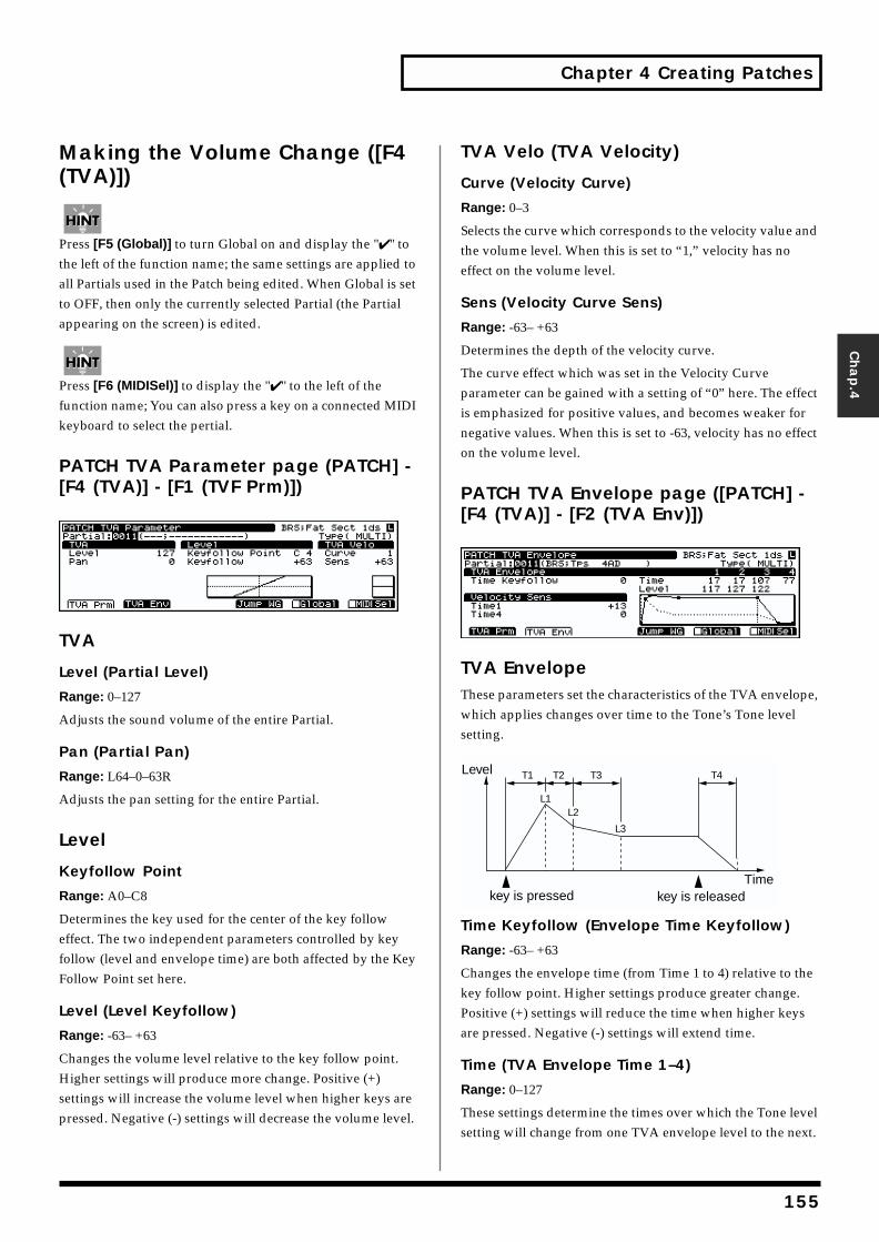
Chapter 4 Creating Patches
Chap.4
Making the Volume Change ([F4 (TVA)])
Press [F5 (Global)] to turn Global on and display the "✔ " to the left of the function name; the same settings are applied to all Partials used in the Patch being edited. When Global is set to OFF, then only the currently selected Partial (the Partial appearing on the screen) is edited.
Press [F6 (MIDISel)] to display the "✔ " to the left of the function name; You can also press a key on a connected MIDI keyboard to select the pertial.
PATCH TVA Parameter page (PATCH] - [F4 (TVA)] - [F1 (TVF Prm)])fig.04-070.e_70
TVA
Level (Partial Level)
Range: 0–127
Adjusts the sound volume of the entire Partial.
Pan (Partial Pan)
Range: L64–0–63R
Adjusts the pan setting for the entire Partial.
Level
Keyfollow Point
Range: A0–C8
Determines the key used for the center of the key follow effect. The two independent parameters controlled by key follow (level and envelope time) are both affected by the Key Follow Point set here.
Level (Level Keyfollow)
Range: -63– +63
Changes the volume level relative to the key follow point. Higher settings will produce more change. Positive (+) settings will increase the volume level when higher keys are pressed. Negative (-) settings will decrease the volume level.
TVA Velo (TVA Velocity)
Curve (Velocity Curve)
Range: 0–3
Selects the curve which corresponds to the velocity value and the volume level. When this is set to “1,” velocity has no effect on the volume level.
Sens (Velocity Curve Sens)
Range: -63– +63
Determines the depth of the velocity curve.
The curve effect which was set in the Velocity Curve parameter can be gained with a setting of “0” here. The effect is emphasized for positive values, and becomes weaker for negative values. When this is set to -63, velocity has no effect on the volume level.
PATCH TVA Envelope page ([PATCH] - [F4 (TVA)] - [F2 (TVA Env)])fig.04-071.e_70
TVA EnvelopeThese parameters set the characteristics of the TVA envelope, which applies changes over time to the Tone’s Tone level setting.fig.04-072.e
Time Keyfollow (Envelope Time Keyfollow)
Range: -63– +63
Changes the envelope time (from Time 1 to 4) relative to the key follow point. Higher settings produce greater change. Positive (+) settings will reduce the time when higher keys are pressed. Negative (-) settings will extend time.
Time (TVA Envelope Time 1–4)
Range: 0–127
These settings determine the times over which the Tone level setting will change from one TVA envelope level to the next.
T1 T2 T3 T4
L3
L1L2
Level
key is pressed key is releasedTime
155
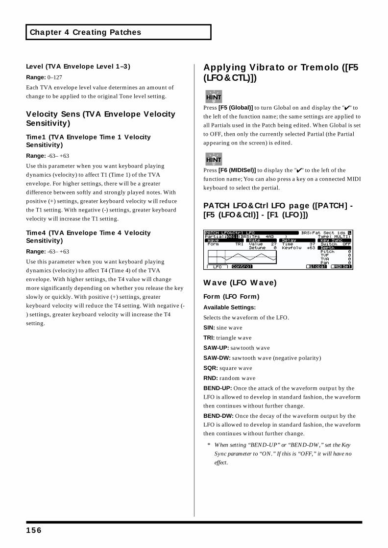
Chapter 4 Creating Patches
Level (TVA Envelope Level 1–3)
Range: 0–127
Each TVA envelope level value determines an amount of change to be applied to the original Tone level setting.
Velocity Sens (TVA Envelope Velocity Sensitivity)
Time1 (TVA Envelope Time 1 Velocity Sensitivity)
Range: -63– +63
Use this parameter when you want keyboard playing dynamics (velocity) to affect T1 (Time 1) of the TVA envelope. For higher settings, there will be a greater difference between softly and strongly played notes. With positive (+) settings, greater keyboard velocity will reduce the T1 setting. With negative (-) settings, greater keyboard velocity will increase the T1 setting.
Time4 (TVA Envelope Time 4 Velocity Sensitivity)
Range: -63– +63
Use this parameter when you want keyboard playing dynamics (velocity) to affect T4 (Time 4) of the TVA envelope. With higher settings, the T4 value will change more significantly depending on whether you release the key slowly or quickly. With positive (+) settings, greater keyboard velocity will reduce the T4 setting. With negative (-) settings, greater keyboard velocity will increase the T4 setting.
Applying Vibrato or Tremolo ([F5 (LFO&CTL)])
Press [F5 (Global)] to turn Global on and display the "✔ " to the left of the function name; the same settings are applied to all Partials used in the Patch being edited. When Global is set to OFF, then only the currently selected Partial (the Partial appearing on the screen) is edited.
Press [F6 (MIDISel)] to display the "✔ " to the left of the function name; You can also press a key on a connected MIDI keyboard to select the pertial.
PATCH LFO&Ctrl LFO page ([PATCH] - [F5 (LFO&Ctl)] - [F1 (LFO)])fig.04-073.e_70
Wave (LFO Wave)
Form (LFO Form)
Available Settings:
Selects the waveform of the LFO.
SIN: sine wave
TRI: triangle wave
SAW-UP: sawtooth wave
SAW-DW: sawtooth wave (negative polarity)
SQR: square wave
RND: random wave
BEND-UP: Once the attack of the waveform output by the LFO is allowed to develop in standard fashion, the waveform then continues without further change.
BEND-DW: Once the decay of the waveform output by the LFO is allowed to develop in standard fashion, the waveform then continues without further change.
* When setting “BEND-UP” or “BEND-DW,” set the Key
Sync parameter to “ON.” If this is “OFF,” it will have no
effect.
156
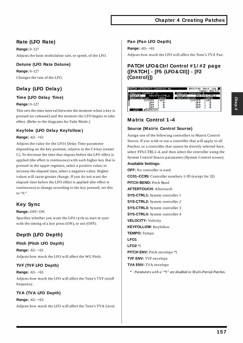
Chapter 4 Creating Patches
Chap.4
Rate (LFO Rate)Range: 0–127
Adjusts the basic modulation rate, or speed, of the LFO.
Detune (LFO Rate Detune)
Range: 0–127
Changes the rate of the LFO.
Delay (LFO Delay)
Time (LFO Delay Time)
Range: 0–127
This sets the time interval between the moment when a key is pressed (or released) and the moment the LFO begins to take effect. (Refer to the diagrams for Fade Mode.)
Keyfolw (LFO Delay Keyfollow)
Range: -63– +63
Adjusts the value for the LFO1 Delay Time parameter depending on the key position, relative to the C4 key (center C). To decrease the time that elapses before the LFO effect is applied (the effect is continuous) with each higher key that is pressed in the upper registers, select a positive value; to increase the elapsed time, select a negative value. Higher values will cause greater change. If you do not want the elapsed time before the LFO effect is applied (the effect is continuous) to change according to the key pressed, set this to “0.”
Key SyncRange: OFF/ON
Specifies whether you want the LFO cycle to start in sync with the timing of a key press (ON), or not (OFF).
Depth (LFO Depth)
Pitch (Pitch LFO Depth)
Range: -63– +63
Adjusts how much the LFO will affect the WG Pitch.
TVF (TVF LFO Depth)
Range: -63– +63
Adjusts how much the LFO will affect the Tone’s TVF cutoff frequency.
TVA (TVA LFO Depth)
Range: -63– +63
Adjusts how much the LFO will affect the Tone’s TVA Level.
Pan (Pan LFO Depth)
Range: -63– +63
Adjusts how much the LFO will affect the Tone’s TVA Pan.
PATCH LFO&Ctrl Control #1/#2 page ([PATCH] - [F5 (LFO&Ctl)] - [F2 (Control)])fig.04-074.e_70
Matrix Control 1–4
Source (Matrix Control Source)
Assign one of the following controllers to Matrix Control Source. If you wish to use a controller that will apply to all Patches, or a controller that cannot be directly selected here, select SYS-CTRL1–4, and then select the controller using the System Control Source parameters (System Control screen).
Available Settings:
OFF: No controller is used.
CC01–CC95: Controller numbers 1–95 (except for 32)
PITCH BEND: Pitch Bend
AFTERTOUCH: Aftertouch
SYS-CTRL1: System controller 1
SYS-CTRL2: System controller 2
SYS-CTRL3: System controller 3
SYS-CTRL4: System controller 4
VELOCITY: Velocity
KEYFOLLOW: Keyfollow
TEMPO: Tempo
LFO1
LFO2 *1
PITCH ENV: Pitch envelope *1
TVF ENV: TVF envelope
TVA ENV: TVA envelope
* Parameters with a "*1" are disabled in Multi-Partial Patches.
157
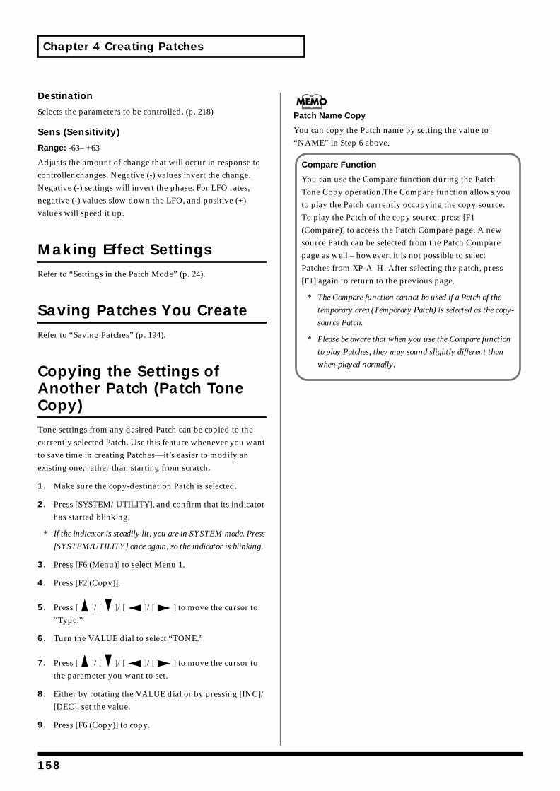
Chapter 4 Creating Patches
Destination
Selects the parameters to be controlled. (p. 218)
Sens (Sensitivity)
Range: -63– +63
Adjusts the amount of change that will occur in response to controller changes. Negative (-) values invert the change. Negative (-) settings will invert the phase. For LFO rates, negative (-) values slow down the LFO, and positive (+) values will speed it up.
Making Effect SettingsRefer to “Settings in the Patch Mode” (p. 24).
Saving Patches You CreateRefer to “Saving Patches” (p. 194).
Copying the Settings of Another Patch (Patch Tone Copy)Tone settings from any desired Patch can be copied to the currently selected Patch. Use this feature whenever you want to save time in creating Patches—it’s easier to modify an existing one, rather than starting from scratch.
1. Make sure the copy-destination Patch is selected.
2. Press [SYSTEM/UTILITY], and confirm that its indicator has started blinking.
* If the indicator is steadily lit, you are in SYSTEM mode. Press
[SYSTEM/UTILITY] once again, so the indicator is blinking.
3. Press [F6 (Menu)] to select Menu 1.
4. Press [F2 (Copy)].
5. Press [ ]/[ ]/[ ]/[ ] to move the cursor to “Type.”
6. Turn the VALUE dial to select “TONE.”
7. Press [ ]/[ ]/[ ]/[ ] to move the cursor to the parameter you want to set.
8. Either by rotating the VALUE dial or by pressing [INC]/[DEC], set the value.
9. Press [F6 (Copy)] to copy.
Patch Name Copy
You can copy the Patch name by setting the value to “NAME” in Step 6 above.
Compare Function
You can use the Compare function during the Patch Tone Copy operation.The Compare function allows you to play the Patch currently occupying the copy source. To play the Patch of the copy source, press [F1 (Compare)] to access the Patch Compare page. A new source Patch can be selected from the Patch Compare page as well – however, it is not possible to select Patches from XP-A–H. After selecting the patch, press [F1] again to return to the previous page.
* The Compare function cannot be used if a Patch of the
temporary area (Temporary Patch) is selected as the copy-
source Patch.
* Please be aware that when you use the Compare function
to play Patches, they may sound slightly different than
when played normally.
158
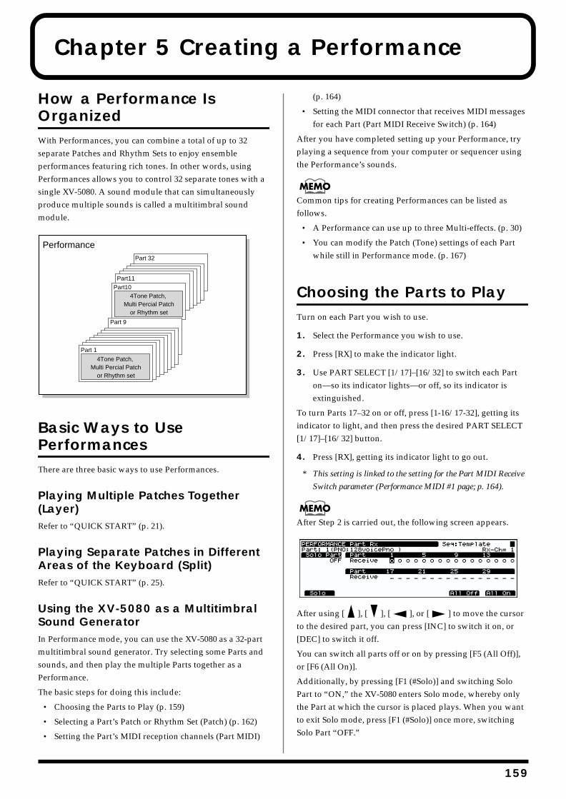
Chapter 5 Creating a Performance
How a Performance Is OrganizedWith Performances, you can combine a total of up to 32 separate Patches and Rhythm Sets to enjoy ensemble performances featuring rich tones. In other words, using Performances allows you to control 32 separate tones with a single XV-5080. A sound module that can simultaneously produce multiple sounds is called a multitimbral sound module.fig.05-001.e
Basic Ways to Use PerformancesThere are three basic ways to use Performances.
Playing Multiple Patches Together (Layer)Refer to “QUICK START” (p. 21).
Playing Separate Patches in Different Areas of the Keyboard (Split)Refer to “QUICK START” (p. 25).
Using the XV-5080 as a Multitimbral Sound GeneratorIn Performance mode, you can use the XV-5080 as a 32-part multitimbral sound generator. Try selecting some Parts and sounds, and then play the multiple Parts together as a Performance.
The basic steps for doing this include:
• Choosing the Parts to Play (p. 159)
• Selecting a Part’s Patch or Rhythm Set (Patch) (p. 162)
• Setting the Part’s MIDI reception channels (Part MIDI)
(p. 164)
• Setting the MIDI connector that receives MIDI messages for each Part (Part MIDI Receive Switch) (p. 164)
After you have completed setting up your Performance, try playing a sequence from your computer or sequencer using the Performance’s sounds.
Common tips for creating Performances can be listed as follows.
• A Performance can use up to three Multi-effects. (p. 30)
• You can modify the Patch (Tone) settings of each Part while still in Performance mode. (p. 167)
Choosing the Parts to PlayTurn on each Part you wish to use.
1. Select the Performance you wish to use.
2. Press [RX] to make the indicator light.
3. Use PART SELECT [1/17]–[16/32] to switch each Part on—so its indicator lights—or off, so its indicator is extinguished.
To turn Parts 17–32 on or off, press [1-16/17-32], getting its indicator to light, and then press the desired PART SELECT [1/17]–[16/32] button.
4. Press [RX], getting its indicator light to go out.
* This setting is linked to the setting for the Part MIDI Receive
Switch parameter (Performance MIDI #1 page; p. 164).
After Step 2 is carried out, the following screen appears.fig.
After using [ ], [ ], [ ], or [ ] to move the cursor to the desired part, you can press [INC] to switch it on, or [DEC] to switch it off.
You can switch all parts off or on by pressing [F5 (All Off)], or [F6 (All On)].
Additionally, by pressing [F1 (#Solo)] and switching Solo Part to “ON,” the XV-5080 enters Solo mode, whereby only the Part at which the cursor is placed plays. When you want to exit Solo mode, press [F1 (#Solo)] once more, switching Solo Part “OFF.”
Performance
Part 1
Part 9
Part 10
Part11
Part 32
4Tone Patch, Multi Percial Patch
or Rhythm set
4Tone Patch, Multi Percial Patch
or Rhythm set
159
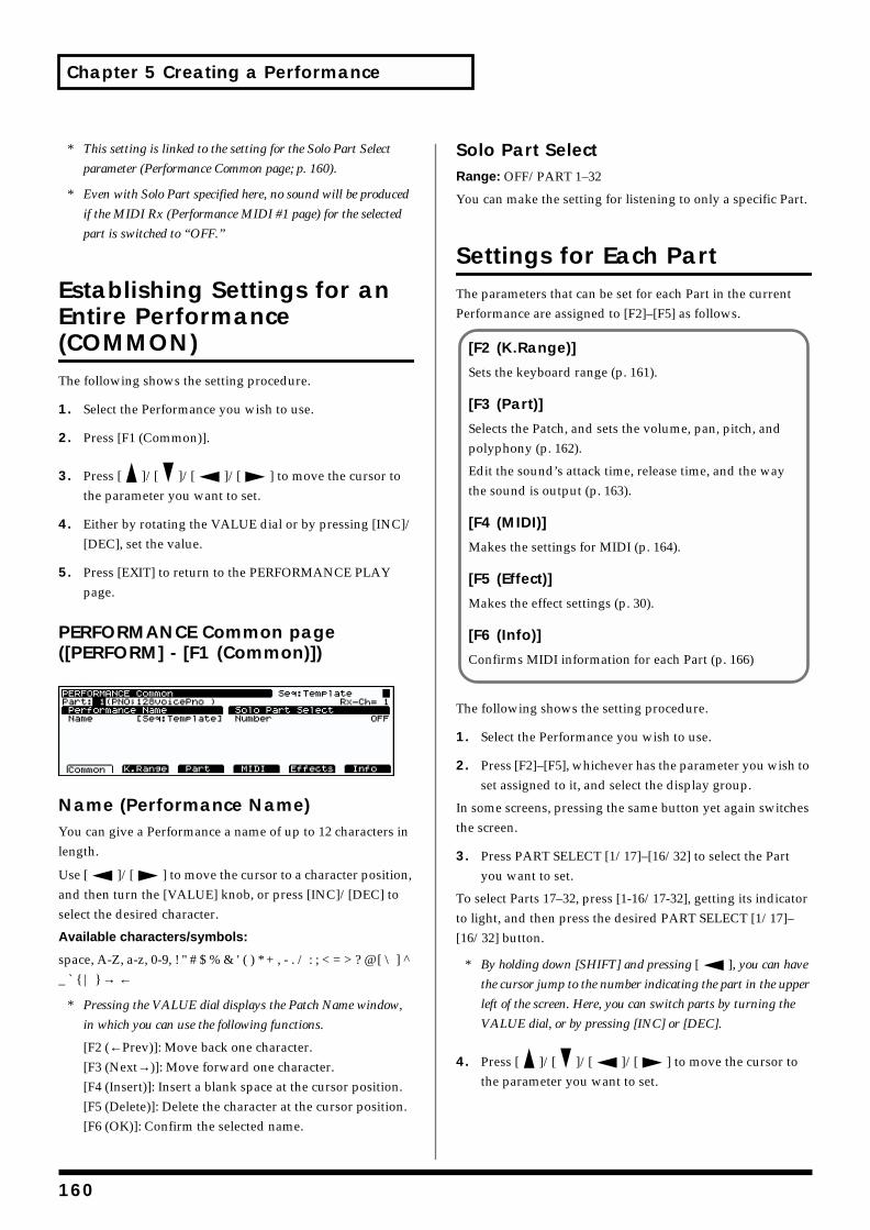
Chapter 5 Creating a Performance
* This setting is linked to the setting for the Solo Part Select
parameter (Performance Common page; p. 160).
* Even with Solo Part specified here, no sound will be produced
if the MIDI Rx (Performance MIDI #1 page) for the selected
part is switched to “OFF.”
Establishing Settings for an Entire Performance (COMMON)The following shows the setting procedure.
1. Select the Performance you wish to use.
2. Press [F1 (Common)].
3. Press [ ]/[ ]/[ ]/[ ] to move the cursor to the parameter you want to set.
4. Either by rotating the VALUE dial or by pressing [INC]/[DEC], set the value.
5. Press [EXIT] to return to the PERFORMANCE PLAY page.
PERFORMANCE Common page ([PERFORM] - [F1 (Common)])fig.05-002.e_70
Name (Performance Name)You can give a Performance a name of up to 12 characters in length.
Use [ ]/[ ] to move the cursor to a character position, and then turn the [VALUE] knob, or press [INC]/[DEC] to select the desired character.
Available characters/symbols:
space, A-Z, a-z, 0-9, ! " # $ % & ' ( ) * + , - . / : ; < = > ? @ [ \ ] ^ _ ` { | } → ←
* Pressing the VALUE dial displays the Patch Name window,
in which you can use the following functions.
[F2 (←Prev)]: Move back one character.[F3 (Next→)]: Move forward one character.[F4 (Insert)]: Insert a blank space at the cursor position.[F5 (Delete)]: Delete the character at the cursor position.[F6 (OK)]: Confirm the selected name.
Solo Part SelectRange: OFF/PART 1–32
You can make the setting for listening to only a specific Part.
Settings for Each PartThe parameters that can be set for each Part in the current Performance are assigned to [F2]–[F5] as follows.
The following shows the setting procedure.
1. Select the Performance you wish to use.
2. Press [F2]–[F5], whichever has the parameter you wish to set assigned to it, and select the display group.
In some screens, pressing the same button yet again switches the screen.
3. Press PART SELECT [1/17]–[16/32] to select the Part you want to set.
To select Parts 17–32, press [1-16/17-32], getting its indicator to light, and then press the desired PART SELECT [1/17]–[16/32] button.
* By holding down [SHIFT] and pressing [ ], you can have
the cursor jump to the number indicating the part in the upper
left of the screen. Here, you can switch parts by turning the
VALUE dial, or by pressing [INC] or [DEC].
4. Press [ ]/[ ]/[ ]/[ ] to move the cursor to the parameter you want to set.
[F2 (K.Range)]
Sets the keyboard range (p. 161).
[F3 (Part)]
Selects the Patch, and sets the volume, pan, pitch, and polyphony (p. 162).
Edit the sound’s attack time, release time, and the way the sound is output (p. 163).
[F4 (MIDI)]
Makes the settings for MIDI (p. 164).
[F5 (Effect)]
Makes the effect settings (p. 30).
[F6 (Info)]
Confirms MIDI information for each Part (p. 166)
160
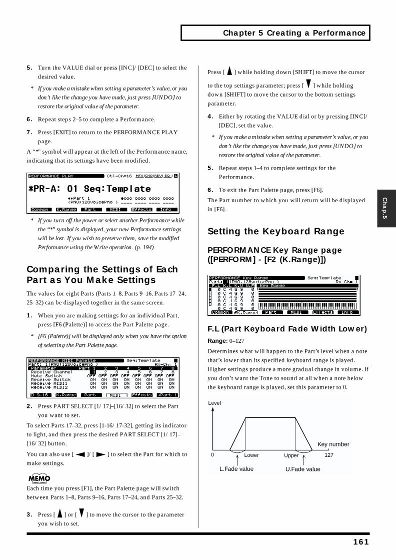
Chapter 5 Creating a Performance
Chap.5
5. Turn the VALUE dial or press [INC]/[DEC] to select the desired value.
* If you make a mistake when setting a parameter’s value, or you
don’t like the change you have made, just press [UNDO] to
restore the original value of the parameter.
6. Repeat steps 2–5 to complete a Performance.
7. Press [EXIT] to return to the PERFORMANCE PLAY page.
A “*” symbol will appear at the left of the Performance name, indicating that its settings have been modified.fig.05-003.e_70
* If you turn off the power or select another Performance while
the “*” symbol is displayed, your new Performance settings
will be lost. If you wish to preserve them, save the modified
Performance using the Write operation. (p. 194)
Comparing the Settings of Each Part as You Make SettingsThe values for eight Parts (Parts 1–8, Parts 9–16, Parts 17–24, 25–32) can be displayed together in the same screen.
1. When you are making settings for an individual Part, press [F6 (Palette)] to access the Part Palette page.
* [F6 (Palette)] will be displayed only when you have the option
of selecting the Part Palette page.fig.05-004.e_70
2. Press PART SELECT [1/17]–[16/32] to select the Part you want to set.
To select Parts 17–32, press [1-16/17-32], getting its indicator to light, and then press the desired PART SELECT [1/17]–[16/32] button.
You can also use [ ]/[ ] to select the Part for which to make settings.
Each time you press [F1], the Part Palette page will switch between Parts 1–8, Parts 9–16, Parts 17–24, and Parts 25–32.
3. Press [ ] or [ ] to move the cursor to the parameter you wish to set.
Press [ ] while holding down [SHIFT] to move the cursor
to the top settings parameter; press [ ] while holding down [SHIFT] to move the cursor to the bottom settings parameter.
4. Either by rotating the VALUE dial or by pressing [INC]/[DEC], set the value.
* If you make a mistake when setting a parameter’s value, or you
don’t like the change you have made, just press [UNDO] to
restore the original value of the parameter.
5. Repeat steps 1–4 to complete settings for the Performance.
6. To exit the Part Palette page, press [F6].
The Part number to which you will return will be displayed in [F6].
Setting the Keyboard Range
PERFORMANCE Key Range page ([PERFORM] - [F2 (K.Range)])fig.05-005.e_70
F.L (Part Keyboard Fade Width Lower)Range: 0–127
Determines what will happen to the Part’s level when a note that’s lower than its specified keyboard range is played. Higher settings produce a more gradual change in volume. If you don’t want the Tone to sound at all when a note below the keyboard range is played, set this parameter to 0.fig.05-006.e
L.Fade value U.Fade value
0 127
Level
UpperLower
Key number
161

Chapter 5 Creating a Performance
K.L (Part Keyboard Range Lower)Range: C -1–G9
Specifies the lowest note that will cause the Part to play its sound.
K.U (Part Keyboard Range Upper)Range: C -1–G9
Specifies the highest note that will cause the Part to play its sound.
The Lower value cannot be set to a value greater than Upper value, or vice versa. If you attempt to do this, the two values will change simultaneously.
U.F (Part Keyboard Fade Width Upper)Range: 0–127
This determines what will happen to the Part’s level when a note that’s higher than its specified keyboard range is played. Higher settings produce a more gradual change in volume. If you don’t want the Tone to sound at all when a note above the keyboard range is played, set this parameter to 0.
Selecting the Patch, and Setting the Volume, Pan, Pitch, and Polyphony
PERFORMANCE Part #1 page ([PERFORM] - [F3 (Part)])fig.05-007.e_70
Patch (Part Patch)
Type (Part Type)
Range: PAT/RHY
Selects the Patch (PAT) or Rhythm Set (RHY) the Part will play.
Group (Part Group)
Available Settings:
Selects the group to which the desired Patch or Rhythm Set belongs.
* You can also use the Patch Finder feature. (p. 19)
* You can also select from the FAVORITE LIST. (p. 207)
* It is not possible to select XP-A–H unless a wave expansion
board is inserted into the corresponding slot. (Quick Start; p.
3)
* It is not possible to select CARD unless a SmartMedia card is
inserted into the XV-5080 CARD slot.
Number
Selects the desired Patch or Rhythm Set by its number.
* You can also use the Patch Finder feature. (p. 19)
* You can also select from the FAVORITE LIST. (p. 207)
Level&Pan (Part Level&Pan)
Part Level
Available Settings:
Sets the volume of the Part. This setting’s main purpose is to adjust the volume balance between Parts.
Part Pan
Available Settings:
Specifies the stereo position of the Part’s sound. L64 is far left, 0 is center, and 63R is far right.
Tune (Part Tune)
Octave Shift (Part Octave Shift)
Range: -3– +3
Adjusts the pitch of the Part’s sound up or down in units of an octave (+/-3 octaves).
Coarse (Part Coarse Tune)
Range: -48– +48
Adjusts the pitch of the Part’s sound up or down in semitone steps over a range of +/-4 octaves.
Fine (Part Fine Tune)
Range: -50– +50
Adjusts the pitch of the Part’s sound up or down in one-cent steps (1/100th of a semitone) over a range of half a semitone up or down.
162
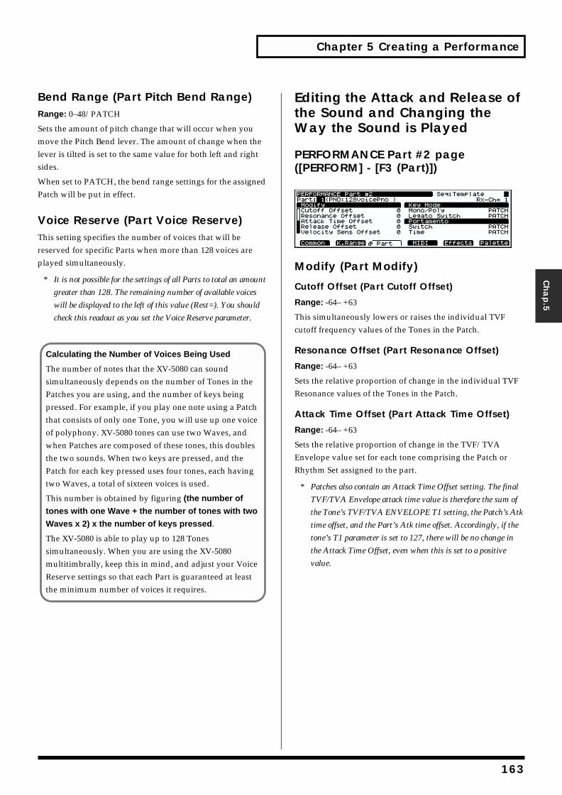
Chapter 5 Creating a Performance
Chap.5
Bend Range (Part Pitch Bend Range)Range: 0–48/PATCH
Sets the amount of pitch change that will occur when you move the Pitch Bend lever. The amount of change when the lever is tilted is set to the same value for both left and right sides.
When set to PATCH, the bend range settings for the assigned Patch will be put in effect.
Voice Reserve (Part Voice Reserve)This setting specifies the number of voices that will be reserved for specific Parts when more than 128 voices are played simultaneously.
* It is not possible for the settings of all Parts to total an amount
greater than 128. The remaining number of available voices
will be displayed to the left of this value (Rest=). You should
check this readout as you set the Voice Reserve parameter.
Editing the Attack and Release of the Sound and Changing the Way the Sound is Played
PERFORMANCE Part #2 page ([PERFORM] - [F3 (Part)])fig.05-008.e_70
Modify (Part Modify)
Cutoff Offset (Part Cutoff Offset)
Range: -64– +63
This simultaneously lowers or raises the individual TVF cutoff frequency values of the Tones in the Patch.
Resonance Offset (Part Resonance Offset)
Range: -64– +63
Sets the relative proportion of change in the individual TVF Resonance values of the Tones in the Patch.
Attack Time Offset (Part Attack Time Offset)
Range: -64– +63
Sets the relative proportion of change in the TVF/TVA Envelope value set for each tone comprising the Patch or Rhythm Set assigned to the part.
* Patches also contain an Attack Time Offset setting. The final
TVF/TVA Envelope attack time value is therefore the sum of
the Tone’s TVF/TVA ENVELOPE T1 setting, the Patch’s Atk
time offset, and the Part’s Atk time offset. Accordingly, if the
tone’s T1 parameter is set to 127, there will be no change in
the Attack Time Offset, even when this is set to a positive
value.
Calculating the Number of Voices Being Used
The number of notes that the XV-5080 can sound simultaneously depends on the number of Tones in the Patches you are using, and the number of keys being pressed. For example, if you play one note using a Patch that consists of only one Tone, you will use up one voice of polyphony. XV-5080 tones can use two Waves, and when Patches are composed of these tones, this doubles the two sounds. When two keys are pressed, and the Patch for each key pressed uses four tones, each having two Waves, a total of sixteen voices is used.
This number is obtained by figuring (the number of
tones with one Wave + the number of tones with two
Waves x 2) x the number of keys pressed.
The XV-5080 is able to play up to 128 Tones simultaneously. When you are using the XV-5080 multitimbrally, keep this in mind, and adjust your Voice Reserve settings so that each Part is guaranteed at least the minimum number of voices it requires.
163
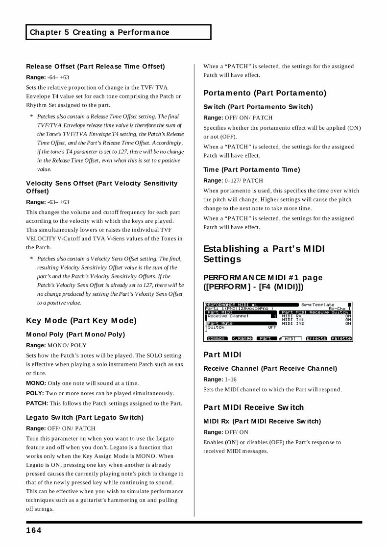
Chapter 5 Creating a Performance
Release Offset (Part Release Time Offset)
Range: -64– +63
Sets the relative proportion of change in the TVF/TVA Envelope T4 value set for each tone comprising the Patch or Rhythm Set assigned to the part.
* Patches also contain a Release Time Offset setting. The final
TVF/TVA Envelope release time value is therefore the sum of
the Tone’s TVF/TVA Envelope T4 setting, the Patch’s Release
Time Offset, and the Part’s Release Time Offset. Accordingly,
if the tone’s T4 parameter is set to 127, there will be no change
in the Release Time Offset, even when this is set to a positive
value.
Velocity Sens Offset (Part Velocity Sensitivity Offset)
Range: -63– +63
This changes the volume and cutoff frequency for each part according to the velocity with which the keys are played. This simultaneously lowers or raises the individual TVF VELOCITY V-Cutoff and TVA V-Sens values of the Tones in the Patch.
* Patches also contain a Velocity Sens Offset setting. The final,
resulting Velocity Sensitivity Offset value is the sum of the
part’s and the Patch’s Velocity Sensitivity Offsets. If the
Patch’s Velocity Sens Offset is already set to 127, there will be
no change produced by setting the Part’s Velocity Sens Offset
to a positive value.
Key Mode (Part Key Mode)
Mono/Poly (Part Mono/Poly)
Range: MONO/POLY
Sets how the Patch’s notes will be played. The SOLO setting is effective when playing a solo instrument Patch such as sax or flute.
MONO: Only one note will sound at a time.
POLY: Two or more notes can be played simultaneously.
PATCH: This follows the Patch settings assigned to the Part.
Legato Switch (Part Legato Switch)
Range: OFF/ON/PATCH
Turn this parameter on when you want to use the Legato feature and off when you don’t. Legato is a function that works only when the Key Assign Mode is MONO. When Legato is ON, pressing one key when another is already pressed causes the currently playing note’s pitch to change to that of the newly pressed key while continuing to sound. This can be effective when you wish to simulate performance techniques such as a guitarist’s hammering on and pulling off strings.
When a “PATCH” is selected, the settings for the assigned Patch will have effect.
Portamento (Part Portamento)
Switch (Part Portamento Switch)
Range: OFF/ON/PATCH
Specifies whether the portamento effect will be applied (ON) or not (OFF).
When a “PATCH” is selected, the settings for the assigned Patch will have effect.
Time (Part Portamento Time)
Range: 0–127/PATCH
When portamento is used, this specifies the time over which the pitch will change. Higher settings will cause the pitch change to the next note to take more time.
When a “PATCH” is selected, the settings for the assigned Patch will have effect.
Establishing a Part’s MIDI Settings
PERFORMANCE MIDI #1 page ([PERFORM] - [F4 (MIDI)])fig.05-009.e_70
Part MIDI
Receive Channel (Part Receive Channel)
Range: 1–16
Sets the MIDI channel to which the Part will respond.
Part MIDI Receive Switch
MIDI Rx (Part MIDI Receive Switch)
Range: OFF/ON
Enables (ON) or disables (OFF) the Part’s response to received MIDI messages.
164
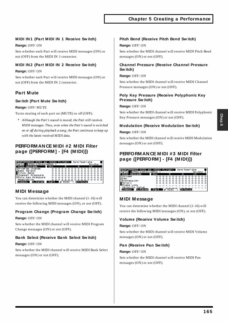
Chapter 5 Creating a Performance
Chap.5
MIDI IN1 (Part MIDI IN 1 Receive Switch)
Range: OFF/ON
Sets whether each Part will receive MIDI messages (ON) or not (OFF) from the MIDI IN 1 connector.
MIDI IN2 (Part MIDI IN 2 Receive Switch)
Range: OFF/ON
Sets whether each Part will receive MIDI messages (ON) or not (OFF) from the MIDI IN 2 connector.
Part Mute
Switch (Part Mute Switch)
Range: OFF/MUTE
Turns muting of each part on (MUTE) or off (OFF).
* Although the Part’s sound is muted, the Part still receives
MIDI messages. Thus, even when the Part’s sound is switched
on or off during playback a song, the Part continues to keep up
with the latest received MIDI data.
PERFORMANCE MIDI #2 MIDI Filter page ([PERFORM] - [F4 (MIDI)])fig.05-010.e_70
MIDI MessageYou can determine whether the MIDI channel (1–16) will receive the following MIDI messages (ON), or not (OFF).
Program Change (Program Change Switch)
Range: OFF/ON
Sets whether the MIDI channel will receive MIDI Program Change messages (ON) or not (OFF).
Bank Select (Receive Bank Select Switch)
Range: OFF/ON
Sets whether the MIDI channel will receive MIDI Bank Select messages (ON) or not (OFF).
Pitch Bend (Receive Pitch Bend Switch)
Range: OFF/ON
Sets whether the MIDI channel will receive MIDI Pitch Bend messages (ON) or not (OFF).
Channel Pressure (Receive Channel Pressure Switch)
Range: OFF/ON
Sets whether the MIDI channel will receive MIDI Channel Pressure messages (ON) or not (OFF).
Poly Key Pressure (Receive Polyphonic Key Pressure Switch)
Range: OFF/ON
Sets whether the MIDI channel will receive MIDI Polyphonic Key Pressure messages (ON) or not (OFF).
Modulation (Receive Modulation Switch)
Range: OFF/ON
Sets whether the MIDI channel will receive MIDI Modulation messages (ON) or not (OFF).
PERFORMANCE MIDI #3 MIDI Filter page ([PERFORM] - [F4 (MIDI)])fig.05-011.e_70
MIDI MessageYou can determine whether the MIDI channel (1–16) will receive the following MIDI messages (ON), or not (OFF).
Volume (Receive Volume Switch)
Range: OFF/ON
Sets whether the MIDI channel will receive MIDI Volume messages (ON) or not (OFF).
Pan (Receive Pan Switch)
Range: OFF/ON
Sets whether the MIDI channel will receive MIDI Pan messages (ON) or not (OFF).
165

Chapter 5 Creating a Performance
Expression (Receive Expression Switch)
Range: OFF/ON
Sets whether the MIDI channel will receive MIDI Expression messages (ON) or not (OFF).
Hold-1 (Receive Hold 1 Switch)
Range: OFF/ON
Sets whether the MIDI channel will receive MIDI Hold 1 messages (ON) or not (OFF).
Phase Lock
Range: OFF/ON
This setting activates (ON) or de-activates (OFF) synchronization of the timing of Parts that share a common MIDI channel.
* When Part sounds are layered on top of each other as a result
of sharing a MIDI channel, there may be a discrepancy in their
timing. The Phase Lock feature can synchronize the sounds so
that they start precisely at the same time. However, since this
delays the sounds slightly to line them up, turn this feature off
when it is not needed.
Velocity Curve
Range: OFF/1/2/3/4
For each Part, you can select from among four velocity curves to find the one that best matches the touch of the MIDI keyboard connected to the XV-5080. Set this to “OFF” if you are using the MIDI keyboard’s own velocity curve.
Confirming MIDI Information for Each MIDI Channel
PERFORMANCE Part Information page ([PERFORM] - [F6 (Info)])In this display you can check the receive status of various types of MIDI message for each MIDI channel. This is a convenient way to check that the sound generator is responding correctly to messages from the keyboard or external MIDI controllers.
The Part Info screen is split into three menus. Press [F6 (Menu)] to switch the menus.
Menu 1
• [F1] Mod (Modulation Information)
• [F2] Breath (Breath Information)
• [F3] Foot (Foot Information)
• [F4] Vol (Volume Information)
• [F5] Pan (Pan Information)
Menu 2
• [F1] Exp (Expression Information)
• [F2] Hold (Hold 1 Information)
• [F3] Bend (Pitch Bend Information)
• [F4] Aft (Aftertouch Information)
• [F5] Voices (Voice Information)
Menu 3
• [F1] Sys1 (System Control 1 Information)
• [F2] Sys2 (System Control 2 Information)
• [F3] Sys3 (System Control 2 Information)
• [F4] Sys4 (System Control 2 Information)
Making Effect SettingsRefer to “Settings in the Performance Mode” (p. 30).
Saving Performances You CreateRefer to “Saving Performances” (p. 194).
Copying the Settings of Another Part (Performance Part Copy)1. Make sure that the copy-destination Performance is
selected.
2. Press [SYSTEM/UTILITY], getting its indicator to start blinking.
* If the indicator is steadily lit, you are in SYSTEM mode. Press
[SYSTEM/UTILITY] once again, so the indicator is blinking.
3. Press [F6 (Menu)] to select Menu 1.
4. Press [F2 (Copy)].
166
Chapter 5 Creating a Performance
Chap.5
5. Press [ ]/[ ]/[ ]/[ ] to move the cursor to “Type.”
6. Turn the VALUE dial to select “PART.”
7. Press [ ]/[ ]/[ ]/[ ] to move the cursor to the parameter you want to set.
8. Either by rotating the VALUE dial or by pressing [INC]/[DEC], set the value.
9. Press [F6 (Copy)] to initiate the copy procedure.
Performance Name Copy
You can copy the Patch name by setting the value to “NAME” in Step 6 above.
Editing a Patch or Rhythm Set in the Performance ModeWhile creating a Performance, you can call up the Patches and Rhythm Sets assigned to each part and change their settings.
1. Make sure that the PERFORM PLAY page is displayed.
2. Select the Part to which the Patch/Rhythm Set you wish to modify is assigned.
3. While holding down [SHIFT], press [PERFORM].
4. Press [PATCH] if you wish to edit a Patch, or [RHYTHM] to edit a Rhythm Set, lighting the respective indicator.
The Play page for the Patch/Rhythm Set assigned to the Part will appear.
5. These are changed using the same procedure used in regular editing of Patches and Rhythm Sets. (Creating a Patch; p. 125, Creating a Rhythm Set; p. 168)
6. When you finish making settings, press [EXIT] to return to the PLAY page.
A “*” symbol will appear at the left of the bank to indicate that the settings have been modified.
* If you want to keep the changes made in the settings, save
them here. (p. 194)
7. Press [PERFORM] to return to the PERFORM PLAY page.
* If you do not save the Patch or Rhythm Set, then even if you
save a Performance, changes in the Patch or Rhythm Set
settings are not saved. If you want to keep settings for the
Patch or Rhythm Set, be sure to save the changed settings after
carrying out Step 6.
Palette FunctionWhen editing a Part, you can simultaneously view the settings of all eight of its Parts by pressing [PALETTE].
1. When editing a Part, press [PALETTE] to make its indicator light.
2. Press a PART SELECT [1/9]–[8/16] button, [ ]/
[ ] to choose the Tone you wish to modify.
167
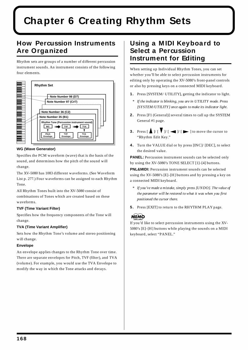
1
Chapter 6 Creating Rhythm Sets
How Percussion Instruments Are OrganizedRhythm sets are groups of a number of different percussion instrument sounds. An instrument consists of the following four elements.fig.06-001.e
WG (Wave Generator)
Specifies the PCM waveform (wave) that is the basis of the sound, and determines how the pitch of the sound will change.
The XV-5080 has 1083 different waveforms. (See Waveform List p. 277.) Four waveforms can be assigned to each Rhythm Tone.
All Rhythm Tones built into the XV-5080 consist of combinations of Tones which are created based on these waveforms.
TVF (Time Variant Filter)
Specifies how the frequency components of the Tone will change.
TVA (Time Variant Amplifier)
Sets how the Rhythm Tone’s volume and stereo positioning will change.
Envelope
An envelope applies changes to the Rhythm Tone over time. There are separate envelopes for Pitch, TVF (filter), and TVA (volume). For example, you would use the TVA Envelope to modify the way in which the Tone attacks and decays.
Using a MIDI Keyboard to Select a Percussion Instrument for EditingWhen setting up Individual Rhythm Tones, you can set whether you’ll be able to select percussion instruments for editing only by operating the XV-5080’s front-panel controls or also by pressing keys on a connected MIDI keyboard.
1. Press [SYSTEM/UTILITY], getting the indicator to light.
* If the indicator is blinking, you are in UTILITY mode. Press
[SYSTEM/UTILITY] once again to make its indicator light.
2. Press [F1 (General)] several times to call up the SYSTEM General #1 page.
3. Press [ ]/[ ]/[ ]/[ ] to move the cursor to “Rhythm Edit Key.”
4. Turn the VALUE dial or by press [INC]/[DEC], to select the desired value.
PANEL: Percussion instrument sounds can be selected only by using the XV-5080’s TONE SELECT [1]–[4] buttons.
PNL&MIDI: Percussion instrument sounds can be selected using the XV-5080’s [E]–[H] buttons and by pressing a key on a connected MIDI keyboard.
* If you’ve made a mistake, simply press [UNDO]. The value of
the parameter will be restored to what it was when you first
positioned the cursor there.
5. Press [EXIT] to return to the RHYTHM PLAY page.
If you’d like to select percussion instruments using the XV-5080’s [E]–[H] buttons while playing the sounds on a MIDI keyboard, select “PANEL.”
Note Number 98 (D7)
Note Number 97 (C#7)
Note Number 36 (C2)
Note Number 35 (B1)
Rhythm Tone (Percussion instrument sound)
Rhythm Set
WG
PitchEnvelope
TVF
TVF Envelope
TVA Envelope
TVA
68
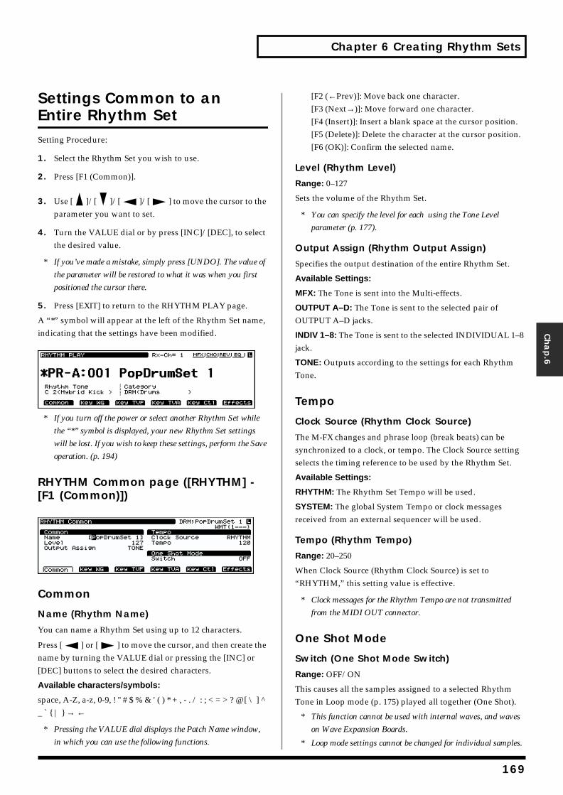
Chapter 6 Creating Rhythm Sets
Chap.6
Settings Common to an Entire Rhythm SetSetting Procedure:
1. Select the Rhythm Set you wish to use.
2. Press [F1 (Common)].
3. Use [ ]/[ ]/[ ]/[ ] to move the cursor to the parameter you want to set.
4. Turn the VALUE dial or by press [INC]/[DEC], to select the desired value.
* If you’ve made a mistake, simply press [UNDO]. The value of
the parameter will be restored to what it was when you first
positioned the cursor there.
5. Press [EXIT] to return to the RHYTHM PLAY page.
A “*” symbol will appear at the left of the Rhythm Set name, indicating that the settings have been modified.fig.06-002.e_70
* If you turn off the power or select another Rhythm Set while
the “*” symbol is displayed, your new Rhythm Set settings
will be lost. If you wish to keep these settings, perform the Save
operation. (p. 194)
RHYTHM Common page ([RHYTHM] - [F1 (Common)])fig.06-002a.e_70
Common
Name (Rhythm Name)
You can name a Rhythm Set using up to 12 characters.
Press [ ] or [ ] to move the cursor, and then create the name by turning the VALUE dial or pressing the [INC] or [DEC] buttons to select the desired characters.
Available characters/symbols:
space, A-Z, a-z, 0-9, ! " # $ % & ' ( ) * + , - . / : ; < = > ? @ [ \ ] ^ _ ` { | } → ←
* Pressing the VALUE dial displays the Patch Name window,
in which you can use the following functions.
[F2 (←Prev)]: Move back one character.[F3 (Next→)]: Move forward one character.[F4 (Insert)]: Insert a blank space at the cursor position.[F5 (Delete)]: Delete the character at the cursor position.[F6 (OK)]: Confirm the selected name.
Level (Rhythm Level)
Range: 0–127
Sets the volume of the Rhythm Set.
* You can specify the level for each using the Tone Level
parameter (p. 177).
Output Assign (Rhythm Output Assign)
Specifies the output destination of the entire Rhythm Set.
Available Settings:
MFX: The Tone is sent into the Multi-effects.
OUTPUT A–D: The Tone is sent to the selected pair of OUTPUT A–D jacks.
INDIV 1–8: The Tone is sent to the selected INDIVIDUAL 1–8 jack.
TONE: Outputs according to the settings for each Rhythm Tone.
Tempo
Clock Source (Rhythm Clock Source)
The M-FX changes and phrase loop (break beats) can be synchronized to a clock, or tempo. The Clock Source setting selects the timing reference to be used by the Rhythm Set.
Available Settings:
RHYTHM: The Rhythm Set Tempo will be used.
SYSTEM: The global System Tempo or clock messages received from an external sequencer will be used.
Tempo (Rhythm Tempo)
Range: 20–250
When Clock Source (Rhythm Clock Source) is set to “RHYTHM,” this setting value is effective.
* Clock messages for the Rhythm Tempo are not transmitted
from the MIDI OUT connector.
One Shot Mode
Switch (One Shot Mode Switch)
Range: OFF/ON
This causes all the samples assigned to a selected Rhythm Tone in Loop mode (p. 175) played all together (One Shot).
* This function cannot be used with internal waves, and waves
on Wave Expansion Boards.
* Loop mode settings cannot be changed for individual samples.
169
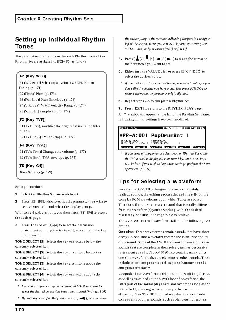
Chapter 6 Creating Rhythm Sets
Setting up Individual Rhythm TonesThe parameters that can be set for each Rhythm Tone of the Rhythm Set are assigned to [F2]–[F5] as follows.
Setting Procedure:
1. Select the Rhythm Set you wish to set.
2. Press [F2]–[F5], whichever has the parameter you wish to set assigned to it, and select the display group.
With some display groups, you then press [F1]–[F4] to access the desired page.
3. Press Tone Select [1]–[4] to select the percussion instrument sound you wish to edit, according to the key that plays it.
TONE SELECT [1]: Selects the key one octave below the currently selected key.
TONE SELECT [2]: Selects the key a semitone below the currently selected key.
TONE SELECT [3]: Selects the key a semitone above the currently selected key.
TONE SELECT [4]: Selects the key one octave above the currently selected key.
* You can also press a key on a connected MIDI keyboard to
select the desired percussion instrument sound (key). (p. 168)
* By holding down [SHIFT] and pressing [ ], you can have
the cursor jump to the number indicating the part in the upper
left of the screen. Here, you can switch parts by turning the
VALUE dial, or by pressing [INC] or [DEC].
4. Press [ ]/[ ]/[ ]/[ ] to move the cursor to the parameter you want to set.
5. Either turn the VALUE dial, or press [INC]/[DEC] to select the desired value.
* If you make a mistake when setting a parameter’s value, or you
don’t like the change you have made, just press [UNDO] to
restore the value the parameter originally had.
6. Repeat steps 2–5 to complete a Rhythm Set.
7. Press [EXIT] to return to the RHYTHM PLAY page.
A “*” symbol will appear at the left of the Rhythm Set name, indicating that its settings have been modified.fig.06-003.e_70
* If you turn off the power or select another Rhythm Set while
the “*” symbol is displayed, your new Rhythm Set settings
will be lost. If you wish to keep these settings, perform the Save
operation. (p. 194)
Tips for Selecting a WaveformBecause the XV-5080 is designed to create completely realistic sounds, the editing process depends heavily on the complex PCM waveforms upon which Tones are based. Therefore, if you try to create a sound that is totally different from the waveform(s) you’re working with, the desired result may be difficult or impossible to achieve.
The XV-5080’s internal waveforms fall into the following two groups.
One-shot: These waveforms contain sounds that have short decays. A one-shot waveform records the initial rise and fall of its sound. Some of the XV-5080’s one-shot waveforms are sounds that are complete in themselves, such as percussive instrument sounds. The XV-5080 also contains many other one-shot waveforms that are elements of other sounds. These include attack components such as piano-hammer sounds and guitar fret noises.
Looped: These waveforms include sounds with long decays as well as sustained sounds. With looped waveforms, the latter part of the sound plays over and over for as long as the note is held, allowing wave memory to be used more efficiently. The XV-5080’s looped waveforms also include components of other sounds, such as piano-string resonant
[F2 (Key WG)]
[F1 (WG Prm)] Selecting waveforms, FXM, Pan, or Tuning (p. 171)
[F2 (Pitch)] Pitch (p. 173)
[F3 (Pch Env)] Pitch Envelope (p. 173)
[F4 (V.Range)] WMT Velocity Range (p. 174)
[F5 (Sample)] Sample Edit (p. 174)
[F3 (Key TVF)]
[F1 (TVF Prm)] modifies the brightness using the filter (p. 175)
[F2 (TVF Env)] TVF envelope (p. 177)
[F4 (Key TVA)]
[F1 (TVA Prm)] Changes the volume (p. 177)
[F2 (TVA Env)] TVA envelope (p. 178)
[F5 (Key Ctl)]
Other Settings (p. 179)
170
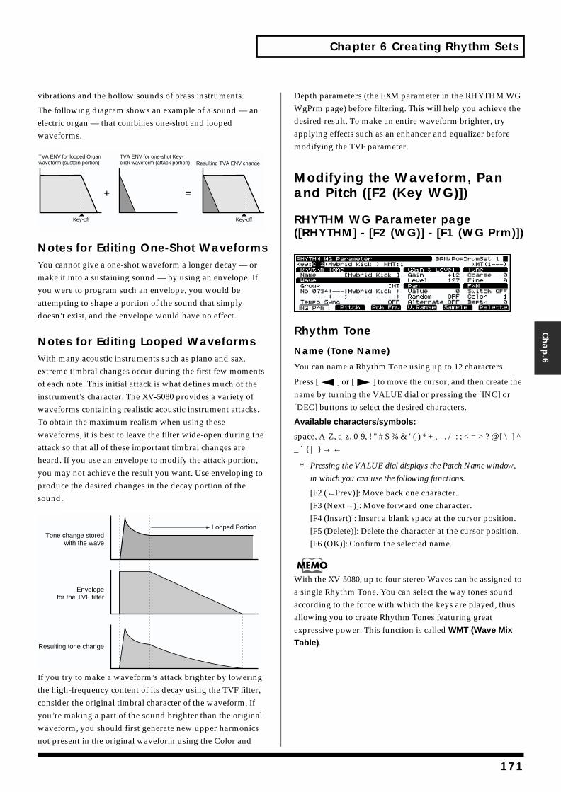
Chapter 6 Creating Rhythm Sets
Chap.6
vibrations and the hollow sounds of brass instruments.
The following diagram shows an example of a sound — an electric organ — that combines one-shot and looped waveforms.fig.06-005.e
Notes for Editing One-Shot WaveformsYou cannot give a one-shot waveform a longer decay — or make it into a sustaining sound — by using an envelope. If you were to program such an envelope, you would be attempting to shape a portion of the sound that simply doesn’t exist, and the envelope would have no effect.
Notes for Editing Looped WaveformsWith many acoustic instruments such as piano and sax, extreme timbral changes occur during the first few moments of each note. This initial attack is what defines much of the instrument’s character. The XV-5080 provides a variety of waveforms containing realistic acoustic instrument attacks. To obtain the maximum realism when using these waveforms, it is best to leave the filter wide-open during the attack so that all of these important timbral changes are heard. If you use an envelope to modify the attack portion, you may not achieve the result you want. Use enveloping to produce the desired changes in the decay portion of the sound.fig.06-006.e
If you try to make a waveform’s attack brighter by lowering the high-frequency content of its decay using the TVF filter, consider the original timbral character of the waveform. If you’re making a part of the sound brighter than the original waveform, you should first generate new upper harmonics not present in the original waveform using the Color and
Depth parameters (the FXM parameter in the RHYTHM WG WgPrm page) before filtering. This will help you achieve the desired result. To make an entire waveform brighter, try applying effects such as an enhancer and equalizer before modifying the TVF parameter.
Modifying the Waveform, Pan and Pitch ([F2 (Key WG)])
RHYTHM WG Parameter page ([RHYTHM] - [F2 (WG)] - [F1 (WG Prm)])fig.06-007.e_70
Rhythm Tone
Name (Tone Name)
You can name a Rhythm Tone using up to 12 characters.
Press [ ] or [ ] to move the cursor, and then create the name by turning the VALUE dial or pressing the [INC] or [DEC] buttons to select the desired characters.
Available characters/symbols:
space, A-Z, a-z, 0-9, ! " # $ % & ' ( ) * + , - . / : ; < = > ? @ [ \ ] ^ _ ` { | } → ←
* Pressing the VALUE dial displays the Patch Name window,
in which you can use the following functions.
[F2 (←Prev)]: Move back one character.[F3 (Next→)]: Move forward one character.[F4 (Insert)]: Insert a blank space at the cursor position.[F5 (Delete)]: Delete the character at the cursor position.[F6 (OK)]: Confirm the selected name.
With the XV-5080, up to four stereo Waves can be assigned to a single Rhythm Tone. You can select the way tones sound according to the force with which the keys are played, thus allowing you to create Rhythm Tones featuring great expressive power. This function is called WMT (Wave Mix
Table).
TVA ENV for looped Organ waveform (sustain portion)
Key-off
Resulting TVA ENV changeTVA ENV for one-shot Key-click waveform (attack portion)
Key-off
+ =
Tone change stored with the wave
Envelope for the TVF filter
Resulting tone change
Looped Portion
171
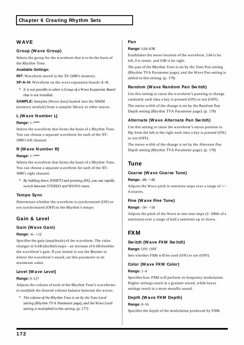
Chapter 6 Creating Rhythm Sets
WAVE
Group (Wave Group)
Selects the group for the waveform that is to be the basis of the Rhythm Tone.
Available Settings:
INT: Waveform stored in the XV-5080’s memory.
XP-A–H: Waveform on the wave expansion boards A–H.
* It is not possible to select a Group of a Wave Expansion Board
that is not installed.
SAMPLE: Samples (Wave data) loaded into the SIMM (memory module) from a sampler library or other source.
L (Wave Number L)
Range: 1–****
Selects the waveform that forms the basis of a Rhythm Tone. You can choose a separate waveform for each of the XV-5080’s left channel.
R (Wave Number R)
Range: 1–****
Selects the waveform that forms the basis of a Rhythm Tone. You can choose a separate waveform for each of the XV-5080’s right channel.
* By holding down [SHIFT] and pressing [F6], you can rapidly
switch between STEREO and MONO tones.
Tempo Sync
Determines whether the waveform is synchronized (ON) or not synchronized (OFF) to the Rhythm’s tempo.
Gain & Level
Gain (Wave Gain)
Range: -6– +12
Specifies the gain (amplitude) of the waveform. The value changes in 6 dB (decibel) steps—an increase of 6 dB doubles the waveform’s gain. If you intend to use the Booster to distort the waveform’s sound, set this parameter to its maximum value.
Level (Wave Level)
Range: 0–127
Adjusts the volume of each of the Rhythm Tone’s waveforms to establish the desired volume balance between the waves.
* The volume of the Rhythm Tone is set by the Tone Level
setting (Rhythm TVA Parameter page), and the Wave Level
setting is multiplied to this setting. (p. 177)
Pan
Range: L64–63R
Establishes the stereo location of the waveform. L64 is far left, 0 is center, and 63R is far right.
The pan of the Rhythm Tone is set by the Tone Pan setting (Rhythm TVA Parameter page), and the Wave Pan setting is added to this setting. (p. 178)
Random (Wave Random Pan Switch)
Use this setting to cause the waveform’s panning to change randomly each time a key is pressed (ON) or not (OFF).
The stereo width of the change is set by the Random Pan Depth setting (Rhythm TVA Parameter page). (p. 178)
Alternate (Wave Alternate Pan Switch)
Use this setting to cause the waveform’s stereo position to flip from the left to the right each time a key is pressed (ON) or not (OFF).
The stereo width of the change is set by the Alternate Pan Depth setting (Rhythm TVA Parameter page). (p. 178)
TuneCoarse (Wave Coarse Tune)
Range: -48– +48
Adjusts the Wave pitch in semitone steps over a range of +/-4 octaves.
Fine (Wave Fine Tune)
Range: -50– +50
Adjusts the pitch of the Wave in one-cent steps (1/100th of a semitone) over a range of half a semitone up or down.
FXMSwitch (Wave FXM Switch)
Range: ON/OFF
Sets whether FXM will be used (ON) or not (OFF).
Color (Wave FXM Color)
Range: 1–4
Specifies how FXM will perform its frequency modulation. Higher settings result in a grainier sound, while lower settings result in a more metallic sound.
Depth (Wave FXM Depth)
Range: 0–16
Specifies the depth of the modulation produced by FXM.
172
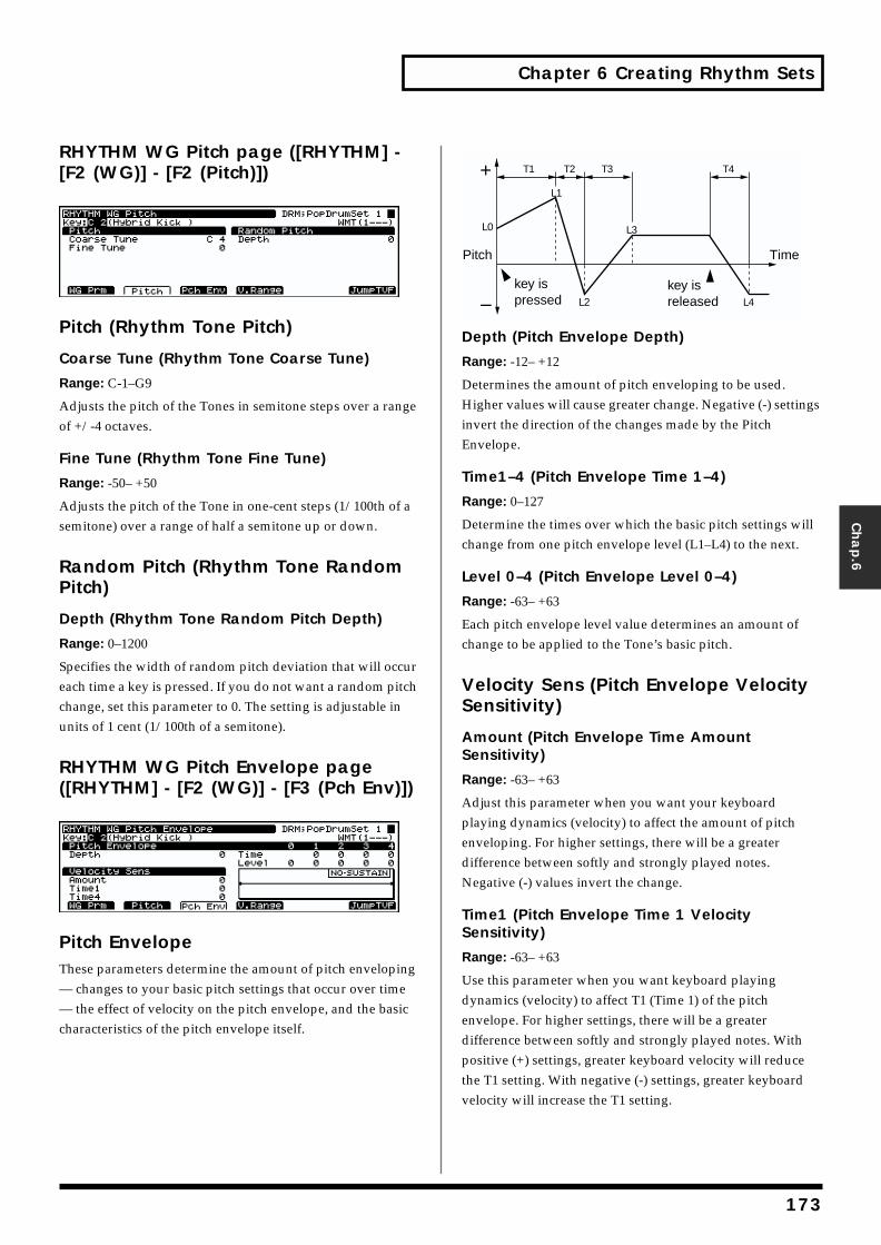
Chapter 6 Creating Rhythm Sets
Chap.6
RHYTHM WG Pitch page ([RHYTHM] - [F2 (WG)] - [F2 (Pitch)])fig.06-008.e_70
Pitch (Rhythm Tone Pitch)
Coarse Tune (Rhythm Tone Coarse Tune)
Range: C-1–G9
Adjusts the pitch of the Tones in semitone steps over a range of +/-4 octaves.
Fine Tune (Rhythm Tone Fine Tune)
Range: -50– +50
Adjusts the pitch of the Tone in one-cent steps (1/100th of a semitone) over a range of half a semitone up or down.
Random Pitch (Rhythm Tone Random Pitch)
Depth (Rhythm Tone Random Pitch Depth)
Range: 0–1200
Specifies the width of random pitch deviation that will occur each time a key is pressed. If you do not want a random pitch change, set this parameter to 0. The setting is adjustable in units of 1 cent (1/100th of a semitone).
RHYTHM WG Pitch Envelope page ([RHYTHM] - [F2 (WG)] - [F3 (Pch Env)])fig.06-009.e_70
Pitch EnvelopeThese parameters determine the amount of pitch enveloping — changes to your basic pitch settings that occur over time — the effect of velocity on the pitch envelope, and the basic characteristics of the pitch envelope itself.
fig.06-010.e
Depth (Pitch Envelope Depth)
Range: -12– +12
Determines the amount of pitch enveloping to be used. Higher values will cause greater change. Negative (-) settings invert the direction of the changes made by the Pitch Envelope.
Time1–4 (Pitch Envelope Time 1–4)
Range: 0–127
Determine the times over which the basic pitch settings will change from one pitch envelope level (L1–L4) to the next.
Level 0–4 (Pitch Envelope Level 0–4)
Range: -63– +63
Each pitch envelope level value determines an amount of change to be applied to the Tone’s basic pitch.
Velocity Sens (Pitch Envelope Velocity Sensitivity)
Amount (Pitch Envelope Time Amount Sensitivity)
Range: -63– +63
Adjust this parameter when you want your keyboard playing dynamics (velocity) to affect the amount of pitch enveloping. For higher settings, there will be a greater difference between softly and strongly played notes. Negative (-) values invert the change.
Time1 (Pitch Envelope Time 1 Velocity Sensitivity)
Range: -63– +63
Use this parameter when you want keyboard playing dynamics (velocity) to affect T1 (Time 1) of the pitch envelope. For higher settings, there will be a greater difference between softly and strongly played notes. With positive (+) settings, greater keyboard velocity will reduce the T1 setting. With negative (-) settings, greater keyboard velocity will increase the T1 setting.
T1 T2 T3 T4
L3
L4L2
L1
L0
Pitch
key ispressed
key isreleased
Time
173
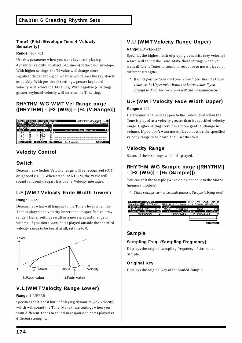
Chapter 6 Creating Rhythm Sets
Time4 (Pitch Envelope Time 4 Velocity Sensitivity)
Range: -63– +63
Use this parameter when you want keyboard playing dynamics (velocity) to affect T4 (Time 4) of the pitch envelope. With higher settings, the T4 value will change more significantly depending on whether you release the key slowly or quickly. With positive (+) settings, greater keyboard velocity will reduce the T4 setting. With negative (-) settings, greater keyboard velocity will increase the T4 setting.
RHYTHM WG WMT Vel Range page ([RHYTHM] - [F2 (WG)] - [F4 (V.Range)])fig.06-011.e_70
Velocity Control
SwitchDetermines whether Velocity range will be recognized (ON), or ignored (OFF). When set to RANDOM, the Wave will sound randomly, regardless of any Velocity messages.
L.F (WMT Velocity Fade Width Lower)Range: 0–127
Determines what will happen to the Tone’s level when the Tone is played at a velocity lower than its specified velocity range. Higher settings result in a more gradual change in volume. If you don’t want notes played outside the specified velocity range to be heard at all, set this to 0.fig.06-012.e
V.L (WMT Velocity Range Lower)Range: 1–UPPER
Specifies the highest limit of playing dynamics (key velocity) which will sound the Tone. Make these settings when you want different Tones to sound in response to notes played at different strengths.
V.U (WMT Velocity Range Upper)Range: LOWER–127
Specifies the highest limit of playing dynamics (key velocity) which will sound the Tone. Make these settings when you want different Tones to sound in response to notes played at different strengths.
* It is not possible to set the Lower value higher than the Upper
value, or the Upper value below the Lower value. If you
attempt to do so, the two values will change simultaneously.
U.F (WMT Velocity Fade Width Upper)Range: 0–127
Determines what will happen to the Tone’s level when the Tone is played at a velocity greater than its specified velocity range. Higher settings result in a more gradual change in volume. If you don’t want notes played outside the specified velocity range to be heard at all, set this to 0.
Velocity RangeStatus of these settings will be displayed.
RHYTHM WG Sample page ([RHYTHM] - [F2 (WG)] - [F5 (Sample)])You can edit the Sample (Wave data) loaded into the SIMM (memory module).
* These settings cannot be made unless a Sample is being used.fig.06-013.e_70
Sample
Sampling Freq. (Sampling Frequency)
Displays the original sampling frequency of the loaded Sample.
Original Key
Displays the original key of the loaded Sample.1
L.Fade value U.Fade value
Level
VelocityUpperLower
174
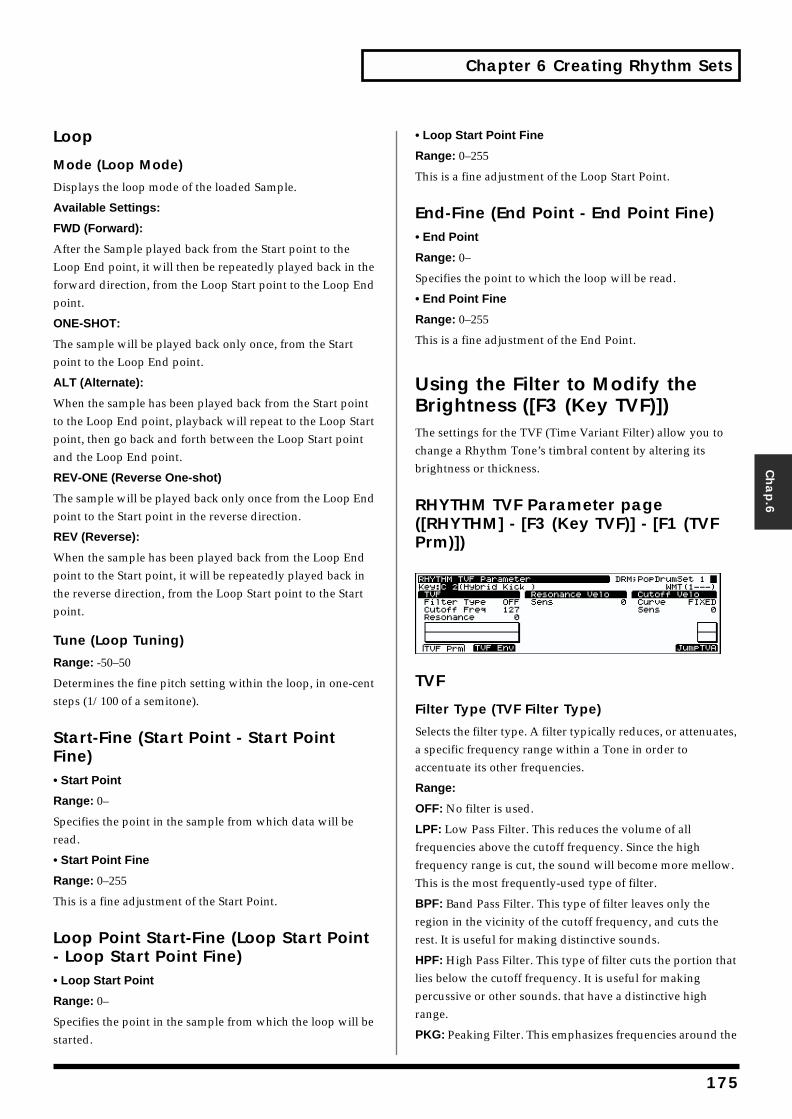
Chapter 6 Creating Rhythm Sets
Chap.6
Loop
Mode (Loop Mode)
Displays the loop mode of the loaded Sample.
Available Settings:
FWD (Forward):
After the Sample played back from the Start point to the Loop End point, it will then be repeatedly played back in the forward direction, from the Loop Start point to the Loop End point.
ONE-SHOT:
The sample will be played back only once, from the Start point to the Loop End point.
ALT (Alternate):
When the sample has been played back from the Start point to the Loop End point, playback will repeat to the Loop Start point, then go back and forth between the Loop Start point and the Loop End point.
REV-ONE (Reverse One-shot)
The sample will be played back only once from the Loop End point to the Start point in the reverse direction.
REV (Reverse):
When the sample has been played back from the Loop End point to the Start point, it will be repeatedly played back in the reverse direction, from the Loop Start point to the Start point.
Tune (Loop Tuning)
Range: -50–50
Determines the fine pitch setting within the loop, in one-cent steps (1/100 of a semitone).
Start-Fine (Start Point - Start Point Fine)• Start Point
Range: 0–
Specifies the point in the sample from which data will be read.
• Start Point Fine
Range: 0–255
This is a fine adjustment of the Start Point.
Loop Point Start-Fine (Loop Start Point - Loop Start Point Fine)• Loop Start Point
Range: 0–
Specifies the point in the sample from which the loop will be started.
• Loop Start Point Fine
Range: 0–255
This is a fine adjustment of the Loop Start Point.
End-Fine (End Point - End Point Fine)• End Point
Range: 0–
Specifies the point to which the loop will be read.
• End Point Fine
Range: 0–255
This is a fine adjustment of the End Point.
Using the Filter to Modify the Brightness ([F3 (Key TVF)])The settings for the TVF (Time Variant Filter) allow you to change a Rhythm Tone’s timbral content by altering its brightness or thickness.
RHYTHM TVF Parameter page ([RHYTHM] - [F3 (Key TVF)] - [F1 (TVF Prm)])fig.06-014.e_70
TVF
Filter Type (TVF Filter Type)
Selects the filter type. A filter typically reduces, or attenuates, a specific frequency range within a Tone in order to accentuate its other frequencies.
Range:
OFF: No filter is used.
LPF: Low Pass Filter. This reduces the volume of all frequencies above the cutoff frequency. Since the high frequency range is cut, the sound will become more mellow. This is the most frequently-used type of filter.
BPF: Band Pass Filter. This type of filter leaves only the region in the vicinity of the cutoff frequency, and cuts the rest. It is useful for making distinctive sounds.
HPF: High Pass Filter. This type of filter cuts the portion that lies below the cutoff frequency. It is useful for making percussive or other sounds. that have a distinctive high range.
PKG: Peaking Filter. This emphasizes frequencies around the
175
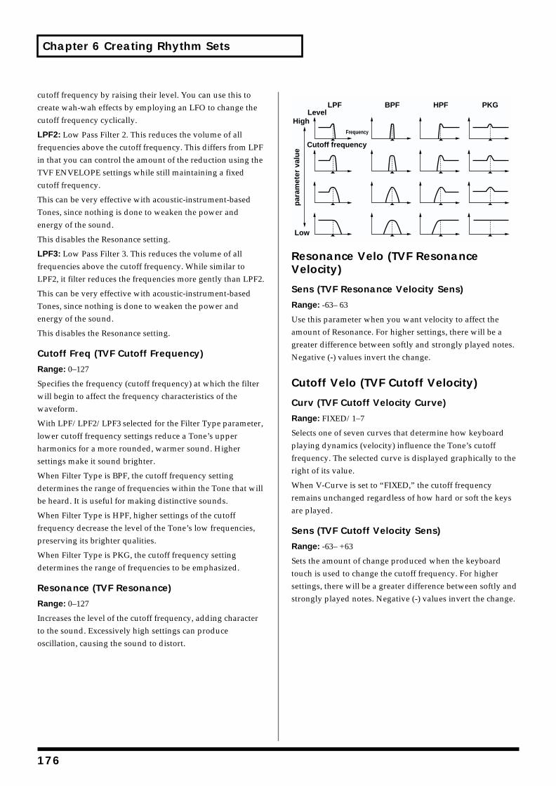
Chapter 6 Creating Rhythm Sets
cutoff frequency by raising their level. You can use this to create wah-wah effects by employing an LFO to change the cutoff frequency cyclically.
LPF2: Low Pass Filter 2. This reduces the volume of all frequencies above the cutoff frequency. This differs from LPF in that you can control the amount of the reduction using the TVF ENVELOPE settings while still maintaining a fixed cutoff frequency.
This can be very effective with acoustic-instrument-based Tones, since nothing is done to weaken the power and energy of the sound.
This disables the Resonance setting.
LPF3: Low Pass Filter 3. This reduces the volume of all frequencies above the cutoff frequency. While similar to LPF2, it filter reduces the frequencies more gently than LPF2.
This can be very effective with acoustic-instrument-based Tones, since nothing is done to weaken the power and energy of the sound.
This disables the Resonance setting.
Cutoff Freq (TVF Cutoff Frequency)
Range: 0–127
Specifies the frequency (cutoff frequency) at which the filter will begin to affect the frequency characteristics of the waveform.
With LPF/LPF2/LPF3 selected for the Filter Type parameter, lower cutoff frequency settings reduce a Tone’s upper harmonics for a more rounded, warmer sound. Higher settings make it sound brighter.
When Filter Type is BPF, the cutoff frequency setting determines the range of frequencies within the Tone that will be heard. It is useful for making distinctive sounds.
When Filter Type is HPF, higher settings of the cutoff frequency decrease the level of the Tone’s low frequencies, preserving its brighter qualities.
When Filter Type is PKG, the cutoff frequency setting determines the range of frequencies to be emphasized.
Resonance (TVF Resonance)
Range: 0–127
Increases the level of the cutoff frequency, adding character to the sound. Excessively high settings can produce oscillation, causing the sound to distort.
fig.06-015.e
Resonance Velo (TVF Resonance Velocity)
Sens (TVF Resonance Velocity Sens)
Range: -63– 63
Use this parameter when you want velocity to affect the amount of Resonance. For higher settings, there will be a greater difference between softly and strongly played notes. Negative (-) values invert the change.
Cutoff Velo (TVF Cutoff Velocity)
Curv (TVF Cutoff Velocity Curve)
Range: FIXED/1–7
Selects one of seven curves that determine how keyboard playing dynamics (velocity) influence the Tone’s cutoff frequency. The selected curve is displayed graphically to the right of its value.
When V-Curve is set to “FIXED,” the cutoff frequency remains unchanged regardless of how hard or soft the keys are played.
Sens (TVF Cutoff Velocity Sens)
Range: -63– +63
Sets the amount of change produced when the keyboard touch is used to change the cutoff frequency. For higher settings, there will be a greater difference between softly and strongly played notes. Negative (-) values invert the change.
LPF BPF HPF PKG
par
amet
er v
alu
e
Level
Cutoff frequency
Frequency
High
Low
176
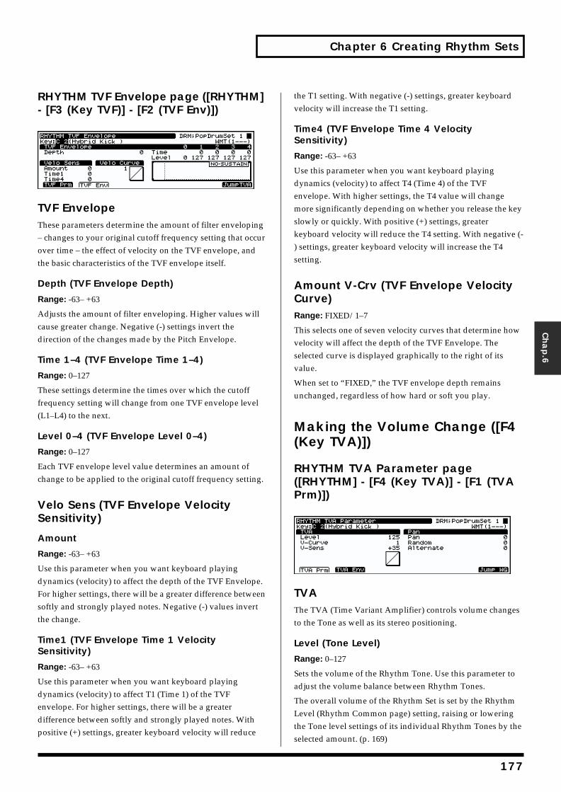
Chapter 6 Creating Rhythm Sets
Chap.6
RHYTHM TVF Envelope page ([RHYTHM] - [F3 (Key TVF)] - [F2 (TVF Env)])fig.06-016.e_70
TVF EnvelopeThese parameters determine the amount of filter enveloping – changes to your original cutoff frequency setting that occur over time – the effect of velocity on the TVF envelope, and the basic characteristics of the TVF envelope itself.
Depth (TVF Envelope Depth)
Range: -63– +63
Adjusts the amount of filter enveloping. Higher values will cause greater change. Negative (-) settings invert the direction of the changes made by the Pitch Envelope.
Time 1–4 (TVF Envelope Time 1–4)
Range: 0–127
These settings determine the times over which the cutoff frequency setting will change from one TVF envelope level (L1–L4) to the next.
Level 0–4 (TVF Envelope Level 0–4)
Range: 0–127
Each TVF envelope level value determines an amount of change to be applied to the original cutoff frequency setting.
Velo Sens (TVF Envelope Velocity Sensitivity)
Amount
Range: -63– +63
Use this parameter when you want keyboard playing dynamics (velocity) to affect the depth of the TVF Envelope. For higher settings, there will be a greater difference between softly and strongly played notes. Negative (-) values invert the change.
Time1 (TVF Envelope Time 1 Velocity Sensitivity)
Range: -63– +63
Use this parameter when you want keyboard playing dynamics (velocity) to affect T1 (Time 1) of the TVF envelope. For higher settings, there will be a greater difference between softly and strongly played notes. With positive (+) settings, greater keyboard velocity will reduce
the T1 setting. With negative (-) settings, greater keyboard velocity will increase the T1 setting.
Time4 (TVF Envelope Time 4 Velocity Sensitivity)
Range: -63– +63
Use this parameter when you want keyboard playing dynamics (velocity) to affect T4 (Time 4) of the TVF envelope. With higher settings, the T4 value will change more significantly depending on whether you release the key slowly or quickly. With positive (+) settings, greater keyboard velocity will reduce the T4 setting. With negative (-) settings, greater keyboard velocity will increase the T4 setting.
Amount V-Crv (TVF Envelope Velocity Curve)Range: FIXED/1–7
This selects one of seven velocity curves that determine how velocity will affect the depth of the TVF Envelope. The selected curve is displayed graphically to the right of its value.
When set to “FIXED,” the TVF envelope depth remains unchanged, regardless of how hard or soft you play.
Making the Volume Change ([F4 (Key TVA)])
RHYTHM TVA Parameter page ([RHYTHM] - [F4 (Key TVA)] - [F1 (TVA Prm)])fig.06-017.e_70
TVAThe TVA (Time Variant Amplifier) controls volume changes to the Tone as well as its stereo positioning.
Level (Tone Level)
Range: 0–127
Sets the volume of the Rhythm Tone. Use this parameter to adjust the volume balance between Rhythm Tones.
The overall volume of the Rhythm Set is set by the Rhythm Level (Rhythm Common page) setting, raising or lowering the Tone level settings of its individual Rhythm Tones by the selected amount. (p. 169)
177
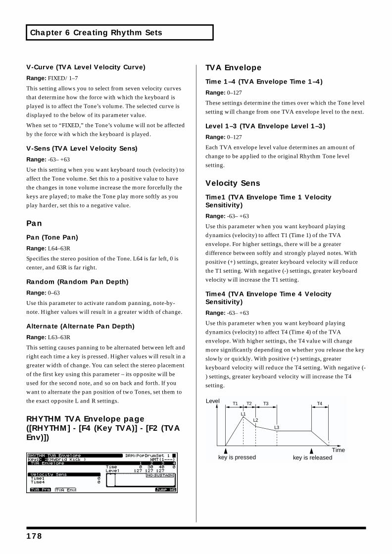
Chapter 6 Creating Rhythm Sets
V-Curve (TVA Level Velocity Curve)
Range: FIXED/1–7
This setting allows you to select from seven velocity curves that determine how the force with which the keyboard is played is to affect the Tone’s volume. The selected curve is displayed to the below of its parameter value.
When set to “FIXED,” the Tone’s volume will not be affected by the force with which the keyboard is played.
V-Sens (TVA Level Velocity Sens)
Range: -63– +63
Use this setting when you want keyboard touch (velocity) to affect the Tone volume. Set this to a positive value to have the changes in tone volume increase the more forcefully the keys are played; to make the Tone play more softly as you play harder, set this to a negative value.
Pan
Pan (Tone Pan)
Range: L64–63R
Specifies the stereo position of the Tone. L64 is far left, 0 is center, and 63R is far right.
Random (Random Pan Depth)
Range: 0–63
Use this parameter to activate random panning, note-by-note. Higher values will result in a greater width of change.
Alternate (Alternate Pan Depth)
Range: L63–63R
This setting causes panning to be alternated between left and right each time a key is pressed. Higher values will result in a greater width of change. You can select the stereo placement of the first key using this parameter – its opposite will be used for the second note, and so on back and forth. If you want to alternate the pan position of two Tones, set them to the exact opposite L and R settings.
RHYTHM TVA Envelope page ([RHYTHM] - [F4 (Key TVA)] - [F2 (TVA Env)])fig.06-018.e_70
TVA Envelope
Time 1–4 (TVA Envelope Time 1–4)
Range: 0–127
These settings determine the times over which the Tone level setting will change from one TVA envelope level to the next.
Level 1–3 (TVA Envelope Level 1–3)
Range: 0–127
Each TVA envelope level value determines an amount of change to be applied to the original Rhythm Tone level setting.
Velocity Sens
Time1 (TVA Envelope Time 1 Velocity Sensitivity)
Range: -63– +63
Use this parameter when you want keyboard playing dynamics (velocity) to affect T1 (Time 1) of the TVA envelope. For higher settings, there will be a greater difference between softly and strongly played notes. With positive (+) settings, greater keyboard velocity will reduce the T1 setting. With negative (-) settings, greater keyboard velocity will increase the T1 setting.
Time4 (TVA Envelope Time 4 Velocity Sensitivity)
Range: -63– +63
Use this parameter when you want keyboard playing dynamics (velocity) to affect T4 (Time 4) of the TVA envelope. With higher settings, the T4 value will change more significantly depending on whether you release the key slowly or quickly. With positive (+) settings, greater keyboard velocity will reduce the T4 setting. With negative (-) settings, greater keyboard velocity will increase the T4 setting.fig.06-019.e
T1 T2 T3 T4
L3
L1L2
Level
key is pressed key is releasedTime
178
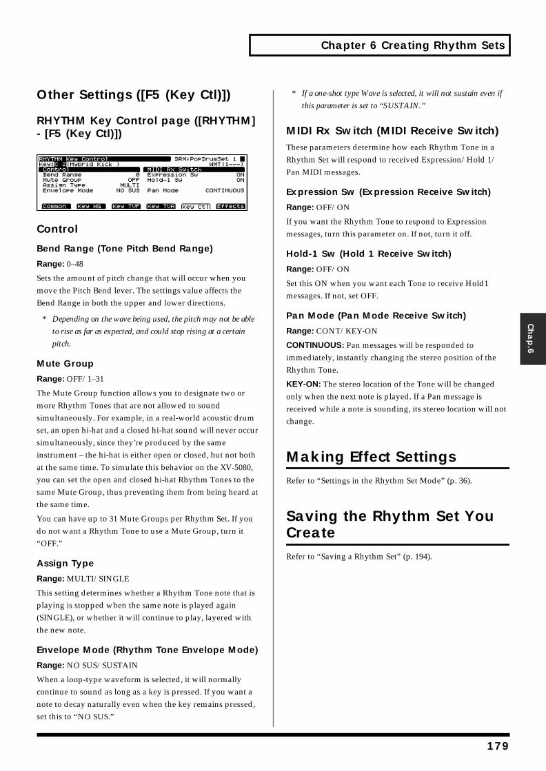
Chapter 6 Creating Rhythm Sets
Chap.6
Other Settings ([F5 (Key Ctl)])
RHYTHM Key Control page ([RHYTHM] - [F5 (Key Ctl)])fig.06-020.e_70
Control
Bend Range (Tone Pitch Bend Range)
Range: 0–48
Sets the amount of pitch change that will occur when you move the Pitch Bend lever. The settings value affects the Bend Range in both the upper and lower directions.
* Depending on the wave being used, the pitch may not be able
to rise as far as expected, and could stop rising at a certain
pitch.
Mute Group
Range: OFF/1–31
The Mute Group function allows you to designate two or more Rhythm Tones that are not allowed to sound simultaneously. For example, in a real-world acoustic drum set, an open hi-hat and a closed hi-hat sound will never occur simultaneously, since they’re produced by the same instrument – the hi-hat is either open or closed, but not both at the same time. To simulate this behavior on the XV-5080, you can set the open and closed hi-hat Rhythm Tones to the same Mute Group, thus preventing them from being heard at the same time.
You can have up to 31 Mute Groups per Rhythm Set. If you do not want a Rhythm Tone to use a Mute Group, turn it “OFF.”
Assign Type
Range: MULTI/SINGLE
This setting determines whether a Rhythm Tone note that is playing is stopped when the same note is played again (SINGLE), or whether it will continue to play, layered with the new note.
Envelope Mode (Rhythm Tone Envelope Mode)
Range: NO SUS/SUSTAIN
When a loop-type waveform is selected, it will normally continue to sound as long as a key is pressed. If you want a note to decay naturally even when the key remains pressed, set this to “NO SUS.”
* If a one-shot type Wave is selected, it will not sustain even if
this parameter is set to “SUSTAIN.”
MIDI Rx Switch (MIDI Receive Switch)These parameters determine how each Rhythm Tone in a Rhythm Set will respond to received Expression/Hold 1/Pan MIDI messages.
Expression Sw (Expression Receive Switch)
Range: OFF/ON
If you want the Rhythm Tone to respond to Expression messages, turn this parameter on. If not, turn it off.
Hold-1 Sw (Hold 1 Receive Switch)
Range: OFF/ON
Set this ON when you want each Tone to receive Hold1 messages. If not, set OFF.
Pan Mode (Pan Mode Receive Switch)
Range: CONT/KEY-ON
CONTINUOUS: Pan messages will be responded to immediately, instantly changing the stereo position of the Rhythm Tone.
KEY-ON: The stereo location of the Tone will be changed only when the next note is played. If a Pan message is received while a note is sounding, its stereo location will not change.
Making Effect SettingsRefer to “Settings in the Rhythm Set Mode” (p. 36).
Saving the Rhythm Set You CreateRefer to “Saving a Rhythm Set” (p. 194).
179
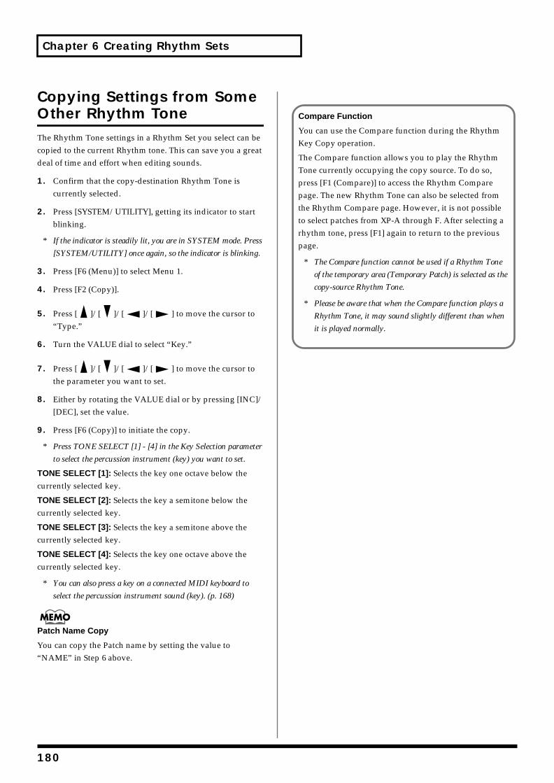
Chapter 6 Creating Rhythm Sets
Copying Settings from Some Other Rhythm ToneThe Rhythm Tone settings in a Rhythm Set you select can be copied to the current Rhythm tone. This can save you a great deal of time and effort when editing sounds.
1. Confirm that the copy-destination Rhythm Tone is currently selected.
2. Press [SYSTEM/UTILITY], getting its indicator to start blinking.
* If the indicator is steadily lit, you are in SYSTEM mode. Press
[SYSTEM/UTILITY] once again, so the indicator is blinking.
3. Press [F6 (Menu)] to select Menu 1.
4. Press [F2 (Copy)].
5. Press [ ]/[ ]/[ ]/[ ] to move the cursor to “Type.”
6. Turn the VALUE dial to select “Key.”
7. Press [ ]/[ ]/[ ]/[ ] to move the cursor to the parameter you want to set.
8. Either by rotating the VALUE dial or by pressing [INC]/[DEC], set the value.
9. Press [F6 (Copy)] to initiate the copy.
* Press TONE SELECT [1] - [4] in the Key Selection parameter
to select the percussion instrument (key) you want to set.
TONE SELECT [1]: Selects the key one octave below the currently selected key.
TONE SELECT [2]: Selects the key a semitone below the currently selected key.
TONE SELECT [3]: Selects the key a semitone above the currently selected key.
TONE SELECT [4]: Selects the key one octave above the currently selected key.
* You can also press a key on a connected MIDI keyboard to
select the percussion instrument sound (key). (p. 168)
Patch Name Copy
You can copy the Patch name by setting the value to “NAME” in Step 6 above.
Compare Function
You can use the Compare function during the Rhythm Key Copy operation.
The Compare function allows you to play the Rhythm Tone currently occupying the copy source. To do so, press [F1 (Compare)] to access the Rhythm Compare page. The new Rhythm Tone can also be selected from the Rhythm Compare page. However, it is not possible to select patches from XP-A through F. After selecting a rhythm tone, press [F1] again to return to the previous page.
* The Compare function cannot be used if a Rhythm Tone
of the temporary area (Temporary Patch) is selected as the
copy-source Rhythm Tone.
* Please be aware that when the Compare function plays a
Rhythm Tone, it may sound slightly different than when
it is played normally.
180
Chapter 7 Loading a Variety of Data
Loading Sampler Libraries (CD-ROM)Now let’s try loading a sampler library (such as the optional L-CDX Series) into the XV-5080 and playing some sounds.
Playing sampler libraries with the XV-5080 requires a SCSI-type CD-ROM drive (the optional CDR-88RW-2), and commercially available SIMMs (memory modules).
* At least 16 MB (32 MB or more recommended) of additional
memory is required.
The AKAI S1000/3000 CD-ROM sound libraries can also be loaded. (p. 187)
Installing the SIMM (Memory Module)Loading commercial sampler libraries into the XV-5080 requires installation of a SIMM memory module. The XV-5080 is equipped with two slots for SIMMs, allowing you to expand memory capacity by 128 MB (with two 64-megabyte SIMMs installed).
SIMMs for use with the XV-5080 must match the
following specifications.
Number of pins: 72
Access time: 60 ns or faster
Access protocol: FPM or EDO
Voltage: 5 V
Capacity: 64 MB/32 MB/16 MB (can be mixed)
*Both parity and non-parity are supported.
SIMM height: 36 mm or less
Cautions When Installing SIMMTo avoid the risk of damage to internal components that can be caused by static electricity, please carefully observe the following whenever you handle the board.
• Before you touch the board, always first grasp a metal object (such as a water pipe), so you are sure that any static electricity you might have been carrying has been discharged.
• When handling the board, grasp it only by its edges. Avoid touching any of the electronic components or connectors.
• Save the bag in which the board was originally shipped, and put the board back into it whenever you need to store or transport it.
Use a Philips screwdriver that is suitable for the size of the screw. If an unsuitable screwdriver is used, the head of the screw may be stripped.
To remove a screw, rotate the screwdriver counter-clockwise. To tighten the screws, rotate the screwdriver clockwise.fig.07-001.e
• Be careful not to cut your hands on the edges of the opening while removing the cover.
• When adding SIMMs, remove only the specified screws.
• Be careful that the screws you remove do not drop into the interior of the XV-5080.
• Do not touch any of the printed circuit pathways or connection terminals.
• Never use excessive force when installing a circuit board. If it doesn’t fit properly on the first attempt, remove the board and try again.
• When circuit board installation is complete, double-check your work.
• Do not leave the cover removed. Be sure to reattach it after the SIMM has been installed.
tightenloosen
181
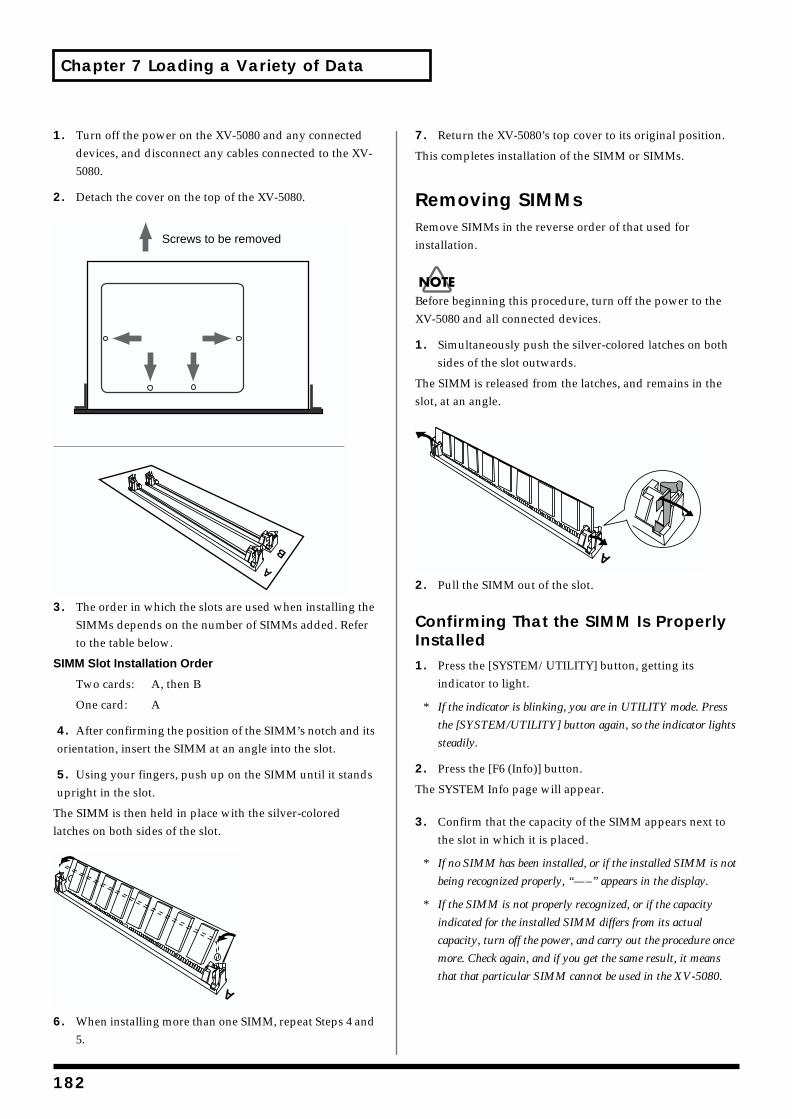
Chapter 7 Loading a Variety of Data
1. Turn off the power on the XV-5080 and any connected devices, and disconnect any cables connected to the XV-5080.
2. Detach the cover on the top of the XV-5080.fig.07-002.e
3. The order in which the slots are used when installing the SIMMs depends on the number of SIMMs added. Refer to the table below.
SIMM Slot Installation Order
Two cards: A, then B
One card: A
4. After confirming the position of the SIMM’s notch and its orientation, insert the SIMM at an angle into the slot.
5. Using your fingers, push up on the SIMM until it stands upright in the slot.
The SIMM is then held in place with the silver-colored latches on both sides of the slot.fig.07-003.e
6. When installing more than one SIMM, repeat Steps 4 and 5.
7. Return the XV-5080’s top cover to its original position.
This completes installation of the SIMM or SIMMs.
Removing SIMMsRemove SIMMs in the reverse order of that used for installation.
Before beginning this procedure, turn off the power to the XV-5080 and all connected devices.
1. Simultaneously push the silver-colored latches on both sides of the slot outwards.
The SIMM is released from the latches, and remains in the slot, at an angle.fig.07-004.e
2. Pull the SIMM out of the slot.
Confirming That the SIMM Is Properly Installed1. Press the [SYSTEM/UTILITY] button, getting its
indicator to light.
* If the indicator is blinking, you are in UTILITY mode. Press
the [SYSTEM/UTILITY] button again, so the indicator lights
steadily.
2. Press the [F6 (Info)] button.
The SYSTEM Info page will appear.
3. Confirm that the capacity of the SIMM appears next to the slot in which it is placed.
* If no SIMM has been installed, or if the installed SIMM is not
being recognized properly, “—–” appears in the display.
* If the SIMM is not properly recognized, or if the capacity
indicated for the installed SIMM differs from its actual
capacity, turn off the power, and carry out the procedure once
more. Check again, and if you get the same result, it means
that that particular SIMM cannot be used in the XV-5080.
A
B
Screws to be removed
A
A
182
Chapter 7 Loading a Variety of Data
Chap.7
Installation de la carte d'extension Wave (French language for Canadian Safety Standard)
Les cartes d'exten-sion Wave contiennent des donnees Wave, aussi bien que des morceaux musicaux et des ensembles rythmiques utilisant ces donnees, auxquelles on peut directement acceder dans la zone temporaire et les faire jouer.
Precautions lors de l'installation de la carte d'extension Wave
• Pour éviter tout dommage des composants internes pouvant provenir de l’électricité statique, veuillez suivre les conseils suivants quand vous installez la carte.
* Avant de toucher la carte, saisissez toujours un objet
métallique (tuyau d’eau ou autre) pour être sûr que
l’électricité statique se décharge.
* Quand vous saisissez la carte, prenez-la par les bords. Evitez
de toucher les composants électroniques ou les connecteurs.
* Conservez le sac dans lequel la carte était emballée et remettez
la carte dedans pour l’expédier ou l’entreposer.
• Utiliser un tournevis cruciforme correspondant à la taille de la vis (un tournevis numéro 2). En cas d’utilisation d’un tournevis inapproprié, la tête de la vis pourrait être endommagée.
• Pour enlever les vis, tourner le tournevis dans le sens contraire des aiguilles d’une montre. Pour resserrer, tourner dans le sens des aiguilles d’une montre.
• Lors de l’insertion de la carte d’extension Wave, enlevez seulement les vis indiquées dans les instructions.
• Veillez à ne pas laisser tomber de vis dans le châssis du XV-5080.
• Ne pas laisser le panneau de protection avant détaché. S’assurer de l’avoir rattacher après avoir installé le disque dur.
• Ne touchez aucun des circuits imprimés ni les bornes de connexion.
• Veillez à ne pas vous couper les doitgs sur le bord de l’ouverture d’installation.
• Ne jamais forcer quand vous installez une carte de circuits. Si la carte ne rentre pas correctement, ressortez-la et ressayez.
• Quand la carte est installée, vérifiez si l’installation est correcte.
Pour installer une carte d'extension (vendue en option dans les séries SR-JV80 et SRX), détacher la plaque du dessus. La carte de série SRX s'installe dans l'emplacement EXP-E,F et la carte de série SR-JV80, dans l'emplacement EXP-A–D.
resserrerdesserrer
183
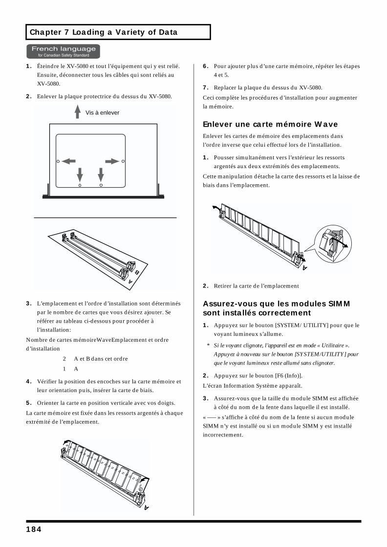
Chapter 7 Loading a Variety of Data
1. Éteindre le XV-5080 et tout l’équipement qui y est relié. Ensuite, déconnecter tous les câbles qui sont reliés au XV-5080.
2. Enlever la plaque protectrice du dessus du XV-5080.
3. L’emplacement et l’ordre d’installation sont déterminés par le nombre de cartes que vous désirez ajouter. Se référer au tableau ci-dessous pour procéder à l’installation:
Nombre de cartes mémoireWaveEmplacement et ordre d’installation
2 A et B dans cet ordre
1 A
4. Vérifier la position des encoches sur la carte mémoire et leur orientation puis, insérer la carte de biais.
5. Orienter la carte en position verticale avec vos doigts.
La carte mémoire est fixée dans les ressorts argentés à chaque extrémité de l’emplacement.
6. Pour ajouter plus d’une carte mémoire, répéter les étapes 4 et 5.
7. Replacer la plaque du dessus du XV-5080.
Ceci complète les procédures d’installation pour augmenter la mémoire.
Enlever une carte mémoire WaveEnlever les cartes de mémoire des emplacements dans l’ordre inverse que celui effectué lors de l’installation.
1. Pousser simultanément vers l’extérieur les ressorts argentés aux deux extrémités des emplacements.
Cette manipulation détache la carte des ressorts et la laisse de biais dans l’emplacement.
2. Retirer la carte de l’emplacement
Assurez-vous que les modules SIMM sont installés correctement1. Appuyez sur le bouton [SYSTEM/UTILITY] pour que le
voyant lumineux s’allume.
* Si le voyant clignote, l’appareil est en mode « Utilitaire ».
Appuyez à nouveau sur le bouton [SYSTEM/UTILITY] pour
que le voyant lumineux reste allumé sans clignoter.
2. Appuyez sur le bouton [F6 (Info)].
L’écran Information Système apparaît.
3. Assurez-vous que la taille du module SIMM est affichée à côté du nom de la fente dans laquelle il est installé.
« —– » s’affiche à côté du nom de la fente si aucun module SIMM n’y est installé ou si un module SIMM y est installé incorrectement.
A
B
Vis à enlever
A
A
184
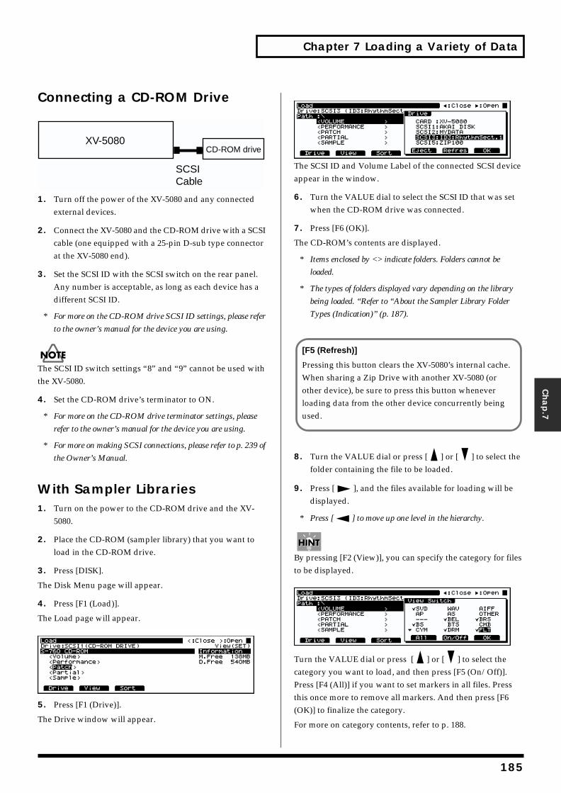
Chapter 7 Loading a Variety of Data
Chap.7
Connecting a CD-ROM Drivefig.07-005.e
1. Turn off the power of the XV-5080 and any connected external devices.
2. Connect the XV-5080 and the CD-ROM drive with a SCSI cable (one equipped with a 25-pin D-sub type connector at the XV-5080 end).
3. Set the SCSI ID with the SCSI switch on the rear panel. Any number is acceptable, as long as each device has a different SCSI ID.
* For more on the CD-ROM drive SCSI ID settings, please refer
to the owner’s manual for the device you are using.
The SCSI ID switch settings “8” and “9” cannot be used with the XV-5080.
4. Set the CD-ROM drive’s terminator to ON.
* For more on the CD-ROM drive terminator settings, please
refer to the owner’s manual for the device you are using.
* For more on making SCSI connections, please refer to p. 239 of
the Owner’s Manual.
With Sampler Libraries1. Turn on the power to the CD-ROM drive and the XV-
5080.
2. Place the CD-ROM (sampler library) that you want to load in the CD-ROM drive.
3. Press [DISK].
The Disk Menu page will appear.
4. Press [F1 (Load)].
The Load page will appear.fig.07-006.e_70
5. Press [F1 (Drive)].
The Drive window will appear.
fig.07-007.e_70
The SCSI ID and Volume Label of the connected SCSI device appear in the window.
6. Turn the VALUE dial to select the SCSI ID that was set when the CD-ROM drive was connected.
7. Press [F6 (OK)].
The CD-ROM’s contents are displayed.
* Items enclosed by <> indicate folders. Folders cannot be
loaded.
* The types of folders displayed vary depending on the library
being loaded. “Refer to “About the Sampler Library Folder
Types (Indication)” (p. 187).
8. Turn the VALUE dial or press [ ] or [ ] to select the folder containing the file to be loaded.
9. Press [ ], and the files available for loading will be displayed.
* Press [ ] to move up one level in the hierarchy.
By pressing [F2 (View)], you can specify the category for files to be displayed.fig.07-008.e_70
Turn the VALUE dial or press [ ] or [ ] to select the category you want to load, and then press [F5 (On/Off)]. Press [F4 (All)] if you want to set markers in all files. Press this once more to remove all markers. And then press [F6 (OK)] to finalize the category.
For more on category contents, refer to p. 188.
XV-5080CD-ROM drive
SCSICable
[F5 (Refresh)]
Pressing this button clears the XV-5080’s internal cache. When sharing a Zip Drive with another XV-5080 (or other device), be sure to press this button whenever loading data from the other device concurrently being used.
185
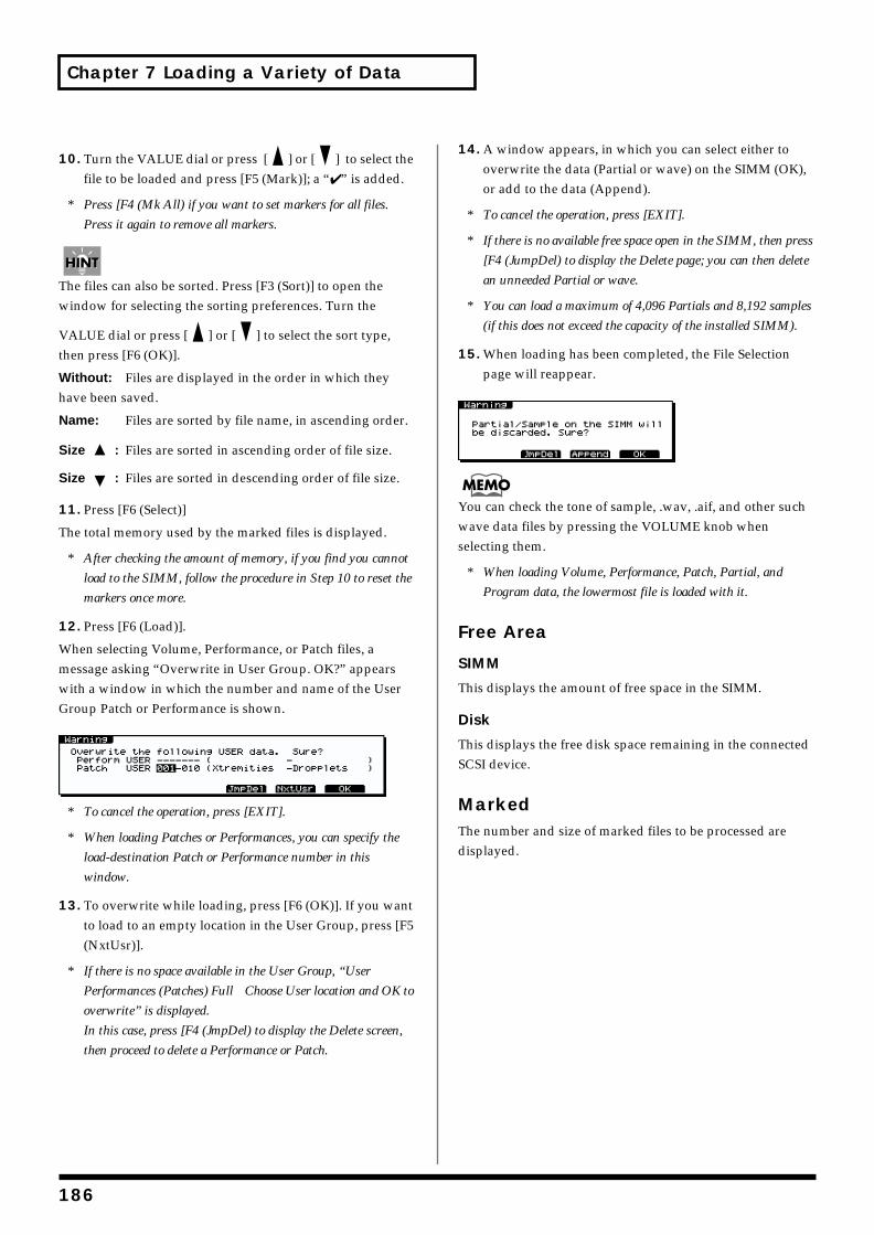
Chapter 7 Loading a Variety of Data
10. Turn the VALUE dial or press [ ] or [ ] to select the file to be loaded and press [F5 (Mark)]; a “✔ ” is added.
* Press [F4 (Mk All) if you want to set markers for all files.
Press it again to remove all markers.
The files can also be sorted. Press [F3 (Sort)] to open the window for selecting the sorting preferences. Turn the
VALUE dial or press [ ] or [ ] to select the sort type, then press [F6 (OK)].
Without: Files are displayed in the order in which they have been saved.
Name: Files are sorted by file name, in ascending order.
Size : Files are sorted in ascending order of file size.
Size : Files are sorted in descending order of file size.
11. Press [F6 (Select)]
The total memory used by the marked files is displayed.
* After checking the amount of memory, if you find you cannot
load to the SIMM, follow the procedure in Step 10 to reset the
markers once more.
12. Press [F6 (Load)].
When selecting Volume, Performance, or Patch files, a message asking “Overwrite in User Group. OK?” appears with a window in which the number and name of the User Group Patch or Performance is shown.fig.07-009.e_70
* To cancel the operation, press [EXIT].
* When loading Patches or Performances, you can specify the
load-destination Patch or Performance number in this
window.
13. To overwrite while loading, press [F6 (OK)]. If you want to load to an empty location in the User Group, press [F5 (NxtUsr)].
* If there is no space available in the User Group, “User
Performances (Patches) Full Choose User location and OK to
overwrite” is displayed.
In this case, press [F4 (JmpDel) to display the Delete screen,
then proceed to delete a Performance or Patch.
14. A window appears, in which you can select either to overwrite the data (Partial or wave) on the SIMM (OK), or add to the data (Append).
* To cancel the operation, press [EXIT].
* If there is no available free space open in the SIMM, then press
[F4 (JumpDel) to display the Delete page; you can then delete
an unneeded Partial or wave.
* You can load a maximum of 4,096 Partials and 8,192 samples
(if this does not exceed the capacity of the installed SIMM).
15. When loading has been completed, the File Selection page will reappear.
fig.07-010.e_70
You can check the tone of sample, .wav, .aif, and other such wave data files by pressing the VOLUME knob when selecting them.
* When loading Volume, Performance, Patch, Partial, and
Program data, the lowermost file is loaded with it.
Free Area
SIMM
This displays the amount of free space in the SIMM.
Disk
This displays the free disk space remaining in the connected SCSI device.
MarkedThe number and size of marked files to be processed are displayed.
186
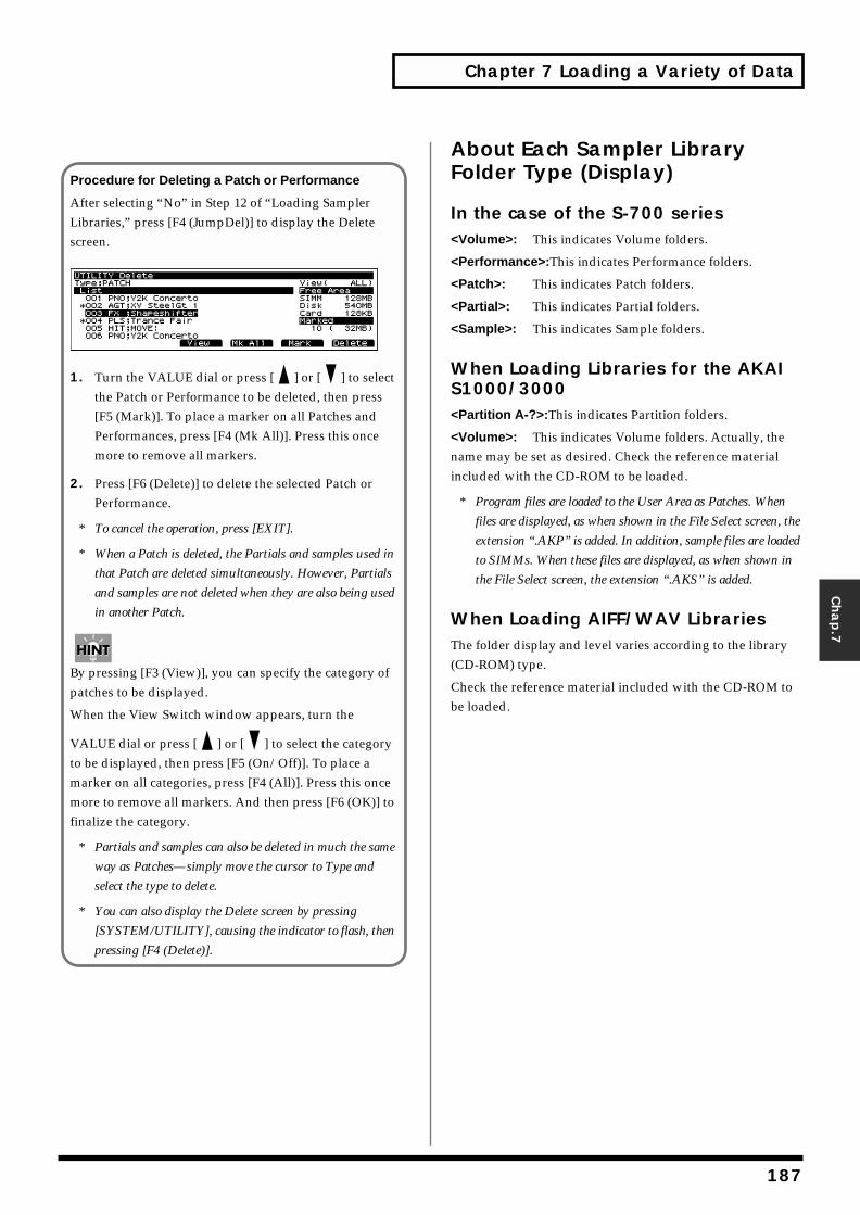
Chapter 7 Loading a Variety of Data
Chap.7
About Each Sampler Library Folder Type (Display)
In the case of the S-700 series<Volume>: This indicates Volume folders.
<Performance>:This indicates Performance folders.
<Patch>: This indicates Patch folders.
<Partial>: This indicates Partial folders.
<Sample>: This indicates Sample folders.
When Loading Libraries for the AKAI S1000/3000<Partition A-?>:This indicates Partition folders.
<Volume>: This indicates Volume folders. Actually, the name may be set as desired. Check the reference material included with the CD-ROM to be loaded.
* Program files are loaded to the User Area as Patches. When
files are displayed, as when shown in the File Select screen, the
extension “.AKP” is added. In addition, sample files are loaded
to SIMMs. When these files are displayed, as when shown in
the File Select screen, the extension “.AKS” is added.
When Loading AIFF/WAV LibrariesThe folder display and level varies according to the library (CD-ROM) type.
Check the reference material included with the CD-ROM to be loaded.
Procedure for Deleting a Patch or Performance
After selecting “No” in Step 12 of “Loading Sampler Libraries,” press [F4 (JumpDel)] to display the Delete screen.fig.07-01.e_65
1. Turn the VALUE dial or press [ ] or [ ] to select the Patch or Performance to be deleted, then press [F5 (Mark)]. To place a marker on all Patches and Performances, press [F4 (Mk All)]. Press this once more to remove all markers.
2. Press [F6 (Delete)] to delete the selected Patch or Performance.
* To cancel the operation, press [EXIT].
* When a Patch is deleted, the Partials and samples used in
that Patch are deleted simultaneously. However, Partials
and samples are not deleted when they are also being used
in another Patch.
By pressing [F3 (View)], you can specify the category of patches to be displayed.
When the View Switch window appears, turn the
VALUE dial or press [ ] or [ ] to select the category to be displayed, then press [F5 (On/Off)]. To place a marker on all categories, press [F4 (All)]. Press this once more to remove all markers. And then press [F6 (OK)] to finalize the category.
* Partials and samples can also be deleted in much the same
way as Patches—simply move the cursor to Type and
select the type to delete.
* You can also display the Delete screen by pressing
[SYSTEM/UTILITY], causing the indicator to flash, then
pressing [F4 (Delete)].
187
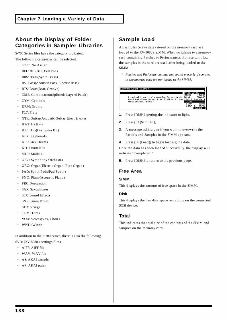
Chapter 7 Loading a Variety of Data
About the Display of Folder Categories in Sampler LibrariesS-700 Series files have the category indicated.
The following categories can be selected.
• other: No Assign
• BEL: Bell(Bell, Bell Pad)
• BRS: Brass(Synth Brass)
• BS : Bass(Acoustic Bass, Electric Bass)
• BTS: Beats(Beat, Groove)
• CMB: Combination(Splitted/Layerd Patch)
• CYM: Cymbals
• DRM: Drums
• FLT: Flute
• GTR: Guitar(Acoustic Guitar, Electric uitar
• HAT: Hi Hats
• HIT: Hits(Orchestra Hit)
• KEY: Keyboards
• KIK: Kick Drums
• KIT: Drum Kits
• MLT: Mallets
• ORC: Symphony Orchestra
• ORG: Organ(Electric Organ, Pipe Organ)
• PAD: Synth Pads(Pad Synth)
• PNO: Piano(Acoustic Piano)
• PRC: Percussion
• SAX: Saxophones
• SFX: Sound Effects
• SNR: Snare Drum
• STR: Strings
• TOM: Toms
• VOX: Voices(Vox, Choir)
• WND: Winds
In addition to the S-700 Series, there is also the following.
SVD: (XV-5080's settings files)
• AIFF: AIFF file
• WAV: WAV file
• AS: AKAI sample
• AP: AKAI patch
Sample LoadAll samples (wave data) stored on the memory card are loaded to the XV-5080’s SIMM. When switching to a memory card containing Patches or Performances that use samples, the samples in the card are used after being loaded to the SIMM.
* Patches and Performances may not sound properly if samples
in the inserted card are not loaded to the SIMM.fig.07-02.e_70
1. Press [DISK], getting the indicator to light.
2. Press [F3 (SampLd)].
3. A message asking you if you want to overwrite the Partials and Samples in the SIMM appears.
4. Press [F6 (Load)] to begin loading the data.
Once the data has been loaded successfully, the display will indicate “Completed!”
5. Press [DISK] to return to the previous page.
Free Area
SIMM
This displays the amount of free space in the SIMM.
Disk
This displays the free disk space remaining on the connected SCSI device.
TotalThis indicates the total size of the contents of the SIMM and samples on the memory card.
188
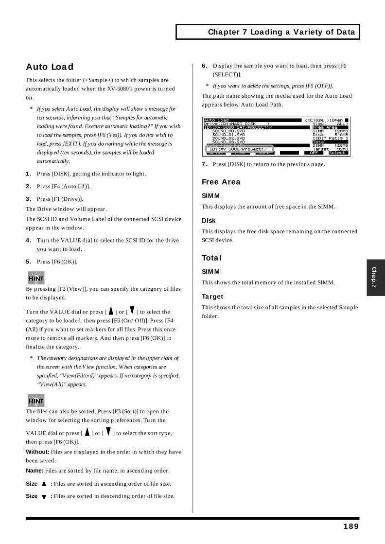
Chapter 7 Loading a Variety of Data
Chap.7
Auto LoadThis selects the folder (<Sample>) to which samples are automatically loaded when the XV-5080’s power is turned on.
* If you select Auto Load, the display will show a message for
ten seconds, informing you that “Samples for automatic
loading were found. Execute automatic loading?” If you wish
to load the samples, press [F6 (Yes)]. If you do not wish to
load, press [EXIT]. If you do nothing while the message is
displayed (ten seconds), the samples will be loaded
automatically.
1. Press [DISK], getting the indicator to light.
2. Press [F4 (Auto Ld)].
3. Press [F1 (Drive)].
The Drive window will appear.
The SCSI ID and Volume Label of the connected SCSI device appear in the window.
4. Turn the VALUE dial to select the SCSI ID for the drive you want to load.
5. Press [F6 (OK)].
By pressing [F2 (View)], you can specify the category of files to be displayed.
Turn the VALUE dial or press [ ] or [ ] to select the category to be loaded, then press [F5 (On/Off)]. Press [F4 (All) if you want to set markers for all files. Press this once more to remove all markers. And then press [F6 (OK)] to finalize the category.
* The category designations are displayed in the upper right of
the screen with the View function. When categories are
specified, “View(Filterd)” appears. If no category is specified,
“View(All)” appears.
The files can also be sorted. Press [F3 (Sort)] to open the window for selecting the sorting preferences. Turn the
VALUE dial or press [ ] or [ ] to select the sort type, then press [F6 (OK)].
Without: Files are displayed in the order in which they have been saved.
Name: Files are sorted by file name, in ascending order.
Size : Files are sorted in ascending order of file size.
Size : Files are sorted in descending order of file size.
6. Display the sample you want to load, then press [F6 (SELECT)].
* If you want to delete the settings, press [F5 (OFF)].
The path name showing the media used for the Auto Load appears below Auto Load Path.fig.07-03.e
7. Press [DISK] to return to the previous page.
Free Area
SIMM
This displays the amount of free space in the SIMM.
Disk
This displays the free disk space remaining on the connected SCSI device.
Total
SIMM
This shows the total memory of the installed SIMM.
Target
This shows the total size of all samples in the selected Sample folder.
189
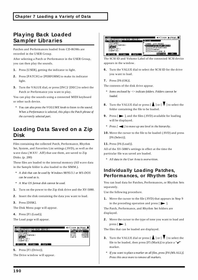
Chapter 7 Loading a Variety of Data
Playing Back Loaded Sampler LibrariesPatches and Performances loaded from CD-ROMs are recorded in the USER Group.
After selecting a Patch or Performance in the USER Group, you can then play the sounds.
1. Press [USER], getting the indicator to light.
2. Press [PATCH] or [PERFORM] to make its indicator light.
3. Turn the VALUE dial, or press [INC]/[DEC] to select the Patch or Performance you want to play.
You can play the sounds using a connected MIDI keyboard or other such device.
* You can also press the VOLUME knob to listen to the sound.
When a Performance is selected, this plays the Patch phrase of
the currently selected part.
Loading Data Saved on a Zip DiskFiles containing the collected Patch, Performance, Rhythm Set, System, and Favorites List settings (.SVD), as well as the wave data (.WAV/.AIF) that use them, are saved to Zip Disks. (p. 200)
These files are loaded to the internal memory (All wave data in the Sample folder is also loaded to the SIMM.).
* A disk that can be used by Windows 98/95/3.1 or MS-DOS
can be used as is.
* A Mac OS format disk cannot be used.
1. Turn on the power to the Zip disk drive and the XV-5080.
2. Insert the disk containing the data you want to load.
3. Press [DISK].
The Disk Menu page will appear.
4. Press [F1 (Load)].
The Load page will appear.fig.07-011.e_70
5. Press [F1 (Drive)].
The Drive window will appear.
fig.07-012.e_70
The SCSI ID and Volume Label of the connected SCSI device appears in the window.
6. Turn the VALUE dial to select the SCSI ID for the drive you want to load.
7. Press [F6 (OK)].
The contents of the disk drive appear.
* Items enclosed by <> indicate folders. Folders cannot be
loaded.
8. Turn the VALUE dial or press [ ] or [ ] to select the folder containing the file to be loaded.
9. Press [ ], and the files (.SVD) available for loading will be displayed.
* Press [ ] to move up one level in the hierarchy.
10. Move the cursor to the file to be loaded (.SVD) and press [F6 (Select)].
11. Press [F6 (Load)].
All of the XV-5080’s settings in effect at the time the particular file was saved are loaded.
* All data in the User Area is overwritten.
Individually Loading Patches, Performances, or Rhythm SetsYou can load data for Patches, Performances, or Rhythm Sets separately.
Use the following procedure.
1. Move the cursor to the file (.SVD) that appears in Step 9
in the preceding operation and press [ ].
The Patch, Performance, and Rhythm Set folders are displayed.
2. Move the cursor to the type of tone you want to load and
press [ ].
The files that can be loaded are displayed.
3. Turn the VALUE dial or press [ ] or [ ] to select the file to be loaded, then press [F5 (Mark)] to place a “✔ ” marker.
* If you want to place a marker on all files, press [F4 (Mk ALL)].
Press this once more to remove all markers.
190
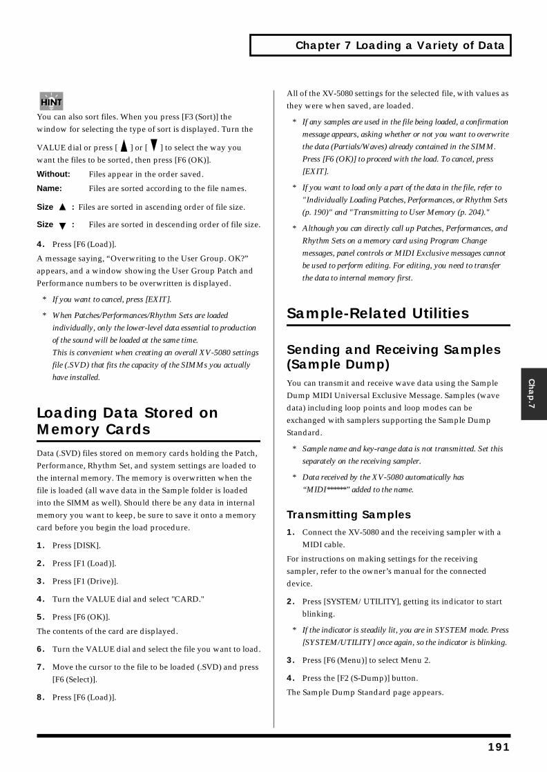
Chapter 7 Loading a Variety of Data
Chap.7
You can also sort files. When you press [F3 (Sort)] the window for selecting the type of sort is displayed. Turn the
VALUE dial or press [ ] or [ ] to select the way you want the files to be sorted, then press [F6 (OK)].
Without: Files appear in the order saved.
Name: Files are sorted according to the file names.
Size : Files are sorted in ascending order of file size.
Size : Files are sorted in descending order of file size.
4. Press [F6 (Load)].
A message saying, “Overwriting to the User Group. OK?” appears, and a window showing the User Group Patch and Performance numbers to be overwritten is displayed.
* If you want to cancel, press [EXIT].
* When Patches/Performances/Rhythm Sets are loaded
individually, only the lower-level data essential to production
of the sound will be loaded at the same time.
This is convenient when creating an overall XV-5080 settings
file (.SVD) that fits the capacity of the SIMMs you actually
have installed.
Loading Data Stored on Memory CardsData (.SVD) files stored on memory cards holding the Patch, Performance, Rhythm Set, and system settings are loaded to the internal memory. The memory is overwritten when the file is loaded (all wave data in the Sample folder is loaded into the SIMM as well). Should there be any data in internal memory you want to keep, be sure to save it onto a memory card before you begin the load procedure.
1. Press [DISK].
2. Press [F1 (Load)].
3. Press [F1 (Drive)].
4. Turn the VALUE dial and select "CARD."
5. Press [F6 (OK)].
The contents of the card are displayed.
6. Turn the VALUE dial and select the file you want to load.
7. Move the cursor to the file to be loaded (.SVD) and press [F6 (Select)].
8. Press [F6 (Load)].
All of the XV-5080 settings for the selected file, with values as they were when saved, are loaded.
* If any samples are used in the file being loaded, a confirmation
message appears, asking whether or not you want to overwrite
the data (Partials/Waves) already contained in the SIMM.
Press [F6 (OK)] to proceed with the load. To cancel, press
[EXIT].
* If you want to load only a part of the data in the file, refer to
"Individually Loading Patches, Performances, or Rhythm Sets
(p. 190)" and "Transmitting to User Memory (p. 204)."
* Although you can directly call up Patches, Performances, and
Rhythm Sets on a memory card using Program Change
messages, panel controls or MIDI Exclusive messages cannot
be used to perform editing. For editing, you need to transfer
the data to internal memory first.
Sample-Related Utilities
Sending and Receiving Samples (Sample Dump)You can transmit and receive wave data using the Sample Dump MIDI Universal Exclusive Message. Samples (wave data) including loop points and loop modes can be exchanged with samplers supporting the Sample Dump Standard.
* Sample name and key-range data is not transmitted. Set this
separately on the receiving sampler.
* Data received by the XV-5080 automatically has
“MIDI******” added to the name.
Transmitting Samples1. Connect the XV-5080 and the receiving sampler with a
MIDI cable.
For instructions on making settings for the receiving sampler, refer to the owner’s manual for the connected device.
2. Press [SYSTEM/UTILITY], getting its indicator to start blinking.
* If the indicator is steadily lit, you are in SYSTEM mode. Press
[SYSTEM/UTILITY] once again, so the indicator is blinking.
3. Press [F6 (Menu)] to select Menu 2.
4. Press the [F2 (S-Dump)] button.
The Sample Dump Standard page appears.
191
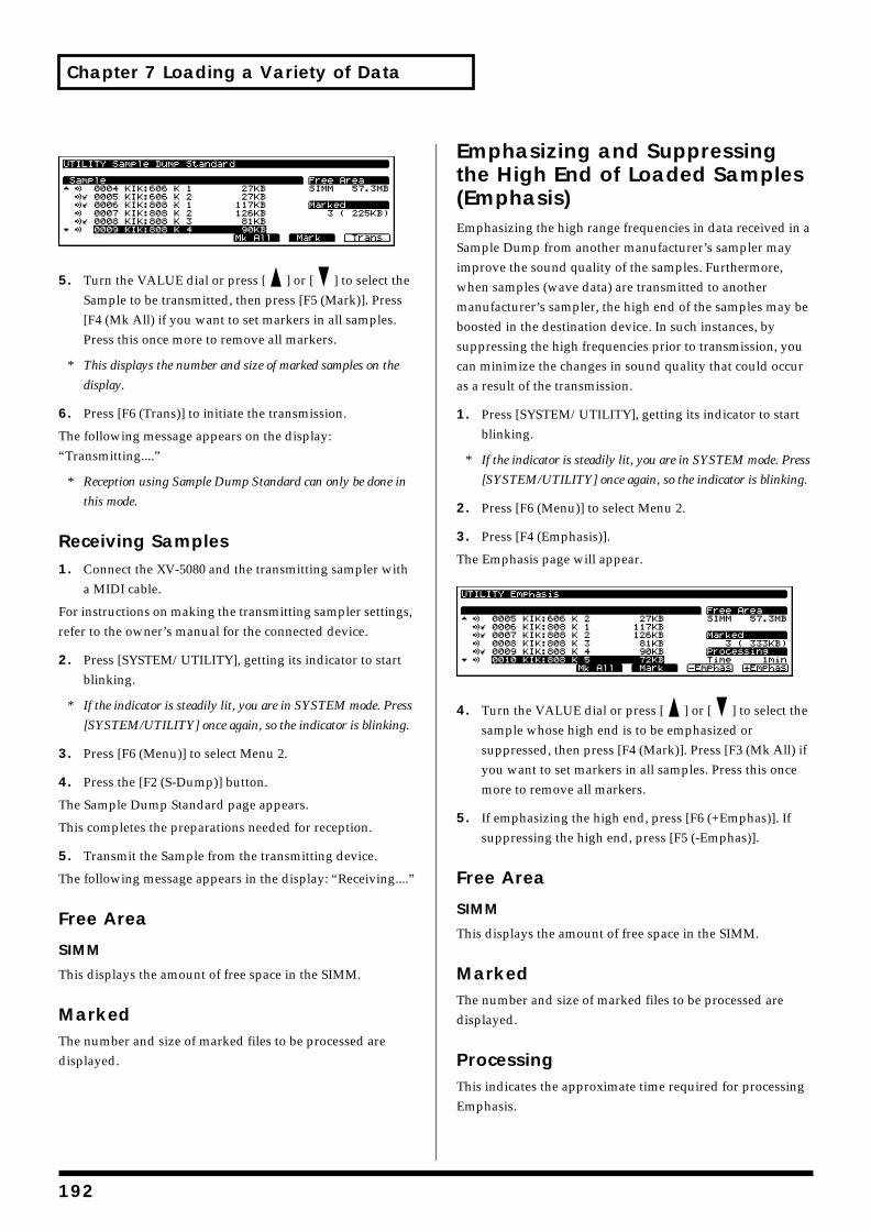
Chapter 7 Loading a Variety of Data
fig.07-04.e_70
f
5. Turn the VALUE dial or press [ ] or [ ] to select the Sample to be transmitted, then press [F5 (Mark)]. Press [F4 (Mk All) if you want to set markers in all samples. Press this once more to remove all markers.
* This displays the number and size of marked samples on the
display.
6. Press [F6 (Trans)] to initiate the transmission.
The following message appears on the display: “Transmitting....”
* Reception using Sample Dump Standard can only be done in
this mode.
Receiving Samples1. Connect the XV-5080 and the transmitting sampler with
a MIDI cable.
For instructions on making the transmitting sampler settings, refer to the owner’s manual for the connected device.
2. Press [SYSTEM/UTILITY], getting its indicator to start blinking.
* If the indicator is steadily lit, you are in SYSTEM mode. Press
[SYSTEM/UTILITY] once again, so the indicator is blinking.
3. Press [F6 (Menu)] to select Menu 2.
4. Press the [F2 (S-Dump)] button.
The Sample Dump Standard page appears.
This completes the preparations needed for reception.
5. Transmit the Sample from the transmitting device.
The following message appears in the display: “Receiving....”
Free Area
SIMM
This displays the amount of free space in the SIMM.
MarkedThe number and size of marked files to be processed are displayed.
Emphasizing and Suppressing the High End of Loaded Samples (Emphasis)Emphasizing the high range frequencies in data received in a Sample Dump from another manufacturer’s sampler may improve the sound quality of the samples. Furthermore, when samples (wave data) are transmitted to another manufacturer’s sampler, the high end of the samples may be boosted in the destination device. In such instances, by suppressing the high frequencies prior to transmission, you can minimize the changes in sound quality that could occur as a result of the transmission.
1. Press [SYSTEM/UTILITY], getting its indicator to start blinking.
* If the indicator is steadily lit, you are in SYSTEM mode. Press
[SYSTEM/UTILITY] once again, so the indicator is blinking.
2. Press [F6 (Menu)] to select Menu 2.
3. Press [F4 (Emphasis)].
The Emphasis page will appear.ig.07-05.e_70
f
4. Turn the VALUE dial or press [ ] or [ ] to select the sample whose high end is to be emphasized or suppressed, then press [F4 (Mark)]. Press [F3 (Mk All) if you want to set markers in all samples. Press this once more to remove all markers.
5. If emphasizing the high end, press [F6 (+Emphas)]. If suppressing the high end, press [F5 (-Emphas)].
Free Area
SIMM
This displays the amount of free space in the SIMM.
MarkedThe number and size of marked files to be processed are displayed.
ProcessingThis indicates the approximate time required for processing Emphasis.
192
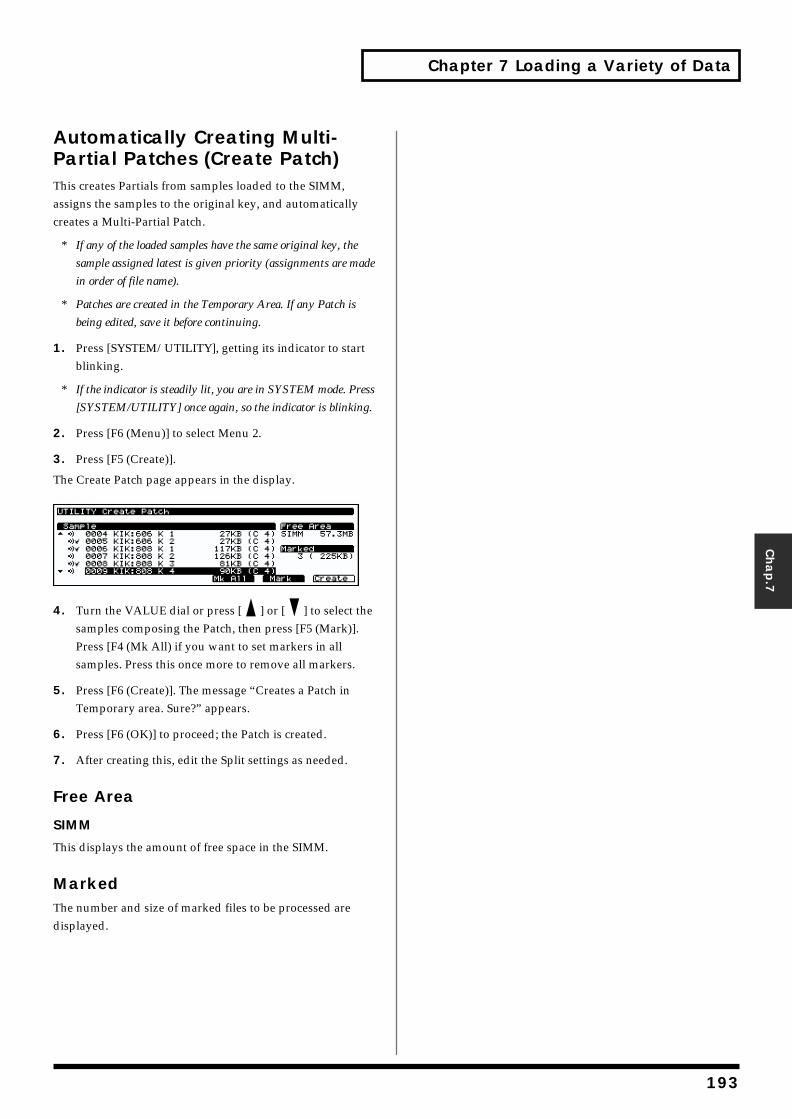
Chapter 7 Loading a Variety of Data
Chap.7
Automatically Creating Multi-Partial Patches (Create Patch)This creates Partials from samples loaded to the SIMM, assigns the samples to the original key, and automatically creates a Multi-Partial Patch.
* If any of the loaded samples have the same original key, the
sample assigned latest is given priority (assignments are made
in order of file name).
* Patches are created in the Temporary Area. If any Patch is
being edited, save it before continuing.
1. Press [SYSTEM/UTILITY], getting its indicator to start blinking.
* If the indicator is steadily lit, you are in SYSTEM mode. Press
[SYSTEM/UTILITY] once again, so the indicator is blinking.
2. Press [F6 (Menu)] to select Menu 2.
3. Press [F5 (Create)].
The Create Patch page appears in the display.ig.07-06.e_70
4. Turn the VALUE dial or press [ ] or [ ] to select the samples composing the Patch, then press [F5 (Mark)]. Press [F4 (Mk All) if you want to set markers in all samples. Press this once more to remove all markers.
5. Press [F6 (Create)]. The message “Creates a Patch in Temporary area. Sure?” appears.
6. Press [F6 (OK)] to proceed; the Patch is created.
7. After creating this, edit the Split settings as needed.
Free Area
SIMM
This displays the amount of free space in the SIMM.
MarkedThe number and size of marked files to be processed are displayed.
193
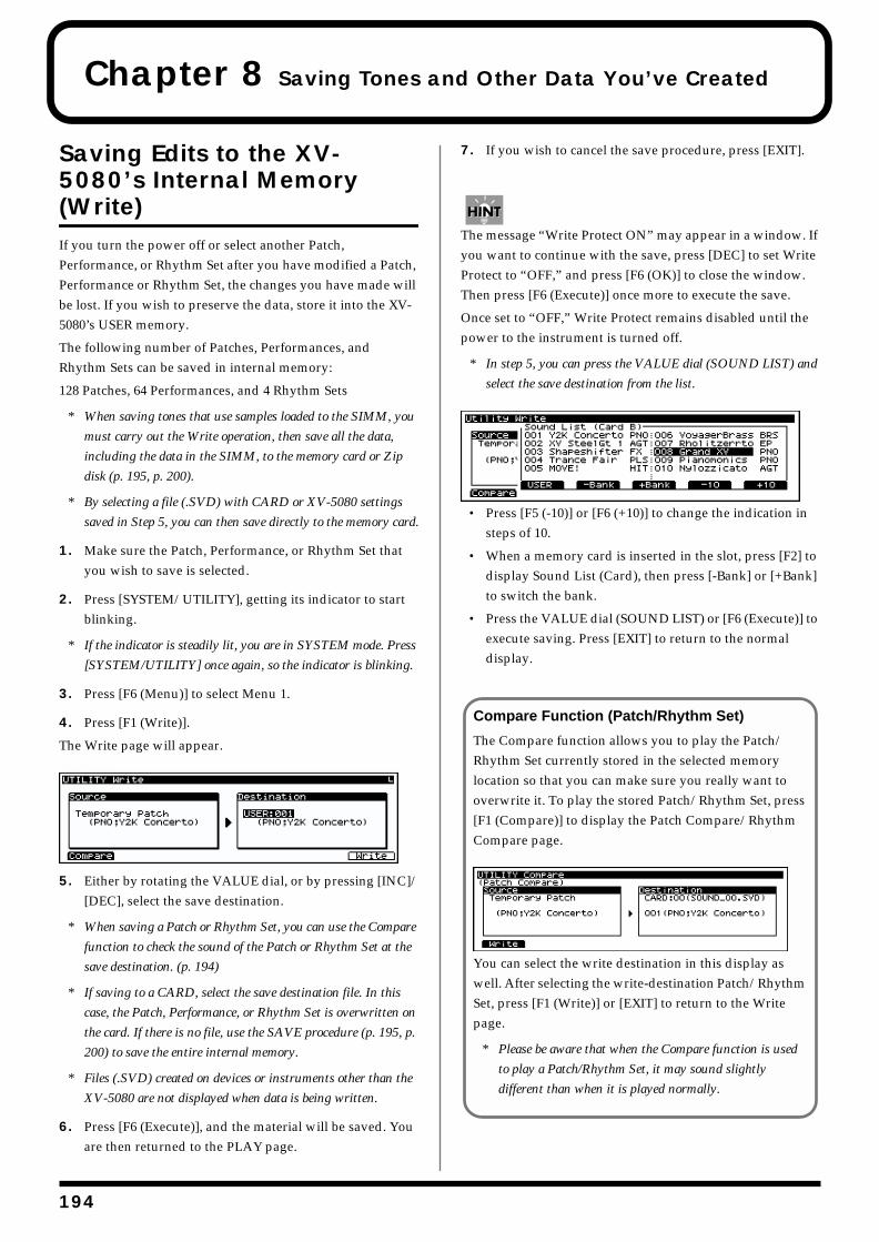
1
Chapter 8 Saving Tones and Other Data You’ve Created
Saving Edits to the XV-5080’s Internal Memory (Write)If you turn the power off or select another Patch, Performance, or Rhythm Set after you have modified a Patch, Performance or Rhythm Set, the changes you have made will be lost. If you wish to preserve the data, store it into the XV-5080’s USER memory.
The following number of Patches, Performances, and Rhythm Sets can be saved in internal memory:
128 Patches, 64 Performances, and 4 Rhythm Sets
* When saving tones that use samples loaded to the SIMM, you
must carry out the Write operation, then save all the data,
including the data in the SIMM, to the memory card or Zip
disk (p. 195, p. 200).
* By selecting a file (.SVD) with CARD or XV-5080 settings
saved in Step 5, you can then save directly to the memory card.
1. Make sure the Patch, Performance, or Rhythm Set that you wish to save is selected.
2. Press [SYSTEM/UTILITY], getting its indicator to start blinking.
* If the indicator is steadily lit, you are in SYSTEM mode. Press
[SYSTEM/UTILITY] once again, so the indicator is blinking.
3. Press [F6 (Menu)] to select Menu 1.
4. Press [F1 (Write)].
The Write page will appear.fig.08-001.e_70
5. Either by rotating the VALUE dial, or by pressing [INC]/[DEC], select the save destination.
* When saving a Patch or Rhythm Set, you can use the Compare
function to check the sound of the Patch or Rhythm Set at the
save destination. (p. 194)
* If saving to a CARD, select the save destination file. In this
case, the Patch, Performance, or Rhythm Set is overwritten on
the card. If there is no file, use the SAVE procedure (p. 195, p.
200) to save the entire internal memory.
* Files (.SVD) created on devices or instruments other than the
XV-5080 are not displayed when data is being written.
6. Press [F6 (Execute)], and the material will be saved. You are then returned to the PLAY page.
7. If you wish to cancel the save procedure, press [EXIT].
The message “Write Protect ON” may appear in a window. If you want to continue with the save, press [DEC] to set Write Protect to “OFF,” and press [F6 (OK)] to close the window. Then press [F6 (Execute)] once more to execute the save.
Once set to “OFF,” Write Protect remains disabled until the power to the instrument is turned off.
* In step 5, you can press the VALUE dial (SOUND LIST) and
select the save destination from the list.fig.08-002.e_70
• Press [F5 (-10)] or [F6 (+10)] to change the indication in steps of 10.
• When a memory card is inserted in the slot, press [F2] to display Sound List (Card), then press [-Bank] or [+Bank] to switch the bank.
• Press the VALUE dial (SOUND LIST) or [F6 (Execute)] to execute saving. Press [EXIT] to return to the normal display.
Compare Function (Patch/Rhythm Set)
The Compare function allows you to play the Patch/Rhythm Set currently stored in the selected memory location so that you can make sure you really want to overwrite it. To play the stored Patch/Rhythm Set, press [F1 (Compare)] to display the Patch Compare/Rhythm Compare page.fig.08-003.e_65
You can select the write destination in this display as well. After selecting the write-destination Patch/Rhythm Set, press [F1 (Write)] or [EXIT] to return to the Write page.
* Please be aware that when the Compare function is used
to play a Patch/Rhythm Set, it may sound slightly
different than when it is played normally.
94
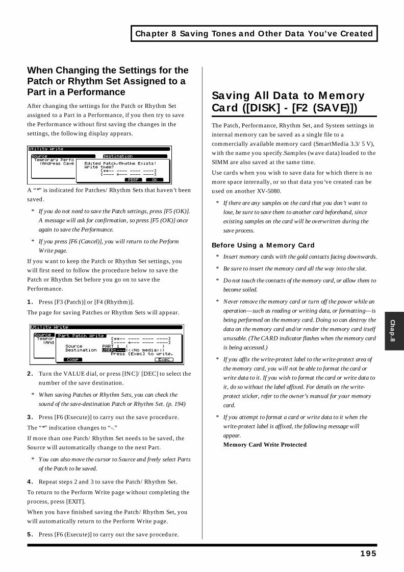
Chapter 8 Saving Tones and Other Data You’ve Created
Chap.8
When Changing the Settings for the Patch or Rhythm Set Assigned to a Part in a PerformanceAfter changing the settings for the Patch or Rhythm Set assigned to a Part in a Performance, if you then try to save the Performance without first saving the changes in the settings, the following display appears.fig.08-004.e_65
A “*” is indicated for Patches/Rhythm Sets that haven’t been saved.
* If you do not need to save the Patch settings, press [F5 (OK)].
A message will ask for confirmation, so press [F5 (OK)] once
again to save the Performance.
* If you press [F6 (Cancel)], you will return to the Perform
Write page.
If you want to keep the Patch or Rhythm Set settings, you will first need to follow the procedure below to save the Patch or Rhythm Set before you go on to save the Performance.
1. Press [F3 (Patch)] or [F4 (Rhythm)].
The page for saving Patches or Rhythm Sets will appear.fig.08-005.e_70
2. Turn the VALUE dial, or press [INC]/[DEC] to select the number of the save destination.
* When saving Patches or Rhythm Sets, you can check the
sound of the save-destination Patch or Rhythm Set. (p. 194)
3. Press [F6 (Execute)] to carry out the save procedure.
The “*” indication changes to “-.”
If more than one Patch/Rhythm Set needs to be saved, the Source will automatically change to the next Part.
* You can also move the cursor to Source and freely select Parts
of the Patch to be saved.
4. Repeat steps 2 and 3 to save the Patch/Rhythm Set.
To return to the Perform Write page without completing the process, press [EXIT].
When you have finished saving the Patch/Rhythm Set, you will automatically return to the Perform Write page.
5. Press [F6 (Execute)] to carry out the save procedure.
Saving All Data to Memory Card ([DISK] - [F2 (SAVE)])The Patch, Performance, Rhythm Set, and System settings in internal memory can be saved as a single file to a commercially available memory card (SmartMedia 3.3/5 V), with the name you specify.Samples (wave data) loaded to the SIMM are also saved at the same time.
Use cards when you wish to save data for which there is no more space internally, or so that data you’ve created can be used on another XV-5080.
* If there are any samples on the card that you don’t want to
lose, be sure to save them to another card beforehand, since
existing samples on the card will be overwritten during the
save process.
Before Using a Memory Card
* Insert memory cards with the gold contacts facing downwards.
* Be sure to insert the memory card all the way into the slot.
* Do not touch the contacts of the memory card, or allow them to
become soiled.
* Never remove the memory card or turn off the power while an
operation—such as reading or writing data, or formatting—is
being performed on the memory card. Doing so can destroy the
data on the memory card and/or render the memory card itself
unusable. (The CARD indicator flashes when the memory card
is being accessed.)
* If you affix the write-protect label to the write-protect area of
the memory card, you will not be able to format the card or
write data to it. If you wish to format the card or write data to
it, do so without the label affixed. For details on the write-
protect sticker, refer to the owner’s manual for your memory
card.
* If you attempt to format a card or write data to it when the
write-protect label is affixed, the following message will
appear. Memory Card Write Protected
195
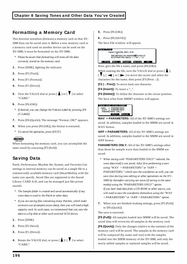
Chapter 8 Saving Tones and Other Data You’ve Created
Formatting a Memory CardThis function initializes (formats) a memory card so that XV-5080 data can be saved onto it. Before a new memory card or a memory card used on another device can be used on the XV-5080, it must be formatted on the XV-5080.
* Please be aware that formatting will erase all the data
currently stored on the memory card.
1. Press [DISK], lighting the indicator.
2. Press [F5 (Tool)].
3. Press [F1 (Format)].
4. Press [F1 (Drive)].
5. Turn the VALUE dial or press [ ] or [ ] to select “CARD.”
6. Press [F6 (OK)].
* If desired, you can change the Volume Label by pressing [F4
(V.Label)].
7. Press [F6 (Quick)]. The message “Format, OK?” appears.
8. When you press [F6 (OK)], the format is executed.
* To cancel the operation, press [EXIT].
When formatting the memory card, you can accomplish the same result by executing [F5 (Full)].
Saving DataPatch, Performance, Rhythm Set, System, and Favorites List settings in internal memory can be saved as a single file to a commercially available memory card (SmartMedia), with the name you specify. Saved files are registered to the Sound Library CARD A-H, and can be managed just like preset sounds.
* The Sample folder is created and saved automatically if any
wave data is used in the Patch or other data.
* If you are saving files containing many Patches, which make
extensive use of samples (wave data), then you will need a high
capacity card. In such cases, we recommend that you save the
data to a Zip disk or other such external SCSI device.
1. Press [DISK].
2. Press [F2 (Save)].
3. Press [F1 (Drive)].
4. Rotate the VALUE dial, or press [ ]/[ ] to select “CARD.”
5. Press [F6 (OK)].
6. Press [F6 (SAVE)].
The Save File window will appear.fig.08-03.e_70
Here, give the file a name, and press [F6 (OK)].
When naming the file, turn the VALUE dial or press [ ], [ ], [ ], or [ ] to move the cursor and select the characters for the name, then press [F3 (Next→)].
[F2 (←Prev)]: To move back one character.
[F4 (Insert)]: To insert a “_”.
[F5 (Delete)]: To delete the character at the cursor position.
The Save what from SIMM? window will appear.
WAV + PARAMETERS: All of the XV-5080’s settings are saved. In addition, samples loaded to the SIMM are saved in WAV format.
AIFF + PARAMETERS: All of the XV-5080’s settings are saved. In addition, samples loaded to the SIMM are saved in AIFF format.
PARAMETERS ONLY: All of the XV-5080’s settings other than those for sample wave data loaded to the SIMM are saved.
* When saving with “PARAMETERS ONLY” selected, the
wave data itself is not saved. After first performing a save
using “WAV + PARAMETERS” or “AIFF +
PARAMETERS,” which save the waveforms as well, you can
save time during tone editing or other operations on the XV-
5080 by thereafter carrying out saves (if saving to the same
media) using the “PARAMETERS ONLY” option.
If you later load data from a CD-ROM or other source, you
will need to save the waveforms themselves using the “WAV
+ PARAMETERS” or “AIFF + PARAMETERS” option.
7. When you are finished making settings, press [F5 (Full)] or [F6 (Quick)].
The save is executed.
[F5 (Full)]: All samples loaded into SIMM will be saved. The saved data will overwrite all samples in the memory card.
[F6 (Quick)]: Only the changes relative to the contents of the memory card will be saved. The samples in the memory card will be compared (by name and size) with the samples loaded into the SIMM memory of the XV-5080, and only the newly added samples or replaced samples will be saved.
196
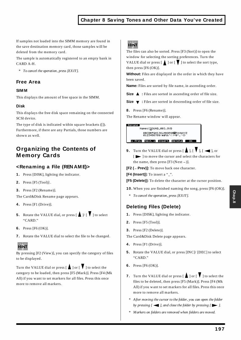
Chapter 8 Saving Tones and Other Data You’ve Created
Chap.8
If samples not loaded into the SIMM memory are found in the save destination memory card, those samples will be deleted from the memory card.
The sample is automatically registered to an empty bank in CARD A-H.
* To cancel the operation, press [EXIT].
Free Area
SIMM
This displays the amount of free space in the SIMM.
Disk
This displays the free disk space remaining on the connected SCSI device.
The type of disk is indicated within square brackets ([]). Furthermore, if there are any Partials, those numbers are shown as well.
Organizing the Contents of Memory Cards
<Renaming a File (RENAME)>1. Press [DISK], lighting the indicator.
2. Press [F5 (Tool)] .
3. Press [F2 (Rename)].
The Card&Disk Rename page appears.
4. Press [F1 (Drive)].
5. Rotate the VALUE dial, or press [ ]/[ ] to select “CARD.”
6. Press [F6 (OK)].
7. Rotate the VALUE dial to select the file to be changed.
By pressing [F2 (View)], you can specify the category of files to be displayed.
Turn the VALUE dial or press [ ] or [ ] to select the category to be loaded, then press [F5 (Mark)]. Press [F4 (Mk All) if you want to set markers for all files. Press this once more to remove all markers.
The files can also be sorted. Press [F3 (Sort)] to open the window for selecting the sorting preferences. Turn the VALUE dial or press [ ] or [ ] to select the sort type, then press [F6 (OK)].
Without: Files are displayed in the order in which they have been saved.
Name: Files are sorted by file name, in ascending order.
Size : Files are sorted in ascending order of file size.
Size : Files are sorted in descending order of file size.
8. Press [F6 (Rename)].
The Rename window will appear.fig.08-04.e_70
9. Turn the VALUE dial or press [ ], [ ], [ ], or
[ ] to move the cursor and select the characters for the name, then press [F3 (Next→)].
[F2 (←Prev)]: To move back one character.
[F4 (Insert)]: To insert a “_”.
[F5 (Delete)]: To delete the character at the cursor position.
10. When you are finished naming the song, press [F6 (OK)].
* To cancel the operation, press [EXIT].
Deleting Files (Delete)1. Press [DISK], lighting the indicator.
2. Press [F5 (Tool)].
3. Press [F2 (Delete)].
The Card&Disk Delete page appears.
4. Press [F1 (Drive)].
5. Rotate the VALUE dial, or press [INC]/[DEC] to select “CARD.”
6. Press [F6 (OK)].
7. Turn the VALUE dial or press [ ] or [ ] to select the files to be deleted, then press [F5 (Mark)]. Press [F4 (Mk All) if you want to set markers for all files. Press this once more to remove all markers.
* After moving the cursor to the folder, you can open the folder
by pressing [ ], and close the folder by pressing [ ].
* Markers on folders are removed when folders are moved.
197
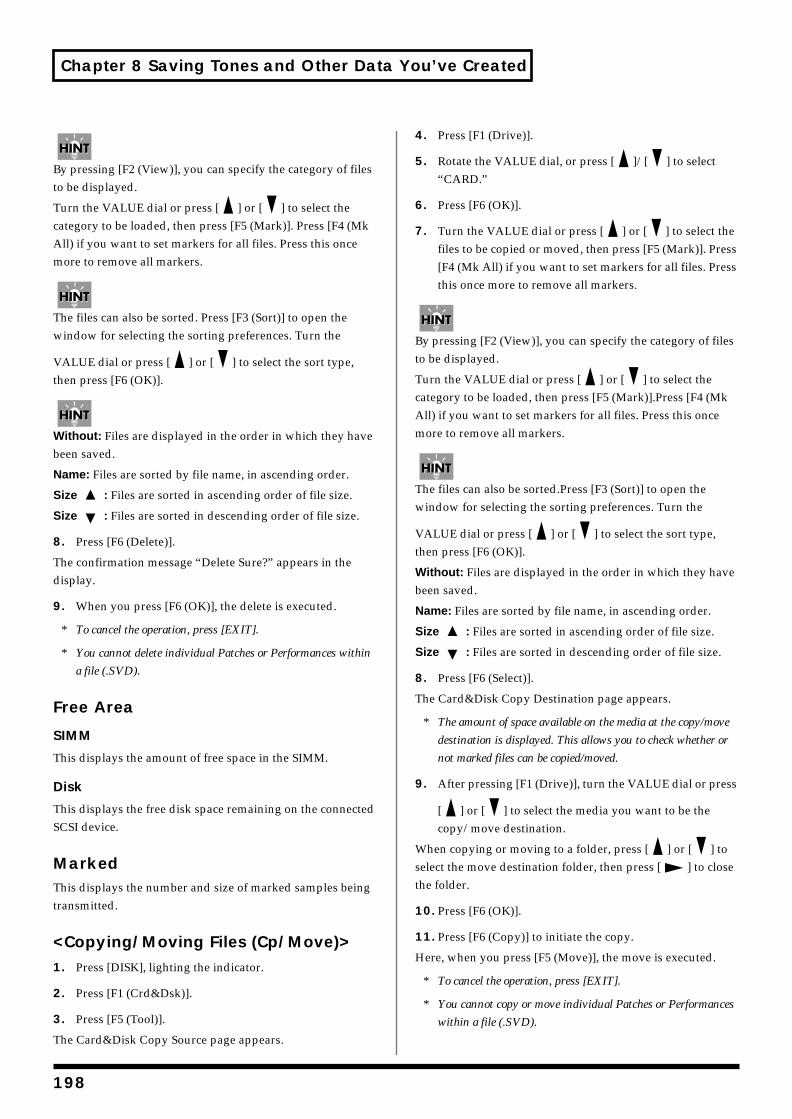
Chapter 8 Saving Tones and Other Data You’ve Created
By pressing [F2 (View)], you can specify the category of files to be displayed.
Turn the VALUE dial or press [ ] or [ ] to select the category to be loaded, then press [F5 (Mark)]. Press [F4 (Mk All) if you want to set markers for all files. Press this once more to remove all markers.
The files can also be sorted. Press [F3 (Sort)] to open the window for selecting the sorting preferences. Turn the
VALUE dial or press [ ] or [ ] to select the sort type, then press [F6 (OK)].
Without: Files are displayed in the order in which they have been saved.
Name: Files are sorted by file name, in ascending order.
Size : Files are sorted in ascending order of file size.
Size : Files are sorted in descending order of file size.
8. Press [F6 (Delete)].
The confirmation message “Delete Sure?” appears in the display.
9. When you press [F6 (OK)], the delete is executed.
* To cancel the operation, press [EXIT].
* You cannot delete individual Patches or Performances within
a file (.SVD).
Free Area
SIMM
This displays the amount of free space in the SIMM.
Disk
This displays the free disk space remaining on the connected SCSI device.
MarkedThis displays the number and size of marked samples being transmitted.
<Copying/Moving Files (Cp/Move)>1. Press [DISK], lighting the indicator.
2. Press [F1 (Crd&Dsk)].
3. Press [F5 (Tool)].
The Card&Disk Copy Source page appears.
4. Press [F1 (Drive)].
5. Rotate the VALUE dial, or press [ ]/[ ] to select “CARD.”
6. Press [F6 (OK)].
7. Turn the VALUE dial or press [ ] or [ ] to select the files to be copied or moved, then press [F5 (Mark)]. Press [F4 (Mk All) if you want to set markers for all files. Press this once more to remove all markers.
By pressing [F2 (View)], you can specify the category of files to be displayed.
Turn the VALUE dial or press [ ] or [ ] to select the category to be loaded, then press [F5 (Mark)].Press [F4 (Mk All) if you want to set markers for all files. Press this once more to remove all markers.
The files can also be sorted.Press [F3 (Sort)] to open the window for selecting the sorting preferences. Turn the
VALUE dial or press [ ] or [ ] to select the sort type, then press [F6 (OK)].
Without: Files are displayed in the order in which they have been saved.
Name: Files are sorted by file name, in ascending order.
Size : Files are sorted in ascending order of file size.
Size : Files are sorted in descending order of file size.
8. Press [F6 (Select)].
The Card&Disk Copy Destination page appears.
* The amount of space available on the media at the copy/move
destination is displayed. This allows you to check whether or
not marked files can be copied/moved.
9. After pressing [F1 (Drive)], turn the VALUE dial or press
[ ] or [ ] to select the media you want to be the copy/move destination.
When copying or moving to a folder, press [ ] or [ ] to select the move destination folder, then press [ ] to close the folder.
10. Press [F6 (OK)].
11. Press [F6 (Copy)] to initiate the copy.
Here, when you press [F5 (Move)], the move is executed.
* To cancel the operation, press [EXIT].
* You cannot copy or move individual Patches or Performances
within a file (.SVD).
198
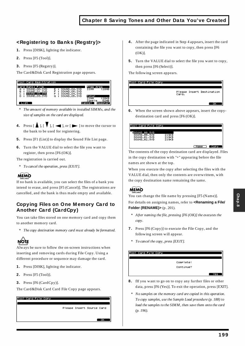
Chapter 8 Saving Tones and Other Data You’ve Created
Chap.8
<Registering to Banks (Regstry)>1. Press [DISK], lighting the indicator.
2. Press [F5 (Tool)].
3. Press [F5 (Regstry)].
The Card&Disk Card Registration page appears.fig.08-05.e_70
* The amount of memory available in installed SIMMs, and the
size of samples on the card are displayed.
4. Press [ ], [ ], [ ], or [ ] to move the cursor to the bank to be used for registering.
5. Press [F1 (List)] to display the Sound File List page.
6. Turn the VALUE dial to select the file you want to register, then press [F6 (OK)].
The registration is carried out.
* To cancel the operation, press [EXIT].
If no bank is available, you can select the files of a bank you intend to erase, and press [F5 (Cancel)]. The registrations are cancelled, and the bank is thus made empty and available.
Copying Files on One Memory Card to Another Card (CardCpy)You can take files stored on one memory card and copy them to another memory card.
* The copy destination memory card must already be formatted.
Always be sure to follow the on-screen instructions when inserting and removing cards during File Copy. Using a different procedure or sequence may damage the card.
1. Press [DISK], lighting the indicator.
2. Press [F5 (Tool)].
3. Press [F6 (CardCpy)].
The Card&Disk Card Card File Copy page appears.fig.08-06.e_70
4. After the page indicated in Step 4 appears, insert the card containing the file you want to copy, then press [F6 (OK)].
5. Turn the VALUE dial to select the file you want to copy, then press [F6 (Select)].
The following screen appears.fig.08-07.e_70
6. When the screen shown above appears, insert the copy-destination card and press [F6 (OK)].
fig.08-08.e_70
The contents of the copy destination card are displayed. Files in the copy destination with "+" appearing before the file names are shown at the top.
When you execute the copy after selecting the files with the VALUE dial, then only the contents are overwrittem, with the copy destination name remaining the same.
You can change the file name by pressing [F5 (Name)].
For details on assigning names, refer to <Renaming a File/
Folder (RENAME)> (p. 201).
* After naming the file, pressing [F6 (OK)] the executes the
copy.
7. Press [F6 (Copy)] to execute the File Copy, and the following screen will appear.
* To cancel the copy, press [EXIT].
09.e_70
8. fIf you want to go on to copy any further files or other data, press [F6 (Yes)]. To exit the operation, press [EXIT].
* No samples on the memory card are copied in this operation.
To copy samples, use the Sample Load procedure (p. 188) to
load the samples to the SIMM, then save them onto the card
(p. 196).
199
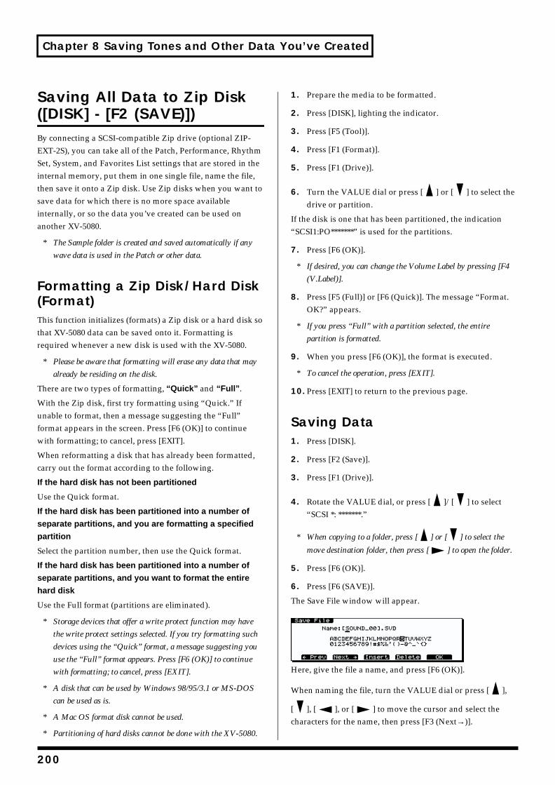
Chapter 8 Saving Tones and Other Data You’ve Created
Saving All Data to Zip Disk ([DISK] - [F2 (SAVE)])By connecting a SCSI-compatible Zip drive (optional ZIP-EXT-2S), you can take all of the Patch, Performance, Rhythm Set, System, and Favorites List settings that are stored in the internal memory, put them in one single file, name the file, then save it onto a Zip disk. Use Zip disks when you want to save data for which there is no more space available internally, or so the data you’ve created can be used on another XV-5080.
* The Sample folder is created and saved automatically if any
wave data is used in the Patch or other data.
Formatting a Zip Disk/Hard Disk (Format)This function initializes (formats) a Zip disk or a hard disk so that XV-5080 data can be saved onto it. Formatting is required whenever a new disk is used with the XV-5080.
* Please be aware that formatting will erase any data that may
already be residing on the disk.
There are two types of formatting, “Quick” and “Full”.
With the Zip disk, first try formatting using “Quick.” If unable to format, then a message suggesting the “Full” format appears in the screen. Press [F6 (OK)] to continue with formatting; to cancel, press [EXIT].
When reformatting a disk that has already been formatted, carry out the format according to the following.
If the hard disk has not been partitioned
Use the Quick format.
If the hard disk has been partitioned into a number of
separate partitions, and you are formatting a specified
partition
Select the partition number, then use the Quick format.
If the hard disk has been partitioned into a number of
separate partitions, and you want to format the entire
hard disk
Use the Full format (partitions are eliminated).
* Storage devices that offer a write protect function may have
the write protect settings selected. If you try formatting such
devices using the “Quick” format, a message suggesting you
use the “Full” format appears. Press [F6 (OK)] to continue
with formatting; to cancel, press [EXIT].
* A disk that can be used by Windows 98/95/3.1 or MS-DOS
can be used as is.
* A Mac OS format disk cannot be used.
* Partitioning of hard disks cannot be done with the XV-5080.
1. Prepare the media to be formatted.
2. Press [DISK], lighting the indicator.
3. Press [F5 (Tool)].
4. Press [F1 (Format)].
5. Press [F1 (Drive)].
6. Turn the VALUE dial or press [ ] or [ ] to select the drive or partition.
If the disk is one that has been partitioned, the indication “SCSI1:PO*******” is used for the partitions.
7. Press [F6 (OK)].
* If desired, you can change the Volume Label by pressing [F4
(V.Label)].
8. Press [F5 (Full)] or [F6 (Quick)]. The message “Format. OK?” appears.
* If you press “Full” with a partition selected, the entire
partition is formatted.
9. When you press [F6 (OK)], the format is executed.
* To cancel the operation, press [EXIT].
10. Press [EXIT] to return to the previous page.
Saving Data1. Press [DISK].
2. Press [F2 (Save)].
3. Press [F1 (Drive)].
4. Rotate the VALUE dial, or press [ ]/[ ] to select “SCSI *: *******.”
* When copying to a folder, press [ ] or [ ] to select the
move destination folder, then press [ ] to open the folder.
5. Press [F6 (OK)].
6. Press [F6 (SAVE)].
The Save File window will appear.fig.08-03.e_70
Here, give the file a name, and press [F6 (OK)].
When naming the file, turn the VALUE dial or press [ ],
[ ], [ ], or [ ] to move the cursor and select the characters for the name, then press [F3 (Next→)].
200
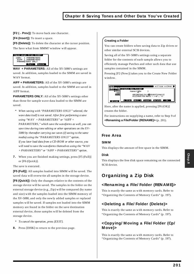
Chapter 8 Saving Tones and Other Data You’ve Created
Chap.8
[F2 (←Prev)]: To move back one character.
[F4 (Insert)]: To insert a space.
[F5 (Delete)]: To delete the character at the cursor position.
The Save what from SIMM? window will appear.
WAV + PARAMETERS: All of the XV-5080’s settings are saved. In addition, samples loaded to the SIMM are saved in WAV format.
AIFF + PARAMETERS: All of the XV-5080’s settings are saved. In addition, samples loaded to the SIMM are saved in AIFF format.
PARAMETERS ONLY: All of the XV-5080’s settings other than those for sample wave data loaded to the SIMM are saved.
* When saving with “PARAMETERS ONLY” selected, the
wave data itself is not saved. After first performing a save
using “WAV + PARAMETERS” or “AIFF +
PARAMETERS,” which save the waveforms as well, you can
save time during tone editing or other operations on the XV-
5080 by thereafter carrying out saves (if saving to the same
media) using the “PARAMETERS ONLY” option.
If you later load data from a CD-ROM or other source, you
will need to save the waveforms themselves using the “WAV
+ PARAMETERS” or “AIFF + PARAMETERS” option.
7. When you are finished making settings, press [F5 (Full)] or [F6 (Quick)].
The save is executed.
[F5 (Full)]: All samples loaded into SIMM will be saved. The saved data will overwrite all samples in the storage device.
[F6 (Quick)]: Only the changes relative to the contents of the storage device will be saved. The samples in the folder on the external storage device (e.g., Zip) will be compared (by name and size) with the samples loaded into the SIMM memory of the XV-5080, and only the newly added samples or replaced samples will be saved. If samples not loaded into the SIMM memory are found in the folder on the save destination external device, those samples will be deleted from the storage device.
* To cancel the operation, press [EXIT].
8. Press [DISK] to return to the previous page.
Free Area
SIMM
This displays the amount of free space in the SIMM.
Disk
This displays the free disk space remaining on the connected SCSI device.
Organizing a Zip Disk
<Renaming a File/Folder (RENAME)>This is exactly the same as with memory cards. Refer to “Organizing the Contents of Memory Cards” (p. 197).
<Deleting a File/Folder (Delete)>This is exactly the same as with memory cards. Refer to “Organizing the Contents of Memory Cards” (p. 197).
<Copying/Moving a File/Folder (Cp/Move)>
This is exactly the same as with memory cards. Refer to “Organizing the Contents of Memory Cards” (p. 197).
Creating a Folder
You can create folders when saving data to Zip drives or other similar external SCSI devices.
Saving all of the XV-5080's settings using a separate folder for the contents of each sample allows you to efficiently manage Patches and other such data that use samples contained in the SIMM.
Pressing [F2 (New)] takes you to the Create New Folder window.fig.08-011.e_70
Here, after the name is applied, pressing [F6 (OK)] creates the folder.
For instructions on supplying a name, refer to Step 9 of <Renaming a File/Folder (RENAME)> (p. 201).
201
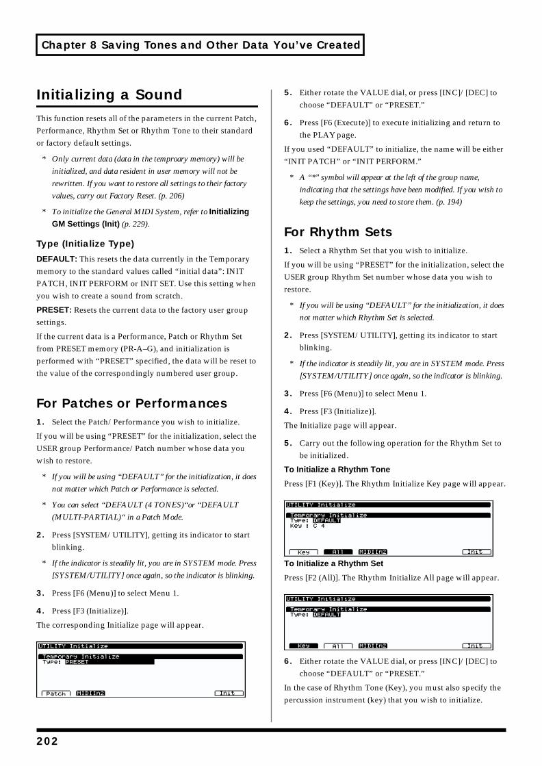
Chapter 8 Saving Tones and Other Data You’ve Created
Initializing a SoundThis function resets all of the parameters in the current Patch, Performance, Rhythm Set or Rhythm Tone to their standard or factory default settings.
* Only current data (data in the temproary memory) will be
initialized, and data resident in user memory will not be
rewritten. If you want to restore all settings to their factory
values, carry out Factory Reset. (p. 206)
* To initialize the General MIDI System, refer to Initializing
GM Settings (Init) (p. 229).
Type (Initialize Type)
DEFAULT: This resets the data currently in the Temporary memory to the standard values called “initial data”: INIT PATCH, INIT PERFORM or INIT SET. Use this setting when you wish to create a sound from scratch.
PRESET: Resets the current data to the factory user group settings.
If the current data is a Performance, Patch or Rhythm Set from PRESET memory (PR-A–G), and initialization is performed with “PRESET” specified, the data will be reset to the value of the correspondingly numbered user group.
For Patches or Performances1. Select the Patch/Performance you wish to initialize.
If you will be using “PRESET” for the initialization, select the USER group Performance/Patch number whose data you wish to restore.
* If you will be using “DEFAULT” for the initialization, it does
not matter which Patch or Performance is selected.
* You can select “DEFAULT (4 TONES)“or “DEFAULT
(MULTI-PARTIAL)“ in a Patch Mode.
2. Press [SYSTEM/UTILITY], getting its indicator to start blinking.
* If the indicator is steadily lit, you are in SYSTEM mode. Press
[SYSTEM/UTILITY] once again, so the indicator is blinking.
3. Press [F6 (Menu)] to select Menu 1.
4. Press [F3 (Initialize)].
The corresponding Initialize page will appear.fig.08-006.e_70
5. Either rotate the VALUE dial, or press [INC]/[DEC] to choose “DEFAULT” or “PRESET.”
6. Press [F6 (Execute)] to execute initializing and return to the PLAY page.
If you used “DEFAULT” to initialize, the name will be either “INIT PATCH” or “INIT PERFORM.”
* A “*” symbol will appear at the left of the group name,
indicating that the settings have been modified. If you wish to
keep the settings, you need to store them. (p. 194)
For Rhythm Sets1. Select a Rhythm Set that you wish to initialize.
If you will be using “PRESET” for the initialization, select the USER group Rhythm Set number whose data you wish to restore.
* If you will be using “DEFAULT” for the initialization, it does
not matter which Rhythm Set is selected.
2. Press [SYSTEM/UTILITY], getting its indicator to start blinking.
* If the indicator is steadily lit, you are in SYSTEM mode. Press
[SYSTEM/UTILITY] once again, so the indicator is blinking.
3. Press [F6 (Menu)] to select Menu 1.
4. Press [F3 (Initialize)].
The Initialize page will appear.
5. Carry out the following operation for the Rhythm Set to be initialized.
To Initialize a Rhythm Tone
Press [F1 (Key)]. The Rhythm Initialize Key page will appear.fig.08-007.e_70
To Initialize a Rhythm Set
Press [F2 (All)]. The Rhythm Initialize All page will appear.fig.08-008.e_70
6. Either rotate the VALUE dial, or press [INC]/[DEC] to choose “DEFAULT” or “PRESET.”
In the case of Rhythm Tone (Key), you must also specify the percussion instrument (key) that you wish to initialize.
202
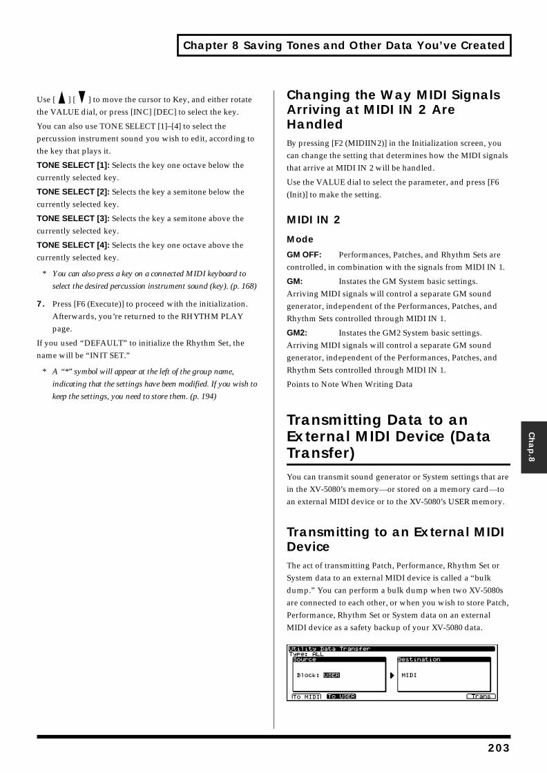
Chapter 8 Saving Tones and Other Data You’ve Created
Chap.8
Use [ ] [ ] to move the cursor to Key, and either rotate the VALUE dial, or press [INC] [DEC] to select the key.
You can also use TONE SELECT [1]–[4] to select the percussion instrument sound you wish to edit, according to the key that plays it.
TONE SELECT [1]: Selects the key one octave below the currently selected key.
TONE SELECT [2]: Selects the key a semitone below the currently selected key.
TONE SELECT [3]: Selects the key a semitone above the currently selected key.
TONE SELECT [4]: Selects the key one octave above the currently selected key.
* You can also press a key on a connected MIDI keyboard to
select the desired percussion instrument sound (key). (p. 168)
7. Press [F6 (Execute)] to proceed with the initialization. Afterwards, you’re returned to the RHYTHM PLAY page.
If you used “DEFAULT” to initialize the Rhythm Set, the name will be “INIT SET.”
* A “*” symbol will appear at the left of the group name,
indicating that the settings have been modified. If you wish to
keep the settings, you need to store them. (p. 194)
Changing the Way MIDI Signals Arriving at MIDI IN 2 Are HandledBy pressing [F2 (MIDIIN2)] in the Initialization screen, you can change the setting that determines how the MIDI signals that arrive at MIDI IN 2 will be handled.
Use the VALUE dial to select the parameter, and press [F6 (Init)] to make the setting.
MIDI IN 2
Mode
GM OFF: Performances, Patches, and Rhythm Sets are controlled, in combination with the signals from MIDI IN 1.
GM: Instates the GM System basic settings. Arriving MIDI signals will control a separate GM sound generator, independent of the Performances, Patches, and Rhythm Sets controlled through MIDI IN 1.
GM2: Instates the GM2 System basic settings. Arriving MIDI signals will control a separate GM sound generator, independent of the Performances, Patches, and Rhythm Sets controlled through MIDI IN 1.
Points to Note When Writing Data
Transmitting Data to an External MIDI Device (Data Transfer)You can transmit sound generator or System settings that are in the XV-5080’s memory—or stored on a memory card—to an external MIDI device or to the XV-5080’s USER memory.
Transmitting to an External MIDI DeviceThe act of transmitting Patch, Performance, Rhythm Set or System data to an external MIDI device is called a “bulk dump.” You can perform a bulk dump when two XV-5080s are connected to each other, or when you wish to store Patch, Performance, Rhythm Set or System data on an external MIDI device as a safety backup of your XV-5080 data.fig.08-009.e_70
203
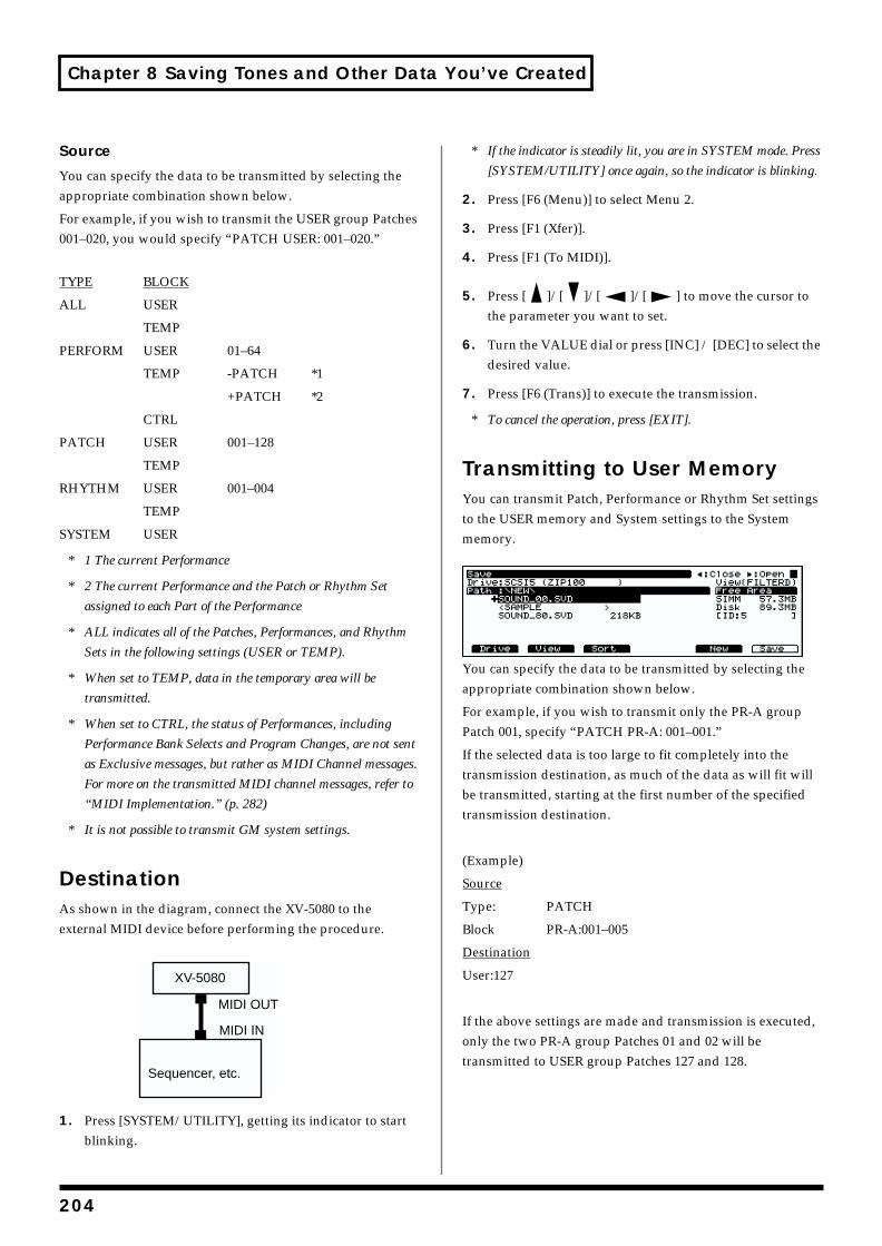
Chapter 8 Saving Tones and Other Data You’ve Created
Source
You can specify the data to be transmitted by selecting the appropriate combination shown below.
For example, if you wish to transmit the USER group Patches 001–020, you would specify “PATCH USER: 001–020.”
TYPE BLOCK
ALL USER
TEMP
PERFORM USER 01–64
TEMP -PATCH *1
+PATCH *2
CTRL
PATCH USER 001–128
TEMP
RHYTHM USER 001–004
TEMP
SYSTEM USER
* 1 The current Performance
* 2 The current Performance and the Patch or Rhythm Set
assigned to each Part of the Performance
* ALL indicates all of the Patches, Performances, and Rhythm
Sets in the following settings (USER or TEMP).
* When set to TEMP, data in the temporary area will be
transmitted.
* When set to CTRL, the status of Performances, including
Performance Bank Selects and Program Changes, are not sent
as Exclusive messages, but rather as MIDI Channel messages.
For more on the transmitted MIDI channel messages, refer to
“MIDI Implementation.” (p. 282)
* It is not possible to transmit GM system settings.
DestinationAs shown in the diagram, connect the XV-5080 to the external MIDI device before performing the procedure.fig.08-012.e_70
1. Press [SYSTEM/UTILITY], getting its indicator to start blinking.
* If the indicator is steadily lit, you are in SYSTEM mode. Press
[SYSTEM/UTILITY] once again, so the indicator is blinking.
2. Press [F6 (Menu)] to select Menu 2.
3. Press [F1 (Xfer)].
4. Press [F1 (To MIDI)].
5. Press [ ]/[ ]/[ ]/[ ] to move the cursor to the parameter you want to set.
6. Turn the VALUE dial or press [INC] / [DEC] to select the desired value.
7. Press [F6 (Trans)] to execute the transmission.
* To cancel the operation, press [EXIT].
Transmitting to User MemoryYou can transmit Patch, Performance or Rhythm Set settings to the USER memory and System settings to the System memory.fig.08-010.e_70
You can specify the data to be transmitted by selecting the appropriate combination shown below.
For example, if you wish to transmit only the PR-A group Patch 001, specify “PATCH PR-A: 001–001.”
If the selected data is too large to fit completely into the transmission destination, as much of the data as will fit will be transmitted, starting at the first number of the specified transmission destination.
(Example)
Source
Type: PATCH
Block PR-A:001–005
Destination
User:127
If the above settings are made and transmission is executed, only the two PR-A group Patches 01 and 02 will be transmitted to USER group Patches 127 and 128.
XV-5080
Sequencer, etc.
MIDI IN
MIDI OUT
204
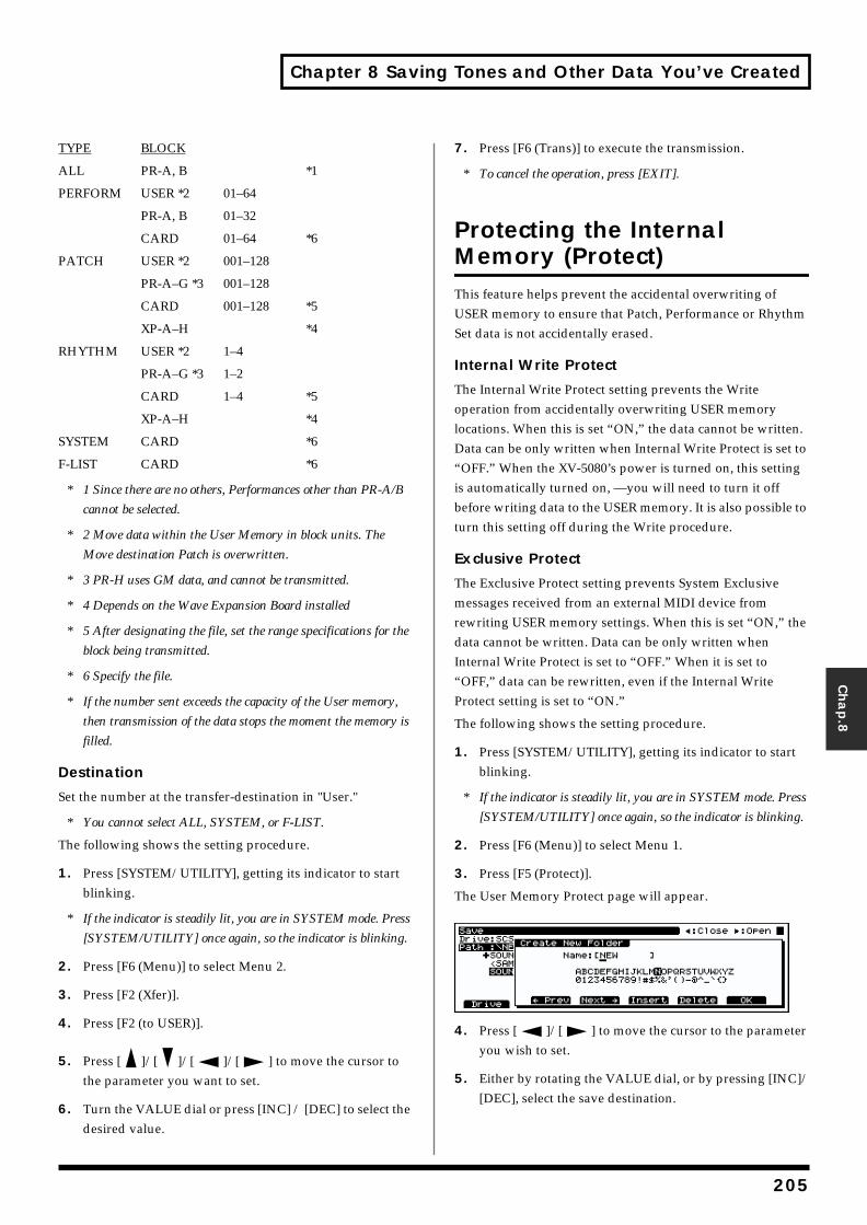
Chapter 8 Saving Tones and Other Data You’ve Created
Chap.8
TYPE BLOCK
ALL PR-A, B *1
PERFORM USER *2 01–64
PR-A, B 01–32
CARD 01–64 *6
PATCH USER *2 001–128
PR-A–G *3 001–128
CARD 001–128 *5
XP-A–H *4
RHYTHM USER *2 1–4
PR-A–G *3 1–2
CARD 1–4 *5
XP-A–H *4
SYSTEM CARD *6
F-LIST CARD *6
* 1 Since there are no others, Performances other than PR-A/B
cannot be selected.
* 2 Move data within the User Memory in block units. The
Move destination Patch is overwritten.
* 3 PR-H uses GM data, and cannot be transmitted.
* 4 Depends on the Wave Expansion Board installed
* 5 After designating the file, set the range specifications for the
block being transmitted.
* 6 Specify the file.
* If the number sent exceeds the capacity of the User memory,
then transmission of the data stops the moment the memory is
filled.
Destination
Set the number at the transfer-destination in "User."
* You cannot select ALL, SYSTEM, or F-LIST.
The following shows the setting procedure.
1. Press [SYSTEM/UTILITY], getting its indicator to start blinking.
* If the indicator is steadily lit, you are in SYSTEM mode. Press
[SYSTEM/UTILITY] once again, so the indicator is blinking.
2. Press [F6 (Menu)] to select Menu 2.
3. Press [F2 (Xfer)].
4. Press [F2 (to USER)].
5. Press [ ]/[ ]/[ ]/[ ] to move the cursor to the parameter you want to set.
6. Turn the VALUE dial or press [INC] / [DEC] to select the desired value.
7. Press [F6 (Trans)] to execute the transmission.
* To cancel the operation, press [EXIT].
Protecting the Internal Memory (Protect)This feature helps prevent the accidental overwriting of USER memory to ensure that Patch, Performance or Rhythm Set data is not accidentally erased.
Internal Write Protect
The Internal Write Protect setting prevents the Write operation from accidentally overwriting USER memory locations. When this is set “ON,” the data cannot be written. Data can be only written when Internal Write Protect is set to “OFF.” When the XV-5080’s power is turned on, this setting is automatically turned on, —you will need to turn it off before writing data to the USER memory. It is also possible to turn this setting off during the Write procedure.
Exclusive Protect
The Exclusive Protect setting prevents System Exclusive messages received from an external MIDI device from rewriting USER memory settings. When this is set “ON,” the data cannot be written. Data can be only written when Internal Write Protect is set to “OFF.” When it is set to “OFF,” data can be rewritten, even if the Internal Write Protect setting is set to “ON.”
The following shows the setting procedure.
1. Press [SYSTEM/UTILITY], getting its indicator to start blinking.
* If the indicator is steadily lit, you are in SYSTEM mode. Press
[SYSTEM/UTILITY] once again, so the indicator is blinking.
2. Press [F6 (Menu)] to select Menu 1.
3. Press [F5 (Protect)].
The User Memory Protect page will appear.fig.08-011.e_70
4. Press [ ]/[ ] to move the cursor to the parameter you wish to set.
5. Either by rotating the VALUE dial, or by pressing [INC]/[DEC], select the save destination.
205
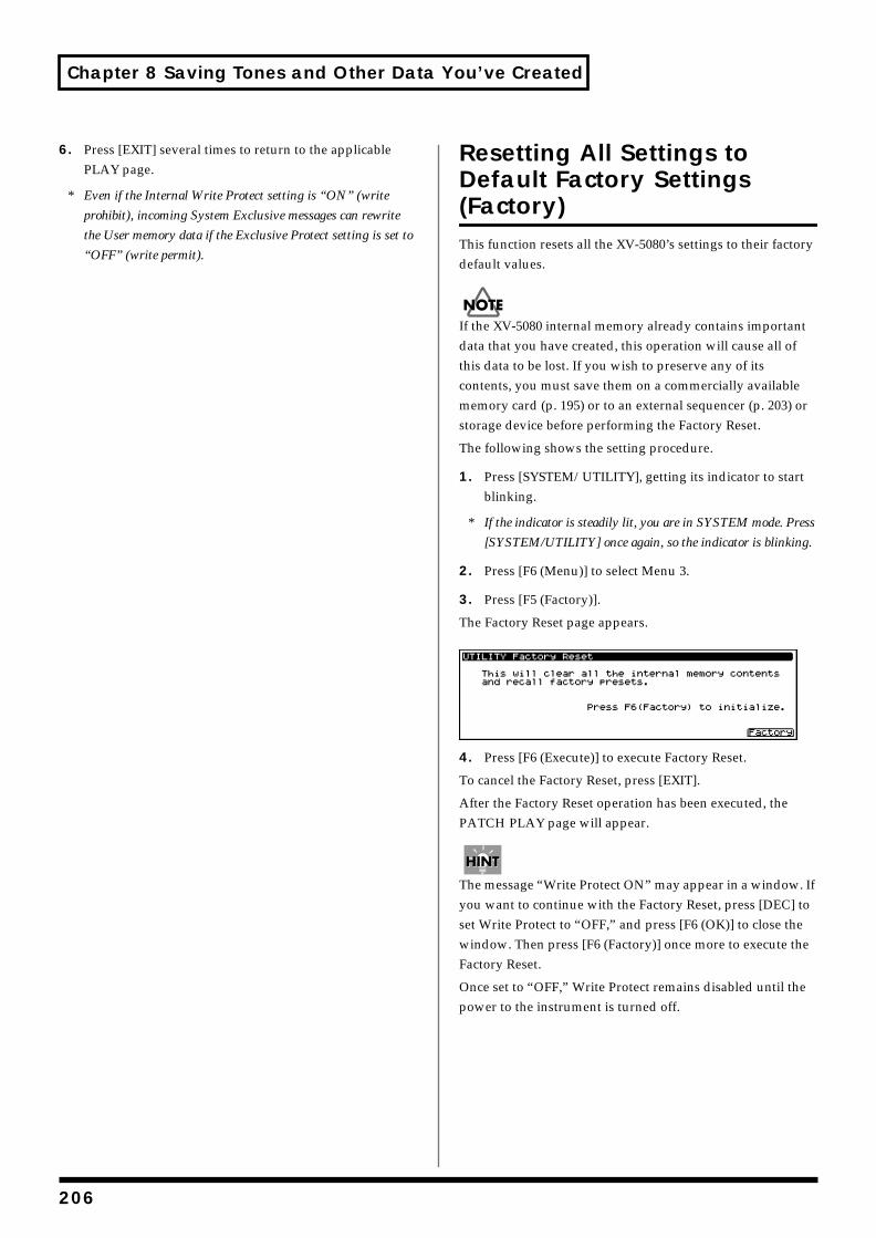
Chapter 8 Saving Tones and Other Data You’ve Created
6. Press [EXIT] several times to return to the applicable PLAY page.
* Even if the Internal Write Protect setting is “ON” (write
prohibit), incoming System Exclusive messages can rewrite
the User memory data if the Exclusive Protect setting is set to
“OFF” (write permit).
Resetting All Settings to Default Factory Settings (Factory)This function resets all the XV-5080’s settings to their factory default values.
If the XV-5080 internal memory already contains important data that you have created, this operation will cause all of this data to be lost. If you wish to preserve any of its contents, you must save them on a commercially available memory card (p. 195) or to an external sequencer (p. 203) or storage device before performing the Factory Reset.
The following shows the setting procedure.
1. Press [SYSTEM/UTILITY], getting its indicator to start blinking.
* If the indicator is steadily lit, you are in SYSTEM mode. Press
[SYSTEM/UTILITY] once again, so the indicator is blinking.
2. Press [F6 (Menu)] to select Menu 3.
3. Press [F5 (Factory)].
The Factory Reset page appears.fig.08-012.e_70
4. Press [F6 (Execute)] to execute Factory Reset.
To cancel the Factory Reset, press [EXIT].
After the Factory Reset operation has been executed, the PATCH PLAY page will appear.
The message “Write Protect ON” may appear in a window. If you want to continue with the Factory Reset, press [DEC] to set Write Protect to “OFF,” and press [F6 (OK)] to close the window. Then press [F6 (Factory)] once more to execute the Factory Reset.
Once set to “OFF,” Write Protect remains disabled until the power to the instrument is turned off.
206
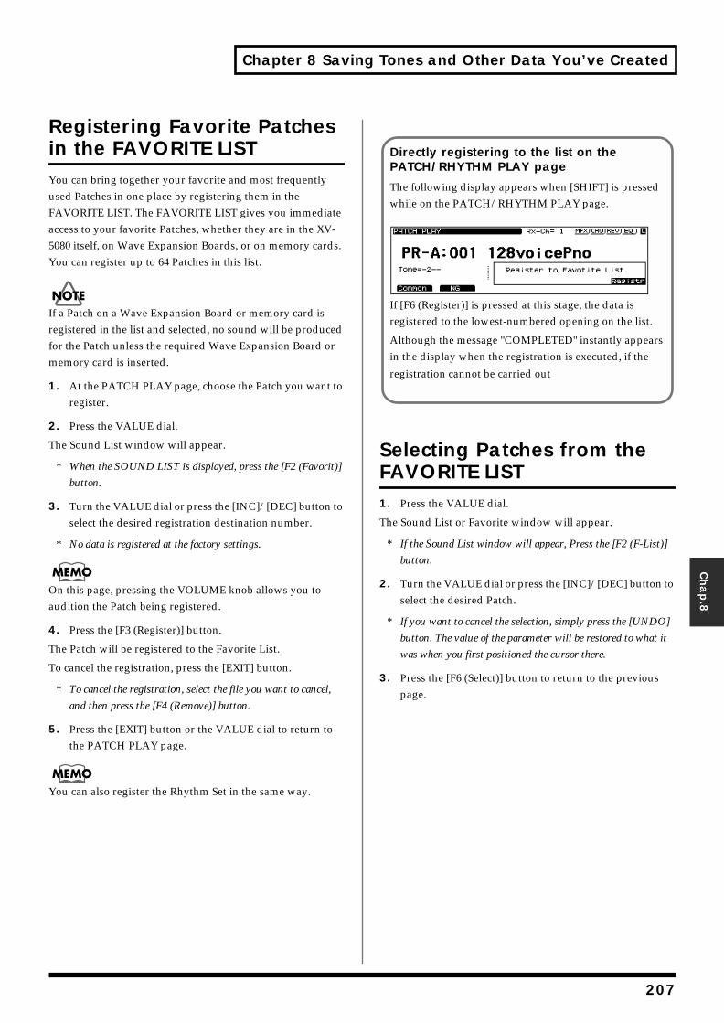
Chapter 8 Saving Tones and Other Data You’ve Created
Chap.8
Registering Favorite Patches in the FAVORITE LISTYou can bring together your favorite and most frequently used Patches in one place by registering them in the FAVORITE LIST. The FAVORITE LIST gives you immediate access to your favorite Patches, whether they are in the XV-5080 itself, on Wave Expansion Boards, or on memory cards. You can register up to 64 Patches in this list.
If a Patch on a Wave Expansion Board or memory card is registered in the list and selected, no sound will be produced for the Patch unless the required Wave Expansion Board or memory card is inserted.
1. At the PATCH PLAY page, choose the Patch you want to register.
2. Press the VALUE dial.
The Sound List window will appear.
* When the SOUND LIST is displayed, press the [F2 (Favorit)]
button.
3. Turn the VALUE dial or press the [INC]/[DEC] button to select the desired registration destination number.
* No data is registered at the factory settings.
On this page, pressing the VOLUME knob allows you to audition the Patch being registered.
4. Press the [F3 (Register)] button.
The Patch will be registered to the Favorite List.
To cancel the registration, press the [EXIT] button.
* To cancel the registration, select the file you want to cancel,
and then press the [F4 (Remove)] button.
5. Press the [EXIT] button or the VALUE dial to return to the PATCH PLAY page.
You can also register the Rhythm Set in the same way.
Selecting Patches from the FAVORITE LIST1. Press the VALUE dial.
The Sound List or Favorite window will appear.
* If the Sound List window will appear, Press the [F2 (F-List)]
button.
2. Turn the VALUE dial or press the [INC]/[DEC] button to select the desired Patch.
* If you want to cancel the selection, simply press the [UNDO]
button. The value of the parameter will be restored to what it
was when you first positioned the cursor there.
3. Press the [F6 (Select)] button to return to the previous page.
Directly registering to the list on the PATCH/RHYTHM PLAY page
The following display appears when [SHIFT] is pressed while on the PATCH/RHYTHM PLAY page.fig.08-13.e_65
If [F6 (Register)] is pressed at this stage, the data is registered to the lowest-numbered opening on the list.
Although the message "COMPLETED" instantly appears in the display when the registration is executed, if the
registration cannot be carried out
207
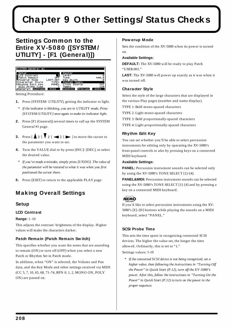
2
Chapter 9 Other Settings/Status Checks
Settings Common to the Entire XV-5080 ([SYSTEM/UTILITY] - [F1 (General)])fig.09-001.e_70
Setting Procedure:
1. Press [SYSTEM/UTILITY], getting the indicator to light.
* If the indicator is blinking, you are in UTILITY mode. Press
[SYSTEM/UTILITY] once again to make its indicator light.
2. Press [F1 (General)] several times to call up the SYSTEM General #1 page.
3. Press [ ]/[ ]/[ ]/[ ] to move the cursor to the parameter you want to set.
4. Turn the VALUE dial or by press [INC]/[DEC], to select the desired value.
* If you’ve made a mistake, simply press [UNDO]. The value of
the parameter will be restored to what it was when you first
positioned the cursor there.
5. Press [EXIT] to return to the applicable PLAY page.
Making Overall Settings
Setup
LCD Contrast
Range: 1–10
This adjusts the contrast/brightness of the display. Higher values will make the characters darker.
Patch Remain (Patch Remain Switch)
This specifies whether you want the notes that are sounding to remain (ON) or turn off (OFF) when you select a new Patch or Rhythm Set in Patch mode.
In addition, when “ON” is selected, the Volume and Pan data, and the Key Mode and other settings received via MIDI (CC 5, 7, 10, 65, 68, 71–74, RPN 0, 1, 2, MONO ON, POLY ON) are passed on.
Powerup Mode
Sets the condition of the XV-5080 when its power is turned on.
Available Settings:
DEFAULT: The XV-5080 will be ready to play Patch “USER:001.”
LAST: The XV-5080 will power up exactly as it was when it was turned off.
Character Style
Select the style of the large characters that are displayed in the various Play pages (number and name display).
TYPE 1: Bold mono-spaced characters
TYPE 2: Light mono-spaced characters
TYPE 3: Bold proportionally-spaced characters
TYPE 4: Light proportionally-spaced characters
Rhythm Edit Key
You can set whether you’ll be able to select percussion instruments for editing only by operating the XV-5080’s front-panel controls or also by pressing keys on a connected MIDI keyboard.
Available Settings:
PANEL: Percussion instrument sounds can be selected only by using the XV-5080’s TONE SELECT [1]–[4].
PANEL&MIDI: Percussion instrument sounds can be selected using the XV-5080’s TONE SELECT [1]–[4] and by pressing a key on a connected MIDI keyboard.
If you’d like to select percussion instruments using the XV-5080’s [E]–[H] buttons while playing the sounds on a MIDI keyboard, select “PANEL.”
SCSI Probe Time
This sets the time spent in recognizing connected SCSI devices. The higher the value set, the longer the time allowed. Ordinarily, this is set to “1.”
Settings values: 1-10
* If the connected SCSI device is not being recognized, set a
higher value, then following the instructions in “Turning Off
the Power” in Quick Start (P.12), turn off the XV-5080’s
power. After this, follow the instructions in “Turning On the
Power” in Quick Start (P.12) to turn on the power in the
proper sequence.
08
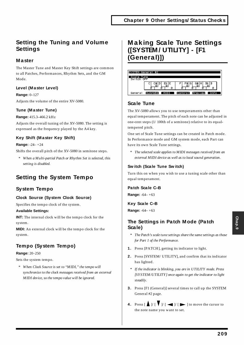
Chapter 9 Other Settings/Status Checks
Setting the TuninSettings
Master
The Master Tune and Masterto all Patches, Performances, Mode.
Level (Master Level)
Range:
0–127
Adjusts the volume of the ent
Tune (Master Tune)
Range:
415.3–466.2 kHz
Adjusts the overall tuning of expressed as the frequency pl
Key Shift (Master Key
Range:
-24– +24
Shifts the overall pitch of the
* When a Multi-partial Patch
setting is disabled.
Setting the Syste
System Tempo
Clock Source (System C
Specifies the tempo clock of t
Available Settings:
INT:
The internal clock will bsystem.
MIDI:
An external clock will bsystem.
Tempo (System Tem
Range:
20–250
Sets the system tempo.
* When Clock Source is set to
synchronize to the clock me
MIDI device, so the tempo v
Chap.9
g and Volume
Key Shift settings are common Rhythm Sets, and the GM
ire XV-5080.
the XV-5080. The setting is ayed by the A4 key.
Shift)
XV-5080 in semitone steps.
or Rhythm Set is selected, this
m Tempo
lock Source)
he system.
e the tempo clock for the
e the tempo clock for the
po)
“MIDI,” the tempo will
ssages received from an external
alue will be ignored.
Making Scale Tune Settings ([SYSTEM/UTILITY] - [F1 (General)])fig.09-002.e_70
Scale TuneThe XV-5080 allows you to use temperaments other than equal temperament. The pitch of each note can be adjusted in one-cent steps (1/100th of a semitone) relative to its equal-tempered pitch.
One set of Scale Tune settings can be created in Patch mode. In Performance mode and GM system mode, each Part can have its own Scale Tune settings.
* The selected scale applies to MIDI messages received from an
external MIDI device as well as to local sound generation.
Switch (Scale Tune Switch)
Turn this on when you wish to use a tuning scale other than equal temperament.
Patch Scale C–B
Range: -64– +63
Key Scale C–B
Range: -64– +63
The Settings in Patch Mode (Patch Scale)
* The Patch’s scale tune settings share the same settings as those
for Part 1 of the Performance.
1. Press [PATCH], getting its indicator to light.
2. Press [SYSTEM/UTILITY], and confirm that its indicator has lighted.
* If the indicator is blinking, you are in UTILITY mode. Press
[SYSTEM/UTILITY] once again to get the indicator to light
steadily.
3. Press [F1 (General)] several times to call up the SYSTEM General #2 page.
4. Press [ ]/[ ]/[ ]/[ ] to move the cursor to the note name you want to set.
209
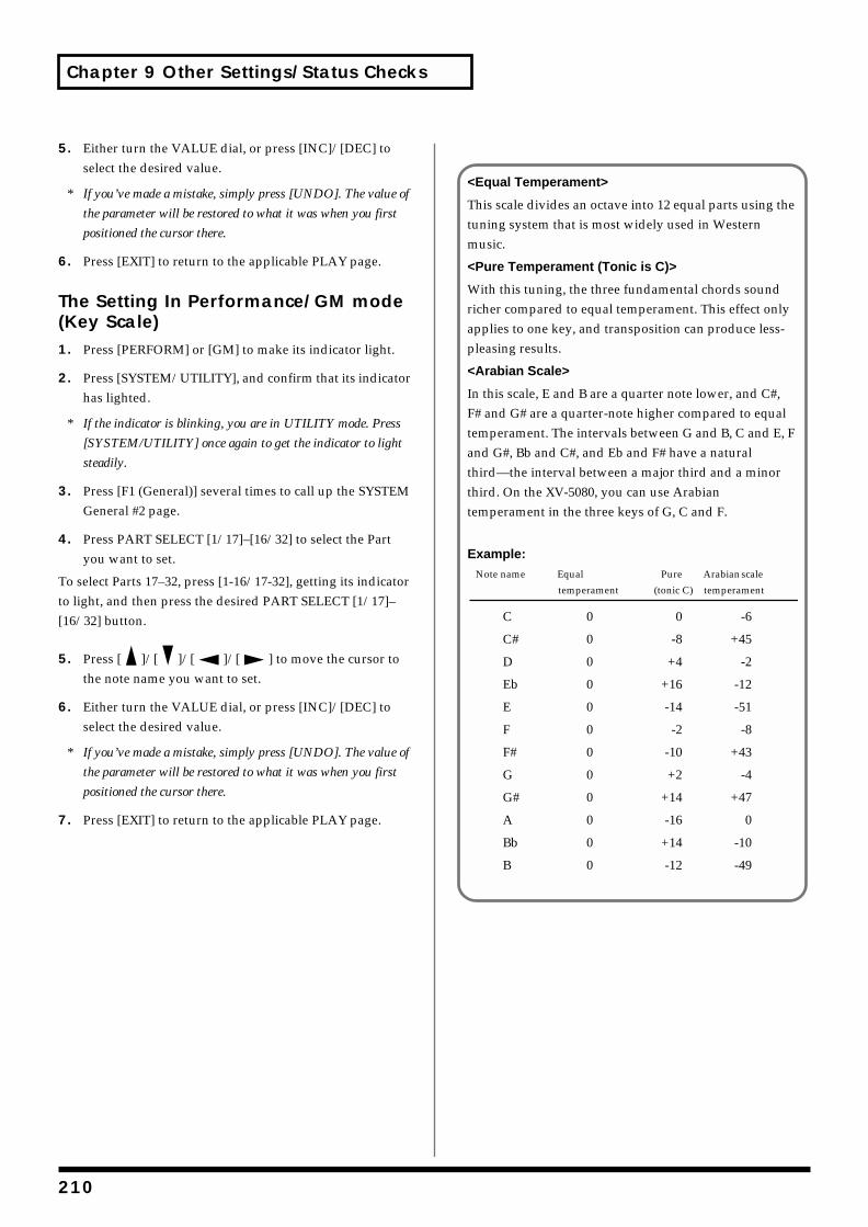
Chapter 9 Other Settings/Status Checks
5. Either turn the VALUE dial, or press [INC]/[DEC] to select the desired value.
* If you’ve made a mistake, simply press [UNDO]. The value of
the parameter will be restored to what it was when you first
positioned the cursor there.
6. Press [EXIT] to return to the applicable PLAY page.
The Setting In Performance/GM mode (Key Scale)1. Press [PERFORM] or [GM] to make its indicator light.
2. Press [SYSTEM/UTILITY], and confirm that its indicator has lighted.
* If the indicator is blinking, you are in UTILITY mode. Press
[SYSTEM/UTILITY] once again to get the indicator to light
steadily.
3. Press [F1 (General)] several times to call up the SYSTEM General #2 page.
4. Press PART SELECT [1/17]–[16/32] to select the Part you want to set.
To select Parts 17–32, press [1-16/17-32], getting its indicator to light, and then press the desired PART SELECT [1/17]–[16/32] button.
5. Press [ ]/[ ]/[ ]/[ ] to move the cursor to the note name you want to set.
6. Either turn the VALUE dial, or press [INC]/[DEC] to select the desired value.
* If you’ve made a mistake, simply press [UNDO]. The value of
the parameter will be restored to what it was when you first
positioned the cursor there.
7. Press [EXIT] to return to the applicable PLAY page.
<Equal Temperament>
This scale divides an octave into 12 equal parts using the tuning system that is most widely used in Western music.
<Pure Temperament (Tonic is C)>
With this tuning, the three fundamental chords sound richer compared to equal temperament. This effect only applies to one key, and transposition can produce less-pleasing results.
<Arabian Scale>
In this scale, E and B are a quarter note lower, and C#, F# and G# are a quarter-note higher compared to equal temperament. The intervals between G and B, C and E, F and G#, Bb and C#, and Eb and F# have a natural third—the interval between a major third and a minor third. On the XV-5080, you can use Arabian temperament in the three keys of G, C and F.
Example:Note name Equal Pure Arabian scale
temperament (tonic C) temperament
C 0 0 -6
C# 0 -8 +45
D 0 +4 -2
Eb 0 +16 -12
E 0 -14 -51
F 0 -2 -8
F# 0 -10 +43
G 0 +2 -4
G# 0 +14 +47
A 0 -16 0
Bb 0 +14 -10
B 0 -12 -49
210
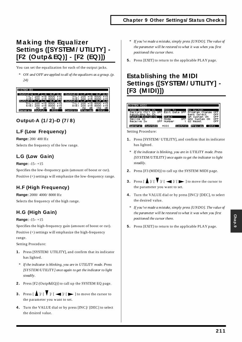
Chapter 9 Other Settings/Status Checks
Chap.9
Making the Equalizer Settings ([SYSTEM/UTILITY] - [F2 (Outp&EQ)] - [F2 (EQ)])You can set the equalization for each of the output jacks.
* ON and OFF are applied to all of the equalizers as a group. (p.
24)fig.09-003.e_70
Output-A (1/2)–D (7/8)
L.F (Low Frequency)Range: 200/400 Hz
Selects the frequency of the low range.
L.G (Low Gain)Range: -15– +15
Specifies the low-frequency gain (amount of boost or cut).
Positive (+) settings will emphasize the low-frequency range.
H.F (High Frequency)Range: 2000/4000/8000 Hz
Selects the frequency of the high range.
H.G (High Gain)Range: -15– +15
Specifies the high-frequency gain (amount of boost or cut).
Positive (+) settings will emphasize the high-frequency range.
Setting Procedure:
1. Press [SYSTEM/UTILITY], and confirm that its indicator has lighted.
* If the indicator is blinking, you are in UTILITY mode. Press
[SYSTEM/UTILITY] once again to get the indicator to light
steadily.
2. Press [F2 (Outp&EQ)] to call up the SYSTEM EQ page.
3. Press [ ]/[ ]/[ ]/[ ] to move the cursor to the parameter you want to set.
4. Turn the VALUE dial or by press [INC]/[DEC] to select the desired value.
* If you’ve made a mistake, simply press [UNDO]. The value of
the parameter will be restored to what it was when you first
positioned the cursor there.
5. Press [EXIT] to return to the applicable PLAY page.
Establishing the MIDI Settings ([SYSTEM/UTILITY] - [F3 (MIDI)])fig.09-004.e_70
Setting Procedure:
1. Press [SYSTEM/UTILITY], and confirm that its indicator has lighted.
* If the indicator is blinking, you are in UTILITY mode. Press
[SYSTEM/UTILITY] once again to get the indicator to light
steadily.
2. Press [F3 (MIDI)] to call up the SYSTEM MIDI page.
3. Press [ ]/[ ]/[ ]/[ ] to move the cursor to the parameter you want to set.
4. Turn the VALUE dial or by press [INC]/[DEC], to select the desired value.
* If you’ve made a mistake, simply press [UNDO]. The value of
the parameter will be restored to what it was when you first
positioned the cursor there.
5. Press [EXIT] to return to the applicable PLAY page.
211
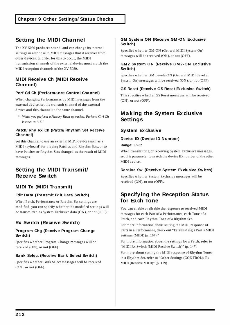
Chapter 9 Other Settings/Status Checks
Setting the MIDI ChannelThe XV-5080 produces sound, and can change its internal settings in response to MIDI messages that it receives from other devices. In order for this to occur, the MIDI transmission channels of the external device must match the MIDI reception channels of the XV-5080.
MIDI Receive Ch (MIDI Receive Channel)
Perf Ctl Ch (Performance Control Channel)
When changing Performances by MIDI messages from the external device, set the transmit channel of the external device and this channel to the same channel.
* When you perform a Factory Reset operation, Perform Ctrl Ch
is reset to “16.”
Patch/Rhy Rx Ch (Patch/Rhythm Set Receive Channel)
Set this channel to use an external MIDI device (such as a MIDI keyboard) for playing Patches and Rhythm Sets, or to have Patches or Rhythm Sets changed as the result of MIDI messages.
Setting the MIDI Transmit/Receive Switch
MIDI Tx (MIDI Transmit)
Edit Data (Transmit Edit Data Switch)
When Patch, Performance or Rhythm Set settings are modified, you can specify whether the modified settings will be transmitted as System Exclusive data (ON), or not (OFF).
Rx Switch (Receive Switch)
Program Chg (Receive Program Change Switch)
Specifies whether Program Change messages will be received (ON), or not (OFF).
Bank Select (Receive Bank Select Switch)
Specifies whether Bank Select messages will be received (ON), or not (OFF).
GM System ON (Receive GM-ON Exclusive Switch)
Specifies whether GM-ON (General MIDI System On) messages will be received (ON), or not (OFF).
GM2 System ON (Receive GM2-ON Exclusive Switch)
Specifies whether GM Level2-ON (General MIDI Level 2 System On) messages will be received (ON), or not (OFF).
GS Reset (Receive GS Reset Exclusive Switch)
This specifies whether GS Reset messages will be received (ON), or not (OFF).
Making the System Exclusive Settings
System Exclusive
Device ID (Device ID Number)
Range: 17–32
When transmitting or receiving System Exclusive messages, set this parameter to match the device ID number of the other MIDI device.
Receive Sw (Receive System Exclusive Switch)
Specifies whether System Exclusive messages will be received (ON), or not (OFF).
Specifying the Reception Status for Each ToneYou can enable or disable the response to received MIDI messages for each Part of a Performance, each Tone of a Patch, and each Rhythm Tone of a Rhythm Set.
For more information about setting the MIDI response of Parts in a Performance, check out “Establishing a Part’s MIDI Settings (MIDI) (p. 164).”
For more information about the settings for a Patch, refer to “MIDI Rx Switch (MIDI Receive Switch)” (p. 147).
For more about setting the MIDI response of Rhythm Tones in a Rhythm Set, refer to “Other Settings (CONTROL)/Rx MIDI (Receive MIDI)” (p. 179).
212
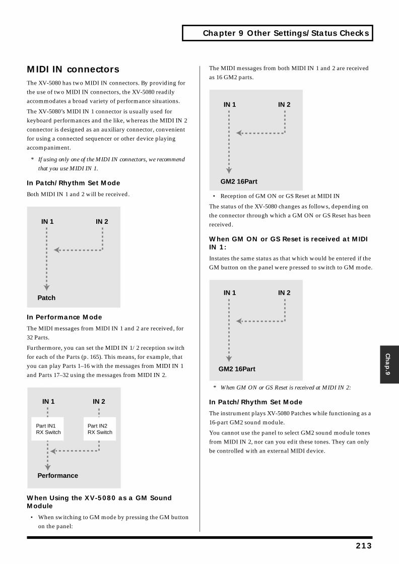
Chapter 9 Other Settings/Status Checks
Chap.9
MIDI IN connectorsThe XV-5080 has two MIDI IN connectors. By providing for the use of two MIDI IN connectors, the XV-5080 readily accommodates a broad variety of performance situations.
The XV-5080’s MIDI IN 1 connector is usually used for keyboard performances and the like, whereas the MIDI IN 2 connector is designed as an auxiliary connector, convenient for using a connected sequencer or other device playing accompaniment.
* If using only one of the MIDI IN connectors, we recommend
that you use MIDI IN 1.
In Patch/Rhythm Set Mode
Both MIDI IN 1 and 2 will be received.fig.09-MIDI IN-1.e
In Performance Mode
The MIDI messages from MIDI IN 1 and 2 are received, for 32 Parts.
Furthermore, you can set the MIDI IN 1/2 reception switch for each of the Parts (p. 165). This means, for example, that you can play Parts 1–16 with the messages from MIDI IN 1 and Parts 17–32 using the messages from MIDI IN 2.fig.09-MIDI IN-2.e
When Using the XV-5080 as a GM Sound Module
• When switching to GM mode by pressing the GM button on the panel:
The MIDI messages from both MIDI IN 1 and 2 are received as 16 GM2 parts.fig.09-MIDI IN-3.e
• Reception of GM ON or GS Reset at MIDI IN
The status of the XV-5080 changes as follows, depending on the connector through which a GM ON or GS Reset has been received.
When GM ON or GS Reset is received at MIDI IN 1:
Instates the same status as that which would be entered if the GM button on the panel were pressed to switch to GM mode.fig.09-MIDI IN-4.e
* When GM ON or GS Reset is received at MIDI IN 2:
In Patch/Rhythm Set Mode
The instrument plays XV-5080 Patches while functioning as a 16-part GM2 sound module.
You cannot use the panel to select GM2 sound module tones from MIDI IN 2, nor can you edit these tones. They can only be controlled with an external MIDI device.
IN 1
Patch
IN 2
IN 1
Performance
IN 2
Part IN2 RX Switch
Part IN1 RX Switch
IN 1 IN 2
GM2 16Part
IN 1 IN 2
GM2 16Part
213
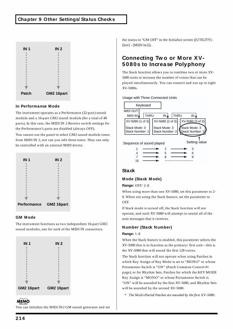
Chapter 9 Other Settings/Status Checks
fig.09-MIDI IN-5.e
In Performance Mode
The instrument operates as a Performance (32-part) sound module and a 16-part GM2 sound module (for a total of 48 parts). In this case, the MIDI IN 2 Receive switch settings for the Performance’s parts are disabled (always OFF).
You cannot use the panel to select GM2 sound module tones from MIDI IN 2, nor can you edit these tones. They can only be controlled with an external MIDI device.fig.09-MIDI IN-6.e
GM Mode
The instrument functions as two independent 16-part GM2 sound modules, one for each of the MIDI IN connectors.fig.09-MIDI IN-7.e
You can initialize the MIDI IN2 GM sound generator and set
the status to "GM OFF" in the Initialize screen ([UTILITY] - [Init] - [MIDI In2]).
Connecting Two or More XV-5080s to Increase PolyphonyThe Stack function allows you to combine two or more XV-5080 units to increase the number of voices that can be played simultaneously. You can connect and use up to eight XV-5080s.fig.09-005.e
Stack
Mode (Stack Mode)
Range: OFF/2–8
When using more than one XV-5080, set this parameter to 2–8. When not using the Stack feature, set the parameter to OFF.
If Stack mode is turned off, the Stack function will not operate, and each XV-5080 will attempt to sound all of the note messages that it receives.
Number (Stack Number)
Range: 1–8
When the Stack feature is enabled, this parameter selects the XV-5080 that is to function as the primary/first unit—this is the XV-5080 that will sound the first 128 voices.
The Stack function will not operate when using Patches in which Key Assign of Key Mode is set to “MONO” or whose Portamento Switch is “ON” (Patch Common Control #1 page), or for Rhythm Sets. Patches for which the KEY MODE Key Assign is “MONO” or whose Portamento Switch is “ON” will be sounded by the first XV-5080, and Rhythm Sets will be sounded by the second XV-5080.
* The Multi-Partial Patches are sounded by the first XV-5080.
IN 1 IN 2
GM2 16partPatch
IN 1 IN 2
GM2 16partPerformance
IN 1 IN 2
GM2 16partGM2 16part
XV-5080 (1 of 3) XV-5080 (2 of 3) XV-5080 (3 of 3)
THRU IN THRU INMIDI IN
MIDI OUT
1 2 34 5 67 8 910
Stack Mode: 3Stack Number: 1
Stack Mode: 3Stack Number: 2
Stack Mode: 3Stack Number: 3
Usage with Three Connected Units
Keyboard
Setting valueSequence of sound played
214
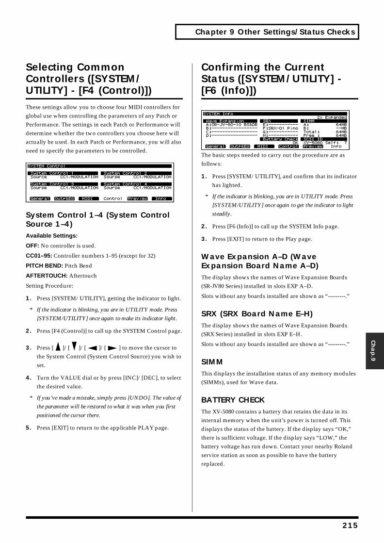
Chapter 9 Other Settings/Status Checks
Chap.9
Selecting Common Controllers ([SYSTEM/UTILITY] - [F4 (Control)])These settings allow you to choose four MIDI controllers for global use when controlling the parameters of any Patch or Performance. The settings in each Patch or Performance will determine whether the two controllers you choose here will actually be used. In each Patch or Performance, you will also need to specify the parameters to be controlled.fig.09-006.e_70
System Control 1–4 (System Control Source 1–4)Available Settings:
OFF: No controller is used.
CC01–95: Controller numbers 1–95 (except for 32)
PITCH BEND: Pitch Bend
AFTERTOUCH: Aftertouch
Setting Procedure:
1. Press [SYSTEM/UTILITY], getting the indicator to light.
* If the indicator is blinking, you are in UTILITY mode. Press
[SYSTEM/UTILITY] once again to make its indicator light.
2. Press [F4 (Control)] to call up the SYSTEM Control page.
3. Press [ ]/[ ]/[ ]/[ ] to move the cursor to the System Control (System Control Source) you wish to set.
4. Turn the VALUE dial or by press [INC]/[DEC], to select the desired value.
* If you’ve made a mistake, simply press [UNDO]. The value of
the parameter will be restored to what it was when you first
positioned the cursor there.
5. Press [EXIT] to return to the applicable PLAY page.
Confirming the Current Status ([SYSTEM/UTILITY] - [F6 (Info)])fig.09-007.e_70
The basic steps needed to carry out the procedure are as follows:
1. Press [SYSTEM/UTILITY], and confirm that its indicator has lighted.
* If the indicator is blinking, you are in UTILITY mode. Press
[SYSTEM/UTILITY] once again to get the indicator to light
steadily.
2. Press [F6 (Info)] to call up the SYSTEM Info page.
3. Press [EXIT] to return to the Play page.
Wave Expansion A–D (Wave Expansion Board Name A–D)The display shows the names of Wave Expansion Boards (SR-JV80 Series) installed in slots EXP A–D.
Slots without any boards installed are shown as “---------.”
SRX (SRX Board Name E–H)The display shows the names of Wave Expansion Boards (SRX Series) installed in slots EXP E–H.
Slots without any boards installed are shown as “---------.”
SIMMThis displays the installation status of any memory modules (SIMMs), used for Wave data.
BATTERY CHECKThe XV-5080 contains a battery that retains the data in its internal memory when the unit’s power is turned off. This displays the status of the battery. If the display says “OK,” there is sufficient voltage. If the display says “LOW,” the battery voltage has run down. Contact your nearby Roland service station as soon as possible to have the battery replaced.
215
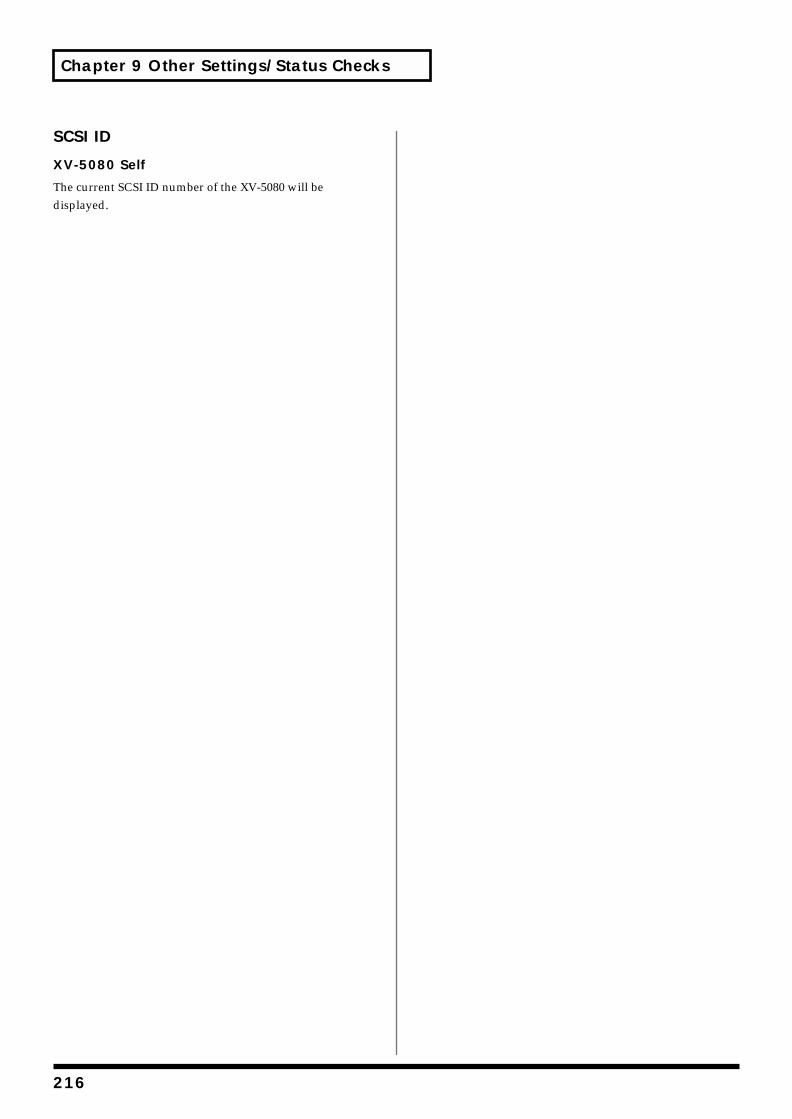
Chapter 9 Other Settings/Status Checks
SCSI ID
XV-5080 Self
The current SCSI ID number of the XV-5080 will be displayed.
216
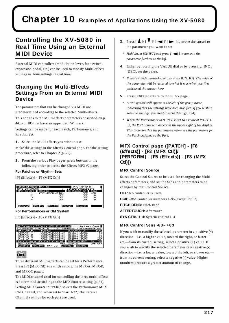
Chapter 10 Examples of Applications Using the XV-5080
Controlling the XV-5080 in Real Time Using an External MIDI DeviceExternal MIDI controllers (modulation lever, foot switch, expression pedal, etc.) can be used to modify Multi-effects settings or Tone settings in real time.
Changing the Multi-Effects Settings From an External MIDI DeviceThe parameters that can be changed via MIDI are predetermined according to the selected Multi-effects.
This applies to the Multi-effects parameters described on p. 44 to p. 105 that have an appended “#” mark.
Settings can be made for each Patch, Performance, and Rhythm Set.
1. Select the Multi-effects you wish to use.
Make the settings in the Effects General page. For the setting procedure, refer to Chapter 2 (p. 25).
2. From the various Play pages, press buttons in the following order to access the Effects MFX #2 page.
For Patches or Rhythm Sets
[F6 (Effects)] - [F3 (MFX Ctl)]fig.10-001.e_70
For Performances or GM System
[F5 (Effects)] - [F3 (MFX Ctl)]fig.10-002.e_70
Three different Multi-effects can be set for a Performance. Press [F3 (MFX Ctl)] to switch among the MFX-A, MFX-B, and MFX-C pages.The MIDI channel used for controlling the three multi-effects is determined according to the MFX Source setting (p. 31). Setting MFX Source to "PERF" selects the Performance MFX Ctrl Channel, and when set to "Part 1-32," the Receive Channel settings for each part are used.
3. Press [ ]/[ ]/[ ]/[ ] to move the cursor to the parameter you want to set.
* Hold down [SHIFT] and press [ ] to move to the
parameter furthest to the left.
4. Either by rotating the VALUE dial or by pressing [INC]/[DEC], set the value.
* If you’ve made a mistake, simply press [UNDO]. The value of
the parameter will be restored to what it was when you first
positioned the cursor there.
5. Press [EXIT] to return to the PLAY page.
* A “*” symbol will appear at the left of the group name,
indicating that the settings have been modified. If you wish to
keep the settings, you need to store them. (p. 194)
* When the Performance SOURCE is set to a value of PART 1–
32, the Part name will appear in the upper right of the display.
This indicates that the parameters below are the parameters for
the Patch assigned to the Part.
MFX Control page ([PATCH] - [F6 (Effects)] - [F3 (MFX Ctl)]/[PERFORM] - [F5 (Effects)] - [F3 (MFX Ctl)])
MFX Control Source
Select the Control Source to be used for changing the Multi-effects parameters, and set the Sens and parameters to be changed by that Control Source.
OFF: No controller is used.
CC01–95: Controller numbers 1–95 (except for 32)
PITCH BEND: Pitch Bend
AFTERTOUCH: Aftertouch
SYS-CTRL 1–4: System control 1–4
MFX Control Sens -63– +63
If you wish to modify the selected parameter in a positive (+) direction—i.e., a higher value, toward the right, or faster etc.—from its current setting, select a positive (+) value. If you wish to modify the selected parameter in a negative (-) direction—i.e., a lower value, toward the left, or slower etc.—from its current setting, select a negative (-) value. Higher numbers produce a greater amount of change.
217
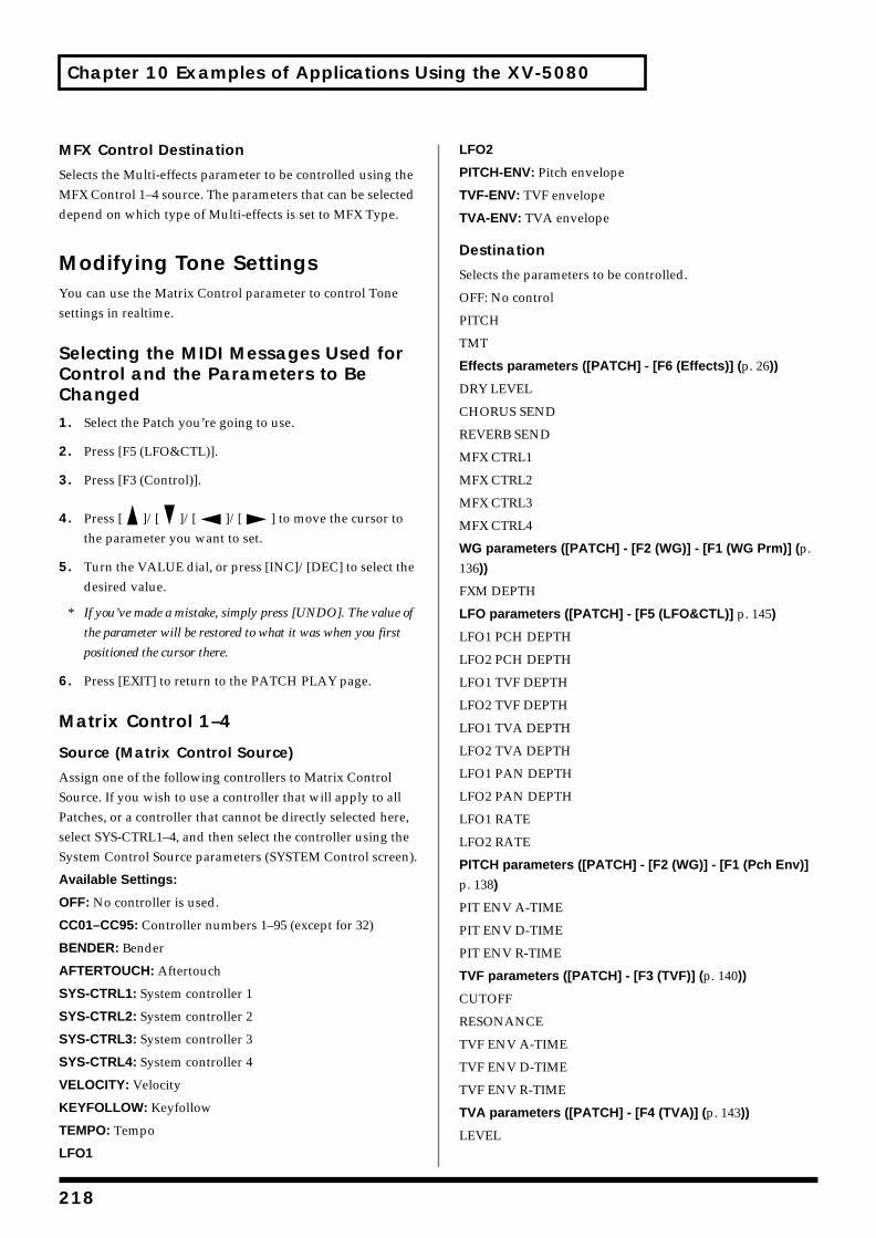
Chapter 10 Examples of Applications Using the XV-5080
MFX Control Destination
Selects the Multi-effects parameter to be controlled using the MFX Control 1–4 source. The parameters that can be selected depend on which type of Multi-effects is set to MFX Type.
Modifying Tone SettingsYou can use the Matrix Control parameter to control Tone settings in realtime.
Selecting the MIDI Messages Used for Control and the Parameters to Be Changed1. Select the Patch you’re going to use.
2. Press [F5 (LFO&CTL)].
3. Press [F3 (Control)].
4. Press [ ]/[ ]/[ ]/[ ] to move the cursor to the parameter you want to set.
5. Turn the VALUE dial, or press [INC]/[DEC] to select the desired value.
* If you’ve made a mistake, simply press [UNDO]. The value of
the parameter will be restored to what it was when you first
positioned the cursor there.
6. Press [EXIT] to return to the PATCH PLAY page.
Matrix Control 1–4
Source (Matrix Control Source)
Assign one of the following controllers to Matrix Control Source. If you wish to use a controller that will apply to all Patches, or a controller that cannot be directly selected here, select SYS-CTRL1–4, and then select the controller using the System Control Source parameters (SYSTEM Control screen).
Available Settings:
OFF: No controller is used.
CC01–CC95: Controller numbers 1–95 (except for 32)
BENDER: Bender
AFTERTOUCH: Aftertouch
SYS-CTRL1: System controller 1
SYS-CTRL2: System controller 2
SYS-CTRL3: System controller 3
SYS-CTRL4: System controller 4
VELOCITY: Velocity
KEYFOLLOW: Keyfollow
TEMPO: Tempo
LFO1
LFO2
PITCH-ENV: Pitch envelope
TVF-ENV: TVF envelope
TVA-ENV: TVA envelope
Destination
Selects the parameters to be controlled.
OFF: No control
PITCH
TMT
Effects parameters ([PATCH] - [F6 (Effects)] (p. 26))
DRY LEVEL
CHORUS SEND
REVERB SEND
MFX CTRL1
MFX CTRL2
MFX CTRL3
MFX CTRL4
WG parameters ([PATCH] - [F2 (WG)] - [F1 (WG Prm)] (p. 136))
FXM DEPTH
LFO parameters ([PATCH] - [F5 (LFO&CTL)] p. 145)
LFO1 PCH DEPTH
LFO2 PCH DEPTH
LFO1 TVF DEPTH
LFO2 TVF DEPTH
LFO1 TVA DEPTH
LFO2 TVA DEPTH
LFO1 PAN DEPTH
LFO2 PAN DEPTH
LFO1 RATE
LFO2 RATE
PITCH parameters ([PATCH] - [F2 (WG)] - [F1 (Pch Env)]
p. 138)
PIT ENV A-TIME
PIT ENV D-TIME
PIT ENV R-TIME
TVF parameters ([PATCH] - [F3 (TVF)] (p. 140))
CUTOFF
RESONANCE
TVF ENV A-TIME
TVF ENV D-TIME
TVF ENV R-TIME
TVA parameters ([PATCH] - [F4 (TVA)] (p. 143))
LEVEL
218
Chapter 10 Examples of Applications Using the XV-5080
Chap.1
0
PAN
TVA ENV A-TIME
TVA ENV D-TIME
TVA ENV R-TIME
Sens
Range: -63– +63
Adjusts the amount of change that will occur in response to controller changes. Negative (-) values invert the change. Negative (-) settings will invert the phase. For LFO rates, negative (-) values slow down the LFO, and positive (+) values will speed it up.
Tone
Selects the Tone to which the two previous parameter settings are applied. “o” turns signifies that the Tone is selected for control, “_” that it is not selected, and “R” that the change being applied is inverted when applied to this Tone.
Applications for Patches
Syncing the LFO Cycle to System Tempo1. Select the Patch you wish to synchronize on the PATCH
PLAY page.
2. Set the Patch Clock Source parameter (PATCH Common General #2 page) to “SYSTEM.”
3. Set the beat length of the Rate (PATCH LFO&TL LFO 1, 2 page) of each Tone to match the System Tempo.
4. Set the System Clock Source parameter (SYSTEM General #1 page) to “INT.”
* When System Clock Source is set to “MIDI,” you can
synchronize the Multi-effect to the tempo of an external MIDI
device.
5. If the System Tempo (SYSTEM General #1 page) changes, the LFO Rate changes along with it.
6. Set the modulation depth as desired using LFO Depth (PATCH LFO&CTL LFO 1, 2 page) for each Tone.
* Tempo synchronization is not available with Multi-Partial
Patches.
Modifying Multi-Effects to Match the System’s TempoYou can modify Multi-effects parameter values in time with the System Tempo when you have selected the following Multi-effects.
MFX Type MFX parameter
16:STEP FLANGER Step Rate
19:TRIPLE TAP DELAY Delay L-R
20:QUADRUPLE TAP DELAY Delay1-4
41:STEREO PHASER Rate,Step Rate
42:KEYSYNC FLANGER Rate,Step Rate
43:FORMANT FILTER Rate
45:MULTI TAP DELAY Delay1-4
46:REVERSE DELAY Delay1-4
47:SHUFFLE DELAY Delay
48:3D DELAY Delay Left/Right/Center
58:SLICER Rate
60:3D CHORUS Rate
61:3D FLANGER Rate,Step Rate
62:TREMOLO Rate
63:AUTO PAN Rate
219
Chapter 10 Examples of Applications Using the XV-5080
64:STEREO PHASER2 Rate,Step Rate
65:STEREO AUTO WAH Rate
66:ST FORMANT FILTER Rate
67:MULTI TAP DELAY 2 Delay1-4
68:REVERSE DELAY 2 Delay1-4
69:SHUFFLE DELAY 2 Delay
70:3D DELAY 2 Delay Left/Right/Center
71:ROTARY 2 Woofer Speed Slow/
Fast,Tweeter Speed Slow/
Fast
72:ROTARY MULTI Rotary High/Low Slow
Rate,Rotary High/Low Fast
Rate
73:KEYBOARD MULTI Phaser Rate,Delay Time
Left/Right
74:RHODES MULTI Phaser Rate,CF Rate,TP Rate
81:GUITAR MULTI A Delay Time Left/Right,CF
Rate
82:GUITAR MULTI B CF Rate
83:GUITAR MULTI C AW Rate,Delay Time Left/
Right,CF Rate
84:CLEAN GUITAR MULTI A Delay Left/Right,CF Rate
85:CLEAN GUITAR MULTI B AW Rate,Delay Left/Right,
CF Rate
86:BASS MULTI CF Rate
89:3D AUTO SPIN Speed
Here is an example in which STEP FLANGER is used for the Multi-effects.
1. Select a Patch on the PATCH PLAY page.
2. Set the Patch Clock Source parameter (PATCH Common General #2 page) to “SYSTEM.”
3. Make sure that MFX Type (PATCH Effects General page) is set to STEP FLANGER.
If not, reset it so that it is.
4. Make sure that Step Rate (PATCH Effects MFX page) is set to a note—not a numerical—value.
If not, reset using a note value.
5. Set the System Clock Source parameter (SYSTEM General #1 page) to “INT.”
* When System Clock Source is set to “MIDI,” you can
synchronize the Multi-effect to the tempo of an external MIDI
device.
6. If the System Tempo (SYSTEM General #1 page) changes, the LFO Rate changes along with it.
Making a Tone’s Delay Time Match the System Tempo
* You can use the Tone Delay only with Four-Tone Patches.
1. Select a Patch on the PATCH PLAY page.
2. Set the Patch Clock Source parameter (PATCH Common General #2 page) to “SYSTEM.”
3. Set the Time parameter (PATCH WG Parameter page) of Tone Delay to the beat length for the tempo you are synchronizing.
If not, reset it so that it is.
4. Set the System Clock Source parameter (SYSTEM General #1 page) to “INT.”
* When System Clock Source is set to “MIDI,” you can
synchronize the Multi-effect to the tempo of an external MIDI
device.
5. If the System Tempo (SYSTEM General #1 page) changes, the LFO Rate changes along with it.
Using a Pedal Switch to Modify the Rotary Speed of the Rotary Effect1. Connect a pedal switch (DP-2, DP-6, etc.) to your
external device (MIDI keyboard, etc.).
2. Set the pedal switch of the external MIDI device to generate FOOT TYPE (CC4) control-change messages.
To learn how to set up the pedal switch, refer to the external MIDI device’s owner’s manual.
3. Select “PR-A: 050 Perky B” on the PATCH PLAY page.
This Patch uses ROTARY as its Multi-effect.
4. Go to the PATCH Effects MFX Control page and set Source of MFX Control 1 to “FOOT TYPE.”
5. Set Destination to “SPEED,” and Sens to “+63.”
When you wish to speed up the rotary effect, press the pedal switch. Release the pedal switch to slow down the rotary effect.
Playing Phrase Loops at a System’s TempoAn optional Wave Expansion Board can contain Patches based on waveforms that are timed—in BPM—phrase loops.
220
Chapter 10 Examples of Applications Using the XV-5080
Chap.1
0
You can play these phrase loops in sync with the System Tempo.
1. On the PATCH PLAY page, select a Patch that uses a phrase loop.
2. Set the Patch Clock Source parameter (PATCH Common General #2 page) to “SYSTEM.”
3. Call up the PATCH WG Parameter page.
4. Press TONE SELECT [1]–[4] to choose the Tone that uses waveforms with BPM indication.
Waveform names that have a BPM number in the first part of the name (such as “132: WAVE NAME”) are phrase loop waveforms.
5. Confirm that Wave Tempo Sync is set to "ON."
6. Set the Time parameter (PATCH WG Parameter page) of Tone Delay to “0.”
If you select a value other than 0, a delay will be applied, and you will not be able to play the Patch normally.
7. Set the System Clock Source parameter (SYSTEM General #1 page) to “INT.”
* When System Clock Source is set to “MIDI,” you can
synchronize the Multi-effect to the tempo of an external MIDI
device.
8. When the System Tempo (SYSTEM General #1 page) changes, the speed of the phrase loop changes along with it.
* The phrase loop will sound at the system’s tempo regardless of
which key you press. The settings for pitch and FXM will be
ignored.
Changing the Part Settings from an External MIDI DeviceBy sending Control Change messages for different Part settings, including volume, panning, and pitch, you can change these settings from an external MIDI device connected to the XV-5080. This lets you control fade-ins and fade-outs, open and close filters, and exercise other controls in real time from the external MIDI device.
The parameters that can be used for changing the settings and the Control Change messages that can be used to change the values are shown below.
For more detailed information about Control Change messages, please refer to “MIDI Implementation” (p. 282).
To changing multi-effects, reverb, or chorus effects from an external MIDI device, send a “System Exclusive message” (p. 285).
Making the Volume Change (p. 282)
• Volume: Controller number 7
Changing the Stereo Location (p. 282)
• Pan: Controller number 10
Applying Portamento (p. 283, p. 288)
• Portament: Controller number 65 (Portamento switch), Controller number 5 (Portamento time)
Changing Sounds’ Attack and Release Time (p. 283)
• Rel: Controller number 72
• Atk: Controller number 73
Changing the Cutoff Frequency (p. 283)
• Cut: Controller number 74
Changing the Resonance (p. 283)
• Res: Controller number 71
Changing the Amount of Internal Chorus/Reverb (p. 284)
• Chorus: Controller number 93
• Reverb: Controller number 91
Changing the Pitch (p. 285)
• Coarse: Controller number 100 (value is 2), Controller number 101 (value is 0), Controller number 6 (value is 16–112)
• Fine: Controller number 100 (value is 1), Controller number 101 (value is 0), Controller number 6 (value is 32–96), Controller number 38 (value is 0–127)
When changing the Coarse parameter, set the amount of change in pitch with the Control Number 6 (Data Entry MSB) value. There is no change in pitch when the value is set to “64.” The pitch is raised as the value increases from 64, and is lowered the more the value decreases below 64.
When changing the Fine parameter, set the amount of change
221
Chapter 10 Examples of Applications Using the XV-5080
in pitch with the Control Number 6 (Data Entry MSB) and Control Number 38 (Data Entry LSB) settings. There is no change in pitch when Data Entry MSB is set to “64” and Data Entry LSB to “0.” The pitch is raised as the respective values increase, and lowered as the respective values decrease.
Specifying the Range of Pitch Bend (p. 284)
• BendRng: Controller number 100 (value is 0), Controller number 101 (value is 0), Controller number 6 (value is 0–12)
<Procedure>
Enable the external MIDI device to send a Control Change message.
For example, if you want to change the volume level, set the external MIDI device to send Control Number 7 (Volume message). In this case, the MIDI channel is matched to the MIDI channel of the Part the volume of which you want to change.
For information on how to make the settings, refer to the owner’s manual for your external MIDI device.
Operate the external MIDI device (adjust the controls, play back using the sequencer, etc.) to send the settings.
Not only is the actual sound played changed, but the values appearing in the display are changed as well.
What is RPN?
“RPN” (Registered Parameter Number) is an extension message prepared by Control Change message. Use RPN when using an external MIDI device to change the XV-5080’s Pitch or Pitch Bend range settings. An RPN has an superior part (RPN MSB) and a subordinate part (RPN LSB). The RPN MSB (Control Number 101) informs the XV-5080 that a setting using RPN is to follow, and the RPN LSB (Control Number 100) value tells the which parameter is to be set. Lastly, the Data Entry (Control Change 6) value sets the degree of change.
Once the XV-5080 has been received an RPN parameter, all further Data Entry messages on that MIDI channel are considered to apply to that parameter. In order to prevent accidents, when the desired setting has been made for the parameter, it is recommended that RPN be set to Null.
For example, to raise the pitch of a certain Part by one half-step (semitone) send the following Control Change message from the external MIDI device.
• Controller number 100: value “2”
• Controller number 101: value “0”
• Controller number 6: value “65”
• Controller number 100: value “127” <- RPN null
• Controller number 101: value “127” <- RPN null
For more detailed information about RPN, please refer to the “MIDI Implementation” (p. 282).
222
Chapter 10 Examples of Applications Using the XV-5080
Chap.1
0
Applications for Matrix Control
Controlling the TMT with the LFO and Changing the Tone’s Cycle Time PlaysWhen TMT (Tone Mix Table) is selected as the Matrix Control destination, you can change the timing at which tones used in Patches are played with the Control Source controller.
Here is an example of a Patch with LFO1 set to Control Source, which changes the timing at which the tone is played based on the LFO1’s amplitude value.
1. Select “PR-E: 043 Morph Pad” on the PATCH PLAY page.
2. In the PATCH Common TMT Vel Range page (p. 133), set the Velocity Range V.L (Lower) and V.U. (Upper) settings for Tone 1 and 2.
Set the Velocity Range for both of the tones as follows.
V.L : V.U
tone = 1 0 : 64
tone = 2 65 : 127
3. In the PATCH Common TMT Vel Range page, set the Velocity Fade L.F and U.F settings to “10” for Tones 1 and 2.
This makes the Tones fade in and out smoothly outside their velocity ranges.
4. Set TMT Control Switch Velocity-Ctrl to “OFF.”
This setting disables the Velocity Range settings made in Step 2 and causes the two Tones to sound simultaneously, regardless of the velocity—the force with which keys are played—received from your MIDI keyboard or sequencer.
5. Set TMT Control Switch Matrix-Ctrl to “ON.”
This setting allows the TMT to be controlled by the Matrix Control Controller. The following chart shows all the relationships between Velocity-Ctrl of TMT Control Switch and Matrix-Ctrl.
(1) (2) (3) (4)
[Velocity-Ctrl] ON OFF ON OFF
[Matrix-Ctrl] OFF OFF ON ON
(1) (3): The Velocity Control settings are enabled, and the two Tones are switched on or off according to the velocity data received from the MIDI keyboard or sequencer.
(2): The Velocity Control settings and TMT control by Matrix
Control are disabled, and the two Tones play simultaneously, regardless of the velocity data received from the MIDI keyboard or sequencer.
(4): TMT Matrix Control is enabled, and the timing of the Tones changes according to the Control Source controller data.
* The Velocity-Ctrl settings are given priority when both
Velocity-Ctrl and Matrix-Ctrl are set to “ON.”
6. Select “LFO1” as the Matrix Control1 source in the PATCH LFO&Ctrl #1 page (p. 146).
7. Set one of Destination:Sns–Tone of Matrix Control1 as shown below.
Destination: TMT
Sns: +63
Tone: o o _ _ (applied to Tone 1 and 2)
8. In the PATCH LFO&Ctrl LFO1 page (p. 145), set the Form (Wave) and Value (Rate) as shown below.
tone=1 tone=2
Form: SIN SIN
Value: 64 127
To change the wave, specify the wave for Tone 1 and 2 in the PATCH WG Parameter page (p. 136).
In this case, you can use the Palette function (p. 135) to display the parameters of four Tones in one screen, making it easier to adjust these settings.
9. Press [EXIT] to return to the PATCH PLAY page.
Other possible applications include synchronizing the Control Source LFO rate to the tempo, assigning Modulation and other parameters to the Control Source, and changing the Tone in realtime from a MIDI keyboard or other such device.
223
Chapter 10 Examples of Applications Using the XV-5080
Using the XV-5080 as a General MIDI Sound ModuleThe XV-5080 features a GM mode (GM2)—a convenient way to play back or create GM score data (music files for General MIDI sound module). You’re able to play back commercial GM score data releases and even modify various parameter settings for enhanced musical expression.
Entering GM ModeBasically GM mode is similar to a special kind of Performance in which a General MIDI System Rhythm Set is assigned to Part 10, and General MIDI System Patches are assigned to other Parts.
But however, you can’t store GM mode settings in user memory.fig.10-003.e_70
The GM PLAY page shows a Patch or Rhythm Set assigned to each Part.
Each time you enter GM mode, the GM Drum Set is assigned to Part 10, and Piano 1 is assigned to other Parts. You can also select other GM Patches and GM Drum Sets for each Part to match the performance.
1. Press [GM] in MODE to call up the GM PLAY page.
When you switch the XV-5080 into GM mode, the sound generator initializes itself for basic GM System settings.
2. To change the current Part, press [ ] or [ ].
3. To change the GM Patch or GM Rhythm Set assigned to the Part, perform the same procedure as you usually do when you select a Patch or Rhythm Set.
Initializing the Sound Generator for General MIDI System Basic SettingsTo play back a GM score correctly, the sound generator must first be initialized to basic GM system settings. The XV-5080’s sound generator is initialized in the General MIDI settings.
• When Switching to GM Mode
• When it receives a GM System On message from an external MIDI device
• When a GM System On message is encountered in the song data being played back
• When the XV-5080’s power is turned on.
• When you execute the GM Initialize function (p. 229).
Playing Back a GM ScoreWhen the XV-5080 is in GM mode, it plays back GM scores correctly. But beyond this, the XV-5080 provides many extended features not defined in GM System specifications, and if you create music files using these extended features, your song may not play back correctly on other GM-compatible sound modules.
In addition, although the XV-5080 can also be compatible with the GS format by receiving a GS Reset MIDI message, Roland’s Sound Canvas Series (including the SC-8850 and SC-8820) features a different sound module system and extended tone map, you may be unable to get MIDI data (GS music data) created especially for use only with the Sound Canvas series of devices to play back properly.
The beginning of a GM score normally contains a GM System On message. So if you play back a GM score starting in the top of a song, XV-5080 will switch itself to GM mode. But if you play back a GM score starting in the middle of a song, XV-5080 may not switch itself to GM mode, and the GM score may not play back correctly. So to be safe, it’s recommended to manually set the XV-5080 to GM mode before playing back a GM score.
Muting a Specific PartWhen you switch over to GM mode, all Parts will be set to receive MIDI messages. To turn off a specific Part so that it will not sound, set the Receive Switch to OFF for the Part.
First, press [RX] to make its indicator light.
At this time, the on/off setting of each Part will be shown by the indicators of PART SELECT [1/17]–[16/32]. Lit is on, and dark is off.
Press PART SELECT [1/17]–[16/32] to turn the Part on/off.
* In GM mode, [1-16/17-32] will be ignored.
224
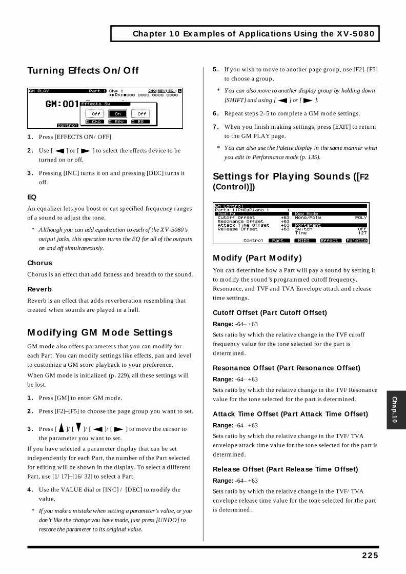
Chapter 10 Examples of Applications Using the XV-5080
Chap.1
0
Turning Effects On/Offfig.10-004.e_70
1. Press [EFFECTS ON/OFF].
2. Use [ ] or [ ] to select the effects device to be turned on or off.
3. Pressing [INC] turns it on and pressing [DEC] turns it off.
EQ
An equalizer lets you boost or cut specified frequency ranges of a sound to adjust the tone.
* Although you can add equalization to each of the XV-5080’s
output jacks, this operation turns the EQ for all of the outputs
on and off simultaneously.
Chorus
Chorus is an effect that add fatness and breadth to the sound.
Reverb
Reverb is an effect that adds reverberation resembling that created when sounds are played in a hall.
Modifying GM Mode SettingsGM mode also offers parameters that you can modify for each Part. You can modify settings like effects, pan and level to customize a GM score playback to your preference.
When GM mode is initialized (p. 229), all these settings will be lost.
1. Press [GM] to enter GM mode.
2. Press [F2]–[F5] to choose the page group you want to set.
3. Press [ ]/[ ]/[ ]/[ ] to move the cursor to the parameter you want to set.
If you have selected a parameter display that can be set independently for each Part, the number of the Part selected for editing will be shown in the display. To select a different Part, use [1/17]–[16/32] to select a Part.
4. Use the VALUE dial or [INC] / [DEC] to modify the value.
* If you make a mistake when setting a parameter’s value, or you
don’t like the change you have made, just press [UNDO] to
restore the parameter to its original value.
5. If you wish to move to another page group, use [F2]–[F5] to choose a group.
* You can also move to another display group by holding down
[SHIFT] and using [ ] or [ ].
6. Repeat steps 2–5 to complete a GM mode settings.
7. When you finish making settings, press [EXIT] to return to the GM PLAY page.
* You can also use the Palette display in the same manner when
you edit in Performance mode (p. 135).
Settings for Playing Sounds ([F2 (Control)])fig.10-005.e_70
Modify (Part Modify)You can determine how a Part will pay a sound by setting it to modify the sound’s programmed cutoff frequency, Resonance, and TVF and TVA Envelope attack and release time settings.
Cutoff Offset (Part Cutoff Offset)
Range: -64– +63
Sets ratio by which the relative change in the TVF cutoff frequency value for the tone selected for the part is determined.
Resonance Offset (Part Resonance Offset)
Range: -64– +63
Sets ratio by which the relative change in the TVF Resonance value for the tone selected for the part is determined.
Attack Time Offset (Part Attack Time Offset)
Range: -64– +63
Sets ratio by which the relative change in the TVF/TVA envelope attack time value for the tone selected for the part is determined.
Release Offset (Part Release Time Offset)
Range: -64– +63
Sets ratio by which the relative change in the TVF/TVA envelope release time value for the tone selected for the part is determined.
225
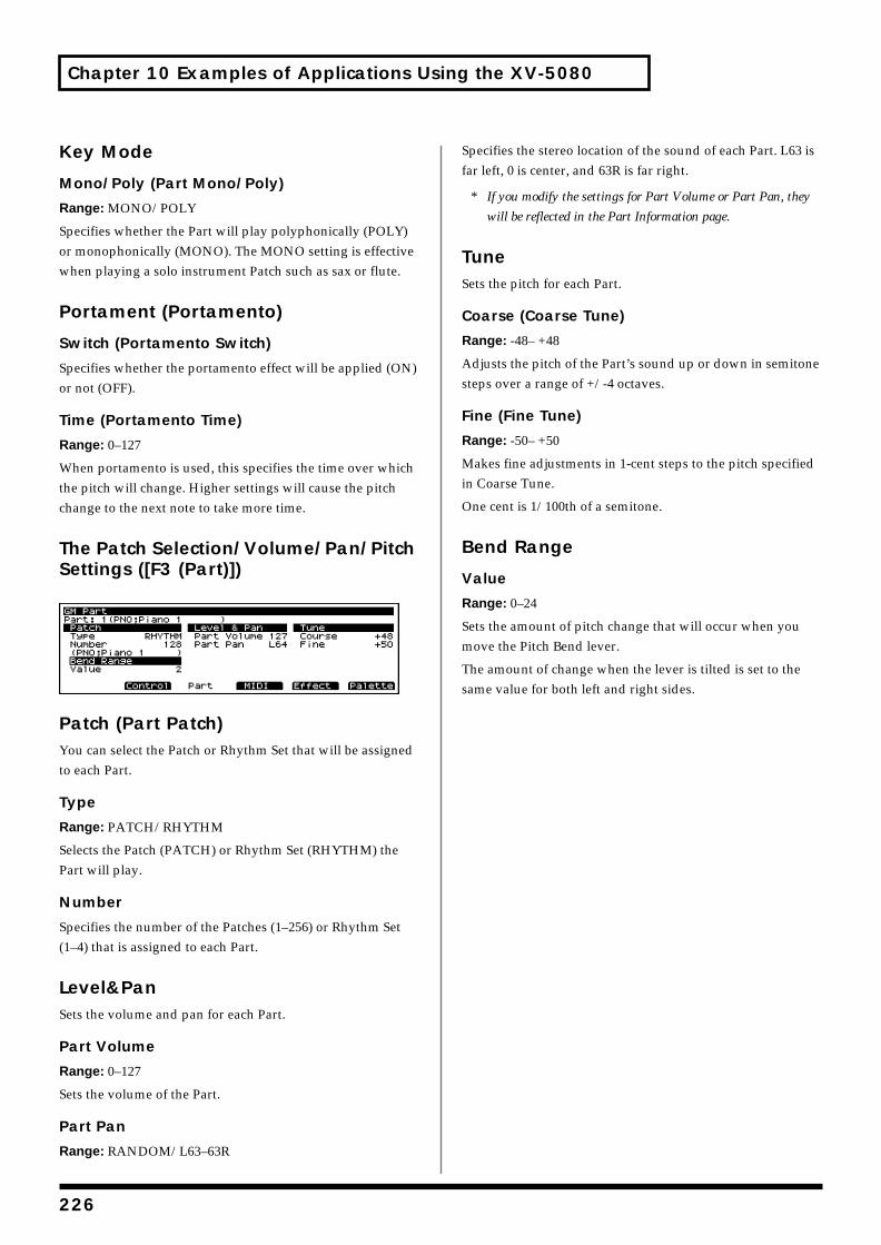
Chapter 10 Examples of Applications Using the XV-5080
Key Mode
Mono/Poly (Part Mono/Poly)
Range: MONO/POLY
Specifies whether the Part will play polyphonically (POLY) or monophonically (MONO). The MONO setting is effective when playing a solo instrument Patch such as sax or flute.
Portament (Portamento)
Switch (Portamento Switch)
Specifies whether the portamento effect will be applied (ON) or not (OFF).
Time (Portamento Time)
Range: 0–127
When portamento is used, this specifies the time over which the pitch will change. Higher settings will cause the pitch change to the next note to take more time.
The Patch Selection/Volume/Pan/Pitch Settings ([F3 (Part)])fig.10-006.e_70
Patch (Part Patch)You can select the Patch or Rhythm Set that will be assigned to each Part.
Type
Range: PATCH/RHYTHM
Selects the Patch (PATCH) or Rhythm Set (RHYTHM) the Part will play.
Number
Specifies the number of the Patches (1–256) or Rhythm Set (1–4) that is assigned to each Part.
Level&PanSets the volume and pan for each Part.
Part Volume
Range: 0–127
Sets the volume of the Part.
Part Pan
Range: RANDOM/L63–63R
Specifies the stereo location of the sound of each Part. L63 is far left, 0 is center, and 63R is far right.
* If you modify the settings for Part Volume or Part Pan, they
will be reflected in the Part Information page.
TuneSets the pitch for each Part.
Coarse (Coarse Tune)
Range: -48– +48
Adjusts the pitch of the Part’s sound up or down in semitone steps over a range of +/-4 octaves.
Fine (Fine Tune)
Range: -50– +50
Makes fine adjustments in 1-cent steps to the pitch specified in Coarse Tune.
One cent is 1/100th of a semitone.
Bend Range
Value
Range: 0–24
Sets the amount of pitch change that will occur when you move the Pitch Bend lever.
The amount of change when the lever is tilted is set to the same value for both left and right sides.
226
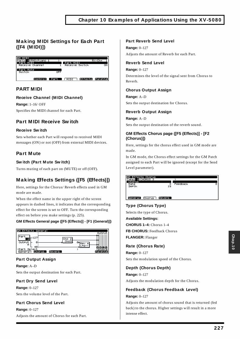
Chapter 10 Examples of Applications Using the XV-5080
Chap.1
0
Making MIDI Settings for Each Part ([F4 (MIDI)])fig.10-007.e_70
PART MIDI
Receive Channel (MIDI Channel)
Range: 1–16/OFF
Specifies the MIDI channel for each Part.
Part MIDI Receive Switch
Receive Switch
Sets whether each Part will respond to received MIDI messages (ON) or not (OFF) from external MIDI devices.
Part Mute
Switch (Part Mute Switch)
Turns muting of each part on (MUTE) or off (OFF).
Making Effects Settings ([F5 (Effects)])Here, settings for the Chorus/Reverb effects used in GM mode are made.
When the effect name in the upper right of the screen appears in dashed lines, it indicates that the corresponding effect for the screen is set to OFF. Turn the corresponding effect on before you make settings (p. 225).
GM Effects General page ([F5 (Effects)] - [F1 (General)])fig.10-008.e_70
Part Output Assign
Range: A–D
Sets the output destination for each Part.
Part Dry Send Level
Range: 0–127
Sets the volume level of the Part.
Part Chorus Send Level
Range: 0–127
Adjusts the amount of Chorus for each Part.
Part Reverb Send Level
Range: 0–127
Adjusts the amount of Reverb for each Part.
Reverb Send Level
Range: 0–127
Determines the level of the signal sent from Chorus to Reverb.
Chorus Output Assign
Range: A–D
Sets the output destination for Chorus.
Reverb Output Assign
Range: A–D
Sets the output destination of the reverb sound.
GM Effects Chorus page ([F5 (Effects)] - [F2 (Chorus)])
Here, settings for the chorus effect used in GM mode are made.
In GM mode, the Chorus effect settings for the GM Patch assigned to each Part will be ignored (except for the Send Level parameter).fig.10-009.e_70
Type (Chorus Type)
Selects the type of Chorus.
Available Settings:
CHORUS 1–4: Chorus 1–4
FB CHORUS: Feedback Chorus
FLANGER: Flanger
Rate (Chorus Rate)
Range: 0–127
Sets the modulation speed of the Chorus.
Depth (Chorus Depth)
Range: 0–127
Adjusts the modulation depth for the Chorus.
Feedback (Chorus Feedback Level)
Range: 0–127
Adjusts the amount of chorus sound that is returned (fed back) to the chorus. Higher settings will result in a more intense effect.
227
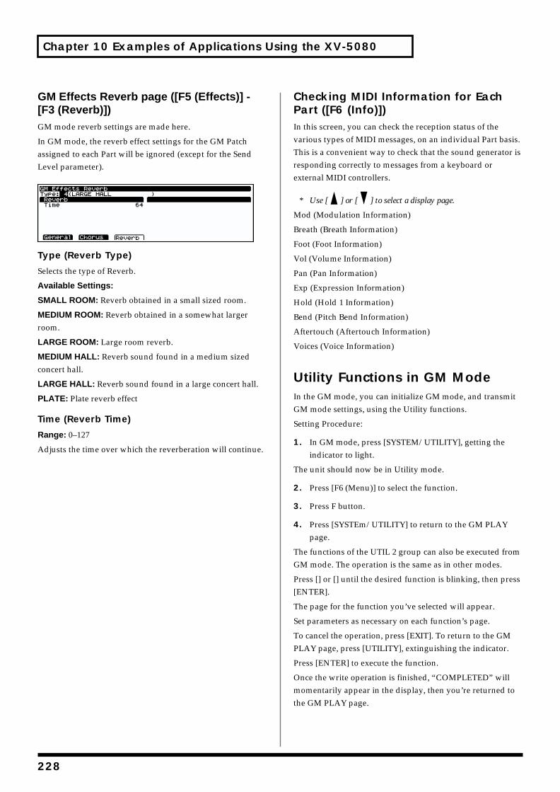
Chapter 10 Examples of Applications Using the XV-5080
GM Effects Reverb page ([F5 (Effects)] - [F3 (Reverb)])GM mode reverb settings are made here.
In GM mode, the reverb effect settings for the GM Patch assigned to each Part will be ignored (except for the Send Level parameter).fig.10-010.e_70
Type (Reverb Type)
Selects the type of Reverb.
Available Settings:
SMALL ROOM: Reverb obtained in a small sized room.
MEDIUM ROOM: Reverb obtained in a somewhat larger room.
LARGE ROOM: Large room reverb.
MEDIUM HALL: Reverb sound found in a medium sized concert hall.
LARGE HALL: Reverb sound found in a large concert hall.
PLATE: Plate reverb effect
Time (Reverb Time)
Range: 0–127
Adjusts the time over which the reverberation will continue.
Checking MIDI Information for Each Part ([F6 (Info)])In this screen, you can check the reception status of the various types of MIDI messages, on an individual Part basis. This is a convenient way to check that the sound generator is responding correctly to messages from a keyboard or external MIDI controllers.
* Use [ ] or [ ] to select a display page.
Mod (Modulation Information)
Breath (Breath Information)
Foot (Foot Information)
Vol (Volume Information)
Pan (Pan Information)
Exp (Expression Information)
Hold (Hold 1 Information)
Bend (Pitch Bend Information)
Aftertouch (Aftertouch Information)
Voices (Voice Information)
Utility Functions in GM ModeIn the GM mode, you can initialize GM mode, and transmit GM mode settings, using the Utility functions.
Setting Procedure:
1. In GM mode, press [SYSTEM/UTILITY], getting the indicator to light.
The unit should now be in Utility mode.
2. Press [F6 (Menu)] to select the function.
3. Press F button.
4. Press [SYSTEm/UTILITY] to return to the GM PLAY page.
The functions of the UTIL 2 group can also be executed from GM mode. The operation is the same as in other modes.
Press [] or [] until the desired function is blinking, then press [ENTER].
The page for the function you’ve selected will appear.
Set parameters as necessary on each function’s page.
To cancel the operation, press [EXIT]. To return to the GM PLAY page, press [UTILITY], extinguishing the indicator.
Press [ENTER] to execute the function.
Once the write operation is finished, “COMPLETED” will momentarily appear in the display, then you’re returned to the GM PLAY page.
228
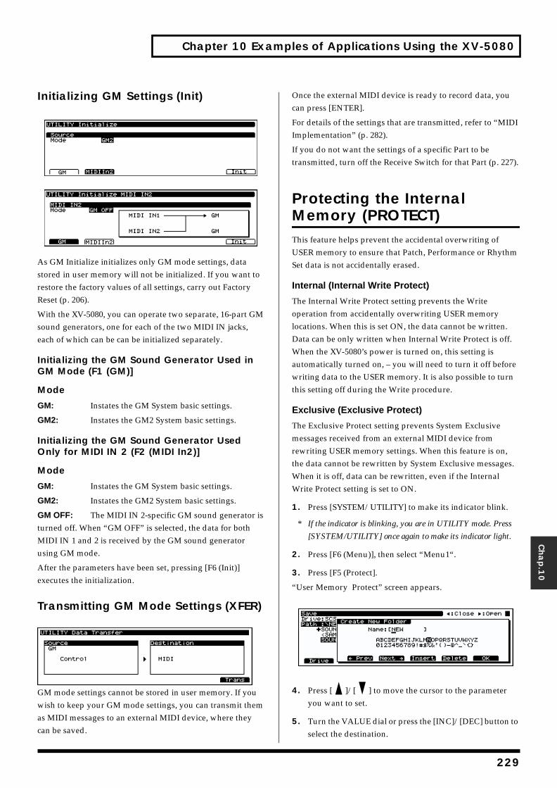
Chapter 10 Examples of Applications Using the XV-5080
Chap.1
0
Initializing GM Settings (Init)
As GM Initialize initializes only GM mode settings, data stored in user memory will not be initialized. If you want to restore the factory values of all settings, carry out Factory Reset (p. 206).
With the XV-5080, you can operate two separate, 16-part GM sound generators, one for each of the two MIDI IN jacks, each of which can be can be initialized separately.
Initializing the GM Sound Generator Used in GM Mode (F1 (GM)]
Mode
GM: Instates the GM System basic settings.
GM2: Instates the GM2 System basic settings.
Initializing the GM Sound Generator Used Only for MIDI IN 2 (F2 (MIDI In2)]
Mode
GM: Instates the GM System basic settings.
GM2: Instates the GM2 System basic settings.
GM OFF: The MIDI IN 2-specific GM sound generator is turned off. When “GM OFF” is selected, the data for both MIDI IN 1 and 2 is received by the GM sound generator using GM mode.
After the parameters have been set, pressing [F6 (Init)] executes the initialization.
Transmitting GM Mode Settings (XFER)fig.10-014.e_70
GM mode settings cannot be stored in user memory. If you wish to keep your GM mode settings, you can transmit them as MIDI messages to an external MIDI device, where they can be saved.
Once the external MIDI device is ready to record data, you can press [ENTER].
For details of the settings that are transmitted, refer to “MIDI Implementation” (p. 282).
If you do not want the settings of a specific Part to be transmitted, turn off the Receive Switch for that Part (p. 227).
Protecting the Internal Memory (PROTECT)This feature helps prevent the accidental overwriting of USER memory to ensure that Patch, Performance or Rhythm Set data is not accidentally erased.
Internal (Internal Write Protect)
The Internal Write Protect setting prevents the Write operation from accidentally overwriting USER memory locations. When this is set ON, the data cannot be written. Data can be only written when Internal Write Protect is off. When the XV-5080’s power is turned on, this setting is automatically turned on, – you will need to turn it off before writing data to the USER memory. It is also possible to turn this setting off during the Write procedure.
Exclusive (Exclusive Protect)
The Exclusive Protect setting prevents System Exclusive messages received from an external MIDI device from rewriting USER memory settings. When this feature is on, the data cannot be rewritten by System Exclusive messages. When it is off, data can be rewritten, even if the Internal Write Protect setting is set to ON.
1. Press [SYSTEM/UTILITY] to make its indicator blink.
* If the indicator is blinking, you are in UTILITY mode. Press
[SYSTEM/UTILITY] once again to make its indicator light.
2. Press [F6 (Menu)], then select “Menu1“.
3. Press [F5 (Protect].
“User Memory Protect” screen appears.
4. Press [ ]/[ ] to move the cursor to the parameter you want to set.
5. Turn the VALUE dial or press the [INC]/[DEC] button to select the destination.
229
Chapter 10 Examples of Applications Using the XV-5080
6. Press [EXIT] several times to return to the applicable PLAY page.
* Even if the Internal Write Protect setting is “ON” (write
prohibit), incoming System Exclusive messages can rewrite
the User memory data if the Exclusive Protect setting is set to
“OFF” (write permit).
230

231
Appendices
2
Troubleshooting
If no sound can be heard, or if the unit does not perform as you expect, check the following points first. If this does not resolve the problem, contact your dealer or a nearby Roland service station.
* If a message appears during operation, consult the following
section (p. 235).
No sound
Is the VOLUME lowered?• Check the VOLUME knob, and the volume settings on
the connected amp/mixer etc.
Have connections been made correctly?
• If there is sound in the headphones, it is possible that the connection cables are broken, or that the amp or mixer is malfunctioning. Check the connection cables and other devices once again.
Is the MIDI receive channel correct?• Make sure that the MIDI transmit channel of the
connected device matches the receive channel of theXV-5080.
Are the Tone, Patch and Part level settings excessively low?
• Check the level settings of each Tone, Patch and each Part.
Are Tones or Parts turned off?• Check the on/off settings of each Tone and each Part.
Are the key range settings correct?• Check the key range settings of each Tone and each Part.
Has the volume been lowered by volume/ expression messages received from an external device?
• The volume will return to normal when the power is turned on once again. When a Performance or Rhythm Set is selected, the reception status for each type of message can be viewed in the PART INFO page. (p. 166, p. 228)
Are the effect settings correct?• Check settings such as Effect On/Off, and Effect Balance
and Level.
Are the output destination settings correct?
• Check the Output Assign and MFX Output Assign settings.
Can’t select Performances
Is [RX] on?• When [RX] is on in the PERFORM PLAY page, [A]—[H]
(PART SELECT [1/9]—[8/16]) act as buttons which turn Parts on/off. Turn [RX] off.
Can’t select the Part for which to make settings
Is [RX] on?• When [RX] is on in the various Performance setting
pages, PART SELECT [1/9]—[8/16] function as buttons to switch each Part on/off. Turn [RX] off.
Pitch is wrong
Is the Master Tune setting correct?• Check the setting. (p. 209)
Is Scale Tune selected?• Check the setting. (p. 209)
Are the pitch settings for each Tone and each Part correct?
• ’Check each setting.
Have pitch bend messages received from an external device caused the pitch to “stick”?
• The pitch will return to normal when the power is turned on. If a Performance or Rhythm Set is selected, the PART INFO page allows you to check the reception status of each type of messages. (p. 166, p. 228)
32
Troubleshooting
Appen
dices
Effects do not apply
Are [MFX], [CHORUS], and [REVERB] turned off?
• Press the corresponding button to turn on the indicator.
Are the various effect settings correct?• If the send levels to each effect are at 0, effects will not
apply. Check each setting.
• Even if the send level to each effect is above 0, effects will not apply if the MFX Output Level, Chorus Level, and Reverb Level are set to 0. Check each setting.
• If Output Assign is set to PATCH for each Part of the Performance, the sound will be output according to the Output Assign settings of the Patch (for each Tone) which is assigned to those Parts. This means that if the Output Assign of (each Tone in) the Patch is set to PATCH, the MFX sound will not be output.
MIDI messages are not received correctly
Are the receive channel and receive switch settings correct?
• Check the settings for the MIDI receive channel and the various switches for reception of MIDI messages.
Are the exclusive receive settings correct?
• In order for system exclusive messages to be received, the Device ID Number must match that of the transmitting device, and the System Exclusive receive switch must be on. (p. 212) Also, if you wish to rewrite data in the USER group, the System Exclusive message Protect Switch must be turned off as well. (p. 205)
Is the DEMO PLAY page displayed?• When the DEMOPLAY page is displayed, MIDI
messages received from an external device will be ignored.
Memory Card cannot be used
Has the Memory Card (SmartMedia) been initialized?
• An uninitialized Memory Card cannot be used. Perform the initialize operation. (p. 196)
Are you using a card which the XV-5080 does not support?
• It is not possible to read the contents of a card which is for the XV-5080. Also, it is not possible to write data to a Memory Card which was formatted on a device other than the XV-5080.
Song data does not playback correctly
Are you playing back from the middle of the song?
• The beginning of a GM score song contains a GM System On message. In some cases, a GM Score cannot be played back correctly unless this message is received.
Are you playing back GS format song data?
• Since the XV-5080 is a GM system compatible sound source, there may be cases in which GS format song data will not playback correctly.
The SCSI device is not being recognized.
Could you have turned on the devices in the wrong order?
• Read “Turning On the Power” in Quick Start (P. 12), then turn on the power to the devices in the correct order.
With some SCSI devices, it can take longer than usual before they are recognized
• Should this be the case, set a higher value for the SCSI Probe Time (p. 208).First, turn off the XV-5080’s power, following the instructions in “Turning Off the Power” in Quick Start (P. 12). Then, following the instructions in “Turning On the Power” in Quick Start (P. 12), turn on
233
Troubleshooting
the power in the proper sequence. If the device is still not being recognized, even with the setting at the maximum value, then that SCSI device cannot be used with the XV-5080.
Is any SCSI ID being used for more than one device?
• If more than one device shares the same SCSI ID, then connected devices will not be correctly recognized. Follow the procedure described on p. 185 to set the SCSI IDs so that none is shared by any other device.
Commercial sampler data for other devices cannot be loaded.
• The XV-5080 is capable of loading S-700 Series and AKAI S-1000/3000 data. Other formats are not compatible. Please confirm the compatibility of any commercial data CD-ROM or other media you are using.
• AKAI S-1000/3000 data is converted when loaded to the XV-5080. There may be differences in the data compared to when it is played on the AKAI S-1000/3000.
There is no sound from the digital out, or there is noise.
• The XV-5080’s digital out is not compatible with sampling frequencies (word clock) other than 44.1 or 48 kHz. When using the XV-5080 with the digital outs synchronized to an external device, check the sampling frequency (word clock) of the external device.
• When the sampling frequency (word clock) of the XV-5080’s digital outs is synchronized to an external device, noise can sometimes be introduced as a result of the manner in which the cables carrying the signal have been run. Consequently, noise can be added to the audio signal, or in some cases, sound may not be heard. In such instances, you may be able to alleviate problems by rearranging the cables used to connect the devices.
234
Error Messages
Appen
dices
If there has been a mistake in operation, or if the XV-5080 is unable to continue processing as you directed, an error message will appear in the display. Take the appropriate action for the displayed error message. This section gives the error messages in alphabetical order.
All Data on the Drive Will Be Lost.It Will Take a Long Time.Are You Sure?Condition: When you execute a Full Format, all data on the
disk will be lost. Also, a substantial length of time is required for a full format. Is it OK to execute the operation?
Action: To cancel the operation, press [F1 (CANCEL)]. To execute the full format, press [F6 (FORMAT)].
All Data on the Drive Will Be Lost.Are You Sure?Condition: When you execute a Quick Format, all data on
the disk will be lost. Is it OK to execute the operation?
Action: To cancel the operation, press [F1 (CANCEL)]. To execute the full format, press [F6 (FORMAT)].
Battery LowSituation: The internal backup battery that is preserving
the contents of user memory has run down.Action: Consult your dealer or a nearby Roland service
station to have the battery replaced.
Cannot Find Target File!Condition: The performance specified for Auto Load was
not found.
Action 1: Make sure that the drive you specified for Auto Performance Load is connected.
Action 2: In the case of a Zip disk, insert it into the drive.
Dest Disk Incorrect!Cause: The media is of a format that cannot be written
by the XV-5080.
Action: Prepare media of a format that the XV-5080 is able to write.
Disk Full!Cause: The media is full.
Action: Either delete unneeded files (p. 198), or prepare another media.
Disk Not Ready!Cause: The media is not ready.
Action: Insert another media.
DISK, Read Error!Situation: An error occurred during read of the disk.
Action: This disk cannot be used.
DISK, Write Error!Situation: An error occurred during writing to the disk.
Action: This disk cannot be used.
File Format ErrorSituation: The XV-5080 cannot handle this file.
File I/O ErrorSituation: It was not possible to save/load a file.Action: Try the operation once again. If the same
message appears, that file has been damaged. Delete the damaged file.
FILE NAME DUPLICATE, File (file name) Already Exists!Situation: A folder with the same name already exists.Action: Delete the file bearing the same name from the
disk, and if overwriting and saving the data, merely save the file. If you do not want to delete the file with the same name from the disk, either save the file with a different name or save it to a different disk.
235
Error Messages
File Name (Folder, Volume)Format ErrorSituation: A file name has not been assigned.Action: Assign a file name.
File not FoundSituation: The specified file was not found.Action: Insert the memory card that contains the
specified file, and try the operation once again.
File Read Error!Cause 1: The data is damaged, and cannot be loaded.
Action 1: Do not use this file.
Cause 2: A problem has occurred with the connected SCSI device.
Action 2: Check the connections and power supply of the SCSI device.
File Write Error!Cause 1: The media is of a format to which the XV-5080
cannot write.
Action 1: Prepare a media that is of a format to which the XV-5080 is able to write.
Cause 2: A problem has occurred with the connected SCSI device.
Action 2: Check the connections and power supply of the SCSI device.
Folder Level Too Deep!Cause: You have exceeded the allowable depth to which
folders can be created.
Action: Create the folder at a shallower level of the folder hierarchy.
Format Completed!Condition: Formatting has been completed.
Action: Press [F6 (ACCEPT)] to erase the message.
IMPROPER DISK, This Disk is not for the XV-5080.Situation: The disk format is not one that can be used by
the XV-5080.Action: Exchange the disk with one in a format that the
XV-5080 can use, or initialize the disk for use with the XV-5080.
Illegal Format!Cause: Since the format of this file is incorrect, it cannot
be loaded.
Action: Do not use this file.
Illegal PCM Wave! Cannot Load This Wave.Cause: This file uses a type of compression that the XV-
5080 is unable to read.
Action: Use the device that created the file to convert the data into an 8 bit or 16 bit wave.
Memory Card FullSituation: There is insufficient space available on the
memory card to save the data.Action: Either insert a different memory card, or delete
unnecessary data and try the operation once again.
Memory Card I/O ErrorSituation: It is possible that the memory card has been
scratched or otherwise damaged.Action: If the memory card has been damaged, do not
use that memory card. If the same error message appears repeatedly, consult your dealer or a nearby Roland service station.
Memory Card not ReadySituation: A memory card is not inserted in the MEMORY
CARD slot.Action: Turn off the power, and insert a memory card.
236
Error Messages
Appen
dices
Memory Card Write ProtectedSituation: Since a write protect sticker is affixed to the
memory card, data cannot be saved to the card bank.
Action: Remove the write protect sticker from the memory card.
Memory Error!Cause: For some reason, wave memory cannot be read
or written.
Action: The SIMM may be damaged. If the same message appears even after reinstallation, use a different SIMM.
Memory Full!Cause: Due to insufficient wave memory, Reading is not
possible.
Action: Delete unwanted samples from the XV-5080’s memory (p. 197).
MIDI Buffer FullSituation: Due to an inordinate volume of MIDI messages
received, the XV-5080 has failed to process them properly.
Action: Reduce the amount of MIDI messages to be transmitted.
MIDI Communication ErrorSituation: A problem has occurred with the MIDI cable
connections.Action: Check that MIDI cables are not broken or pulled
out.
Number ‘****’ Will Be Deleted. Are You Sure?Condition: The sample at internal sample number ‘****’ will
be deleted. Is it OK to execute?
Action: To cancel the operation, press [F1 (CANCEL)]. To execute the deletion, press [F6 (DELETE)].
PASSWORD PROTECTED, This Zip Disk is Protected by Password!Situation: This disk is write-protected by password. The
write protection cannot be removed with the XV-5080.
Action: Either use the device with which the password protection was applied to remove the protection, or prepare a Zip disk that is not write-protected.
Path Duplicate!Cause: You are attempting to write to the same
hierarchical level.
Action: Change the writing destination.
Path Name Too Long!Cause: The path name is too long.
Action: Shorten the names of each folder. Alternatively, move the entire folder to a shallower level of the hierarchy (p. 201).
* The “path” indicates the hierarchical level at which the file is
located. It is given together with the folder name.
Performance (Patch/Partial/Sample) Full!Situation: Although the specified data was loaded, the
required free space for the Performance (Patch/Partial/Sample) is not available.
Action: Try loading again after deleting any unneeded Performances (Patches/Partials/Samples).
Receive Data ErrorSituation: A MIDI message was received incorrectly.Action: If the same error message is displayed
repeatedly, there is a problem with the MIDI messages that are being transmitted to the XV-5080.
237
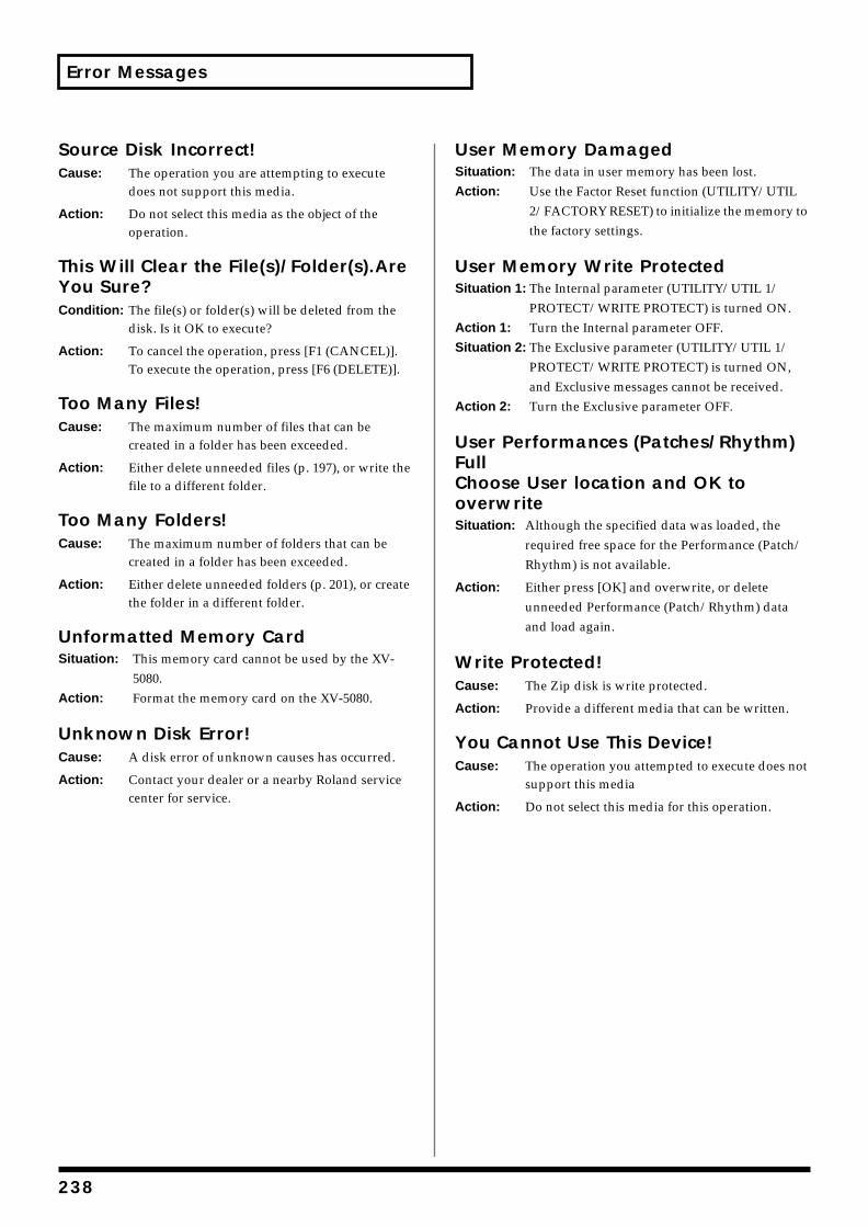
Error Messages
Source Disk Incorrect!Cause: The operation you are attempting to execute
does not support this media.
Action: Do not select this media as the object of the operation.
This Will Clear the File(s)/Folder(s).Are You Sure?Condition: The file(s) or folder(s) will be deleted from the
disk. Is it OK to execute?
Action: To cancel the operation, press [F1 (CANCEL)]. To execute the operation, press [F6 (DELETE)].
Too Many Files!Cause: The maximum number of files that can be
created in a folder has been exceeded.
Action: Either delete unneeded files (p. 197), or write the file to a different folder.
Too Many Folders!Cause: The maximum number of folders that can be
created in a folder has been exceeded.
Action: Either delete unneeded folders (p. 201), or create the folder in a different folder.
Unformatted Memory CardSituation: This memory card cannot be used by the XV-
5080.Action: Format the memory card on the XV-5080.
Unknown Disk Error!Cause: A disk error of unknown causes has occurred.
Action: Contact your dealer or a nearby Roland service center for service.
User Memory DamagedSituation: The data in user memory has been lost.Action: Use the Factor Reset function (UTILITY/UTIL
2/FACTORY RESET) to initialize the memory to the factory settings.
User Memory Write ProtectedSituation 1: The Internal parameter (UTILITY/UTIL 1/
PROTECT/WRITE PROTECT) is turned ON.Action 1: Turn the Internal parameter OFF.Situation 2: The Exclusive parameter (UTILITY/UTIL 1/
PROTECT/WRITE PROTECT) is turned ON, and Exclusive messages cannot be received.
Action 2: Turn the Exclusive parameter OFF.
User Performances (Patches/Rhythm) FullChoose User location and OK to overwriteSituation: Although the specified data was loaded, the
required free space for the Performance (Patch/Rhythm) is not available.
Action: Either press [OK] and overwrite, or delete unneeded Performance (Patch/Rhythm) data and load again.
Write Protected!Cause: The Zip disk is write protected.
Action: Provide a different media that can be written.
You Cannot Use This Device!Cause: The operation you attempted to execute does not
support this media
Action: Do not select this media for this operation.
238
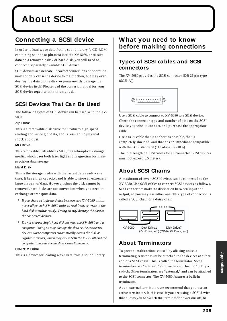
About SCSI
Appen
dices
Connecting a SCSI deviceIn order to load wave data from a sound library (a CD-ROM containing sounds or phrases) into the XV-5080, or to save data on a removable disk or hard disk, you will need to connect a separately available SCSI device.
SCSI devices are delicate. Incorrect connections or operation may not only cause the device to malfunction, but may even destroy the data on the disk, or permanently damage the SCSI device itself. Please read the owner’s manual for your SCSI device together with this manual.
SCSI Devices That Can Be UsedThe following types of SCSI device can be used with the XV-5080.
Zip Drive
This is a removable disk drive that features high-speed reading and writing of data, and is resistant to physical shock and dust.
MO Drive
This removable disk utilizes MO (magneto-optical) storage media, which uses both laser light and magnetism for high-precision data storage.
Hard Disk
This is the storage media with the fastest data read/write time. It has a high capacity, and is able to store an extremely large amount of data. However, since the disk cannot be removed, hard disks are not convenient when you need to exchange or transport data.
* If you share a single hard disk between two XV-5080 units,
never allow both XV-5080 units to read from, or write to the
hard disk simultaneously. Doing so may damage the data or
the connected devices.
* Do not share a single hard disk between the XV-5080 and a
computer. Doing so may damage the data or the connected
devices. Some computers automatically access the disk at
regular intervals, which may cause both the XV-5080 and the
computer to access the hard disk simultaneously.
CD-ROM Drive
This is a device for loading wave data from a sound library.
What you need to know before making connections
Types of SCSI cables and SCSI connectorsThe XV-5080 provides the SCSI connector (DB 25-pin type (SCSI-A)).fig.scsi-001.e
Use a SCSI cable to connect to XV-5080 to a SCSI device. Check the connector type and number of pins on the SCSI device you wish to connect, and purchase the appropriate cable.
Use a SCSI cable that is as short as possible, that is completely shielded, and that has an impedance compatible with the SCSI standard (110 ohms, +/-10%).
The total length of SCSI cables for all connected SCSI devices must not exceed 6.5 meters.
About SCSI ChainsA maximum of seven SCSI devices can be connected to the XV-5080. Use SCSI cables to connect SCSI devices as follows. SCSI connectors make no distinction between input and output, so you may use either one. This type of connection is called a SCSI chain or a daisy chain.fig.scsi-002.e
About TerminatorsTo prevent malfunctions caused by aliasing noise, a terminating resistor must be attached to the devices at either end of a SCSI chain. This is called the terminator. Some terminators are “internal,” and can be switched on/off by a switch. Other terminators are “external,” and can be attached to the SCSI connector. The XV-5080 features a built-in terminator.
As an external terminator, we recommend that you use an active terminator. In this case, if you are using a SCSI device that allows you to switch the terminator power on/off, be
XV-5080 Disk Drive1(Zip Drive, etc)
Disk Drive7(CD-ROM Drive, etc)
239
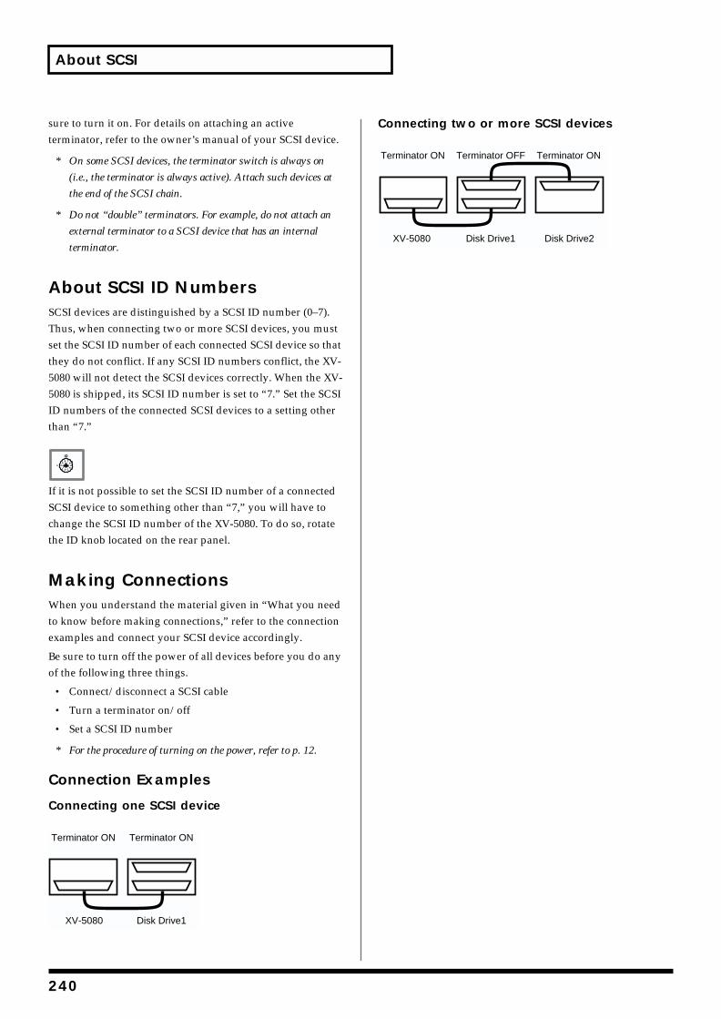
About SCSI
sure to turn it on. For details on attaching an active terminator, refer to the owner’s manual of your SCSI device.
* On some SCSI devices, the terminator switch is always on
(i.e., the terminator is always active). Attach such devices at
the end of the SCSI chain.
* Do not “double” terminators. For example, do not attach an
external terminator to a SCSI device that has an internal
terminator.
About SCSI ID NumbersSCSI devices are distinguished by a SCSI ID number (0–7). Thus, when connecting two or more SCSI devices, you must set the SCSI ID number of each connected SCSI device so that they do not conflict. If any SCSI ID numbers conflict, the XV-5080 will not detect the SCSI devices correctly. When the XV-5080 is shipped, its SCSI ID number is set to “7.” Set the SCSI ID numbers of the connected SCSI devices to a setting other than “7.”fig.scsi-003.e
If it is not possible to set the SCSI ID number of a connected SCSI device to something other than “7,” you will have to change the SCSI ID number of the XV-5080. To do so, rotate the ID knob located on the rear panel.
Making ConnectionsWhen you understand the material given in “What you need to know before making connections,” refer to the connection examples and connect your SCSI device accordingly.
Be sure to turn off the power of all devices before you do any of the following three things.
• Connect/disconnect a SCSI cable
• Turn a terminator on/off
• Set a SCSI ID number
* For the procedure of turning on the power, refer to p. 12.
Connection Examples
Connecting one SCSI devicefig.scsi-004.e
Connecting two or more SCSI devicesfig.scsi-005.e
XV-5080 Disk Drive1
Terminator ONTerminator ON
XV-5080 Disk Drive1 Disk Drive2
Terminator OFF Terminator ONTerminator ON
240
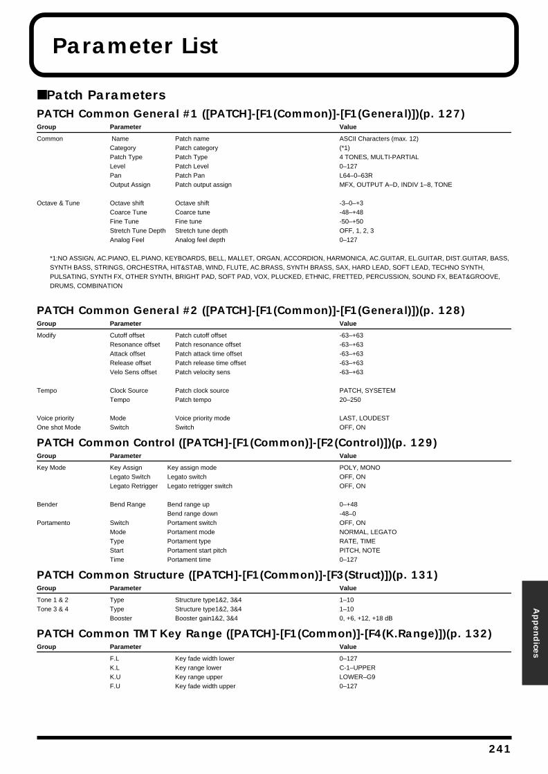
Parameter List
Appen
dices
■ Patch ParametersPATCH Common General #1 ([PATCH]-[F1(Common)]-[F1(General)])(p. 127)Group Parameter Value
Common Name Patch name ASCII Characters (max. 12)Category Patch category (*1)Patch Type Patch Type 4 TONES, MULTI-PARTIALLevel Patch Level 0–127Pan Patch Pan L64–0–63ROutput Assign Patch output assign MFX, OUTPUT A–D, INDIV 1–8, TONE
Octave & Tune Octave shift Octave shift -3–0–+3Coarce Tune Coarce tune -48–+48Fine Tune Fine tune -50–+50Stretch Tune Depth Stretch tune depth OFF, 1, 2, 3Analog Feel Analog feel depth 0–127
*1:NO ASSIGN, AC.PIANO, EL.PIANO, KEYBOARDS, BELL, MALLET, ORGAN, ACCORDION, HARMONICA, AC.GUITAR, EL.GUITAR, DIST.GUITAR, BASS, SYNTH BASS, STRINGS, ORCHESTRA, HIT&STAB, WIND, FLUTE, AC.BRASS, SYNTH BRASS, SAX, HARD LEAD, SOFT LEAD, TECHNO SYNTH, PULSATING, SYNTH FX, OTHER SYNTH, BRIGHT PAD, SOFT PAD, VOX, PLUCKED, ETHNIC, FRETTED, PERCUSSION, SOUND FX, BEAT&GROOVE, DRUMS, COMBINATION
PATCH Common General #2 ([PATCH]-[F1(Common)]-[F1(General)])(p. 128)Group Parameter Value
Modify Cutoff offset Patch cutoff offset -63–+63Resonance offset Patch resonance offset -63–+63Attack offset Patch attack time offset -63–+63Release offset Patch release time offset -63–+63Velo Sens offset Patch velocity sens -63–+63
Tempo Clock Source Patch clock source PATCH, SYSETEMTempo Patch tempo 20–250
Voice priority Mode Voice priority mode LAST, LOUDESTOne shot Mode Switch Switch OFF, ON
PATCH Common Control ([PATCH]-[F1(Common)]-[F2(Control)])(p. 129)Group Parameter Value
Key Mode Key Assign Key assign mode POLY, MONOLegato Switch Legato switch OFF, ONLegato Retrigger Legato retrigger switch OFF, ON
Bender Bend Range Bend range up 0–+48Bend range down -48–0
Portamento Switch Portament switch OFF, ONMode Portament mode NORMAL, LEGATOType Portament type RATE, TIMEStart Portament start pitch PITCH, NOTETime Portament time 0–127
PATCH Common Structure ([PATCH]-[F1(Common)]-[F3(Struct)])(p. 131)Group Parameter Value
Tone 1 & 2 Type Structure type1&2, 3&4 1–10Tone 3 & 4 Type Structure type1&2, 3&4 1–10
Booster Booster gain1&2, 3&4 0, +6, +12, +18 dB
PATCH Common TMT Key Range ([PATCH]-[F1(Common)]-[F4(K.Range)])(p. 132)Group Parameter Value
F.L Key fade width lower 0–127K.L Key range lower C-1–UPPERK.U Key range upper LOWER–G9F.U Key fade width upper 0–127
241
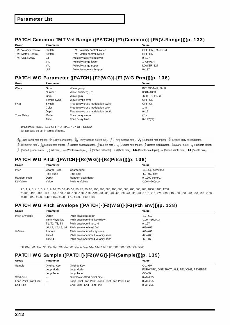
242
Parameter List
PATCH Common TM
Group Parameter
TMT Velocity Control SwitchTMT Matrix Control SwitchTMT VEL RANG L.F
V.LV.UU.F
PATCH WG Parame
Group Parameter
Wave GroupNumberGainTempo Syn
FXM SwitchColorDepth
Tone Delay ModeTime
1:NORMAL, HOLD, KEY-OFF-NO2:It can also be set in terms of no
PATCH WG Pitch ([
Group Parameter
Pitch Coarse TunFine Tune
Random pitch DepthKeyfollow Value
1:0, 1, 2, 3, 4, 5, 6, 7, 8, 9, 10, 202:-200, -190, -180, -170, -160, -1+110, +120, +130, +140, +150, +
PATCH WG Pitch En
Group Parameter
Pitch Envelope DepthTime KeyfolT1, T2, T3, L0, L1, L2, L
V-Sens AmountTime1Time 4
*1:-100, -90, -80, -70, -60, -50, -4
PATCH WG Sample
Group Parameter
Sample Original KeyLoop ModeLoop Tune
Start-Fine ---Loop Point Start Fine ---End-Fine ---
(Sixty-fourth-note triplet), (Sixty-f
(Dotted quarter note), (Half note)
(Sixteenth note), (Eighth-note tri
T Vel Range ([PATCH]-[F1(Common)]-[F5(V.Range)])(p. 133)Value
TMT Velocity control switch OFF, ON, RANDOMTMT Matrix control switch OFF, ONVelocity fade width lower 0–127Velocity range lower 1–UPPERVelocity range upper LOWER–127Velocity fade width upper 0–127
ter ([PATCH]-[F2(WG)]-[F1(WG Prm)])(p. 136)Value
Wave group INT, XP-A–H, SMPLWave number(L, R) 0001–1083Wave gain -6, 0, +6, +12 dB
c Wave tempo sync OFF, ONFrequency cross modulation switch OFF, ONFrequency cross modulation color 1–4Frequency cross modulation depth 0–16Tone delay mode (*1)Tone delay time 0–127(*2)
RMAL, KEY-OFF-DECAYtes.
PATCH]-[F2(WG)]-[F2(Pitch)])(p. 138)Value
e Coarse tune -48–+48 semitoneFine tune -50–+50 centRandom pitch depth 0–1200 cent(*1)Pitch keyfollow -200–+200(*2)
, 30, 40, 50, 60, 70, 80, 90, 100, 200, 300, 400, 500, 600, 700, 800, 900, 1000, 1100, 120050, -140, -130, -120, -110, -100, -90, -80, -70, -60, -50, -40, -30, -20, -10, 0, +10, +20, +30, +40, +50, +60, +70, +80, +90, +100, 160, +170, +180, +190, +200
velope ([PATCH]-[F2(WG)]-[F3(Pch Env)])(p. 138)Value
Pitch envelope depth -12–+12low Pitch envelope time keyfollow -100–+100(*1)T4 Pitch envelope time 1–4 0–1273, L4 Pitch envelope level 0–4 -63–+63
Pitch envelope velocity sens -63–+63Pitch envelope time1 velocity sens -63–+63Pitch envelope time4 velocity sens -63–+63
0, -30, -20, -10, 0, +10, +20, +30, +40, +50, +60, +70, +80, +90, +100
([PATCH]-[F2(WG)]-[F4(Sample)])(p. 139)Value
Original Key C-1–G9Loop Mode FORWARD, ONE SHOT, ALT, REV ONE, REVERSELoop Tune -50–50Start Point -Start Point Fine 0–/0–255Loop Point Start Point -Loop Point Start Point Fine 0–/0–255End Point - End Point Fine 0–/0–255
(Double note)(Dotted whole note),(Dotted half note),
(Dotted thirty-second note),
(Whole note), (Double-note triplet),
(Sixteenth-note triplet),(Thirty-second note),ourth note), (Thirty-second-note triplet),
(Dotted eighth note),(Quarter-note triplet),(Eighth note), (Half-note triplet),(Quarter note),
(Whole-note triplet),,
plet), (Dotted sixteenth note),
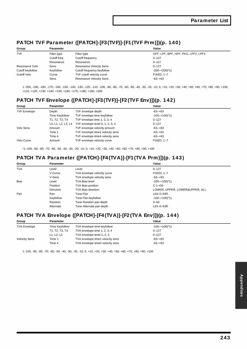
Parameter List
Appen
dices
PATCH TVF Parameter ([PATCH]-[F3(TVF)]-[F1(TVF Prm)])(p. 140)Group Parameter Value
TVF Filter type Filter type OFF, LPF, BPF, HPF, PKG, LPF2, LPF3Cutoff freq Cutoff frequency 0–127Resonance Resonance 0–127
Resonance Velo Sens Resonance Velocity Sens 0–127Cutoff keyfollow Keyfollow Cutoff frequency keyfollow -200–+200(*1)Cutoff Velo Curve TVF cutoff velocity curve FIXED, 1–7
Sens Resonance Velocity Sens -63–+63
1:-200, -190, -180, -170, -160, -150, -140, -130, -120, -110, -100, -90, -80, -70, -60, -50, -40, -30, -20, -10, 0, +10, +20, +30, +40, +50, +60, +70, +80, +90, +100, +110, +120, +130, +140, +150, +160, +170, +180, +190, +200
PATCH TVF Envelope ([PATCH]-[F3(TVF)]-[F2(TVF Env)])(p. 142)Group Parameter Value
TVF Envelope Depth TVF envelope depth -63–+63Time Keyfollow TVF envelope time keyfollow -100–+100(*1)T1, T2, T3, T4 TVF envelope time 1, 2, 3, 4 0–127L0, L1, L2, L3, L4 TVF envelope level 0, 1, 2, 3, 4 0–127
Velo Sens Amount TVF envelope velocity amount -63–+63Time 1 TVF envelope time1 velocity sens -63–+63Time 4 TVF envelope time4 velocity sens -63–+63
Velo Curve Amount TVF envelope velocity curve FIXED, 1–7
*1:-100, -90, -80, -70, -60, -50, -40, -30, -20, -10, 0, +10, +20, +30, +40, +50, +60, +70, +80, +90, +100
PATCH TVA Parameter ([PATCH]-[F4(TVA)]-[F1(TVA Prm)])(p. 143)Group Parameter Value
TVA Level Level 0–127V-Curve TVA envelope velocity curve FIXED, 1–7V-Sens TVA envelope velocity sens -63–+63
Bias Level TVA Bias level -100–+100(*1)Position TVA Bias position C-1–G9Direction TVA Bias direction LOWER, UPPER, LOWER&UPPER, ALL
Pan Pan Tone Pan L64–0–63RKeyfollow Tone Pan keyfollow -100–+100(*1)Random Tone Random pan depth 0–63Alternate Tone Alternate pan depth L63–0–63R
PATCH TVA Envelope ([PATCH]-[F4(TVA)]-[F2(TVA Env)])(p. 144)Group Parameter Value
TVA Envelope Time Keyfollow TVA envelope time keyfollow -100–+100(*1)T1, T2, T3, T4 TVA envelope time 1, 2, 3, 4 0–127L1, L2, L3 TVA envelope level 1, 2, 3 0–127
Velocity Sens Time 1 TVA envelope time1 velocity sens -63–+63Time 4 TVA envelope time4 velocity sens -63–+63
1:-100, -90, -80, -70, -60, -50, -40, -30, -20, -10, 0, +10, +20, +30, +40, +50, +60, +70, +80, +90, +100
243
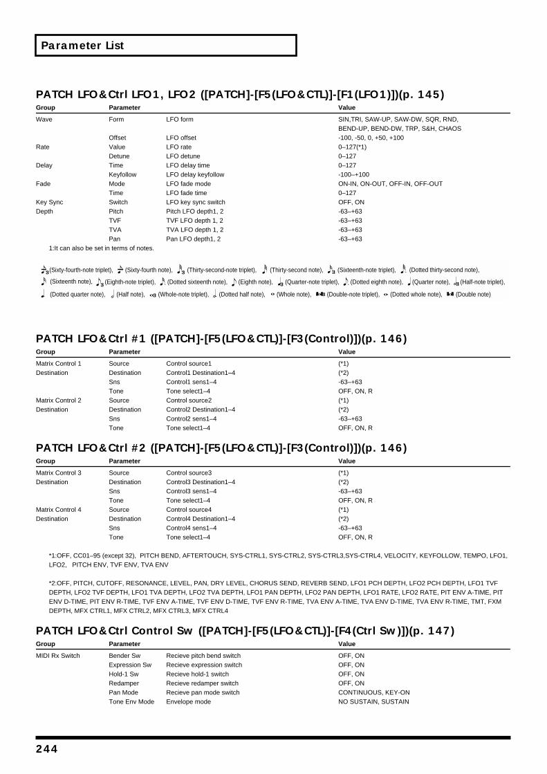
244
Parameter List
PATCH LFO&Ctrl LF
Group Parameter
Wave Form
OffsetRate Value
DetuneDelay Time
KeyfollowFade Mode
TimeKey Sync SwitchDepth Pitch
TVFTVAPan
1:It can also be set in terms of no
PATCH LFO&Ctrl #1
Group Parameter
Matrix Control 1 SourceDestination Destination
SnsTone
Matrix Control 2 SourceDestination Destination
SnsTone
PATCH LFO&Ctrl #2
Group Parameter
Matrix Control 3 SourceDestination Destination
SnsTone
Matrix Control 4 SourceDestination Destination
SnsTone
*1:OFF, CC01–95 (except 32), PLFO2, PITCH ENV, TVF ENV, T
*2:OFF, PITCH, CUTOFF, RESODEPTH, LFO2 TVF DEPTH, LFOENV D-TIME, PIT ENV R-TIME, DEPTH, MFX CTRL1, MFX CTR
PATCH LFO&Ctrl Co
Group Parameter
MIDI Rx Switch Bender SwExpression Hold-1 SwRedamperPan ModeTone Env M
(Sixty-fourth-note triplet), (Sixty-f
(Dotted quarter note), (Half note)
(Sixteenth note), (Eighth-note tri
O1, LFO2 ([PATCH]-[F5(LFO&CTL)]-[F1(LFO1)])(p. 145)Value
LFO form SIN,TRI, SAW-UP, SAW-DW, SQR, RND, BEND-UP, BEND-DW, TRP, S&H, CHAOS
LFO offset -100, -50, 0, +50, +100LFO rate 0–127(*1)LFO detune 0–127LFO delay time 0–127LFO delay keyfollow -100–+100LFO fade mode ON-IN, ON-OUT, OFF-IN, OFF-OUTLFO fade time 0–127LFO key sync switch OFF, ONPitch LFO depth1, 2 -63–+63TVF LFO depth 1, 2 -63–+63TVA LFO depth 1, 2 -63–+63Pan LFO depth1, 2 -63–+63
tes.
([PATCH]-[F5(LFO&CTL)]-[F3(Control)])(p. 146)Value
Control source1 (*1)Control1 Destination1–4 (*2)Control1 sens1–4 -63–+63Tone select1–4 OFF, ON, RControl source2 (*1)Control2 Destination1–4 (*2)Control2 sens1–4 -63–+63Tone select1–4 OFF, ON, R
([PATCH]-[F5(LFO&CTL)]-[F3(Control)])(p. 146)Value
Control source3 (*1)Control3 Destination1–4 (*2)Control3 sens1–4 -63–+63Tone select1–4 OFF, ON, RControl source4 (*1)Control4 Destination1–4 (*2)Control4 sens1–4 -63–+63Tone select1–4 OFF, ON, R
ITCH BEND, AFTERTOUCH, SYS-CTRL1, SYS-CTRL2, SYS-CTRL3,SYS-CTRL4, VELOCITY, KEYFOLLOW, TEMPO, LFO1, VA ENV
NANCE, LEVEL, PAN, DRY LEVEL, CHORUS SEND, REVERB SEND, LFO1 PCH DEPTH, LFO2 PCH DEPTH, LFO1 TVF 1 TVA DEPTH, LFO2 TVA DEPTH, LFO1 PAN DEPTH, LFO2 PAN DEPTH, LFO1 RATE, LFO2 RATE, PIT ENV A-TIME, PIT
TVF ENV A-TIME, TVF ENV D-TIME, TVF ENV R-TIME, TVA ENV A-TIME, TVA ENV D-TIME, TVA ENV R-TIME, TMT, FXM L2, MFX CTRL3, MFX CTRL4
ntrol Sw ([PATCH]-[F5(LFO&CTL)]-[F4(Ctrl Sw)])(p. 147)Value
Recieve pitch bend switch OFF, ONSw Recieve expression switch OFF, ON
Recieve hold-1 switch OFF, ONRecieve redamper switch OFF, ONRecieve pan mode switch CONTINUOUS, KEY-ON
ode Envelope mode NO SUSTAIN, SUSTAIN
(Double note)(Dotted whole note),(Dotted half note),
(Dotted thirty-second note),
(Whole note), (Double-note triplet),
(Sixteenth-note triplet),(Thirty-second note),ourth note), (Thirty-second-note triplet),
(Dotted eighth note),(Quarter-note triplet),(Eighth note), (Half-note triplet),(Quarter note),
(Whole-note triplet),,
plet), (Dotted sixteenth note),
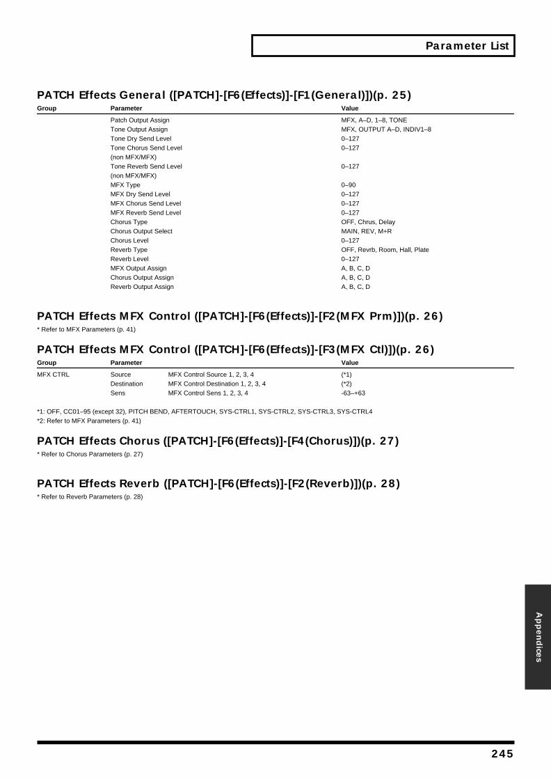
Parameter List
Appen
dices
PATCH Effects General ([PATCH]-[F6(Effects)]-[F1(General)])(p. 25)Group Parameter Value
Patch Output Assign MFX, A–D, 1–8, TONETone Output Assign MFX, OUTPUT A–D, INDIV1–8Tone Dry Send Level 0–127Tone Chorus Send Level 0–127(non MFX/MFX)Tone Reverb Send Level 0–127(non MFX/MFX)MFX Type 0–90MFX Dry Send Level 0–127MFX Chorus Send Level 0–127MFX Reverb Send Level 0–127Chorus Type OFF, Chrus, DelayChorus Output Select MAIN, REV, M+RChorus Level 0–127Reverb Type OFF, Revrb, Room, Hall, PlateReverb Level 0–127MFX Output Assign A, B, C, DChorus Output Assign A, B, C, DReverb Output Assign A, B, C, D
PATCH Effects MFX Control ([PATCH]-[F6(Effects)]-[F2(MFX Prm)])(p. 26)* Refer to MFX Parameters (p. 41)
PATCH Effects MFX Control ([PATCH]-[F6(Effects)]-[F3(MFX Ctl)])(p. 26)Group Parameter Value
MFX CTRL Source MFX Control Source 1, 2, 3, 4 (*1)Destination MFX Control Destination 1, 2, 3, 4 (*2)Sens MFX Control Sens 1, 2, 3, 4 -63–+63
*1: OFF, CC01–95 (except 32), PITCH BEND, AFTERTOUCH, SYS-CTRL1, SYS-CTRL2, SYS-CTRL3, SYS-CTRL4*2: Refer to MFX Parameters (p. 41)
PATCH Effects Chorus ([PATCH]-[F6(Effects)]-[F4(Chorus)])(p. 27)* Refer to Chorus Parameters (p. 27)
PATCH Effects Reverb ([PATCH]-[F6(Effects)]-[F2(Reverb)])(p. 28)* Refer to Reverb Parameters (p. 28)
245
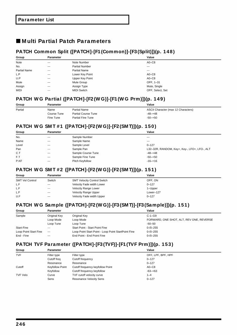
Parameter List
■ Multi Partial Patch Parameters
PATCH Common Split ([PATCH]-[F1(Common)]-[F3(Split)])(p. 148)Group Parameter Value
Note --- Note Number A0–C8No. --- Partial Number ---Partial Name --- Partial Name ---L.P --- Lower Key Point A0–C8U.P --- Upper Key Point A0–C8Mute --- Mute Group OFF, 1–31Assign --- Assign Type Mute, SingleMIDI --- MIDI Switch OFF, Select, Set
PATCH WG Partial ([PATCH]-[F2(WG)]-[F1(WG Prm)])(p. 149)Group Parameter Value
Partial Name Partial Name ASCII Character (max 12 Characters)Course Tune Partial Course Tune -48–+48Fine Tune Partial Fine Tune -50–+50
PATCH WG SMT #1 ([PATCH]-[F2(WG)]-[F2(SMT)])(p. 150)Group Parameter Value
No. --- Sample Number ---Name --- Sample Name ---Level --- Sample Level 0–127Pan --- Sample Pan L32–32R, RANDOM, Key+, Key-, LFO+, LFO-, ALTC.T --- Sample Course Tune -48–+48F.T --- Sample Fine Tune -50–+50P.KF --- Pitch Keyfollow -16–+16
PATCH WG SMT #2 ([PATCH]-[F2(WG)]-[F2(SMT)])(p. 151)Group Parameter Value
SMT Vel Control Switch SMT Velocity Control Switch OFF, ONL.F --- Velocity Fade width Lower 0–127L.F --- Velocity Range Lower 1–UpperL.F --- Velocity Range Upper Lower–127U.F --- Velocity Fade width Upper 0–127
PATCH WG Sample ([PATCH]-[F2(WG)]-[F3(SMT)]-[F3(Sample)])(p. 151)Group Parameter Value
Sample Original Key Original Key C-1–G9Loop Mode Loop Mode FORWARD, ONE SHOT, ALT, REV ONE, REVERSELoop Tune Loop Tune -50–50
Start-Fine --- Start Point - Start Point Fine 0-/0–255Loop Point Start Fine --- Loop Point Start Point - Loop Point StartPoint Fine 0-/0–255End - Fine --- End Point - End Point Fine 0-/0–255
PATCH TVF Parameter ([PATCH]-[F3(TVF)]-[F1(TVF Prm)])(p. 153)Group Parameter Value
TVF Filter type Filter type OFF, LPF, BPF, HPFCutoff freq Cutoff frequency 0–127Resonance Resonance 0–127
Cutoff Keyfollow Point Cutoff frequency keyfollow Point A0–C8Keyfollow Cutoff frequency keyfollow -63–+63
TVF Velo Curve TVF cutoff velocity curve 1–4Sens Resonance Velocity Sens 0–127
246
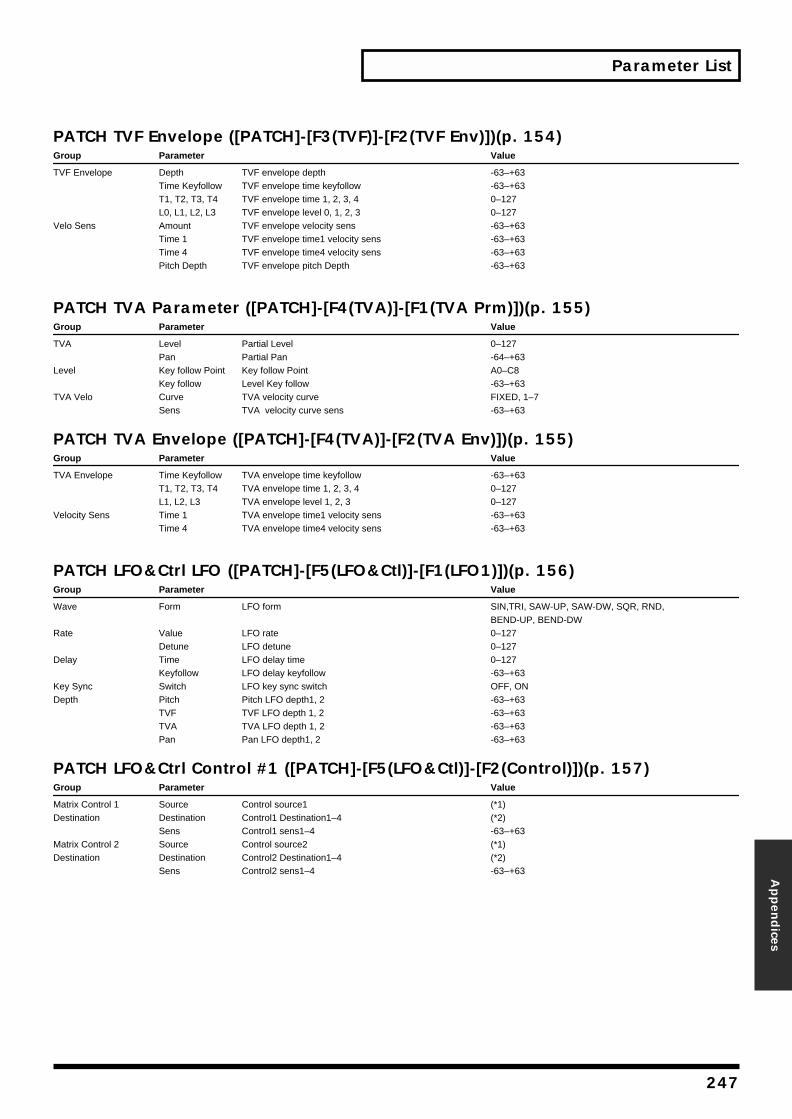
Parameter List
Appen
dices
PATCH TVF Envelope ([PATCH]-[F3(TVF)]-[F2(TVF Env)])(p. 154)Group Parameter Value
TVF Envelope Depth TVF envelope depth -63–+63Time Keyfollow TVF envelope time keyfollow -63–+63T1, T2, T3, T4 TVF envelope time 1, 2, 3, 4 0–127L0, L1, L2, L3 TVF envelope level 0, 1, 2, 3 0–127
Velo Sens Amount TVF envelope velocity sens -63–+63Time 1 TVF envelope time1 velocity sens -63–+63Time 4 TVF envelope time4 velocity sens -63–+63Pitch Depth TVF envelope pitch Depth -63–+63
PATCH TVA Parameter ([PATCH]-[F4(TVA)]-[F1(TVA Prm)])(p. 155)Group Parameter Value
TVA Level Partial Level 0–127Pan Partial Pan -64–+63
Level Key follow Point Key follow Point A0–C8Key follow Level Key follow -63–+63
TVA Velo Curve TVA velocity curve FIXED, 1–7Sens TVA velocity curve sens -63–+63
PATCH TVA Envelope ([PATCH]-[F4(TVA)]-[F2(TVA Env)])(p. 155)Group Parameter Value
TVA Envelope Time Keyfollow TVA envelope time keyfollow -63–+63T1, T2, T3, T4 TVA envelope time 1, 2, 3, 4 0–127L1, L2, L3 TVA envelope level 1, 2, 3 0–127
Velocity Sens Time 1 TVA envelope time1 velocity sens -63–+63Time 4 TVA envelope time4 velocity sens -63–+63
PATCH LFO&Ctrl LFO ([PATCH]-[F5(LFO&Ctl)]-[F1(LFO1)])(p. 156)Group Parameter Value
Wave Form LFO form SIN,TRI, SAW-UP, SAW-DW, SQR, RND, BEND-UP, BEND-DW
Rate Value LFO rate 0–127Detune LFO detune 0–127
Delay Time LFO delay time 0–127Keyfollow LFO delay keyfollow -63–+63
Key Sync Switch LFO key sync switch OFF, ONDepth Pitch Pitch LFO depth1, 2 -63–+63
TVF TVF LFO depth 1, 2 -63–+63TVA TVA LFO depth 1, 2 -63–+63Pan Pan LFO depth1, 2 -63–+63
PATCH LFO&Ctrl Control #1 ([PATCH]-[F5(LFO&Ctl)]-[F2(Control)])(p. 157)Group Parameter Value
Matrix Control 1 Source Control source1 (*1)Destination Destination Control1 Destination1–4 (*2)
Sens Control1 sens1–4 -63–+63Matrix Control 2 Source Control source2 (*1)Destination Destination Control2 Destination1–4 (*2)
Sens Control2 sens1–4 -63–+63
247
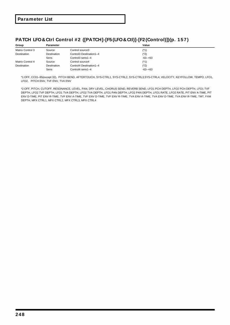
Parameter List
PATCH LFO&Ctrl Control #2 ([PATCH]-[F5(LFO&Ctl)]-[F2(Control)])(p. 157)Group Parameter Value
Matrix Control 3 Source Control source3 (*1)Destination Destination Control3 Destination1–4 (*2)
Sens Control3 sens1–4 -63–+63Matrix Control 4 Source Control source4 (*1)Destination Destination Control4 Destination1–4 (*2)
Sens Control4 sens1–4 -63–+63
*1:OFF, CC01–95(except 32), PITCH BEND, AFTERTOUCH, SYS-CTRL1, SYS-CTRL2, SYS-CTRL3,SYS-CTRL4, VELOCITY, KEYFOLLOW, TEMPO, LFO1, LFO2, PITCH ENV, TVF ENV, TVA ENV
*2:OFF, PITCH, CUTOFF, RESONANCE, LEVEL, PAN, DRY LEVEL, CHORUS SEND, REVERB SEND, LFO1 PCH DEPTH, LFO2 PCH DEPTH, LFO1 TVF DEPTH, LFO2 TVF DEPTH, LFO1 TVA DEPTH, LFO2 TVA DEPTH, LFO1 PAN DEPTH, LFO2 PAN DEPTH, LFO1 RATE, LFO2 RATE, PIT ENV A-TIME, PIT ENV D-TIME, PIT ENV R-TIME, TVF ENV A-TIME, TVF ENV D-TIME, TVF ENV R-TIME, TVA ENV A-TIME, TVA ENV D-TIME, TVA ENV R-TIME, TMT, FXM DEPTH, MFX CTRL1, MFX CTRL2, MFX CTRL3, MFX CTRL4
248

Parameter List
Appen
dices
■ Performance Parameters
PERFORMANCE Common ([PERFORMANCE]-[F1(Common)])(p. 160)Group Parameter Value
Performance Name Name Performance Name ASCII Character (12 characters max)Solo Part Select Number Solo Part Number OFF, PART1-32
PERFORMANCE Key Range ([PERFORMANCE]-[F2(K.Range)])(p. 161)Group Parameter Value
F.L Key fade width lower 0–127K.L Key range lower C-1–UPPERK.U Key range upper LOWER–G9F.U Key fade width upper 0–127
PERFORMANCE Part #1 ([PERFORMANCE]-[F3(Part)])(p. 162)Group Parameter Value
Patch Type Part type PATCH/RHYTHMGroup Patch group USER, PR-A, PR-B, PR-C, PR-D, PR-E, PR-F, PR-G, GM
XP-A–H, CD-A–HNumber Patch number 001–256
Level & Pan Level Part Level 0–127Pan Part Pan L64–0–63R
Bend Range Value Pitch bend range 0–24, PATCHTune Octave Octave shift -3–+3
Coarse Coarse tune -48–+48 semitoneFine Fine tune -50–+50 cent
Voice Reserve --- --- 0–63, FULL
PERFORMANCE Part # 2 ([PERFORMANCE]-[F3(Part)])(p. 163)Group Parameter Value
Modify Cutoff Offset Part cutoff offset -64–+63Resonance Offset Part resonance offset -64–+63Attack Time Offset Part attack time offset -64–+63Release Offset Part release time offset -64–+63Velocity Sens OffsetPart velocity sens offset -64–+63
Key Mode Mono/Poly Part MONO/POLY MONO, POLY, PATCHLegato Switch Legato switch OFF, ON, PATCH
Portamento Switch Portamento switch OFF, ON, PATCHTime Portamento Time 0–127, PATCH
PERFORMANCE MIDI #1 ([PERFORMANCE]-[F4(MIDI)])(p. 164)Group Parameter Value
Part MIDI Receive Channel MIDI Receive Channel 1–16Part Mute Switch Part Mute switch OFF, MUTEPart MIDI Receive SwitchMIDI Rx Receive switch OFF, ON
MIDI IN 1 MIDI IN 1 Receive switch OFF, ONMIDI IN 2 MIDI IN 2 Receive switch OFF, ON
249
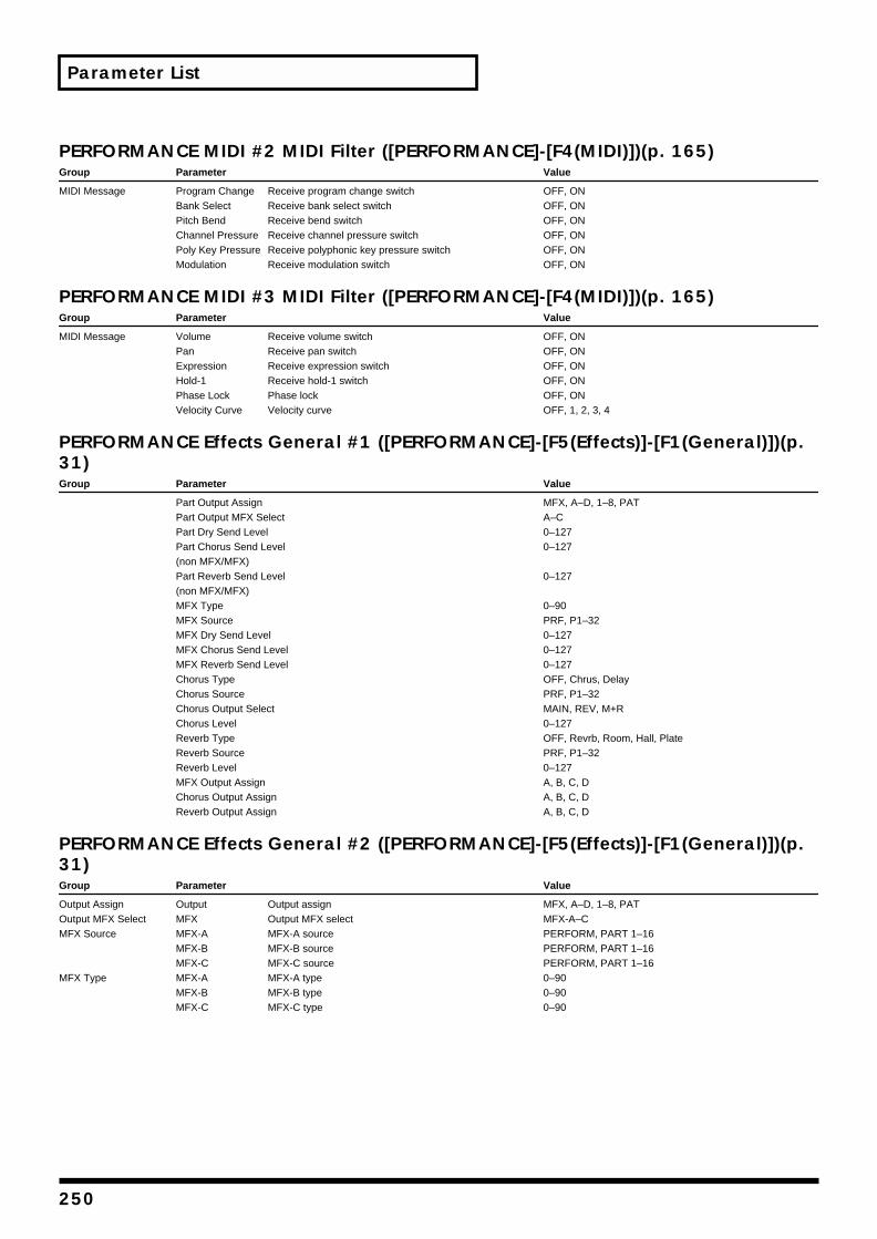
Parameter List
PERFORMANCE MIDI #2 MIDI Filter ([PERFORMANCE]-[F4(MIDI)])(p. 165)Group Parameter Value
MIDI Message Program Change Receive program change switch OFF, ONBank Select Receive bank select switch OFF, ONPitch Bend Receive bend switch OFF, ONChannel Pressure Receive channel pressure switch OFF, ONPoly Key Pressure Receive polyphonic key pressure switch OFF, ONModulation Receive modulation switch OFF, ON
PERFORMANCE MIDI #3 MIDI Filter ([PERFORMANCE]-[F4(MIDI)])(p. 165)Group Parameter Value
MIDI Message Volume Receive volume switch OFF, ONPan Receive pan switch OFF, ONExpression Receive expression switch OFF, ONHold-1 Receive hold-1 switch OFF, ONPhase Lock Phase lock OFF, ONVelocity Curve Velocity curve OFF, 1, 2, 3, 4
PERFORMANCE Effects General #1 ([PERFORMANCE]-[F5(Effects)]-[F1(General)])(p. 31)Group Parameter Value
Part Output Assign MFX, A–D, 1–8, PATPart Output MFX Select A–CPart Dry Send Level 0–127Part Chorus Send Level 0–127(non MFX/MFX)Part Reverb Send Level 0–127(non MFX/MFX)MFX Type 0–90MFX Source PRF, P1–32MFX Dry Send Level 0–127MFX Chorus Send Level 0–127MFX Reverb Send Level 0–127Chorus Type OFF, Chrus, DelayChorus Source PRF, P1–32Chorus Output Select MAIN, REV, M+RChorus Level 0–127Reverb Type OFF, Revrb, Room, Hall, PlateReverb Source PRF, P1–32Reverb Level 0–127MFX Output Assign A, B, C, DChorus Output Assign A, B, C, DReverb Output Assign A, B, C, D
PERFORMANCE Effects General #2 ([PERFORMANCE]-[F5(Effects)]-[F1(General)])(p. 31)Group Parameter Value
Output Assign Output Output assign MFX, A–D, 1–8, PATOutput MFX Select MFX Output MFX select MFX-A–CMFX Source MFX-A MFX-A source PERFORM, PART 1–16
MFX-B MFX-B source PERFORM, PART 1–16MFX-C MFX-C source PERFORM, PART 1–16
MFX Type MFX-A MFX-A type 0–90MFX-B MFX-B type 0–90MFX-C MFX-C type 0–90
250
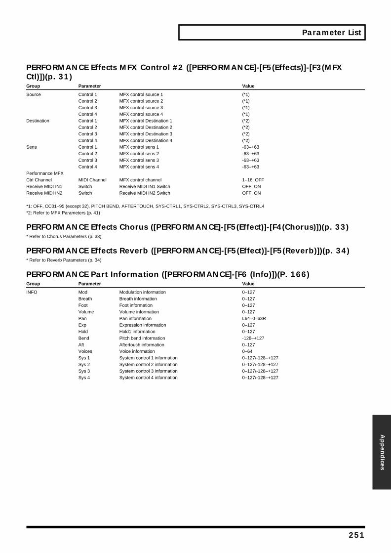
Parameter List
Appen
dices
PERFORMANCE Effects MFX Control #2 ([PERFORMANCE]-[F5(Effects)]-[F3(MFX Ctl)])(p. 31)Group Parameter Value
Source Control 1 MFX control source 1 (*1)Control 2 MFX control source 2 (*1)Control 3 MFX control source 3 (*1)Control 4 MFX control source 4 (*1)
Destination Control 1 MFX control Destination 1 (*2)Control 2 MFX control Destination 2 (*2)Control 3 MFX control Destination 3 (*2)Control 4 MFX control Destination 4 (*2)
Sens Control 1 MFX control sens 1 -63–+63Control 2 MFX control sens 2 -63–+63Control 3 MFX control sens 3 -63–+63Control 4 MFX control sens 4 -63–+63
Performance MFX Ctrl Channel MIDI Channel MFX control channel 1–16, OFFReceive MIDI IN1 Switch Receive MIDI IN1 Switch OFF, ONReceive MIDI IN2 Switch Receive MIDI IN2 Switch OFF, ON
*1: OFF, CC01–95 (except 32), PITCH BEND, AFTERTOUCH, SYS-CTRL1, SYS-CTRL2, SYS-CTRL3, SYS-CTRL4*2: Refer to MFX Parameters (p. 41)
PERFORMANCE Effects Chorus ([PERFORMANCE]-[F5(Effect)]-[F4(Chorus)])(p. 33)* Refer to Chorus Parameters (p. 33)
PERFORMANCE Effects Reverb ([PERFORMANCE]-[F5(Effect)]-[F5(Reverb)])(p. 34)* Refer to Reverb Parameters (p. 34)
PERFORMANCE Part Information ([PERFORMANCE]-[F6 (Info)])(P. 166)Group Parameter Value
INFO Mod Modulation information 0–127Breath Breath information 0–127Foot Foot information 0–127Volume Volume information 0–127Pan Pan information L64–0–63RExp Expression information 0–127Hold Hold1 information 0–127Bend Pitch bend information -128–+127Aft Aftertouch information 0–127Voices Voice information 0–64Sys 1 System control 1 information 0–127/-128–+127Sys 2 System control 2 information 0–127/-128–+127Sys 3 System control 3 information 0–127/-128–+127Sys 4 System control 4 information 0–127/-128–+127
251
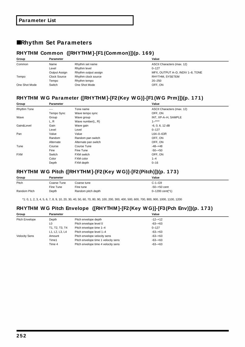
Parameter List
■ Rhythm Set Parameters
RHYTHM Common ([RHYTHM]-[F1(Common)])(p. 169)Group Parameter Value
Common Name Rhythm set name ASCII Characters (max. 12)Level Rhythm level 0–127Output Assign Rhythm output assign MFX, OUTPUT A–D, INDIV 1–8, TONE
Tempo Clock Source Rhythm clock source RHYTHM, SYSETEMTempo Rhythm tempo 20–250
One Shot Mode Switch One Shot Mode OFF, ON
RHYTHM WG Parameter ([RHYTHM]-[F2(Key WG)]-[F1(WG Prm)])(p. 171)Group Parameter Value
Rhythm Tone ---- Tone name ASCII Characters (max. 12)Tempo Sync Wave tempo sync OFF, ON
Wave Group Wave group INT, XP-A–H, SAMPLEL, R Wave number(L, R) 1–****
Gain&Level Gain Wave gain -6, 0, 6, 12 dBLevel Level 0–127
Pan Value Value L64–0–63RRandom Random pan switch OFF, ONAlternate Alternate pan switch OFF, ON
Tune Course Course Tune -48–+48Fine Fine Tune -50–+50
FXM Switch FXM switch OFF, ONColor FXM color 1–4Depth FXM depth 0–16
RHYTHM WG Pitch ([RHYTHM]-[F2(Key WG)]-[F2(Pitch)])(p. 173)Group Parameter Value
Pitch Coarse Tune Coarse tune C-1–G9Fine Tune Fine tune -50–+50 cent
Random Pitch Depth Random pitch depth 0–1200 cent(*1)
*1: 0, 1, 2, 3, 4, 5, 6, 7, 8, 9, 10, 20, 30, 40, 50, 60, 70, 80, 90, 100, 200, 300, 400, 500, 600, 700, 800, 900, 1000, 1100, 1200
RHYTHM WG Pitch Envelope ([RHYTHM]-[F2(Key WG)]-[F3(Pch Env)])(p. 173)Group Parameter Value
Pitch Envelope Depth Pitch envelope depth -12–+12L0 Pitch envelope level 0 -63–+63T1, T2, T3, T4 Pitch envelope time 1–4 0–127L1, L2, L3, L4 Pitch envelope level 1–4 -63–+63
Velocity Sens Amount Pitch envelope velocity sens -63–+63Time1 Pitch envelope time 1 velocity sens -63–+63Time 4 Pitch envelope time 4 velocity sens -63–+63
252

Parameter List
Appen
dices
RHYTHM WG WMT Vel Range ([RHYTHM]-[F2(Key WG)]-[F4(V.Range)])(p. 174)Group Parameter Value
Velocity Control Switch Velocity Control Switch OFF, ON, RANDOML.F Velocity fade width lower 0–127V.L Velocity range lower 1–UPPERV.U Velocity range upper LOWER–127U.F Velocity fade width upper 0–127
RHYTHM WG Sample ([RHYTHM]-[F2(Key WG)]-[F5(Sample)])(p. 174)Group Parameter Value
Sample Original Key Original Key C-1–G9Loop Mode Loop Mode FORWARD, ONE SHOT, ALT, REV ONE, REVERSELoop Tune Loop Tune -50–50
Start-Fine --- Start Point -Start Point Fine 0–/0–255Loop Point Start Fine --- Loop Point Start Point -Loop Point Start Point Fine 0–/0–255End-Fine --- End Point - End Point Fine 0–/0–255
RHYTHM TVF Parameter ([RHYTHM]-[F3(Key TVF)]-[F1(TVF Prm)])(p. 175)Group Parameter Value
TVF FILTER Type Filter type OFF, LPF, BPF, HPF, PKG, LPF2, LPF3Cutoff Cutoff frequency 0–127Resonance Resonance 0–127
TVF VELOCITY V-Cutoff TVF cutoff velocity sens -63–+63V-Curve TVF cutoff velocity curve FIXED, 1–7V-Resonance TVF resonance velocity sens -63–+63
RHYTHM TVF Envelope ([RHYTHM]-[F3(Key TVF)]-[F2(TVF Env)])(p. 177)Group Parameter Value
TVF ENVELOPE Depth TVF Envelope depth -63–+63V-Sens TVF envelope velocity sens -63–+63V-Curve TVF envelope velocity curve FIXED, 1–7V-T1 TVF envelope time 1 velocity sens -63–+63V-T4 TVF envelope time 4 velocity sens -63–+63L0 TVF envelope level 0 0–127T1, T2, T3, T4 TVF envelope time 1, 2, 3, 4 0–127L1, L2, L3, L4 TVF envelope level 1, 2, 3, 4 0–127
RHYTHM TVA Parameter ([RHYTHM]-[F4(Key TVA)]-[F1(TVA Prm)])(p. 177)Group Parameter Value
TVA Level Level 0–127Pan Pan L64–0–63RRandom Random pan depth 0–63Alternate Alternate pan depth L63–0–63R
TVA VELOCITY Velocity Sens TVA envelope velocity sens -63–+63Velocity Curve TVA envelope velocity curve FIXED, 1–7
RHYTHM TVA Envelope ([RHYTHM]-[F4(Key TVA)]-[F2(TVA Env)])(p. 178)Group Parameter Value
TVA TIME ENV V-T1 TVA envelope time 1 velocity sens -63–+63V-T4 TVA envelope time 4 velocity sens -63–+63
TVA ENVELOPE T1–4 TVA envelope time 1–4 0–127L1–3 TVA envelope level 1–3 0–127
253
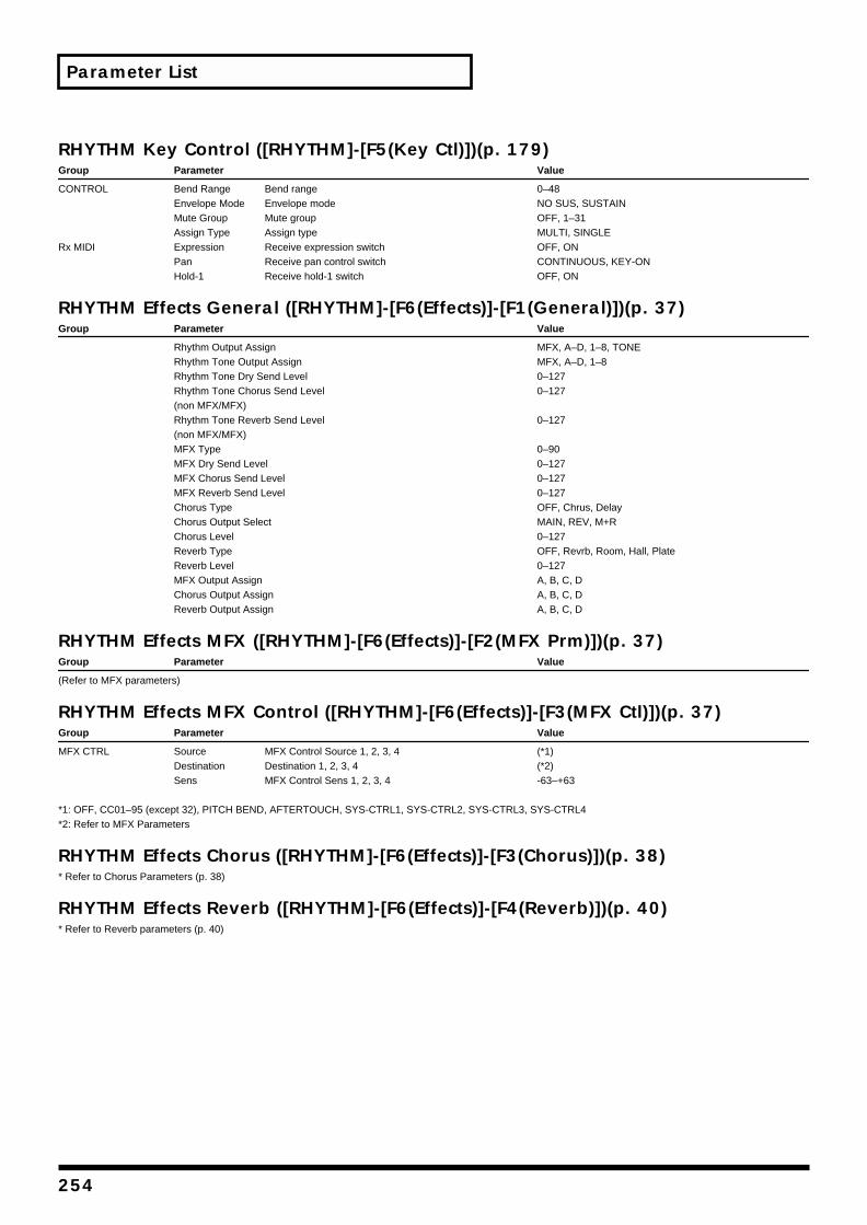
Parameter List
RHYTHM Key Control ([RHYTHM]-[F5(Key Ctl)])(p. 179)Group Parameter Value
CONTROL Bend Range Bend range 0–48Envelope Mode Envelope mode NO SUS, SUSTAINMute Group Mute group OFF, 1–31Assign Type Assign type MULTI, SINGLE
Rx MIDI Expression Receive expression switch OFF, ONPan Receive pan control switch CONTINUOUS, KEY-ONHold-1 Receive hold-1 switch OFF, ON
RHYTHM Effects General ([RHYTHM]-[F6(Effects)]-[F1(General)])(p. 37)Group Parameter Value
Rhythm Output Assign MFX, A–D, 1–8, TONERhythm Tone Output Assign MFX, A–D, 1–8Rhythm Tone Dry Send Level 0–127Rhythm Tone Chorus Send Level 0–127(non MFX/MFX)Rhythm Tone Reverb Send Level 0–127(non MFX/MFX)MFX Type 0–90MFX Dry Send Level 0–127MFX Chorus Send Level 0–127MFX Reverb Send Level 0–127Chorus Type OFF, Chrus, DelayChorus Output Select MAIN, REV, M+RChorus Level 0–127Reverb Type OFF, Revrb, Room, Hall, PlateReverb Level 0–127MFX Output Assign A, B, C, DChorus Output Assign A, B, C, DReverb Output Assign A, B, C, D
RHYTHM Effects MFX ([RHYTHM]-[F6(Effects)]-[F2(MFX Prm)])(p. 37)Group Parameter Value
(Refer to MFX parameters)
RHYTHM Effects MFX Control ([RHYTHM]-[F6(Effects)]-[F3(MFX Ctl)])(p. 37)Group Parameter Value
MFX CTRL Source MFX Control Source 1, 2, 3, 4 (*1)Destination Destination 1, 2, 3, 4 (*2)Sens MFX Control Sens 1, 2, 3, 4 -63–+63
*1: OFF, CC01–95 (except 32), PITCH BEND, AFTERTOUCH, SYS-CTRL1, SYS-CTRL2, SYS-CTRL3, SYS-CTRL4*2: Refer to MFX Parameters
RHYTHM Effects Chorus ([RHYTHM]-[F6(Effects)]-[F3(Chorus)])(p. 38)* Refer to Chorus Parameters (p. 38)
RHYTHM Effects Reverb ([RHYTHM]-[F6(Effects)]-[F4(Reverb)])(p. 40)* Refer to Reverb parameters (p. 40)
254
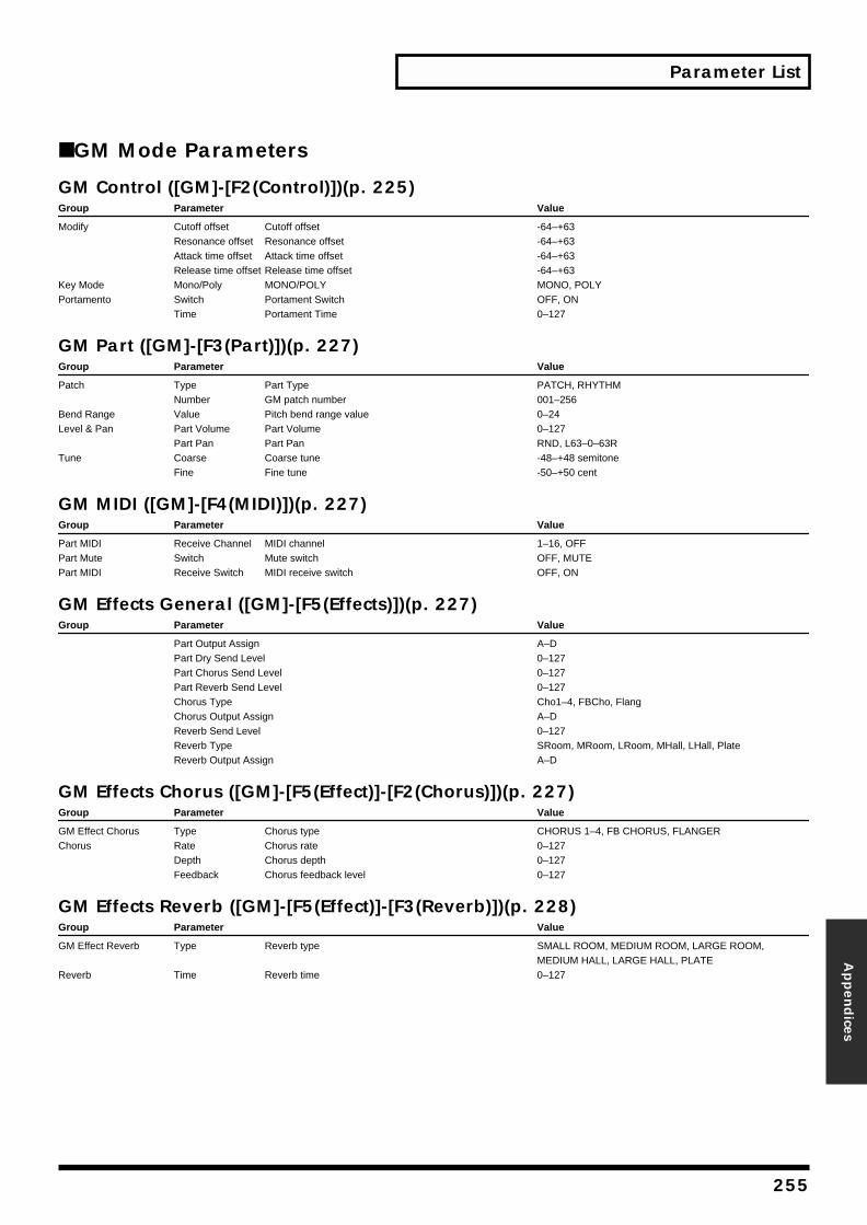
Parameter List
Appen
dices
■ GM Mode Parameters
GM Control ([GM]-[F2(Control)])(p. 225)Group Parameter Value
Modify Cutoff offset Cutoff offset -64–+63Resonance offset Resonance offset -64–+63Attack time offset Attack time offset -64–+63Release time offset Release time offset -64–+63
Key Mode Mono/Poly MONO/POLY MONO, POLYPortamento Switch Portament Switch OFF, ON
Time Portament Time 0–127
GM Part ([GM]-[F3(Part)])(p. 227)Group Parameter Value
Patch Type Part Type PATCH, RHYTHMNumber GM patch number 001–256
Bend Range Value Pitch bend range value 0–24Level & Pan Part Volume Part Volume 0–127
Part Pan Part Pan RND, L63–0–63RTune Coarse Coarse tune -48–+48 semitone
Fine Fine tune -50–+50 cent
GM MIDI ([GM]-[F4(MIDI)])(p. 227)Group Parameter Value
Part MIDI Receive Channel MIDI channel 1–16, OFFPart Mute Switch Mute switch OFF, MUTEPart MIDI Receive Switch MIDI receive switch OFF, ON
GM Effects General ([GM]-[F5(Effects)])(p. 227)Group Parameter Value
Part Output Assign A–DPart Dry Send Level 0–127Part Chorus Send Level 0–127Part Reverb Send Level 0–127Chorus Type Cho1–4, FBCho, FlangChorus Output Assign A–DReverb Send Level 0–127Reverb Type SRoom, MRoom, LRoom, MHall, LHall, PlateReverb Output Assign A–D
GM Effects Chorus ([GM]-[F5(Effect)]-[F2(Chorus)])(p. 227)Group Parameter Value
GM Effect Chorus Type Chorus type CHORUS 1–4, FB CHORUS, FLANGERChorus Rate Chorus rate 0–127
Depth Chorus depth 0–127Feedback Chorus feedback level 0–127
GM Effects Reverb ([GM]-[F5(Effect)]-[F3(Reverb)])(p. 228)Group Parameter Value
GM Effect Reverb Type Reverb type SMALL ROOM, MEDIUM ROOM, LARGE ROOM, MEDIUM HALL, LARGE HALL, PLATE
Reverb Time Reverb time 0–127
255
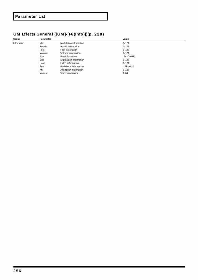
Parameter List
GM Effects General ([GM]-[F6(Info)])(p. 228)Group Parameter Value
Infometion Mod Modulation information 0–127Breath Breath information 0–127Foot Foot information 0–127Volume Volume information 0–127Pan Pan information L64–0–63RExp Expression information 0–127Hold Hold1 information 0–127Bend Pitch bend information -128–+127Aft Aftertouch information 0–127Voices Voice information 0–64
256
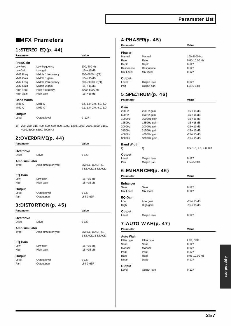
Parameter List
Appen
dices
■ MFX Prameters
1:STEREO EQ(p. 44)Parameter Value
Freq/GainLowFreq Low frequency 200, 400 HzLowGain Low gain -15–+15 dBMid1 Freq Middle 1 frequency 200–8000Hz(*1)Mid1 Gain Middle 1 gain -15–+15 dBMid2 Freq Middle 2 frequency 200–8000 Hz(*1)Mid2 Gain Middle 2 gain -15–+15 dBHigh Freq High frequency 4000, 8000 HzHigh Gain High gain -15–+15 dB
Band WidthMid1 Q Mid1 Q 0.5, 1.0, 2.0, 4.0, 8.0Mid2 Q Mid2 Q 0.5, 1.0, 2.0, 4.0, 8.0
OutputLevel Output level 0–127
1: 200, 250, 315, 400, 500, 630, 800, 1000, 1250, 1600, 2000, 2500, 3150, 4000, 5000, 6300, 8000 Hz
2:OVERDRIVE(p. 44)Parameter Value
OverdriveDrive Drive 0-127
Amp simulatorType Amp simulator type SMALL, BUILT-IN,
2-STACK, 3-STACK
EQ GainLow Low gain -15-+15 dBHigh High gain -15-+15 dB
OutputLevel Output level 0-127Pan Output pan L64-0-63R
3:DISTORTION(p. 45)Parameter Value
OverdriveDrive Drive 0-127
Amp simulatorType Amp simulator type SMALL, BUILT-IN,
2-STACK, 3-STACK
EQ GainLow Low gain -15-+15 dBHigh High gain -15-+15 dB
OutputLevel Output level 0-127Pan Output pan L64-0-63R
4:PHASER(p. 45)Parameter Value
PhaserManual Manual 100-8000 HzRate Rate 0.05-10.00 HzDepth Depth 0-127Resonance Resonance 0-127Mix Level Mix level 0-127
OutputLevel Output level 0-127Pan Output pan L64-0-63R
5:SPECTRUM(p. 46)Parameter Value
Gain250Hz 250Hz gain -15-+15 dB500Hz 500Hz gain -15-+15 dB1000Hz 1000Hz gain -15-+15 dB1250Hz 1250Hz gain -15-+15 dB2000Hz 2000Hz gain -15-+15 dB3150Hz 3150Hz gain -15-+15 dB4000Hz 4000Hz gain -15-+15 dB8000Hz 8000Hz gain -15-+15 dB
Band WidthQ Q 0.5, 1.0, 2.0, 4.0, 8.0
OutputLevel Output level 0-127Pan Output pan L64-0-63R
6:ENHANCER(p. 46)Parameter Value
EnhancerSens Sens 0-127Mix Level Mix level 0-127
EQ GainLow Low gain -15-+15 dBHigh High gain -15-+15 dB
OutputLevel Output level 0-127
7:AUTO WAH(p. 47)Parameter Value
Auto WahFilter type Filter type LPF, BPFSens Sens 0-127Manual Manual 0-127Peak Peak 0-127Rate Rate 0.05-10.00 HzDepth Depth 0-127
OutputLevel Output level 0-127
257

Parameter List
8:ROTARY(p. 47)Parameter Value
RotarySpeed Speed SLOW, FAST
WooferSlow Rate Low frequency slow rate 0.05-10.00 HzFast Rate Low frequency fast rate 0.05-10.00 HzAcceleration Low frequency acceleration 0-15Level Low frequency level 0-127
SeparationSeparation 0-127
TweeterSlow Rate High frequency slow rate 0.05-10.00 HzFast Rate High frequency fast rate 0.05-10.00 HzAccelerationl High frequency acceleration 0-15Level High frequency level 0-127
OutputLevel Output level 0-127
9:COMPRESSOR(p. 48)Parameter Value
CompressorAttack Attack 0-127Sustain Sustain 0-127Post Gain Post gain 0, +6, +12, +18 dB
EQ GainLow Low gain -15-+15 dBHigh High gain -15-+15 dB
OutputLevel Output level 0-127Pan Output pan L64-0-63R
10:LIMITER(p. 48)Parameter Value
LimiterThreshold Threshold level 0-127Ratio Compression ratio 1.5:1, 2:1, 4:1, 100:1Release Release time 0-127Post gain Post gain 0, +6, +12, +18 dB
EQ GainLow Low gain -15-+15 dBHigh High gain -15-+15 dB
OutputLevel Output level 0-127Pan Output pan L64-0-63R
11:HEXA-CHORUS(p. 49)Parameter Value
Hexa ChorusRate Rate 0.05-10.00 HzDepth Depth 0-127Depth Dev Depth deviation -20-+20Pre Delay Pre delay time 0.0-100.0 msPre Delay Dev Pre delay deviation 0-127Pan Dev Pan deviation 0-127
BalanceEffect balance D100:0W-D0:100W
OutputLevel Output level 0-127
12:TREMOLO CHORUS(p. 49)Parameter Value
ChorusRate Chorus rate 0.05-10.00 HzDepth Chorus depth 0-127Pre Delay Pre delay time 0.0-100.0 ms
TremoloRate Tremolo rate 0.05-10.00 HzPhase Tremolo phase 0-180 degreeSeparation Tremolo separation 0-127
BalanceEffect balance D100:0W-D0:100W
OutputLevel Output level 0-127
13:SPACE-D(p. 50)Parameter Value
ChorusRate Rate 0.05-10.00 HzDepth Depth 0-127Phase Phase 0-180 degreePre Delay Pre delay time 0.0-100.0 ms
EQ GainLow Low gain -15-+15 dBHigh High gain -15-+15 dB
BalanceEffect balance D100:0W-D0:100W
OutputLevel Output level 0-127
14:STEREO CHORUS(p. 50)Parameter Value
ChorusRate Rate 0.05-10.00 HzDepth Depth 0-127Phase Phase 0-180 degreePre Delay Pre delay time 0.0-100.0 ms
FilterType Filter type OFF, LPF, HPFCutoff Cutoff frequency 200-8000 Hz (*1)
EQ GainLow Low gain -15-+15 dBHigh High gain -15-+15 dB
BalanceEffect balance D100:0W-D0:100W
OutputLevel Output level 0-127
1: 200, 250, 315, 400, 500, 630, 800, 1000, 1250, 1600, 2000, 2500, 3150, 4000, 5000, 6300, 8000 Hz
258

Parameter List
Appen
dices
15:STEREO FLANGER(p. 51)Parameter Value
FlangerRate Rate 0.05-10.00 HzDepth Depth 0-127Feedback Feedback level -98-+98%Phase Phase 0-180 degreePre Delay Pre delay time 0.0-100.0 ms
FilterType Filter type OFF, LPF, HPFCutoff Cutoff frequency 200-8000 Hz (*1)
EQ GainLow Low gain -15-+15 dBHigh High gain -15-+15 dB
BalanceEffect balance D100:0W-D0:100W
OutputLevel Output level 0-127
1: 200, 250, 315, 400, 500, 630, 800, 1000, 1250, 1600, 2000, 2500, 3150, 4000, 5000, 6300, 8000 Hz
16:STEP FLANGER(p. 51)Parameter Value
FlangerRate Rate 0.05-10.00 HzDepth Depth 0-127Feedback Feedback level -98-+98%Phase Phase 0-180 degreePre Delay Pre delay time 0.0-100.0 ms
Step RateStep rate 0.10-20.00 Hz, note *1
EQ GainLow Low gain -15-+15 dBHigh High gain -15-+15 dB
BalanceEffect balance D100:0W-D0:100W
OutputLevel Output level 0-127
17:STEREO DELAY(p. 52)Parameter Value
DelayLeft Delay time left 0.0-500.0 msRight Delay time right 0.0-500.0 msHF Damp HF damp 200-8000 Hz, Feedback Feedback level -98-+98%FBK Mode Feedback mode NORMAL, CROSS
PhasePhase Left Feedback phase left NORMAL, INVERTPhase Right Feedback phase right NORMAL, INVERT
BYPASS (*1)
EQ GainLow Low gain -15-+15 dBHigh High gain -15-+15 dB
BalanceEffect balance D100:0W-D0:100W
OutputLevel Output level 0-127
1: 200, 250, 315, 400, 500, 630, 800, 1000, 1250, 1600, 2000, 2500, 3150, 4000, 5000, 6300, 8000 Hz, BYPASS
18:MODULATION DELAY(p. 53)Parameter Value
DelayLeft Delay time left 0.0-500.0 msRight Delay time right 0.0-500.0 msHF Damp HF damp 200-8000 Hz, Feedback Feedback level -98-+98%FBK Mode Feedback mode NORMAL, CROSS
ModulationRate Rate 0.05-10.00 HzDepth Depth 0-127Phase Phase 0-180 degree
BYPASS (*1)
EQ GainLow Low gain -15-+15 dBHigh High gain -15-+15 dB
BalanceEffect balance D100:0W-D0:100W
LevelLevel Output level 0-127
1: 200, 250, 315, 400, 500, 630, 800, 1000, 1250, 1600, 2000, 2500, 3150, 4000, 5000, 6300, 8000 Hz, BYPASS
19:TRIPLE TAP DELAY(p. 54)Parameter Value
DelayCenter Delay time center 200-1000 ms, note *1Left Delay time left 200-1000 ms, note *1Right Delay time right 200-1000 ms, note *1HF Damp HF damp 200-8000 Hz,
BYPASS (*1)Feedback Feedback level -98-+98%
Delay LevelCenter Center level 0-127Left Left level 0-127Right Right level 0-127
EQ GainLow Low gain -15-+15 dBHigh High gain -15-+15 dB
BalanceEffect balance D100:0W-D0:100W
LevelLevel Output level 0-127
1: 200, 250, 315, 400, 500, 630, 800, 1000, 1250, 1600, 2000, 2500, 3150, 4000, 5000, 6300, 8000 Hz, BYPASS
259
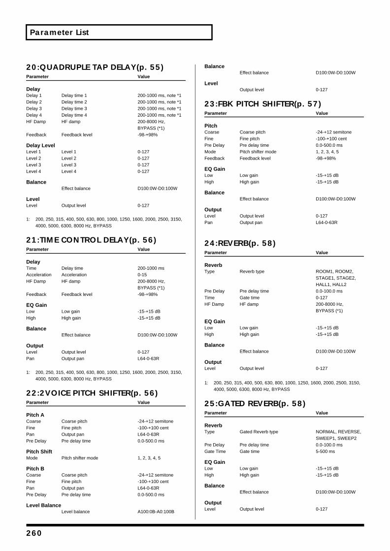
Parameter List
20:QUADRUPLE TAP DELAY(p. 55)Parameter Value
DelayDelay 1 Delay time 1 200-1000 ms, note *1Delay 2 Delay time 2 200-1000 ms, note *1Delay 3 Delay time 3 200-1000 ms, note *1Delay 4 Delay time 4 200-1000 ms, note *1HF Damp HF damp 200-8000 Hz,
BYPASS (*1)Feedback Feedback level -98-+98%
Delay LevelLevel 1 Level 1 0-127Level 2 Level 2 0-127Level 3 Level 3 0-127Level 4 Level 4 0-127
BalanceEffect balance D100:0W-D0:100W
LevelLevel Output level 0-127
1: 200, 250, 315, 400, 500, 630, 800, 1000, 1250, 1600, 2000, 2500, 3150, 4000, 5000, 6300, 8000 Hz, BYPASS
21:TIME CONTROL DELAY(p. 56)Parameter Value
DelayTime Delay time 200-1000 msAcceleration Acceleration 0-15HF Damp HF damp 200-8000 Hz,
BYPASS (*1)Feedback Feedback level -98-+98%
EQ GainLow Low gain -15-+15 dBHigh High gain -15-+15 dB
BalanceEffect balance D100:0W-D0:100W
OutputLevel Output level 0-127Pan Output pan L64-0-63R
1: 200, 250, 315, 400, 500, 630, 800, 1000, 1250, 1600, 2000, 2500, 3150, 4000, 5000, 6300, 8000 Hz, BYPASS
22:2VOICE PITCH SHIFTER(p. 56)Parameter Value
Pitch ACoarse Coarse pitch -24-+12 semitoneFine Fine pitch -100-+100 centPan Output pan L64-0-63RPre Delay Pre delay time 0.0-500.0 ms
Pitch ShiftMode Pitch shifter mode 1, 2, 3, 4, 5
Pitch BCoarse Coarse pitch -24-+12 semitoneFine Fine pitch -100-+100 centPan Output pan L64-0-63RPre Delay Pre delay time 0.0-500.0 ms
Level BalanceLevel balance A100:0B-A0:100B
BalanceEffect balance D100:0W-D0:100W
LevelOutput level 0-127
23:FBK PITCH SHIFTER(p. 57)Parameter Value
PitchCoarse Coarse pitch -24-+12 semitoneFine Fine pitch -100-+100 centPre Delay Pre delay time 0.0-500.0 msMode Pitch shifter mode 1, 2, 3, 4, 5Feedback Feedback level -98-+98%
EQ GainLow Low gain -15-+15 dBHigh High gain -15-+15 dB
BalanceEffect balance D100:0W-D0:100W
OutputLevel Output level 0-127Pan Output pan L64-0-63R
24:REVERB(p. 58)Parameter Value
ReverbType Reverb type ROOM1, ROOM2,
STAGE1, STAGE2, HALL1, HALL2
Pre Delay Pre delay time 0.0-100.0 msTime Gate time 0-127HF Damp HF damp 200-8000 Hz,
BYPASS (*1)
EQ GainLow Low gain -15-+15 dBHigh High gain -15-+15 dB
BalanceEffect balance D100:0W-D0:100W
OutputLevel Output level 0-127
1: 200, 250, 315, 400, 500, 630, 800, 1000, 1250, 1600, 2000, 2500, 3150, 4000, 5000, 6300, 8000 Hz, BYPASS
25:GATED REVERB(p. 58)Parameter Value
ReverbType Gated Reverb type NORMAL, REVERSE,
SWEEP1, SWEEP2Pre Delay Pre delay time 0.0-100.0 msGate Time Gate time 5-500 ms
EQ GainLow Low gain -15-+15 dBHigh High gain -15-+15 dB
BalanceEffect balance D100:0W-D0:100W
OutputLevel Output level 0-127
260
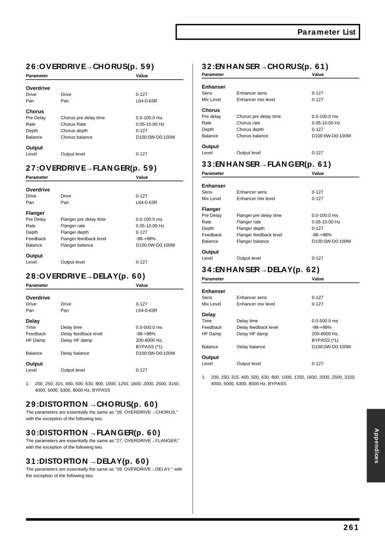
Parameter List
Appen
dices
26:OVERDRIVE→CHORUS(p. 59)Parameter Value
OverdriveDrive Drive 0-127Pan Pan L64-0-63R
ChorusPre Delay Chorus pre delay time 0.0-100.0 msRate Chorus Rate 0.05-10.00 HzDepth Chorus depth 0-127Balance Chorus balance D100:0W-D0:100W
OutputLevel Output level 0-127
27:OVERDRIVE→FLANGER(p. 59)Parameter Value
OverdriveDrive Drive 0-127Pan Pan L64-0-63R
FlangerPre Delay Flanger pre delay time 0.0-100.0 msRate Flanger rate 0.05-10.00 HzDepth Flanger depth 0-127Feedback Flanger feedback level -98-+98%Balance Flanger balance D100:0W-D0:100W
OutputLevel Output level 0-127
28:OVERDRIVE→DELAY(p. 60)Parameter Value
OverdriveDrive Drive 0-127Pan Pan L64-0-63R
DelayTime Delay time 0.0-500.0 msFeedback Delay feedback level -98-+98%HF Damp Delay HF damp 200-8000 Hz,
BYPASS (*1)Balance Delay balance D100:0W-D0:100W
OutputLevel Output level 0-127
1: 200, 250, 315, 400, 500, 630, 800, 1000, 1250, 1600, 2000, 2500, 3150, 4000, 5000, 6300, 8000 Hz, BYPASS
29:DISTORTION→CHORUS(p. 60)The parameters are essentially the same as "26: OVERDRIVE→CHORUS," with the exception of the following two.
30:DISTORTION→FLANGER(p. 60)The parameters are essentially the same as "27: OVERDRIVE→FLANGER," with the exception of the following two.
31:DISTORTION→DELAY(p. 60)The parameters are essentially the same as "28: OVERDRIVE→DELAY," with the exception of the following two.
32:ENHANSER→CHORUS(p. 61)Parameter Value
EnhanserSens Enhancer sens 0-127Mix Level Enhancer mix level 0-127
ChorusPre delay Chorus pre delay time 0.0-100.0 msRate Chorus rate 0.05-10.00 HzDepth Chorus depth 0-127Balance Chorus balance D100:0W-D0:100W
OutputLevel Output level 0-127
33:ENHANSER→FLANGER(p. 61)Parameter Value
EnhanserSens Enhancer sens 0-127Mix Level Enhancer mix level 0-127
FlangerPre Delay Flanger pre delay time 0.0-100.0 msRate Flanger rate 0.05-10.00 HzDepth Flanger depth 0-127Feedback Flanger feedback level -98-+98%Balance Flanger balance D100:0W-D0:100W
OutputLevel Output level 0-127
34:ENHANSER→DELAY(p. 62)Parameter Value
EnhanserSens Enhancer sens 0-127Mix Level Enhancer mix level 0-127
DelayTime Delay time 0.0-500.0 msFeedback Delay feedback level -98-+98%HF Damp Delay HF damp 200-8000 Hz,
BYPASS (*1)Balance Delay balance D100:0W-D0:100W
OutputLevel Output level 0-127
1: 200, 250, 315, 400, 500, 630, 800, 1000, 1250, 1600, 2000, 2500, 3150, 4000, 5000, 6300, 8000 Hz, BYPASS
261
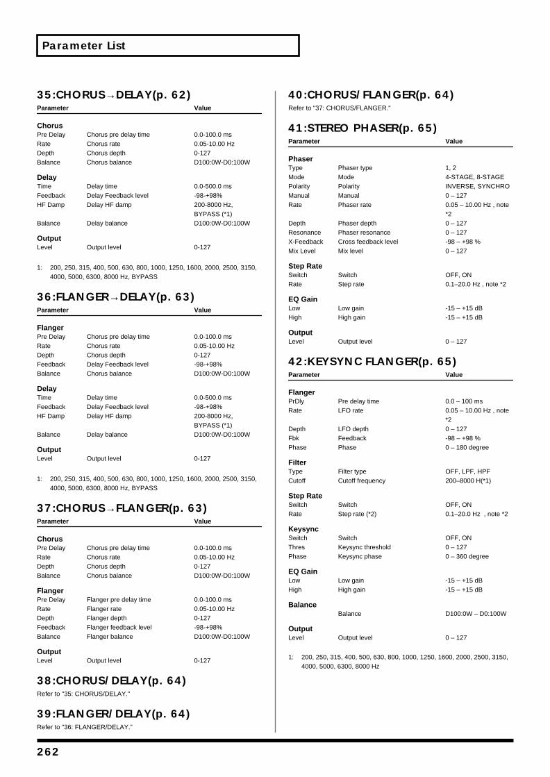
Parameter List
35:CHORUS→DELAY(p. 62)Parameter Value
ChorusPre Delay Chorus pre delay time 0.0-100.0 msRate Chorus rate 0.05-10.00 HzDepth Chorus depth 0-127Balance Chorus balance D100:0W-D0:100W
DelayTime Delay time 0.0-500.0 msFeedback Delay Feedback level -98-+98%HF Damp Delay HF damp 200-8000 Hz,
BYPASS (*1)Balance Delay balance D100:0W-D0:100W
OutputLevel Output level 0-127
1: 200, 250, 315, 400, 500, 630, 800, 1000, 1250, 1600, 2000, 2500, 3150, 4000, 5000, 6300, 8000 Hz, BYPASS
36:FLANGER→DELAY(p. 63)Parameter Value
FlangerPre Delay Chorus pre delay time 0.0-100.0 msRate Chorus rate 0.05-10.00 HzDepth Chorus depth 0-127Feedback Delay Feedback level -98-+98%Balance Chorus balance D100:0W-D0:100W
DelayTime Delay time 0.0-500.0 msFeedback Delay Feedback level -98-+98%HF Damp Delay HF damp 200-8000 Hz,
BYPASS (*1)Balance Delay balance D100:0W-D0:100W
OutputLevel Output level 0-127
1: 200, 250, 315, 400, 500, 630, 800, 1000, 1250, 1600, 2000, 2500, 3150, 4000, 5000, 6300, 8000 Hz, BYPASS
37:CHORUS→FLANGER(p. 63)Parameter Value
ChorusPre Delay Chorus pre delay time 0.0-100.0 msRate Chorus rate 0.05-10.00 HzDepth Chorus depth 0-127Balance Chorus balance D100:0W-D0:100W
FlangerPre Delay Flanger pre delay time 0.0-100.0 msRate Flanger rate 0.05-10.00 HzDepth Flanger depth 0-127Feedback Flanger feedback level -98-+98%Balance Flanger balance D100:0W-D0:100W
OutputLevel Output level 0-127
38:CHORUS/DELAY(p. 64)Refer to "35: CHORUS/DELAY."
39:FLANGER/DELAY(p. 64)Refer to "36: FLANGER/DELAY."
40:CHORUS/FLANGER(p. 64)Refer to "37: CHORUS/FLANGER."
41:STEREO PHASER(p. 65)Parameter Value
PhaserType Phaser type 1, 2 Mode Mode 4-STAGE, 8-STAGEPolarity Polarity INVERSE, SYNCHROManual Manual 0 – 127Rate Phaser rate 0.05 – 10.00 Hz , note
*2Depth Phaser depth 0 – 127Resonance Phaser resonance 0 – 127X-Feedback Cross feedback level -98 – +98 % Mix Level Mix level 0 – 127
Step RateSwitch Switch OFF, ONRate Step rate 0.1–20.0 Hz , note *2
EQ GainLow Low gain -15 – +15 dB High High gain -15 – +15 dB
OutputLevel Output level 0 – 127
42:KEYSYNC FLANGER(p. 65)Parameter Value
FlangerPrDly Pre delay time 0.0 – 100 ms Rate LFO rate 0.05 – 10.00 Hz , note
*2 Depth LFO depth 0 – 127Fbk Feedback -98 – +98 % Phase Phase 0 – 180 degree
FilterType Filter type OFF, LPF, HPFCutoff Cutoff frequency 200–8000 H(*1)
Step RateSwitch Switch OFF, ONRate Step rate (*2) 0.1–20.0 Hz , note *2
KeysyncSwitch Switch OFF, ONThres Keysync threshold 0 – 127Phase Keysync phase 0 – 360 degree
EQ GainLow Low gain -15 – +15 dB High High gain -15 – +15 dB
BalanceBalance D100:0W – D0:100W
OutputLevel Output level 0 – 127
1: 200, 250, 315, 400, 500, 630, 800, 1000, 1250, 1600, 2000, 2500, 3150, 4000, 5000, 6300, 8000 Hz
262
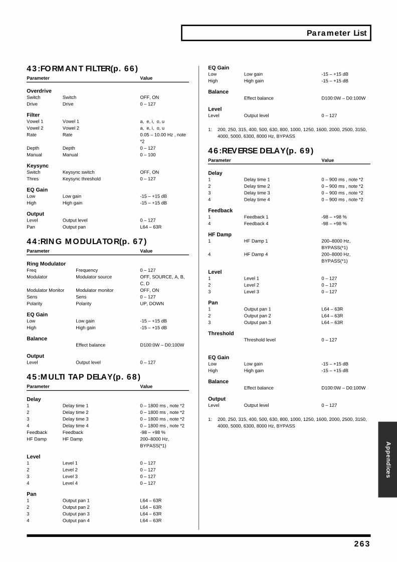
Parameter List
Appen
dices
43:FORMANT FILTER(p. 66)Parameter Value
OverdriveSwitch Switch OFF, ONDrive Drive 0 – 127
FilterVowel 1 Vowel 1 a, e, i, o, uVowel 2 Vowel 2 a, e, i, o, uRate Rate 0.05 – 10.00 Hz , note
*2Depth Depth 0 – 127Manual Manual 0 – 100
KeysyncSwitch Keysync switch OFF, ONThres Keysync threshold 0 – 127
EQ GainLow Low gain -15 – +15 dB High High gain -15 – +15 dB
OutputLevel Output level 0 – 127Pan Output pan L64 – 63R
44:RING MODULATOR(p. 67)Parameter Value
Ring ModulatorFreq Frequency 0 – 127 Modulator Modulator source OFF, SOURCE, A, B,
C, DModulator Monitor Modulator monitor OFF, ONSens Sens 0 – 127 Polarity Polarity UP, DOWN
EQ GainLow Low gain -15 – +15 dB High High gain -15 – +15 dB
BalanceEffect balance D100:0W – D0:100W
OutputLevel Output level 0 – 127
45:MULTI TAP DELAY(p. 68)Parameter Value
Delay1 Delay time 1 0 – 1800 ms , note *22 Delay time 2 0 – 1800 ms , note *23 Delay time 3 0 – 1800 ms , note *24 Delay time 4 0 – 1800 ms , note *2Feedback Feedback -98 – +98 %HF Damp HF Damp 200–8000 Hz,
BYPASS(*1)
Level1 Level 1 0 – 1272 Level 2 0 – 1273 Level 3 0 – 1274 Level 4 0 – 127
Pan1 Output pan 1 L64 – 63R2 Output pan 2 L64 – 63R3 Output pan 3 L64 – 63R4 Output pan 4 L64 – 63R
EQ GainLow Low gain -15 – +15 dB High High gain -15 – +15 dB
BalanceEffect balance D100:0W – D0:100W
LevelLevel Output level 0 – 127
1: 200, 250, 315, 400, 500, 630, 800, 1000, 1250, 1600, 2000, 2500, 3150, 4000, 5000, 6300, 8000 Hz, BYPASS
46:REVERSE DELAY(p. 69)Parameter Value
Delay1 Delay time 1 0 – 900 ms , note *22 Delay time 2 0 – 900 ms , note *23 Delay time 3 0 – 900 ms , note *24 Delay time 4 0 – 900 ms , note *2
Feedback1 Feedback 1 -98 – +98 % 4 Feedback 4 -98 – +98 %
HF Damp1 HF Damp 1 200–8000 Hz,
BYPASS(*1)4 HF Damp 4 200–8000 Hz,
BYPASS(*1)
Level1 Level 1 0 – 1272 Level 2 0 – 1273 Level 3 0 – 127
Pan1 Output pan 1 L64 – 63R2 Output pan 2 L64 – 63R3 Output pan 3 L64 – 63R
ThresholdThreshold level 0 – 127
EQ GainLow Low gain -15 – +15 dB High High gain -15 – +15 dB
BalanceEffect balance D100:0W – D0:100W
OutputLevel Output level 0 – 127
1: 200, 250, 315, 400, 500, 630, 800, 1000, 1250, 1600, 2000, 2500, 3150, 4000, 5000, 6300, 8000 Hz, BYPASS
263

Parameter List
47:SHUFFLE DELAY(p. 70)Parameter Value
DelayTime Delay time 0 – 1800 ms , note *2Shuffle Rate Shuffle rate 0 – 100 % Acceleration Acceleration 0 – 15Feedback Feedback -98 – +98 % HF Damp HF Damp 200–8000 Hz,
BYPASS(*1)
PanA Pan A L64 – 63RB Pan B L64 – 63R
BalanceLevel balance A100:0B – A0:100B
EQ GainLow Low gain -15 – +15 dB High High gain -15 – +15 dB
BalanceEffect balance D100:0E – D0:100W
OutputLevel Output level 0 – 127
1: 200, 250, 315, 400, 500, 630, 800, 1000, 1250, 1600, 2000, 2500, 3150, 4000, 5000, 6300, 8000 Hz, BYPASS
48:3D DELAY(p. 70)Parameter Value
DelayCenter Delay time center 0 – 1800 ms, note *2Left Delay time left 0 – 1800 ms, note *2Right Delay time right 0 – 1800 ms, note *2HF Damp HF Damp 200–8000 Hz,
BYPASS(*1)Feedback Feedback -98 – +98 %
Delay LevelCenter Level center 0 – 127Left Level left 0 – 127Right Level right 0 – 127
EQ GainLow Low gain -15 – +15 dB High High gain -15 – +15 dB
BalanceEffect balance D100:0E – D0:100W
OutputOut Output mode SPEAKER, PHONESLevel Output level 0 – 127
1: 200, 250, 315, 400, 500, 630, 800, 1000, 1250, 1600, 2000, 2500, 3150, 4000, 5000, 6300, 8000 Hz, BYPASS
49:3VOICE PITCH SHIFTER(p. 71)Parameter Value
Pch Coarse1-3 Coarse pitch 1-3 -24 – +12
Pch Fine1-3 Fine pitch 1-3 -100 – +100 [cent]
Pitch ShiftMode Pitch shifter mode 1, 2, 3, 4, 5
Fbk1-3 Feedback level 1-3 -98 – +98 %
Pre Delay 1-3 Pre Delay time 1-3 0.0 – 500 [ms]
Balance
Effect balance D100:0E – D0:100W
Level1-3 Level 1-3 0 – 127
Pan1-3 Output pan 1-3 L64 – 63R
OutputOutput level 0 – 127
50:LOFI COMPRESS(p. 72)Parameter Value
Lo-FiType LOFI type 1 – 9
Pre FilterType Pre Filter type 1 – 6
Post Filter 1Type Post Filter 1 type 1 – 6
Post Filter 2Type Post Filter 2 type OFF, LPF, HPF:(*1)Cutoff Cutoff Frequency (*1)
EQ GainLow Low gain -15 – +15 dB High High gain -15 – +15 dB
BalanceEffect balance D100:0E – D0:100W
OutputLevel Output level 0 – 127Pan Output pan L64 – 63R
1: Post Filter cutoff frequency:200, 250, 315, 400, 500, 630, 800, 1000, 1250, 1600, 2000, 2500, 3150, 4000, 5000, 6300, 8000 Hz
264
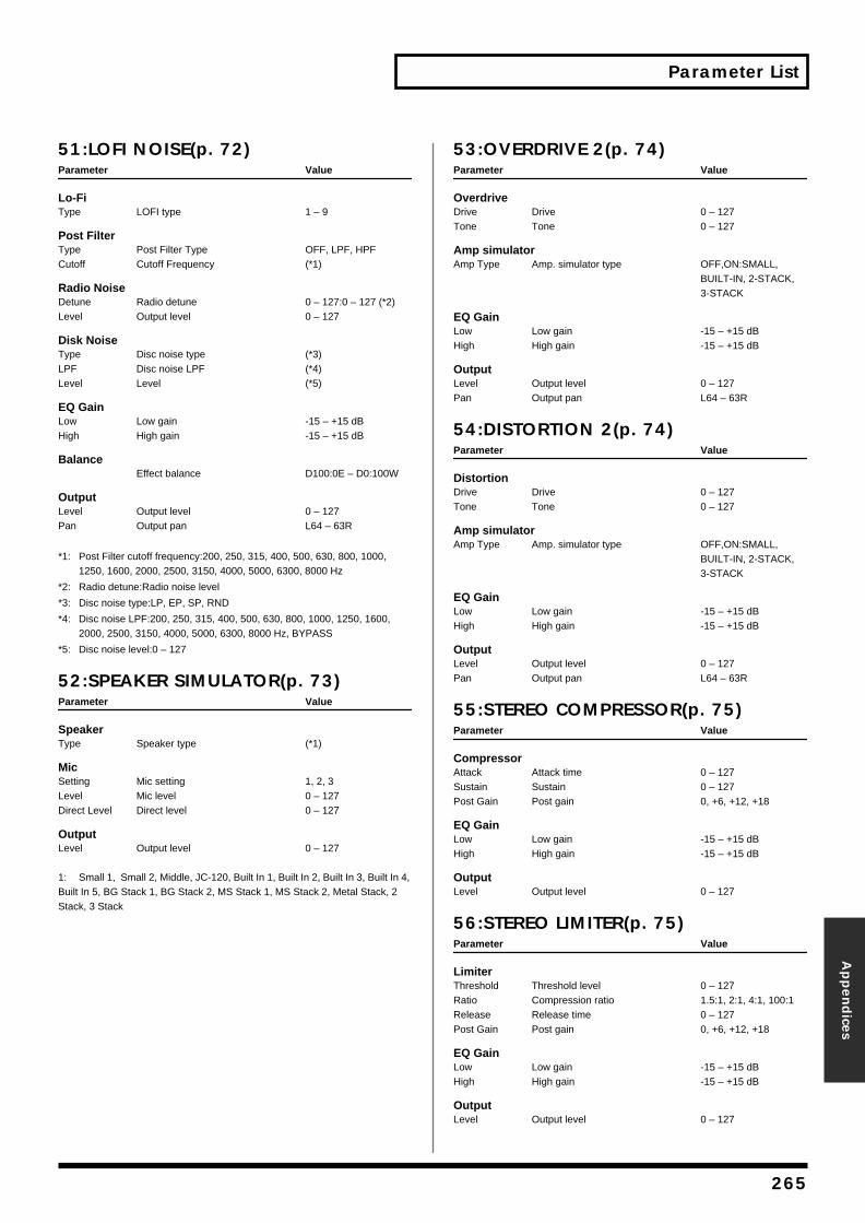
Parameter List
Appen
dices
51:LOFI NOISE(p. 72)Parameter Value
Lo-FiType LOFI type 1 – 9
Post FilterType Post Filter Type OFF, LPF, HPFCutoff Cutoff Frequency (*1)
Radio NoiseDetune Radio detune 0 – 127:0 – 127 (*2)Level Output level 0 – 127
Disk NoiseType Disc noise type (*3)LPF Disc noise LPF (*4)Level Level (*5)
EQ GainLow Low gain -15 – +15 dB High High gain -15 – +15 dB
BalanceEffect balance D100:0E – D0:100W
OutputLevel Output level 0 – 127Pan Output pan L64 – 63R
*1: Post Filter cutoff frequency:200, 250, 315, 400, 500, 630, 800, 1000, 1250, 1600, 2000, 2500, 3150, 4000, 5000, 6300, 8000 Hz
*2: Radio detune:Radio noise level
*3: Disc noise type:LP, EP, SP, RND
*4: Disc noise LPF:200, 250, 315, 400, 500, 630, 800, 1000, 1250, 1600, 2000, 2500, 3150, 4000, 5000, 6300, 8000 Hz, BYPASS
*5: Disc noise level:0 – 127
52:SPEAKER SIMULATOR(p. 73)Parameter Value
SpeakerType Speaker type (*1)
MicSetting Mic setting 1, 2, 3Level Mic level 0 – 127Direct Level Direct level 0 – 127
OutputLevel Output level 0 – 127
1: Small 1, Small 2, Middle, JC-120, Built In 1, Built In 2, Built In 3, Built In 4, Built In 5, BG Stack 1, BG Stack 2, MS Stack 1, MS Stack 2, Metal Stack, 2 Stack, 3 Stack
53:OVERDRIVE 2(p. 74)Parameter Value
OverdriveDrive Drive 0 – 127Tone Tone 0 – 127
Amp simulatorAmp Type Amp. simulator type OFF,ON:SMALL,
BUILT-IN, 2-STACK, 3-STACK
EQ GainLow Low gain -15 – +15 dB High High gain -15 – +15 dB
OutputLevel Output level 0 – 127Pan Output pan L64 – 63R
54:DISTORTION 2(p. 74)Parameter Value
DistortionDrive Drive 0 – 127Tone Tone 0 – 127
Amp simulatorAmp Type Amp. simulator type OFF,ON:SMALL,
BUILT-IN, 2-STACK, 3-STACK
EQ GainLow Low gain -15 – +15 dB High High gain -15 – +15 dB
OutputLevel Output level 0 – 127Pan Output pan L64 – 63R
55:STEREO COMPRESSOR(p. 75)Parameter Value
CompressorAttack Attack time 0 – 127Sustain Sustain 0 – 127Post Gain Post gain 0, +6, +12, +18
EQ GainLow Low gain -15 – +15 dB High High gain -15 – +15 dB
OutputLevel Output level 0 – 127
56:STEREO LIMITER(p. 75)Parameter Value
LimiterThreshold Threshold level 0 – 127Ratio Compression ratio 1.5:1, 2:1, 4:1, 100:1Release Release time 0 – 127Post Gain Post gain 0, +6, +12, +18
EQ GainLow Low gain -15 – +15 dB High High gain -15 – +15 dB
OutputLevel Output level 0 – 127
265
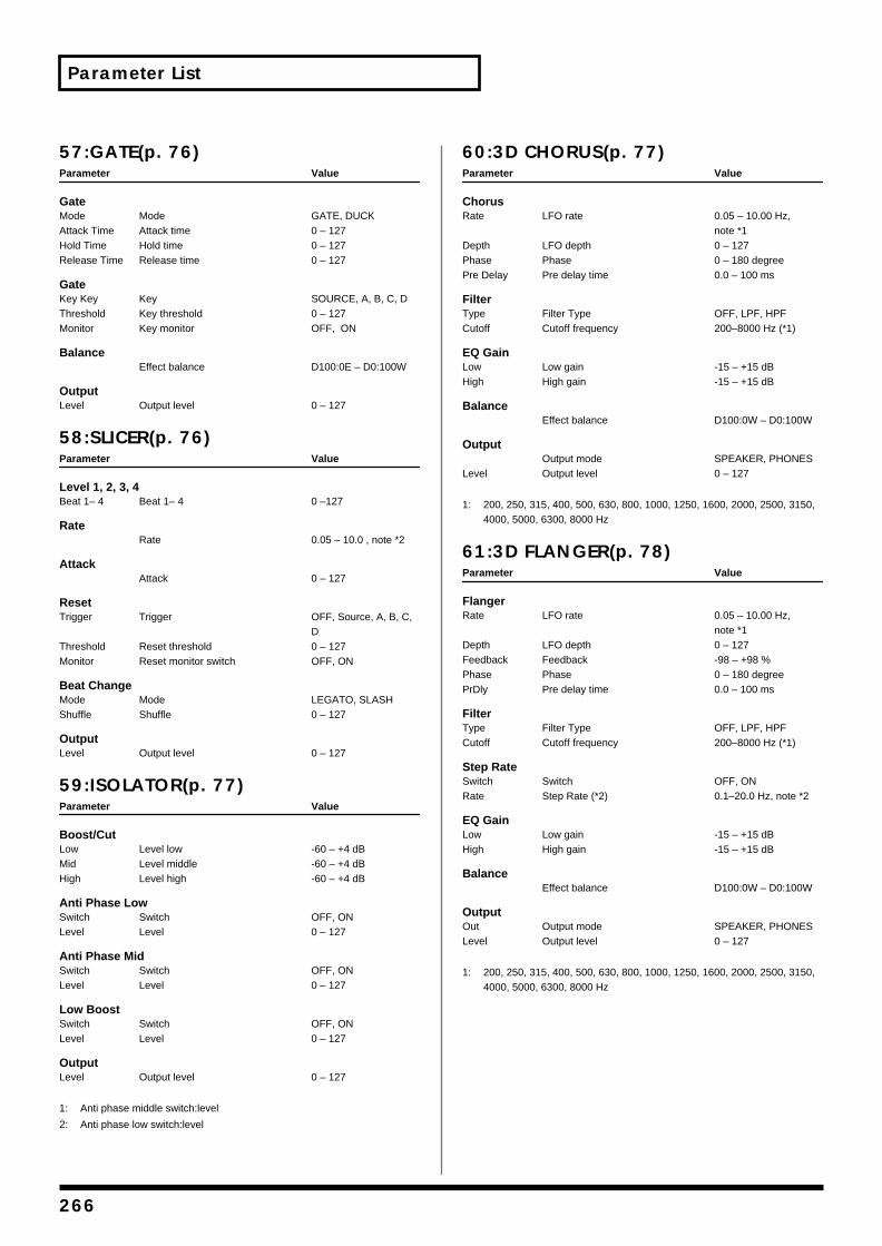
Parameter List
57:GATE(p. 76)Parameter Value
GateMode Mode GATE, DUCKAttack Time Attack time 0 – 127Hold Time Hold time 0 – 127Release Time Release time 0 – 127
GateKey Key Key SOURCE, A, B, C, DThreshold Key threshold 0 – 127Monitor Key monitor OFF, ON
BalanceEffect balance D100:0E – D0:100W
OutputLevel Output level 0 – 127
58:SLICER(p. 76)Parameter Value
Level 1, 2, 3, 4Beat 1– 4 Beat 1– 4 0 –127
RateRate 0.05 – 10.0 , note *2
AttackAttack 0 – 127
ResetTrigger Trigger OFF, Source, A, B, C,
DThreshold Reset threshold 0 – 127Monitor Reset monitor switch OFF, ON
Beat ChangeMode Mode LEGATO, SLASHShuffle Shuffle 0 – 127
OutputLevel Output level 0 – 127
59:ISOLATOR(p. 77)Parameter Value
Boost/CutLow Level low -60 – +4 dBMid Level middle -60 – +4 dB High Level high -60 – +4 dB
Anti Phase LowSwitch Switch OFF, ONLevel Level 0 – 127
Anti Phase MidSwitch Switch OFF, ONLevel Level 0 – 127
Low BoostSwitch Switch OFF, ONLevel Level 0 – 127
OutputLevel Output level 0 – 127
1: Anti phase middle switch:level
2: Anti phase low switch:level
60:3D CHORUS(p. 77)Parameter Value
ChorusRate LFO rate 0.05 – 10.00 Hz,
note *1Depth LFO depth 0 – 127Phase Phase 0 – 180 degreePre Delay Pre delay time 0.0 – 100 ms
FilterType Filter Type OFF, LPF, HPFCutoff Cutoff frequency 200–8000 Hz (*1)
EQ GainLow Low gain -15 – +15 dB High High gain -15 – +15 dB
BalanceEffect balance D100:0W – D0:100W
OutputOutput mode SPEAKER, PHONES
Level Output level 0 – 127
1: 200, 250, 315, 400, 500, 630, 800, 1000, 1250, 1600, 2000, 2500, 3150, 4000, 5000, 6300, 8000 Hz
61:3D FLANGER(p. 78)Parameter Value
FlangerRate LFO rate 0.05 – 10.00 Hz,
note *1Depth LFO depth 0 – 127Feedback Feedback -98 – +98 %Phase Phase 0 – 180 degreePrDly Pre delay time 0.0 – 100 ms
FilterType Filter Type OFF, LPF, HPFCutoff Cutoff frequency 200–8000 Hz (*1)
Step RateSwitch Switch OFF, ONRate Step Rate (*2) 0.1–20.0 Hz, note *2
EQ GainLow Low gain -15 – +15 dB High High gain -15 – +15 dB
BalanceEffect balance D100:0W – D0:100W
OutputOut Output mode SPEAKER, PHONESLevel Output level 0 – 127
1: 200, 250, 315, 400, 500, 630, 800, 1000, 1250, 1600, 2000, 2500, 3150, 4000, 5000, 6300, 8000 Hz
266
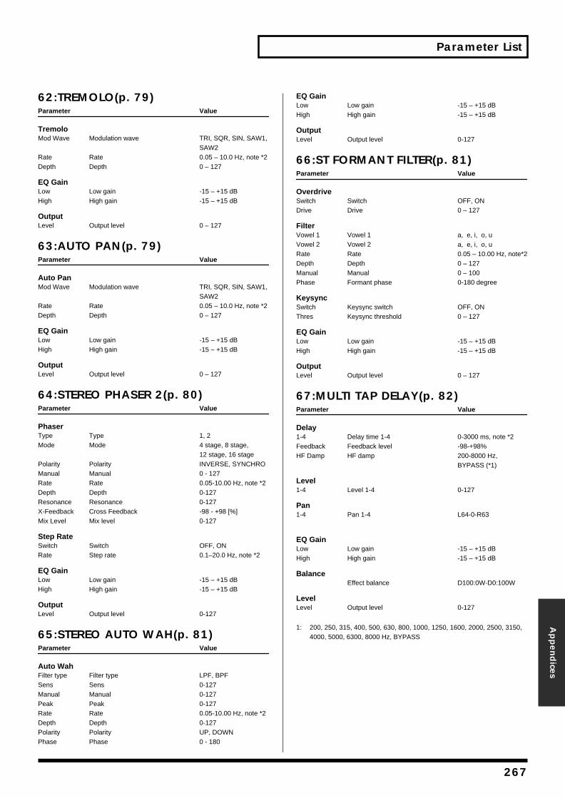
Parameter List
Appen
dices
62:TREMOLO(p. 79)Parameter Value
TremoloMod Wave Modulation wave TRI, SQR, SIN, SAW1,
SAW2Rate Rate 0.05 – 10.0 Hz, note *2Depth Depth 0 – 127
EQ GainLow Low gain -15 – +15 dB High High gain -15 – +15 dB
OutputLevel Output level 0 – 127
63:AUTO PAN(p. 79)Parameter Value
Auto PanMod Wave Modulation wave TRI, SQR, SIN, SAW1,
SAW2Rate Rate 0.05 – 10.0 Hz, note *2Depth Depth 0 – 127
EQ GainLow Low gain -15 – +15 dB High High gain -15 – +15 dB
OutputLevel Output level 0 – 127
64:STEREO PHASER 2(p. 80)Parameter Value
PhaserType Type 1, 2Mode Mode 4 stage, 8 stage,
12 stage, 16 stagePolarity Polarity INVERSE, SYNCHROManual Manual 0 - 127Rate Rate 0.05-10.00 Hz, note *2Depth Depth 0-127Resonance Resonance 0-127X-Feedback Cross Feedback -98 - +98 [%]Mix Level Mix level 0-127
Step RateSwitch Switch OFF, ONRate Step rate 0.1–20.0 Hz, note *2
EQ GainLow Low gain -15 – +15 dB High High gain -15 – +15 dB
OutputLevel Output level 0-127
65:STEREO AUTO WAH(p. 81)Parameter Value
Auto WahFilter type Filter type LPF, BPFSens Sens 0-127Manual Manual 0-127Peak Peak 0-127Rate Rate 0.05-10.00 Hz, note *2Depth Depth 0-127Polarity Polarity UP, DOWNPhase Phase 0 - 180
EQ GainLow Low gain -15 – +15 dB High High gain -15 – +15 dB
OutputLevel Output level 0-127
66:ST FORMANT FILTER(p. 81)Parameter Value
OverdriveSwitch Switch OFF, ONDrive Drive 0 – 127
FilterVowel 1 Vowel 1 a, e, i, o, uVowel 2 Vowel 2 a, e, i, o, uRate Rate 0.05 – 10.00 Hz, note*2Depth Depth 0 – 127Manual Manual 0 – 100Phase Formant phase 0-180 degree
KeysyncSwitch Keysync switch OFF, ONThres Keysync threshold 0 – 127
EQ GainLow Low gain -15 – +15 dB High High gain -15 – +15 dB
OutputLevel Output level 0 – 127
67:MULTI TAP DELAY(p. 82)Parameter Value
Delay1-4 Delay time 1-4 0-3000 ms, note *2Feedback Feedback level -98-+98%HF Damp HF damp 200-8000 Hz,
BYPASS (*1)
Level1-4 Level 1-4 0-127
Pan1-4 Pan 1-4 L64-0-R63
EQ GainLow Low gain -15 – +15 dB High High gain -15 – +15 dB
BalanceEffect balance D100:0W-D0:100W
LevelLevel Output level 0-127
1: 200, 250, 315, 400, 500, 630, 800, 1000, 1250, 1600, 2000, 2500, 3150, 4000, 5000, 6300, 8000 Hz, BYPASS
267

Parameter List
68:REVERSE DELAY 2(p. 82)Parameter Value
Delay1-4 Delay time 1-4 0-1500 ms, note *2
Feedback1, 4 Feedback level 1, 4 -98-+98%
HF Damp1, 4 HF damp 1, 4 200-8000 Hz, BYPASS
(*1)
Level1-3 Level 1-3 0-127
Pan1-3 Pan 1-3 L64-0-R63
ThresholdValue Value 0-127
EQ GainLow Low gain -15 – +15 dB High High gain -15 – +15 dB
BalanceEffect balance D100:0W-D0:100W
OutputLevel Output level 0-127
1: 200, 250, 315, 400, 500, 630, 800, 1000, 1250, 1600, 2000, 2500, 3150, 4000, 5000, 6300, 8000 Hz, BYPASS
69:SHUFFLE DELAY 2(p. 83)Parameter Value
DelayTime Delay time 0-3000 ms, note *2Shuffle Rate Shuffle Rate 0-100%Acceleration Acceleration 0-15Feedback Feedback level -98-+98%HF Damp HF damp 200-8000 Hz,
BYPASS (*1)
Delay PanA, B Pan A, B L64-0-R63
BalanceLevel Balance A100:0B-A0:100B
EQ GainLow Low gain -15 – +15 dB High High gain -15 – +15 dB
BalanceEffect balance D100:0W-D0:100W
OutputLevel Output level 0-127
1: 200, 250, 315, 400, 500, 630, 800, 1000, 1250, 1600, 2000, 2500, 3150, 4000, 5000, 6300, 8000 Hz, BYPASS
70:3D DELAY 2(p. 83)Parameter Value
DelayCenter Delay time center 0-3000 ms, note *2Left Delay time left 0-3000 ms, note *2Right Delay time right 0-3000 ms, note *2HF Damp HF damp 200-8000 Hz,
BYPASS (*1)Feedback Feedback level -98-+98%
Delay LevelCenter Center level 0-127Left Left level 0-127Right Right level 0-127
EQ GainLow Low gain -15-+15 dBHigh High gain -15-+15 dB
BalanceEffect balance D100:0W-D0:100W
LevelOut Output mode SPEAKER, PHONESLevel Output level 0-127
71:ROTARY 2(p. 85)Parameter Value
RotarySpeed Speed SLOW, FASTBrake Brake OFF,ON
SpreadValue Value 0-127
WooferSlow Woofer slow rate 0.05-10.00 Hz, note *2Fast Woofer fast rate 0.05-10.00 Hz, note *2Level Woofer level 0-127Trans Up Woofer transition up 0-127Trans Down Woofer transition down 0-127
TweeterSlow Tweeter slow rate 0.05-10.00 Hz, note *2Fast Tweeter fast rate 0.05-10.00 Hz, note *2Level Tweeter level 0-127Trans Up Tweeter transition up 0-127Trans Down Tweeter transition down 0-127
EQ GainLow Low gain -15-+15 dBHigh High gain -15-+15 dB
OutputLevel Output level 0-127
268
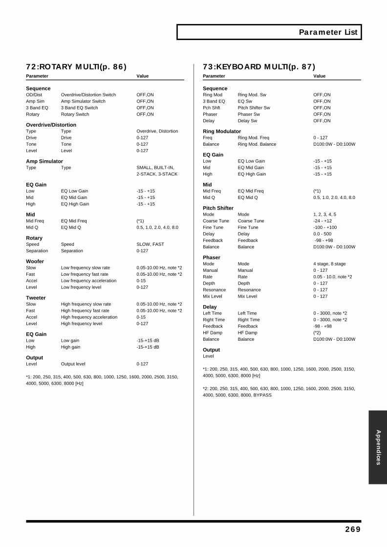
Parameter List
Appen
dices
72:ROTARY MULTI(p. 86)Parameter Value
SequenceOD/Dist Overdrive/Distortion Switch OFF,ONAmp Sim Amp Simulator Switch OFF,ON3 Band EQ 3 Band EQ Switch OFF,ONRotary Rotary Switch OFF,ON
Overdrive/DistortionType Type Overdrive, DistortionDrive Drive 0-127Tone Tone 0-127Level Level 0-127
Amp SimulatorType Type SMALL, BUILT-IN,
2-STACK, 3-STACK
EQ GainLow EQ Low Gain -15 - +15Mid EQ Mid Gain -15 - +15High EQ High Gain -15 - +15
MidMid Freq EQ Mid Freq (*1)Mid Q EQ Mid Q 0.5, 1.0, 2.0, 4.0, 8.0
RotarySpeed Speed SLOW, FASTSeparation Separation 0-127
WooferSlow Low frequency slow rate 0.05-10.00 Hz, note *2Fast Low frequency fast rate 0.05-10.00 Hz, note *2Accel Low frequency acceleration 0-15Level Low frequency level 0-127
TweeterSlow High frequency slow rate 0.05-10.00 Hz, note *2Fast High frequency fast rate 0.05-10.00 Hz, note *2Accel High frequency acceleration 0-15Level High frequency level 0-127
EQ GainLow Low gain -15-+15 dBHigh High gain -15-+15 dB
OutputLevel Output level 0-127
*1: 200, 250, 315, 400, 500, 630, 800, 1000, 1250, 1600, 2000, 2500, 3150, 4000, 5000, 6300, 8000 [Hz]
73:KEYBOARD MULTI(p. 87)Parameter Value
SequenceRing Mod Ring Mod. Sw OFF,ON3 Band EQ EQ Sw OFF,ONPch Shft Pitch Shifter Sw OFF,ONPhaser Phaser Sw OFF,ONDelay Delay Sw OFF,ON
Ring ModulatorFreq Ring Mod. Freq 0 - 127Balance Ring Mod. Balance D100:0W - D0:100W
EQ GainLow EQ Low Gain -15 - +15Mid EQ Mid Gain -15 - +15High EQ High Gain -15 - +15
MidMid Freq EQ Mid Freq (*1)Mid Q EQ Mid Q 0.5, 1.0, 2.0, 4.0, 8.0
Pitch ShifterMode Mode 1, 2, 3, 4, 5Coarse Tune Coarse Tune -24 - +12Fine Tune Fine Tune -100 - +100Delay Delay 0.0 - 500Feedback Feedback -98 - +98Balance Balance D100:0W - D0:100W
PhaserMode Mode 4 stage, 8 stageManual Manual 0 - 127Rate Rate 0.05 - 10.0, note *2Depth Depth 0 - 127Resonance Resonance 0 - 127Mix Level Mix Level 0 - 127
DelayLeft Time Left Time 0 - 3000, note *2Right Time Right Time 0 - 3000, note *2Feedback Feedback -98 - +98HF Damp HF Damp (*2)Balance Balance D100:0W - D0:100W
OutputLevel
*1: 200, 250, 315, 400, 500, 630, 800, 1000, 1250, 1600, 2000, 2500, 3150, 4000, 5000, 6300, 8000 [Hz]
*2: 200, 250, 315, 400, 500, 630, 800, 1000, 1250, 1600, 2000, 2500, 3150, 4000, 5000, 6300, 8000, BYPASS
269
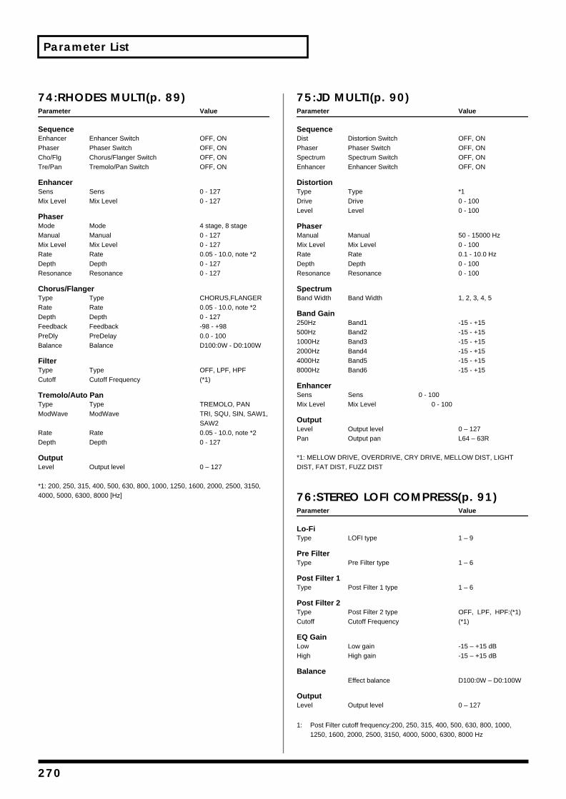
Parameter List
74:RHODES MULTI(p. 89)Parameter Value
SequenceEnhancer Enhancer Switch OFF, ONPhaser Phaser Switch OFF, ONCho/Flg Chorus/Flanger Switch OFF, ONTre/Pan Tremolo/Pan Switch OFF, ON
EnhancerSens Sens 0 - 127Mix Level Mix Level 0 - 127
PhaserMode Mode 4 stage, 8 stageManual Manual 0 - 127Mix Level Mix Level 0 - 127Rate Rate 0.05 - 10.0, note *2Depth Depth 0 - 127Resonance Resonance 0 - 127
Chorus/FlangerType Type CHORUS,FLANGERRate Rate 0.05 - 10.0, note *2Depth Depth 0 - 127Feedback Feedback -98 - +98PreDly PreDelay 0.0 - 100Balance Balance D100:0W - D0:100W
FilterType Type OFF, LPF, HPFCutoff Cutoff Frequency (*1)
Tremolo/Auto PanType Type TREMOLO, PANModWave ModWave TRI, SQU, SIN, SAW1,
SAW2Rate Rate 0.05 - 10.0, note *2Depth Depth 0 - 127
OutputLevel Output level 0 – 127
*1: 200, 250, 315, 400, 500, 630, 800, 1000, 1250, 1600, 2000, 2500, 3150, 4000, 5000, 6300, 8000 [Hz]
75:JD MULTI(p. 90)Parameter Value
SequenceDist Distortion Switch OFF, ONPhaser Phaser Switch OFF, ONSpectrum Spectrum Switch OFF, ONEnhancer Enhancer Switch OFF, ON
DistortionType Type *1Drive Drive 0 - 100Level Level 0 - 100
PhaserManual Manual 50 - 15000 HzMix Level Mix Level 0 - 100Rate Rate 0.1 - 10.0 HzDepth Depth 0 - 100Resonance Resonance 0 - 100
SpectrumBand Width Band Width 1, 2, 3, 4, 5
Band Gain250Hz Band1 -15 - +15500Hz Band2 -15 - +151000Hz Band3 -15 - +152000Hz Band4 -15 - +154000Hz Band5 -15 - +158000Hz Band6 -15 - +15
EnhancerSens Sens 0 - 100Mix Level Mix Level 0 - 100
OutputLevel Output level 0 – 127Pan Output pan L64 – 63R
*1: MELLOW DRIVE, OVERDRIVE, CRY DRIVE, MELLOW DIST, LIGHT DIST, FAT DIST, FUZZ DIST
76:STEREO LOFI COMPRESS(p. 91)Parameter Value
Lo-FiType LOFI type 1 – 9
Pre FilterType Pre Filter type 1 – 6
Post Filter 1Type Post Filter 1 type 1 – 6
Post Filter 2Type Post Filter 2 type OFF, LPF, HPF:(*1)Cutoff Cutoff Frequency (*1)
EQ GainLow Low gain -15 – +15 dB High High gain -15 – +15 dB
BalanceEffect balance D100:0W – D0:100W
OutputLevel Output level 0 – 127
1: Post Filter cutoff frequency:200, 250, 315, 400, 500, 630, 800, 1000, 1250, 1600, 2000, 2500, 3150, 4000, 5000, 6300, 8000 Hz
270
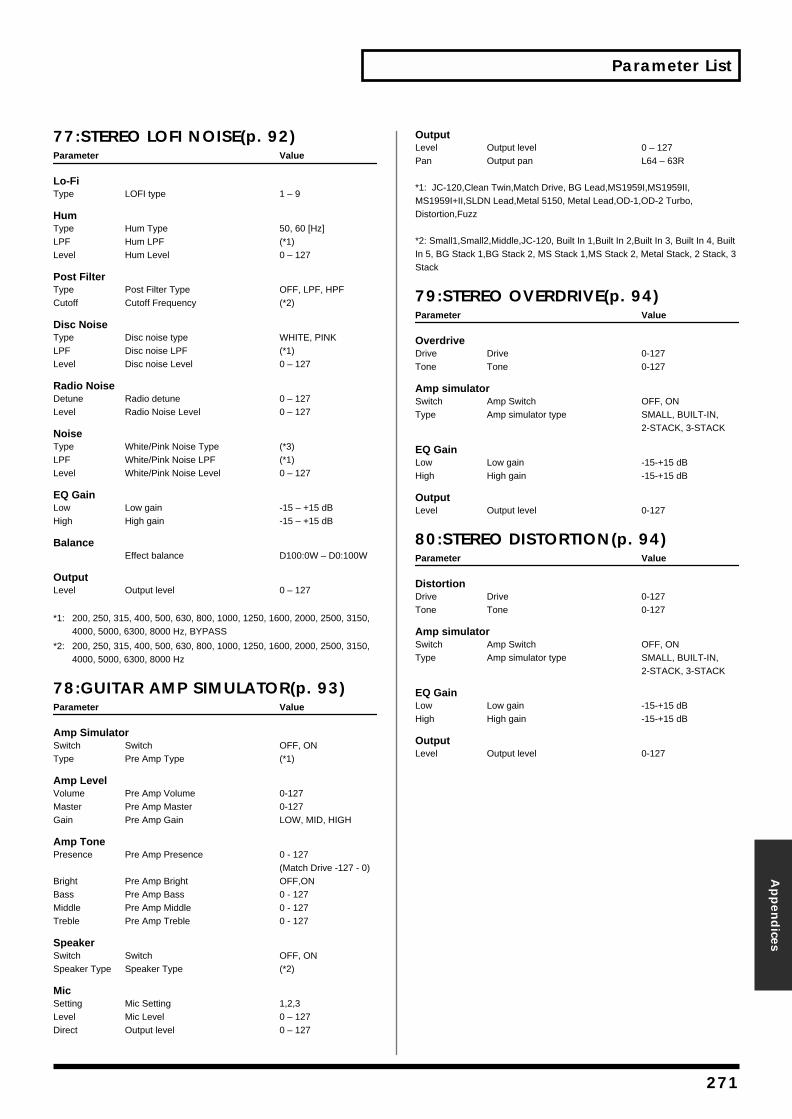
Parameter List
Appen
dices
77:STEREO LOFI NOISE(p. 92)Parameter Value
Lo-FiType LOFI type 1 – 9
HumType Hum Type 50, 60 [Hz]LPF Hum LPF (*1)Level Hum Level 0 – 127
Post FilterType Post Filter Type OFF, LPF, HPFCutoff Cutoff Frequency (*2)
Disc NoiseType Disc noise type WHITE, PINKLPF Disc noise LPF (*1)Level Disc noise Level 0 – 127
Radio NoiseDetune Radio detune 0 – 127Level Radio Noise Level 0 – 127
NoiseType White/Pink Noise Type (*3)LPF White/Pink Noise LPF (*1)Level White/Pink Noise Level 0 – 127
EQ GainLow Low gain -15 – +15 dB High High gain -15 – +15 dB
BalanceEffect balance D100:0W – D0:100W
OutputLevel Output level 0 – 127
*1: 200, 250, 315, 400, 500, 630, 800, 1000, 1250, 1600, 2000, 2500, 3150, 4000, 5000, 6300, 8000 Hz, BYPASS
*2: 200, 250, 315, 400, 500, 630, 800, 1000, 1250, 1600, 2000, 2500, 3150, 4000, 5000, 6300, 8000 Hz
78:GUITAR AMP SIMULATOR(p. 93)Parameter Value
Amp SimulatorSwitch Switch OFF, ONType Pre Amp Type (*1)
Amp LevelVolume Pre Amp Volume 0-127Master Pre Amp Master 0-127Gain Pre Amp Gain LOW, MID, HIGH
Amp TonePresence Pre Amp Presence 0 - 127
(Match Drive -127 - 0)Bright Pre Amp Bright OFF,ONBass Pre Amp Bass 0 - 127Middle Pre Amp Middle 0 - 127Treble Pre Amp Treble 0 - 127
SpeakerSwitch Switch OFF, ONSpeaker Type Speaker Type (*2)
MicSetting Mic Setting 1,2,3Level Mic Level 0 – 127Direct Output level 0 – 127
OutputLevel Output level 0 – 127Pan Output pan L64 – 63R
*1: JC-120,Clean Twin,Match Drive, BG Lead,MS1959I,MS1959II, MS1959I+II,SLDN Lead,Metal 5150, Metal Lead,OD-1,OD-2 Turbo, Distortion,Fuzz
*2: Small1,Small2,Middle,JC-120, Built In 1,Built In 2,Built In 3, Built In 4, Built In 5, BG Stack 1,BG Stack 2, MS Stack 1,MS Stack 2, Metal Stack, 2 Stack, 3 Stack
79:STEREO OVERDRIVE(p. 94)Parameter Value
OverdriveDrive Drive 0-127Tone Tone 0-127
Amp simulatorSwitch Amp Switch OFF, ONType Amp simulator type SMALL, BUILT-IN,
2-STACK, 3-STACK
EQ GainLow Low gain -15-+15 dBHigh High gain -15-+15 dB
OutputLevel Output level 0-127
80:STEREO DISTORTION(p. 94)Parameter Value
DistortionDrive Drive 0-127Tone Tone 0-127
Amp simulatorSwitch Amp Switch OFF, ONType Amp simulator type SMALL, BUILT-IN,
2-STACK, 3-STACK
EQ GainLow Low gain -15-+15 dBHigh High gain -15-+15 dB
OutputLevel Output level 0-127
271
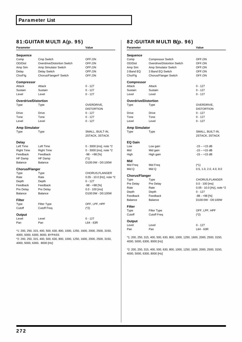
Parameter List
81:GUITAR MULTI A(p. 95)Parameter Value
SequenceComp Cmp Switch OFF,ONOD/Dist Overdrive/Distortion Switch OFF,ONAmp Sim Amp Simulator Switch OFF,ONDelay Delay Switch OFF,ONCho/Flg Chorus/FlangerF Switch OFF,ON
CompressorAttack Attack 0 - 127Sustain Sustain 0 - 127Level Level 0 - 127
Overdrive/DistortionType Type OVERDRIVE,
DISTORTIONDrive Drive 0 - 127Tone Tone 0 - 127Level Level 0 - 127
Amp SimulatorType Type SMALL, BUILT-IN,
2STACK, 3STACK
DelayLeft Time Left Time 0 - 3000 [ms], note *2Right Time Right Time 0 - 3000 [ms], note *2Feedback Feedback -98 - +98 [%]HF Damp HF Damp (*1)Balance Balance D100:0W - D0:100W
Chorus/FlangerType Type CHORUS,FLANGERRate Rate 0.05 - 10.0 [Hz], note *2Depth Depth 0 - 127Feedback Feedback -98 - +98 [%]Pre Delay Pre Delay 0.0 - 100 [ms]Balance Balance D100:0W - D0:100W
FilterType Filter Type OFF, LPF, HPFCutoff Cutoff Freq (*2)
OutputLevel Level 0 - 127Pan Pan L64 - 63R
*1: 200, 250, 315, 400, 500, 630, 800, 1000, 1250, 1600, 2000, 2500, 3150, 4000, 5000, 6300, 8000, BYPASS*2: 200, 250, 315, 400, 500, 630, 800, 1000, 1250, 1600, 2000, 2500, 3150, 4000, 5000, 6300, 8000 [Hz]
82:GUITAR MULTI B(p. 96)Parameter Value
SequenceComp Compressor Switch OFF,ONOD/Dist Overdrive/Distortion Switch OFF,ONAmp Sim Amp Simulator Switch OFF,ON3 Band EQ 3 Band EQ Switch OFF,ONCho/Flg Chorus/Flanger Switch OFF,ON
CompressorAttack Attack 0 - 127Sustain Sustain 0 - 127Level Level 0 - 127
Overdrive/DistortionType Type OVERDRIVE,
DISTORTIONDrive Drive 0 - 127Tone Tone 0 - 127Level Level 0 - 127
Amp SimulatorType Type SMALL, BUILT-IN,
2STACK, 3STACK
EQ GainLow Low gain -15 – +15 dB Mid Mid gain -15 – +15 dB High High gain -15 – +15 dB
MidMid Freq Mid Freq (*1)Mid Q Mid Q 0.5, 1.0, 2.0, 4.0, 8.0
Chorus/FlangerType Type CHORUS,FLANGERPre Delay Pre Delay 0.0 - 100 [ms]Rate Rate 0.05 - 10.0 [Hz], note *2Depth Depth 0 - 127Feedback Feedback -98 - +98 [%]Balance Balance D100:0W - D0:100W
FilterType Filter Type OFF, LPF, HPFCutoff Cutoff Freq (*2)
OutputLevel Level 0 - 127Pan Pan L64 - 63R
*1: 200, 250, 315, 400, 500, 630, 800, 1000, 1250, 1600, 2000, 2500, 3150, 4000, 5000, 6300, 8000 [Hz]
*2: 200, 250, 315, 400, 500, 630, 800, 1000, 1250, 1600, 2000, 2500, 3150, 4000, 5000, 6300, 8000 [Hz]
272
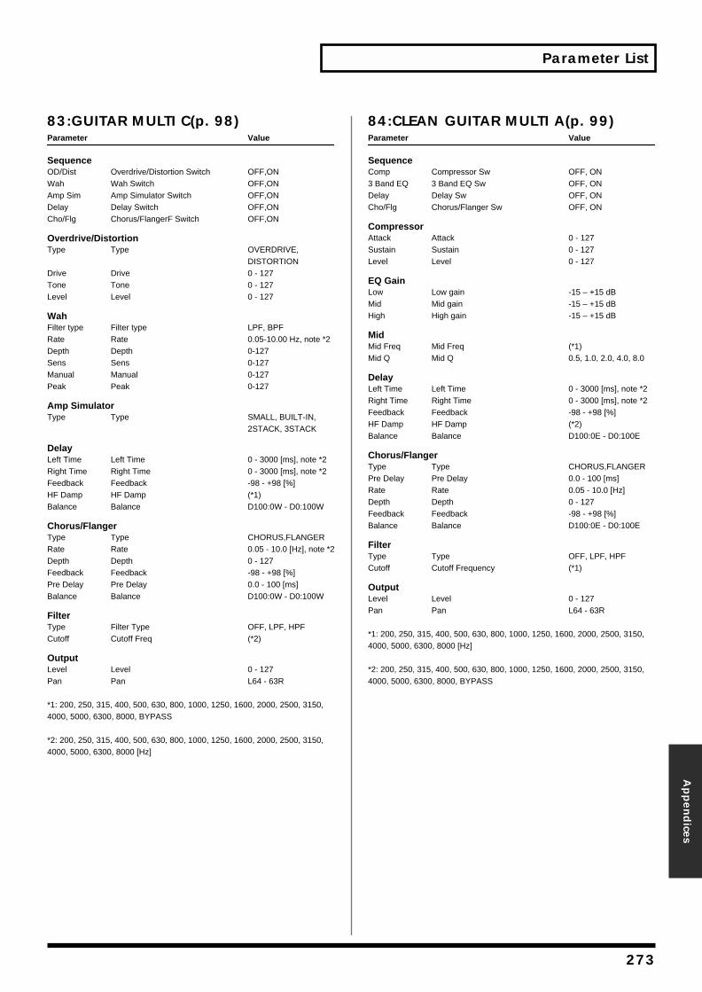
Parameter List
Appen
dices
83:GUITAR MULTI C(p. 98)Parameter Value
SequenceOD/Dist Overdrive/Distortion Switch OFF,ONWah Wah Switch OFF,ONAmp Sim Amp Simulator Switch OFF,ONDelay Delay Switch OFF,ONCho/Flg Chorus/FlangerF Switch OFF,ON
Overdrive/DistortionType Type OVERDRIVE,
DISTORTIONDrive Drive 0 - 127Tone Tone 0 - 127Level Level 0 - 127
WahFilter type Filter type LPF, BPFRate Rate 0.05-10.00 Hz, note *2Depth Depth 0-127Sens Sens 0-127Manual Manual 0-127Peak Peak 0-127
Amp SimulatorType Type SMALL, BUILT-IN,
2STACK, 3STACK
DelayLeft Time Left Time 0 - 3000 [ms], note *2Right Time Right Time 0 - 3000 [ms], note *2Feedback Feedback -98 - +98 [%]HF Damp HF Damp (*1)Balance Balance D100:0W - D0:100W
Chorus/FlangerType Type CHORUS,FLANGERRate Rate 0.05 - 10.0 [Hz], note *2Depth Depth 0 - 127Feedback Feedback -98 - +98 [%]Pre Delay Pre Delay 0.0 - 100 [ms]Balance Balance D100:0W - D0:100W
FilterType Filter Type OFF, LPF, HPFCutoff Cutoff Freq (*2)
OutputLevel Level 0 - 127Pan Pan L64 - 63R
*1: 200, 250, 315, 400, 500, 630, 800, 1000, 1250, 1600, 2000, 2500, 3150, 4000, 5000, 6300, 8000, BYPASS
*2: 200, 250, 315, 400, 500, 630, 800, 1000, 1250, 1600, 2000, 2500, 3150, 4000, 5000, 6300, 8000 [Hz]
84:CLEAN GUITAR MULTI A(p. 99)Parameter Value
SequenceComp Compressor Sw OFF, ON3 Band EQ 3 Band EQ Sw OFF, ONDelay Delay Sw OFF, ONCho/Flg Chorus/Flanger Sw OFF, ON
CompressorAttack Attack 0 - 127Sustain Sustain 0 - 127Level Level 0 - 127
EQ GainLow Low gain -15 – +15 dB Mid Mid gain -15 – +15 dB High High gain -15 – +15 dB
MidMid Freq Mid Freq (*1)Mid Q Mid Q 0.5, 1.0, 2.0, 4.0, 8.0
DelayLeft Time Left Time 0 - 3000 [ms], note *2Right Time Right Time 0 - 3000 [ms], note *2Feedback Feedback -98 - +98 [%]HF Damp HF Damp (*2)Balance Balance D100:0E - D0:100E
Chorus/FlangerType Type CHORUS,FLANGERPre Delay Pre Delay 0.0 - 100 [ms]Rate Rate 0.05 - 10.0 [Hz]Depth Depth 0 - 127Feedback Feedback -98 - +98 [%]Balance Balance D100:0E - D0:100E
FilterType Type OFF, LPF, HPFCutoff Cutoff Frequency (*1)
OutputLevel Level 0 - 127Pan Pan L64 - 63R
*1: 200, 250, 315, 400, 500, 630, 800, 1000, 1250, 1600, 2000, 2500, 3150, 4000, 5000, 6300, 8000 [Hz]
*2: 200, 250, 315, 400, 500, 630, 800, 1000, 1250, 1600, 2000, 2500, 3150, 4000, 5000, 6300, 8000, BYPASS
273
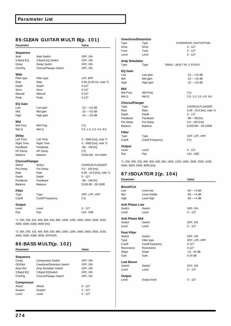
Parameter List
85:CLEAN GUITAR MULTI B(p. 101)Parameter Value
SequenceWah Wah Switch OFF, ON3 Band EQ 3 Band EQ Switch OFF, ONDelay Delay Switch OFF, ONCho/Flg Chorus/Flanger Switch OFF, ON
WahFilter type Filter type LPF, BPFRate Rate 0.05-10.00 Hz, note *2Depth Depth 0-127Sens Sens 0-127Manual Manual 0-127Peak Peak 0-127
EQ GainLow Low gain -15 – +15 dB Mid Mid gain -15 – +15 dB High High gain -15 – +15 dB
MidMid Freq Mid Freq (*1)Mid Q Mid Q 0.5, 1.0, 2.0, 4.0, 8.0
DelayLeft Time Left Time 0 - 3000 [ms], note *2Right Time Right Time 0 - 3000 [ms], note *2Feedback Feedback -98 - +98 [%]HF Damp HF Damp (*2)Balance Balance D100:0W - D0:100W
Chorus/FlangerSelect Select CHORUS,FLANGERPre Delay Pre Delay 0.0 - 100 [ms]Rate Rate 0.05 - 10.0 [Hz], note *2Depth Depth 0 - 127Feedback Feedback -98 - +98 [%]Balance Balance D100:0E - D0:100E
FilterType Type OFF, LPF, HPFCutoff Cutoff Frequency (*1)
OutputLevel Level 0 - 127Pan Pan L64 - 63R
*1: 200, 250, 315, 400, 500, 630, 800, 1000, 1250, 1600, 2000, 2500, 3150, 4000, 5000, 6300, 8000 [Hz]
*2: 200, 250, 315, 400, 500, 630, 800, 1000, 1250, 1600, 2000, 2500, 3150, 4000, 5000, 6300, 8000, BYPASS
86:BASS MULTI(p. 102)Parameter Value
SequenceComp Compressor Switch OFF, ONOD/Dist Overdrive/Distortion Switch OFF, ONAmp Sim Amp Simulator Switch OFF, ON3 Band EQ 3 Band EQSwitch OFF, ONCho/Flg Chorus/Flanger Switch OFF, ON
CompressorAttack Attack 0 - 127Sustain Sustain 0 - 127Level Level 0 - 127
Overdrive/DistortionType Type OVERDRIVE, DISTORTIONDrive Drive 0 - 127Tone Tone 0 - 127Level Level 0 - 127
Amp SimulatorType Type SMALL, BUILT-IN, 2-STACK
EQ GainLow Low gain -15 – +15 dB Mid Mid gain -15 – +15 dB High High gain -15 – +15 dB
MidMid Freq Mid Freq (*1)Mid Q Mid Q 0.5, 1.0, 2.0, 4.0, 8.0
Chorus/FlangerType Type CHORUS,FLANGERRate Rate 0.05 - 10.0 [Hz], note *2Depth Depth 0 - 127Feedback Feedback -98 - +98 [%]Pre Delay Pre Delay 0.0 - 100 [ms]Balance Balance D100:0W - D0:100W
FilterType Type OFF, LPF, HPFCutoff Cutoff Frequency (*1)
OutputLevel Level 0 - 127Pan Pan L64 - 63R
*1: 200, 250, 315, 400, 500, 630, 800, 1000, 1250, 1600, 2000, 2500, 3150, 4000, 5000, 6300, 8000 [Hz]
87:ISOLATOR 2(p. 104)Parameter Value
Boost/CutLow Level low -60 – +4 dBMid Level middle -60 – +4 dB High Level high -60 – +4 dB
Anti Phase LowSwitch Switch OFF, ONLevel Level 0 – 127
Anti Phase MidSwitch Switch OFF, ONLevel Level 0 – 127
Post FilterSwitch Switch OFF, ONType Filter type OFF, LPF, HPFCutoff Cutoff frequency 0-127Resonance Resonance 0-127Slope Slope -12, -24 dBGain Gain 0-24 dB
Low BoostSwitch Switch OFF, ONLevel Level 0 – 127
OutputLevel Output level 0 – 127
274
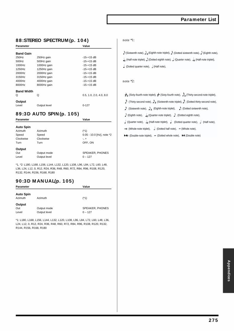
Parameter List
Appen
dices
88:STEREO SPECTRUM(p. 104)Parameter Value
Band Gain250Hz 250Hz gain -15-+15 dB500Hz 500Hz gain -15-+15 dB1000Hz 1000Hz gain -15-+15 dB1250Hz 1250Hz gain -15-+15 dB2000Hz 2000Hz gain -15-+15 dB3150Hz 3150Hz gain -15-+15 dB4000Hz 4000Hz gain -15-+15 dB8000Hz 8000Hz gain -15-+15 dB
Band WidthQ Q 0.5, 1.0, 2.0, 4.0, 8.0
OutputLevel Output level 0-127
89:3D AUTO SPIN(p. 105)Parameter Value
Auto SpinAzimuth Azimuth (*1)Speed Speed 0.05 - 10.0 [Hz], note *2Clockwise Clockwise -, +Turn Turn OFF, ON
OutputOut Output mode SPEAKER, PHONESLevel Output level 0 – 127
*1, *2: L180, L168, L156, L144, L132, L120, L108, L96, L84, L72, L60, L48, L36, L24, L12, 0, R12, R24, R36, R48, R60, R72, R84, R96, R108, R120, R132, R144, R156, R168, R180
90:3D MANUAL(p. 105)Parameter Value
Auto SpinAzimuth Azimuth (*1)
OutputOut Output mode SPEAKER, PHONESLevel Output level 0 – 127
*1: L180, L168, L156, L144, L132, L120, L108, L96, L84, L72, L60, L48, L36, L24, L12, 0, R12, R24, R36, R48, R60, R72, R84, R96, R108, R120, R132, R144, R156, R168, R180
note *1:
note *2:
(Dotted eighth note),(Half-note triplet),
(Eighth note),
(Half-note triplet),(Quarter note),
(Dotted quarter note), (Half note),
(Sixteenth note), (Eighth-note triplet), (Dotted sixteenth note),
(Double note)(Dotted whole note),
(Dotted half note),
(Dotted thirty-second note),
(Whole note),
(Double-note triplet),
(Sixteenth-note triplet),(Thirty-second note),
(Sixty-fourth-note triplet), (Sixty-fourth note), (Thirty-second-note triplet),
(Dotted eighth note),(Quarter-note triplet),(Eighth note),
(Half-note triplet),(Quarter note), (Dotted quarter note),
(Whole-note triplet),
(Half note),
(Sixteenth note), (Eighth-note triplet), (Dotted sixteenth note),
275
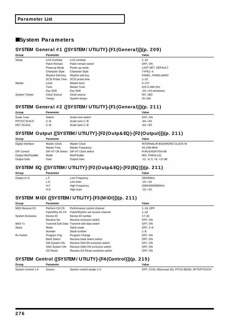
Parameter List
■ System Parameters
SYSTEM General #1 ([SYSTEM/UTILITY]-[F1(General)])(p. 209)Group Parameter Value
Setup LCD Contrast LCD contrast 1–10Patch Remain Patch remain switch OFF, ONPowerup Mode Power up mode LAST-SET, DEFAULTCharacter Style Character Style TYPE1–4Rhythm Edit Key Rhythm edit key PANEL, PANEL&MIDISCSI Probe Time SCSI probe time 1–10
Master Level Master level 0–127Tune Master Tune 415.3–466.2HzKey Shift Key Shift -24–+24 semitones
System Tempo Clock Source Clock source INT, MIDTempo System tempo 20–250
SYSTEM General #2 ([SYSTEM/UTILITY]-[F1(General)])(p. 211)Group Parameter Value
Scale Tune Switch Scale tune switch OFF, ONPATCH SCALE C–B Scale tune C–B -64–+63KEY SCALE C–B Scale tune C–B -64–+63
SYSTEM Output ([SYSTEM/UTILITY]-[F2(Outp&EQ)-[F2(Output)])(p. 211)Group Parameter Value
Digital Interface Master Clock Master Clock INTERNAL/R-BUS/WORD CLOCK INMaster Freq Master Frequency 44.1/48.0kHz
DIF Control DIF-AT Clk Select DIF-AT Clock select R-BUS/ADAT/DA-88Output Mix/Parallel Mode Mix/Parallel MIX, PARALLELOutput Gain Gain Output Gain -12, -6, 0, +6, +12 dB
SYSTEM EQ ([SYSTEM/UTILITY]-[F2(Outp&EQ)-[F2(EQ)])(p. 211)Group Parameter Value
Output-A–D L.F Low Frequency 200/400HzL.G Low Gain -15–+15H.F High Frequency 2000/4000/8000HzH.G High Gain -15–+15
SYSTEM MIDI ([SYSTEM/UTILITY]-[F3(MIDI)])(p. 211)Group Parameter Value
MIDI Receive Ch Perform Ctrl Ch Performance control channel 1–16, OFFPatch/Rhy Rx Ch Patch/Rhythm set receive channel 1–16
System Exclusive Device ID Device ID number 17–32Receive Sw Receive exclusive switch OFF, ON
MIDI Tx Transmit Edit Data Transmit edit data switch OFF, ONStack Mode Stack mode OFF, 2–8
Number Stack number 1–8Rx Switch Program Chg Program Change OFF, ON
Bank Select Receive bank select switch OFF, ONGM System ON Receive GM-ON exclusive switch OFF, ONGM2 System ON Receive GM2-ON exclusive switch OFF, ONGS Reset Receive GS Reset exclusive switch OFF, ON
SYSTEM Control ([SYSTEM/UTILITY]-[F4(Control)])(p. 215)Group Parameter Value
System Control 1-4 Source System control assign 1-4 OFF, CC01–95(except 32), PITCH BEND, AFTERTOUCH
276
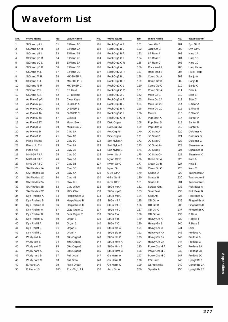
Waveform List
Appen
dices
No. Wave Name
1 StGrand pA L
2 StGrand pA R
3 StGrand pB L
4 StGrand pB R
5 StGrand pC L
6 StGrand pC R
7 StGrand fA L
8 StGrand fA R
9 StGrand fB L
10 StGrand fB R
11 StGrand fC L
12 StGrand fC R
13 Ac Piano2 pA
14 Ac Piano2 pB
15 Ac Piano2 pC
16 Ac Piano2 fA
17 Ac Piano2 fB
18 Ac Piano2 fC
19 Ac Piano1 A
20 Ac Piano1 B
21 Ac Piano1 C
22 Piano Thump
23 Piano Up TH
24 Piano Atk
25 MKS-20 P3 A
26 MKS-20 P3 B
27 MKS-20 P3 C
28 SA Rhodes 1A
29 SA Rhodes 1B
30 SA Rhodes 1C
31 SA Rhodes 2A
32 SA Rhodes 2B
33 SA Rhodes 2C
34 Dyn Rhd mp A
35 Dyn Rhd mp B
36 Dyn Rhd mp C
37 Dyn Rhd mf A
38 Dyn Rhd mf B
39 Dyn Rhd mf C
40 Dyn Rhd ff A
41 Dyn Rhd ff B
42 Dyn Rhd ff C
43 Wurly soft A
44 Wurly soft B
45 Wurly soft C
46 Wurly hard A
47 Wurly hard B
48 Wurly hard C
49 E.Piano 1A
50 E.Piano 1B
No. Wave Name
51 E.Piano 1C
52 E.Piano 2A
53 E.Piano 2B
54 E.Piano 2C
55 E.Piano 3A
56 E.Piano 3B
57 E.Piano 3C
58 MK-80 EP A
59 MK-80 EP B
60 MK-80 EP C
61 EP Hard
62 EP Distone
63 Clear Keys
64 D-50 EP A
65 D-50 EP B
66 D-50 EP C
67 Celesta
68 Music Box
69 Music Box 2
70 Clav 1A
71 Clav 1B
72 Clav 1C
73 Clav 2A
74 Clav 2B
75 Clav 2C
76 Clav 3A
77 Clav 3B
78 Clav 3C
79 Clav 4A
80 Clav 4B
81 Clav 4C
82 Clav Wave
83 MIDI Clav
84 HarpsiWave A
85 HarpsiWave B
86 HarpsiWave C
87 Jazz Organ 1
88 Jazz Organ 2
89 Organ 1
90 Organ 2
91 Organ 3
92 Organ 4
93 60's Organ1
94 60's Organ2
95 60's Organ3
96 60's Organ4
97 Full Organ
98 Full Draw
99 Rock Organ
100 RockOrg1 A L
No. Wave Name
101 RockOrg1 A R
102 RockOrg1 B L
103 RockOrg1 B R
104 RockOrg1 C L
105 RockOrg1 C R
106 RockOrg2 A L
107 RockOrg2 A R
108 RockOrg2 B L
109 RockOrg2 B R
110 RockOrg2 C L
111 RockOrg2 C R
112 RockOrg3 A L
113 RockOrg3 A R
114 RockOrg3 B L
115 RockOrg3 B R
116 RockOrg3 C L
117 RockOrg3 C R
118 Dist. Organ
119 Rot.Org Slw
120 Rot.Org Fst
121 Pipe Organ
122 Soft Nylon A
123 Soft Nylon B
124 Soft Nylon C
125 Nylon Gtr A
126 Nylon Gtr B
127 Nylon Gtr C
128 Nylon Str
129 6-Str Gtr A
130 6-Str Gtr B
131 6-Str Gtr C
132 StlGtr mp A
133 StlGtr mp B
134 StlGtr mp C
135 StlGtr mf A
136 StlGtr mf B
137 StlGtr mf C
138 StlGtr ff A
139 StlGtr ff B
140 StlGtr ff C
141 StlGtr sld A
142 StlGtr sld B
143 StlGtr sld C
144 StlGtr Hrm A
145 StlGtr Hrm B
146 StlGtr Hrm C
147 Gtr Harm A
148 Gtr Harm B
149 Gtr Harm C
150 Jazz Gtr A
No. Wave Name
151 Jazz Gtr B
152 Jazz Gtr C
153 LP Rear A
154 LP Rear B
155 LP Rear C
156 Rock lead 1
157 Rock lead 2
158 Comp Gtr A
159 Comp Gtr B
160 Comp Gtr C
161 Comp Gtr A+
162 Mute Gtr 1
163 Mute Gtr 2A
164 Mute Gtr 2B
165 Mute Gtr 2C
166 Muters
167 Pop Strat A
168 Pop Strat B
169 Pop Strat C
170 JC Strat A
171 JC Strat B
172 JC Strat C
173 JC Strat A+
174 JC Strat B+
175 JC Strat C+
176 Clean Gtr A
177 Clean Gtr B
178 Clean Gtr C
179 Stratus A
180 Stratus B
181 Stratus C
182 Scrape Gut
183 Strat Sust
184 Strat Atk
185 OD Gtr A
186 OD Gtr B
187 OD Gtr C
188 OD Gtr A+
189 Heavy Gtr A
190 Heavy Gtr B
191 Heavy Gtr C
192 Heavy Gtr A+
193 Heavy Gtr B+
194 Heavy Gtr C+
195 PowerChord A
196 PowerChord B
197 PowerChord C
198 EG Harm
199 Gt.FretNoise
200 Syn Gtr A
No. Wave Name
201 Syn Gtr B
202 Syn Gtr C
203 Harp 1A
204 Harp 1B
205 Harp 1C
206 Harp Harm
207 Pluck Harp
208 Banjo A
209 Banjo B
210 Banjo C
211 Sitar A
212 Sitar B
213 Sitar C
214 E.Sitar A
215 E.Sitar B
216 E.Sitar C
217 Santur A
218 Santur B
219 Santur C
220 Dulcimer A
221 Dulcimer B
222 Dulcimer C
223 Shamisen A
224 Shamisen B
225 Shamisen C
226 Koto A
227 Koto B
228 Koto C
229 Taishokoto A
230 Taishokoto B
231 Taishokoto C
232 Pick Bass A
233 Pick Bass B
234 Pick Bass C
235 Fingerd Bs A
236 Fingerd Bs B
237 Fingerd Bs C
238 E.Bass
239 P.Bass 1
240 P.Bass 2
241 Stick
242 Fretless A
243 Fretless B
244 Fretless C
245 Fretless 2A
246 Fretless 2B
247 Fretless 2C
248 UprightBs 1
249 UprightBs 2A
250 UprightBs 2B
277
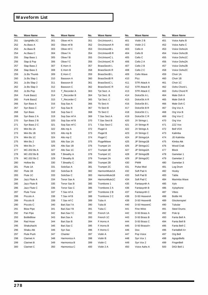
Waveform List
No. Wave Name
251 UprightBs 2C
252 Ac.Bass A
253 Ac.Bass B
254 Ac.Bass C
255 Slap Bass 1
256 Slap & Pop
257 Slap Bass 2
258 Slap Bass 3
259 Jz.Bs Thumb
260 Jz.Bs Slap 1
261 Jz.Bs Slap 2
262 Jz.Bs Slap 3
263 Jz.Bs Pop
264 Funk Bass1
265 Funk Bass2
266 Syn Bass A
267 Syn Bass C
268 Syn Bass
269 Syn Bass 2 A
270 Syn Bass 2 B
271 Syn Bass 2 C
272 Mini Bs 1A
273 Mini Bs 1B
274 Mini Bs 1C
275 Mini Bs 2
276 Mini Bs 2+
277 MC-202 Bs A
278 MC-202 Bs B
279 MC-202 Bs C
280 Hollow Bs
281 Flute 1A
282 Flute 1B
283 Flute 1C
284 Jazz Flute A
285 Jazz Flute B
286 Jazz Flute C
287 Flute Tone
288 Piccolo A
289 Piccolo B
290 Piccolo C
291 Blow Pipe
292 Pan Pipe
293 BottleBlow
294 Rad Hose
295 Shakuhachi
296 Shaku Atk
297 Flute Push
298 Clarinet A
299 Clarinet B
300 Clarinet C
No. Wave Name
301 Oboe mf A
302 Oboe mf B
303 Oboe mf C
304 Oboe f A
305 Oboe f B
306 Oboe f C
307 E.Horn A
308 E.Horn B
309 E.Horn C
310 Bassoon A
311 Bassoon B
312 Bassoon C
313 T_Recorder A
314 T_Recorder B
315 T_Recorder C
316 Sop.Sax A
317 Sop.Sax B
318 Sop.Sax C
319 Sop.Sax mf A
320 Sop.Sax mf B
321 Sop.Sax mf C
322 Alto mp A
323 Alto mp B
324 Alto mp C
325 Alto Sax 1A
326 Alto Sax 1B
327 Alto Sax 1C
328 T.Breathy A
329 T.Breathy B
330 T.Breathy C
331 SoloSax A
332 SoloSax B
333 SoloSax C
334 Tenor Sax A
335 Tenor Sax B
336 Tenor Sax C
337 T.Sax mf A
338 T.Sax mf B
339 T.Sax mf C
340 Bari.Sax f A
341 Bari.Sax f B
342 Bari.Sax f C
343 Bari.Sax A
344 Bari.Sax B
345 Bari.Sax C
346 Syn Sax
347 Chanter
348 Harmonica A
349 Harmonica B
350 Harmonica C
No. Wave Name
351 OrcUnisonA L
352 OrcUnisonA R
353 OrcUnisonB L
354 OrcUnisonB R
355 OrcUnisonC L
356 OrcUnisonC R
357 BrassSectA L
358 BrassSectA R
359 BrassSectB L
360 BrassSectB R
361 BrassSectC L
362 BrassSectC R
363 Tpt Sect. A
364 Tpt Sect. B
365 Tpt Sect. C
366 Tb Sect A
367 Tb Sect B
368 Tb Sect C
369 T.Sax Sect A
370 T.Sax Sect B
371 T.Sax Sect C
372 Flugel A
373 Flugel B
374 Flugel C
375 FlugelWave
376 Trumpet 1A
377 Trumpet 1B
378 Trumpet 1C
379 Trumpet 2A
380 Trumpet 2B
381 Trumpet 2C
382 HarmonMute1A
383 HarmonMute1B
384 HarmonMute1C
385 Trombone 1
386 Trombone 2 A
387 Trombone 2 B
388 Trombone 2 C
389 Tuba A
390 Tuba B
391 Tuba C
392 French 1A
393 French 1C
394 F.Horns A
395 F.Horns B
396 F.Horns C
397 Violin A
398 Violin B
399 Violin C
400 Violin 2 A
No. Wave Name
401 Violin 2 B
402 Violin 2 C
403 Cello A
404 Cello B
405 Cello C
406 Cello 2 A
407 Cello 2 B
408 Cello 2 C
409 Cello Wave
410 Pizz
411 STR Attack A
412 STR Attack B
413 STR Attack C
414 DolceStr.A L
415 DolceStr.A R
416 DolceStr.B L
417 DolceStr.B R
418 DolceStr.C L
419 DolceStr.C R
420 JV Strings L
421 JV Strings R
422 JV Strings A
423 JV Strings C
424 JP Strings1A
425 JP Strings1B
426 JP Strings1C
427 JP Strings2A
428 JP Strings2B
429 JP Strings2C
430 PWM
431 Pulse Mod
432 Soft Pad A
433 Soft Pad B
434 Soft Pad C
435 Fantasynth A
436 Fantasynth B
437 Fantasynth C
438 D-50 HeavenA
439 D-50 HeavenB
440 D-50 HeavenC
441 Fine Wine
442 D-50 Brass A
443 D-50 Brass B
444 D-50 Brass C
445 D-50 BrassA+
446 Doo
447 Pop Voice
448 Syn Vox 1
449 Syn Vox 2
450 Voice Aahs A
No. Wave Name
451 Voice Aahs B
452 Voice Aahs C
453 Voice Oohs1A
454 Voice Oohs1B
455 Voice Oohs1C
456 Voice Oohs2A
457 Voice Oohs2B
458 Voice Oohs2C
459 Choir 1A
460 Choir 1B
461 Choir 1C
462 Oohs Chord L
463 Oohs Chord R
464 Male Ooh A
465 Male Ooh B
466 Male Ooh C
467 Org Vox A
468 Org Vox B
469 Org Vox C
470 Org Vox
471 ZZZ Vox
472 Bell VOX
473 Kalimba
474 JD Kalimba
475 Klmba Atk
476 Wood Crak
477 Block
478 Gamelan 1
479 Gamelan 2
480 Gamelan 3
481 Log Drum
482 Hooky
483 Tabla
484 Marimba Wave
485 Xylo
486 Xylophone
487 Vibes
488 Bottle Hit
489 Glockenspiel
490 Tubular
491 Steel Drums
492 Pole lp
493 Fanta Bell A
494 Fanta Bell B
495 Fanta Bell C
496 FantaBell A+
497 Org Bell
498 AgogoBells
499 FingerBell
500 DIGI Bell 1
278
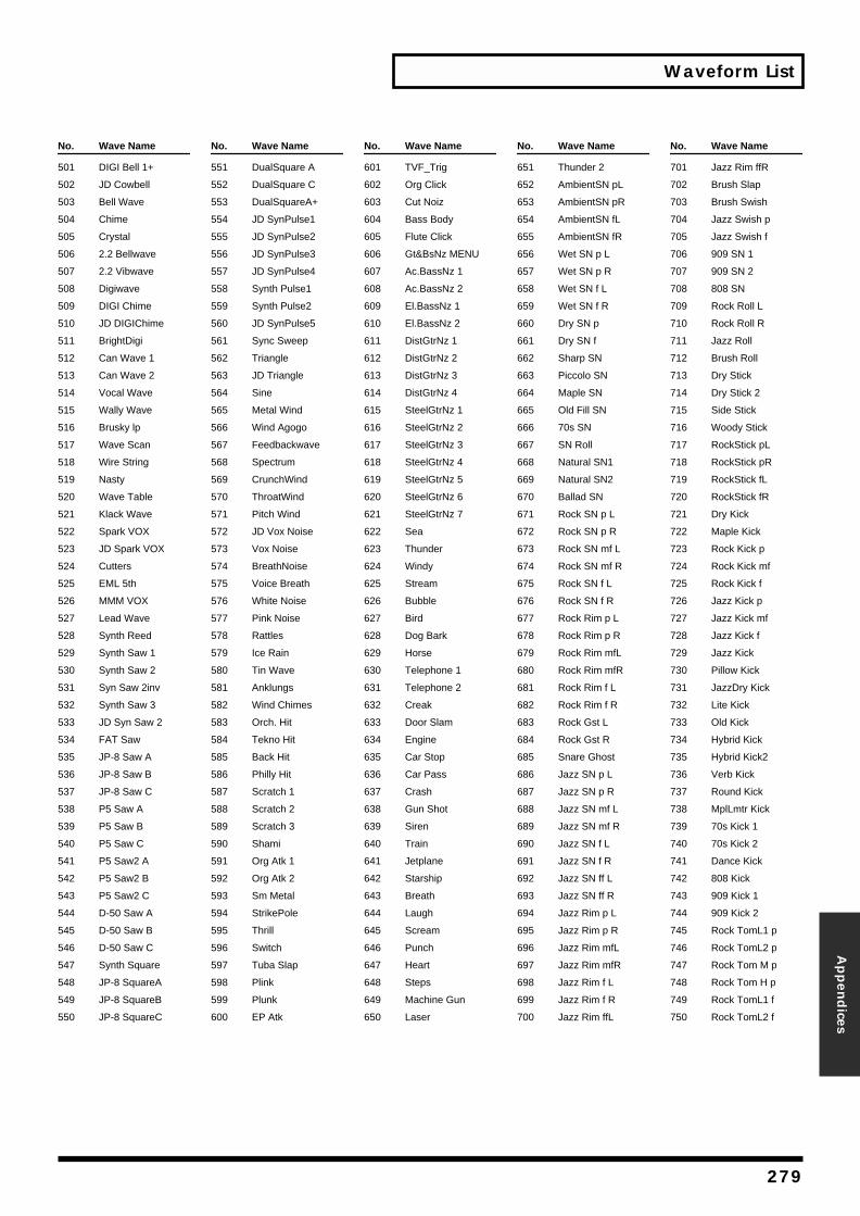
Waveform List
Appen
dices
No. Wave Name
501 DIGI Bell 1+
502 JD Cowbell
503 Bell Wave
504 Chime
505 Crystal
506 2.2 Bellwave
507 2.2 Vibwave
508 Digiwave
509 DIGI Chime
510 JD DIGIChime
511 BrightDigi
512 Can Wave 1
513 Can Wave 2
514 Vocal Wave
515 Wally Wave
516 Brusky lp
517 Wave Scan
518 Wire String
519 Nasty
520 Wave Table
521 Klack Wave
522 Spark VOX
523 JD Spark VOX
524 Cutters
525 EML 5th
526 MMM VOX
527 Lead Wave
528 Synth Reed
529 Synth Saw 1
530 Synth Saw 2
531 Syn Saw 2inv
532 Synth Saw 3
533 JD Syn Saw 2
534 FAT Saw
535 JP-8 Saw A
536 JP-8 Saw B
537 JP-8 Saw C
538 P5 Saw A
539 P5 Saw B
540 P5 Saw C
541 P5 Saw2 A
542 P5 Saw2 B
543 P5 Saw2 C
544 D-50 Saw A
545 D-50 Saw B
546 D-50 Saw C
547 Synth Square
548 JP-8 SquareA
549 JP-8 SquareB
550 JP-8 SquareC
No. Wave Name
551 DualSquare A
552 DualSquare C
553 DualSquareA+
554 JD SynPulse1
555 JD SynPulse2
556 JD SynPulse3
557 JD SynPulse4
558 Synth Pulse1
559 Synth Pulse2
560 JD SynPulse5
561 Sync Sweep
562 Triangle
563 JD Triangle
564 Sine
565 Metal Wind
566 Wind Agogo
567 Feedbackwave
568 Spectrum
569 CrunchWind
570 ThroatWind
571 Pitch Wind
572 JD Vox Noise
573 Vox Noise
574 BreathNoise
575 Voice Breath
576 White Noise
577 Pink Noise
578 Rattles
579 Ice Rain
580 Tin Wave
581 Anklungs
582 Wind Chimes
583 Orch. Hit
584 Tekno Hit
585 Back Hit
586 Philly Hit
587 Scratch 1
588 Scratch 2
589 Scratch 3
590 Shami
591 Org Atk 1
592 Org Atk 2
593 Sm Metal
594 StrikePole
595 Thrill
596 Switch
597 Tuba Slap
598 Plink
599 Plunk
600 EP Atk
No. Wave Name
601 TVF_Trig
602 Org Click
603 Cut Noiz
604 Bass Body
605 Flute Click
606 Gt&BsNz MENU
607 Ac.BassNz 1
608 Ac.BassNz 2
609 El.BassNz 1
610 El.BassNz 2
611 DistGtrNz 1
612 DistGtrNz 2
613 DistGtrNz 3
614 DistGtrNz 4
615 SteelGtrNz 1
616 SteelGtrNz 2
617 SteelGtrNz 3
618 SteelGtrNz 4
619 SteelGtrNz 5
620 SteelGtrNz 6
621 SteelGtrNz 7
622 Sea
623 Thunder
624 Windy
625 Stream
626 Bubble
627 Bird
628 Dog Bark
629 Horse
630 Telephone 1
631 Telephone 2
632 Creak
633 Door Slam
634 Engine
635 Car Stop
636 Car Pass
637 Crash
638 Gun Shot
639 Siren
640 Train
641 Jetplane
642 Starship
643 Breath
644 Laugh
645 Scream
646 Punch
647 Heart
648 Steps
649 Machine Gun
650 Laser
No. Wave Name
651 Thunder 2
652 AmbientSN pL
653 AmbientSN pR
654 AmbientSN fL
655 AmbientSN fR
656 Wet SN p L
657 Wet SN p R
658 Wet SN f L
659 Wet SN f R
660 Dry SN p
661 Dry SN f
662 Sharp SN
663 Piccolo SN
664 Maple SN
665 Old Fill SN
666 70s SN
667 SN Roll
668 Natural SN1
669 Natural SN2
670 Ballad SN
671 Rock SN p L
672 Rock SN p R
673 Rock SN mf L
674 Rock SN mf R
675 Rock SN f L
676 Rock SN f R
677 Rock Rim p L
678 Rock Rim p R
679 Rock Rim mfL
680 Rock Rim mfR
681 Rock Rim f L
682 Rock Rim f R
683 Rock Gst L
684 Rock Gst R
685 Snare Ghost
686 Jazz SN p L
687 Jazz SN p R
688 Jazz SN mf L
689 Jazz SN mf R
690 Jazz SN f L
691 Jazz SN f R
692 Jazz SN ff L
693 Jazz SN ff R
694 Jazz Rim p L
695 Jazz Rim p R
696 Jazz Rim mfL
697 Jazz Rim mfR
698 Jazz Rim f L
699 Jazz Rim f R
700 Jazz Rim ffL
No. Wave Name
701 Jazz Rim ffR
702 Brush Slap
703 Brush Swish
704 Jazz Swish p
705 Jazz Swish f
706 909 SN 1
707 909 SN 2
708 808 SN
709 Rock Roll L
710 Rock Roll R
711 Jazz Roll
712 Brush Roll
713 Dry Stick
714 Dry Stick 2
715 Side Stick
716 Woody Stick
717 RockStick pL
718 RockStick pR
719 RockStick fL
720 RockStick fR
721 Dry Kick
722 Maple Kick
723 Rock Kick p
724 Rock Kick mf
725 Rock Kick f
726 Jazz Kick p
727 Jazz Kick mf
728 Jazz Kick f
729 Jazz Kick
730 Pillow Kick
731 JazzDry Kick
732 Lite Kick
733 Old Kick
734 Hybrid Kick
735 Hybrid Kick2
736 Verb Kick
737 Round Kick
738 MplLmtr Kick
739 70s Kick 1
740 70s Kick 2
741 Dance Kick
742 808 Kick
743 909 Kick 1
744 909 Kick 2
745 Rock TomL1 p
746 Rock TomL2 p
747 Rock Tom M p
748 Rock Tom H p
749 Rock TomL1 f
750 Rock TomL2 f
279
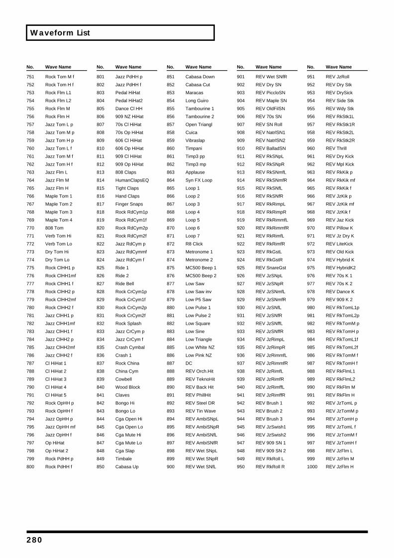
Waveform List
No. Wave Name
751 Rock Tom M f
752 Rock Tom H f
753 Rock Flm L1
754 Rock Flm L2
755 Rock Flm M
756 Rock Flm H
757 Jazz Tom L p
758 Jazz Tom M p
759 Jazz Tom H p
760 Jazz Tom L f
761 Jazz Tom M f
762 Jazz Tom H f
763 Jazz Flm L
764 Jazz Flm M
765 Jazz Flm H
766 Maple Tom 1
767 Maple Tom 2
768 Maple Tom 3
769 Maple Tom 4
770 808 Tom
771 Verb Tom Hi
772 Verb Tom Lo
773 Dry Tom Hi
774 Dry Tom Lo
775 Rock ClHH1 p
776 Rock ClHH1mf
777 Rock ClHH1 f
778 Rock ClHH2 p
779 Rock ClHH2mf
780 Rock ClHH2 f
781 Jazz ClHH1 p
782 Jazz ClHH1mf
783 Jazz ClHH1 f
784 Jazz ClHH2 p
785 Jazz ClHH2mf
786 Jazz ClHH2 f
787 Cl HiHat 1
788 Cl HiHat 2
789 Cl HiHat 3
790 Cl HiHat 4
791 Cl HiHat 5
792 Rock OpHH p
793 Rock OpHH f
794 Jazz OpHH p
795 Jazz OpHH mf
796 Jazz OpHH f
797 Op HiHat
798 Op HiHat 2
799 Rock PdHH p
800 Rock PdHH f
No. Wave Name
801 Jazz PdHH p
802 Jazz PdHH f
803 Pedal HiHat
804 Pedal HiHat2
805 Dance Cl HH
806 909 NZ HiHat
807 70s Cl HiHat
808 70s Op HiHat
809 606 Cl HiHat
810 606 Op HiHat
811 909 Cl HiHat
812 909 Op HiHat
813 808 Claps
814 HumanClapsEQ
815 Tight Claps
816 Hand Claps
817 Finger Snaps
818 Rock RdCym1p
819 Rock RdCym1f
820 Rock RdCym2p
821 Rock RdCym2f
822 Jazz RdCym p
823 Jazz RdCymmf
824 Jazz RdCym f
825 Ride 1
826 Ride 2
827 Ride Bell
828 Rock CrCym1p
829 Rock CrCym1f
830 Rock CrCym2p
831 Rock CrCym2f
832 Rock Splash
833 Jazz CrCym p
834 Jazz CrCym f
835 Crash Cymbal
836 Crash 1
837 Rock China
838 China Cym
839 Cowbell
840 Wood Block
841 Claves
842 Bongo Hi
843 Bongo Lo
844 Cga Open Hi
845 Cga Open Lo
846 Cga Mute Hi
847 Cga Mute Lo
848 Cga Slap
849 Timbale
850 Cabasa Up
No. Wave Name
851 Cabasa Down
852 Cabasa Cut
853 Maracas
854 Long Guiro
855 Tambourine 1
856 Tambourine 2
857 Open Triangl
858 Cuica
859 Vibraslap
860 Timpani
861 Timp3 pp
862 Timp3 mp
863 Applause
864 Syn FX Loop
865 Loop 1
866 Loop 2
867 Loop 3
868 Loop 4
869 Loop 5
870 Loop 6
871 Loop 7
872 R8 Click
873 Metronome 1
874 Metronome 2
875 MC500 Beep 1
876 MC500 Beep 2
877 Low Saw
878 Low Saw inv
879 Low P5 Saw
880 Low Pulse 1
881 Low Pulse 2
882 Low Square
883 Low Sine
884 Low Triangle
885 Low White NZ
886 Low Pink NZ
887 DC
888 REV Orch.Hit
889 REV TeknoHit
890 REV Back Hit
891 REV PhillHit
892 REV Steel DR
893 REV Tin Wave
894 REV AmbiSNpL
895 REV AmbiSNpR
896 REV AmbiSNfL
897 REV AmbiSNfR
898 REV Wet SNpL
899 REV Wet SNpR
900 REV Wet SNfL
No. Wave Name
901 REV Wet SNfR
902 REV Dry SN
903 REV PiccloSN
904 REV Maple SN
905 REV OldFilSN
906 REV 70s SN
907 REV SN Roll
908 REV NatrlSN1
909 REV NatrlSN2
910 REV BalladSN
911 REV RkSNpL
912 REV RkSNpR
913 REV RkSNmfL
914 REV RkSNmfR
915 REV RkSNfL
916 REV RkSNfR
917 REV RkRimpL
918 REV RkRimpR
919 REV RkRimmfL
920 REV RkRimmfR
921 REV RkRimfL
922 REV RkRimfR
923 REV RkGstL
924 REV RkGstR
925 REV SnareGst
926 REV JzSNpL
927 REV JzSNpR
928 REV JzSNmfL
929 REV JzSNmfR
930 REV JzSNfL
931 REV JzSNfR
932 REV JzSNffL
933 REV JzSNffR
934 REV JzRimpL
935 REV JzRimpR
936 REV JzRimmfL
937 REV JzRimmfR
938 REV JzRimfL
939 REV JzRimfR
940 REV JzRimffL
941 REV JzRimffR
942 REV Brush 1
943 REV Brush 2
944 REV Brush 3
945 REV JzSwish1
946 REV JzSwish2
947 REV 909 SN 1
948 REV 909 SN 2
949 REV RkRoll L
950 REV RkRoll R
No. Wave Name
951 REV JzRoll
952 REV Dry Stk
953 REV DrySick
954 REV Side Stk
955 REV Wdy Stk
956 REV RkStk1L
957 REV RkStk1R
958 REV RkStk2L
959 REV RkStk2R
960 REV Thrill
961 REV Dry Kick
962 REV Mpl Kick
963 REV RkKik p
964 REV RkKik mf
965 REV RkKik f
966 REV JzKik p
967 REV JzKik mf
968 REV JzKik f
969 REV Jaz Kick
970 REV Pillow K
971 REV Jz Dry K
972 REV LiteKick
973 REV Old Kick
974 REV Hybrid K
975 REV HybridK2
976 REV 70s K 1
977 REV 70s K 2
978 REV Dance K
979 REV 909 K 2
980 REV RkTomL1p
981 REV RkTomL2p
982 REV RkTomM p
983 REV RkTomH p
984 REV RkTomL1f
985 REV RkTomL2f
986 REV RkTomM f
987 REV RkTomH f
988 REV RkFlmL1
989 REV RkFlmL2
990 REV RkFlm M
991 REV RkFlm H
992 REV JzTomL p
993 REV JzTomM p
994 REV JzTomH p
995 REV JzTomL f
996 REV JzTomM f
997 REV JzTomH f
998 REV JzFlm L
999 REV JzFlm M
1000 REV JzFlm H
280
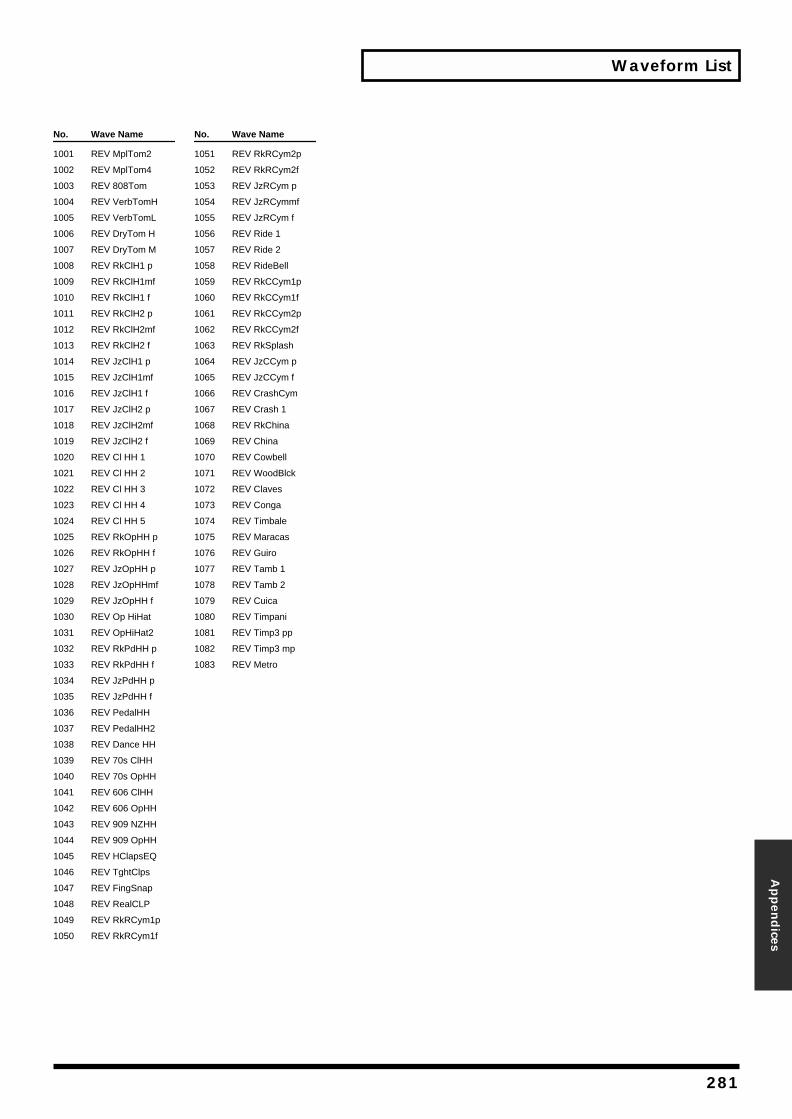
Waveform List
Appen
dices
No. Wave Name
1001 REV MplTom2
1002 REV MplTom4
1003 REV 808Tom
1004 REV VerbTomH
1005 REV VerbTomL
1006 REV DryTom H
1007 REV DryTom M
1008 REV RkClH1 p
1009 REV RkClH1mf
1010 REV RkClH1 f
1011 REV RkClH2 p
1012 REV RkClH2mf
1013 REV RkClH2 f
1014 REV JzClH1 p
1015 REV JzClH1mf
1016 REV JzClH1 f
1017 REV JzClH2 p
1018 REV JzClH2mf
1019 REV JzClH2 f
1020 REV Cl HH 1
1021 REV Cl HH 2
1022 REV Cl HH 3
1023 REV Cl HH 4
1024 REV Cl HH 5
1025 REV RkOpHH p
1026 REV RkOpHH f
1027 REV JzOpHH p
1028 REV JzOpHHmf
1029 REV JzOpHH f
1030 REV Op HiHat
1031 REV OpHiHat2
1032 REV RkPdHH p
1033 REV RkPdHH f
1034 REV JzPdHH p
1035 REV JzPdHH f
1036 REV PedalHH
1037 REV PedalHH2
1038 REV Dance HH
1039 REV 70s ClHH
1040 REV 70s OpHH
1041 REV 606 ClHH
1042 REV 606 OpHH
1043 REV 909 NZHH
1044 REV 909 OpHH
1045 REV HClapsEQ
1046 REV TghtClps
1047 REV FingSnap
1048 REV RealCLP
1049 REV RkRCym1p
1050 REV RkRCym1f
No. Wave Name
1051 REV RkRCym2p
1052 REV RkRCym2f
1053 REV JzRCym p
1054 REV JzRCymmf
1055 REV JzRCym f
1056 REV Ride 1
1057 REV Ride 2
1058 REV RideBell
1059 REV RkCCym1p
1060 REV RkCCym1f
1061 REV RkCCym2p
1062 REV RkCCym2f
1063 REV RkSplash
1064 REV JzCCym p
1065 REV JzCCym f
1066 REV CrashCym
1067 REV Crash 1
1068 REV RkChina
1069 REV China
1070 REV Cowbell
1071 REV WoodBlck
1072 REV Claves
1073 REV Conga
1074 REV Timbale
1075 REV Maracas
1076 REV Guiro
1077 REV Tamb 1
1078 REV Tamb 2
1079 REV Cuica
1080 REV Timpani
1081 REV Timp3 pp
1082 REV Timp3 mp
1083 REV Metro
281
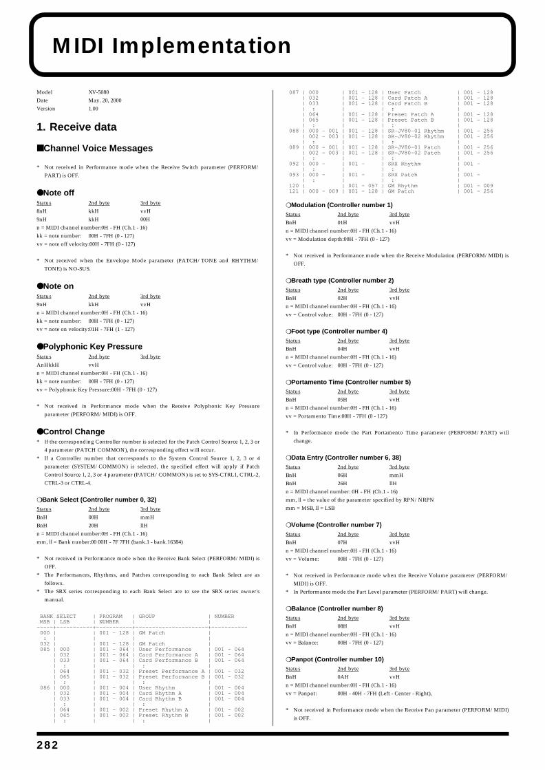
2
MIDI Implementation
Model XV-5080Date May. 20, 2000Version 1.00
1. Receive data
■ Channel Voice Messages
* Not received in Performance mode when the Receive Switch parameter (PERFORM/PART) is OFF.
● Note offStatus 2nd byte 3rd byte8nH kkH vvH9nH kkH 00Hn = MIDI channel number:0H - FH (Ch.1 - 16)kk = note number: 00H - 7FH (0 - 127)vv = note off velocity:00H - 7FH (0 - 127)
* Not received when the Envelope Mode parameter (PATCH/TONE and RHYTHM/TONE) is NO-SUS.
● Note onStatus 2nd byte 3rd byte9nH kkH vvHn = MIDI channel number:0H - FH (Ch.1 - 16)kk = note number: 00H - 7FH (0 - 127)vv = note on velocity:01H - 7FH (1 - 127)
● Polyphonic Key PressureStatus 2nd byte 3rd byteAnHkkH vvHn = MIDI channel number:0H - FH (Ch.1 - 16)kk = note number: 00H - 7FH (0 - 127)vv = Polyphonic Key Pressure:00H - 7FH (0 - 127)
* Not received in Performance mode when the Receive Polyphonic Key Pressureparameter (PERFORM/MIDI) is OFF.
● Control Change* If the corresponding Controller number is selected for the Patch Control Source 1, 2, 3 or
4 parameter (PATCH COMMON), the corresponding effect will occur.* If a Controller number that corresponds to the System Control Source 1, 2, 3 or 4
parameter (SYSTEM/COMMON) is selected, the specified effect will apply if PatchControl Source 1, 2, 3 or 4 parameter (PATCH/COMMON) is set to SYS-CTRL1, CTRL-2,CTRL-3 or CTRL-4.
❍ Bank Select (Controller number 0, 32)Status 2nd byte 3rd byteBnH 00H mmHBnH 20H llHn = MIDI channel number:0H - FH (Ch.1 - 16)mm, ll = Bank nunber:00 00H - 7F 7FH (bank.1 - bank.16384)
* Not received in Performance mode when the Receive Bank Select (PERFORM/MIDI) isOFF.
* The Performances, Rhythms, and Patches corresponding to each Bank Select are asfollows.
* The SRX series corresponding to each Bank Select are to see the SRX series owner'smanual.
BANK SELECT | PROGRAM | GROUP | NUMBER MSB | LSB | NUMBER | | -----+-----------+-----------+----------------------+----------- 000 | | 001 - 128 | GM Patch | : | | | | 032 | | 001 - 128 | GM Patch | 085 | 000 | 001 - 064 | User Performance | 001 - 064 | 032 | 001 - 064 | Card Performance A | 001 - 064 | 033 | 001 - 064 | Card Performance B | 001 - 064 | : | | : | | 064 | 001 - 032 | Preset Performance A | 001 - 032 | 065 | 001 - 032 | Preset Performance B | 001 - 032 | : | | : | 086 | 000 | 001 - 004 | User Rhythm | 001 - 004 | 032 | 001 - 004 | Card Rhythm A | 001 - 004 | 033 | 001 - 004 | Card Rhythm B | 001 - 004 | : | | : | | 064 | 001 - 002 | Preset Rhythm A | 001 - 002 | 065 | 001 - 002 | Preset Rhythm B | 001 - 002 | : | | : |
087 | 000 | 001 - 128 | User Patch | 001 - 128 | 032 | 001 - 128 | Card Patch A | 001 - 128 | 033 | 001 - 128 | Card Patch B | 001 - 128 | : | | : | | 064 | 001 - 128 | Preset Patch A | 001 - 128 | 065 | 001 - 128 | Preset Patch B | 001 - 128 | : | | : | 088 | 000 - 001 | 001 - 128 | SR-JV80-01 Rhythm | 001 - 256 | 002 - 003 | 001 - 128 | SR-JV80-02 Rhythm | 001 - 256 | : | | : | 089 | 000 - 001 | 001 - 128 | SR-JV80-01 Patch | 001 - 256 | 002 - 003 | 001 - 128 | SR-JV80-02 Patch | 001 - 256 | : | | : | 092 | 000 - | 001 - | SRX Rhythm | 001 - | : | | : | 093 | 000 - | 001 - | SRX Patch | 001 - | : | | : | 120 | | 001 - 057 | GM Rhythm | 001 - 009 121 | 000 - 009 | 001 - 128 | GM Patch | 001 - 256
❍ Modulation (Controller number 1)Status 2nd byte 3rd byteBnH 01H vvHn = MIDI channel number:0H - FH (Ch.1 - 16)vv = Modulation depth:00H - 7FH (0 - 127)
* Not received in Performance mode when the Receive Modulation (PERFORM/MIDI) isOFF.
❍ Breath type (Controller number 2)Status 2nd byte 3rd byteBnH 02H vvHn = MIDI channel number:0H - FH (Ch.1 - 16)vv = Control value: 00H - 7FH (0 - 127)
❍ Foot type (Controller number 4)Status 2nd byte 3rd byteBnH 04H vvHn = MIDI channel number:0H - FH (Ch.1 - 16)vv = Control value: 00H - 7FH (0 - 127)
❍ Portamento Time (Controller number 5)Status 2nd byte 3rd byteBnH 05H vvHn = MIDI channel number:0H - FH (Ch.1 - 16)vv = Portamento Time:00H - 7FH (0 - 127)
* In Performance mode the Part Portamento Time parameter (PERFORM/PART) willchange.
❍ Data Entry (Controller number 6, 38)Status 2nd byte 3rd byteBnH 06H mmHBnH 26H llHn = MIDI channel number: 0H - FH (Ch.1 - 16)mm, ll = the value of the parameter specified by RPN/NRPNmm = MSB, ll = LSB
❍ Volume (Controller number 7)Status 2nd byte 3rd byteBnH 07H vvHn = MIDI channel number:0H - FH (Ch.1 - 16)vv = Volume: 00H - 7FH (0 - 127)
* Not received in Performance mode when the Receive Volume parameter (PERFORM/MIDI) is OFF.
* In Performance mode the Part Level parameter (PERFORM/PART) will change.
❍ Balance (Controller number 8)Status 2nd byte 3rd byteBnH 08H vvHn = MIDI channel number:0H - FH (Ch.1 - 16)vv = Balance: 00H - 7FH (0 - 127)
❍ Panpot (Controller number 10)Status 2nd byte 3rd byteBnH 0AH vvHn = MIDI channel number:0H - FH (Ch.1 - 16)vv = Panpot: 00H - 40H - 7FH (Left - Center - Right),
* Not received in Performance mode when the Receive Pan parameter (PERFORM/MIDI)is OFF.
82
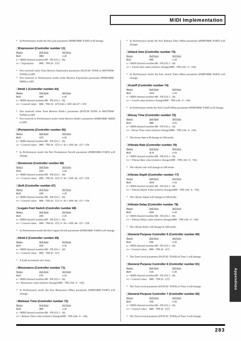
MIDI Implementation
Appen
dices
* In Performance mode the Part pan parameter (PERFORM/PART) will change.
❍ Expression (Controller number 11)Status 2nd byte 3rd byteBnH 0BH vvHn = MIDI channel number:0H - FH (Ch.1 - 16)vv = Expression: 00H - 7FH (0 - 127)
* Not received when Tone Receive Expression parameter (PATCH/TONE or RHYTHM/TONE) is OFF.
* Not received in Performance mode when Receive Expression parameter (PERFORM/MIDI) is OFF.
❍ Hold 1 (Controller number 64)Status 2nd byte 3rd byteBnH 40H vvHn = MIDI channel number:0H - FH (Ch.1 - 16)vv = Control value: 00H - 7FH (0 - 127) 0-63 = OFF, 64-127 = ON
* Not received when Tone Receive Hold-1 parameter (PATCH/TONE or RHYTHM/TONE) is OFF.
* Not received in Performance mode when Receive Hold-1 parameter (PERFORM/MIDI)is OFF.
❍ Portamento (Controller number 65)Status 2nd byte 3rd byteBnH 41H vvHn = MIDI channel number:0H - FH (Ch.1 - 16)vv = Control value: 00H - 7FH (0 - 127) 0 - 63 = OFF, 64 - 127 = ON
* In Performance mode the Part Portamento Switch parameter (PERFORM/PART) willchange.
❍ Sostenuto (Controller number 66)Status 2nd byte 3rd byteBnH 42H vvHn = MIDI channel number:0H - FH (Ch.1 - 16)vv = Control value: 00H - 7FH (0 - 127) 0 - 63 = OFF, 64 - 127 = ON
❍ Soft (Controller number 67)Status 2nd byte 3rd byteBnH 43H vvHn = MIDI channel number:0H - FH (Ch.1 - 16)vv = Control value: 00H - 7FH (0 - 127) 0 - 63 = OFF, 64 - 127 = ON
❍ Legato Foot Switch (Controller number 68)Status 2nd byte 3rd byteBnH 44H vvHn = MIDI channel number:0H - FH (Ch.1 - 16)vv = Control value: 00H - 7FH (0 - 127) 0 - 63 = OFF, 64 - 127 = ON
* In Performance mode the Part Legato Switch parameter (PERFORM/PART) will change.
❍ Hold-2 (Controller number 69)Status 2nd byte 3rd byteBnH 45H vvHn = MIDI channel number:0H - FH (Ch.1 - 16)vv = Control value: 00H - 7FH (0 - 127)
* A hold movement isn't done.
❍ Resonance (Controller number 71)Status 2nd byte 3rd byteBnH 47H vvHn = MIDI channel number:0H - FH (Ch.1 - 16)vv= Resonance value (relative change):00H - 7FH (-64 - 0 - +63),
* In Performance mode the Part Resonance Offset parameter (PERFORM/PART) willchange.
❍ Release Time (Controller number 72)Status 2nd byte 3rd byteBnH 48H vvHn = MIDI channel number:0H - FH (Ch.1 - 16)vv = Release Time value (relative change):00H - 7FH (-64 - 0 - +63),
* In Performance mode the Part Release Time Offset parameter (PERFORM/PART) willchange.
❍ Attack time (Controller number 73)Status 2nd byte 3rd byteBnH 49H vvHn = MIDI channel number:0H - FH (Ch.1 - 16)vv = Attack time value (relative change):00H - 7FH (-64 - 0 - +63),
* In Performance mode the Part Attack Time Offset parameter (PERFORM/PART) willchange.
❍ Cutoff (Controller number 74)Status 2nd byte 3rd byteBnH 4AH vvHn = MIDI channel number:0H - FH (Ch.1 - 16)vv = Cutoff value (relative change):00H - 7FH (-64 - 0 - +63)
* In Performance mode the Part Cutoff Offset parameter (PERFORM/PART) will change.
❍ Decay Time (Controller number 75)Status 2nd byte 3rd byteBnH 4BH vvHn = MIDI channel number:0H - FH (Ch.1 - 16)vv = Decay Time value (relative change):00H - 7FH (-64 - 0 - +63)
* The decay time will change in GM mode.
❍ Vibrato Rate (Controller number 76)Status 2nd byte 3rd byteBnH 4CH vvHn = MIDI channel number:0H - FH (Ch.1 - 16)vv = Vibrato Rate value (relative change):00H - 7FH (-64 - 0 - +63)
* The vibrato rate will change in GM mode.
❍ Vibrato Depth (Controller number 77)Status 2nd byte 3rd byteBnH 4DH vvHn = MIDI channel number:0H - FH (Ch.1 - 16)vv = Vibrato Depth Value (relative change):00H - 7FH (-64 - 0 - +63)
* The vibrato depth will change in GM mode.
❍ Vibrato Delay (Controller number 78)Status 2nd byte 3rd byteBnH 4EH vvHn = MIDI channel number:0H - FH (Ch.1 - 16)vv = Vibrato Delay value (relative change):00H - 7FH (-64 - 0 - +63)
* The vibrato delay will change in GM mode.
❍ General Purpose Controller 5 (Controller number 80)Status 2nd byte 3rd byteBnH 50H vvHn = MIDI channel number:0H - FH (Ch.1 - 16)vv = Control value: 00H - 7FH (0 - 127)
* The Tone Level parameter (PATCH/TONE) of Tone 1 will change.
❍ General Purpose Controller 6 (Controller number 81)Status 2nd byte 3rd byteBnH 51H vvHn = MIDI channel number:0H - FH (Ch.1 - 16)vv = Control value: 00H - 7FH (0 - 127)
* The Tone Level parameter (PATCH/TONE) of Tone 2 will change.
❍ General Purpose Controller 7 (Controller number 82)Status 2nd byte 3rd byteBnH 52H vvHn = MIDI channel number:0H - FH (Ch.1 - 16)vv = Control value: 00H - 7FH (0 - 127)
* The Tone Level parameter (PATCH/TONE) of Tone 3 will change.
283
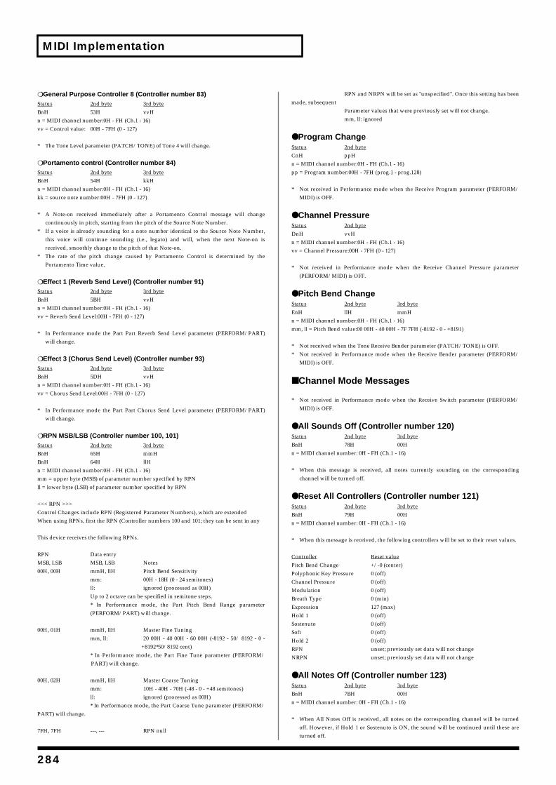
MIDI Implementation
❍ General Purpose Controller 8 (Controller number 83)Status 2nd byte 3rd byteBnH 53H vvHn = MIDI channel number:0H - FH (Ch.1 - 16)vv = Control value: 00H - 7FH (0 - 127)
* The Tone Level parameter (PATCH/TONE) of Tone 4 will change.
❍ Portamento control (Controller number 84)Status 2nd byte 3rd byteBnH 54H kkHn = MIDI channel number:0H - FH (Ch.1 - 16)kk = source note number:00H - 7FH (0 - 127)
* A Note-on received immediately after a Portamento Control message will changecontinuously in pitch, starting from the pitch of the Source Note Number.
* If a voice is already sounding for a note number identical to the Source Note Number,this voice will continue sounding (i.e., legato) and will, when the next Note-on isreceived, smoothly change to the pitch of that Note-on.
* The rate of the pitch change caused by Portamento Control is determined by thePortamento Time value.
❍ Effect 1 (Reverb Send Level) (Controller number 91)Status 2nd byte 3rd byteBnH 5BH vvHn = MIDI channel number:0H - FH (Ch.1 - 16)vv = Reverb Send Level:00H - 7FH (0 - 127)
* In Performance mode the Part Part Reverb Send Level parameter (PERFORM/PART)will change.
❍ Effect 3 (Chorus Send Level) (Controller number 93)Status 2nd byte 3rd byteBnH 5DH vvHn = MIDI channel number:0H - FH (Ch.1 - 16)vv = Chorus Send Level:00H - 7FH (0 - 127)
* In Performance mode the Part Part Chorus Send Level parameter (PERFORM/PART)will change.
❍ RPN MSB/LSB (Controller number 100, 101)Status 2nd byte 3rd byteBnH 65H mmHBnH 64H llHn = MIDI channel number:0H - FH (Ch.1 - 16)mm = upper byte (MSB) of parameter number specified by RPNll = lower byte (LSB) of parameter number specified by RPN
<<< RPN >>>Control Changes include RPN (Registered Parameter Numbers), which are extended When using RPNs, first the RPN (Controller numbers 100 and 101; they can be sent in any
This device receives the following RPNs.
RPN Data entryMSB, LSB MSB, LSB Notes00H, 00H mmH, llH Pitch Bend Sensitivity
mm: 00H - 18H (0 - 24 semitones)ll: ignored (processed as 00H)Up to 2 octave can be specified in semitone steps.* In Performance mode, the Part Pitch Bend Range parameter(PERFORM/PART) will change.
00H, 01H mmH, llH Master Fine Tuningmm, ll: 20 00H - 40 00H - 60 00H (-8192 - 50/ 8192 - 0 -
+8192*50/8192 cent)* In Performance mode, the Part Fine Tune parameter (PERFORM/PART) will change.
00H, 02H mmH, llH Master Coarse Tuningmm: 10H - 40H - 70H (-48 - 0 - +48 semitones)ll: ignored (processed as 00H)* In Performance mode, the Part Coarse Tune parameter (PERFORM/
PART) will change.
7FH, 7FH ---, --- RPN null
RPN and NRPN will be set as "unspecified". Once this setting has beenmade, subsequent
Parameter values that were previously set will not change.mm, ll: ignored
● Program ChangeStatus 2nd byteCnH ppHn = MIDI channel number:0H - FH (Ch.1 - 16)pp = Program number:00H - 7FH (prog.1 - prog.128)
* Not received in Performance mode when the Receive Program parameter (PERFORM/MIDI) is OFF.
● Channel PressureStatus 2nd byteDnH vvHn = MIDI channel number:0H - FH (Ch.1 - 16)vv = Channel Pressure:00H - 7FH (0 - 127)
* Not received in Performance mode when the Receive Channel Pressure parameter(PERFORM/MIDI) is OFF.
● Pitch Bend ChangeStatus 2nd byte 3rd byteEnH llH mmHn = MIDI channel number:0H - FH (Ch.1 - 16)mm, ll = Pitch Bend value:00 00H - 40 00H - 7F 7FH (-8192 - 0 - +8191)
* Not received when the Tone Receive Bender parameter (PATCH/TONE) is OFF.* Not received in Performance mode when the Receive Bender parameter (PERFORM/
MIDI) is OFF.
■ Channel Mode Messages
* Not received in Performance mode when the Receive Switch parameter (PERFORM/MIDI) is OFF.
● All Sounds Off (Controller number 120)Status 2nd byte 3rd byteBnH 78H 00Hn = MIDI channel number: 0H - FH (Ch.1 - 16)
* When this message is received, all notes currently sounding on the correspondingchannel will be turned off.
● Reset All Controllers (Controller number 121)Status 2nd byte 3rd byteBnH 79H 00Hn = MIDI channel number: 0H - FH (Ch.1 - 16)
* When this message is received, the following controllers will be set to their reset values.
Controller Reset valuePitch Bend Change +/-0 (center)Polyphonic Key Pressure 0 (off)Channel Pressure 0 (off)Modulation 0 (off)Breath Type 0 (min)Expression 127 (max)Hold 1 0 (off)Sostenuto 0 (off)Soft 0 (off)Hold 2 0 (off)RPN unset; previously set data will not changeNRPN unset; previously set data will not change
● All Notes Off (Controller number 123)Status 2nd byte 3rd byteBnH 7BH 00Hn = MIDI channel number: 0H - FH (Ch.1 - 16)
* When All Notes Off is received, all notes on the corresponding channel will be turnedoff. However, if Hold 1 or Sostenuto is ON, the sound will be continued until these areturned off.
284
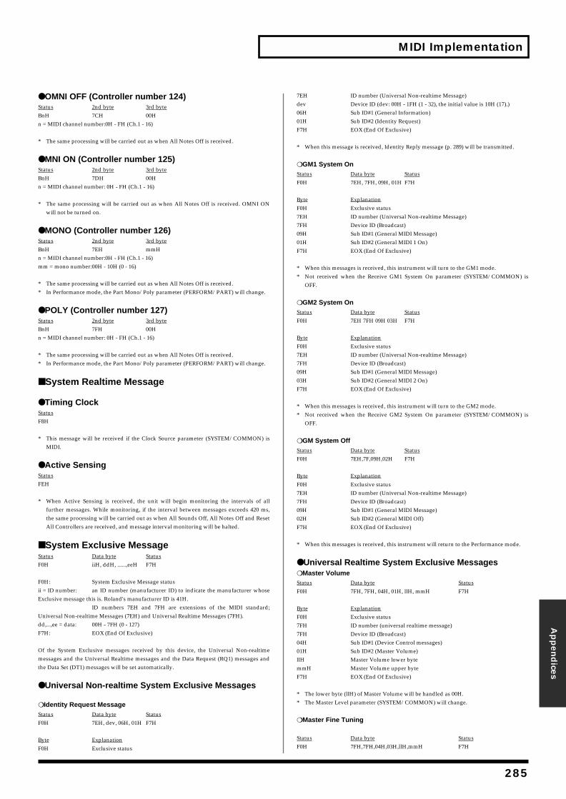
MIDI Implementation
Appen
dices
● OMNI OFF (Controller number 124)Status 2nd byte 3rd byteBnH 7CH 00Hn = MIDI channel number:0H - FH (Ch.1 - 16)
* The same processing will be carried out as when All Notes Off is received.
● MNI ON (Controller number 125)Status 2nd byte 3rd byteBnH 7DH 00Hn = MIDI channel number: 0H - FH (Ch.1 - 16)
* The same processing will be carried out as when All Notes Off is received. OMNI ONwill not be turned on.
● MONO (Controller number 126)Status 2nd byte 3rd byteBnH 7EH mmHn = MIDI channel number:0H - FH (Ch.1 - 16)mm = mono number:00H - 10H (0 - 16)
* The same processing will be carried out as when All Notes Off is received.* In Performance mode, the Part Mono/Poly parameter (PERFORM/PART) will change.
● POLY (Controller number 127)Status 2nd byte 3rd byteBnH 7FH 00Hn = MIDI channel number: 0H - FH (Ch.1 - 16)
* The same processing will be carried out as when All Notes Off is received.* In Performance mode, the Part Mono/Poly parameter (PERFORM/PART) will change.
■ System Realtime Message
● Timing ClockStatusF8H
* This message will be received if the Clock Source parameter (SYSTEM/COMMON) isMIDI.
● Active SensingStatusFEH
* When Active Sensing is received, the unit will begin monitoring the intervals of allfurther messages. While monitoring, if the interval between messages exceeds 420 ms,the same processing will be carried out as when All Sounds Off, All Notes Off and ResetAll Controllers are received, and message interval monitoring will be halted.
■ System Exclusive MessageStatus Data byte StatusF0H iiH, ddH, ......,eeH F7H
F0H: System Exclusive Message statusii = ID number: an ID number (manufacturer ID) to indicate the manufacturer whoseExclusive message this is. Roland's manufacturer ID is 41H.
ID numbers 7EH and 7FH are extensions of the MIDI standard;Universal Non-realtime Messages (7EH) and Universal Realtime Messages (7FH).dd,...,ee = data: 00H - 7FH (0 - 127)F7H: EOX (End Of Exclusive)
Of the System Exclusive messages received by this device, the Universal Non-realtimemessages and the Universal Realtime messages and the Data Request (RQ1) messages andthe Data Set (DT1) messages will be set automatically.
● Universal Non-realtime System Exclusive Messages
❍ Identity Request MessageStatus Data byte StatusF0H 7EH, dev, 06H, 01H F7H
Byte ExplanationF0H Exclusive status
7EH ID number (Universal Non-realtime Message)dev Device ID (dev: 00H - 1FH (1 - 32), the initial value is 10H (17).)06H Sub ID#1 (General Information)01H Sub ID#2 (Identity Request)F7H EOX (End Of Exclusive)
* When this message is received, Identity Reply message (p. 289) will be transmitted.
❍ GM1 System OnStatus Data byte StatusF0H 7EH, 7FH, 09H, 01H F7H
Byte ExplanationF0H Exclusive status7EH ID number (Universal Non-realtime Message)7FH Device ID (Broadcast)09H Sub ID#1 (General MIDI Message)01H Sub ID#2 (General MIDI 1 On)F7H EOX (End Of Exclusive)
* When this messages is received, this instrument will turn to the GM1 mode.* Not received when the Receive GM1 System On parameter (SYSTEM/COMMON) is
OFF.
❍ GM2 System OnStatus Data byte StatusF0H 7EH 7FH 09H 03H F7H
Byte ExplanationF0H Exclusive status7EH ID number (Universal Non-realtime Message)7FH Device ID (Broadcast)09H Sub ID#1 (General MIDI Message)03H Sub ID#2 (General MIDI 2 On)F7H EOX (End Of Exclusive)
* When this messages is received, this instrument will turn to the GM2 mode.* Not received when the Receive GM2 System On parameter (SYSTEM/COMMON) is
OFF.
❍ GM System OffStatus Data byte StatusF0H 7EH,7F,09H,02H F7H
Byte ExplanationF0H Exclusive status7EH ID number (Universal Non-realtime Message)7FH Device ID (Broadcast)09H Sub ID#1 (General MIDI Message)02H Sub ID#2 (General MIDI Off)F7H EOX (End Of Exclusive)
* When this messages is received, this instrument will return to the Performance mode.
● Universal Realtime System Exclusive Messages❍ Master VolumeStatus Data byte StatusF0H 7FH, 7FH, 04H, 01H, llH, mmH F7H
Byte ExplanationF0H Exclusive status7FH ID number (universal realtime message)7FH Device ID (Broadcast)04H Sub ID#1 (Device Control messages)01H Sub ID#2 (Master Volume)llH Master Volume lower bytemmH Master Volume upper byteF7H EOX (End Of Exclusive)
* The lower byte (llH) of Master Volume will be handled as 00H.* The Master Level parameter (SYSTEM/COMMON) will change.
❍ Master Fine Tuning
Status Data byte StatusF0H 7FH,7FH,04H,03H,llH,mmH F7H
285
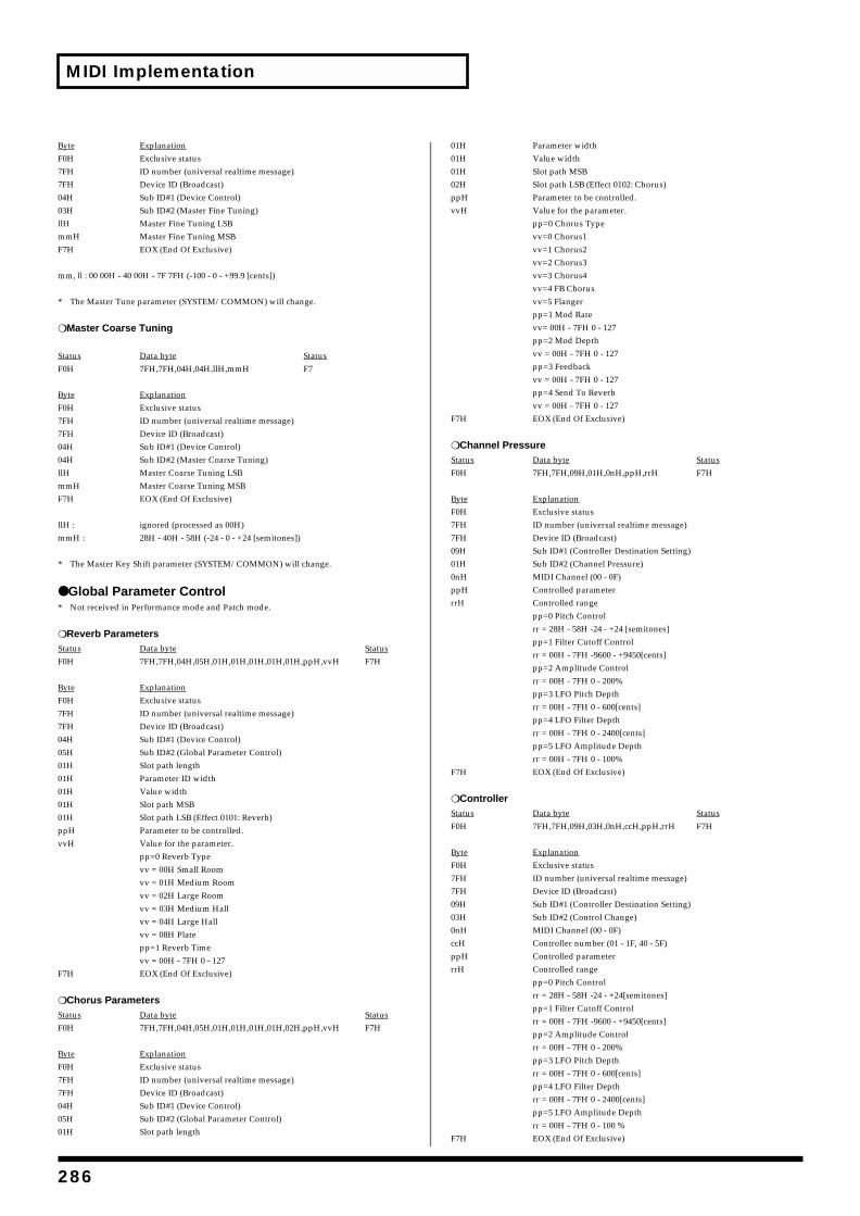
MIDI Implementation
Byte ExplanationF0H Exclusive status7FH ID number (universal realtime message)7FH Device ID (Broadcast)04H Sub ID#1 (Device Control)03H Sub ID#2 (Master Fine Tuning)llH Master Fine Tuning LSBmmH Master Fine Tuning MSBF7H EOX (End Of Exclusive)
mm, ll : 00 00H - 40 00H - 7F 7FH (-100 - 0 - +99.9 [cents])
* The Master Tune parameter (SYSTEM/COMMON) will change.
❍ Master Coarse Tuning
Status Data byte StatusF0H 7FH,7FH,04H,04H,llH,mmH F7
Byte ExplanationF0H Exclusive status7FH ID number (universal realtime message)7FH Device ID (Broadcast)04H Sub ID#1 (Device Control)04H Sub ID#2 (Master Coarse Tuning)llH Master Coarse Tuning LSBmmH Master Coarse Tuning MSBF7H EOX (End Of Exclusive)
llH : ignored (processed as 00H)mmH : 28H - 40H - 58H (-24 - 0 - +24 [semitones])
* The Master Key Shift parameter (SYSTEM/COMMON) will change.
● Global Parameter Control* Not received in Performance mode and Patch mode.
❍ Reverb ParametersStatus Data byte StatusF0H 7FH,7FH,04H,05H,01H,01H,01H,01H,01H,ppH,vvH F7H
Byte ExplanationF0H Exclusive status7FH ID number (universal realtime message)7FH Device ID (Broadcast)04H Sub ID#1 (Device Control)05H Sub ID#2 (Global Parameter Control)01H Slot path length01H Parameter ID width01H Value width01H Slot path MSB01H Slot path LSB (Effect 0101: Reverb)ppH Parameter to be controlled.vvH Value for the parameter.
pp=0 Reverb Typevv = 00H Small Roomvv = 01H Medium Roomvv = 02H Large Roomvv = 03H Medium Hallvv = 04H Large Hallvv = 08H Platepp=1 Reverb Timevv = 00H - 7FH 0 - 127
F7H EOX (End Of Exclusive)
❍ Chorus ParametersStatus Data byte StatusF0H 7FH,7FH,04H,05H,01H,01H,01H,01H,02H,ppH,vvH F7H
Byte ExplanationF0H Exclusive status7FH ID number (universal realtime message)7FH Device ID (Broadcast)04H Sub ID#1 (Device Control)05H Sub ID#2 (Global Parameter Control)01H Slot path length
01H Parameter width01H Value width01H Slot path MSB 02H Slot path LSB (Effect 0102: Chorus) ppH Parameter to be controlled.vvH Value for the parameter.
pp=0 Chorus Typevv=0 Chorus1vv=1 Chorus2vv=2 Chorus3vv=3 Chorus4vv=4 FB Chorusvv=5 Flangerpp=1 Mod Ratevv= 00H - 7FH 0 - 127pp=2 Mod Depthvv = 00H - 7FH 0 - 127pp=3 Feedbackvv = 00H - 7FH 0 - 127pp=4 Send To Reverbvv = 00H - 7FH 0 - 127
F7H EOX (End Of Exclusive)
❍ Channel PressureStatus Data byte StatusF0H 7FH,7FH,09H,01H,0nH,ppH,rrH F7H
Byte ExplanationF0H Exclusive status7FH ID number (universal realtime message)7FH Device ID (Broadcast)09H Sub ID#1 (Controller Destination Setting)01H Sub ID#2 (Channel Pressure)0nH MIDI Channel (00 - 0F)ppH Controlled parameter rrH Controlled range
pp=0 Pitch Controlrr = 28H - 58H -24 - +24 [semitones]pp=1 Filter Cutoff Controlrr = 00H - 7FH -9600 - +9450[cents]pp=2 Amplitude Controlrr = 00H - 7FH 0 - 200%pp=3 LFO Pitch Depthrr = 00H - 7FH 0 - 600[cents]pp=4 LFO Filter Depthrr = 00H - 7FH 0 - 2400[cents]pp=5 LFO Amplitude Depthrr = 00H - 7FH 0 - 100%
F7H EOX (End Of Exclusive)
❍ ControllerStatus Data byte StatusF0H 7FH,7FH,09H,03H,0nH,ccH,ppH,rrH F7H
Byte ExplanationF0H Exclusive status7FH ID number (universal realtime message)7FH Device ID (Broadcast)09H Sub ID#1 (Controller Destination Setting)03H Sub ID#2 (Control Change)0nH MIDI Channel (00 - 0F)ccH Controller number (01 - 1F, 40 - 5F)ppH Controlled parameterrrH Controlled range
pp=0 Pitch Controlrr = 28H - 58H -24 - +24[semitones]pp=1 Filter Cutoff Controlrr = 00H - 7FH -9600 - +9450[cents]pp=2 Amplitude Controlrr = 00H - 7FH 0 - 200%pp=3 LFO Pitch Depthrr = 00H - 7FH 0 - 600[cents]pp=4 LFO Filter Depthrr = 00H - 7FH 0 - 2400[cents]pp=5 LFO Amplitude Depthrr = 00H - 7FH 0 - 100 %
F7H EOX (End Of Exclusive)
286
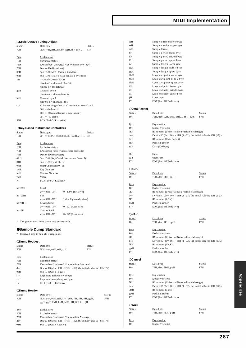
MIDI Implementation
Appen
dices
❍ Scale/Octave Tuning AdjustStatus Data byte StatusF0H 7EH,7FH,08H,08H,ffH,ggH,hhH,ssH... F7H
Byte ExplanationF0H Exclusive status7EH ID number (Universal Non-realtime Message)7FH Device ID (Broadcast)08H Sub ID#1 (MIDI Tuning Standard)08H Sub ID#2 (scale/octave tuning 1-byte form)ffH Channel/Option byte1
bits 0 to 1 = channel 15 to 16bit 2 to 6 = Undefined
ggH Channel byte2 bits 0 to 6 = channel 8 to 14
hhH Channel byte3 bits 0 to 6 = channel 1 to 7
ssH 12 byte tuning offset of 12 semitones from C to B00H = -64 [cents]40H = 0 [cents] (equal temperament)7FH = +63 [cents]
F7H EOX (End Of Exclusive)
❍ Key-Based Instrument ControllersStatus Data byte StatusF0H 7FH,7FH,0AH,01H,0nH,kkH,nnH,vvH... F7H
Byte ExplanationF0H Exclusive status7FH ID number (universal realtime message)7FH Device ID (Broadcast)0AH Sub ID#1 (Key-Based Instrument Control)01H Sub ID#2 (Controller)0nH MIDI Channel (00 - 0F)kkH Key Number nnH Control Number vvH Value F7 EOX (End Of Exclusive)
nn=07H Levelvv = 00H - 7FH 0 - 200% (Relative)
nn=0AH Panvv = 00H - 7FH Left - Right (Absolute)
nn=5BH Reverb Sendvv = 00H - 7FH 0 - 127 (Absolute)
nn=5D Chorus Sendvv = 00H - 7FH 0 - 127 (Absolute)
* This parameter affects drum instruments only.
● Sample Dump Standard* Received only in Sample Dump mode.
❍ Dump RequestStatus Data byte StatusF0H 7EH, dev, 03H, ssH, ssH F7H
Byte ExplanationF0H Exclusive status7EH ID number (Universal Non-realtime Message)dev Device ID (dev: 00H - 1FH (1 - 32), the initial value is 10H (17).)03H Sub ID (Dump Request)ssH Requested sample lower bytessH Requested sample upper byteF7 EOX (End Of Exclusive)
❍ Dump HeaderStatus Data byte StatusF0H 7EH, dev, 01H, ssH, ssH, eeH, ffH, ffH, ffH, ggH, F7H
ggH, ggH, hhH, hhH, hhH, iiH, iiH, iiH, jjH
Byte ExplanationF0H Exclusive status7EH ID number (Universal Non-realtime Message)dev Device ID (dev: 00H - 1FH (1 - 32), the initial value is 10H (17).)01H Sub ID (Dump Header)
ssH Sample number lower bytessH Sample number upper byteeeH Sample formatffH Sample period lower byteffH Sample period middle byteffH Sample period upper byteggH Sample length lower byteggH Sample length middle byteggH Sample length upper bytehhH Loop start point lower bytehhH Loop start point middle bytehhH Loop start point upper byteiiH Loop end point lower byteiiH Loop end point middle byteiiH Loop end point upper bytejjH Loop typeF7 EOX (End Of Exclusive)
❍ Data PacketStatus Data byte StatusF0H 7EH, dev, 02H, kkH, aaH, ... bbH, sum F7H
Byte ExplanationF0H Exclusive status7EH ID number (Universal Non-realtime Message)dev Device ID (dev: 00H - 1FH (1 - 32), the initial value is 10H (17).)02H ID number (Data Packet)kkH Packet numberaaH Data (120 byte) : :bbH Datasum checksumF7H EOX (End Of Exclusive)
❍ ACKStatus Data byte StatusF0H 7EH, dev, 7FH, ppH F7H
Byte ExplanationF0H Exclusive status7EH ID number (Universal Non-realtime Message)dev Device ID (dev: 00H - 1FH (1 - 32), the initial value is 10H (17).)7FH ID number (ACK)ppH Packet numberF7H EOX (End Of Exclusive)
❍ NAKStatus Data byte StatusF0H 7EH, dev, 7EH, ppH F7H
Byte ExplanationF0H Exclusive status7EH ID number (Universal Non-realtime Message)dev Device ID (dev: 00H - 1FH (1 - 32), the initial value is 10H (17).)7EH ID number (NAK)ppH Packet numberF7H EOX (End Of Exclusive)
❍ CancelStatus Data byte StatusF0H 7EH, dev, 7DH, ppH F7H
Byte ExplanationF0H Exclusive status7EH ID number (Universal Non-realtime Message)dev Device ID (dev: 00H - 1FH (1 - 32), the initial value is 10H (17).)7DH ID number (Cancel)ppH Packet numberF7H EOX (End Of Exclusive)
❍ WaitStatus Data byte StatusF0H 7EH, dev, 7CH, ppH F7H
Byte ExplanationF0H Exclusive status
287
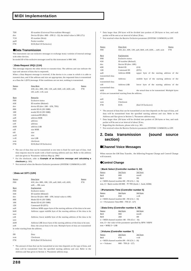
MIDI Implementation
7EH ID number (Universal Non-realtime Message)dev Device ID (dev: 00H - 1FH (1 - 32), the initial value is 10H (17).)7CH ID number (Wait)ppH Packet numberF7H EOX (End Of Exclusive)
● Data TransmissionThis instrument can use exclusive messages to exchange many varieties of internal settingswith other devices.he model ID of the exclusive messages used by this instrument is 00H 10H.
❍ Data Request 1RQ1 (11H)This message requests the other device to transmit data. The address and size indicate thetype and amount of data that is requested.When a Data Request message is received, if the device is in a state in which it is able totransmit data, and if the address and size are appropriate, the requested data is transmittedas a Data Set 1 (DT1) message. If the conditions are not met, nothing is transmitted.
Status Data Byte StatusF0H 41H, dev, 00H, 10H, 11H, aaH, bbH, ccH, ddH, ssH, F7H
ttH, uuH, vvH, sum
Byte RemarksF0H Exclusive status41H ID number (Roland)dev device ID (dev: 10H - 1FH, 7FH)00H model ID #1 (XV-5080)10H model ID #2 (XV-5080)11H commandID (RQ1)aaH address MSBbbH addressccH addressddH address LSBssH size MSBttH sizeuuH sizevvH size LSBsum checksumF7H EOX (End Of Exclusive)
* The size of data that can be transmitted at one time is fixed for each type of data. Anddata requests must be made with a fixed starting address and size. Refer to the addressand size given in "Parameter Address Map (p. 290)".
* For the checksum, refer to Example of an Exclusive message and calculating a
checksum (p. 303).* Not received when the Receive Exclusive parameter (SYSTEM/COMMON) is OFF.
❍ Data set 1DT1 (12H)
Status Data byte StatusF0H 41H, dev, 00H, 10H, 12H, aaH, bbH, ccH, ddH, F7H
eeH, ... ffH, sum Byte ExplanationF0H Exclusive status41H ID number (Roland)dev Device ID (dev: 00H - 1FH, Initial value is 10H)00H Model ID #1 (XV-5080)10H Model ID #2 (XV-5080)12H Command ID (DT1)aaH Address MSB: upper byte of the starting address of the data to be sentbbH Address: upper middle byte of the starting address of the data to besentccH Address: lower middle byte of the starting address of the data to besentddH Address LSB: lower byte of the starting address of the data to be sent.eeH Data: the actual data to be sent. Multiple bytes of data are transmittedin order starting from the address. : :ffH Datasum ChecksumF7H EOX (End Of Exclusive)
* The amount of data that can be transmitted at one time depends on the type of data, anddata will be transmitted from the specified starting address and size. Refer to theAddress and Size given in Section 3, "Parameter address map.
* Data larger than 256 bytes will be divided into packets of 256 bytes or less, and eachpacket will be sent at an interval of about 20 ms.
* Not received when the Receive Exclusive parameter (SYSTEM/COMMON) is OFF.
Status Data byte StatusF0H 41H, dev, 42H, 12H, aaH, bbH, ccH, ddH, ... eeH, sum F7H
Byte ExplanationF0H Exclusive status41H ID number (Roland)dev Device ID (dev: 10H)42H Model ID (GS)12H Command ID (DT1)aaH Address MSB: upper byte of the starting address of thetransmitted databbH Address: middle byte of the starting address of thetransmitted dataccH Address LSB: lower byte of the starting address of thetransmitted dataddH Data: the actual data to be transmitted. Multiple bytesof data are transmitted starting from the address. : :eeH Datasum ChecksumF7H EOX (End Of Exclusive)
* The amount of data that can be transmitted at one time depends on the type of data, anddata will be transmitted from the specified starting address and size. Refer to theAddress and Size given in Section 3, "Parameter address map.
* Data larger than 256 bytes will be divided into packets of 256 bytes or less, and eachpacket will be sent at an interval of about 20 ms.
* Regarding the checksum, please refer to p. 303 .* Not received when the Receive Exclusive parameter (SYSTEM/COMMON) is OFF.
2. Data transmission (sound sourcesection)
■ Channel Voice Messages
When execute the GM Data Transfer, the following Program Change and Control Changewill transmit.
● Control Change
❍ Bank Select (Controller number 0, 32)Status 2nd byte 3rd byteBnH 00H mmHBnH 20H llHn = MIDI channel number:0H - FH (Ch.1 - 16)mm, ll = Bank nunber:00 00H - 7F 7FH (bank.1 - bank.16384)
❍ Portamento Time (Controller number 5)Status 2nd byte 3rd byteBnH 05H vvHn = MIDI channel number:0H - FH (Ch.1 - 16)vv = Portamento Time:00H - 7FH (0 - 127)
❍ Data Entry (Controller number 6, 38)Status 2nd byte 3rd byteBnH 06H mmHBnH 26H llHn = MIDI channel number: 0H - FH (Ch.1 - 16)mm, ll = the value of the parameter specified by RPN/NRPNmm = MSB, ll = LSB
❍ Volume (Controller number 7)Status 2nd byte 3rd byteBnH 07H vvHn = MIDI channel number:0H - FH (Ch.1 - 16)vv = Volume: 00H - 7FH (0 - 127)
288
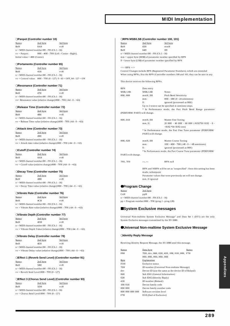
MIDI Implementation
Appen
dices
❍ Panpot (Controller number 10)Status 2nd byte 3rd byteBnH 0AH vvHn = MIDI channel number:0H - FH (Ch.1 - 16)vv = Panpot: 00H - 40H - 7FH (Left - Center - Right), Initial value = 40H (Center)
❍ Portamento (Controller number 65)Status 2nd byte 3rd byteBnH 41H vvHn = MIDI channel number:0H - FH (Ch.1 - 16)vv = Control value: 00H - 7FH (0 - 127) 0 - 63 = OFF, 64 - 127 = ON
❍ Resonance (Controller number 71)Status 2nd byte 3rd byteBnH 47H vvHn = MIDI channel number:0H - FH (Ch.1 - 16)vv= Resonance value (relative change):00H - 7FH (-64 - 0 - +63)
❍ Release Time (Controller number 72)Status 2nd byte 3rd byteBnH 48H vvHn = MIDI channel number:0H - FH (Ch.1 - 16)vv = Release Time value (relative change):00H - 7FH (-64 - 0 - +63)
❍ Attack time (Controller number 73)Status 2nd byte 3rd byteBnH 49H vvHn = MIDI channel number:0H - FH (Ch.1 - 16)vv = Attack time value (relative change):00H - 7FH (-64 - 0 - +63)
❍ Cutoff (Controller number 74)Status 2nd byte 3rd byteBnH 4AH vvHn = MIDI channel number:0H - FH (Ch.1 - 16)vv = Cutoff value (relative change):00H - 7FH (-64 - 0 - +63)
❍ Decay Time (Controller number 75)Status 2nd byte 3rd byteBnH 4BH vvHn = MIDI channel number:0H - FH (Ch.1 - 16)vv = Decay Time value (relative change):00H - 7FH (-64 - 0 - +63)
❍ Vibrato Rate (Controller number 76)Status 2nd byte 3rd byteBnH 4CH vvHn = MIDI channel number:0H - FH (Ch.1 - 16)vv = Vibrato Rate value (relative change):00H - 7FH (-64 - 0 - +63)
❍ Vibrato Depth (Controller number 77)Status 2nd byte 3rd byteBnH 4DH vvHn = MIDI channel number:0H - FH (Ch.1 - 16)vv = Vibrato Depth Value (relative change):00H - 7FH (-64 - 0 - +63)
❍ Vibrato Delay (Controller number 78)Status 2nd byte 3rd byteBnH 4EH vvHn = MIDI channel number:0H - FH (Ch.1 - 16)vv = Vibrato Delay value (relative change):00H - 7FH (-64 - 0 - +63)
❍ Effect 1 (Reverb Send Level) (Controller number 91)Status 2nd byte 3rd byteBnH 5BH vvHn = MIDI channel number:0H - FH (Ch.1 - 16)vv = Reverb Send Level:00H - 7FH (0 - 127)
❍ Effect 3 (Chorus Send Level) (Controller number 93)Status 2nd byte 3rd byteBnH 5DH vvHn = MIDI channel number:0H - FH (Ch.1 - 16)vv = Chorus Send Level:00H - 7FH (0 - 127)
❍ RPN MSB/LSB (Controller number 100, 101)Status 2nd byte 3rd byteBnH 65H mmHBnH 64H llHn = MIDI channel number:0H - FH (Ch.1 - 16)mm = upper byte (MSB) of parameter number specified by RPNll = lower byte (LSB) of parameter number specified by RPN
<<< RPN >>>Control Changes include RPN (Registered Parameter Numbers), which are extended When using RPNs, first the RPN (Controller numbers 100 and 101; they can be sent in any
This device receives the following RPNs.
RPN Data entryMSB, LSB MSB, LSB Notes00H, 00H mmH, llH Pitch Bend Sensitivity
mm: 00H - 18H (0 - 24 semitones)ll: ignored (processed as 00H)Up to 2 octave can be specified in semitone steps.* In Performance mode, the Part Pitch Bend Range parameter
(PERFORM/PART) will change.
00H, 01H mmH, llH Master Fine Tuningmm, ll: 20 00H - 40 00H - 60 00H (-8192*50/8192 - 0 -
+8192 *50/8192 cent)* In Performance mode, the Part Fine Tune parameter (PERFORM/PART) will change.
00H, 02H mmH, llH Master Coarse Tuningmm: 10H - 40H - 70H (-48 - 0 - +48 semitones)ll: ignored (processed as 00H)* In Performance mode, the Part Coarse Tune parameter (PERFORM/
PART) will change.
7FH, 7FH ---, --- RPN null
RPN and NRPN will be set as "unspecified". Once this setting has beenmade, subsequent Parameter values that were previously set will not change.mm, ll: ignored
● Program ChangeStatus 2nd byteCnH ppHn = MIDI channel number:0H - FH (Ch.1 - 16)pp = Program number:00H - 7FH (prog.1 - prog.128)
■ System Exclusive messages
Universal Non-realtime System Exclusive Message" and Data Set 1 (DT1) are the onlySystem Exclusive messages transmitted by the XV-5080.
● Universal Non-realtime System Exclusive Message
❍ Identity Reply Message
Receiving Identity Request Message, the XV-5080 send this message.
Status Data byte StatusF0H 7EH, dev, 06H, 02H, 41H, 10H, 01H, 00H, F7H
00H, 00H, 00H, 00H, 00H Byte ExplanationFOH Exclusive status7EH ID number (Universal Non-realtime Message)dev Device ID (use the same as the device ID of Roland)06H Sub ID#1 (General Information)02H Sub ID#2 (Identity Reply)41H ID number (Roland)10H 01H Device family code00H 00H Device family number code00H 00H 00H 00H Software revision levelF7H EOX (End of Exclusive)
289
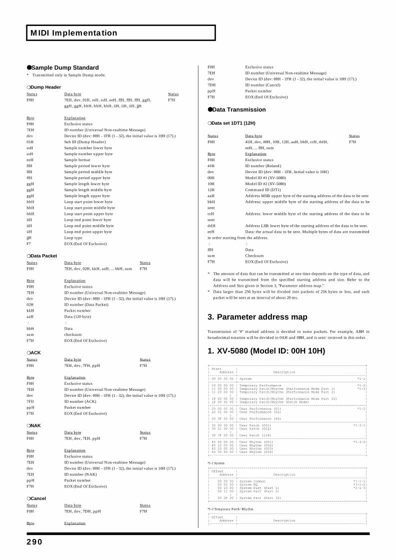
MIDI Implementation
● Sample Dump Standard* Transmitted only in Sample Dump mode.
❍ Dump HeaderStatus Data byte StatusF0H 7EH, dev, 01H, ssH, ssH, eeH, ffH, ffH, ffH, ggH, F7H
ggH, ggH, hhH, hhH, hhH, iiH, iiH, iiH, jjH
Byte ExplanationF0H Exclusive status7EH ID number (Universal Non-realtime Message)dev Device ID (dev: 00H - 1FH (1 - 32), the initial value is 10H (17).)01H Sub ID (Dump Header)ssH Sample number lower bytessH Sample number upper byteeeH Sample formatffH Sample period lower byteffH Sample period middle byteffH Sample period upper byteggH Sample length lower byteggH Sample length middle byteggH Sample length upper bytehhH Loop start point lower bytehhH Loop start point middle bytehhH Loop start point upper byteiiH Loop end point lower byteiiH Loop end point middle byteiiH Loop end point upper bytejjH Loop typeF7 EOX (End Of Exclusive)
❍ Data PacketStatus Data byte StatusF0H 7EH, dev, 02H, kkH, aaH, ... bbH, sum F7H
Byte ExplanationF0H Exclusive status7EH ID number (Universal Non-realtime Message)dev Device ID (dev: 00H - 1FH (1 - 32), the initial value is 10H (17).)02H ID number (Data Packet)kkH Packet numberaaH Data (120 byte) : :bbH Datasum checksumF7H EOX (End Of Exclusive)
❍ ACKStatus Data byte StatusF0H 7EH, dev, 7FH, ppH F7H
Byte ExplanationF0H Exclusive status7EH ID number (Universal Non-realtime Message)dev Device ID (dev: 00H - 1FH (1 - 32), the initial value is 10H (17).)7FH ID number (ACK)ppH Packet numberF7H EOX (End Of Exclusive)
❍ NAKStatus Data byte StatusF0H 7EH, dev, 7EH, ppH F7H
Byte ExplanationF0H Exclusive status7EH ID number (Universal Non-realtime Message)dev Device ID (dev: 00H - 1FH (1 - 32), the initial value is 10H (17).)7EH ID number (NAK)ppH Packet numberF7H EOX (End Of Exclusive)
❍ CancelStatus Data byte StatusF0H 7EH, dev, 7DH, ppH F7H
Byte Explanation
F0H Exclusive status7EH ID number (Universal Non-realtime Message)dev Device ID (dev: 00H - 1FH (1 - 32), the initial value is 10H (17).)7DH ID number (Cancel)ppH Packet numberF7H EOX (End Of Exclusive)
● Data Transmission
❍ Data set 1DT1 (12H)
Status Data byte StatusF0H 41H, dev, 00H, 10H, 12H, aaH, bbH, ccH, ddH, F7H
eeH, ... ffH, sum Byte ExplanationF0H Exclusive status41H ID number (Roland)dev Device ID (dev: 00H - 1FH, Initial value is 10H)00H Model ID #1 (XV-5080)10H Model ID #2 (XV-5080)12H Command ID (DT1)aaH Address MSB: upper byte of the starting address of the data to be sentbbH Address: upper middle byte of the starting address of the data to besentccH Address: lower middle byte of the starting address of the data to besentddH Address LSB: lower byte of the starting address of the data to be sent.eeH Data: the actual data to be sent. Multiple bytes of data are transmittedin order starting from the address. : :ffH Datasum ChecksumF7H EOX (End Of Exclusive)
* The amount of data that can be transmitted at one time depends on the type of data, anddata will be transmitted from the specified starting address and size. Refer to theAddress and Size given in Section 3, "Parameter address map."
* Data larger than 256 bytes will be divided into packets of 256 bytes or less, and eachpacket will be sent at an interval of about 20 ms.
3. Parameter address map
Transmission of "#" marked address is devided to some packets. For example, ABH inhexadecimal notation will be devided to 0AH and 0BH, and is sent/recieved in this order.
1. XV-5080 (Model ID: 00H 10H)
+——————————————————————————————————————————————————————————————————————————————+| Start | || Address | Description ||—————————————+————————————————————————————————————————————————————————————————|| 00 00 00 00 | System *1-1||—————————————+————————————————————————————————————————————————————————————————|| 10 00 00 00 | Temporary Performance *1-2|| 11 00 00 00 | Temporary Patch/Rhythm (Performance Mode Part 1) *1-3|| 11 20 00 00 | Temporary Patch/Rhythm (Performance Mode Part 2) || : | || 18 60 00 00 | Temporary Patch/Rhythm (Performance Mode Part 32) || 1F 00 00 00 | Temporary Patch/Rhythm (Patch Mode) ||—————————————+————————————————————————————————————————————————————————————————|| 20 00 00 00 | User Performance (01) *1-2|| 20 01 00 00 | User Performance (02) || : | || 20 3F 00 00 | User Performance (64) ||—————————————+————————————————————————————————————————————————————————————————|| 30 00 00 00 | User Patch (001) *1-3-1|| 30 01 00 00 | User Patch (002) || : | || 30 7F 00 00 | User Patch (128) ||—————————————+————————————————————————————————————————————————————————————————|| 40 00 00 00 | User Rhythm (001) *1-3-2|| 40 10 00 00 | User Rhythm (002) || 40 20 00 00 | User Rhythm (003) || 40 30 00 00 | User Rhythm (004) |+——————————————————————————————————————————————————————————————————————————————+
*1-1 System+——————————————————————————————————————————————————————————————————————————————+| Offset | || Address | Description ||—————————————+————————————————————————————————————————————————————————————————|| 00 00 00 | System Common *1-1-1|| 00 02 00 | System EQ *1-1-2|| 00 10 00 | System Part (Part 1) *1-1-3|| 00 11 00 | System Part (Part 2) || : | || 00 2F 00 | System Part (Part 32) |+——————————————————————————————————————————————————————————————————————————————+
*1-3 Temporary Patch/Rhythm+——————————————————————————————————————————————————————————————————————————————+| Offset | || Address | Description ||—————————————+————————————————————————————————————————————————————————————————|
290

MIDI Implementation
Appen
dices
| 00 00 00 | Temporary Patch *1-3-1|| 10 00 00 | Temporary Rhythm *1-3-2|+——————————————————————————————————————————————————————————————————————————————+
*1-2 Performance+——————————————————————————————————————————————————————————————————————————————+| Offset | || Address | Description ||—————————————+————————————————————————————————————————————————————————————————|| 00 00 00 | Performance Common *1-2-1|| 00 02 00 | Performance Common MFX *1-2-2|| 00 04 00 | Performance Common Chorus *1-2-3|| 00 06 00 | Performance Common Reverb *1-2-4|| 00 10 00 | Performance MIDI (Channel 1) *1-2-5|| 00 11 00 | Performance MIDI (Channel 2) || : | || 00 1F 00 | Performance MIDI (Channel 16) *1-2-6|| 00 20 00 | Performance Part (Part 1) || 00 21 00 | Performance Part (Part 2) || : | || 00 3F 00 | Performance Part (Part 32) |+——————————————————————————————————————————————————————————————————————————————+
*1-3-1 Patch+——————————————————————————————————————————————————————————————————————————————+| Offset | || Address | Description ||—————————————+————————————————————————————————————————————————————————————————|| 00 00 00 | Patch Common *1-3-1-1|| 00 02 00 | Patch Common MFX *1-3-1-2|| 00 04 00 | Patch Common Chorus *1-3-1-3|| 00 06 00 | Patch Common Reverb *1-3-1-4|| 00 10 00 | Patch TMT (Tone Mix Table) *1-3-1-5|| 00 20 00 | Patch Tone (Tone 1) *1-3-1-6|| 00 22 00 | Patch Tone (Tone 2) || 00 24 00 | Patch Tone (Tone 3) || 00 26 00 | Patch Tone (Tone 4) || 00 30 00 | Patch Split Key (Key # 21) *1-3-1-7|| 00 30 20 | Patch Split Key (Key # 22) || : | || 00 45 60 | Patch Split Key (Key # 108) |+——————————————————————————————————————————————————————————————————————————————+
*1-3-2 Rhythm+——————————————————————————————————————————————————————————————————————————————+| Offset | || Address | Description ||—————————————+————————————————————————————————————————————————————————————————|| 00 00 00 | Rhythm Common *1-3-2-1|| 00 02 00 | Rhythm Common MFX *1-3-2-2|| 00 04 00 | Rhythm Common Chorus *1-3-2-3|| 00 06 00 | Rhythm Common Reverb *1-3-2-4|| 00 10 00 | Rhythm Tone (Key # 21) *1-3-2-5|| 00 12 00 | Rhythm Tone (Key # 22) || : | || 01 3E 00 | Rhythm Tone (Key # 108) |+——————————————————————————————————————————————————————————————————————————————+
*1-1-1 System Common+——————————————————————————————————————————————————————————————————————————————+| Offset | || Address | Description ||—————————————+————————————————————————————————————————————————————————————————|| 00 00 | 0000 0aaa | Sound Mode (0 - 4) || | | PERFORM, PATCH, GM1, GM2, GS ||# 00 01 | 0000 aaaa | || | 0000 bbbb | || | 0000 cccc | || | 0000 dddd | Master Tune (24 - 2024) || | | -100.0 - 100.0 [cent] || 00 05 | 00aa aaaa | Master Key Shift (40 - 88) || | | -24 - +24 || 00 06 | 0aaa aaaa | Master Level (0 - 127) || 00 07 | 0000 000a | Scale Tune Switch (0 - 1) || | | OFF, ON || 00 08 | 0000 000a | Patch Remain (0 - 1) || | | OFF, ON || 00 09 | 0000 000a | Mix/Parallel (0 - 1) || | | MIX, PARALLEL ||—————————————+———————————+————————————————————————————————————————————————————|| 00 0A | 0000 000a | MFX Switch (0 - 1) || | | BYPASS, ON || 00 0B | 0000 000a | Chorus Switch (0 - 1) || | | OFF, ON || 00 0C | 0000 000a | Reverb Switch (0 - 1) || | | OFF, ON ||—————————————+———————————+————————————————————————————————————————————————————|| 00 0D | 000a aaaa | Performance Control Channel (0 - 16) || | | 1 - 16, OFF || 00 0E | 0aaa aaaa | Performance Bank Select MSB (CC# 0) (0 - 127) || 00 0F | 0aaa aaaa | Performance Bank Select LSB (CC# 32) (0 - 127) || 00 10 | 0aaa aaaa | Performance Program Number (PC) (0 - 127) ||—————————————+———————————+————————————————————————————————————————————————————|| 00 11 | 0000 aaaa | Patch Receive Channel (0 - 15) || | | 1 - 16 || 00 12 | 0aaa aaaa | Patch Bank Select MSB (CC# 0) (0 - 127) || 00 13 | 0aaa aaaa | Patch Bank Select LSB (CC# 32) (0 - 127) || 00 14 | 0aaa aaaa | Patch Program Number (PC) (0 - 127) ||—————————————+———————————+————————————————————————————————————————————————————|| 00 15 | 0000 000a | System Clock Source (0 - 1) || | | INT, MIDI ||# 00 16 | 0000 aaaa | || | 0000 bbbb | System Tempo (20 - 250) ||—————————————+———————————+————————————————————————————————————————————————————|| 00 18 | 0aaa aaaa | System Control 1 Source (0 - 97) || | | OFF, CC01 - CC31, CC33 - CC95, || | | BEND, AFT || 00 19 | 0aaa aaaa | System Control 2 Source (0 - 97) || | | OFF, CC01 - CC31, CC33 - CC95, || | | BEND, AFT || 00 1A | 0aaa aaaa | System Control 3 Source (0 - 97) || | | OFF, CC01 - CC31, CC33 - CC95, || | | BEND, AFT || 00 1B | 0aaa aaaa | System Control 4 Source (0 - 97) || | | OFF, CC01 - CC31, CC33 - CC95, || | | BEND, AFT ||—————————————+———————————+————————————————————————————————————————————————————|| 00 1C | 0000 000a | Receive Program Change (0 - 1) || | | OFF, ON || 00 1D | 0000 000a | Receive Bank Select (0 - 1) || | | OFF, ON ||—————————————+————————————————————————————————————————————————————————————————|| 00 00 00 1E | Total Size |+——————————————————————————————————————————————————————————————————————————————+
*1-1-2 System EQ+——————————————————————————————————————————————————————————————————————————————+| Offset | || Address | Description ||—————————————+————————————————————————————————————————————————————————————————|| 00 00 | 0000 000a | EQ Switch (0 - 1) || | | BYPASS, ON || 00 01 | 0000 000a | EQ1 Low Frequency (0 - 1) || | | 200, 400 [Hz] |
| 00 02 | 000a aaaa | EQ1 Low Gain (0 - 30) || | | -15 - +15 || 00 03 | 0000 00aa | EQ1 High Frequency (0 - 2) || | | 2000, 4000, 8000 [Hz] || 00 04 | 000a aaaa | EQ1 High Gain (0 - 30) || | | -15 - +15 || 00 05 | 0000 000a | EQ2 Low Frequency (0 - 1) || | | 200, 400 [Hz] || 00 06 | 000a aaaa | EQ2 Low Gain (0 - 30) || | | -15 - +15 || 00 07 | 0000 00aa | EQ2 High Frequency (0 - 2) || | | 2000, 4000, 8000 [Hz] || 00 08 | 000a aaaa | EQ2 High Gain (0 - 30) || | | -15 - +15 || 00 09 | 0000 000a | EQ3 Low Frequency (0 - 1) || | | 200, 400 [Hz] || 00 0A | 000a aaaa | EQ3 Low Gain (0 - 30) || | | -15 - +15 || 00 0B | 0000 00aa | EQ3 High Frequency (0 - 2) || | | 2000, 4000, 8000 [Hz] || 00 0C | 000a aaaa | EQ3 High Gain (0 - 30) || | | -15 - +15 || 00 0D | 0000 000a | EQ4 Low Frequency (0 - 1) || | | 200, 400 [Hz] || 00 0E | 000a aaaa | EQ4 Low Gain (0 - 30) || | | -15 - +15 || 00 0F | 0000 00aa | EQ4 High Frequency (0 - 2) || | | 2000, 4000, 8000 [Hz] || 00 10 | 000a aaaa | EQ4 High Gain (0 - 30) || | | -15 - +15 || 00 11 | 0000 000a | EQ5 Low Frequency (0 - 1) || | | 200, 400 [Hz] || 00 12 | 000a aaaa | EQ5 Low Gain (0 - 30) || | | -15 - +15 || 00 13 | 0000 00aa | EQ5 High Frequency (0 - 2) || | | 2000, 4000, 8000 [Hz] || 00 14 | 000a aaaa | EQ5 High Gain (0 - 30) || | | -15 - +15 || 00 15 | 0000 000a | EQ6 Low Frequency (0 - 1) || | | 200, 400 [Hz] || 00 16 | 000a aaaa | EQ6 Low Gain (0 - 30) || | | -15 - +15 || 00 17 | 0000 00aa | EQ6 High Frequency (0 - 2) || | | 2000, 4000, 8000 [Hz] || 00 18 | 000a aaaa | EQ6 High Gain (0 - 30) || | | -15 - +15 || 00 19 | 0000 000a | EQ7 Low Frequency (0 - 1) || | | 200, 400 [Hz] || 00 1A | 000a aaaa | EQ7 Low Gain (0 - 30) || | | -15 - +15 || 00 1B | 0000 00aa | EQ7 High Frequency (0 - 2) || | | 2000, 4000, 8000 [Hz] || 00 1C | 000a aaaa | EQ7 High Gain (0 - 30) || | | -15 - +15 || 00 1D | 0000 000a | EQ8 Low Frequency (0 - 1) || | | 200, 400 [Hz] || 00 1E | 000a aaaa | EQ8 Low Gain (0 - 30) || | | -15 - +15 || 00 1F | 0000 00aa | EQ8 High Frequency (0 - 2) || | | 2000, 4000, 8000 [Hz] || 00 20 | 000a aaaa | EQ8 High Gain (0 - 30) || | | -15 - +15 ||—————————————+————————————————————————————————————————————————————————————————|| 00 00 00 21 | Total Size |+——————————————————————————————————————————————————————————————————————————————+
*1-1-3 System Part+——————————————————————————————————————————————————————————————————————————————+| Offset | || Address | Description ||—————————————+————————————————————————————————————————————————————————————————|| 00 00 | 0aaa aaaa | Scale Tune for C (0 - 127) || | | -64 - +63 || 00 01 | 0aaa aaaa | Scale Tune for C# (0 - 127) || | | -64 - +63 || 00 02 | 0aaa aaaa | Scale Tune for D (0 - 127) || | | -64 - +63 || 00 03 | 0aaa aaaa | Scale Tune for D# (0 - 127) || | | -64 - +63 || 00 04 | 0aaa aaaa | Scale Tune for E (0 - 127) || | | -64 - +63 || 00 05 | 0aaa aaaa | Scale Tune for F (0 - 127) || | | -64 - +63 || 00 06 | 0aaa aaaa | Scale Tune for F# (0 - 127) || | | -64 - +63 || 00 07 | 0aaa aaaa | Scale Tune for G (0 - 127) || | | -64 - +63 || 00 08 | 0aaa aaaa | Scale Tune for G# (0 - 127) || | | -64 - +63 || 00 09 | 0aaa aaaa | Scale Tune for A (0 - 127) || | | -64 - +63 || 00 0A | 0aaa aaaa | Scale Tune for A# (0 - 127) || | | -64 - +63 || 00 0B | 0aaa aaaa | Scale Tune for B (0 - 127) || | | -64 - +63 ||—————————————+————————————————————————————————————————————————————————————————|| 00 00 00 0C | Total Size |+——————————————————————————————————————————————————————————————————————————————+
*1-2-1 Performance Common+——————————————————————————————————————————————————————————————————————————————+| Offset | || Address | Description ||—————————————+————————————————————————————————————————————————————————————————|| 00 00 | 0aaa aaaa | Performance Name 1 (32 - 127) || | | 32 - 127 [ASCII] || 00 01 | 0aaa aaaa | Performance Name 2 (32 - 127) || | | 32 - 127 [ASCII] || 00 02 | 0aaa aaaa | Performance Name 3 (32 - 127) || | | 32 - 127 [ASCII] || 00 03 | 0aaa aaaa | Performance Name 4 (32 - 127) || | | 32 - 127 [ASCII] || 00 04 | 0aaa aaaa | Performance Name 5 (32 - 127) || | | 32 - 127 [ASCII] || 00 05 | 0aaa aaaa | Performance Name 6 (32 - 127) || | | 32 - 127 [ASCII] || 00 06 | 0aaa aaaa | Performance Name 7 (32 - 127) || | | 32 - 127 [ASCII] || 00 07 | 0aaa aaaa | Performance Name 8 (32 - 127) || | | 32 - 127 [ASCII] || 00 08 | 0aaa aaaa | Performance Name 9 (32 - 127) || | | 32 - 127 [ASCII] || 00 09 | 0aaa aaaa | Performance Name 10 (32 - 127) || | | 32 - 127 [ASCII] || 00 0A | 0aaa aaaa | Performance Name 11 (32 - 127) || | | 32 - 127 [ASCII] || 00 0B | 0aaa aaaa | Performance Name 12 (32 - 127) || | | 32 - 127 [ASCII] ||—————————————+———————————+————————————————————————————————————————————————————|| 00 0C | 00aa aaaa | Solo Part Select (0 - 32) || | | OFF, 1 - 32 || 00 0D | 000a aaaa | MFX Control Channel (0 - 16) || | | 1 - 16, OFF || 00 0E | 0000 000a | MFX Control MIDI1 (0 - 1) || | | OFF, ON || 00 0F | 0000 000a | MFX Control MIDI2 (0 - 1) || | | OFF, ON |
291
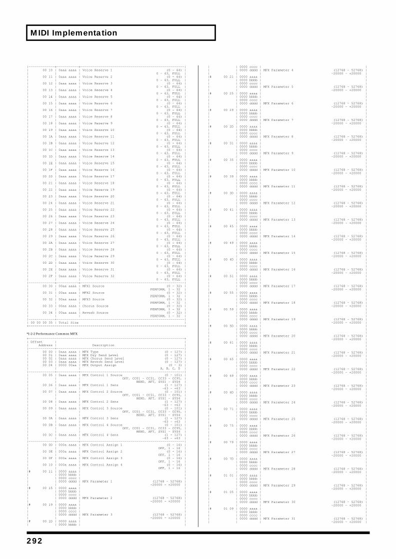
MIDI Implementation
|—————————————+———————————+————————————————————————————————————————————————————|| 00 10 | 0aaa aaaa | Voice Reserve 1 (0 - 64) || | | 0 - 63, FULL || 00 11 | 0aaa aaaa | Voice Reserve 2 (0 - 64) || | | 0 - 63, FULL || 00 12 | 0aaa aaaa | Voice Reserve 3 (0 - 64) || | | 0 - 63, FULL || 00 13 | 0aaa aaaa | Voice Reserve 4 (0 - 64) || | | 0 - 63, FULL || 00 14 | 0aaa aaaa | Voice Reserve 5 (0 - 64) || | | 0 - 63, FULL || 00 15 | 0aaa aaaa | Voice Reserve 6 (0 - 64) || | | 0 - 63, FULL || 00 16 | 0aaa aaaa | Voice Reserve 7 (0 - 64) || | | 0 - 63, FULL || 00 17 | 0aaa aaaa | Voice Reserve 8 (0 - 64) || | | 0 - 63, FULL || 00 18 | 0aaa aaaa | Voice Reserve 9 (0 - 64) || | | 0 - 63, FULL || 00 19 | 0aaa aaaa | Voice Reserve 10 (0 - 64) || | | 0 - 63, FULL || 00 1A | 0aaa aaaa | Voice Reserve 11 (0 - 64) || | | 0 - 63, FULL || 00 1B | 0aaa aaaa | Voice Reserve 12 (0 - 64) || | | 0 - 63, FULL || 00 1C | 0aaa aaaa | Voice Reserve 13 (0 - 64) || | | 0 - 63, FULL || 00 1D | 0aaa aaaa | Voice Reserve 14 (0 - 64) || | | 0 - 63, FULL || 00 1E | 0aaa aaaa | Voice Reserve 15 (0 - 64) || | | 0 - 63, FULL || 00 1F | 0aaa aaaa | Voice Reserve 16 (0 - 64) || | | 0 - 63, FULL || 00 20 | 0aaa aaaa | Voice Reserve 17 (0 - 64) || | | 0 - 63, FULL || 00 21 | 0aaa aaaa | Voice Reserve 18 (0 - 64) || | | 0 - 63, FULL || 00 22 | 0aaa aaaa | Voice Reserve 19 (0 - 64) || | | 0 - 63, FULL || 00 23 | 0aaa aaaa | Voice Reserve 20 (0 - 64) || | | 0 - 63, FULL || 00 24 | 0aaa aaaa | Voice Reserve 21 (0 - 64) || | | 0 - 63, FULL || 00 25 | 0aaa aaaa | Voice Reserve 22 (0 - 64) || | | 0 - 63, FULL || 00 26 | 0aaa aaaa | Voice Reserve 23 (0 - 64) || | | 0 - 63, FULL || 00 27 | 0aaa aaaa | Voice Reserve 24 (0 - 64) || | | 0 - 63, FULL || 00 28 | 0aaa aaaa | Voice Reserve 25 (0 - 64) || | | 0 - 63, FULL || 00 29 | 0aaa aaaa | Voice Reserve 26 (0 - 64) || | | 0 - 63, FULL || 00 2A | 0aaa aaaa | Voice Reserve 27 (0 - 64) || | | 0 - 63, FULL || 00 2B | 0aaa aaaa | Voice Reserve 28 (0 - 64) || | | 0 - 63, FULL || 00 2C | 0aaa aaaa | Voice Reserve 29 (0 - 64) || | | 0 - 63, FULL || 00 2D | 0aaa aaaa | Voice Reserve 30 (0 - 64) || | | 0 - 63, FULL || 00 2E | 0aaa aaaa | Voice Reserve 31 (0 - 64) || | | 0 - 63, FULL || 00 2F | 0aaa aaaa | Voice Reserve 32 (0 - 64) || | | 0 - 63, FULL ||—————————————+———————————+————————————————————————————————————————————————————|| 00 30 | 00aa aaaa | MFX1 Source (0 - 32) || | | PERFORM, 1 - 32 || 00 31 | 00aa aaaa | MFX2 Source (0 - 32) || | | PERFORM, 1 - 32 || 00 32 | 00aa aaaa | MFX3 Source (0 - 32) || | | PERFORM, 1 - 32 || 00 33 | 00aa aaaa | Chorus Source (0 - 32) || | | PERFORM, 1 - 32 || 00 34 | 00aa aaaa | Reverb Source (0 - 32) || | | PERFORM, 1 - 32 ||—————————————+————————————————————————————————————————————————————————————————|| 00 00 00 35 | Total Size |+——————————————————————————————————————————————————————————————————————————————+
*1-2-2 Performance Common MFX+——————————————————————————————————————————————————————————————————————————————+| Offset | || Address | Description ||—————————————+————————————————————————————————————————————————————————————————|| 00 00 | 0aaa aaaa | MFX Type (0 - 127) || 00 01 | 0aaa aaaa | MFX Dry Send Level (0 - 127) || 00 02 | 0aaa aaaa | MFX Chorus Send Level (0 - 127) || 00 03 | 0aaa aaaa | MFX Reverb Send Level (0 - 127) || 00 04 | 0000 00aa | MFX Output Assign (0 - 3) || | | A, B, C, D ||—————————————+———————————+————————————————————————————————————————————————————|| 00 05 | 0aaa aaaa | MFX Control 1 Source (0 - 101) || | | OFF, CC01 - CC31, CC33 - CC95, || | | BEND, AFT, SYS1 - SYS4 || 00 06 | 0aaa aaaa | MFX Control 1 Sens (1 - 127) || | | -63 - +63 || 00 07 | 0aaa aaaa | MFX Control 2 Source (0 - 101) || | | OFF, CC01 - CC31, CC33 - CC95, || | | BEND, AFT, SYS1 - SYS4 || 00 08 | 0aaa aaaa | MFX Control 2 Sens (1 - 127) || | | -63 - +63 || 00 09 | 0aaa aaaa | MFX Control 3 Source (0 - 101) || | | OFF, CC01 - CC31, CC33 - CC95, || | | BEND, AFT, SYS1 - SYS4 || 00 0A | 0aaa aaaa | MFX Control 3 Sens (1 - 127) || | | -63 - +63 || 00 0B | 0aaa aaaa | MFX Control 4 Source (0 - 101) || | | OFF, CC01 - CC31, CC33 - CC95, || | | BEND, AFT, SYS1 - SYS4 || 00 0C | 0aaa aaaa | MFX Control 4 Sens (1 - 127) || | | -63 - +63 ||—————————————+———————————+————————————————————————————————————————————————————|| 00 0D | 000a aaaa | MFX Control Assign 1 (0 - 16) || | | OFF, 1 - 16 || 00 0E | 000a aaaa | MFX Control Assign 2 (0 - 16) || | | OFF, 1 - 16 || 00 0F | 000a aaaa | MFX Control Assign 3 (0 - 16) || | | OFF, 1 - 16 || 00 10 | 000a aaaa | MFX Control Assign 4 (0 - 16) || | | OFF, 1 - 16 ||# 00 11 | 0000 aaaa | || | 0000 bbbb | || | 0000 cccc | || | 0000 dddd | MFX Parameter 1 (12768 - 52768) || | | -20000 - +20000 ||# 00 15 | 0000 aaaa | || | 0000 bbbb | || | 0000 cccc | || | 0000 dddd | MFX Parameter 2 (12768 - 52768) || | | -20000 - +20000 ||# 00 19 | 0000 aaaa | || | 0000 bbbb | || | 0000 cccc | || | 0000 dddd | MFX Parameter 3 (12768 - 52768) || | | -20000 - +20000 ||# 00 1D | 0000 aaaa | || | 0000 bbbb | |
| | 0000 cccc | || | 0000 dddd | MFX Parameter 4 (12768 - 52768) || | | -20000 - +20000 ||# 00 21 | 0000 aaaa | || | 0000 bbbb | || | 0000 cccc | || | 0000 dddd | MFX Parameter 5 (12768 - 52768) || | | -20000 - +20000 ||# 00 25 | 0000 aaaa | || | 0000 bbbb | || | 0000 cccc | || | 0000 dddd | MFX Parameter 6 (12768 - 52768) || | | -20000 - +20000 ||# 00 29 | 0000 aaaa | || | 0000 bbbb | || | 0000 cccc | || | 0000 dddd | MFX Parameter 7 (12768 - 52768) || | | -20000 - +20000 ||# 00 2D | 0000 aaaa | || | 0000 bbbb | || | 0000 cccc | || | 0000 dddd | MFX Parameter 8 (12768 - 52768) || | | -20000 - +20000 ||# 00 31 | 0000 aaaa | || | 0000 bbbb | || | 0000 cccc | || | 0000 dddd | MFX Parameter 9 (12768 - 52768) || | | -20000 - +20000 ||# 00 35 | 0000 aaaa | || | 0000 bbbb | || | 0000 cccc | || | 0000 dddd | MFX Parameter 10 (12768 - 52768) || | | -20000 - +20000 ||# 00 39 | 0000 aaaa | || | 0000 bbbb | || | 0000 cccc | || | 0000 dddd | MFX Parameter 11 (12768 - 52768) || | | -20000 - +20000 ||# 00 3D | 0000 aaaa | || | 0000 bbbb | || | 0000 cccc | || | 0000 dddd | MFX Parameter 12 (12768 - 52768) || | | -20000 - +20000 ||# 00 41 | 0000 aaaa | || | 0000 bbbb | || | 0000 cccc | || | 0000 dddd | MFX Parameter 13 (12768 - 52768) || | | -20000 - +20000 ||# 00 45 | 0000 aaaa | || | 0000 bbbb | || | 0000 cccc | || | 0000 dddd | MFX Parameter 14 (12768 - 52768) || | | -20000 - +20000 ||# 00 49 | 0000 aaaa | || | 0000 bbbb | || | 0000 cccc | || | 0000 dddd | MFX Parameter 15 (12768 - 52768) || | | -20000 - +20000 ||# 00 4D | 0000 aaaa | || | 0000 bbbb | || | 0000 cccc | || | 0000 dddd | MFX Parameter 16 (12768 - 52768) || | | -20000 - +20000 ||# 00 51 | 0000 aaaa | || | 0000 bbbb | || | 0000 cccc | || | 0000 dddd | MFX Parameter 17 (12768 - 52768) || | | -20000 - +20000 ||# 00 55 | 0000 aaaa | || | 0000 bbbb | || | 0000 cccc | || | 0000 dddd | MFX Parameter 18 (12768 - 52768) || | | -20000 - +20000 ||# 00 59 | 0000 aaaa | || | 0000 bbbb | || | 0000 cccc | || | 0000 dddd | MFX Parameter 19 (12768 - 52768) || | | -20000 - +20000 ||# 00 5D | 0000 aaaa | || | 0000 bbbb | || | 0000 cccc | || | 0000 dddd | MFX Parameter 20 (12768 - 52768) || | | -20000 - +20000 ||# 00 61 | 0000 aaaa | || | 0000 bbbb | || | 0000 cccc | || | 0000 dddd | MFX Parameter 21 (12768 - 52768) || | | -20000 - +20000 ||# 00 65 | 0000 aaaa | || | 0000 bbbb | || | 0000 cccc | || | 0000 dddd | MFX Parameter 22 (12768 - 52768) || | | -20000 - +20000 ||# 00 69 | 0000 aaaa | || | 0000 bbbb | || | 0000 cccc | || | 0000 dddd | MFX Parameter 23 (12768 - 52768) || | | -20000 - +20000 ||# 00 6D | 0000 aaaa | || | 0000 bbbb | || | 0000 cccc | || | 0000 dddd | MFX Parameter 24 (12768 - 52768) || | | -20000 - +20000 ||# 00 71 | 0000 aaaa | || | 0000 bbbb | || | 0000 cccc | || | 0000 dddd | MFX Parameter 25 (12768 - 52768) || | | -20000 - +20000 ||# 00 75 | 0000 aaaa | || | 0000 bbbb | || | 0000 cccc | || | 0000 dddd | MFX Parameter 26 (12768 - 52768) || | | -20000 - +20000 ||# 00 79 | 0000 aaaa | || | 0000 bbbb | || | 0000 cccc | || | 0000 dddd | MFX Parameter 27 (12768 - 52768) || | | -20000 - +20000 ||# 00 7D | 0000 aaaa | || | 0000 bbbb | || | 0000 cccc | || | 0000 dddd | MFX Parameter 28 (12768 - 52768) || | | -20000 - +20000 ||# 01 01 | 0000 aaaa | || | 0000 bbbb | || | 0000 cccc | || | 0000 dddd | MFX Parameter 29 (12768 - 52768) || | | -20000 - +20000 ||# 01 05 | 0000 aaaa | || | 0000 bbbb | || | 0000 cccc | || | 0000 dddd | MFX Parameter 30 (12768 - 52768) || | | -20000 - +20000 ||# 01 09 | 0000 aaaa | || | 0000 bbbb | || | 0000 cccc | || | 0000 dddd | MFX Parameter 31 (12768 - 52768) || | | -20000 - +20000 |
292

MIDI Implementation
Appen
dices
|# 01 0D | 0000 aaaa | || | 0000 bbbb | || | 0000 cccc | || | 0000 dddd | MFX Parameter 32 (12768 - 52768) || | | -20000 - +20000 ||—————————————+————————————————————————————————————————————————————————————————|| 00 00 01 11 | Total Size |+——————————————————————————————————————————————————————————————————————————————+
*1-2-3 Performance Common Chorus+——————————————————————————————————————————————————————————————————————————————+| Offset | || Address | Description ||—————————————+————————————————————————————————————————————————————————————————|| 00 00 | 0000 aaaa | Chorus Type (0 - 2) || 00 01 | 0aaa aaaa | Chorus Level (0 - 127) || 00 02 | 0000 00aa | Chorus Output Assign (0 - 3) || | | A, B, C, D || 00 03 | 0000 00aa | Chorus Output Select (0 - 2) || | | MAIN, REV, MAIN+REV ||—————————————+———————————+————————————————————————————————————————————————————||# 00 04 | 0000 aaaa | || | 0000 bbbb | || | 0000 cccc | || | 0000 dddd | Chorus Parameter 1 (12768 - 52768) || | | -20000 - +20000 ||# 00 08 | 0000 aaaa | || | 0000 bbbb | || | 0000 cccc | || | 0000 dddd | Chorus Parameter 2 (12768 - 52768) || | | -20000 - +20000 ||# 00 0C | 0000 aaaa | || | 0000 bbbb | || | 0000 cccc | || | 0000 dddd | Chorus Parameter 3 (12768 - 52768) || | | -20000 - +20000 ||# 00 10 | 0000 aaaa | || | 0000 bbbb | || | 0000 cccc | || | 0000 dddd | Chorus Parameter 4 (12768 - 52768) || | | -20000 - +20000 ||# 00 14 | 0000 aaaa | || | 0000 bbbb | || | 0000 cccc | || | 0000 dddd | Chorus Parameter 5 (12768 - 52768) || | | -20000 - +20000 ||# 00 18 | 0000 aaaa | || | 0000 bbbb | || | 0000 cccc | || | 0000 dddd | Chorus Parameter 6 (12768 - 52768) || | | -20000 - +20000 ||# 00 1C | 0000 aaaa | || | 0000 bbbb | || | 0000 cccc | || | 0000 dddd | Chorus Parameter 7 (12768 - 52768) || | | -20000 - +20000 ||# 00 20 | 0000 aaaa | || | 0000 bbbb | || | 0000 cccc | || | 0000 dddd | Chorus Parameter 8 (12768 - 52768) || | | -20000 - +20000 ||# 00 24 | 0000 aaaa | || | 0000 bbbb | || | 0000 cccc | || | 0000 dddd | Chorus Parameter 9 (12768 - 52768) || | | -20000 - +20000 ||# 00 28 | 0000 aaaa | || | 0000 bbbb | || | 0000 cccc | || | 0000 dddd | Chorus Parameter 10 (12768 - 52768) || | | -20000 - +20000 ||# 00 2C | 0000 aaaa | || | 0000 bbbb | || | 0000 cccc | || | 0000 dddd | Chorus Parameter 11 (12768 - 52768) || | | -20000 - +20000 ||# 00 30 | 0000 aaaa | || | 0000 bbbb | || | 0000 cccc | || | 0000 dddd | Chorus Parameter 12 (12768 - 52768) || | | -20000 - +20000 ||—————————————+————————————————————————————————————————————————————————————————|| 00 00 00 34 | Total Size |+——————————————————————————————————————————————————————————————————————————————+
*1-2-4 Performance Common Reverb+——————————————————————————————————————————————————————————————————————————————+| Offset | || Address | Description ||—————————————+————————————————————————————————————————————————————————————————|| 00 00 | 0000 aaaa | Reverb Type (0 - 4) || 00 01 | 0aaa aaaa | Reverb Level (0 - 127) || 00 02 | 0000 00aa | Reverb Output Assign (0 - 3) || | | A, B, C, D ||—————————————+———————————+————————————————————————————————————————————————————||# 00 03 | 0000 aaaa | || | 0000 bbbb | || | 0000 cccc | || | 0000 dddd | Reverb Parameter 1 (12768 - 52768) || | | -20000 - +20000 ||# 00 07 | 0000 aaaa | || | 0000 bbbb | || | 0000 cccc | || | 0000 dddd | Reverb Parameter 2 (12768 - 52768) || | | -20000 - +20000 ||# 00 0B | 0000 aaaa | || | 0000 bbbb | || | 0000 cccc | || | 0000 dddd | Reverb Parameter 3 (12768 - 52768) || | | -20000 - +20000 ||# 00 0F | 0000 aaaa | || | 0000 bbbb | || | 0000 cccc | || | 0000 dddd | Reverb Parameter 4 (12768 - 52768) || | | -20000 - +20000 ||# 00 13 | 0000 aaaa | || | 0000 bbbb | || | 0000 cccc | || | 0000 dddd | Reverb Parameter 5 (12768 - 52768) || | | -20000 - +20000 ||# 00 17 | 0000 aaaa | || | 0000 bbbb | || | 0000 cccc | || | 0000 dddd | Reverb Parameter 6 (12768 - 52768) || | | -20000 - +20000 ||# 00 1B | 0000 aaaa | || | 0000 bbbb | || | 0000 cccc | || | 0000 dddd | Reverb Parameter 7 (12768 - 52768) || | | -20000 - +20000 ||# 00 1F | 0000 aaaa | || | 0000 bbbb | || | 0000 cccc | || | 0000 dddd | Reverb Parameter 8 (12768 - 52768) || | | -20000 - +20000 ||# 00 23 | 0000 aaaa | || | 0000 bbbb | |
| | 0000 cccc | || | 0000 dddd | Reverb Parameter 9 (12768 - 52768) || | | -20000 - +20000 ||# 00 27 | 0000 aaaa | || | 0000 bbbb | || | 0000 cccc | || | 0000 dddd | Reverb Parameter 10 (12768 - 52768) || | | -20000 - +20000 ||# 00 2B | 0000 aaaa | || | 0000 bbbb | || | 0000 cccc | || | 0000 dddd | Reverb Parameter 11 (12768 - 52768) || | | -20000 - +20000 ||# 00 2F | 0000 aaaa | || | 0000 bbbb | || | 0000 cccc | || | 0000 dddd | Reverb Parameter 12 (12768 - 52768) || | | -20000 - +20000 ||# 00 33 | 0000 aaaa | || | 0000 bbbb | || | 0000 cccc | || | 0000 dddd | Reverb Parameter 13 (12768 - 52768) || | | -20000 - +20000 ||# 00 37 | 0000 aaaa | || | 0000 bbbb | || | 0000 cccc | || | 0000 dddd | Reverb Parameter 14 (12768 - 52768) || | | -20000 - +20000 ||# 00 3B | 0000 aaaa | || | 0000 bbbb | || | 0000 cccc | || | 0000 dddd | Reverb Parameter 15 (12768 - 52768) || | | -20000 - +20000 ||# 00 3F | 0000 aaaa | || | 0000 bbbb | || | 0000 cccc | || | 0000 dddd | Reverb Parameter 16 (12768 - 52768) || | | -20000 - +20000 ||# 00 43 | 0000 aaaa | || | 0000 bbbb | || | 0000 cccc | || | 0000 dddd | Reverb Parameter 17 (12768 - 52768) || | | -20000 - +20000 ||# 00 47 | 0000 aaaa | || | 0000 bbbb | || | 0000 cccc | || | 0000 dddd | Reverb Parameter 18 (12768 - 52768) || | | -20000 - +20000 ||# 00 4B | 0000 aaaa | || | 0000 bbbb | || | 0000 cccc | || | 0000 dddd | Reverb Parameter 19 (12768 - 52768) || | | -20000 - +20000 ||# 00 4F | 0000 aaaa | || | 0000 bbbb | || | 0000 cccc | || | 0000 dddd | Reverb Parameter 20 (12768 - 52768) || | | -20000 - +20000 ||—————————————+————————————————————————————————————————————————————————————————|| 00 00 00 53 | Total Size |+——————————————————————————————————————————————————————————————————————————————+
*1-2-5 Performance MIDI+——————————————————————————————————————————————————————————————————————————————+| Offset | || Address | Description ||—————————————+————————————————————————————————————————————————————————————————|| 00 00 | 0000 000a | Receive Program Change (0 - 1) || | | OFF, ON || 00 01 | 0000 000a | Receive Bank Select (0 - 1) || | | OFF, ON || 00 02 | 0000 000a | Receive Bender (0 - 1) || | | OFF, ON || 00 03 | 0000 000a | Receive Polyphonic Key Pressure (0 - 1) || | | OFF, ON || 00 04 | 0000 000a | Receive Channel Pressure (0 - 1) || | | OFF, ON || 00 05 | 0000 000a | Receive Modulation (0 - 1) || | | OFF, ON || 00 06 | 0000 000a | Receive Volume (0 - 1) || | | OFF, ON || 00 07 | 0000 000a | Receive Pan (0 - 1) || | | OFF, ON || 00 08 | 0000 000a | Receive Expression (0 - 1) || | | OFF, ON || 00 09 | 0000 000a | Receive Hold-1 (0 - 1) || | | OFF, ON ||—————————————+———————————+————————————————————————————————————————————————————|| 00 0A | 0000 000a | Phase Lock (0 - 1) || | | OFF, ON || 00 0B | 0000 0aaa | Velocity Curve Type (0 - 4) || | | OFF, 1 - 4 ||—————————————+————————————————————————————————————————————————————————————————|| 00 00 00 0C | Total Size |+——————————————————————————————————————————————————————————————————————————————+
*1-2-6 Performance Part+——————————————————————————————————————————————————————————————————————————————+| Offset | || Address | Description ||—————————————+————————————————————————————————————————————————————————————————|| 00 00 | 0000 aaaa | Receive Channel (0 - 15) || | | 1 - 16 || 00 01 | 0000 000a | Receive Switch (0 - 1) || | | OFF, ON || 00 02 | 0000 000a | Receive MIDI1 (0 - 1) || | | OFF, ON || 00 03 | 0000 000a | Receive MIDI2 (0 - 1) || | | OFF, ON ||—————————————+———————————+————————————————————————————————————————————————————|| 00 04 | 0aaa aaaa | Patch Bank Select MSB (CC# 0) (0 - 127) || 00 05 | 0aaa aaaa | Patch Bank Select LSB (CC# 32) (0 - 127) || 00 06 | 0aaa aaaa | Patch Program Number (PC) (0 - 127) ||—————————————+———————————+————————————————————————————————————————————————————|| 00 07 | 0aaa aaaa | Part Level (CC# 7) (0 - 127) || 00 08 | 0aaa aaaa | Part Pan (CC# 10) (0 - 127) || | | L64 - 63R || 00 09 | 0aaa aaaa | Part Coarse Tune (RPN# 2) (16 - 112) || | | -48 - +48 || 00 0A | 0aaa aaaa | Part Fine Tune (RPN# 1) (14 - 114) || | | -50 - +50 || 00 0B | 0000 00aa | Part Mono/Poly (MONO ON/POLY ON) (0 - 2) || | | MONO, POLY, PATCH || 00 0C | 0000 00aa | Part Legato Switch (CC# 68) (0 - 2) || | | OFF, ON, PATCH || 00 0D | 000a aaaa | Part Pitch Bend Range (RPN# 0) (0 - 25) || | | 0 - 24, PATCH || 00 0E | 0000 00aa | Part Portamento Switch (CC# 65) (0 - 2) || | | OFF, ON, PATCH ||# 00 0F | 0000 aaaa | || | 0000 bbbb | Part Portamento Time (CC# 5) (0 - 128) || | | 0 - 127, PATCH || 00 11 | 0aaa aaaa | Part Cutoff Offset (CC# 74) (0 - 127) || | | -64 - +63 || 00 12 | 0aaa aaaa | Part Resonance Offset (CC# 71) (0 - 127) || | | -64 - +63 || 00 13 | 0aaa aaaa | Part Attack Time Offset (CC# 73) (0 - 127) |
293
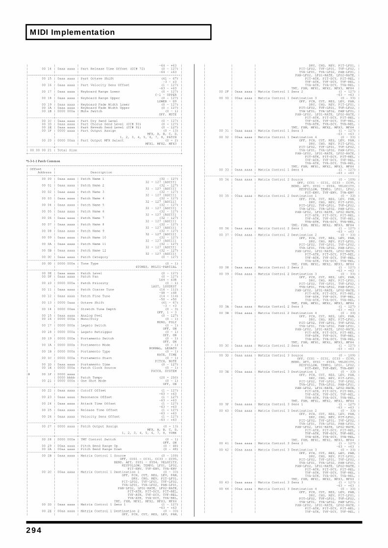
MIDI Implementation
| | | -64 - +63 || 00 14 | 0aaa aaaa | Part Release Time Offset (CC# 72) (0 - 127) || | | -64 - +63 ||—————————————+———————————+————————————————————————————————————————————————————|| 00 15 | 0aaa aaaa | Part Octave Shift (61 - 67) || | | -3 - +3 || 00 16 | 0aaa aaaa | Part Velocity Sens Offset (1 - 127) || | | -63 - +63 || 00 17 | 0aaa aaaa | Keyboard Range Lower (0 - 127) || | | C-1 - UPPER || 00 18 | 0aaa aaaa | Keyboard Range Upper (0 - 127) || | | LOWER - G9 || 00 19 | 0aaa aaaa | Keyboard Fade Width Lower (0 - 127) || 00 1A | 0aaa aaaa | Keyboard Fade Width Upper (0 - 127) || 00 1B | 0000 000a | Mute Switch (0 - 1) || | | OFF, MUTE ||—————————————+———————————+————————————————————————————————————————————————————|| 00 1C | 0aaa aaaa | Part Dry Send Level (0 - 127) || 00 1D | 0aaa aaaa | Part Chorus Send Level (CC# 93) (0 - 127) || 00 1E | 0aaa aaaa | Part Reverb Send Level (CC# 91) (0 - 127) || 00 1F | 0000 aaaa | Part Output Assign (0 - 13) || | | MFX, A, B, C, D, || | | 1, 2, 3, 4, 5, 6, 7, 8, PATCH || 00 20 | 0000 00aa | Part Output MFX Select (0 - 2) || | | MFX1, MFX2, MFX3 ||—————————————+————————————————————————————————————————————————————————————————|| 00 00 00 21 | Total Size |+——————————————————————————————————————————————————————————————————————————————+
*1-3-1-1 Patch Common+——————————————————————————————————————————————————————————————————————————————+| Offset | || Address | Description ||—————————————+————————————————————————————————————————————————————————————————|| 00 00 | 0aaa aaaa | Patch Name 1 (32 - 127) || | | 32 - 127 [ASCII] || 00 01 | 0aaa aaaa | Patch Name 2 (32 - 127) || | | 32 - 127 [ASCII] || 00 02 | 0aaa aaaa | Patch Name 3 (32 - 127) || | | 32 - 127 [ASCII] || 00 03 | 0aaa aaaa | Patch Name 4 (32 - 127) || | | 32 - 127 [ASCII] || 00 04 | 0aaa aaaa | Patch Name 5 (32 - 127) || | | 32 - 127 [ASCII] || 00 05 | 0aaa aaaa | Patch Name 6 (32 - 127) || | | 32 - 127 [ASCII] || 00 06 | 0aaa aaaa | Patch Name 7 (32 - 127) || | | 32 - 127 [ASCII] || 00 07 | 0aaa aaaa | Patch Name 8 (32 - 127) || | | 32 - 127 [ASCII] || 00 08 | 0aaa aaaa | Patch Name 9 (32 - 127) || | | 32 - 127 [ASCII] || 00 09 | 0aaa aaaa | Patch Name 10 (32 - 127) || | | 32 - 127 [ASCII] || 00 0A | 0aaa aaaa | Patch Name 11 (32 - 127) || | | 32 - 127 [ASCII] || 00 0B | 0aaa aaaa | Patch Name 12 (32 - 127) || | | 32 - 127 [ASCII] || 00 0C | 0aaa aaaa | Patch Category (0 - 127) ||—————————————+———————————+————————————————————————————————————————————————————|| 00 0D | 0000 000a | Tone Type (0 - 1) || | | 4TONES, MULTI-PARTIAL ||—————————————+———————————+————————————————————————————————————————————————————|| 00 0E | 0aaa aaaa | Patch Level (0 - 127) || 00 0F | 0aaa aaaa | Patch Pan (0 - 127) || | | L64 - 63R || 00 10 | 0000 000a | Patch Priority (0 - 1) || | | LAST, LOUDEST || 00 11 | 0aaa aaaa | Patch Coarse Tune (16 - 112) || | | -48 - +48 || 00 12 | 0aaa aaaa | Patch Fine Tune (14 - 114) || | | -50 - +50 || 00 13 | 0000 0aaa | Octave Shift (61 - 67) || | | -3 - +3 || 00 14 | 0000 00aa | Stretch Tune Depth (0 - 3) || | | OFF, 1 - 3 || 00 15 | 0aaa aaaa | Analog Feel (0 - 127) || 00 16 | 0000 000a | Mono/Poly (0 - 1) || | | MONO, POLY || 00 17 | 0000 000a | Legato Switch (0 - 1) || | | OFF, ON || 00 18 | 0000 000a | Legato Retrigger (0 - 1) || | | OFF, ON || 00 19 | 0000 000a | Portamento Switch (0 - 1) || | | OFF, ON || 00 1A | 0000 000a | Portamento Mode (0 - 1) || | | NORMAL, LEGATO || 00 1B | 0000 000a | Portamento Type (0 - 1) || | | RATE, TIME || 00 1C | 0000 000a | Portamento Start (0 - 1) || | | PITCH, NOTE || 00 1D | 0aaa aaaa | Portamento Time (0 - 127) || 00 1E | 0000 000a | Patch Clock Source (0 - 1) || | | PATCH, SYSTEM ||# 00 1F | 0000 aaaa | || | 0000 bbbb | Patch Tempo (20 - 250) || 00 21 | 0000 000a | One Shot Mode (0 - 1) || | | OFF, ON ||—————————————+———————————+————————————————————————————————————————————————————|| 00 22 | 0aaa aaaa | Cutoff Offset (1 - 127) || | | -63 - +63 || 00 23 | 0aaa aaaa | Resonance Offset (1 - 127) || | | -63 - +63 || 00 24 | 0aaa aaaa | Attack Time Offset (1 - 127) || | | -63 - +63 || 00 25 | 0aaa aaaa | Release Time Offset (1 - 127) || | | -63 - +63 || 00 26 | 0aaa aaaa | Velocity Sens Offset (1 - 127) || | | -63 - +63 ||—————————————+———————————+————————————————————————————————————————————————————|| 00 27 | 0000 aaaa | Patch Output Assign (0 - 13) || | | MFX, A, B, C, D, || | | 1, 2, 3, 4, 5, 6, 7, 8, TONE ||—————————————+———————————+————————————————————————————————————————————————————|| 00 28 | 0000 000a | TMT Control Switch (0 - 1) || | | OFF, ON || 00 29 | 00aa aaaa | Pitch Bend Range Up (0 - 48) || 00 2A | 00aa aaaa | Pitch Bend Range Down (0 - 48) ||—————————————+———————————+————————————————————————————————————————————————————|| 00 2B | 0aaa aaaa | Matrix Control 1 Source (0 - 109) || | | OFF, CC01 - CC31, CC33 - CC95, || | | BEND, AFT, SYS1 - SYS4, VELOCITY, || | | KEYFOLLOW, TEMPO, LFO1, LFO2, || | | PIT-ENV, TVF-ENV, TVA-ENV || 00 2C | 00aa aaaa | Matrix Control 1 Destination 1 (0 - 33) || | | OFF, PCH, CUT, RES, LEV, PAN, || | | DRY, CHO, REV, PIT-LFO1, || | | PIT-LFO2, TVF-LFO1, TVF-LFO2, || | | TVA-LFO1, TVA-LFO2, PAN-LFO1, || | | PAN-LFO2, LFO1-RATE, LFO2-RATE, || | | PIT-ATK, PIT-DCY, PIT-REL, || | | TVF-ATK, TVF-DCY, TVF-REL, || | | TVA-ATK, TVA-DCY, TVA-REL, || | | TMT, FXM, MFX1, MFX2, MFX3, MFX4 || 00 2D | 0aaa aaaa | Matrix Control 1 Sens 1 (1 - 127) || | | -63 - +63 || 00 2E | 00aa aaaa | Matrix Control 1 Destination 2 (0 - 33) || | | OFF, PCH, CUT, RES, LEV, PAN, |
| | | DRY, CHO, REV, PIT-LFO1, || | | PIT-LFO2, TVF-LFO1, TVF-LFO2, || | | TVA-LFO1, TVA-LFO2, PAN-LFO1, || | | PAN-LFO2, LFO1-RATE, LFO2-RATE, || | | PIT-ATK, PIT-DCY, PIT-REL, || | | TVF-ATK, TVF-DCY, TVF-REL, || | | TVA-ATK, TVA-DCY, TVA-REL, || | | TMT, FXM, MFX1, MFX2, MFX3, MFX4 || 00 2F | 0aaa aaaa | Matrix Control 1 Sens 2 (1 - 127) || | | -63 - +63 || 00 30 | 00aa aaaa | Matrix Control 1 Destination 3 (0 - 33) || | | OFF, PCH, CUT, RES, LEV, PAN, || | | DRY, CHO, REV, PIT-LFO1, || | | PIT-LFO2, TVF-LFO1, TVF-LFO2, || | | TVA-LFO1, TVA-LFO2, PAN-LFO1, || | | PAN-LFO2, LFO1-RATE, LFO2-RATE, || | | PIT-ATK, PIT-DCY, PIT-REL, || | | TVF-ATK, TVF-DCY, TVF-REL, || | | TVA-ATK, TVA-DCY, TVA-REL, || | | TMT, FXM, MFX1, MFX2, MFX3, MFX4 || 00 31 | 0aaa aaaa | Matrix Control 1 Sens 3 (1 - 127) || | | -63 - +63 || 00 32 | 00aa aaaa | Matrix Control 1 Destination 4 (0 - 33) || | | OFF, PCH, CUT, RES, LEV, PAN, || | | DRY, CHO, REV, PIT-LFO1, || | | PIT-LFO2, TVF-LFO1, TVF-LFO2, || | | TVA-LFO1, TVA-LFO2, PAN-LFO1, || | | PAN-LFO2, LFO1-RATE, LFO2-RATE, || | | PIT-ATK, PIT-DCY, PIT-REL, || | | TVF-ATK, TVF-DCY, TVF-REL, || | | TVA-ATK, TVA-DCY, TVA-REL, || | | TMT, FXM, MFX1, MFX2, MFX3, MFX4 || 00 33 | 0aaa aaaa | Matrix Control 1 Sens 4 (1 - 127) || | | -63 - +63 ||—————————————+———————————+————————————————————————————————————————————————————|| 00 34 | 0aaa aaaa | Matrix Control 2 Source (0 - 109) || | | OFF, CC01 - CC31, CC33 - CC95, || | | BEND, AFT, SYS1 - SYS4, VELOCITY, || | | KEYFOLLOW, TEMPO, LFO1, LFO2, || | | PIT-ENV, TVF-ENV, TVA-ENV || 00 35 | 00aa aaaa | Matrix Control 2 Destination 1 (0 - 33) || | | OFF, PCH, CUT, RES, LEV, PAN, || | | DRY, CHO, REV, PIT-LFO1, || | | PIT-LFO2, TVF-LFO1, TVF-LFO2, || | | TVA-LFO1, TVA-LFO2, PAN-LFO1, || | | PAN-LFO2, LFO1-RATE, LFO2-RATE, || | | PIT-ATK, PIT-DCY, PIT-REL, || | | TVF-ATK, TVF-DCY, TVF-REL, || | | TVA-ATK, TVA-DCY, TVA-REL, || | | TMT, FXM, MFX1, MFX2, MFX3, MFX4 || 00 36 | 0aaa aaaa | Matrix Control 2 Sens 1 (1 - 127) || | | -63 - +63 || 00 37 | 00aa aaaa | Matrix Control 2 Destination 2 (0 - 33) || | | OFF, PCH, CUT, RES, LEV, PAN, || | | DRY, CHO, REV, PIT-LFO1, || | | PIT-LFO2, TVF-LFO1, TVF-LFO2, || | | TVA-LFO1, TVA-LFO2, PAN-LFO1, || | | PAN-LFO2, LFO1-RATE, LFO2-RATE, || | | PIT-ATK, PIT-DCY, PIT-REL, || | | TVF-ATK, TVF-DCY, TVF-REL, || | | TVA-ATK, TVA-DCY, TVA-REL, || | | TMT, FXM, MFX1, MFX2, MFX3, MFX4 || 00 38 | 0aaa aaaa | Matrix Control 2 Sens 2 (1 - 127) || | | -63 - +63 || 00 39 | 00aa aaaa | Matrix Control 2 Destination 3 (0 - 33) || | | OFF, PCH, CUT, RES, LEV, PAN, || | | DRY, CHO, REV, PIT-LFO1, || | | PIT-LFO2, TVF-LFO1, TVF-LFO2, || | | TVA-LFO1, TVA-LFO2, PAN-LFO1, || | | PAN-LFO2, LFO1-RATE, LFO2-RATE, || | | PIT-ATK, PIT-DCY, PIT-REL, || | | TVF-ATK, TVF-DCY, TVF-REL, || | | TVA-ATK, TVA-DCY, TVA-REL, || | | TMT, FXM, MFX1, MFX2, MFX3, MFX4 || 00 3A | 0aaa aaaa | Matrix Control 2 Sens 3 (1 - 127) || | | -63 - +63 || 00 3B | 00aa aaaa | Matrix Control 2 Destination 4 (0 - 33) || | | OFF, PCH, CUT, RES, LEV, PAN, || | | DRY, CHO, REV, PIT-LFO1, || | | PIT-LFO2, TVF-LFO1, TVF-LFO2, || | | TVA-LFO1, TVA-LFO2, PAN-LFO1, || | | PAN-LFO2, LFO1-RATE, LFO2-RATE, || | | PIT-ATK, PIT-DCY, PIT-REL, || | | TVF-ATK, TVF-DCY, TVF-REL, || | | TVA-ATK, TVA-DCY, TVA-REL, || | | TMT, FXM, MFX1, MFX2, MFX3, MFX4 || 00 3C | 0aaa aaaa | Matrix Control 2 Sens 4 (1 - 127) || | | -63 - +63 ||—————————————+———————————+————————————————————————————————————————————————————|| 00 3D | 0aaa aaaa | Matrix Control 3 Source (0 - 109) || | | OFF, CC01 - CC31, CC33 - CC95, || | | BEND, AFT, SYS1 - SYS4, VELOCITY, || | | KEYFOLLOW, TEMPO, LFO1, LFO2, || | | PIT-ENV, TVF-ENV, TVA-ENV || 00 3E | 00aa aaaa | Matrix Control 3 Destination 1 (0 - 33) || | | OFF, PCH, CUT, RES, LEV, PAN, || | | DRY, CHO, REV, PIT-LFO1, || | | PIT-LFO2, TVF-LFO1, TVF-LFO2, || | | TVA-LFO1, TVA-LFO2, PAN-LFO1, || | | PAN-LFO2, LFO1-RATE, LFO2-RATE, || | | PIT-ATK, PIT-DCY, PIT-REL, || | | TVF-ATK, TVF-DCY, TVF-REL, || | | TVA-ATK, TVA-DCY, TVA-REL, || | | TMT, FXM, MFX1, MFX2, MFX3, MFX4 || 00 3F | 0aaa aaaa | Matrix Control 3 Sens 1 (1 - 127) || | | -63 - +63 || 00 40 | 00aa aaaa | Matrix Control 3 Destination 2 (0 - 33) || | | OFF, PCH, CUT, RES, LEV, PAN, || | | DRY, CHO, REV, PIT-LFO1, || | | PIT-LFO2, TVF-LFO1, TVF-LFO2, || | | TVA-LFO1, TVA-LFO2, PAN-LFO1, || | | PAN-LFO2, LFO1-RATE, LFO2-RATE, || | | PIT-ATK, PIT-DCY, PIT-REL, || | | TVF-ATK, TVF-DCY, TVF-REL, || | | TVA-ATK, TVA-DCY, TVA-REL, || | | TMT, FXM, MFX1, MFX2, MFX3, MFX4 || 00 41 | 0aaa aaaa | Matrix Control 3 Sens 2 (1 - 127) || | | -63 - +63 || 00 42 | 00aa aaaa | Matrix Control 3 Destination 3 (0 - 33) || | | OFF, PCH, CUT, RES, LEV, PAN, || | | DRY, CHO, REV, PIT-LFO1, || | | PIT-LFO2, TVF-LFO1, TVF-LFO2, || | | TVA-LFO1, TVA-LFO2, PAN-LFO1, || | | PAN-LFO2, LFO1-RATE, LFO2-RATE, || | | PIT-ATK, PIT-DCY, PIT-REL, || | | TVF-ATK, TVF-DCY, TVF-REL, || | | TVA-ATK, TVA-DCY, TVA-REL, || | | TMT, FXM, MFX1, MFX2, MFX3, MFX4 || 00 43 | 0aaa aaaa | Matrix Control 3 Sens 3 (1 - 127) || | | -63 - +63 || 00 44 | 00aa aaaa | Matrix Control 3 Destination 4 (0 - 33) || | | OFF, PCH, CUT, RES, LEV, PAN, || | | DRY, CHO, REV, PIT-LFO1, || | | PIT-LFO2, TVF-LFO1, TVF-LFO2, || | | TVA-LFO1, TVA-LFO2, PAN-LFO1, || | | PAN-LFO2, LFO1-RATE, LFO2-RATE, || | | PIT-ATK, PIT-DCY, PIT-REL, || | | TVF-ATK, TVF-DCY, TVF-REL, |
294
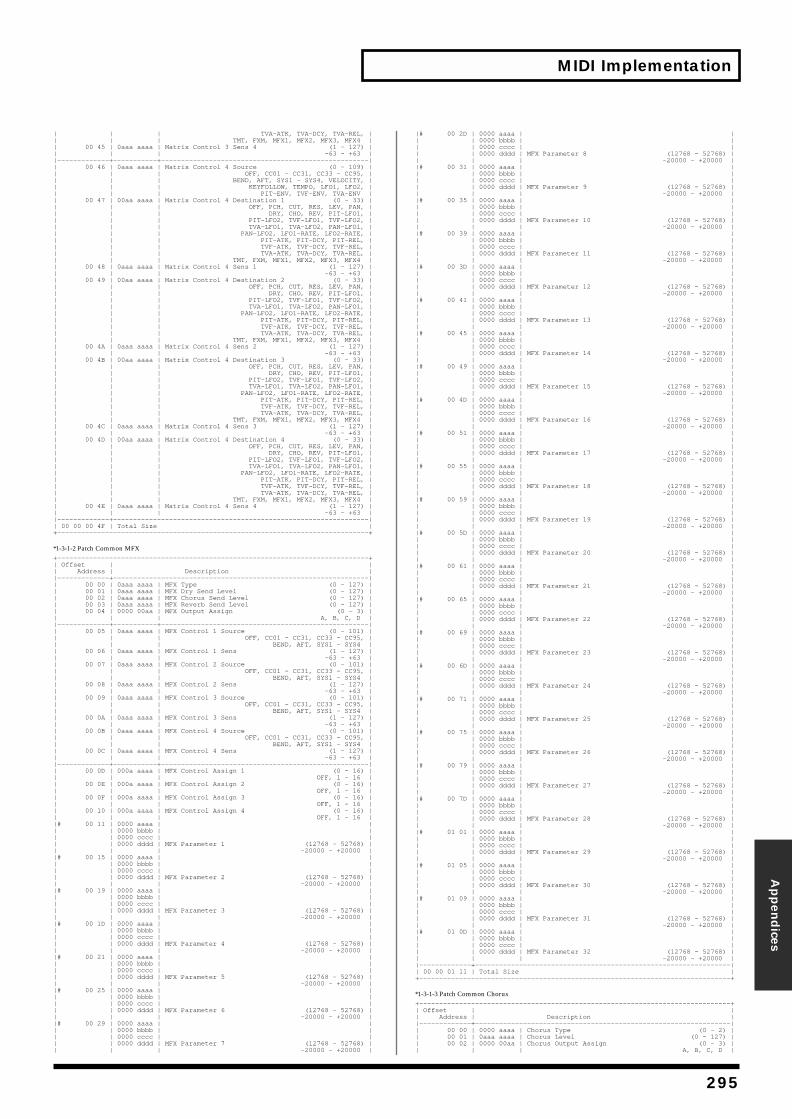
MIDI Implementation
Appen
dices
| | | TVA-ATK, TVA-DCY, TVA-REL, || | | TMT, FXM, MFX1, MFX2, MFX3, MFX4 || 00 45 | 0aaa aaaa | Matrix Control 3 Sens 4 (1 - 127) || | | -63 - +63 ||—————————————+———————————+————————————————————————————————————————————————————|| 00 46 | 0aaa aaaa | Matrix Control 4 Source (0 - 109) || | | OFF, CC01 - CC31, CC33 - CC95, || | | BEND, AFT, SYS1 - SYS4, VELOCITY, || | | KEYFOLLOW, TEMPO, LFO1, LFO2, || | | PIT-ENV, TVF-ENV, TVA-ENV || 00 47 | 00aa aaaa | Matrix Control 4 Destination 1 (0 - 33) || | | OFF, PCH, CUT, RES, LEV, PAN, || | | DRY, CHO, REV, PIT-LFO1, || | | PIT-LFO2, TVF-LFO1, TVF-LFO2, || | | TVA-LFO1, TVA-LFO2, PAN-LFO1, || | | PAN-LFO2, LFO1-RATE, LFO2-RATE, || | | PIT-ATK, PIT-DCY, PIT-REL, || | | TVF-ATK, TVF-DCY, TVF-REL, || | | TVA-ATK, TVA-DCY, TVA-REL, || | | TMT, FXM, MFX1, MFX2, MFX3, MFX4 || 00 48 | 0aaa aaaa | Matrix Control 4 Sens 1 (1 - 127) || | | -63 - +63 || 00 49 | 00aa aaaa | Matrix Control 4 Destination 2 (0 - 33) || | | OFF, PCH, CUT, RES, LEV, PAN, || | | DRY, CHO, REV, PIT-LFO1, || | | PIT-LFO2, TVF-LFO1, TVF-LFO2, || | | TVA-LFO1, TVA-LFO2, PAN-LFO1, || | | PAN-LFO2, LFO1-RATE, LFO2-RATE, || | | PIT-ATK, PIT-DCY, PIT-REL, || | | TVF-ATK, TVF-DCY, TVF-REL, || | | TVA-ATK, TVA-DCY, TVA-REL, || | | TMT, FXM, MFX1, MFX2, MFX3, MFX4 || 00 4A | 0aaa aaaa | Matrix Control 4 Sens 2 (1 - 127) || | | -63 - +63 || 00 4B | 00aa aaaa | Matrix Control 4 Destination 3 (0 - 33) || | | OFF, PCH, CUT, RES, LEV, PAN, || | | DRY, CHO, REV, PIT-LFO1, || | | PIT-LFO2, TVF-LFO1, TVF-LFO2, || | | TVA-LFO1, TVA-LFO2, PAN-LFO1, || | | PAN-LFO2, LFO1-RATE, LFO2-RATE, || | | PIT-ATK, PIT-DCY, PIT-REL, || | | TVF-ATK, TVF-DCY, TVF-REL, || | | TVA-ATK, TVA-DCY, TVA-REL, || | | TMT, FXM, MFX1, MFX2, MFX3, MFX4 || 00 4C | 0aaa aaaa | Matrix Control 4 Sens 3 (1 - 127) || | | -63 - +63 || 00 4D | 00aa aaaa | Matrix Control 4 Destination 4 (0 - 33) || | | OFF, PCH, CUT, RES, LEV, PAN, || | | DRY, CHO, REV, PIT-LFO1, || | | PIT-LFO2, TVF-LFO1, TVF-LFO2, || | | TVA-LFO1, TVA-LFO2, PAN-LFO1, || | | PAN-LFO2, LFO1-RATE, LFO2-RATE, || | | PIT-ATK, PIT-DCY, PIT-REL, || | | TVF-ATK, TVF-DCY, TVF-REL, || | | TVA-ATK, TVA-DCY, TVA-REL, || | | TMT, FXM, MFX1, MFX2, MFX3, MFX4 || 00 4E | 0aaa aaaa | Matrix Control 4 Sens 4 (1 - 127) || | | -63 - +63 ||—————————————+————————————————————————————————————————————————————————————————|| 00 00 00 4F | Total Size |+——————————————————————————————————————————————————————————————————————————————+
*1-3-1-2 Patch Common MFX+——————————————————————————————————————————————————————————————————————————————+| Offset | || Address | Description ||—————————————+————————————————————————————————————————————————————————————————|| 00 00 | 0aaa aaaa | MFX Type (0 - 127) || 00 01 | 0aaa aaaa | MFX Dry Send Level (0 - 127) || 00 02 | 0aaa aaaa | MFX Chorus Send Level (0 - 127) || 00 03 | 0aaa aaaa | MFX Reverb Send Level (0 - 127) || 00 04 | 0000 00aa | MFX Output Assign (0 - 3) || | | A, B, C, D ||—————————————+———————————+————————————————————————————————————————————————————|| 00 05 | 0aaa aaaa | MFX Control 1 Source (0 - 101) || | | OFF, CC01 - CC31, CC33 - CC95, || | | BEND, AFT, SYS1 - SYS4 || 00 06 | 0aaa aaaa | MFX Control 1 Sens (1 - 127) || | | -63 - +63 || 00 07 | 0aaa aaaa | MFX Control 2 Source (0 - 101) || | | OFF, CC01 - CC31, CC33 - CC95, || | | BEND, AFT, SYS1 - SYS4 || 00 08 | 0aaa aaaa | MFX Control 2 Sens (1 - 127) || | | -63 - +63 || 00 09 | 0aaa aaaa | MFX Control 3 Source (0 - 101) || | | OFF, CC01 - CC31, CC33 - CC95, || | | BEND, AFT, SYS1 - SYS4 || 00 0A | 0aaa aaaa | MFX Control 3 Sens (1 - 127) || | | -63 - +63 || 00 0B | 0aaa aaaa | MFX Control 4 Source (0 - 101) || | | OFF, CC01 - CC31, CC33 - CC95, || | | BEND, AFT, SYS1 - SYS4 || 00 0C | 0aaa aaaa | MFX Control 4 Sens (1 - 127) || | | -63 - +63 ||—————————————+———————————+————————————————————————————————————————————————————|| 00 0D | 000a aaaa | MFX Control Assign 1 (0 - 16) || | | OFF, 1 - 16 || 00 0E | 000a aaaa | MFX Control Assign 2 (0 - 16) || | | OFF, 1 - 16 || 00 0F | 000a aaaa | MFX Control Assign 3 (0 - 16) || | | OFF, 1 - 16 || 00 10 | 000a aaaa | MFX Control Assign 4 (0 - 16) || | | OFF, 1 - 16 ||# 00 11 | 0000 aaaa | || | 0000 bbbb | || | 0000 cccc | || | 0000 dddd | MFX Parameter 1 (12768 - 52768) || | | -20000 - +20000 ||# 00 15 | 0000 aaaa | || | 0000 bbbb | || | 0000 cccc | || | 0000 dddd | MFX Parameter 2 (12768 - 52768) || | | -20000 - +20000 ||# 00 19 | 0000 aaaa | || | 0000 bbbb | || | 0000 cccc | || | 0000 dddd | MFX Parameter 3 (12768 - 52768) || | | -20000 - +20000 ||# 00 1D | 0000 aaaa | || | 0000 bbbb | || | 0000 cccc | || | 0000 dddd | MFX Parameter 4 (12768 - 52768) || | | -20000 - +20000 ||# 00 21 | 0000 aaaa | || | 0000 bbbb | || | 0000 cccc | || | 0000 dddd | MFX Parameter 5 (12768 - 52768) || | | -20000 - +20000 ||# 00 25 | 0000 aaaa | || | 0000 bbbb | || | 0000 cccc | || | 0000 dddd | MFX Parameter 6 (12768 - 52768) || | | -20000 - +20000 ||# 00 29 | 0000 aaaa | || | 0000 bbbb | || | 0000 cccc | || | 0000 dddd | MFX Parameter 7 (12768 - 52768) || | | -20000 - +20000 |
|# 00 2D | 0000 aaaa | || | 0000 bbbb | || | 0000 cccc | || | 0000 dddd | MFX Parameter 8 (12768 - 52768) || | | -20000 - +20000 ||# 00 31 | 0000 aaaa | || | 0000 bbbb | || | 0000 cccc | || | 0000 dddd | MFX Parameter 9 (12768 - 52768) || | | -20000 - +20000 ||# 00 35 | 0000 aaaa | || | 0000 bbbb | || | 0000 cccc | || | 0000 dddd | MFX Parameter 10 (12768 - 52768) || | | -20000 - +20000 ||# 00 39 | 0000 aaaa | || | 0000 bbbb | || | 0000 cccc | || | 0000 dddd | MFX Parameter 11 (12768 - 52768) || | | -20000 - +20000 ||# 00 3D | 0000 aaaa | || | 0000 bbbb | || | 0000 cccc | || | 0000 dddd | MFX Parameter 12 (12768 - 52768) || | | -20000 - +20000 ||# 00 41 | 0000 aaaa | || | 0000 bbbb | || | 0000 cccc | || | 0000 dddd | MFX Parameter 13 (12768 - 52768) || | | -20000 - +20000 ||# 00 45 | 0000 aaaa | || | 0000 bbbb | || | 0000 cccc | || | 0000 dddd | MFX Parameter 14 (12768 - 52768) || | | -20000 - +20000 ||# 00 49 | 0000 aaaa | || | 0000 bbbb | || | 0000 cccc | || | 0000 dddd | MFX Parameter 15 (12768 - 52768) || | | -20000 - +20000 ||# 00 4D | 0000 aaaa | || | 0000 bbbb | || | 0000 cccc | || | 0000 dddd | MFX Parameter 16 (12768 - 52768) || | | -20000 - +20000 ||# 00 51 | 0000 aaaa | || | 0000 bbbb | || | 0000 cccc | || | 0000 dddd | MFX Parameter 17 (12768 - 52768) || | | -20000 - +20000 ||# 00 55 | 0000 aaaa | || | 0000 bbbb | || | 0000 cccc | || | 0000 dddd | MFX Parameter 18 (12768 - 52768) || | | -20000 - +20000 ||# 00 59 | 0000 aaaa | || | 0000 bbbb | || | 0000 cccc | || | 0000 dddd | MFX Parameter 19 (12768 - 52768) || | | -20000 - +20000 ||# 00 5D | 0000 aaaa | || | 0000 bbbb | || | 0000 cccc | || | 0000 dddd | MFX Parameter 20 (12768 - 52768) || | | -20000 - +20000 ||# 00 61 | 0000 aaaa | || | 0000 bbbb | || | 0000 cccc | || | 0000 dddd | MFX Parameter 21 (12768 - 52768) || | | -20000 - +20000 ||# 00 65 | 0000 aaaa | || | 0000 bbbb | || | 0000 cccc | || | 0000 dddd | MFX Parameter 22 (12768 - 52768) || | | -20000 - +20000 ||# 00 69 | 0000 aaaa | || | 0000 bbbb | || | 0000 cccc | || | 0000 dddd | MFX Parameter 23 (12768 - 52768) || | | -20000 - +20000 ||# 00 6D | 0000 aaaa | || | 0000 bbbb | || | 0000 cccc | || | 0000 dddd | MFX Parameter 24 (12768 - 52768) || | | -20000 - +20000 ||# 00 71 | 0000 aaaa | || | 0000 bbbb | || | 0000 cccc | || | 0000 dddd | MFX Parameter 25 (12768 - 52768) || | | -20000 - +20000 ||# 00 75 | 0000 aaaa | || | 0000 bbbb | || | 0000 cccc | || | 0000 dddd | MFX Parameter 26 (12768 - 52768) || | | -20000 - +20000 ||# 00 79 | 0000 aaaa | || | 0000 bbbb | || | 0000 cccc | || | 0000 dddd | MFX Parameter 27 (12768 - 52768) || | | -20000 - +20000 ||# 00 7D | 0000 aaaa | || | 0000 bbbb | || | 0000 cccc | || | 0000 dddd | MFX Parameter 28 (12768 - 52768) || | | -20000 - +20000 ||# 01 01 | 0000 aaaa | || | 0000 bbbb | || | 0000 cccc | || | 0000 dddd | MFX Parameter 29 (12768 - 52768) || | | -20000 - +20000 ||# 01 05 | 0000 aaaa | || | 0000 bbbb | || | 0000 cccc | || | 0000 dddd | MFX Parameter 30 (12768 - 52768) || | | -20000 - +20000 ||# 01 09 | 0000 aaaa | || | 0000 bbbb | || | 0000 cccc | || | 0000 dddd | MFX Parameter 31 (12768 - 52768) || | | -20000 - +20000 ||# 01 0D | 0000 aaaa | || | 0000 bbbb | || | 0000 cccc | || | 0000 dddd | MFX Parameter 32 (12768 - 52768) || | | -20000 - +20000 ||—————————————+————————————————————————————————————————————————————————————————|| 00 00 01 11 | Total Size |+——————————————————————————————————————————————————————————————————————————————+
*1-3-1-3 Patch Common Chorus+——————————————————————————————————————————————————————————————————————————————+| Offset | || Address | Description ||—————————————+————————————————————————————————————————————————————————————————|| 00 00 | 0000 aaaa | Chorus Type (0 - 2) || 00 01 | 0aaa aaaa | Chorus Level (0 - 127) || 00 02 | 0000 00aa | Chorus Output Assign (0 - 3) || | | A, B, C, D |
295
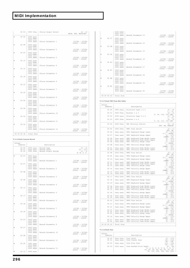
MIDI Implementation
| 00 03 | 0000 00aa | Chorus Output Select (0 - 2) || | | MAIN, REV, MAIN+REV ||—————————————+———————————+————————————————————————————————————————————————————||# 00 04 | 0000 aaaa | || | 0000 bbbb | || | 0000 cccc | || | 0000 dddd | Chorus Parameter 1 (12768 - 52768) || | | -20000 - +20000 ||# 00 08 | 0000 aaaa | || | 0000 bbbb | || | 0000 cccc | || | 0000 dddd | Chorus Parameter 2 (12768 - 52768) || | | -20000 - +20000 ||# 00 0C | 0000 aaaa | || | 0000 bbbb | || | 0000 cccc | || | 0000 dddd | Chorus Parameter 3 (12768 - 52768) || | | -20000 - +20000 ||# 00 10 | 0000 aaaa | || | 0000 bbbb | || | 0000 cccc | || | 0000 dddd | Chorus Parameter 4 (12768 - 52768) || | | -20000 - +20000 ||# 00 14 | 0000 aaaa | || | 0000 bbbb | || | 0000 cccc | || | 0000 dddd | Chorus Parameter 5 (12768 - 52768) || | | -20000 - +20000 ||# 00 18 | 0000 aaaa | || | 0000 bbbb | || | 0000 cccc | || | 0000 dddd | Chorus Parameter 6 (12768 - 52768) || | | -20000 - +20000 ||# 00 1C | 0000 aaaa | || | 0000 bbbb | || | 0000 cccc | || | 0000 dddd | Chorus Parameter 7 (12768 - 52768) || | | -20000 - +20000 ||# 00 20 | 0000 aaaa | || | 0000 bbbb | || | 0000 cccc | || | 0000 dddd | Chorus Parameter 8 (12768 - 52768) || | | -20000 - +20000 ||# 00 24 | 0000 aaaa | || | 0000 bbbb | || | 0000 cccc | || | 0000 dddd | Chorus Parameter 9 (12768 - 52768) || | | -20000 - +20000 ||# 00 28 | 0000 aaaa | || | 0000 bbbb | || | 0000 cccc | || | 0000 dddd | Chorus Parameter 10 (12768 - 52768) || | | -20000 - +20000 ||# 00 2C | 0000 aaaa | || | 0000 bbbb | || | 0000 cccc | || | 0000 dddd | Chorus Parameter 11 (12768 - 52768) || | | -20000 - +20000 ||# 00 30 | 0000 aaaa | || | 0000 bbbb | || | 0000 cccc | || | 0000 dddd | Chorus Parameter 12 (12768 - 52768) || | | -20000 - +20000 ||—————————————+————————————————————————————————————————————————————————————————|| 00 00 00 34 | Total Size |+——————————————————————————————————————————————————————————————————————————————+
*1-3-1-4 Patch Common Reverb+——————————————————————————————————————————————————————————————————————————————+| Offset | || Address | Description ||—————————————+————————————————————————————————————————————————————————————————|| 00 00 | 0000 aaaa | Reverb Type (0 - 4) || 00 01 | 0aaa aaaa | Reverb Level (0 - 127) || 00 02 | 0000 00aa | Reverb Output Assign (0 - 3) || | | A, B, C, D ||—————————————+———————————+————————————————————————————————————————————————————||# 00 03 | 0000 aaaa | || | 0000 bbbb | || | 0000 cccc | || | 0000 dddd | Reverb Parameter 1 (12768 - 52768) || | | -20000 - +20000 ||# 00 07 | 0000 aaaa | || | 0000 bbbb | || | 0000 cccc | || | 0000 dddd | Reverb Parameter 2 (12768 - 52768) || | | -20000 - +20000 ||# 00 0B | 0000 aaaa | || | 0000 bbbb | || | 0000 cccc | || | 0000 dddd | Reverb Parameter 3 (12768 - 52768) || | | -20000 - +20000 ||# 00 0F | 0000 aaaa | || | 0000 bbbb | || | 0000 cccc | || | 0000 dddd | Reverb Parameter 4 (12768 - 52768) || | | -20000 - +20000 ||# 00 13 | 0000 aaaa | || | 0000 bbbb | || | 0000 cccc | || | 0000 dddd | Reverb Parameter 5 (12768 - 52768) || | | -20000 - +20000 ||# 00 17 | 0000 aaaa | || | 0000 bbbb | || | 0000 cccc | || | 0000 dddd | Reverb Parameter 6 (12768 - 52768) || | | -20000 - +20000 ||# 00 1B | 0000 aaaa | || | 0000 bbbb | || | 0000 cccc | || | 0000 dddd | Reverb Parameter 7 (12768 - 52768) || | | -20000 - +20000 ||# 00 1F | 0000 aaaa | || | 0000 bbbb | || | 0000 cccc | || | 0000 dddd | Reverb Parameter 8 (12768 - 52768) || | | -20000 - +20000 ||# 00 23 | 0000 aaaa | || | 0000 bbbb | || | 0000 cccc | || | 0000 dddd | Reverb Parameter 9 (12768 - 52768) || | | -20000 - +20000 ||# 00 27 | 0000 aaaa | || | 0000 bbbb | || | 0000 cccc | || | 0000 dddd | Reverb Parameter 10 (12768 - 52768) || | | -20000 - +20000 ||# 00 2B | 0000 aaaa | || | 0000 bbbb | || | 0000 cccc | || | 0000 dddd | Reverb Parameter 11 (12768 - 52768) || | | -20000 - +20000 ||# 00 2F | 0000 aaaa | || | 0000 bbbb | || | 0000 cccc | || | 0000 dddd | Reverb Parameter 12 (12768 - 52768) || | | -20000 - +20000 ||# 00 33 | 0000 aaaa | |
| | 0000 bbbb | || | 0000 cccc | || | 0000 dddd | Reverb Parameter 13 (12768 - 52768) || | | -20000 - +20000 ||# 00 37 | 0000 aaaa | || | 0000 bbbb | || | 0000 cccc | || | 0000 dddd | Reverb Parameter 14 (12768 - 52768) || | | -20000 - +20000 ||# 00 3B | 0000 aaaa | || | 0000 bbbb | || | 0000 cccc | || | 0000 dddd | Reverb Parameter 15 (12768 - 52768) || | | -20000 - +20000 ||# 00 3F | 0000 aaaa | || | 0000 bbbb | || | 0000 cccc | || | 0000 dddd | Reverb Parameter 16 (12768 - 52768) || | | -20000 - +20000 ||# 00 43 | 0000 aaaa | || | 0000 bbbb | || | 0000 cccc | || | 0000 dddd | Reverb Parameter 17 (12768 - 52768) || | | -20000 - +20000 ||# 00 47 | 0000 aaaa | || | 0000 bbbb | || | 0000 cccc | || | 0000 dddd | Reverb Parameter 18 (12768 - 52768) || | | -20000 - +20000 ||# 00 4B | 0000 aaaa | || | 0000 bbbb | || | 0000 cccc | || | 0000 dddd | Reverb Parameter 19 (12768 - 52768) || | | -20000 - +20000 ||# 00 4F | 0000 aaaa | || | 0000 bbbb | || | 0000 cccc | || | 0000 dddd | Reverb Parameter 20 (12768 - 52768) || | | -20000 - +20000 ||—————————————+————————————————————————————————————————————————————————————————|| 00 00 00 53 | Total Size |+——————————————————————————————————————————————————————————————————————————————+
*1-3-1-5 Patch TMT (Tone Mix Table)+——————————————————————————————————————————————————————————————————————————————+| Offset | || Address | Description ||—————————————+————————————————————————————————————————————————————————————————|| 00 00 | 0000 aaaa | Structure Type 1 & 2 (0 - 9) || | | 1 - 10 || 00 01 | 0000 00aa | Booster 1 & 2 (0 - 3) || | | 0, +6, +12, +18 [dB] || 00 02 | 0000 aaaa | Structure Type 3 & 4 (0 - 9) || | | 1 - 10 || 00 03 | 0000 00aa | Booster 3 & 4 (0 - 3) || | | 0, +6, +12, +18 [dB] ||—————————————+———————————+————————————————————————————————————————————————————|| 00 04 | 0000 00aa | TMT Velocity Control (0 - 2) || | | OFF, ON, RANDOM ||—————————————+———————————+————————————————————————————————————————————————————|| 00 05 | 0000 000a | TMT1 Tone Switch (0 - 1) || | | OFF, ON || 00 06 | 0aaa aaaa | TMT1 Keyboard Range Lower (0 - 127) || | | C-1 - UPPER || 00 07 | 0aaa aaaa | TMT1 Keyboard Range Upper (0 - 127) || | | LOWER - G9 || 00 08 | 0aaa aaaa | TMT1 Keyboard Fade Width Lower (0 - 127) || 00 09 | 0aaa aaaa | TMT1 Keyboard Fade Width Upper (0 - 127) || 00 0A | 0aaa aaaa | TMT1 Velocity Range Lower (1 - 127) || | | 1 - UPPER || 00 0B | 0aaa aaaa | TMT1 Velocity Range Upper (1 - 127) || | | LOWER - 127 || 00 0C | 0aaa aaaa | TMT1 Velocity Fade Width Lower (0 - 127) || 00 0D | 0aaa aaaa | TMT1 Velocity Fade Width Upper (0 - 127) ||—————————————+———————————+————————————————————————————————————————————————————|| 00 0E | 0000 000a | TMT2 Tone Switch (0 - 1) || | | OFF, ON || 00 0F | 0aaa aaaa | TMT2 Keyboard Range Lower (0 - 127) || | | C-1 - UPPER || 00 10 | 0aaa aaaa | TMT2 Keyboard Range Upper (0 - 127) || | | LOWER - G9 || 00 11 | 0aaa aaaa | TMT2 Keyboard Fade Width Lower (0 - 127) || 00 12 | 0aaa aaaa | TMT2 Keyboard Fade Width Upper (0 - 127) || 00 13 | 0aaa aaaa | TMT2 Velocity Range Lower (1 - 127) || | | 1 - UPPER || 00 14 | 0aaa aaaa | TMT2 Velocity Range Upper (1 - 127) || | | LOWER - 127 || 00 15 | 0aaa aaaa | TMT2 Velocity Fade Width Lower (0 - 127) || 00 16 | 0aaa aaaa | TMT2 Velocity Fade Width Upper (0 - 127) ||—————————————+———————————+————————————————————————————————————————————————————|| 00 17 | 0000 000a | TMT3 Tone Switch (0 - 1) || | | OFF, ON || 00 18 | 0aaa aaaa | TMT3 Keyboard Range Lower (0 - 127) || | | C-1 - UPPER || 00 19 | 0aaa aaaa | TMT3 Keyboard Range Upper (0 - 127) || | | LOWER - G9 || 00 1A | 0aaa aaaa | TMT3 Keyboard Fade Width Lower (0 - 127) || 00 1B | 0aaa aaaa | TMT3 Keyboard Fade Width Upper (0 - 127) || 00 1C | 0aaa aaaa | TMT3 Velocity Range Lower (1 - 127) || | | 1 - UPPER || 00 1D | 0aaa aaaa | TMT3 Velocity Range Upper (1 - 127) || | | LOWER - 127 || 00 1E | 0aaa aaaa | TMT3 Velocity Fade Width Lower (0 - 127) || 00 1F | 0aaa aaaa | TMT3 Velocity Fade Width Upper (0 - 127) ||—————————————+———————————+————————————————————————————————————————————————————|| 00 20 | 0000 000a | TMT4 Tone Switch (0 - 1) || | | OFF, ON || 00 21 | 0aaa aaaa | TMT4 Keyboard Range Lower (0 - 127) || | | C-1 - UPPER || 00 22 | 0aaa aaaa | TMT4 Keyboard Range Upper (0 - 127) || | | LOWER - G9 || 00 23 | 0aaa aaaa | TMT4 Keyboard Fade Width Lower (0 - 127) || 00 24 | 0aaa aaaa | TMT4 Keyboard Fade Width Upper (0 - 127) || 00 25 | 0aaa aaaa | TMT4 Velocity Range Lower (1 - 127) || | | 1 - UPPER || 00 26 | 0aaa aaaa | TMT4 Velocity Range Upper (1 - 127) || | | LOWER - 127 || 00 27 | 0aaa aaaa | TMT4 Velocity Fade Width Lower (0 - 127) || 00 28 | 0aaa aaaa | TMT4 Velocity Fade Width Upper (0 - 127) ||—————————————+————————————————————————————————————————————————————————————————|| 00 00 00 29 | Total Size |+——————————————————————————————————————————————————————————————————————————————+
*1-3-1-6 Patch Tone+——————————————————————————————————————————————————————————————————————————————+| Offset | || Address | Description ||—————————————+————————————————————————————————————————————————————————————————|| 00 00 | 0aaa aaaa | Tone Level (0 - 127) || 00 01 | 0aaa aaaa | Tone Coarse Tune (16 - 112) || | | -48 - +48 || 00 02 | 0aaa aaaa | Tone Fine Tune (14 - 114) || | | -50 - +50 || 00 03 | 000a aaaa | Tone Random Pitch Depth (0 - 30) || | | 0, 1, 2, 3, 4, 5, 6, 7, 8, 9, || | | 10, 20, 30, 40, 50, 60, 70, 80, || | | 90, 100, 200, 300, 400, 500, |
296
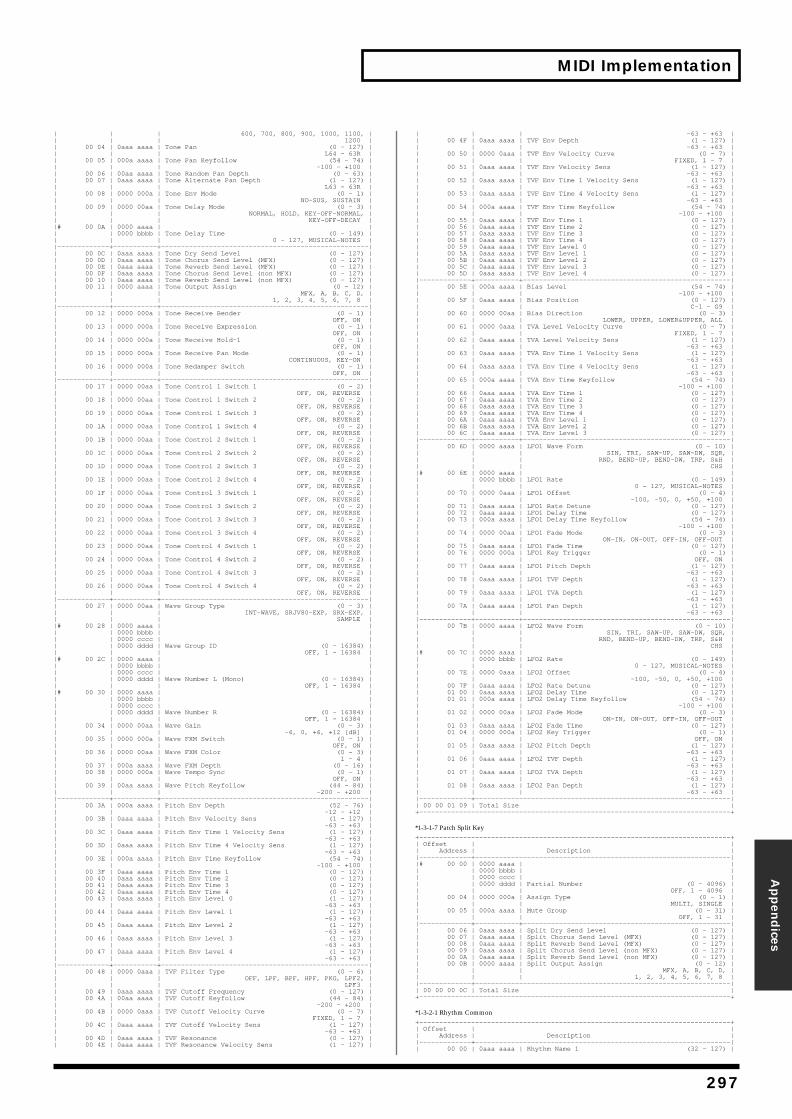
MIDI Implementation
Appen
dices
| | | 600, 700, 800, 900, 1000, 1100, || | | 1200 || 00 04 | 0aaa aaaa | Tone Pan (0 - 127) || | | L64 - 63R || 00 05 | 000a aaaa | Tone Pan Keyfollow (54 - 74) || | | -100 - +100 || 00 06 | 00aa aaaa | Tone Random Pan Depth (0 - 63) || 00 07 | 0aaa aaaa | Tone Alternate Pan Depth (1 - 127) || | | L63 - 63R || 00 08 | 0000 000a | Tone Env Mode (0 - 1) || | | NO-SUS, SUSTAIN || 00 09 | 0000 00aa | Tone Delay Mode (0 - 3) || | | NORMAL, HOLD, KEY-OFF-NORMAL, || | | KEY-OFF-DECAY ||# 00 0A | 0000 aaaa | || | 0000 bbbb | Tone Delay Time (0 - 149) || | | 0 - 127, MUSICAL-NOTES ||—————————————+———————————+————————————————————————————————————————————————————|| 00 0C | 0aaa aaaa | Tone Dry Send Level (0 - 127) || 00 0D | 0aaa aaaa | Tone Chorus Send Level (MFX) (0 - 127) || 00 0E | 0aaa aaaa | Tone Reverb Send Level (MFX) (0 - 127) || 00 0F | 0aaa aaaa | Tone Chorus Send Level (non MFX) (0 - 127) || 00 10 | 0aaa aaaa | Tone Reverb Send Level (non MFX) (0 - 127) || 00 11 | 0000 aaaa | Tone Output Assign (0 - 12) || | | MFX, A, B, C, D, || | | 1, 2, 3, 4, 5, 6, 7, 8 ||—————————————+———————————+————————————————————————————————————————————————————|| 00 12 | 0000 000a | Tone Receive Bender (0 - 1) || | | OFF, ON || 00 13 | 0000 000a | Tone Receive Expression (0 - 1) || | | OFF, ON || 00 14 | 0000 000a | Tone Receive Hold-1 (0 - 1) || | | OFF, ON || 00 15 | 0000 000a | Tone Receive Pan Mode (0 - 1) || | | CONTINUOUS, KEY-ON || 00 16 | 0000 000a | Tone Redamper Switch (0 - 1) || | | OFF, ON ||—————————————+———————————+————————————————————————————————————————————————————|| 00 17 | 0000 00aa | Tone Control 1 Switch 1 (0 - 2) || | | OFF, ON, REVERSE || 00 18 | 0000 00aa | Tone Control 1 Switch 2 (0 - 2) || | | OFF, ON, REVERSE || 00 19 | 0000 00aa | Tone Control 1 Switch 3 (0 - 2) || | | OFF, ON, REVERSE || 00 1A | 0000 00aa | Tone Control 1 Switch 4 (0 - 2) || | | OFF, ON, REVERSE || 00 1B | 0000 00aa | Tone Control 2 Switch 1 (0 - 2) || | | OFF, ON, REVERSE || 00 1C | 0000 00aa | Tone Control 2 Switch 2 (0 - 2) || | | OFF, ON, REVERSE || 00 1D | 0000 00aa | Tone Control 2 Switch 3 (0 - 2) || | | OFF, ON, REVERSE || 00 1E | 0000 00aa | Tone Control 2 Switch 4 (0 - 2) || | | OFF, ON, REVERSE || 00 1F | 0000 00aa | Tone Control 3 Switch 1 (0 - 2) || | | OFF, ON, REVERSE || 00 20 | 0000 00aa | Tone Control 3 Switch 2 (0 - 2) || | | OFF, ON, REVERSE || 00 21 | 0000 00aa | Tone Control 3 Switch 3 (0 - 2) || | | OFF, ON, REVERSE || 00 22 | 0000 00aa | Tone Control 3 Switch 4 (0 - 2) || | | OFF, ON, REVERSE || 00 23 | 0000 00aa | Tone Control 4 Switch 1 (0 - 2) || | | OFF, ON, REVERSE || 00 24 | 0000 00aa | Tone Control 4 Switch 2 (0 - 2) || | | OFF, ON, REVERSE || 00 25 | 0000 00aa | Tone Control 4 Switch 3 (0 - 2) || | | OFF, ON, REVERSE || 00 26 | 0000 00aa | Tone Control 4 Switch 4 (0 - 2) || | | OFF, ON, REVERSE ||—————————————+———————————+————————————————————————————————————————————————————|| 00 27 | 0000 00aa | Wave Group Type (0 - 3) || | | INT-WAVE, SRJV80-EXP, SRX-EXP, || | | SAMPLE ||# 00 28 | 0000 aaaa | || | 0000 bbbb | || | 0000 cccc | || | 0000 dddd | Wave Group ID (0 - 16384) || | | OFF, 1 - 16384 ||# 00 2C | 0000 aaaa | || | 0000 bbbb | || | 0000 cccc | || | 0000 dddd | Wave Number L (Mono) (0 - 16384) || | | OFF, 1 - 16384 ||# 00 30 | 0000 aaaa | || | 0000 bbbb | || | 0000 cccc | || | 0000 dddd | Wave Number R (0 - 16384) || | | OFF, 1 - 16384 || 00 34 | 0000 00aa | Wave Gain (0 - 3) || | | -6, 0, +6, +12 [dB] || 00 35 | 0000 000a | Wave FXM Switch (0 - 1) || | | OFF, ON || 00 36 | 0000 00aa | Wave FXM Color (0 - 3) || | | 1 - 4 || 00 37 | 000a aaaa | Wave FXM Depth (0 - 16) || 00 38 | 0000 000a | Wave Tempo Sync (0 - 1) || | | OFF, ON || 00 39 | 00aa aaaa | Wave Pitch Keyfollow (44 - 84) || | | -200 - +200 ||—————————————+———————————+————————————————————————————————————————————————————|| 00 3A | 000a aaaa | Pitch Env Depth (52 - 76) || | | -12 - +12 || 00 3B | 0aaa aaaa | Pitch Env Velocity Sens (1 - 127) || | | -63 - +63 || 00 3C | 0aaa aaaa | Pitch Env Time 1 Velocity Sens (1 - 127) || | | -63 - +63 || 00 3D | 0aaa aaaa | Pitch Env Time 4 Velocity Sens (1 - 127) || | | -63 - +63 || 00 3E | 000a aaaa | Pitch Env Time Keyfollow (54 - 74) || | | -100 - +100 || 00 3F | 0aaa aaaa | Pitch Env Time 1 (0 - 127) || 00 40 | 0aaa aaaa | Pitch Env Time 2 (0 - 127) || 00 41 | 0aaa aaaa | Pitch Env Time 3 (0 - 127) || 00 42 | 0aaa aaaa | Pitch Env Time 4 (0 - 127) || 00 43 | 0aaa aaaa | Pitch Env Level 0 (1 - 127) || | | -63 - +63 || 00 44 | 0aaa aaaa | Pitch Env Level 1 (1 - 127) || | | -63 - +63 || 00 45 | 0aaa aaaa | Pitch Env Level 2 (1 - 127) || | | -63 - +63 || 00 46 | 0aaa aaaa | Pitch Env Level 3 (1 - 127) || | | -63 - +63 || 00 47 | 0aaa aaaa | Pitch Env Level 4 (1 - 127) || | | -63 - +63 ||—————————————+———————————+————————————————————————————————————————————————————|| 00 48 | 0000 0aaa | TVF Filter Type (0 - 6) || | | OFF, LPF, BPF, HPF, PKG, LPF2, || | | LPF3 || 00 49 | 0aaa aaaa | TVF Cutoff Frequency (0 - 127) || 00 4A | 00aa aaaa | TVF Cutoff Keyfollow (44 - 84) || | | -200 - +200 || 00 4B | 0000 0aaa | TVF Cutoff Velocity Curve (0 - 7) || | | FIXED, 1 - 7 || 00 4C | 0aaa aaaa | TVF Cutoff Velocity Sens (1 - 127) || | | -63 - +63 || 00 4D | 0aaa aaaa | TVF Resonance (0 - 127) || 00 4E | 0aaa aaaa | TVF Resonance Velocity Sens (1 - 127) |
| | | -63 - +63 || 00 4F | 0aaa aaaa | TVF Env Depth (1 - 127) || | | -63 - +63 || 00 50 | 0000 0aaa | TVF Env Velocity Curve (0 - 7) || | | FIXED, 1 - 7 || 00 51 | 0aaa aaaa | TVF Env Velocity Sens (1 - 127) || | | -63 - +63 || 00 52 | 0aaa aaaa | TVF Env Time 1 Velocity Sens (1 - 127) || | | -63 - +63 || 00 53 | 0aaa aaaa | TVF Env Time 4 Velocity Sens (1 - 127) || | | -63 - +63 || 00 54 | 000a aaaa | TVF Env Time Keyfollow (54 - 74) || | | -100 - +100 || 00 55 | 0aaa aaaa | TVF Env Time 1 (0 - 127) || 00 56 | 0aaa aaaa | TVF Env Time 2 (0 - 127) || 00 57 | 0aaa aaaa | TVF Env Time 3 (0 - 127) || 00 58 | 0aaa aaaa | TVF Env Time 4 (0 - 127) || 00 59 | 0aaa aaaa | TVF Env Level 0 (0 - 127) || 00 5A | 0aaa aaaa | TVF Env Level 1 (0 - 127) || 00 5B | 0aaa aaaa | TVF Env Level 2 (0 - 127) || 00 5C | 0aaa aaaa | TVF Env Level 3 (0 - 127) || 00 5D | 0aaa aaaa | TVF Env Level 4 (0 - 127) ||—————————————+———————————+————————————————————————————————————————————————————|| 00 5E | 000a aaaa | Bias Level (54 - 74) || | | -100 - +100 || 00 5F | 0aaa aaaa | Bias Position (0 - 127) || | | C-1 - G9 || 00 60 | 0000 00aa | Bias Direction (0 - 3) || | | LOWER, UPPER, LOWER&UPPER, ALL || 00 61 | 0000 0aaa | TVA Level Velocity Curve (0 - 7) || | | FIXED, 1 - 7 || 00 62 | 0aaa aaaa | TVA Level Velocity Sens (1 - 127) || | | -63 - +63 || 00 63 | 0aaa aaaa | TVA Env Time 1 Velocity Sens (1 - 127) || | | -63 - +63 || 00 64 | 0aaa aaaa | TVA Env Time 4 Velocity Sens (1 - 127) || | | -63 - +63 || 00 65 | 000a aaaa | TVA Env Time Keyfollow (54 - 74) || | | -100 - +100 || 00 66 | 0aaa aaaa | TVA Env Time 1 (0 - 127) || 00 67 | 0aaa aaaa | TVA Env Time 2 (0 - 127) || 00 68 | 0aaa aaaa | TVA Env Time 3 (0 - 127) || 00 69 | 0aaa aaaa | TVA Env Time 4 (0 - 127) || 00 6A | 0aaa aaaa | TVA Env Level 1 (0 - 127) || 00 6B | 0aaa aaaa | TVA Env Level 2 (0 - 127) || 00 6C | 0aaa aaaa | TVA Env Level 3 (0 - 127) ||—————————————+———————————+————————————————————————————————————————————————————|| 00 6D | 0000 aaaa | LFO1 Wave Form (0 - 10) || | | SIN, TRI, SAW-UP, SAW-DW, SQR, || | | RND, BEND-UP, BEND-DW, TRP, S&H || | | CHS ||# 00 6E | 0000 aaaa | || | 0000 bbbb | LFO1 Rate (0 - 149) || | | 0 - 127, MUSICAL-NOTES || 00 70 | 0000 0aaa | LFO1 Offset (0 - 4) || | | -100, -50, 0, +50, +100 || 00 71 | 0aaa aaaa | LFO1 Rate Detune (0 - 127) || 00 72 | 0aaa aaaa | LFO1 Delay Time (0 - 127) || 00 73 | 000a aaaa | LFO1 Delay Time Keyfollow (54 - 74) || | | -100 - +100 || 00 74 | 0000 00aa | LFO1 Fade Mode (0 - 3) || | | ON-IN, ON-OUT, OFF-IN, OFF-OUT || 00 75 | 0aaa aaaa | LFO1 Fade Time (0 - 127) || 00 76 | 0000 000a | LFO1 Key Trigger (0 - 1) || | | OFF, ON || 00 77 | 0aaa aaaa | LFO1 Pitch Depth (1 - 127) || | | -63 - +63 || 00 78 | 0aaa aaaa | LFO1 TVF Depth (1 - 127) || | | -63 - +63 || 00 79 | 0aaa aaaa | LFO1 TVA Depth (1 - 127) || | | -63 - +63 || 00 7A | 0aaa aaaa | LFO1 Pan Depth (1 - 127) || | | -63 - +63 ||—————————————+———————————+————————————————————————————————————————————————————|| 00 7B | 0000 aaaa | LFO2 Wave Form (0 - 10) || | | SIN, TRI, SAW-UP, SAW-DW, SQR, || | | RND, BEND-UP, BEND-DW, TRP, S&H || | | CHS ||# 00 7C | 0000 aaaa | || | 0000 bbbb | LFO2 Rate (0 - 149) || | | 0 - 127, MUSICAL-NOTES || 00 7E | 0000 0aaa | LFO2 Offset (0 - 4) || | | -100, -50, 0, +50, +100 || 00 7F | 0aaa aaaa | LFO2 Rate Detune (0 - 127) || 01 00 | 0aaa aaaa | LFO2 Delay Time (0 - 127) || 01 01 | 000a aaaa | LFO2 Delay Time Keyfollow (54 - 74) || | | -100 - +100 || 01 02 | 0000 00aa | LFO2 Fade Mode (0 - 3) || | | ON-IN, ON-OUT, OFF-IN, OFF-OUT || 01 03 | 0aaa aaaa | LFO2 Fade Time (0 - 127) || 01 04 | 0000 000a | LFO2 Key Trigger (0 - 1) || | | OFF, ON || 01 05 | 0aaa aaaa | LFO2 Pitch Depth (1 - 127) || | | -63 - +63 || 01 06 | 0aaa aaaa | LFO2 TVF Depth (1 - 127) || | | -63 - +63 || 01 07 | 0aaa aaaa | LFO2 TVA Depth (1 - 127) || | | -63 - +63 || 01 08 | 0aaa aaaa | LFO2 Pan Depth (1 - 127) || | | -63 - +63 ||—————————————+————————————————————————————————————————————————————————————————|| 00 00 01 09 | Total Size |+——————————————————————————————————————————————————————————————————————————————+
*1-3-1-7 Patch Split Key+——————————————————————————————————————————————————————————————————————————————+| Offset | || Address | Description ||—————————————+————————————————————————————————————————————————————————————————||# 00 00 | 0000 aaaa | || | 0000 bbbb | || | 0000 cccc | || | 0000 dddd | Partial Number (0 - 4096) || | | OFF, 1 - 4096 || 00 04 | 0000 000a | Assign Type (0 - 1) || | | MULTI, SINGLE || 00 05 | 000a aaaa | Mute Group (0 - 31) || | | OFF, 1 - 31 ||—————————————+———————————+————————————————————————————————————————————————————|| 00 06 | 0aaa aaaa | Split Dry Send Level (0 - 127) || 00 07 | 0aaa aaaa | Split Chorus Send Level (MFX) (0 - 127) || 00 08 | 0aaa aaaa | Split Reverb Send Level (MFX) (0 - 127) || 00 09 | 0aaa aaaa | Split Chorus Send Level (non MFX) (0 - 127) || 00 0A | 0aaa aaaa | Split Reverb Send Level (non MFX) (0 - 127) || 00 0B | 0000 aaaa | Split Output Assign (0 - 12) || | | MFX, A, B, C, D, || | | 1, 2, 3, 4, 5, 6, 7, 8 ||—————————————+————————————————————————————————————————————————————————————————|| 00 00 00 0C | Total Size |+——————————————————————————————————————————————————————————————————————————————+
*1-3-2-1 Rhythm Common+——————————————————————————————————————————————————————————————————————————————+| Offset | || Address | Description ||—————————————+————————————————————————————————————————————————————————————————|| 00 00 | 0aaa aaaa | Rhythm Name 1 (32 - 127) |
297

MIDI Implementation
| | | 32 - 127 [ASCII] || 00 01 | 0aaa aaaa | Rhythm Name 2 (32 - 127) || | | 32 - 127 [ASCII] || 00 02 | 0aaa aaaa | Rhythm Name 3 (32 - 127) || | | 32 - 127 [ASCII] || 00 03 | 0aaa aaaa | Rhythm Name 4 (32 - 127) || | | 32 - 127 [ASCII] || 00 04 | 0aaa aaaa | Rhythm Name 5 (32 - 127) || | | 32 - 127 [ASCII] || 00 05 | 0aaa aaaa | Rhythm Name 6 (32 - 127) || | | 32 - 127 [ASCII] || 00 06 | 0aaa aaaa | Rhythm Name 7 (32 - 127) || | | 32 - 127 [ASCII] || 00 07 | 0aaa aaaa | Rhythm Name 8 (32 - 127) || | | 32 - 127 [ASCII] || 00 08 | 0aaa aaaa | Rhythm Name 9 (32 - 127) || | | 32 - 127 [ASCII] || 00 09 | 0aaa aaaa | Rhythm Name 10 (32 - 127) || | | 32 - 127 [ASCII] || 00 0A | 0aaa aaaa | Rhythm Name 11 (32 - 127) || | | 32 - 127 [ASCII] || 00 0B | 0aaa aaaa | Rhythm Name 12 (32 - 127) || | | 32 - 127 [ASCII] ||—————————————+———————————+————————————————————————————————————————————————————|| 00 0C | 0aaa aaaa | Rhythm Level (0 - 127) || 00 0D | 0000 000a | Rhythm Clock Source (0 - 1) || | | RHYTHM, SYSTEM ||# 00 0E | 0000 aaaa | || | 0000 bbbb | Rhythm Tempo (20 - 250) || 00 10 | 0000 000a | One Shot Mode (0 - 1) || | | OFF, ON ||—————————————+———————————+————————————————————————————————————————————————————|| 00 11 | 0000 aaaa | Rhythm Output Assign (0 - 13) || | | MFX, A, B, C, D, || | | 1, 2, 3, 4, 5, 6, 7, 8, TONE ||—————————————+————————————————————————————————————————————————————————————————|| 00 00 00 12 | Total Size |+——————————————————————————————————————————————————————————————————————————————+
*1-3-2-2 Rhythm Common MFX+——————————————————————————————————————————————————————————————————————————————+| Offset | || Address | Description ||—————————————+————————————————————————————————————————————————————————————————|| 00 00 | 0aaa aaaa | MFX Type (0 - 127) || 00 01 | 0aaa aaaa | MFX Dry Send Level (0 - 127) || 00 02 | 0aaa aaaa | MFX Chorus Send Level (0 - 127) || 00 03 | 0aaa aaaa | MFX Reverb Send Level (0 - 127) || 00 04 | 0000 00aa | MFX Output Assign (0 - 3) || | | A, B, C, D ||—————————————+———————————+————————————————————————————————————————————————————|| 00 05 | 0aaa aaaa | MFX Control 1 Source (0 - 101) || | | OFF, CC01 - CC31, CC33 - CC95, || | | BEND, AFT, SYS1 - SYS4 || 00 06 | 0aaa aaaa | MFX Control 1 Sens (1 - 127) || | | -63 - +63 || 00 07 | 0aaa aaaa | MFX Control 2 Source (0 - 101) || | | OFF, CC01 - CC31, CC33 - CC95, || | | BEND, AFT, SYS1 - SYS4 || 00 08 | 0aaa aaaa | MFX Control 2 Sens (1 - 127) || | | -63 - +63 || 00 09 | 0aaa aaaa | MFX Control 3 Source (0 - 101) || | | OFF, CC01 - CC31, CC33 - CC95, || | | BEND, AFT, SYS1 - SYS4 || 00 0A | 0aaa aaaa | MFX Control 3 Sens (1 - 127) || | | -63 - +63 || 00 0B | 0aaa aaaa | MFX Control 4 Source (0 - 101) || | | OFF, CC01 - CC31, CC33 - CC95, || | | BEND, AFT, SYS1 - SYS4 || 00 0C | 0aaa aaaa | MFX Control 4 Sens (1 - 127) || | | -63 - +63 ||—————————————+———————————+————————————————————————————————————————————————————|| 00 0D | 000a aaaa | MFX Control Assign 1 (0 - 16) || | | OFF, 1 - 16 || 00 0E | 000a aaaa | MFX Control Assign 2 (0 - 16) || | | OFF, 1 - 16 || 00 0F | 000a aaaa | MFX Control Assign 3 (0 - 16) || | | OFF, 1 - 16 || 00 10 | 000a aaaa | MFX Control Assign 4 (0 - 16) || | | OFF, 1 - 16 ||# 00 11 | 0000 aaaa | || | 0000 bbbb | || | 0000 cccc | || | 0000 dddd | MFX Parameter 1 (12768 - 52768) || | | -20000 - +20000 ||# 00 15 | 0000 aaaa | || | 0000 bbbb | || | 0000 cccc | || | 0000 dddd | MFX Parameter 2 (12768 - 52768) || | | -20000 - +20000 ||# 00 19 | 0000 aaaa | || | 0000 bbbb | || | 0000 cccc | || | 0000 dddd | MFX Parameter 3 (12768 - 52768) || | | -20000 - +20000 ||# 00 1D | 0000 aaaa | || | 0000 bbbb | || | 0000 cccc | || | 0000 dddd | MFX Parameter 4 (12768 - 52768) || | | -20000 - +20000 ||# 00 21 | 0000 aaaa | || | 0000 bbbb | || | 0000 cccc | || | 0000 dddd | MFX Parameter 5 (12768 - 52768) || | | -20000 - +20000 ||# 00 25 | 0000 aaaa | || | 0000 bbbb | || | 0000 cccc | || | 0000 dddd | MFX Parameter 6 (12768 - 52768) || | | -20000 - +20000 ||# 00 29 | 0000 aaaa | || | 0000 bbbb | || | 0000 cccc | || | 0000 dddd | MFX Parameter 7 (12768 - 52768) || | | -20000 - +20000 ||# 00 2D | 0000 aaaa | || | 0000 bbbb | || | 0000 cccc | || | 0000 dddd | MFX Parameter 8 (12768 - 52768) || | | -20000 - +20000 ||# 00 31 | 0000 aaaa | || | 0000 bbbb | || | 0000 cccc | || | 0000 dddd | MFX Parameter 9 (12768 - 52768) || | | -20000 - +20000 ||# 00 35 | 0000 aaaa | || | 0000 bbbb | || | 0000 cccc | || | 0000 dddd | MFX Parameter 10 (12768 - 52768) || | | -20000 - +20000 ||# 00 39 | 0000 aaaa | || | 0000 bbbb | || | 0000 cccc | || | 0000 dddd | MFX Parameter 11 (12768 - 52768) || | | -20000 - +20000 ||# 00 3D | 0000 aaaa | || | 0000 bbbb | || | 0000 cccc | |
| | 0000 dddd | MFX Parameter 12 (12768 - 52768) || | | -20000 - +20000 ||# 00 41 | 0000 aaaa | || | 0000 bbbb | || | 0000 cccc | || | 0000 dddd | MFX Parameter 13 (12768 - 52768) || | | -20000 - +20000 ||# 00 45 | 0000 aaaa | || | 0000 bbbb | || | 0000 cccc | || | 0000 dddd | MFX Parameter 14 (12768 - 52768) || | | -20000 - +20000 ||# 00 49 | 0000 aaaa | || | 0000 bbbb | || | 0000 cccc | || | 0000 dddd | MFX Parameter 15 (12768 - 52768) || | | -20000 - +20000 ||# 00 4D | 0000 aaaa | || | 0000 bbbb | || | 0000 cccc | || | 0000 dddd | MFX Parameter 16 (12768 - 52768) || | | -20000 - +20000 ||# 00 51 | 0000 aaaa | || | 0000 bbbb | || | 0000 cccc | || | 0000 dddd | MFX Parameter 17 (12768 - 52768) || | | -20000 - +20000 ||# 00 55 | 0000 aaaa | || | 0000 bbbb | || | 0000 cccc | || | 0000 dddd | MFX Parameter 18 (12768 - 52768) || | | -20000 - +20000 ||# 00 59 | 0000 aaaa | || | 0000 bbbb | || | 0000 cccc | || | 0000 dddd | MFX Parameter 19 (12768 - 52768) || | | -20000 - +20000 ||# 00 5D | 0000 aaaa | || | 0000 bbbb | || | 0000 cccc | || | 0000 dddd | MFX Parameter 20 (12768 - 52768) || | | -20000 - +20000 ||# 00 61 | 0000 aaaa | || | 0000 bbbb | || | 0000 cccc | || | 0000 dddd | MFX Parameter 21 (12768 - 52768) || | | -20000 - +20000 ||# 00 65 | 0000 aaaa | || | 0000 bbbb | || | 0000 cccc | || | 0000 dddd | MFX Parameter 22 (12768 - 52768) || | | -20000 - +20000 ||# 00 69 | 0000 aaaa | || | 0000 bbbb | || | 0000 cccc | || | 0000 dddd | MFX Parameter 23 (12768 - 52768) || | | -20000 - +20000 ||# 00 6D | 0000 aaaa | || | 0000 bbbb | || | 0000 cccc | || | 0000 dddd | MFX Parameter 24 (12768 - 52768) || | | -20000 - +20000 ||# 00 71 | 0000 aaaa | || | 0000 bbbb | || | 0000 cccc | || | 0000 dddd | MFX Parameter 25 (12768 - 52768) || | | -20000 - +20000 ||# 00 75 | 0000 aaaa | || | 0000 bbbb | || | 0000 cccc | || | 0000 dddd | MFX Parameter 26 (12768 - 52768) || | | -20000 - +20000 ||# 00 79 | 0000 aaaa | || | 0000 bbbb | || | 0000 cccc | || | 0000 dddd | MFX Parameter 27 (12768 - 52768) || | | -20000 - +20000 ||# 00 7D | 0000 aaaa | || | 0000 bbbb | || | 0000 cccc | || | 0000 dddd | MFX Parameter 28 (12768 - 52768) || | | -20000 - +20000 ||# 01 01 | 0000 aaaa | || | 0000 bbbb | || | 0000 cccc | || | 0000 dddd | MFX Parameter 29 (12768 - 52768) || | | -20000 - +20000 ||# 01 05 | 0000 aaaa | || | 0000 bbbb | || | 0000 cccc | || | 0000 dddd | MFX Parameter 30 (12768 - 52768) || | | -20000 - +20000 ||# 01 09 | 0000 aaaa | || | 0000 bbbb | || | 0000 cccc | || | 0000 dddd | MFX Parameter 31 (12768 - 52768) || | | -20000 - +20000 ||# 01 0D | 0000 aaaa | || | 0000 bbbb | || | 0000 cccc | || | 0000 dddd | MFX Parameter 32 (12768 - 52768) || | | -20000 - +20000 ||—————————————+————————————————————————————————————————————————————————————————|| 00 00 01 11 | Total Size |+——————————————————————————————————————————————————————————————————————————————+
*1-3-2-3 Rhythm Common Chorus+——————————————————————————————————————————————————————————————————————————————+| Offset | || Address | Description ||—————————————+————————————————————————————————————————————————————————————————|| 00 00 | 0000 aaaa | Chorus Type (0 - 2) || 00 01 | 0aaa aaaa | Chorus Level (0 - 127) || 00 02 | 0000 00aa | Chorus Output Assign (0 - 3) || | | A, B, C, D || 00 03 | 0000 00aa | Chorus Output Select (0 - 2) || | | MAIN, REV, MAIN+REV ||—————————————+———————————+————————————————————————————————————————————————————||# 00 04 | 0000 aaaa | || | 0000 bbbb | || | 0000 cccc | || | 0000 dddd | Chorus Parameter 1 (12768 - 52768) || | | -20000 - +20000 ||# 00 08 | 0000 aaaa | || | 0000 bbbb | || | 0000 cccc | || | 0000 dddd | Chorus Parameter 2 (12768 - 52768) || | | -20000 - +20000 ||# 00 0C | 0000 aaaa | || | 0000 bbbb | || | 0000 cccc | || | 0000 dddd | Chorus Parameter 3 (12768 - 52768) || | | -20000 - +20000 ||# 00 10 | 0000 aaaa | || | 0000 bbbb | || | 0000 cccc | || | 0000 dddd | Chorus Parameter 4 (12768 - 52768) || | | -20000 - +20000 |
298

MIDI Implementation
Appen
dices
|# 00 14 | 0000 aaaa | || | 0000 bbbb | || | 0000 cccc | || | 0000 dddd | Chorus Parameter 5 (12768 - 52768) || | | -20000 - +20000 ||# 00 18 | 0000 aaaa | || | 0000 bbbb | || | 0000 cccc | || | 0000 dddd | Chorus Parameter 6 (12768 - 52768) || | | -20000 - +20000 ||# 00 1C | 0000 aaaa | || | 0000 bbbb | || | 0000 cccc | || | 0000 dddd | Chorus Parameter 7 (12768 - 52768) || | | -20000 - +20000 ||# 00 20 | 0000 aaaa | || | 0000 bbbb | || | 0000 cccc | || | 0000 dddd | Chorus Parameter 8 (12768 - 52768) || | | -20000 - +20000 ||# 00 24 | 0000 aaaa | || | 0000 bbbb | || | 0000 cccc | || | 0000 dddd | Chorus Parameter 9 (12768 - 52768) || | | -20000 - +20000 ||# 00 28 | 0000 aaaa | || | 0000 bbbb | || | 0000 cccc | || | 0000 dddd | Chorus Parameter 10 (12768 - 52768) || | | -20000 - +20000 ||# 00 2C | 0000 aaaa | || | 0000 bbbb | || | 0000 cccc | || | 0000 dddd | Chorus Parameter 11 (12768 - 52768) || | | -20000 - +20000 ||# 00 30 | 0000 aaaa | || | 0000 bbbb | || | 0000 cccc | || | 0000 dddd | Chorus Parameter 12 (12768 - 52768) || | | -20000 - +20000 ||—————————————+————————————————————————————————————————————————————————————————|| 00 00 00 34 | Total Size |+——————————————————————————————————————————————————————————————————————————————+
*1-3-2-4 Rhythm Common Reverb+——————————————————————————————————————————————————————————————————————————————+| Offset | || Address | Description ||—————————————+————————————————————————————————————————————————————————————————|| 00 00 | 0000 aaaa | Reverb Type (0 - 4) || 00 01 | 0aaa aaaa | Reverb Level (0 - 127) || 00 02 | 0000 00aa | Reverb Output Assign (0 - 3) || | | A, B, C, D ||—————————————+———————————+————————————————————————————————————————————————————||# 00 03 | 0000 aaaa | || | 0000 bbbb | || | 0000 cccc | || | 0000 dddd | Reverb Parameter 1 (12768 - 52768) || | | -20000 - +20000 ||# 00 07 | 0000 aaaa | || | 0000 bbbb | || | 0000 cccc | || | 0000 dddd | Reverb Parameter 2 (12768 - 52768) || | | -20000 - +20000 ||# 00 0B | 0000 aaaa | || | 0000 bbbb | || | 0000 cccc | || | 0000 dddd | Reverb Parameter 3 (12768 - 52768) || | | -20000 - +20000 ||# 00 0F | 0000 aaaa | || | 0000 bbbb | || | 0000 cccc | || | 0000 dddd | Reverb Parameter 4 (12768 - 52768) || | | -20000 - +20000 ||# 00 13 | 0000 aaaa | || | 0000 bbbb | || | 0000 cccc | || | 0000 dddd | Reverb Parameter 5 (12768 - 52768) || | | -20000 - +20000 ||# 00 17 | 0000 aaaa | || | 0000 bbbb | || | 0000 cccc | || | 0000 dddd | Reverb Parameter 6 (12768 - 52768) || | | -20000 - +20000 ||# 00 1B | 0000 aaaa | || | 0000 bbbb | || | 0000 cccc | || | 0000 dddd | Reverb Parameter 7 (12768 - 52768) || | | -20000 - +20000 ||# 00 1F | 0000 aaaa | || | 0000 bbbb | || | 0000 cccc | || | 0000 dddd | Reverb Parameter 8 (12768 - 52768) || | | -20000 - +20000 ||# 00 23 | 0000 aaaa | || | 0000 bbbb | || | 0000 cccc | || | 0000 dddd | Reverb Parameter 9 (12768 - 52768) || | | -20000 - +20000 ||# 00 27 | 0000 aaaa | || | 0000 bbbb | || | 0000 cccc | || | 0000 dddd | Reverb Parameter 10 (12768 - 52768) || | | -20000 - +20000 ||# 00 2B | 0000 aaaa | || | 0000 bbbb | || | 0000 cccc | || | 0000 dddd | Reverb Parameter 11 (12768 - 52768) || | | -20000 - +20000 ||# 00 2F | 0000 aaaa | || | 0000 bbbb | || | 0000 cccc | || | 0000 dddd | Reverb Parameter 12 (12768 - 52768) || | | -20000 - +20000 ||# 00 33 | 0000 aaaa | || | 0000 bbbb | || | 0000 cccc | || | 0000 dddd | Reverb Parameter 13 (12768 - 52768) || | | -20000 - +20000 ||# 00 37 | 0000 aaaa | || | 0000 bbbb | || | 0000 cccc | || | 0000 dddd | Reverb Parameter 14 (12768 - 52768) || | | -20000 - +20000 ||# 00 3B | 0000 aaaa | || | 0000 bbbb | || | 0000 cccc | || | 0000 dddd | Reverb Parameter 15 (12768 - 52768) || | | -20000 - +20000 ||# 00 3F | 0000 aaaa | || | 0000 bbbb | || | 0000 cccc | || | 0000 dddd | Reverb Parameter 16 (12768 - 52768) || | | -20000 - +20000 ||# 00 43 | 0000 aaaa | || | 0000 bbbb | || | 0000 cccc | || | 0000 dddd | Reverb Parameter 17 (12768 - 52768) |
| | | -20000 - +20000 ||# 00 47 | 0000 aaaa | || | 0000 bbbb | || | 0000 cccc | || | 0000 dddd | Reverb Parameter 18 (12768 - 52768) || | | -20000 - +20000 ||# 00 4B | 0000 aaaa | || | 0000 bbbb | || | 0000 cccc | || | 0000 dddd | Reverb Parameter 19 (12768 - 52768) || | | -20000 - +20000 ||# 00 4F | 0000 aaaa | || | 0000 bbbb | || | 0000 cccc | || | 0000 dddd | Reverb Parameter 20 (12768 - 52768) || | | -20000 - +20000 ||—————————————+————————————————————————————————————————————————————————————————|| 00 00 00 53 | Total Size |+——————————————————————————————————————————————————————————————————————————————+
*1-3-2-5 Rhythm Tone+——————————————————————————————————————————————————————————————————————————————+| Offset | || Address | Description ||—————————————+————————————————————————————————————————————————————————————————|| 00 00 | 0aaa aaaa | Tone Name 1 (32 - 127) || | | 32 - 127 [ASCII] || 00 01 | 0aaa aaaa | Tone Name 2 (32 - 127) || | | 32 - 127 [ASCII] || 00 02 | 0aaa aaaa | Tone Name 3 (32 - 127) || | | 32 - 127 [ASCII] || 00 03 | 0aaa aaaa | Tone Name 4 (32 - 127) || | | 32 - 127 [ASCII] || 00 04 | 0aaa aaaa | Tone Name 5 (32 - 127) || | | 32 - 127 [ASCII] || 00 05 | 0aaa aaaa | Tone Name 6 (32 - 127) || | | 32 - 127 [ASCII] || 00 06 | 0aaa aaaa | Tone Name 7 (32 - 127) || | | 32 - 127 [ASCII] || 00 07 | 0aaa aaaa | Tone Name 8 (32 - 127) || | | 32 - 127 [ASCII] || 00 08 | 0aaa aaaa | Tone Name 9 (32 - 127) || | | 32 - 127 [ASCII] || 00 09 | 0aaa aaaa | Tone Name 10 (32 - 127) || | | 32 - 127 [ASCII] || 00 0A | 0aaa aaaa | Tone Name 11 (32 - 127) || | | 32 - 127 [ASCII] || 00 0B | 0aaa aaaa | Tone Name 12 (32 - 127) || | | 32 - 127 [ASCII] ||—————————————+———————————+————————————————————————————————————————————————————|| 00 0C | 0000 000a | Assign Type (0 - 1) || | | MULTI, SINGLE || 00 0D | 000a aaaa | Mute Group (0 - 31) || | | OFF, 1 - 31 ||—————————————+———————————+————————————————————————————————————————————————————|| 00 0E | 0aaa aaaa | Tone Level (0 - 127) || 00 0F | 0aaa aaaa | Tone Coarse Tune (0 - 127) || | | C-1 - G9 || 00 10 | 0aaa aaaa | Tone Fine Tune (14 - 114) || | | -50 - +50 || 00 11 | 000a aaaa | Tone Random Pitch Depth (0 - 30) || | | 0, 1, 2, 3, 4, 5, 6, 7, 8, 9, || | | 10, 20, 30, 40, 50, 60, 70, 80, || | | 90, 100, 200, 300, 400, 500, || | | 600, 700, 800, 900, 1000, 1100, || | | 1200 || 00 12 | 0aaa aaaa | Tone Pan (0 - 127) || | | L64 - 63R || 00 13 | 00aa aaaa | Tone Random Pan Depth (0 - 63) || 00 14 | 0aaa aaaa | Tone Alternate Pan Depth (1 - 127) || | | L63 - 63R || 00 15 | 0000 000a | Tone Env Mode (0 - 1) || | | NO-SUS, SUSTAIN ||—————————————+———————————+————————————————————————————————————————————————————|| 00 16 | 0aaa aaaa | Tone Dry Send Level (0 - 127) || 00 17 | 0aaa aaaa | Tone Chorus Send Level (0 - 127) || 00 18 | 0aaa aaaa | Tone Reverb Send Level (0 - 127) || 00 19 | 0aaa aaaa | Tone Chorus Send Level (non MFX) (0 - 127) || 00 1A | 0aaa aaaa | Tone Reverb Send Level (non MFX) (0 - 127) || 00 1B | 0000 aaaa | Tone Output Assign (0 - 12) || | | MFX, A, B, C, D, || | | 1, 2, 3, 4, 5, 6, 7, 8 ||—————————————+———————————+————————————————————————————————————————————————————|| 00 1C | 00aa aaaa | Tone Pitch Bend Range (0 - 48) || 00 1D | 0000 000a | Tone Receive Expression (0 - 1) || | | OFF, ON || 00 1E | 0000 000a | Tone Receive Hold-1 (0 - 1) || | | OFF, ON || 00 1F | 0000 000a | Tone Receive Pan Mode (0 - 1) || | | CONTINUOUS, KEY-ON ||—————————————+———————————+————————————————————————————————————————————————————|| 00 20 | 0000 00aa | WMT Velocity Control (0 - 2) || | | OFF, ON, RANDOM ||—————————————+———————————+————————————————————————————————————————————————————|| 00 21 | 0000 000a | WMT1 Wave Switch (0 - 1) || | | OFF, ON || 00 22 | 0000 00aa | WMT1 Wave Group Type (0 - 3) || | | INT-WAVE, SRJV80-EXP, SRX-EXP, || | | SAMPLE ||# 00 23 | 0000 aaaa | || | 0000 bbbb | || | 0000 cccc | || | 0000 dddd | WMT1 Wave Group ID (0 - 16384) || | | OFF, 1 - 16384 ||# 00 27 | 0000 aaaa | || | 0000 bbbb | || | 0000 cccc | || | 0000 dddd | WMT1 Wave Number L (Mono) (0 - 16384) || | | OFF, 1 - 16384 ||# 00 2B | 0000 aaaa | || | 0000 bbbb | || | 0000 cccc | || | 0000 dddd | WMT1 Wave Number R (0 - 16384) || | | OFF, 1 - 16384 || 00 2F | 0000 00aa | WMT1 Wave Gain (0 - 3) || | | -6, 0, +6, +12 [dB] || 00 30 | 0000 000a | WMT1 Wave FXM Switch (0 - 1) || | | OFF, ON || 00 31 | 0000 00aa | WMT1 Wave FXM Color (0 - 3) || | | 1 - 4 || 00 32 | 000a aaaa | WMT1 Wave FXM Depth (0 - 16) || 00 33 | 0000 000a | WMT1 Wave Tempo Sync (0 - 1) || | | OFF, ON || 00 34 | 0aaa aaaa | WMT1 Wave Coarse Tune (16 - 112) || | | -48 - +48 || 00 35 | 0aaa aaaa | WMT1 Wave Fine Tune (14 - 114) || | | -50 - +50 || 00 36 | 0aaa aaaa | WMT1 Wave Pan (0 - 127) || | | L64 - 63R || 00 37 | 0000 000a | WMT1 Wave Random Pan Switch (0 - 1) || | | OFF, ON || 00 38 | 0000 00aa | WMT1 Wave Alternate Pan Switch (0 - 2) || | | OFF, ON, REVERSE || 00 39 | 0aaa aaaa | WMT1 Wave Level (0 - 127) || 00 3A | 0aaa aaaa | WMT1 Velocity Range Lower (1 - 127) || | | 1 - UPPER || 00 3B | 0aaa aaaa | WMT1 Velocity Range Upper (1 - 127) || | | LOWER - 127 |
299
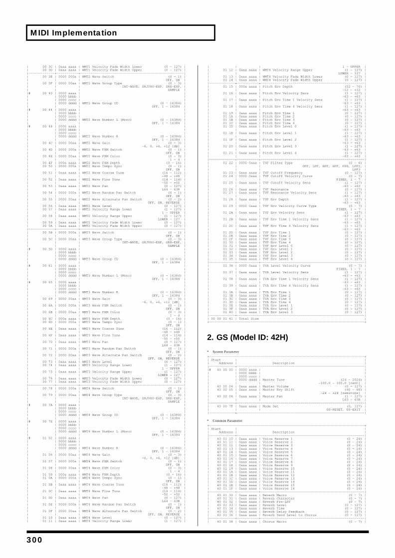
MIDI Implementation
| 00 3C | 0aaa aaaa | WMT1 Velocity Fade Width Lower (0 - 127) || 00 3D | 0aaa aaaa | WMT1 Velocity Fade Width Upper (0 - 127) ||—————————————+———————————+————————————————————————————————————————————————————|| 00 3E | 0000 000a | WMT2 Wave Switch (0 - 1) || | | OFF, ON || 00 3F | 0000 00aa | WMT2 Wave Group Type (0 - 3) || | | INT-WAVE, SRJV80-EXP, SRX-EXP, || | | SAMPLE ||# 00 40 | 0000 aaaa | || | 0000 bbbb | || | 0000 cccc | || | 0000 dddd | WMT2 Wave Group ID (0 - 16384) || | | OFF, 1 - 16384 ||# 00 44 | 0000 aaaa | || | 0000 bbbb | || | 0000 cccc | || | 0000 dddd | WMT2 Wave Number L (Mono) (0 - 16384) || | | OFF, 1 - 16384 ||# 00 48 | 0000 aaaa | || | 0000 bbbb | || | 0000 cccc | || | 0000 dddd | WMT2 Wave Number R (0 - 16384) || | | OFF, 1 - 16384 || 00 4C | 0000 00aa | WMT2 Wave Gain (0 - 3) || | | -6, 0, +6, +12 [dB] || 00 4D | 0000 000a | WMT2 Wave FXM Switch (0 - 1) || | | OFF, ON || 00 4E | 0000 00aa | WMT2 Wave FXM Color (0 - 3) || | | 1 - 4 || 00 4F | 000a aaaa | WMT2 Wave FXM Depth (0 - 16) || 00 50 | 0000 000a | WMT2 Wave Tempo Sync (0 - 1) || | | OFF, ON || 00 51 | 0aaa aaaa | WMT2 Wave Coarse Tune (16 - 112) || | | -48 - +48 || 00 52 | 0aaa aaaa | WMT2 Wave Fine Tune (14 - 114) || | | -50 - +50 || 00 53 | 0aaa aaaa | WMT2 Wave Pan (0 - 127) || | | L64 - 63R || 00 54 | 0000 000a | WMT2 Wave Random Pan Switch (0 - 1) || | | OFF, ON || 00 55 | 0000 00aa | WMT2 Wave Alternate Pan Switch (0 - 2) || | | OFF, ON, REVERSE || 00 56 | 0aaa aaaa | WMT2 Wave Level (0 - 127) || 00 57 | 0aaa aaaa | WMT2 Velocity Range Lower (1 - 127) || | | 1 - UPPER || 00 58 | 0aaa aaaa | WMT2 Velocity Range Upper (1 - 127) || | | LOWER - 127 || 00 59 | 0aaa aaaa | WMT2 Velocity Fade Width Lower (0 - 127) || 00 5A | 0aaa aaaa | WMT2 Velocity Fade Width Upper (0 - 127) ||—————————————+———————————+————————————————————————————————————————————————————|| 00 5B | 0000 000a | WMT3 Wave Switch (0 - 1) || | | OFF, ON || 00 5C | 0000 00aa | WMT3 Wave Group Type (0 - 3) || | | INT-WAVE, SRJV80-EXP, SRX-EXP, || | | SAMPLE ||# 00 5D | 0000 aaaa | || | 0000 bbbb | || | 0000 cccc | || | 0000 dddd | WMT3 Wave Group ID (0 - 16384) || | | OFF, 1 - 16384 ||# 00 61 | 0000 aaaa | || | 0000 bbbb | || | 0000 cccc | || | 0000 dddd | WMT3 Wave Number L (Mono) (0 - 16384) || | | OFF, 1 - 16384 ||# 00 65 | 0000 aaaa | || | 0000 bbbb | || | 0000 cccc | || | 0000 dddd | WMT3 Wave Number R (0 - 16384) || | | OFF, 1 - 16384 || 00 69 | 0000 00aa | WMT3 Wave Gain (0 - 3) || | | -6, 0, +6, +12 [dB] || 00 6A | 0000 000a | WMT3 Wave FXM Switch (0 - 1) || | | OFF, ON || 00 6B | 0000 00aa | WMT3 Wave FXM Color (0 - 3) || | | 1 - 4 || 00 6C | 000a aaaa | WMT3 Wave FXM Depth (0 - 16) || 00 6D | 0000 000a | WMT3 Wave Tempo Sync (0 - 1) || | | OFF, ON || 00 6E | 0aaa aaaa | WMT3 Wave Coarse Tune (16 - 112) || | | -48 - +48 || 00 6F | 0aaa aaaa | WMT3 Wave Fine Tune (14 - 114) || | | -50 - +50 || 00 70 | 0aaa aaaa | WMT3 Wave Pan (0 - 127) || | | L64 - 63R || 00 71 | 0000 000a | WMT3 Wave Random Pan Switch (0 - 1) || | | OFF, ON || 00 72 | 0000 00aa | WMT3 Wave Alternate Pan Switch (0 - 2) || | | OFF, ON, REVERSE || 00 73 | 0aaa aaaa | WMT3 Wave Level (0 - 127) || 00 74 | 0aaa aaaa | WMT3 Velocity Range Lower (1 - 127) || | | 1 - UPPER || 00 75 | 0aaa aaaa | WMT3 Velocity Range Upper (1 - 127) || | | LOWER - 127 || 00 76 | 0aaa aaaa | WMT3 Velocity Fade Width Lower (0 - 127) || 00 77 | 0aaa aaaa | WMT3 Velocity Fade Width Upper (0 - 127) ||—————————————+———————————+————————————————————————————————————————————————————|| 00 78 | 0000 000a | WMT4 Wave Switch (0 - 1) || | | OFF, ON || 00 79 | 0000 00aa | WMT4 Wave Group Type (0 - 3) || | | INT-WAVE, SRJV80-EXP, SRX-EXP, || | | SAMPLE ||# 00 7A | 0000 aaaa | || | 0000 bbbb | || | 0000 cccc | || | 0000 dddd | WMT4 Wave Group ID (0 - 16384) || | | OFF, 1 - 16384 ||# 00 7E | 0000 aaaa | || | 0000 bbbb | || | 0000 cccc | || | 0000 dddd | WMT4 Wave Number L (Mono) (0 - 16384) || | | OFF, 1 - 16384 ||# 01 02 | 0000 aaaa | || | 0000 bbbb | || | 0000 cccc | || | 0000 dddd | WMT4 Wave Number R (0 - 16384) || | | OFF, 1 - 16384 || 01 06 | 0000 00aa | WMT4 Wave Gain (0 - 3) || | | -6, 0, +6, +12 [dB] || 01 07 | 0000 000a | WMT4 Wave FXM Switch (0 - 1) || | | OFF, ON || 01 08 | 0000 00aa | WMT4 Wave FXM Color (0 - 3) || | | 1 - 4 || 01 09 | 000a aaaa | WMT4 Wave FXM Depth (0 - 16) || 01 0A | 0000 000a | WMT4 Wave Tempo Sync (0 - 1) || | | OFF, ON || 01 0B | 0aaa aaaa | WMT4 Wave Coarse Tune (16 - 112) || | | -48 - +48 || 01 0C | 0aaa aaaa | WMT4 Wave Fine Tune (14 - 114) || | | -50 - +50 || 01 0D | 0aaa aaaa | WMT4 Wave Pan (0 - 127) || | | L64 - 63R || 01 0E | 0000 000a | WMT4 Wave Random Pan Switch (0 - 1) || | | OFF, ON || 01 0F | 0000 00aa | WMT4 Wave Alternate Pan Switch (0 - 2) || | | OFF, ON, REVERSE || 01 10 | 0aaa aaaa | WMT4 Wave Level (0 - 127) || 01 11 | 0aaa aaaa | WMT4 Velocity Range Lower (1 - 127) |
| | | 1 - UPPER || 01 12 | 0aaa aaaa | WMT4 Velocity Range Upper (1 - 127) || | | LOWER - 127 || 01 13 | 0aaa aaaa | WMT4 Velocity Fade Width Lower (0 - 127) || 01 14 | 0aaa aaaa | WMT4 Velocity Fade Width Upper (0 - 127) ||—————————————+———————————+————————————————————————————————————————————————————|| 01 15 | 000a aaaa | Pitch Env Depth (52 - 76) || | | -12 - +12 || 01 16 | 0aaa aaaa | Pitch Env Velocity Sens (1 - 127) || | | -63 - +63 || 01 17 | 0aaa aaaa | Pitch Env Time 1 Velocity Sens (1 - 127) || | | -63 - +63 || 01 18 | 0aaa aaaa | Pitch Env Time 4 Velocity Sens (1 - 127) || | | -63 - +63 || 01 19 | 0aaa aaaa | Pitch Env Time 1 (0 - 127) || 01 1A | 0aaa aaaa | Pitch Env Time 2 (0 - 127) || 01 1B | 0aaa aaaa | Pitch Env Time 3 (0 - 127) || 01 1C | 0aaa aaaa | Pitch Env Time 4 (0 - 127) || 01 1D | 0aaa aaaa | Pitch Env Level 0 (1 - 127) || | | -63 - +63 || 01 1E | 0aaa aaaa | Pitch Env Level 1 (1 - 127) || | | -63 - +63 || 01 1F | 0aaa aaaa | Pitch Env Level 2 (1 - 127) || | | -63 - +63 || 01 20 | 0aaa aaaa | Pitch Env Level 3 (1 - 127) || | | -63 - +63 || 01 21 | 0aaa aaaa | Pitch Env Level 4 (1 - 127) || | | -63 - +63 ||—————————————+———————————+————————————————————————————————————————————————————|| 01 22 | 0000 0aaa | TVF Filter Type (0 - 6) || | | OFF, LPF, BPF, HPF, PKG, LPF2, || | | LPF3 || 01 23 | 0aaa aaaa | TVF Cutoff Frequency (0 - 127) || 01 24 | 0000 0aaa | TVF Cutoff Velocity Curve (0 - 7) || | | FIXED, 1 - 7 || 01 25 | 0aaa aaaa | TVF Cutoff Velocity Sens (1 - 127) || | | -63 - +63 || 01 26 | 0aaa aaaa | TVF Resonance (0 - 127) || 01 27 | 0aaa aaaa | TVF Resonance Velocity Sens (1 - 127) || | | -63 - +63 || 01 28 | 0aaa aaaa | TVF Env Depth (1 - 127) || | | -63 - +63 || 01 29 | 0000 0aaa | TVF Env Velocity Curve Type (0 - 7) || | | FIXED, 1 - 7 || 01 2A | 0aaa aaaa | TVF Env Velocity Sens (1 - 127) || | | -63 - +63 || 01 2B | 0aaa aaaa | TVF Env Time 1 Velocity Sens (1 - 127) || | | -63 - +63 || 01 2C | 0aaa aaaa | TVF Env Time 4 Velocity Sens (1 - 127) || | | -63 - +63 || 01 2D | 0aaa aaaa | TVF Env Time 1 (0 - 127) || 01 2E | 0aaa aaaa | TVF Env Time 2 (0 - 127) || 01 2F | 0aaa aaaa | TVF Env Time 3 (0 - 127) || 01 30 | 0aaa aaaa | TVF Env Time 4 (0 - 127) || 01 31 | 0aaa aaaa | TVF Env Level 0 (0 - 127) || 01 32 | 0aaa aaaa | TVF Env Level 1 (0 - 127) || 01 33 | 0aaa aaaa | TVF Env Level 2 (0 - 127) || 01 34 | 0aaa aaaa | TVF Env Level 3 (0 - 127) || 01 35 | 0aaa aaaa | TVF Env Level 4 (0 - 127) ||—————————————+———————————+————————————————————————————————————————————————————|| 01 36 | 0000 0aaa | TVA Level Velocity Curve (0 - 7) || | | FIXED, 1 - 7 || 01 37 | 0aaa aaaa | TVA Level Velocity Sens (1 - 127) || | | -63 - +63 || 01 38 | 0aaa aaaa | TVA Env Time 1 Velocity Sens (1 - 127) || | | -63 - +63 || 01 39 | 0aaa aaaa | TVA Env Time 4 Velocity Sens (1 - 127) || | | -63 - +63 || 01 3A | 0aaa aaaa | TVA Env Time 1 (0 - 127) || 01 3B | 0aaa aaaa | TVA Env Time 2 (0 - 127) || 01 3C | 0aaa aaaa | TVA Env Time 3 (0 - 127) || 01 3D | 0aaa aaaa | TVA Env Time 4 (0 - 127) || 01 3E | 0aaa aaaa | TVA Env Level 1 (0 - 127) || 01 3F | 0aaa aaaa | TVA Env Level 2 (0 - 127) || 01 40 | 0aaa aaaa | TVA Env Level 3 (0 - 127) ||—————————————+————————————————————————————————————————————————————————————————|| 00 00 01 41 | Total Size |+——————————————————————————————————————————————————————————————————————————————+
2. GS (Model ID: 42H)
* System Parameter+——————————————————————————————————————————————————————————————————————————————+| Start | || Address | Description ||—————————————+————————————————————————————————————————————————————————————————||# 40 00 00 | 0000 aaaa | || | 0000 bbbb | || | 0000 cccc | || | 0000 dddd | Master Tune (24 - 2024) || | | -100.0 - 100.0 [cent] || 40 00 04 | 0aaa aaaa | Master Volume (0 - 127) || 40 00 05 | 0aaa aaaa | Master Key Shift (40 - 88) || | | -24 - +24 [semitone] || 40 00 06 | 0aaa aaaa | Master Pan (1 - 127) || | | L63 - 63R ||—————————————+————————————————————————————————————————————————————————————————|| 40 00 7F | 0aaa aaaa | Mode Set (0, 127) || | | GS-RESET, GS-EXIT ||—————————————+————————————————————————————————————————————————————————————————|
* Common Parameter+——————————————————————————————————————————————————————————————————————————————+| Start | || Address | Description ||—————————————+————————————————————————————————————————————————————————————————|| 40 01 10 | 0aaa aaaa | Voice Reserve 1 (0 - 24) || 40 01 11 | 0aaa aaaa | Voice Reserve 2 (0 - 24) || 40 01 12 | 0aaa aaaa | Voice Reserve 3 (0 - 24) || 40 01 13 | 0aaa aaaa | Voice Reserve 4 (0 - 24) || 40 01 14 | 0aaa aaaa | Voice Reserve 5 (0 - 24) || 40 01 15 | 0aaa aaaa | Voice Reserve 6 (0 - 24) || 40 01 16 | 0aaa aaaa | Voice Reserve 7 (0 - 24) || 40 01 17 | 0aaa aaaa | Voice Reserve 8 (0 - 24) || 40 01 18 | 0aaa aaaa | Voice Reserve 9 (0 - 24) || 40 01 19 | 0aaa aaaa | Voice Reserve 10 (0 - 24) || 40 01 1A | 0aaa aaaa | Voice Reserve 11 (0 - 24) || 40 01 1B | 0aaa aaaa | Voice Reserve 12 (0 - 24) || 40 01 1C | 0aaa aaaa | Voice Reserve 13 (0 - 24) || 40 01 1D | 0aaa aaaa | Voice Reserve 14 (0 - 24) || 40 01 1E | 0aaa aaaa | Voice Reserve 15 (0 - 24) || 40 01 1F | 0aaa aaaa | Voice Reserve 16 (0 - 24) ||—————————————+———————————+————————————————————————————————————————————————————|| 40 01 30 | 0aaa aaaa | Reverb Macro (0 - 7) || 40 01 31 | 0aaa aaaa | Reverb Character (0 - 7) || 40 01 32 | 0aaa aaaa | Reverb Pre-LPF (0 - 7) || 40 01 33 | 0aaa aaaa | Reverb Level (0 - 127) || 40 01 34 | 0aaa aaaa | Reverb Time (0 - 127) || 40 01 35 | 0aaa aaaa | Reverb Delay Feedback (0 - 127) || 40 01 36 | 0aaa aaaa | Reverb Send Level to Chorus (0 - 127) ||—————————————+———————————+————————————————————————————————————————————————————|| 40 01 38 | 0aaa aaaa | Chorus Macro (0 - 7) |
300
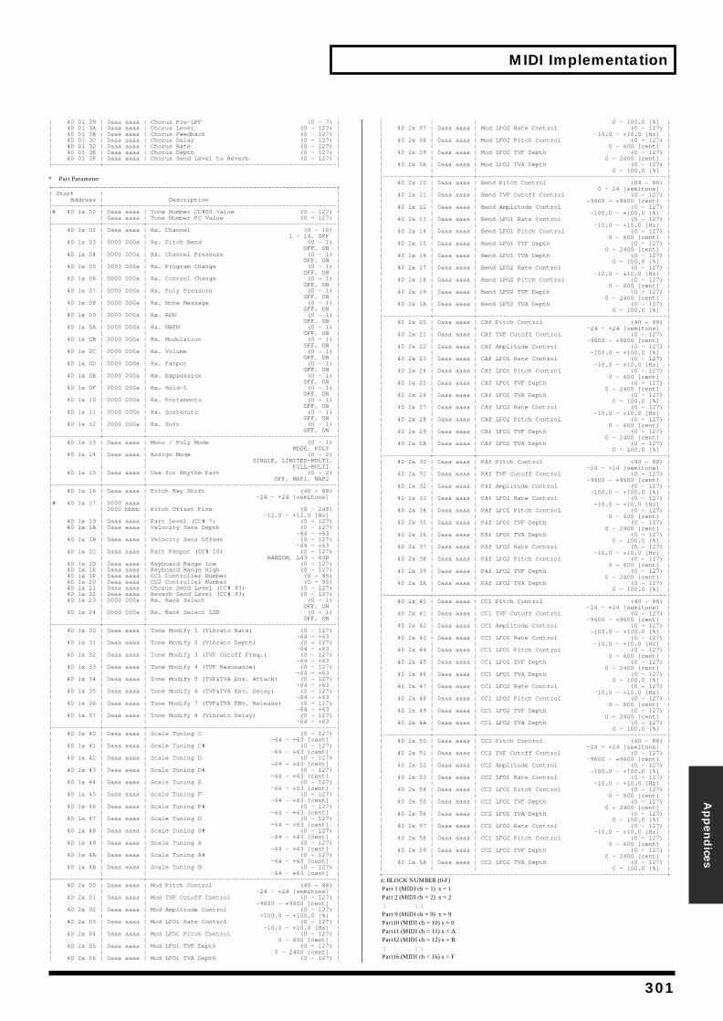
MIDI Implementation
Appen
dices
| 40 01 39 | 0aaa aaaa | Chorus Pre-LPF (0 - 7) || 40 01 3A | 0aaa aaaa | Chorus Level (0 - 127) || 40 01 3B | 0aaa aaaa | Chorus Feedback (0 - 127) || 40 01 3C | 0aaa aaaa | Chorus Delay (0 - 127) || 40 01 3D | 0aaa aaaa | Chorus Rate (0 - 127) || 40 01 3E | 0aaa aaaa | Chorus Depth (0 - 127) || 40 01 3F | 0aaa aaaa | Chorus Send Level to Reverb (0 - 127) ||—————————————+————————————————————————————————————————————————————————————————|
* Part Parameter+——————————————————————————————————————————————————————————————————————————————+| Start | || Address | Description ||—————————————+————————————————————————————————————————————————————————————————||# 40 1x 00 | 0aaa aaaa | Tone Number CC#00 Value (0 - 127) || | 0aaa aaaa | Tone Number PC Value (0 - 127) ||—————————————+———————————+————————————————————————————————————————————————————|| 40 1x 02 | 0aaa aaaa | Rx. Channel (0 - 16) || | | 1 - 16, OFF || 40 1x 03 | 0000 000a | Rx. Pitch Bend (0 - 1) || | | OFF, ON || 40 1x 04 | 0000 000a | Rx. Channel Pressure (0 - 1) || | | OFF, ON || 40 1x 05 | 0000 000a | Rx. Program Change (0 - 1) || | | OFF, ON || 40 1x 06 | 0000 000a | Rx. Control Change (0 - 1) || | | OFF, ON || 40 1x 07 | 0000 000a | Rx. Poly Pressure (0 - 1) || | | OFF, ON || 40 1x 08 | 0000 000a | Rx. Note Message (0 - 1) || | | OFF, ON || 40 1x 09 | 0000 000a | Rx. RPN (0 - 1) || | | OFF, ON || 40 1x 0A | 0000 000a | Rx. NRPN (0 - 1) || | | OFF, ON || 40 1x 0B | 0000 000a | Rx. Modulation (0 - 1) || | | OFF, ON || 40 1x 0C | 0000 000a | Rx. Volume (0 - 1) || | | OFF, ON || 40 1x 0D | 0000 000a | Rx. Panpot (0 - 1) || | | OFF, ON || 40 1x 0E | 0000 000a | Rx. Expression (0 - 1) || | | OFF, ON || 40 1x 0F | 0000 000a | Rx. Hold-1 (0 - 1) || | | OFF, ON || 40 1x 10 | 0000 000a | Rx. Portamento (0 - 1) || | | OFF, ON || 40 1x 11 | 0000 000a | Rx. Sostenuto (0 - 1) || | | OFF, ON || 40 1x 12 | 0000 000a | Rx. Soft (0 - 1) || | | OFF, ON ||—————————————+———————————+————————————————————————————————————————————————————|| 40 1x 13 | 0aaa aaaa | Mono / Poly Mode (0 - 1) || | | MODE, POLY || 40 1x 14 | 0aaa aaaa | Assign Mode (0 - 2) || | | SINGLE, LIMITED-MULTI, || | | FULL-MULTI || 40 1x 15 | 0aaa aaaa | Use for Rhythm Part (0 - 2) || | | OFF, MAP1, MAP2 ||—————————————+———————————+————————————————————————————————————————————————————|| 40 1x 16 | 0aaa aaaa | Pitch Key Shift (40 - 88) || | | -24 - +24 [semitone] ||# 40 1x 17 | 0000 aaaa | || | 0000 bbbb | Pitch Offset Fine (8 - 248) || | | -12.0 - +12.0 [Hz] || 40 1x 19 | 0aaa aaaa | Part Level (CC# 7) (0 - 127) || 40 1x 1A | 0aaa aaaa | Velocity Sens Depth (0 - 127) || | | -64 - +63 || 40 1x 1B | 0aaa aaaa | Velocity Sens Offset (0 - 127) || | | -64 - +63 || 40 1x 1C | 0aaa aaaa | Part Panpot (CC# 10) (0 - 127) || | | RANDOM, L63 - 63R || 40 1x 1D | 0aaa aaaa | Keyboard Range Low (0 - 127) || 40 1x 1E | 0aaa aaaa | Keyboard Range High (0 - 127) || 40 1x 1F | 0aaa aaaa | CC1 Controller Number (0 - 95) || 40 1x 20 | 0aaa aaaa | CC2 Controller Number (0 - 95) || 40 1x 21 | 0aaa aaaa | Chorus Send Level (CC# 93) (0 - 127) || 40 1x 22 | 0aaa aaaa | Reverb Send Level (CC# 93) (0 - 127) || 40 1x 23 | 0000 000a | Rx. Bank Select (0 - 1) || | | OFF, ON || 40 1x 24 | 0000 000a | Rx. Bank Select LSB (0 - 1) || | | OFF, ON ||—————————————+———————————+————————————————————————————————————————————————————|| 40 1x 30 | 0aaa aaaa | Tone Modify 1 (Vibrato Rate) (0 - 127) || | | -64 - +63 || 40 1x 31 | 0aaa aaaa | Tone Modify 2 (Vibrato Depth) (0 - 127) || | | -64 - +63 || 40 1x 32 | 0aaa aaaa | Tone Modify 3 (TVF Cutoff Freq.) (0 - 127) || | | -64 - +63 || 40 1x 33 | 0aaa aaaa | Tone Modify 4 (TVF Resonance) (0 - 127) || | | -64 - +63 || 40 1x 34 | 0aaa aaaa | Tone Modify 5 (TVF&TVA Env. Attack) (0 - 127) || | | -64 - +63 || 40 1x 35 | 0aaa aaaa | Tone Modify 6 (TVF&TVA Env. Decay) (0 - 127) || | | -64 - +63 || 40 1x 36 | 0aaa aaaa | Tone Modify 7 (TVF&TVA ENv. Release) (0 - 127) || | | -64 - +63 || 40 1x 37 | 0aaa aaaa | Tone Modify 8 (Vibrato Delay) (0 - 127) || | | -64 - +63 ||—————————————+———————————+————————————————————————————————————————————————————|| 40 1x 40 | 0aaa aaaa | Scale Tuning C (0 - 127) || | | -64 - +63 [cent] || 40 1x 41 | 0aaa aaaa | Scale Tuning C# (0 - 127) || | | -64 - +63 [cent] || 40 1x 42 | 0aaa aaaa | Scale Tuning D (0 - 127) || | | -64 - +63 [cent] || 40 1x 43 | 0aaa aaaa | Scale Tuning D# (0 - 127) || | | -64 - +63 [cent] || 40 1x 44 | 0aaa aaaa | Scale Tuning E (0 - 127) || | | -64 - +63 [cent] || 40 1x 45 | 0aaa aaaa | Scale Tuning F (0 - 127) || | | -64 - +63 [cent] || 40 1x 46 | 0aaa aaaa | Scale Tuning F# (0 - 127) || | | -64 - +63 [cent] || 40 1x 47 | 0aaa aaaa | Scale Tuning G (0 - 127) || | | -64 - +63 [cent] || 40 1x 48 | 0aaa aaaa | Scale Tuning G# (0 - 127) || | | -64 - +63 [cent] || 40 1x 49 | 0aaa aaaa | Scale Tuning A (0 - 127) || | | -64 - +63 [cent] || 40 1x 4A | 0aaa aaaa | Scale Tuning A# (0 - 127) || | | -64 - +63 [cent] || 40 1x 4B | 0aaa aaaa | Scale Tuning B (0 - 127) || | | -64 - +63 [cent] ||—————————————+———————————+————————————————————————————————————————————————————|| 40 2x 00 | 0aaa aaaa | Mod Pitch Control (40 - 88) || | | -24 - +24 [semitone] || 40 2x 01 | 0aaa aaaa | Mod TVF Cutoff Control (0 - 127) || | | -9600 - +9600 [cent] || 40 2x 02 | 0aaa aaaa | Mod Amplitude Control (0 - 127) || | | -100.0 - +100.0 [%] || 40 2x 03 | 0aaa aaaa | Mod LFO1 Rate Control (0 - 127) || | | -10.0 - +10.0 [Hz] || 40 2x 04 | 0aaa aaaa | Mod LFO1 Pitch Control (0 - 127) || | | 0 - 600 [cent] || 40 2x 05 | 0aaa aaaa | Mod LFO1 TVF Depth (0 - 127) || | | 0 - 2400 [cent] || 40 2x 06 | 0aaa aaaa | Mod LFO1 TVA Depth (0 - 127) |
| | | 0 - 100.0 [%] || 40 2x 07 | 0aaa aaaa | Mod LFO2 Rate Control (0 - 127) || | | -10.0 - +10.0 [Hz] || 40 2x 08 | 0aaa aaaa | Mod LFO2 Pitch Control (0 - 127) || | | 0 - 600 [cent] || 40 2x 09 | 0aaa aaaa | Mod LFO2 TVF Depth (0 - 127) || | | 0 - 2400 [cent] || 40 2x 0A | 0aaa aaaa | Mod LFO2 TVA Depth (0 - 127) || | | 0 - 100.0 [%] ||—————————————+———————————+————————————————————————————————————————————————————|| 40 2x 10 | 0aaa aaaa | Bend Pitch Control (64 - 88) || | | 0 - 24 [semitone] || 40 2x 11 | 0aaa aaaa | Bend TVF Cutoff Control (0 - 127) || | | -9600 - +9600 [cent] || 40 2x 12 | 0aaa aaaa | Bend Amplitude Control (0 - 127) || | | -100.0 - +100.0 [%] || 40 2x 13 | 0aaa aaaa | Bend LFO1 Rate Control (0 - 127) || | | -10.0 - +10.0 [Hz] || 40 2x 14 | 0aaa aaaa | Bend LFO1 Pitch Control (0 - 127) || | | 0 - 600 [cent] || 40 2x 15 | 0aaa aaaa | Bend LFO1 TVF Depth (0 - 127) || | | 0 - 2400 [cent] || 40 2x 16 | 0aaa aaaa | Bend LFO1 TVA Depth (0 - 127) || | | 0 - 100.0 [%] || 40 2x 17 | 0aaa aaaa | Bend LFO2 Rate Control (0 - 127) || | | -10.0 - +10.0 [Hz] || 40 2x 18 | 0aaa aaaa | Bend LFO2 Pitch Control (0 - 127) || | | 0 - 600 [cent] || 40 2x 19 | 0aaa aaaa | Bend LFO2 TVF Depth (0 - 127) || | | 0 - 2400 [cent] || 40 2x 1A | 0aaa aaaa | Bend LFO2 TVA Depth (0 - 127) || | | 0 - 100.0 [%] ||—————————————+———————————+————————————————————————————————————————————————————|| 40 2x 20 | 0aaa aaaa | CAf Pitch Control (40 - 88) || | | -24 - +24 [semitone] || 40 2x 21 | 0aaa aaaa | CAf TVF Cutoff Control (0 - 127) || | | -9600 - +9600 [cent] || 40 2x 22 | 0aaa aaaa | CAf Amplitude Control (0 - 127) || | | -100.0 - +100.0 [%] || 40 2x 23 | 0aaa aaaa | CAf LFO1 Rate Control (0 - 127) || | | -10.0 - +10.0 [Hz] || 40 2x 24 | 0aaa aaaa | CAf LFO1 Pitch Control (0 - 127) || | | 0 - 600 [cent] || 40 2x 25 | 0aaa aaaa | CAf LFO1 TVF Depth (0 - 127) || | | 0 - 2400 [cent] || 40 2x 26 | 0aaa aaaa | CAf LFO1 TVA Depth (0 - 127) || | | 0 - 100.0 [%] || 40 2x 27 | 0aaa aaaa | CAf LFO2 Rate Control (0 - 127) || | | -10.0 - +10.0 [Hz] || 40 2x 28 | 0aaa aaaa | CAf LFO2 Pitch Control (0 - 127) || | | 0 - 600 [cent] || 40 2x 29 | 0aaa aaaa | CAf LFO2 TVF Depth (0 - 127) || | | 0 - 2400 [cent] || 40 2x 2A | 0aaa aaaa | CAf LFO2 TVA Depth (0 - 127) || | | 0 - 100.0 [%] ||—————————————+———————————+————————————————————————————————————————————————————|| 40 2x 30 | 0aaa aaaa | PAf Pitch Control (40 - 88) || | | -24 - +24 [semitone] || 40 2x 31 | 0aaa aaaa | PAf TVF Cutoff Control (0 - 127) || | | -9600 - +9600 [cent] || 40 2x 32 | 0aaa aaaa | PAf Amplitude Control (0 - 127) || | | -100.0 - +100.0 [%] || 40 2x 33 | 0aaa aaaa | PAf LFO1 Rate Control (0 - 127) || | | -10.0 - +10.0 [Hz] || 40 2x 34 | 0aaa aaaa | PAf LFO1 Pitch Control (0 - 127) || | | 0 - 600 [cent] || 40 2x 35 | 0aaa aaaa | PAf LFO1 TVF Depth (0 - 127) || | | 0 - 2400 [cent] || 40 2x 36 | 0aaa aaaa | PAf LFO1 TVA Depth (0 - 127) || | | 0 - 100.0 [%] || 40 2x 37 | 0aaa aaaa | PAf LFO2 Rate Control (0 - 127) || | | -10.0 - +10.0 [Hz] || 40 2x 38 | 0aaa aaaa | PAf LFO2 Pitch Control (0 - 127) || | | 0 - 600 [cent] || 40 2x 39 | 0aaa aaaa | PAf LFO2 TVF Depth (0 - 127) || | | 0 - 2400 [cent] || 40 2x 3A | 0aaa aaaa | PAf LFO2 TVA Depth (0 - 127) || | | 0 - 100.0 [%] ||—————————————+———————————+————————————————————————————————————————————————————|| 40 2x 40 | 0aaa aaaa | CC1 Pitch Control (40 - 88) || | | -24 - +24 [semitone] || 40 2x 41 | 0aaa aaaa | CC1 TVF Cutoff Control (0 - 127) || | | -9600 - +9600 [cent] || 40 2x 42 | 0aaa aaaa | CC1 Amplitude Control (0 - 127) || | | -100.0 - +100.0 [%] || 40 2x 43 | 0aaa aaaa | CC1 LFO1 Rate Control (0 - 127) || | | -10.0 - +10.0 [Hz] || 40 2x 44 | 0aaa aaaa | CC1 LFO1 Pitch Control (0 - 127) || | | 0 - 600 [cent] || 40 2x 45 | 0aaa aaaa | CC1 LFO1 TVF Depth (0 - 127) || | | 0 - 2400 [cent] || 40 2x 46 | 0aaa aaaa | CC1 LFO1 TVA Depth (0 - 127) || | | 0 - 100.0 [%] || 40 2x 47 | 0aaa aaaa | CC1 LFO2 Rate Control (0 - 127) || | | -10.0 - +10.0 [Hz] || 40 2x 48 | 0aaa aaaa | CC1 LFO2 Pitch Control (0 - 127) || | | 0 - 600 [cent] || 40 2x 49 | 0aaa aaaa | CC1 LFO2 TVF Depth (0 - 127) || | | 0 - 2400 [cent] || 40 2x 4A | 0aaa aaaa | CC1 LFO2 TVA Depth (0 - 127) || | | 0 - 100.0 [%] ||—————————————+———————————+————————————————————————————————————————————————————|| 40 2x 50 | 0aaa aaaa | CC2 Pitch Control (40 - 88) || | | -24 - +24 [semitone] || 40 2x 51 | 0aaa aaaa | CC2 TVF Cutoff Control (0 - 127) || | | -9600 - +9600 [cent] || 40 2x 52 | 0aaa aaaa | CC2 Amplitude Control (0 - 127) || | | -100.0 - +100.0 [%] || 40 2x 53 | 0aaa aaaa | CC2 LFO1 Rate Control (0 - 127) || | | -10.0 - +10.0 [Hz] || 40 2x 54 | 0aaa aaaa | CC2 LFO1 Pitch Control (0 - 127) || | | 0 - 600 [cent] || 40 2x 55 | 0aaa aaaa | CC2 LFO1 TVF Depth (0 - 127) || | | 0 - 2400 [cent] || 40 2x 56 | 0aaa aaaa | CC2 LFO1 TVA Depth (0 - 127) || | | 0 - 100.0 [%] || 40 2x 57 | 0aaa aaaa | CC2 LFO2 Rate Control (0 - 127) || | | -10.0 - +10.0 [Hz] || 40 2x 58 | 0aaa aaaa | CC2 LFO2 Pitch Control (0 - 127) || | | 0 - 600 [cent] || 40 2x 59 | 0aaa aaaa | CC2 LFO2 TVF Depth (0 - 127) || | | 0 - 2400 [cent] || 40 2x 5A | 0aaa aaaa | CC2 LFO2 TVA Depth (0 - 127) || | | 0 - 100.0 [%] |+——————————————————————————————————————————————————————————————————————————————+ x: BLOCK NUMBER (0-F) Part 1 (MIDI ch = 1) x = 1 Part 2 (MIDI ch = 2) x = 2 : : : Part 9 (MIDI ch = 9) x = 9 Part10 (MIDI ch = 10) x = 0 Part11 (MIDI ch = 11) x = A Part12 (MIDI ch = 12) x = B : : : Part16 (MIDI ch = 16) x = F
301

MIDI Implementation
* Drum Setup Parameter+——————————————————————————————————————————————————————————————————————————————+| Start | || Address | Description ||—————————————+————————————————————————————————————————————————————————————————|| 41 m0 00 | 0aaa aaaa | Drum Map Name 1 (32 - 127) || | | 32 - 127 [ASCII] || 41 m0 01 | 0aaa aaaa | Drum Map Name 2 (32 - 127) || | | 32 - 127 [ASCII] || 41 m0 02 | 0aaa aaaa | Drum Map Name 3 (32 - 127) || | | 32 - 127 [ASCII] || 41 m0 03 | 0aaa aaaa | Drum Map Name 4 (32 - 127) || | | 32 - 127 [ASCII] || 41 m0 04 | 0aaa aaaa | Drum Map Name 5 (32 - 127) || | | 32 - 127 [ASCII] || 41 m0 05 | 0aaa aaaa | Drum Map Name 6 (32 - 127) || | | 32 - 127 [ASCII] || 41 m0 06 | 0aaa aaaa | Drum Map Name 7 (32 - 127) || | | 32 - 127 [ASCII] || 41 m0 07 | 0aaa aaaa | Drum Map Name 8 (32 - 127) || | | 32 - 127 [ASCII] || 41 m0 08 | 0aaa aaaa | Drum Map Name 9 (32 - 127) || | | 32 - 127 [ASCII] || 41 m0 09 | 0aaa aaaa | Drum Map Name 10 (32 - 127) || | | 32 - 127 [ASCII] || 41 m0 0A | 0aaa aaaa | Drum Map Name 11 (32 - 127) || | | 32 - 127 [ASCII] || 41 m0 0B | 0aaa aaaa | Drum Map Name 12 (32 - 127) || | | 32 - 127 [ASCII] ||—————————————+———————————+————————————————————————————————————————————————————|| 41 m1 rr | 0aaa aaaa | Play Note Number (0 - 127) || 41 m2 rr | 0aaa aaaa | Level (0 - 127) || 41 m3 rr | 0aaa aaaa | Assign Group Number (0 - 127) || | | NON, 1 - 127 || 41 m4 rr | 0aaa aaaa | Panpot (0 - 127) || | | RAMDOM, L63 - 63R || 41 m5 rr | 0aaa aaaa | Reverb Send Level (0 - 127) || | | 0.0 - 1.0 || 41 m6 rr | 0aaa aaaa | Chorus Send Level (0 - 127) || | | 0.0 - 1.0 || 41 m7 rr | 0000 000a | Rx. Note Off (0 - 1) || | | OFF, ON || 41 m8 rr | 0000 000a | Rx. Note On (0 - 1) || | | OFF, ON ||—————————————+————————————————————————————————————————————————————————————————| m: Map number (0 = MAP1, 1 = MAP2) rr: drum part note number (00H-7FH)
● Decimal and Hexadecimal table (An "H" is appended to the end of numbers in hexadecimal notation.)
In MIDI documentation, data values and addresses/sizes of Exclusive messages, etc. areexpressed as hexadecimal values for each 7 bits.The following table shows how these correspond to decimal numbers.
+——————+——————++——————+——————++——————+——————++——————+——————+| D | H || D | H || D | H || D | H |+——————+——————++——————+——————++——————+——————++——————+——————+| 0 | 00H || 32 | 20H || 64 | 40H || 96 | 60H || 1 | 01H || 33 | 21H || 65 | 41H || 97 | 61H || 2 | 02H || 34 | 22H || 66 | 42H || 98 | 62H || 3 | 03H || 35 | 23H || 67 | 43H || 99 | 63H || 4 | 04H || 36 | 24H || 68 | 44H || 100 | 64H || 5 | 05H || 37 | 25H || 69 | 45H || 101 | 65H || 6 | 06H || 38 | 26H || 70 | 46H || 102 | 66H || 7 | 07H || 39 | 27H || 71 | 47H || 103 | 67H || 8 | 08H || 40 | 28H || 72 | 48H || 104 | 68H || 9 | 09H || 41 | 29H || 73 | 49H || 105 | 69H || 10 | 0AH || 42 | 2AH || 74 | 4AH || 106 | 6AH || 11 | 0BH || 43 | 2BH || 75 | 4BH || 107 | 6BH || 12 | 0CH || 44 | 2CH || 76 | 4CH || 108 | 6CH || 13 | 0DH || 45 | 2DH || 77 | 4DH || 109 | 6DH || 14 | 0EH || 46 | 2EH || 78 | 4EH || 110 | 6EH || 15 | 0FH || 47 | 2FH || 79 | 4FH || 111 | 6FH || 16 | 10H || 48 | 30H || 80 | 50H || 112 | 70H || 17 | 11H || 49 | 31H || 81 | 51H || 113 | 71H || 18 | 12H || 50 | 32H || 82 | 52H || 114 | 72H || 19 | 13H || 51 | 33H || 83 | 53H || 115 | 73H || 20 | 14H || 52 | 34H || 84 | 54H || 116 | 74H || 21 | 15H || 53 | 35H || 85 | 55H || 117 | 75H || 22 | 16H || 54 | 36H || 86 | 56H || 118 | 76H || 23 | 17H || 55 | 37H || 87 | 57H || 119 | 77H || 24 | 18H || 56 | 38H || 88 | 58H || 120 | 78H || 25 | 19H || 57 | 39H || 89 | 59H || 121 | 79H || 26 | 1AH || 58 | 3AH || 90 | 5AH || 122 | 7AH || 27 | 1BH || 59 | 3BH || 91 | 5BH || 123 | 7BH || 28 | 1CH || 60 | 3CH || 92 | 5CH || 124 | 7CH || 29 | 1DH || 61 | 3DH || 93 | 5DH || 125 | 7DH || 30 | 1EH || 62 | 3EH || 94 | 5EH || 126 | 7EH || 31 | 1FH || 63 | 3FH || 95 | 5FH || 127 | 7FH |+——————+——————++——————+——————++——————+——————++——————+——————+D:decimalH:hexadecimal
* Decimal values such as MIDI channel, bank select, and program change are listed as onegreater than the values given in the above table.
* A 7-bit byte can express data in the range of 128 steps. For data where greater precisionis required, we must use two or more bytes. For example, two hexadecimal numbers aabbH expressing two 7-bit bytes would indicate a value of aa x 128+bb.
* In the case of values which have a +/- sign, 00H = -64, 40H = +/-0, and 7FH = +63, sothat the decimal expression would be 64 less than the value given in the above chart. Inthe case of two types, 00 00H = -8192, 40 00H = +/-0, and 7F 7FH = +8191. For example, ifaa bbH were expressed as decimal, this would be aa bbH - 40 00H = aa x 128+bb - 64 x128.
* Data marked "Use nibbled data" is expressed in hexadecimal in 4-bit units. A valueexpressed as a 2-byte nibble 0a 0bH has the value of a x 16+b.
<Example 1> What is the decimal expression of 5AH ?From the preceding table, 5AH = 90
<Example 2> What is the decimal expression of the value 12 34H given as hexadecimal foreach 7 bits?From the preceding table, since 12H = 18 and 34H = 5218 x 128+52 = 2356
<Example 3> What is the decimal expression of the nibbled value 0A 03 09 0D ?From the preceding table, since 0AH = 10, 03H = 3, 09H = 9, 0DH = 13((10 x 16+3) x 16+9) x 16+13 = 41885
<Example 4> What is the nibbled expression of the decimal value 1258?
16) 125816) 78 ... 1016) 4 ... 14 0 ... 4
Since from the preceding table, 0 = 00H, 4 = 04H, 14 = 0EH, 10 = 0AH, the result is: 00 04 0E0AH.
● Examples of actual MIDI messages
<Example 1> 92 3E 5F9n is the Note-on status, and n is the MIDI channel number. Since 2H = 2, 3EH = 62, and5FH = 95, this is a Note-on message with MIDI CH = 3, note number 62 (note name is D4),and velocity 95.
<Example 2> CE 49CnH is the Program Change status, and n is the MIDI channel number. Since EH = 14 and49H = 73, this is a Program Change message with MIDI CH = 15, program number 74 (Flutein GS).
<Example 3> EA 00 28EnH is the Pitch Bend Change status, and n is the MIDI channel number. The 2nd byte (00H= 0) is the LSB and the 3rd byte (28H = 40) is the MSB, but Pitch Bend Value is a signednumber in which 40 00H (= 64 x 12+80 = 8192) is 0, so this Pitch Bend Value is28 00H - 40 00H = 40 x 12+80 - (64 x 12+80) = 5120 - 8192 = -3072
If the Pitch Bend Sensitivity is set to 2 semitones, -8192 (00 00H) will cause the pitch tochange -200 cents, so in this case -200 x (-3072) ÷ (-8192) = -75 cents of Pitch Bend is beingapplied to MIDI channel 11.
<Example 4> B3 64 00 65 00 06 0C 26 00 64 7F 65 7FBnH is the Control Change status, and n is the MIDI channel number. For Control Changes,the 2nd byte is the control number, and the 3rd byte is the value. In a case in which two ormore messages consecutive messages have the same status, MIDI has a provision called"running status" which allows the status byte of the second and following messages to beomitted. Thus, the above messages have the following meaning.
B3 64 00 MIDI ch.4, lower byte of RPN parameternumber: 00H(B3) 65 00 (MIDI ch.4) upper byte of RPN parameternumber: 00H(B3) 06 0C (MIDI ch.4) upper byte of parameter value:0CH(B3) 26 00 (MIDI ch.4) lower byte of parameter value:00H(B3) 64 7F (MIDI ch.4) lower byte of RPN parameternumber: 7FH(B3) 65 7F (MIDI ch.4) upper byte of RPN parameternumber: 7FH
In other words, the above messages specify a value of 0C 00H for RPN parameter number00 00H on MIDI channel 4, and then set the RPN parameter number to 7F 7FH.
RPN parameter number 00 00H is Pitch Bend Sensitivity, and the MSB of the value indicatessemitone units, so a value of 0CH = 12 sets the maximum pitch bend range to +/-12semitones (1 octave). (On GS sound generators the LSB of Pitch Bend Sensitivity is ignored,but the LSB should be transmitted anyway (with a value of 0) so that operation will becorrect on any device.)
Once the parameter number has been specified for RPN or NRPN, all Data Entry messagestransmitted on that same channel will be valid, so after the desired value has beentransmitted, it is a good idea to set the parameter number to 7F 7FH to prevent accidents.This is the reason for the (B3) 64 7F (B3) 65 7F at the end.
It is not desirable for performance data (such as Standard MIDI File data) to contain manyevents with running status as given in <Example 4>. This is because if playback is halted
302
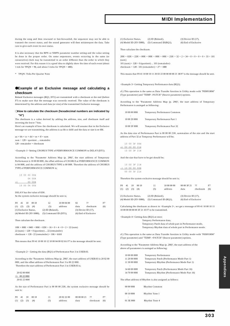
MIDI Implementation
during the song and then rewound or fastransmit the correct status, and the sound care to give each event its own status.
It is also necessary that the RPN or NRPN be done in the proper order. On some consecutive) clock may be transmitted in awere received. For this reason it is a good id1 tick for TPQN = 96, and about 5 ticks for T
* TPQN: Ticks Per Quarter Note
●
Example of an Exclusivechecksum
Roland Exclusive messages (RQ1, DT1) areF7) to make sure that the message was codetermined by the address and data (or size
❍
How to calculate the checksum (h
"H")
The checksum is a value derived by addiinverting the lower 7 bits.Here's an example of how the checksum is message we are transmitting, the address is
aa + bb + cc + dd + ee + ff = sumsum ÷ 128 = quotient ... remainder 128 - remainder = checksum
<Example 1> Setting CHORUS TYPE of PER
According to the "Parameter Address MPerformance is 10 00 00 00H, the offset addris 04 00H, and the address of CHORUS TYPTYPE of PERFORMANCE COMMON is;
10 00 00 00H
04 00H
+) 00 00H
10 00 04 00H
DELAY has the value of 02H. So the system exclusive message should be
F0 41 10 00 10 12 1(1) (2) (3) (4) (5) a(1) Exclusive Status, (2) ID (Roland),(4) Model ID (XV-5080), (5) Command ID
Then calculate the checksum.
10H + 00H + 04H + 00H + 02H = 16 + 0 + 4 +22 (sum) ÷ 128 = 0 (quotient) ... 22 (remaindchecksum = 128 - 22 (remainder) = 106 = 6A
This means that F0 41 10 00 10 12 10 00 04 00
<Example 2> Getting the data (RQ1) of Per
According to the "Parameter Address Map 00H, and the offset address of Performance Therefore the start address of Performance
20 02 00 00H+) 00 22 00H 20 02 22 00H
As the size of Performance Part is 00 00 00sent is;
F0 41 10 00 10 11 2(1) (2) (3) (4) (5) a
Appen
dices
t-forwarded, the sequencer may not be able togenerator will then misinterpret the data. Take
parameter number setting and the value settingsequencers, events occurring in the same (orn order different than the order in which theyea to slightly skew the time of each event (aboutPQN = 480).
message and calculating a
transmitted with a checksum at the end (beforerrectly received. The value of the checksum is) of the transmitted Exclusive message.
exadecimal numbers are indicated by
ng the address, size, and checksum itself and
calculated. We will assume that in the Exclusive aa bb cc ddH and the data or size is ee ffH.
FORMANCE COMMON to DELAY (DT1).
ap (p. 290)", the start address of Temporaryess of CHORUS at PERFORMANCE COMMONE is 00 00H. Therefore the address of CHORUS
sent is;
0 00 04 00 02 ?? F7ddress data checksum (6)
(3) Device ID (17), (DT1), (6) End of Exclusive
0 + 2 = 22 (sum)er) H
02 6A F7 is the message should be sent.
formance Part 3 in USER:03.
(p. 290)", the start address of USER:03 is 20 02 00Part 3 is 00 22 00H.Part 3 in USER:03 is;
21H, the system exclusive message should be
0 02 22 00 00 00 00 21 ?? F7ddress data checksum (6)
(1) Exclusive Status, (2) ID (Roland), (3) Device ID (17),(4) Model ID (XV-5080), (5) Command ID(RQ1), (6) End of Exclusive
Then calculate the checksum.
20H + 02H + 22H + 00H + 00H + 00H + 00H + 21H = 32 + 2 + 34 + 0 + 0 + 0 + 0 + 33 = 101(sum)101 (sum) ÷ 128 = 0 (quotient) ... 101 (remainder) checksum = 128 - 101 (remainder) = 27 = 1BH
This means that F0 41 10 00 10 11 20 02 22 00 00 00 00 21 1B F7 is the message should be sent.
<Example 3> Getting Temporary Performance data (RQ1);
cf.) This operation is the same as Data Transfer function in Utility mode with "PERFORM"(Type parameter) and "TEMP: -PATCH" (Source parameter) options.
According to the "Parameter Address Map (p. 290)", the start address of TemporaryPerformance is assinged as following:
10 00 00 00H Temporary Performance Common : 10 00 20 00H Temporary Performance Part 1 : 10 00 3F 00H Temporary Performance Part 32
As the data size of Performance Part is 00 00 00 21H, summation of the size and the startaddress of Part 32 at Temporay Performance will be;
10 00 3F 00H
+) 00 00 00 21H
10 00 3F 21H
And the size that have to be got should be;
10 00 3F 21H
-) 10 00 00 00H
00 00 3F 21H
Therefore the system exclusive message should be sent is;
F0 41 10 00 10 11 10 00 00 00 00 00 3F 21 ?? F7(1) (2) (3) (4) (5) address data checksum (6)
(1) Exclusive Status, (2) ID (Roland), (3) Device ID (17),(4) Model ID (XV-5080), (5) Command ID (RQ1), (6) End of Exclusive
Calculating the checksum as shown in <Example 2>, we get a message of F0 41 10 00 10 1110 00 00 00 00 00 3F 21 10 F7 to be transmitted.
<Example 4> Getting data (RQ1) at once;Tempory Performance data,Temporary Patch data of whole part in Performance mode,Temporary Rhythm data of whole part in Performance mode.
cf.) This operation is the same as Data Transfer function in Utility mode with "PERFORM"(Type parameter) and "TEMP: +PATCH" (Source parameter) options.
According to the "Parameter Address Map (p. 290)", the start address of the above all parameters is assinged as following:
10 00 00 00H Temporary Performance 11 20 00 00H Temporary Patch (Performance Mode Part 1) 11 30 00 00H Temporary Rhythm (Performance Mode Part 1) : 14 60 00 00H Temporary Patch (Performance Mode Part 16) 14 70 00 00H Temporary Rhythm (Performance Mode Part 16)
The offset address of Rhythm is also assigned as follows:
00 00 00H Rhythm Common : 00 10 00H Rhythm Tone 1 : 01 3E 00H Rhythm Tone 4
303
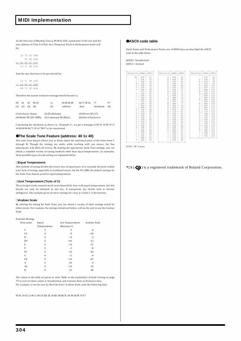
304
MIDI Implementation
As the data size of Rhythm Tone is 00 00 01 start address of Tone 4 of Part 16 at Temporbe;
14 70 00 00H
01 3E 00H
+) 00 00 01 41H
14 71 3F 41H
And the size that have to be got should be;
14 71 3F 41H
-) 10 00 00 00H
04 71 3F 41H
Therefore the system exclusive message sho
F0 41 10 00 10 11 1(1) (2) (3) (4) (5) a
(1) Exclusive Status, (2) ID (Roland),(4) Model ID (XV-5080), (5) Command ID
Calculating the checksum as shown in <Exa10 00 00 00 04 71 3F 41 7B F7 to be transmitt
●
The Scale Tune Feature (a
The scale Tune feature allows you to finelythrough B. Though the settings are maadjustments will affect all octaves. By makiobtain a complete variety of tuning methodthree possible types of scale setting are expl
❍
Equal Temperament
This method of tuning divides the octave inused form of tuning, especially in occidentathe Scale Tune feature produce equal tempe
❍
Just Temperament (Tonic of C)
The principal triads resound much more bebenefit can only be obtained in one keambiguous. The example given involves set
❍
Arabian Scale
By altering the setting for Scale Tune, you ethnic music. For example, the settings introScale.
Example SettingsNote name Equal Ju
Temperament (KC 0C# 0D 0D# 0E 0F 0F# 0G 0G# 0A 0A# 0B 0
The values in the table are given in cents. R??? to convert these values to hexadecimal, aFor example, to set the tune (C-B) of the Par
F0 41 10 42 12 40 11 40 3A 6D 3E 34 0D 38 6B
41H, summation of the size and theay Patch in Performance mode will
uld be sent is;
0 00 00 00 04 71 3F 41 ?? F7ddress data checksum (6)
(3) Device ID (17), (RQ1), (6) End of Exclusive
mple 2>, we get a message of F0 41 10 00 10 11ed.
ddress: 40 1x 40) adjust the individual pitch of the notes from Cde while working with one octave, the fineng the appropriate Scale Tune settings, you cans other than equal temperament. As examples,
ained below.
to 12 equal parts. It is currently the most widelyl music. On the XV-5080, the default settings forrament.
autifully than with equal temperament, but thisy. If transposed, the chords tend to becometings for a key in which C is the keynote.
can obtain a variety of other tunings suited forduced below will set the unit to use the Arabian
st Temperament Arabian Scaleeytone C)
0 -6-8 +45
+4 -2+16 -12-14 -51
-2 -8-10 +43+2 -4
+14 +47-16 0
+14 -10-12 -49
efer to the explanation of Scale Tuning on pagend transmit them as Exclusive data.
t1 Arabian Scale, send the following data:
3C 6F 40 36 0F 76 F7
● ASCII code table
Patch Name and Performance Name, etc, of MIDI data are described the ASCIIcode in the table below.
(HEX) = hexadecimal(DEC) = decimal
+—————————+—————+—————+ +—————————+—————+—————+ +—————————+—————+—————+ |Character|(HEX)|(DEC)| |Character|(HEX)|(DEC)| |Character|(HEX)|(DEC)| +—————————+—————+—————+ +—————————+—————+—————+ +—————————+—————+—————+ | SP | 20H | 32 | | @ | 40H | 64 | | ` | 20H | 96 | | ! | 21H | 33 | | A | 41H | 65 | | a | 61H | 97 | | " | 22H | 34 | | B | 42H | 66 | | b | 62H | 98 | | # | 23H | 35 | | C | 43H | 67 | | c | 63H | 99 | | $ | 24H | 36 | | D | 44H | 68 | | d | 64H | 100 | | % | 25H | 37 | | E | 45H | 69 | | e | 65H | 101 | | & | 26H | 38 | | F | 46H | 70 | | f | 66H | 102 | | ' | 27H | 39 | | G | 47H | 71 | | g | 67H | 103 | | ( | 28H | 40 | | H | 48H | 72 | | h | 68H | 104 | | ) | 29H | 41 | | I | 49H | 73 | | i | 69H | 105 | | * | 2AH | 42 | | J | 4AH | 74 | | j | 6AH | 106 | | + | 2BH | 43 | | K | 4BH | 75 | | k | 6BH | 107 || , | 2CH | 44 | | L | 4CH | 76 | | l | 6CH | 108 | | - | 2DH | 45 | | M | 4DH | 77 | | m | 6DH | 109 | | . | 2EH | 46 | | N | 4EH | 78 | | n | 6EH | 110 | | / | 2FH | 47 | | O | 4FH | 79 | | o | 6FH | 111 | | 0 | 30H | 48 | | P | 50H | 80 | | p | 70H | 112 | | 1 | 31H | 49 | | Q | 51H | 81 | | q | 71H | 113 | | 2 | 32H | 50 | | R | 52H | 82 | | r | 72H | 114 | | 3 | 33H | 51 | | S | 53H | 83 | | s | 73H | 115 | | 4 | 34H | 52 | | T | 54H | 84 | | t | 74H | 116 | | 5 | 35H | 53 | | U | 55H | 85 | | u | 75H | 117 | | 6 | 36H | 54 | | V | 56H | 86 | | v | 76H | 118 | | 7 | 37H | 55 | | W | 57H | 87 | | w | 77H | 119 | | 8 | 38H | 56 | | X | 58H | 88 | | x | 78H | 120 | | 9 | 39H | 57 | | Y | 59H | 89 | | y | 79H | 121 | | : | 3AH | 58 | | Z | 5AH | 90 | | z | 7AH | 122 | | ; | 3BH | 59 | | [ | 5BH | 91 | | { | 7BH | 123 | | < | 3CH | 60 | | \ | 5CH | 92 | | | | 7CH | 124 | | = | 3DH | 61 | | ] | 5CH | 93 | | } | 7CH | 125 | | > | 3EH | 62 | | ^ | 5CH | 94 | +—————————+—————+—————+| ? | 3FH | 63 | | _ | 5CH | 95 | +—————————+—————+—————+ +—————————+—————+—————+
NOTE : "SP" is space.
*GS ( ) is a registered trademark of Roland Corporation.
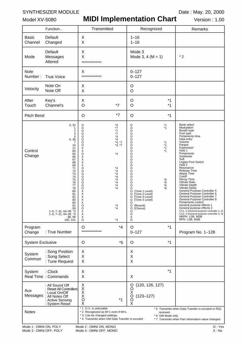
Function...
BasicChannel
Mode
NoteNumber :
Velocity
AfterTouch
Pitch Bend
ControlChange
ProgramChange
System Exclusive
SystemCommon
SystemReal Time
AuxMessages
Notes
Transmitted Recognized Remarks
DefaultChanged
DefaultMessagesAltered
True Voice
Note OnNote Off
Key'sChannel's
0, 321245
6, 387
1011646566676869717273747576777880818283849193
1–5, 7–31, 64–95 *31–5, 7–31, 64–95 *3
98, 99100, 101
: True Number
: Song Position: Song Select: Tune Request
: Clock: Commands
: All Sound Off: Reset All Controllers: Local On/Off: All Notes Off: Active Sensing: System Reset
XX
XX
XX
X
XO
O
OOOOOOOOXXOXXXXOOOOOOOOXXXXXOOXXXO
OOOOOOOOOOOOOOOOO O OOOOOO (Tone 1 Level)O (Tone 2 Level)O (Tone 3 Level)O (Tone 4 Level)OO (Reverb)O (Chorus)OOX O
O *4**************
O
XXX
XX
XXXXO *1X
1–161–16
Mode 3Mode 3, 4 (M = 1)
OO
0–127 0–127
O *1O *1
O *1
O *10–127
O *1
XXX
X
O (120, 126, 127)O XO (123–127)OX
Bank selectModulationBreath typeFoot typePortamento timeData entryVolumePanpotExpression Hold 1PortamentoSostenutoSoftLegato Foot SwitchHold 2ResonanceRelease TimeAttack TimeCutoffDecay TimeVibrato RateVibrato DepthVibrato DelayGeneral Purpose Controller 5General Purpose Controller 6General Purpose Controller 7General Purpose Controller 8Portamento controlGeneral purpose effects 1General purpose effects 3CC1, 2 (General purpose controller 1, 2)CC3, 4 (General purpose controller 3, 4)NRPN LSB, MSBRPN LSB, MSB
* 1 O X is selectable.* 2 Recognized as M=1 even if M≠1.* 3 Can be changed settings.* 4 Transmits when GM Data Transfer is excuted .
SYNTHESIZER MODULE
Model XV-5080
Date : May. 20, 2000
Version : 1.00MIDI Implementation Chart
**************
**************
Mode 1 : OMNI ON, POLYMode 3 : OMNI OFF, POLY
Mode 2 : OMNI ON, MONOMode 4 : OMNI OFF, MONO
O : YesX : No
* 2
Program No. 1–128
*4*7*7*7*4*4*4, *7*4, *7
*4
*4*4*4*4*4*4*4*4
*4*4
*4
*1*1
*1*1*1*1
*6*6*6*6
*7
*7
*5
*1
* 5 Transmits when Data Transfer is excuted or RQ1 received.* 6 GM Mode only.* 7 Transmits when Part Information value changed.
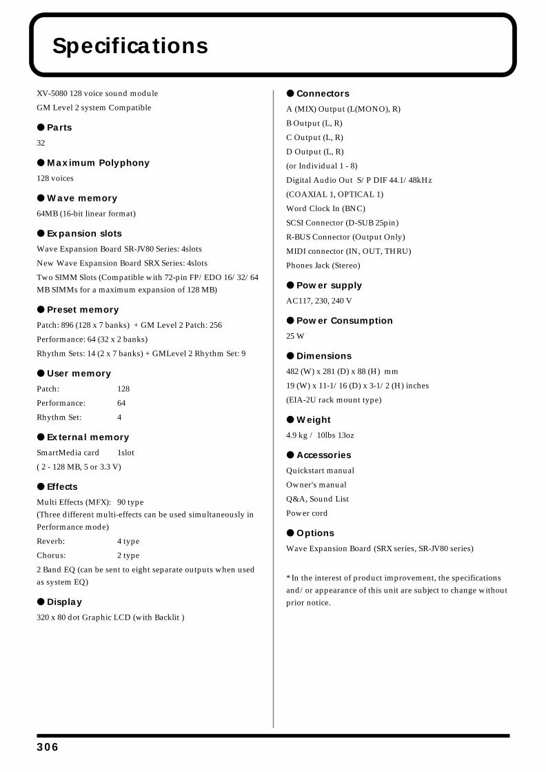
3
Specifications
XV-5080 128 voice sound module
GM Level 2 system Compatible
● Parts
32
● Maximum Polyphony
128 voices
● Wave memory
64MB (16-bit linear format)
● Expansion slots
Wave Expansion Board SR-JV80 Series: 4slots
New Wave Expansion Board SRX Series: 4slots
Two SIMM Slots (Compatible with 72-pin FP/EDO 16/32/64 MB SIMMs for a maximum expansion of 128 MB)
● Preset memory
Patch: 896 (128 x 7 banks) + GM Level 2 Patch: 256
Performance: 64 (32 x 2 banks)
Rhythm Sets: 14 (2 x 7 banks) + GMLevel 2 Rhythm Set: 9
● User memory
Patch: 128
Performance: 64
Rhythm Set: 4
● External memory
SmartMedia card 1slot
( 2 - 128 MB, 5 or 3.3 V)
● Effects
Multi Effects (MFX): 90 type(Three different multi-effects can be used simultaneously in Performance mode)
Reverb: 4 type
Chorus: 2 type
2 Band EQ (can be sent to eight separate outputs when used as system EQ)
● Display
320 x 80 dot Graphic LCD (with Backlit )
● Connectors
A (MIX) Output (L(MONO), R)
B Output (L, R)
C Output (L, R)
D Output (L, R)
(or Individual 1 - 8)
Digital Audio Out S/P DIF 44.1/48kHz
(COAXIAL 1, OPTICAL 1)
Word Clock In (BNC)
SCSI Connector (D-SUB 25pin)
R-BUS Connector (Output Only)
MIDI connector (IN, OUT, THRU)
Phones Jack (Stereo)
● Power supply
AC117, 230, 240 V
● Power Consumption
25 W
● Dimensions
482 (W) x 281 (D) x 88 (H) mm
19 (W) x 11-1/16 (D) x 3-1/2 (H) inches
(EIA-2U rack mount type)
● Weight
4.9 kg / 10lbs 13oz
● Accessories
Quickstart manual
Owner's manual
Q&A, Sound List
Power cord
● Options
Wave Expansion Board (SRX series, SR-JV80 series)
* In the interest of product improvement, the specifications and/or appearance of this unit are subject to change without prior notice.
06
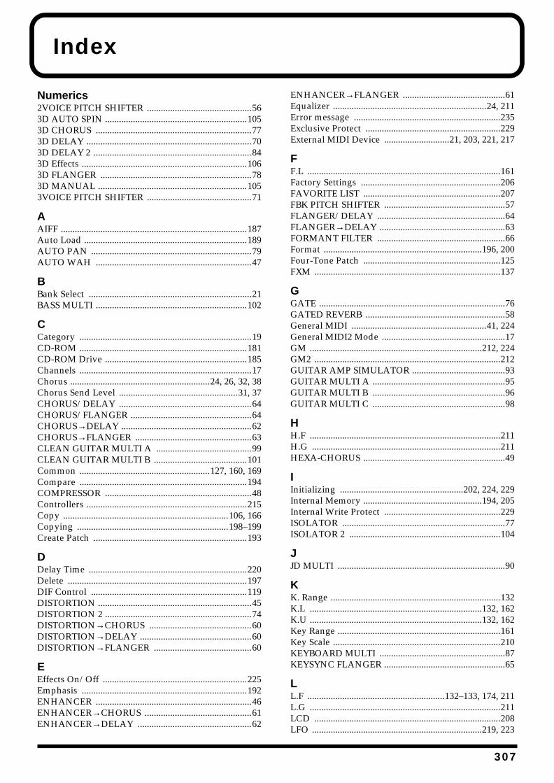
Index
Numerics2VOICE PITCH SHIFTER .............................................563D AUTO SPIN .............................................................1053D CHORUS ...................................................................773D DELAY .......................................................................703D DELAY 2 ....................................................................843D Effects .......................................................................1063D FLANGER .................................................................783D MANUAL ................................................................1053VOICE PITCH SHIFTER .............................................71
AAIFF ................................................................................187Auto Load ......................................................................189AUTO PAN .....................................................................79AUTO WAH ...................................................................47
BBank Select ......................................................................21BASS MULTI .................................................................102
CCategory ..........................................................................19CD-ROM ........................................................................181CD-ROM Drive .............................................................185Channels ..........................................................................17Chorus ............................................................24, 26, 32, 38Chorus Send Level ...................................................31, 37CHORUS/DELAY .........................................................64CHORUS/FLANGER ....................................................64CHORUS→DELAY ........................................................62CHORUS→FLANGER ..................................................63CLEAN GUITAR MULTI A .........................................99CLEAN GUITAR MULTI B ........................................101Common ........................................................127, 160, 169Compare ........................................................................194COMPRESSOR ...............................................................48Controllers .....................................................................215Copy .......................................................................106, 166Copying .................................................................198–199Create Patch ..................................................................193
DDelay Time ....................................................................220Delete .............................................................................197DIF Control ...................................................................119DISTORTION ..................................................................45DISTORTION 2 ...............................................................74DISTORTION→CHORUS ............................................60DISTORTION→DELAY ................................................60DISTORTION→FLANGER ..........................................60
EEffects On/Off ..............................................................225Emphasis .......................................................................192ENHANCER ...................................................................46ENHANCER→CHORUS ..............................................61ENHANCER→DELAY .................................................62
ENHANCER→FLANGER ............................................61Equalizer ..................................................................24, 211Error message ...............................................................235Exclusive Protect ..........................................................229External MIDI Device ............................21, 203, 221, 217
FF.L ...................................................................................161Factory Settings ............................................................206FAVORITE LIST ...........................................................207FBK PITCH SHIFTER ....................................................57FLANGER/DELAY .......................................................64FLANGER→DELAY ......................................................63FORMANT FILTER .......................................................66Format ....................................................................196, 200Four-Tone Patch ...........................................................125FXM ................................................................................137
GGATE ................................................................................76GATED REVERB ............................................................58General MIDI ..........................................................41, 224General MIDI2 Mode .....................................................17GM ..........................................................................212, 224GM2 ................................................................................212GUITAR AMP SIMULATOR ........................................93GUITAR MULTI A .........................................................95GUITAR MULTI B .........................................................96GUITAR MULTI C .........................................................98
HH.F ..................................................................................211H.G .................................................................................211HEXA-CHORUS .............................................................49
IInitializing .....................................................202, 224, 229Internal Memory ...................................................194, 205Internal Write Protect ..................................................229ISOLATOR ......................................................................77ISOLATOR 2 .................................................................104
JJD MULTI ........................................................................90
KK. Range .........................................................................132K.L ..........................................................................132, 162K.U ..........................................................................132, 162Key Range ......................................................................161Key Scale ........................................................................210KEYBOARD MULTI ......................................................87KEYSYNC FLANGER ....................................................65
LL.F ...........................................................132–133, 174, 211L.G ..................................................................................211LCD ................................................................................208LFO .........................................................................219, 223
307
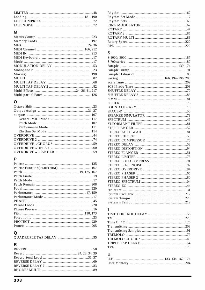
LIMITER ..........................................................................48Loading ..................................................................181, 190LOFI COMPRESS ...........................................................72LOFI NOISE ....................................................................72
MMatrix Control ..............................................................223Memory Cards ..............................................................197MFX ............................................................................24, 36MIDI Channel .......................................................166, 212MIDI IN .........................................................................213MIDI Keyboard ...............................................................17Mode ................................................................................17MODULATION DELAY ...............................................53Monophonic ....................................................................23Moving ...........................................................................198MULTI .............................................................................82MULTI TAP DELAY ......................................................68MULTI TAP DELAY 2 ...................................................82Multi-Effects ................................................24, 26, 41, 217Multi-partial Patch .......................................................126
OOctave Shift .....................................................................23Output Assign ..........................................................31, 37outputs ...........................................................................107
General MIDI Mode ...............................................117Patch Mode ..............................................................107Performance Mode .................................................111Rhythm Set Mode ...................................................114
OVERDRIVE ...................................................................44OVERDRIVE 2 ................................................................74OVERDRIVE→CHORUS ..............................................59OVERDRIVE→DELAY .................................................60OVERDRIVE→FLANGER ............................................59
PPalette .............................................................................135Palette Function(PERFORM) ......................................167Patch .................................................................19, 125, 167Patch Finder ....................................................................19Patch Mode .....................................................................17Patch Remain ................................................................208Pedal ...............................................................................220Performance ............................................................17, 159Performance Mode .........................................................17PHASER ...........................................................................45Phrase Loops .................................................................220Phrase Preview ...............................................................16Pitch ........................................................................138, 173Polyphonic ......................................................................23PROTECT ......................................................................229Protect ............................................................................205
QQUADRUPLE TAP DELAY .........................................55
RREVERB ...........................................................................58Reverb ............................................................24, 28, 34, 39Reverb Send Level ....................................................31, 37REVERSE DELAY ..........................................................69REVERSE DELAY 2 .......................................................83RHODES MULTI ............................................................89
Rhythm ..........................................................................167Rhythm Set Mode ...........................................................17Rhythm Sets ..................................................................168RING MODULATOR ....................................................67ROTARY ..........................................................................47ROTARY 2 .......................................................................85ROTARY MULTI ............................................................86Rotary Speed .................................................................220RPN ................................................................................222
SS-1000/3000 ...................................................................187S-700 series ....................................................................187Sample ....................................................................139, 174Sample Dump ...............................................................191Sampler Libraries .........................................................185Saving .....................................................166, 194–196, 200Scale Tune ......................................................................209SCSI Probe Time ...........................................................208SHUFFLE DELAY ..........................................................70SHUFFLE DELAY 2 .......................................................83SIMM ..............................................................................181SLICER .............................................................................76SOUND LIBRARY ..........................................................18SPACE-D .........................................................................50SPEAKER SIMULATOR ................................................73SPECTRUM .....................................................................46ST FORMANT FILTER ..................................................81STEP FLANGER .............................................................52STEREO AUTO WAH ...................................................81STEREO CHORUS .........................................................50STEREO COMPRESSOR ...............................................75STEREO DELAY .............................................................52STEREO DISTORTION .................................................94STEREO FLANGER .......................................................51STEREO LIMITER ..........................................................75STEREO LOFI COMPRESS ...........................................91STEREO LO-FI NOISE ...................................................92STEREO OVERDRIVE ...................................................94STEREO PHASER ..........................................................65STEREO PHASER 2 .......................................................80STEREO SPECTRUM ...................................................104STEREO-EQ .....................................................................44Structure ........................................................................131System Exclusive ..........................................................212System Tempo ...............................................................220System’s Tempo ............................................................219
TTIME CONTROL DELAY .............................................56TMT ................................................................................223Tone On/Off .................................................................126Transmitting ..................................................................203Transmitting Samples ..................................................191TREMOLO .......................................................................79TREMOLO CHORUS .....................................................49TRIPLE TAP DELAY .....................................................54TVF .................................................................................175
UU.F ..........................................................133–134, 162, 174User Memory ................................................................204
308
VV. Range .........................................................................133V.L ..........................................................................133, 174V.U ..........................................................................133, 174
WWAV ...............................................................................187WAVE ............................................................................136Wave ..............................................................................170Write ...............................................................................194
ZZip Disk .........................................................................190
309
InformationWhen you need repair service, call your nearest Roland Service Center or authorized Roland distributor in your country as shown below.
As of August 1, 2002 (Roland)
ARGENTINAInstrumentos Musicales S.A.Av.Santa Fe 2055 (1123) Buenos AiresARGENTINATEL: (011) 4508-2700 BRAZILRoland Brasil LtdaRua San Jose, 780 Sala BParque Industrial San JoseCotia - Sao Paulo - SP, BRAZILTEL: (011) 4615 5666
MEXICOCasa Veerkamp, s.a. de c.v.Av. Toluca No. 323, Col. Olivar de los Padres 01780 Mexico D.F. MEXICOTEL: (55) 5668-6699
PANAMASUPRO MUNDIAL, S.A.Boulevard Andrews, Albrook, Panama City, REP. DE PANAMATEL: 315-0101
U. S. A. Roland Corporation U.S.5100 S. Eastern AvenueLos Angeles, CA 90040-2938,U. S. A.TEL: (323) 890 3700
VENEZUELAMusicland Digital C.A.Av. Francisco de Miranda,Centro Parque de Cristal, Nivel C2 Local 20 CaracasVENEZUELATEL: (212) 285-8586
AUSTRALIA Roland Corporation Australia Pty., Ltd. 38 Campbell Avenue Dee Why West. NSW 2099 AUSTRALIA TEL: (02) 9982 8266 NEW ZEALAND Roland Corporation Ltd.32 Shaddock Street, Mount Eden, Auckland, NEW ZEALAND TEL: (09) 3098 715
HONG KONGTom Lee Music Co., Ltd. Service Division22-32 Pun Shan Street, Tsuen Wan, New Territories, HONG KONGTEL: 2415 0911 INDIARivera Digitec (India) Pvt. Ltd.409, Nirman Kendra Mahalaxmi Flats Compound Off. Dr. Edwin Moses Road, Mumbai-400011, INDIATEL: (022) 493 9051 INDONESIAPT Citra IntiRamaJ1. Cideng Timur No. 15J-150 Jakarta PusatINDONESIATEL: (021) 6324170
MALAYSIABENTLEY MUSIC SDN BHD140 & 142, Jalan Bukit Bintang 55100 Kuala Lumpur,MALAYSIATEL: (03) 2144-3333
PHILIPPINESG.A. Yupangco & Co. Inc.339 Gil J. Puyat AvenueMakati, Metro Manila 1200,PHILIPPINESTEL: (02) 899 9801
SINGAPORESwee Lee Company150 Sims Drive,SINGAPORE 387381TEL: 6846-3676
TAIWANROLAND TAIWAN ENTERPRISE CO., LTD.Room 5, 9fl. No. 112 Chung Shan N.Road Sec.2, Taipei, TAIWAN, R.O.C.TEL: (02) 2561 3339 THAILANDTheera Music Co. , Ltd.330 Verng NakornKasem, Soi 2, Bangkok 10100, THAILANDTEL: (02) 2248821
BAHRAINMoon StoresNo.16, Bab Al Bahrain Avenue, P.O.Box 247, Manama 304, State of BAHRAINTEL: 211 005
VIETNAMSaigon Music138 Tran Quang Khai St., District 1Ho Chi Minh CityVIETNAMTEL: (08) 844-4068
JORDANAMMAN Trading Agency 245 Prince Mohammad St., Amman 1118, JORDANTEL: (06) 464-1200
KUWAITEasa Husain Al Yousifi Est.Abdullah Salem Street,Safat, KUWAITTEL: 243-6399 LEBANONChahine S.A.L.Gerge Zeidan St., Chahine Bldg., Achrafieh, P.O.Box: 16-5857Beirut, LEBANONTEL: (01) 20-1441
QATARAl Emadi Co. (Badie Studio & Stores)P.O. Box 62, Doha, QATARTEL: 4423-554 SAUDI ARABIAaDawliah Universal Electronics APLCorniche Road, Aldossary Bldg., 1st Floor, Alkhobar,SAUDI ARABIA
P.O.Box 2154, Alkhobar 31952SAUDI ARABIA TEL: (03) 898 2081
TURKEY Barkat muzik aletleri ithalat ve ihracat Ltd StiSiraselviler Caddesi Siraselviler Pasaji No:74/20 Taksim - Istanbul, TURKEYTEL: (0212) 2499324 U.A.E.Zak Electronics & Musical Instruments Co. L.L.C.Zabeel Road, Al Sherooq Bldg., No. 14, Grand Floor, Dubai, U.A.E.TEL: (04) 3360715
EGYPTAl Fanny Trading Office9, EBN Hagar A1 Askalany Street,ARD E1 Golf, Heliopolis, Cairo 11341, EGYPTTEL: 20-2-417-1828 REUNIONMaison FO - YAM Marcel25 Rue Jules Hermann,Chaudron - BP79 97 491Ste Clotilde Cedex,REUNION ISLANDTEL: (0262) 218-429
SOUTH AFRICAThat Other Music Shop (PTY) Ltd.11 Melle St., Braamfontein, Johannesbourg, SOUTH AFRICA
P.O.Box 32918, Braamfontein 2017 Johannesbourg, SOUTH AFRICATEL: (011) 403 4105
Paul Bothner (PTY) Ltd.17 Werdmuller Centre, Main Road, Claremont 7708SOUTH AFRICA
P.O.BOX 23032, Claremont 7735, SOUTH AFRICATEL: (021) 674 4030
CYPRUSRadex Sound Equipment Ltd.17, Diagorou Street, Nicosia, CYPRUSTEL: (022) 66-9426
DENMARK Roland Scandinavia A/SNordhavnsvej 7, Postbox 880,DK-2100 CopenhagenDENMARK TEL: (039)16 6200 FRANCERoland France SA4, Rue Paul Henri SPAAK, Parc de l'Esplanade, F 77 462 St. Thibault, Lagny Cedex FRANCETEL: 01 600 73 500 FINLANDRoland Scandinavia As, Filial FinlandLauttasaarentie 54 BFin-00201 Helsinki, FINLANDTEL: (9) 682 4020 GERMANY Roland Elektronische Musikinstrumente HmbH.Oststrasse 96, 22844 Norderstedt, GERMANY TEL: (040) 52 60090
GREECESTOLLAS S.A.Music Sound Light155, New National RoadPatras 26442, GREECETEL: (061) 043-5400 HUNGARYRoland East Europe Ltd.Warehouse Area ‘DEPO’ Pf.83H-2046 Torokbalint, HUNGARYTEL: (23) 511011 IRELANDRoland IrelandAudio House, Belmont Court,Donnybrook, Dublin 4.Republic of IRELANDTEL: (01) 2603501
ITALYRoland Italy S. p. A. Viale delle Industrie 8, 20020 Arese, Milano, ITALYTEL: (02) 937-78300 NORWAYRoland Scandinavia Avd. Kontor NorgeLilleakerveien 2 Postboks 95 Lilleaker N-0216 Oslo NORWAYTEL: 273 0074 POLANDP. P. H. BrzostowiczUL. Gibraltarska 4.PL-03664 Warszawa POLANDTEL: (022) 679 44 19 PORTUGALTecnologias Musica e Audio, Roland Portugal, S.A.Cais Das Pedras, 8/9-1 Dto4050-465 PORTOPORTUGALTEL: (022) 608 00 60
RUSSIAMuTek3-Bogatyrskaya Str. 1.k.l107 564 Moscow, RUSSIA TEL: (095) 169 5043
SPAINRoland Electronics de España, S. A. Calle Bolivia 239, 08020 Barcelona, SPAINTEL: (93) 308 1000
SWITZERLANDRoland (Switzerland) AG Landstrasse 5, Postfach,CH-4452 Itingen, SWITZERLANDTEL: (061) 927-8383
SWEDEN Roland Scandinavia A/S SWEDISH SALES OFFICEDanvik Center 28, 2 tr. S-131 30 Nacka SWEDEN TEL: (08) 702 0020
UKRAINETIC-TACMira Str. 19/108P.O. Box 180 295400 Munkachevo, UKRAINETEL: (03131) 414-40 UNITED KINGDOM Roland (U.K.) Ltd.Atlantic Close, Swansea Enterprise Park, SWANSEASA7 9FJ, UNITED KINGDOMTEL: (01792) 700139
KOREACosmos Corporation1461-9, Seocho-Dong,Seocho Ku, Seoul, KOREATEL: (02) 3486-8855
AUSTRIARoland Austria GES.M.B.H.Siemensstrasse 4, P.O. Box 74,A-6063 RUM, AUSTRIATEL: (0512) 26 44 260 BELGIUM/HOLLAND/LUXEMBOURGRoland Benelux N. V.Houtstraat 3, B-2260, Oevel (Westerlo) BELGIUMTEL: (014) 575811
AFRICA
CHILEComercial Fancy S.A.Rut.: 96.919.420-1Nataniel Cox #739, 4th FloorSantiago - Centro, CHILETEL: (02) 688-9540
URUGUAYTodo Musica S.A.Francisco Acuna de Figueroa 1771C.P.: 11.800 Montevideo, URUGUAYTEL: (02) 924-2335
EUROPE
AUSTRALIA/NEW ZEALAND
ASIA
CENTRAL/LATINAMERICA
NORTH AMERICA
MIDDLE EAST
AFRICA
EL SALVADOROMNI MUSIC75 Avenida Norte y Final Alameda Juan Pablo , Edificio No.4010 San Salvador, EL SALVADORTEL: 262-0788
ROMANIAFBS LINESPiata Libertatii 1,RO-4200 GheorghehiTEL: (095) 169-5043
PARAGUAYDistribuidora De Instrumentos MusicalesJ.E. Olear y ESQ. Manduvira Asuncion PARAGUAYTEL: (021) 492-124
COSTA RICAJUAN Bansbach Instrumentos MusicalesAve.1. Calle 11, Apartado 10237,San Jose, COSTA RICATEL: 258-0211
CRISTOFORI MUSIC PTE LTDBlk 3014, Bedok Industrial Park E, #02-2148, SINGAPORE 489980TEL: 6243-9555
IRANMOCO, INC.No.41 Nike St., Dr.Shariyati Ave.,Roberoye Cerahe MirdamadTehran, IRANTEL: (021) 285-4169
ISRAELHalilit P. Greenspoon & Sons Ltd.8 Retzif Ha'aliya Hashnya St.Tel-Aviv-Yafo ISRAELTEL: (03) 6823666
SYRIATechnical Light & Sound CenterKhaled Ebn Al Walid St.Bldg. No. 47, P.O.BOX 13520, Damascus, SYRIATEL: (011) 223-5384
CANADA Roland Canada Music Ltd.(Head Office)5480 Parkwood Way Richmond B. C., V6V 2M4 CANADA TEL: (604) 270 6626
Roland Canada Music Ltd.(Toronto Office)170 Admiral BoulevardMississauga On L5T 2N6 CANADA TEL: (905) 362 9707
CHINARoland Shanghai Electronics Co.,Ltd.5F. No.1500 Pingliang Road Shanghai, CHINATEL: (021) 5580-0800
Roland Shanghai Electronics Co.,Ltd.(BEIJING OFFICE)10F. No.18 AnhuaxiliChaoyang District, Beijing, CHINATEL: (010) 6426-5050


02019812 ’02-10-F2-71N


![Whirlpool Delta Awm 5080 [ET]](https://static.fdocuments.net/doc/165x107/5480135cb4795979578b45f0/whirlpool-delta-awm-5080-et.jpg)