XO-4 Hardware Specification
18
XO-4 Hardware Design Specification Feb. 14, 2013
-
Upload
nguyendung -
Category
Documents
-
view
228 -
download
0
Transcript of XO-4 Hardware Specification
XO-4 Hardware Design Specification
Feb. 14, 2013
XO-4 Hardware Design Specification
Rev. 1.03, 2/14/13 Page 2 of 18
XO-4 Hardware Design Specification
Contents
Table of Contents1 Introduction ........................................................................................................................................................5
1.1 GENERAL SPECIFICATIONS .......................................................................................................................................5
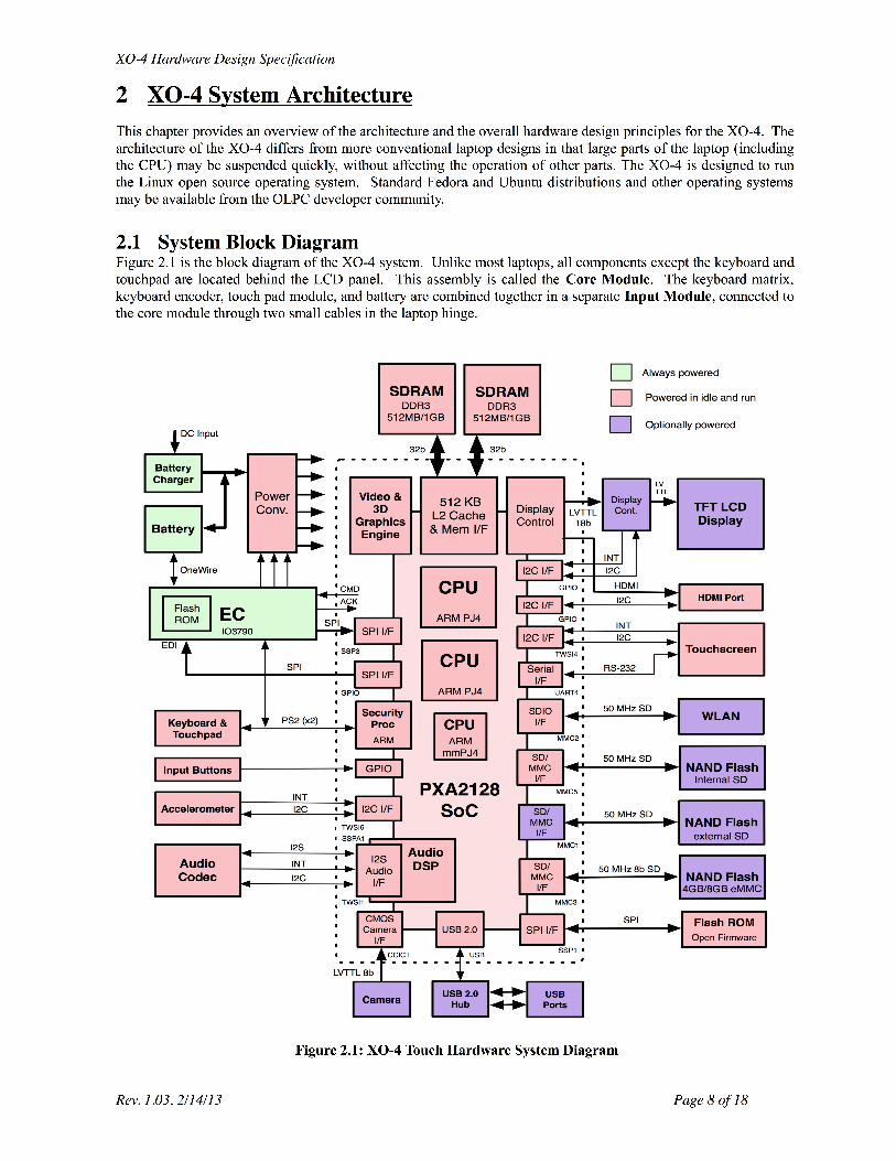
2 XO-4 System Architecture..................................................................................................................................82.1 SYSTEM BLOCK DIAGRAM .......................................................................................................................................82.2 CPU & COMPANION CHIP ......................................................................................................................................92.3 POWER CONVERSION................................................................................................................................................92.4 EMBEDDED CONTROLLER .......................................................................................................................................102.5 DISPLAY ..............................................................................................................................................................122.6 DISPLAY CONTROLLER...........................................................................................................................................122.7 AUDIO ................................................................................................................................................................132.8 STORAGE SYSTEM..................................................................................................................................................132.9 WIRELESS NETWORKING INTERFACE ........................................................................................................................142.10 CAMERA MODULE .............................................................................................................................................142.11 USER INPUT DEVICES ..........................................................................................................................................152.12 I/O PORTS ........................................................................................................................................................16
3 Testing ..............................................................................................................................................................173.1 SAFETY................................................................................................................................................................173.2 ENVIRONMENTAL CONDITIONS.................................................................................................................................173.3 DURABILITY ........................................................................................................................................................173.4 CONCERN FOR THE ENVIRONMENT ...........................................................................................................................17
Rev. 1.03, 2/14/13 Page 3 of 18

XO-4 Hardware Design Specification
History v1.0 - Created from the XO-1.75 specification. Changes include system architecture improvements, betterexplanation of the different models is now provided, descriptions of the touchscreen and mechanical keyboardwere added, and minor corrections were made.v1.02 - Changes to the wireless networking section, minor formatting fixesv1.03 - Corrected audio input.
Rev. 1.03, 2/14/13 Page 4 of 18

XO-4 Hardware Design Specification
1 Introduction This document introduces the system architecture and hardware design requirements for the XO-4 Touch Laptop(CL4/CL4A) and the XO-4 Laptop (CL4B/CL4C). While the functionality of the XO-4 is similar to an ordinarynotebook PC, it was designed by One Laptop per Child as a laptop for elementary school children. The foremostgoal of the hardware design is low-power operation. To achieve this goal, the XO-4 utilizes a very low powerARM processor and incorporates novel technologies such as a low power dual mode TFT LCD display and a lowpower networking interface.
The XO-4 is designed for outdoor use with a 19 cm (diagonal) 4:3 aspect ratio color/monochrome dual mode TFTLCD panel and a dust and moisture resistant keyboard and case. For ruggedness and low power, it uses NANDFlash as storage device in the system. To allow many hours of operation it supports a 20 WH battery.
The XO-4 is a system/motherboard upgrade to the original XO-1 design. No changes to the overall industrialdesign or tooling will be made. The addition of four raised dots (in a diamond pattern) to the hinge cover allowseasy differentiation of XO-1, XO-1.5, XO-1.75 and XO-4 machines in the field.
Four basic models of the XO-4 laptop are available: XO-4 Touch - this laptop integrates a multi-touch touchscreen on the LCD display, and has a water-
resistant keyboard suitable for use by small children. XO-4 HS Touch - this laptop integrates a multi-touch touchscreen on the LCD display, and has a
traditional (non-membrane) keyboard. XO-4 - this laptop has a water-resistant keyboard suitable for small children, but no touchscreen. XO-4 HS - this laptop has a traditional (non-membrane) keyboard, but no touchscreen.
The features of the laptop are described in section 2. Testing and certification is described in section 3.
1.1 General Specifications Processor & core system: Marvell PXA2128 System on Chip, including:
Dual core ARM PJ4 processors, running at 1 GHz or 1.2 GHz 32KiB/32KiB L1 caches, 512 KiB unified L2 cache1024 MiByte or 2048 MiByte DDR3L SDRAM system memoryEmbedded controller for system monitoring, battery charging, and solar power inputISA Compatibility: ARM v6 and v7, with Thumb and WMMX2* instruction set extensions Storage: 4 Gibytes or 8 GiBytes of eMMC NAND Flash memory on motherboard – other storage size options also available1 MByte of serial Flash memory provided separately for Open Firmware32 KByte of serial Flash memory provided separately for EC FirmwareExpandable through an externally accessible SD/MMC memory card socket, or an optional internalmicroSD/MMC memory card socket. Audio: Internal stereo speakers and amplifier Internal monoaural microphone Jack for external stereo headphone Jack for external mono microphone, sensor, or switch
Display: 7.5in (19 cm) color/monochrome dual mode TFT LCD, 1200x900 (200dpi) Viewing area: 152.4 mm x 114.3 mm; 6 in x 4.5 inSunlight readable Solid state (LED) backlight Touch Screen (only on XO-4 Touch and XO-4 HS Touch models):7.5in (19 cm) Infrared touchscreen, using zForce technology, developed in collaboration with Neonode.* WMMX2 is a a trademark of Intel.Rev. 1.03, 2/14/13 Page 5 of 18

XO-4 Hardware Design SpecificationSupports multiple touch points.Can be used with finger, stylus or pencils, without exerting pressure.Does not interfere with the sunlight readable display.Resilient and easily repairable.
Camera module: Integrated user-facing color video camera 640 x 480 resolution Full frame rate (30fps) Wireless Networking: Integrated IEEE 802.11/b/g (2.4 GHz) wireless networking interface.Optional: IEEE 802.11a/b/g/n (2.4 GHz and 5GHz) integrated wireless networking interface.Ad-hoc and AP mode networking supported Capable of network operation when CPU is suspended.
Expansion Ports: Two external USB 2.0 ports provided
Video Out Port:MicroHDMI port mirrors the integrated display for an external monitor or projector.
Input Devices: XO-4 and XO-4 Touch: Water and dust proof 80+ key rubber keyboard, with 1.6 mm stroke.XO-4 HS and XO-4 HS Touch: 77 key mechanical keyboard, with 1.8 mm stroke.Capacitive touchpad used for pointing deviceThree-axis Accelerometer provides information about laptop movement.
Buttons: Power button on the side of the display Screen rotate button on the side of the display Two sets of 4-direction cursor control buttons Magnetic sensor detects laptop closure Magnetic sensor detects use in eBook mode Indicators: Power on/off LED Battery status LED (Dual color) Wi-Fi status LEDStorage status LEDHardware controlled internal Microphone In Use LED Hardware controlled Camera In Use LED Power Conversion: DC power input, from 11V to 25V Integrated charger for Ni-MH/ LiFePO4 batteries High efficiency LED Backlight control circuit 6 mm power input connector (1.65 mm center pin) Overall Safety: IEC 60950-1 qualifiedEN 60950-1 qualifiedCSA/UL 60950-1 qualifiedASTM F 963 – Standard Consumer Spec on Toy Safety qualified Battery Pack: 2 cells of LiFePO4 AF type or five cells of NiMH with integrated gas gauge IC2800 mAh typical capacityLiFePO4: 5.5V to 7.5V operating range (@0.2C discharge)LiFePO4: 0 ~ +50°C operating temp. range
Rev. 1.03, 2/14/13 Page 6 of 18
XO-4 Hardware Design SpecificationNiMH: 5.5V to 8.5V operating range (@0.2C discharge)NiMH: 0 ~ +35°C operating temp. rangeSafety: UL 1642 and UL 2054 qualifiedA minimum of 50% charge left after 2000 charge cycles
AC adapter: 25W external AC adapter 90v(-10%) ~ 240v(+25%), 35-60Hz, AC input 13.5V DC output Safety: IEC 60950-1, EN 60950-1 & CSA/UL 60950-1 qualified Extra Transient and Burst Immunity: IEC 61000-4-4 passed Extra Surge Immunity: IEC 61000-4-5 passed Weight: <1.6Kg Size: 245mm (9.65") × 230mm (9") × 30.5mm (1.2")
Rev. 1.03, 2/14/13 Page 7 of 18
XO-4 Hardware Design Specification
2.2 CPU & Companion Chip The core processing system used in XO-4 is the Marvell PXA2128, which integrates multiple ARM processorcores and multi-level coherent caches. The PXA2128 also includes a graphics processing unit, two integratedmemory controllers providing an interleaved unified memory, a “security processor” and integrated displaycontrollers. Also included are I2S interfaces to the sound sytem, a USB 2.0 controller, power management logic,and system components such as real time clock (RTC), memory transfer engines (DMA), and programmableinterrupt controllers.
2.2.1 Interrupts Dedicated system interrupts are provided for system timer, keyboard, Audio codec, SDIO (used for SD cards andnetworking), Camera, Accelerometer, system control, USB, display control, touchpad, and DMA.
2.2.2 Firmware In XO-4, Open Firmware resides in a dedicated SPI Flash ROM. The Embedded Controller firmware is storedseparately, in a Flash ROM internal to the EC. Both Firmware ROMs have hardware protection to preventoverwriting by malicious application or system software. The Open Firmware Flash ROM is also used to store manufacturing information about the laptop (up to 64KiBytes).
2.2.3 Graphics Processing Unit A 3D graphics-processing unit (GPU) is provided in XO-4 to accelerate common graphics and video operations.This GPU shares the main memory with the main processors, using a unified memory architecture. It providesseparate processing pipelines for video and graphics, with a hardware blend before display. Separate color-spaceconversion and rescaling is provided for each pipeline. 2.2.4 Security Processor The SoC integrates a small ARM processor, identified as the “security processor”, which controls early boot stagesand handles keyboard and mouse input streams. It interacts with the embedded controller to manage power statesof the system, allowing fast wakeup on keyboard input.
2.2.5 Memory The XO-4 processor supports two integral 32 bit wide DDR3L SDRAM interfaces. No external buffering is used.Four 16-bit wide DDR3L SDRAM ICs are directly mounted on the motherboard, supporting 1 GByte of mainmemory. Alternatively, parts can be installed for 2 GByte main memory configuration. The speed of this memorybus is currently 400 MHz.
As the memory is mounted on the motherboard, and not expandable, there is no SPD interface supported fordetecting the speed or size of memory.
2.3 Power ConversionThe power subsystem design in the XO-4 is complex relative to a normal laptop. In order to minimize the powerconsumption, the power supplied to a number of subsystems may be sequenced on or off as needed.
2.3.1 Battery Charger The XO-4 provides a DC power input jack. A DC voltage source between 11 and 25 volts is suitable for poweringthe laptop. The DC input jack will safely withstand an input voltage between –32V and 40V. Exceeding theseinput parameters should not cause permanent harm to the laptop, but will destroy an internal fuse, requiring repair.
An integrated battery charger is provided, which converts power input to the laptop into voltages suitable forcharging and controls the charge current.
The battery charger supports both constant voltage and constant current charging algorithms, under control offirmware running on the Embedded Controller.
The battery charger is designed to limit in hardware the power drained from an external input. The total inputwattage is limited to 25W. If the laptop components are drawing less than this amount, any remaining power isused to charge the battery. The charging voltages supported are 7.5V for LiFePO4, and 8.5V for NiMH.
2.3.2 Battery Pack
Rev. 1.03, 2/14/13 Page 9 of 18
XO-4 Hardware Design SpecificationXO-4 is designed to support a variety of battery technologies. Currently, the laptops are available with batterypacks comprised of two LiFePO4 cells in series, or five NiMH cells in series. Each battery pack contains anintegral gas gauge IC.
The battery packs can be recharged 2000 times (to 50% capacity – as repeated charge and discharge slowlydecreases how much power can be stored in the battery). Nonetheless, these batteries last approximately fourtimes longer than the standard laptop batteries that are typically specified as rechargeable 500 times (to 50%capacity).
Communications between the laptop and the gas gauge chip are carried over a single wire, using the DallasSemiconductor One-Wire protocol and specifications. This single wire interface allows the laptop’s EmbeddedController to read information about a battery pack’s technology, status, and history. It even allows the laptop topower the gas gauge chip in batteries that have been discharged completely. A three-pin connector is used betweenthe battery pack and XO-4.
2.3.3 Backlight control The XO-4 LCD backlight is provided by white LEDs. Multiple LEDs are connected in series into three chains inorder to equalize their brightness. These chains are powered in parallel. LEDs from all three chains should beinterleaved, to minimize the impact of a single chain burning out. Up to 60 mA of current (at 17.6V) is provided todrive the backlight.
Two signals are used to control the backlight operation. One enables/disables the backlight, and a second one ispulse-width modulated at 200Hz to generate a voltage that varies the brightness of the backlight.
2.3.4 Power Timing Sequence Whenever a battery is inserted into a XO-4, or power is supplied to the DC power input, the system EmbeddedController (EC) is powered and operating.
2.3.4.1 Power Off to On If the laptop power button is pressed, the EC supplies power to the power management logic in the companionchip, and communicates the power button press to it. The companion chip will enable power to the main memory,processor, and most other components of the system. The EC notices this action, and powers up the displaycontroller in response. The display controller then powers up the LCD display and backlight.
2.3.4.2 On to Suspend If the operating system determines that the CPU should be suspended in order to conserve power, it takes theneeded steps to disable the operation of any co-processors which might access main memory, notifies thenetworking interface, places the main memory in a low power self-refresh mode, then notifies the powermanagement logic in the companion chip. This logic will disable power from the processor and most othercomponents of the system. Parts of the companion chip, the main memory, the display and display controller, thebacklight, the keyboard, and the networking interface remain powered and operational.
2.3.4.3 Suspend to On When any button press is detected, either from the keyboard or the buttons around the display (power, rotate, andgame keys/pad), the EC notifies both the display controller and the power management logic in the SoC. Thedisplay controller immediately unblanks the display (if blanked due to inactivity). The power management logicenables power to the processor and most other components.
2.3.4.4 On to Off When the operating system determines that the laptop should be turned off (usually in response to the power buttonbeing pressed), it sends a command to the EC. The EC disables power to all subsystems, including the keyboard,display controller and networking interface. If powered by the DC Power input, the EC remains awake to handlebattery charging. If operating from a battery, the EC enters a deep sleep state and awaits a press of the powerbutton (or the arrival of DC Power input).
2.4 Embedded Controller The Embedded Controller (EC) is a microprocessor providing a number of critical system monitoring andmanagement functions. These include system power management and battery management. It is poweredwhenever there is a battery with sufficient charge or the laptop has DC power input, although it enters a sleep modewhen possible. Rev. 1.03, 2/14/13 Page 10 of 18
XO-4 Hardware Design Specification
The EC communicates with the main processor through an SPI interface. A second SPI interface is used to upgradethe firmware internal to the EC from the main processor.
2.4.1 Programming Interface The functions supported by the EC are best described by the programming interface provided for use by the XO-4firmware and operating system. This interface defines the laptop hardware that the EC must monitor and control.
Firmware and operating system running on the XO-4 laptop may read the following hardware status through theEmbedded Controller, using I/O ports (in the x86 input/output address space) 0x6C and 0x68:
• Battery Voltage • Battery Current • Battery Accumulated Current Register (ACR) • Battery Temperature • Ambient Temperature • Battery Status (Exists, Fully Charged, Low, Destroyed, DC Power input present)• Battery State of Charge • Battery Gas Gauge Serial Number • Laptop motherboard ID • System Control Interrupt (SCI) Source
o Game Button o Battery Status Change
DC Power input provided or removed Battery inserted or removed Battery low Battery full Battery destroyed
o Battery SOC change o Battery subsystem error o eBook mode change o Lid status change
• System Control Interrupt Mask • Display Panel Button Status (eight directional game keys and display rotate) • Battery subsystem error
o Pack info fail (LiFePO4 & NiMH) o Over voltage checking fail (LiFePO4) o Over temperature (58C) (LiFePO4) o Gauge stop or sensor break (LiFePO4& NiMH) o Sensor out of control (NiMH) o Battery ID fail & temperature > 52C o Accumulated Charge Register fail (NiMH)
• Laptop power status (Display Controller, Wireless mesh networking interface) Firmware and operating system running on the XO-4 laptop may control the following hardware functions throughthe Embedded Controller:
• Set System Control Interrupt (SCI) Mask • Initialize NiMH and LiFePO4Battery • Enable/Disable Wireless mesh networking interface (WLAN) power • Wake up WLAN • Reset WLAN • Enable/Disable Display Controller power
2.4.2 Embedded Controller Firmware The firmware for the Embedded Controller is stored in a separate 32 KiByte serial Flash memory internal to the ECIC.
2.4.2.1 Write Protect Function In order to prevent malicious software from rewriting crucial firmware and manufacturing information stored in the
Rev. 1.03, 2/14/13 Page 11 of 18
XO-4 Hardware Design SpecificationEmbedded Controller and Open Firmware Boot ROM, XO-4 provides a firmware write protect mechanism. Thismechanism is only disabled by a full system reset. It is enabled by the main processor. Once enabled, the writeprotect may not be disabled except by another system reset.
After a system reset, firmware from the serial Flash will be loaded and executed by the main processor. If thefirmware determines that a trusted update to the firmware is available, it may perform the update at that time(followed by a reboot of both the EC and the main processor). If no update is available, the main processor writeprotects the serial Flash, before execution of the operating system begins. This prevents malicious applications ormodifications of the OS from modifying the basic firmware and boot process.
2.5 Display The TFT LCD display used is a unique design, developed specifically for the XO-4, and produced by Chi MeiInnolux. It is a dual mode 19cm display, providing a color display when used in transparent mode, and a very lowpower monochrome display when used in reflective mode. It can be used in bright sunlight.
In reflective (monochrome) mode, it supports a display of 1200 x 900 pixels (200 dots per inch), each capable of64 gray levels. The frame buffer stores a full 24 bits for each pixel. In transmissive (color) mode, the perceivedresolution is 1024x768 or higher, depending on the ambient illumination.
As a transflective display, the luminance depends on the ambient lighting. In a dimly lit room (140 cd/m2), thedisplay luminance is 100 luxcd/m2, minimum, and typically 120 luxcd/m2. In office lighting (350 luxcd/m2), theluminance is typically 170 luxcd/m2, and in daylight, the luminance is roughly 25% of the ambient illumination.The contrast ratio of the display is 85:1 in low ambient illumination.
The LCD backlight for transmissive mode is provided by white LEDs. Multiple LEDs are connected in series intothree chains in order to equalize their brightness. These chains are then powered in parallel. LEDs from all threechains are interleaved, to minimize the impact of a single chain burning out. The exact spectrum (white point) ofthe LEDs used in the backlight is not specified, but the LEDs used in any single backlight are closely matched toprovide a uniform backlight spectrum.
The dimensions of the LCD are 17.0cm x 14.0cm x 0.62cm (thick). The active display area is 15.2cm by 11.4cm,and the bezel area is 15.5cm by 11.7cm. Its weight is only 172g.
As the XO-4 design minimizes the length of the cabling between the display controller and the display, a dual-edgeTTL signaling protocol is used for interfacing. One 55-pin flexible cable provides data connections, with aseparate 4-pin flex cable connecting the integral LED backlight to the laptop motherboard.
2.6 Display ControllerDisplay controllers in conventional integrated processors and laptops do not meet the low power designrequirements of the XO-4. Until suitable display controllers become available, a separate display control (DCON)application-specific integrated circuit developed for XO-4 will be used. The DCON provides the followingfeatures:
• Autonomous display refresh, independent of the CPU or GPU’s power state • Support for “color swizzling”, allowing a conventional graphics engine to drive the dual-modecolor/monochrome LCD display• Monochrome mode support provides for a pixel-addressable automatic color-to-gray-scale conversion mode • Optional anti-aliasing improves text display in color mode • A dual-edge TTL output for interfacing to the XO-4 LCD display.
The DCON is designed to work with a conventional display controller. It provides an input interface emulating aTTL-compatible LCD display, allowing direct connection to a conventional display controller. In normaloperation, when the conventional display controller is powered and operating, the DCON simply passes the videodirectly through, performing any required transformations (color swizzling with anti-aliasing or monochromemode) but not buffering any of the video. Before the operating system places the laptop into suspend power mode, it notifies the DCON and the DCONbuffers the frame of video being displayed in its own memory. The DCON will then continue to display this frameuntil notified by the operating system that it has exited suspend mode and is generating valid video again. Rev. 1.03, 2/14/13 Page 12 of 18
XO-4 Hardware Design Specification
2.7 Audio The XO-4 provides both internal and external audio input and output. Internally, stereo speakers are provided oneach side of the display, along with a single channel microphone mounted on one side of the display. Jacks areprovided for use of headphones, external speakers, or an external microphone.
The audio subsystem is built around an I2S Audio Codec, which provides conversion between digital and analogaudio signals, as well as mixing capabilities. This codec supports input or output sampling at rates up to 48 KHz,using analog/digital converters with a dynamic range of 80 dB and digital/analog converters with a dynamic rangeof over 90 dB. The audio codecs support operation with either 16 bit or 24 bit audio data.
2.7.1 Internal Speakers There are two internal speakers in the XO-4 laptop, each driven by a separate audio channel. These are driven by adedicated audio amplifier capable of providing 1.4 W continuously into each speaker, with a total harmonicdistortion of 1%. The frequency response of the internal speakers is roughly from 480 Hz to 40 KHz.
2.7.2 Internal Microphone An internal microphone is included with XO-4, located on the left side of the display. This provides a singlechannel of audio input. The microphone is an electret condenser microphone, with a minimum S/N of 56 dB, and aminimum sensitivity of –46 dB (0 dB at 1Pa, freq. of 1 KHz).
An indicator light is provided near the microphone on the left side of the display that indicates if the microphone iscurrently being used (turned on). This light is directly controlled by hardware whenever it is possible for theinternal microphone to be in use. It may not be disabled by software.
2.7.3 External Headphones or Speakers A stereo jack is provided on the laptop for connecting headphones or an external amplifier and speakers. When aplug is inserted into this jack, the internal speakers are automatically disconnected and their amplifier is powereddown. The state of this jack may be determined by software.
The headphone is driven by an amplifier integrated with the audio codec, capable of providing 30mW continuouslyinto a 32Ω impedance.
2.7.4 External Microphone Input A mono jack is provided on the laptop for connecting an external microphone, switch, or other sensor. This jack isconnected to the audio codec’s microphone input, with provides a programmable gain preamplifier. The inputimpedance is 10 KΩ.
A DC blocking capacitor may be inserted into the input signal path, under software control. This is used when theinput is an audio signal. When used, the frequency response of the input is flat down to 10 Hz.
A bias voltage (2.0 or 2.5V, with a 3 KΩ source impedance) may also be driven onto this external microphoneinput, under software control. This may be used to power external electret condenser microphones, or externalpassive sensors (such an external switch or thermistor). Due to the high impedance of the bias source, this inputmay safely be shorted to ground.
An external voltage applied to this input is limited to the range of -9V to +9V. Inputs exceeding this range maycause excessive current to flow through a protective diode.
When the external microphone jack is in use, the internal microphone is disconnected, and the indicator lightindicating microphone use is disabled. The state of this jack may be queried by software.
2.8 Storage SystemXO-4 has no spinning media storage devices, such as hard disk drives or optical drives. It relies on NAND Flashmemory for non-volatile storage. 4 or 8 GBytes of NAND Flash are provided using a single internal eMMC devicemounted on the motherboard. Alternative SKUs which provide other size internal Flash storage may be provided.The interface between the processor and the NAND is critical to system performance. It is high-speed (guaranteedto be at least 2MBytes/s with regular performance above 10 MBytes/s) and provides error-correction and wear-
Rev. 1.03, 2/14/13 Page 13 of 18

XO-4 Hardware Design Specificationleveling functions in hardware.
The endurance of the NAND device is five thousand erase cycles, with a data retention lifetime of at least tenyears. Wear-leveling of the device to avoid premature failure is provided in hardware.
The XO-4 also provides an internal microMMC/SD card slot for replacing a failed eMMC device. The actual cardsocket is not provided, but may easily be added in a repair facility.
The XO-4 also provides a single external full size MMC/SD card slot for extending the laptop’s storage.
2.9 Wireless Networking Interface The XO-4 laptops provide a wireless network interface for communication with other laptops and the Internet.Two wireless networking options are available: one providing 802.11b/g (2.4 GHz only), and the other providing802.11a/b/g/n (5 and 2.4 GHz). Both networking options provide a separate ARM processor, offloadingnetworking functions from the main processor.
The wireless interfaces are custom to the XO laptop, in order to minimize power consumption. They use a +1.8V4-bit SDIO running at 50 MHz, both to reduce signaling power and support fast suspend/resume. They obtainmultiple supply voltages from the more efficient power conversion system on the motherboard.
The 802.11b/g wireless interface also supports the draft 802.11s mesh networking protocol through the use of theOpen 802.11s software stack.
Figure 2.9: External Antenna
2.9.1 Antenna Design The antennas for wireless networking on XO-4 are designed to provide the best performance possible. Tworotatable external antennas are provided, located at the top right and left corners of the display, frequently referredto as rabbit ears. The ability to rotate the antennas up, away from the body of the laptop, provides optimumantenna performance. When the rabbit ears are down, they cover the laptop’s I/O ports (USB and audio), andprovide a latching mechanism.
2.10 Camera Module The XO-4 provides a video camera with a fixed lens, located on the right side of the display. This camera has aresolution of 640 x 480 pixels, and may operate at up to thirty frames per second. It provides a signal/noise ratio ofat least 46 dB, and has a sensor array size of 2.36mm x 1.76mm. The F-number of the optical system is 2.8 (+/-5%), effective focal length is 2.45mm, and the field of view is 60 degrees.
Parameters of the video camera (such as automatic gain control, automatic exposure control, automatic whitebalance, lens correction, manual color balance, or black level control) are adjustable under software control. An indicator light is provided near the camera on the right side of the laptop display which indicates whether theRev. 1.03, 2/14/13 Page 14 of 18
XO-4 Hardware Design Specificationcamera is currently being used (turned on). This light is directly controlled by hardware whenever it is possiblethat the camera might be in use. It may not be disabled by software.
2.11 User Input Devices In addition to the microphone, and camera described separately, the user input devices provided on XO-4 are akeyboard, a touchpad, a directional gamepad and display rotation button on the left side of the display, and fourgame keys and a power button on the right side.
2.11.1 Touch ScreenThe XO-4 Touch and XO-4 HS Touch models are equipped with a infrared multi-touch capable touchscreen on theLCD display. This allows a more natural and intuitive user interface than the touchpad. The XO-4 Touch useszForce technology from Neonode technology, as it doesn't interfere with the sunlight readable display integratedinto the XO laptops.
At least two simultaneous touch points are supported, with additional simultaneous touches supported in someinterface layouts. The touchscreen detects fingers or a soft-tipped stylus, as long as the stylus has a diameter of 8mm or larger (measured within a mm of the end.)
The touchscreen interface is integrated into a removable bezel around the LCD panel. While it is quite resilient, itmay easily be replaced in case of damage.
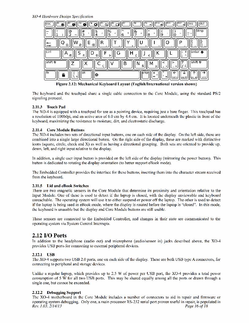
2.11.2 Keyboard
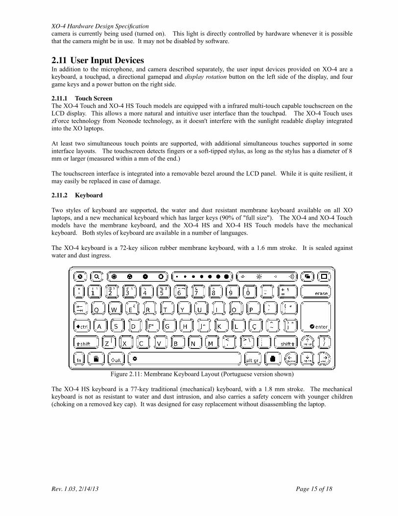
Two styles of keyboard are supported, the water and dust resistant membrane keyboard available on all XOlaptops, and a new mechanical keyboard which has larger keys (90% of "full size"). The XO-4 and XO-4 Touchmodels have the membrane keyboard, and the XO-4 HS and XO-4 HS Touch models have the mechanicalkeyboard. Both styles of keyboard are available in a number of languages.
The XO-4 keyboard is a 72-key silicon rubber membrane keyboard, with a 1.6 mm stroke. It is sealed againstwater and dust ingress.
Figure 2.11: Membrane Keyboard Layout (Portuguese version shown)
The XO-4 HS keyboard is a 77-key traditional (mechanical) keyboard, with a 1.8 mm stroke. The mechanicalkeyboard is not as resistant to water and dust intrusion, and also carries a safety concern with younger children(choking on a removed key cap). It was designed for easy replacement without disassembling the laptop.
Rev. 1.03, 2/14/13 Page 15 of 18
XO-4 Hardware Design Specificationproduction machines, but the remainder may be easily added to aid in software development. They are notaccessible unless the laptop is partially disassembled. These connectors include:
• Two RS-232 protocol serial connections (3.3V) to the main processor • A main processor JTAG connector • An RS-232 protocol serial connection (3.3V) to the Embedded Controller • An SPI interface for reprogramming the OFW boot ROM.• An SPI interface for reprogramming the EC firmware ROM.
3 Testing The XO-4 meets a wide range of environmental, mechanical, and electrical tests.
3.1 SafetyXO-4 meets UL and EC safety certification. The laptop meets IEC 60950-1, EN 60950-1, and CSA/UL 60950-1(Safety of Information Technology Equipment) specifications. It also complies with UL 1310 and UL 498. Inorder to guarantee the safety of children using the laptop, it also passes ASTM F 963 (Standard Consumer SafetySpecification on Toy Safety, 2003 edition).
The external power adapter complies with IEC, EN, and CSA/UL 60950-1. The removable battery pack complieswith IEC, EN, and CSA/UL 60950-1 and UL 2054 (Household and Commercial Batteries).
3.2 Environmental ConditionsXO-4 is designed for operation over an extended range of environmental conditions:
• Ambient Temperature: 0C to 50C • Operational Altitude: 0m to 5500 m • Non-operational Ambient Temperature: -20C to 60C
3.3 Durability The XO-4 was designed for durability and easy repair.
3.3.1 Input Devices The game buttons and gamepad are tested to 500,000 cycles.The membrane keyboard is tested to 5,000,000 cycles. The mechanical keyboard is tested to 1,000,000 cycles.All I/O connectors (Power, USB, Headphone, and Microphone) are tested to 5,000 insertion/removal cycles.
3.3.2 Drop Tests The XO-4 passes a 10 point free-drop test from a height of 80 cm onto a carpet, and a 10 point free-drop test froma height of 45 cm onto wood.
3.4 Concern for the Environment The XO is the most energy-efficient and environmentally friendly laptop ever made, based on independentevaluations and data. XO consumes the least power, minimizes toxic materials, is extraordinarily rugged, has along lifetime, works with renewable power sources, and is itself recyclable. XO has earned the highestenvironmental certifications: it is in full compliance with the European Union’s rigorous Reduction of HarmfulSubstances (RoHS) standards; it is designed for Energy Star Version 4.0 Category A Tier 2 performance, the moststringent level.. According to ENERGY STAR®, an average idle desktop computer uses 70 watts of power and an average idlinglaptop computer consumes 20 watts of power. When idle, the XO laptop uses as little as one watt of electricity.
Among the XO’s other environmentally friendly attributes and innovations:
Rev. 1.03, 2/14/13 Page 17 of 18
XO-4 Hardware Design SpecificationXO is more rugged — it will last longer, thus staying out of landfills longer. The XO has been designed for a five-year lifetime even in extreme environments like the outdoors, the jungle, and the desert. The average laptop has atwo-year lifetime when used in an office and far less when brought outside or to the desert. Doubling the lifetimeof the laptop halves its environmental impact. XO is about half the size and weight of typical laptops. Less material halves the environmental impact.
XO is designed for use with renewable energy sources. It's the first laptop designed to harvest energy directlyfrom solar cells and other power-limited energy sources. XO uses a new battery using LiFePO4 (Lithium Ferro Phosphate) chemistry that lasts four times longer thanstandard laptop batteries, and is vastly safer than the current dominant technology of Lithium Ion.
Rev. 1.03, 2/14/13 Page 18 of 18